JP4597990B2 - PFO closure device with flexible thrombogenic joint and improved detachability - Google Patents
PFO closure device with flexible thrombogenic joint and improved detachabilityDownload PDFInfo
- Publication number
- JP4597990B2 JP4597990B2JP2006526395AJP2006526395AJP4597990B2JP 4597990 B2JP4597990 B2JP 4597990B2JP 2006526395 AJP2006526395 AJP 2006526395AJP 2006526395 AJP2006526395 AJP 2006526395AJP 4597990 B2JP4597990 B2JP 4597990B2
- Authority
- JP
- Japan
- Prior art keywords
- anchor member
- central joint
- anchor
- materials
- tissue
- Prior art date
- Legal status (The legal status is an assumption and is not a legal conclusion. Google has not performed a legal analysis and makes no representation as to the accuracy of the status listed.)
- Expired - Fee Related
Links
- 230000002885thrombogenetic effectEffects0.000titleclaimsdescription9
- 239000000463materialSubstances0.000claimsdescription65
- 210000001519tissueAnatomy0.000claimsdescription41
- 239000002407tissue scaffoldSubstances0.000claimsdescription21
- 230000007547defectEffects0.000claimsdescription18
- 229920000642polymerPolymers0.000claimsdescription15
- 229910052751metalInorganic materials0.000claimsdescription14
- 239000002184metalSubstances0.000claimsdescription14
- HLXZNVUGXRDIFK-UHFFFAOYSA-Nnickel titaniumChemical compound[Ti].[Ti].[Ti].[Ti].[Ti].[Ti].[Ti].[Ti].[Ti].[Ti].[Ti].[Ni].[Ni].[Ni].[Ni].[Ni].[Ni].[Ni].[Ni].[Ni].[Ni].[Ni].[Ni].[Ni].[Ni]HLXZNVUGXRDIFK-UHFFFAOYSA-N0.000claimsdescription12
- 229910001000nickel titaniumInorganic materials0.000claimsdescription12
- 229940079593drugDrugs0.000claimsdescription11
- 239000003814drugSubstances0.000claimsdescription11
- 230000007246mechanismEffects0.000claimsdescription11
- 238000011084recoveryMethods0.000claimsdescription7
- 102000010834Extracellular Matrix ProteinsHuman genes0.000claimsdescription6
- 108010037362Extracellular Matrix ProteinsProteins0.000claimsdescription6
- 239000004372Polyvinyl alcoholSubstances0.000claimsdescription6
- 210000002744extracellular matrixAnatomy0.000claimsdescription6
- 229920002451polyvinyl alcoholPolymers0.000claimsdescription6
- 239000012781shape memory materialSubstances0.000claimsdescription6
- 229920000728polyesterPolymers0.000claimsdescription5
- 230000002757inflammatory effectEffects0.000claimsdescription4
- 102000008186CollagenHuman genes0.000claimsdescription3
- 108010035532CollagenProteins0.000claimsdescription3
- 239000004809TeflonSubstances0.000claimsdescription3
- 229920006362Teflon®Polymers0.000claimsdescription3
- 229920001436collagenPolymers0.000claimsdescription3
- 239000013536elastomeric materialSubstances0.000claimsdescription3
- 229920000295expanded polytetrafluoroethylenePolymers0.000claimsdescription3
- 239000004744fabricSubstances0.000claimsdescription3
- 239000007769metal materialSubstances0.000claimsdescription3
- 150000002739metalsChemical class0.000claimsdescription3
- 239000004814polyurethaneSubstances0.000claimsdescription3
- 229920002635polyurethanePolymers0.000claimsdescription3
- 238000002386leachingMethods0.000claims6
- 208000008883Patent Foramen OvaleDiseases0.000description56
- 238000000034methodMethods0.000description16
- 210000005245right atriumAnatomy0.000description16
- 238000001727in vivoMethods0.000description14
- 210000005246left atriumAnatomy0.000description13
- 238000010586diagramMethods0.000description9
- 210000003484anatomyAnatomy0.000description7
- 239000010408filmSubstances0.000description7
- 208000007536ThrombosisDiseases0.000description6
- 230000001746atrial effectEffects0.000description6
- 208000035478Interatrial communicationDiseases0.000description5
- 208000013914atrial heart septal defectDiseases0.000description5
- 206010003664atrial septal defectDiseases0.000description5
- 230000035876healingEffects0.000description5
- 208000005189EmbolismDiseases0.000description4
- 208000027418Wounds and injuryDiseases0.000description4
- 239000000853adhesiveSubstances0.000description4
- 230000001070adhesive effectEffects0.000description4
- 239000008280bloodSubstances0.000description4
- 210000004369bloodAnatomy0.000description4
- 230000002829reductive effectEffects0.000description4
- 239000003146anticoagulant agentSubstances0.000description3
- 238000013459approachMethods0.000description3
- 230000008901benefitEffects0.000description3
- 210000004491foramen ovaleAnatomy0.000description3
- 210000002837heart atriumAnatomy0.000description3
- 208000025339heart septal defectDiseases0.000description3
- RVTZCBVAJQQJTK-UHFFFAOYSA-Noxygen(2-);zirconium(4+)Chemical compound[O-2].[O-2].[Zr+4]RVTZCBVAJQQJTK-UHFFFAOYSA-N0.000description3
- 230000004044responseEffects0.000description3
- 238000001356surgical procedureMethods0.000description3
- 210000005166vasculatureAnatomy0.000description3
- 208000006011StrokeDiseases0.000description2
- 208000032109Transient ischaemic attackDiseases0.000description2
- 229940127219anticoagulant drugDrugs0.000description2
- 239000000560biocompatible materialSubstances0.000description2
- 230000015572biosynthetic processEffects0.000description2
- 208000026106cerebrovascular diseaseDiseases0.000description2
- 230000000694effectsEffects0.000description2
- 239000012530fluidSubstances0.000description2
- 239000011888foilSubstances0.000description2
- 239000003102growth factorSubstances0.000description2
- 238000002513implantationMethods0.000description2
- 230000028709inflammatory responseEffects0.000description2
- 238000004519manufacturing processMethods0.000description2
- 239000003550markerSubstances0.000description2
- BASFCYQUMIYNBI-UHFFFAOYSA-NplatinumChemical compound[Pt]BASFCYQUMIYNBI-UHFFFAOYSA-N0.000description2
- 230000001737promoting effectEffects0.000description2
- 230000001839systemic circulationEffects0.000description2
- 238000002560therapeutic procedureMethods0.000description2
- 201000010875transient cerebral ischemiaDiseases0.000description2
- 230000002792vascularEffects0.000description2
- 206010018852HaematomaDiseases0.000description1
- 208000032843HemorrhageDiseases0.000description1
- 208000032382Ischaemic strokeDiseases0.000description1
- 229920000291Poly(9,9-dioctylfluorene)Polymers0.000description1
- FAPWRFPIFSIZLT-UHFFFAOYSA-MSodium chlorideChemical compound[Na+].[Cl-]FAPWRFPIFSIZLT-UHFFFAOYSA-M0.000description1
- 230000005856abnormalityEffects0.000description1
- 230000006978adaptationEffects0.000description1
- 229910045601alloyInorganic materials0.000description1
- 239000000956alloySubstances0.000description1
- 238000005452bendingMethods0.000description1
- 208000034158bleedingDiseases0.000description1
- 230000000740bleeding effectEffects0.000description1
- 230000017531blood circulationEffects0.000description1
- 230000036772blood pressureEffects0.000description1
- 230000002490cerebral effectEffects0.000description1
- 230000008859changeEffects0.000description1
- 230000004087circulationEffects0.000description1
- 239000002131composite materialSubstances0.000description1
- 230000006835compressionEffects0.000description1
- 238000007906compressionMethods0.000description1
- 238000007796conventional methodMethods0.000description1
- 210000004351coronary vesselAnatomy0.000description1
- 230000007812deficiencyEffects0.000description1
- 230000002939deleterious effectEffects0.000description1
- 238000002716delivery methodMethods0.000description1
- 238000013461designMethods0.000description1
- 238000003745diagnosisMethods0.000description1
- 238000005538encapsulationMethods0.000description1
- 230000008020evaporationEffects0.000description1
- 238000001704evaporationMethods0.000description1
- 210000002458fetal heartAnatomy0.000description1
- 210000003754fetusAnatomy0.000description1
- 239000000945fillerSubstances0.000description1
- 238000002594fluoroscopyMethods0.000description1
- -1for exampleInorganic materials0.000description1
- 230000004927fusionEffects0.000description1
- PCHJSUWPFVWCPO-UHFFFAOYSA-NgoldChemical compound[Au]PCHJSUWPFVWCPO-UHFFFAOYSA-N0.000description1
- 229910052737goldInorganic materials0.000description1
- 239000010931goldSubstances0.000description1
- 210000005003heart tissueAnatomy0.000description1
- 230000000004hemodynamic effectEffects0.000description1
- 230000001939inductive effectEffects0.000description1
- 230000002401inhibitory effectEffects0.000description1
- 208000014674injuryDiseases0.000description1
- 230000003993interactionEffects0.000description1
- 238000005304joiningMethods0.000description1
- 238000003475laminationMethods0.000description1
- 230000000670limiting effectEffects0.000description1
- 210000004072lungAnatomy0.000description1
- 238000002595magnetic resonance imagingMethods0.000description1
- 239000000203mixtureSubstances0.000description1
- 238000012986modificationMethods0.000description1
- 230000004048modificationEffects0.000description1
- 229910000510noble metalInorganic materials0.000description1
- 229940127216oral anticoagulant drugDrugs0.000description1
- 230000036961partial effectEffects0.000description1
- 230000002093peripheral effectEffects0.000description1
- 229910052697platinumInorganic materials0.000description1
- 229920005594polymer fiberPolymers0.000description1
- 229920006254polymer filmPolymers0.000description1
- 239000002861polymer materialSubstances0.000description1
- 230000008569processEffects0.000description1
- 238000011321prophylaxisMethods0.000description1
- 230000004088pulmonary circulationEffects0.000description1
- 238000007788rougheningMethods0.000description1
- 238000007665saggingMethods0.000description1
- 229920000431shape-memory polymerPolymers0.000description1
- 239000011780sodium chlorideSubstances0.000description1
- 230000001225therapeutic effectEffects0.000description1
- 239000010409thin filmSubstances0.000description1
- 230000008733traumaEffects0.000description1
- 210000003954umbilical cordAnatomy0.000description1
- 210000004291uterusAnatomy0.000description1
- 238000012800visualizationMethods0.000description1
- 238000007794visualization techniqueMethods0.000description1
Images


Classifications
- A—HUMAN NECESSITIES
- A61—MEDICAL OR VETERINARY SCIENCE; HYGIENE
- A61B—DIAGNOSIS; SURGERY; IDENTIFICATION
- A61B17/00—Surgical instruments, devices or methods
- A61B17/0057—Implements for plugging an opening in the wall of a hollow or tubular organ, e.g. for sealing a vessel puncture or closing a cardiac septal defect
- A61B2017/00575—Implements for plugging an opening in the wall of a hollow or tubular organ, e.g. for sealing a vessel puncture or closing a cardiac septal defect for closure at remote site, e.g. closing atrial septum defects
- A61B2017/00592—Elastic or resilient implements
- A—HUMAN NECESSITIES
- A61—MEDICAL OR VETERINARY SCIENCE; HYGIENE
- A61B—DIAGNOSIS; SURGERY; IDENTIFICATION
- A61B17/00—Surgical instruments, devices or methods
- A61B17/0057—Implements for plugging an opening in the wall of a hollow or tubular organ, e.g. for sealing a vessel puncture or closing a cardiac septal defect
- A61B2017/00575—Implements for plugging an opening in the wall of a hollow or tubular organ, e.g. for sealing a vessel puncture or closing a cardiac septal defect for closure at remote site, e.g. closing atrial septum defects
- A61B2017/00606—Implements H-shaped in cross-section, i.e. with occluders on both sides of the opening
Landscapes
- Health & Medical Sciences (AREA)
- Surgery (AREA)
- Life Sciences & Earth Sciences (AREA)
- Medical Informatics (AREA)
- Animal Behavior & Ethology (AREA)
- Engineering & Computer Science (AREA)
- Biomedical Technology (AREA)
- Heart & Thoracic Surgery (AREA)
- Cardiology (AREA)
- Molecular Biology (AREA)
- Nuclear Medicine, Radiotherapy & Molecular Imaging (AREA)
- General Health & Medical Sciences (AREA)
- Public Health (AREA)
- Veterinary Medicine (AREA)
- Surgical Instruments (AREA)
- Materials For Medical Uses (AREA)
- Prostheses (AREA)
Description
Translated fromJapanese関連出願
本出願は、2001年12月19日に提出された米国仮出願第60/340,858号の利益を請求する、2002年12月19日に提出された米国特許出願第10/326,535号の一部継続出願である。RELATED APPLICATIONS This application claims the benefit of US Provisional Application No. 60 / 340,858, filed Dec. 19, 2001, and is filed with U.S. Patent Application No. 10/326, filed Dec. 19, 2002. This is a partial continuation application of 535.
発明の分野
本発明は、全般に、卵円孔開存などの身体の異常を閉鎖するための閉塞デバイスに関する。The present invention generally relates to an occlusive device for closing bodily abnormalities such as patent foramen ovale.
発明の背景
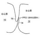
図1に示す卵円孔開存(PFO)は、心臓の右心房10と左心房12の間の壁に遺残する一方向の、通常はフラップ状の開口部である。左心房(LA)圧は、通常、右心房(RA)圧よりも高いため、フラップは、通常、閉鎖したままである。しかし、ある一定の条件では、右心房圧は左心房圧を超える可能性があり、血液が右心房10から左心房12に流れ、血餅が体循環に入り得る可能性が生じる。このような状況は起こらないことが望ましい。Background of the Invention The patent foramen ovale (PFO) shown in FIG. 1 is a unidirectional, usually flap-like opening that remains in the wall between the
卵円孔は、胎児が子宮内に在胎しているとき、望ましい目的を果たす。血液は、発達中の肺を通してではなく臍帯を通して酸素供給されるため、胎児の心臓の循環器系では、血液が右左シャントのための生理学的導管としての卵円孔を通って流れることが可能である。誕生後、肺循環が確立し、左心房の血流量および血圧の増大により卵円孔の機能的閉鎖が起こる。この機能的閉鎖に続いて、その後、2つの重なり合う組織層、即ち、一次中隔14と二次中隔16の解剖学的閉鎖が起こる。しかし、多数の成人でPFOが遺残していることが分かった。 The foramen ovale serves a desirable purpose when the fetus is conceived in the uterus. Because blood is oxygenated through the umbilical cord rather than through the developing lung, in the fetal heart circulatory system, blood can flow through the foramen ovale as a physiological conduit for the right and left shunts. is there. After birth, pulmonary circulation is established and functional closure of the foramen ovale occurs due to increased blood flow and blood pressure in the left atrium. This functional closure is followed by an anatomical closure of two overlapping tissue layers, the
PFOの存在は、一般に、その他の点で健康な成人では、治療の意義はないと考えられている。脳卒中又は一過性脳虚血発作(TIA)を患っている患者で、PFOがあり、且つ、他に明らかな虚血性脳卒中の原因がない場合、その診断でPFOによる奇異塞栓症が考えられる。現在のところ、因果関係の明確な証拠はないが、多くの研究で、PFOの存在と、奇異塞栓症又は脳卒中のリスクとの間に強い関連があることが確認されている。更に、脳血管障害の既往があるPFO患者は、将来、脳血管障害が再発するリスクが高いという有意な証拠がある。 The presence of PFO is generally considered to have no therapeutic significance in otherwise healthy adults. If the patient is suffering from a stroke or transient ischemic attack (TIA) and has PFO and no other obvious cause of ischemic stroke, the diagnosis may be an odd embolism due to PFO. At present, there is no clear evidence of causality, but many studies have confirmed that there is a strong association between the presence of PFO and the risk of bizarre embolism or stroke. Furthermore, there is significant evidence that PFO patients with a history of cerebrovascular disorders are at increased risk of recurrence of cerebrovascular disorders in the future.
従って、このようなリスクの高い患者には、塞栓症の再発リスクを減少させるため、予防的治療が考えられる。これらの患者は、通常、経口抗凝固剤で治療を行うが、これは、出血、血腫、および他の様々な薬物との相互作用などの有害な副作用を有する可能性がある。これらの薬物の使用は、人の回復を変化させ、人の日常生活パターンの調整を必要とする可能性がある。 Therefore, prophylactic treatment can be considered for such high-risk patients in order to reduce the risk of recurrence of embolism. These patients are usually treated with oral anticoagulants, which can have deleterious side effects such as bleeding, hematoma, and interactions with various other drugs. The use of these drugs can change a person's recovery and require adjustment of the person's daily life pattern.
抗凝固療法に禁忌を示すときなど、ある一定の場合には、PFOを閉鎖する手術が必要であるか又は望ましい場合がある。手術は、典型的には、二次中隔を一次中隔に付着させることにより、PFOを縫合して閉鎖することを含む。このような縫合付着は、断続的縫合又は連続縫合のどちらかを使用して達成することができ、外科医が直視下でPFOを閉鎖する通常の方法である。 In certain cases, such as when contraindicated for anticoagulant therapy, surgery to close the PFO may be necessary or desirable. Surgery typically involves suturing and closing the PFO by attaching a secondary septum to the primary septum. Such suture attachment can be accomplished using either intermittent sutures or continuous sutures, and is the usual method for a surgeon to close the PFO under direct vision.
当初、心房中隔欠損症(ASD)の経皮的閉鎖のために開発された、アンブレラデバイスおよび他の様々な類似の機械的閉鎖デバイスが、PFOの閉鎖に使用される場合があった。これらのデバイスによって、患者は、抗凝固療法に伴うことが多い副作用や侵襲性の手術のリスクを回避できる可能性がある。しかし、ASD用に設計されているアンブレラデバイスなどは、PFO閉鎖デバイスとして使用するのに最適ではない。 Initially, umbrella devices and various other similar mechanical closure devices developed for percutaneous closure of atrial septal defect (ASD) were sometimes used to close PFOs. These devices may allow patients to avoid the side effects often associated with anticoagulant therapy and the risk of invasive surgery. However, umbrella devices and the like designed for ASD are not optimal for use as PFO closure devices.
現在使用可能な中隔閉鎖デバイスには、埋め込み術が技術的に複雑であることを含む欠点がある。更に、血栓、構成要素の破損、伝導系の妨害、心臓組織の穿孔、および残留物の漏出による合併症は重大である。多くのデバイスは中隔プロファイルが大きく、多量の異物を含むため、デバイスが好ましくない身体適応を引き起こす場合がある。ASDデバイスが穴を閉塞するように設計されていることを考慮すると、多くのものは、PFOのフラップのような解剖学的構造に対する解剖学的適合性に欠けている。そのため、PFOを閉鎖するためASDデバイスを挿入するとき、狭い開口部と薄いフラップが障害となって適切に配備されない場合がある。閉塞状態に封鎖される場合でも、デバイスは、心臓に一定の角度で配備され、幾つかの構成要素が確実に中隔に当てて配置されないことがあり、それによって、血流力学的障害による血栓形成のリスクがある。最後に、中隔閉鎖デバイスには製造の複雑なものがあり、一貫した製品性能が得られない場合がある。 Currently available septal closure devices have drawbacks including the technical complexity of implantation. In addition, complications due to thrombus, component failure, conduction system obstruction, perforation of heart tissue, and leakage of residue are significant. Many devices have a large septal profile and contain a large amount of foreign matter, which can cause undesirable body adaptations. Considering that ASD devices are designed to occlude holes, many lack anatomical compatibility with anatomical structures such as PFO flaps. Therefore, when inserting an ASD device to close the PFO, the narrow opening and thin flaps may become an obstacle and not be properly deployed. Even when sealed in an occluded state, the device may be deployed at an angle to the heart, ensuring that some components are not placed against the septum, thereby causing a thrombus due to hemodynamic disturbances. There is a risk of formation. Finally, some septal closure devices are complex to manufacture and may not provide consistent product performance.
本発明は、従来技術の中隔閉鎖デバイスの前記および他の欠陥に対処するように設計されている。 The present invention is designed to address these and other deficiencies of prior art septal closure devices.
発明の実施形態の簡単な概要
本発明の様々な実施形態は、PFOなどの中隔欠損を閉鎖するためのデバイスに関する。閉鎖デバイスは、一般に、近位アンカー部材、遠位アンカー部材、および2つのアンカー部材を接続する可撓性中心継手を具備する。中心継手は、1つ以上の縫合糸であってもよい。或いは、中心継手は、組織の内方成長(ingrowth)を促進し得る又は薬物を送達し得る可撓性エラストマー層であってもよい。また、可撓性材料は、組織への接着を促進する生体適合性材料、又は組織の内方成長を加速する成長因子で被覆されてもよい。Brief Overview of Embodiments of the Invention Various embodiments of the present invention relate to devices for closing septal defects such as PFO. The closure device generally comprises a proximal anchor member, a distal anchor member, and a flexible central joint that connects the two anchor members. The central joint may be one or more sutures. Alternatively, the central joint can be a flexible elastomeric layer that can promote tissue ingrowth or deliver a drug. The flexible material may also be coated with a biocompatible material that promotes adhesion to tissue or a growth factor that accelerates tissue ingrowth.
本発明の幾つかの実施形態によれば、閉鎖デバイスは、永続的な異物が体内に実質的に残存しないように生体吸収性の構成要素で形成される。 According to some embodiments of the present invention, the closure device is formed of a bioabsorbable component so that permanent foreign matter does not substantially remain in the body.
本発明の他の実施形態によれば、閉鎖デバイスの近位および/又は遠位アンカー部材は、長さの中心部分に沿って分割され、部材の端部が押し合わせられると細長い楕円形を形成する略円筒状の部材を具備してもよい。勿論、円形の断面の他に様々な断面形状を使用してもよい。このような近位および/又は遠位アンカー部材は、二次元又は三次元であってもよい。このような近位および/又は遠位アンカー部材は、更に、組織スキャフォールドを具備してもよい。 According to other embodiments of the present invention, the proximal and / or distal anchor members of the closure device are split along a central portion of length and form an elongated oval when the ends of the members are pressed together A substantially cylindrical member may be provided. Of course, various cross-sectional shapes other than a circular cross-section may be used. Such proximal and / or distal anchor members may be two-dimensional or three-dimensional. Such proximal and / or distal anchor members may further comprise a tissue scaffold.
本発明の他の実施形態によれば、デバイスの送達、取り出し、および/又は再位置決めを容易にするため、閉鎖デバイスを折り畳む機構が提供される。 In accordance with other embodiments of the present invention, a mechanism for folding the closure device is provided to facilitate delivery, removal and / or repositioning of the device.
前記および他の特徴は、本発明の実施形態が例証として示され、説明される以下の詳細な説明から容易に明らかになる。理解されるように、本発明は、他の異なる実施形態が可能であり、その幾つかの詳細は様々な点で変更が可能であり、それらは全て本発明から逸脱するものではない。従って、図面および説明は、本質的に例証と見なされ、拘束的又は限定的な意味に解されるものではない。 These and other features will be readily apparent from the following detailed description, wherein embodiments of the invention are shown and described by way of illustration. As will be realized, the invention is capable of other and different embodiments, and its several details are capable of modifications in various respects, all of which do not depart from the invention. Accordingly, the drawings and descriptions are to be regarded as illustrative in nature, and are not to be construed in a restrictive or limiting sense.
実施形態の詳細な説明
本発明の様々な実施形態は、主に、欠損における治癒反応を誘発することによってPFOなどの中隔欠損を閉鎖する方法およびデバイスに関する。デバイスは、一般に、中隔欠損の各側のアンカー部材と、そのアンカー部材間にアンカー部材を接合する少なくとも1つの接続部材を具備する、様々な形状を有してもよい。少なくとも1つの接続部材は、欠損における治癒反応を促進する幾つかの形状の1つを有してもよい。DETAILED DESCRIPTION OF EMBODIMENTS Various embodiments of the present invention relate primarily to methods and devices for closing septal defects such as PFO by inducing a healing response in the defect. The device may generally have a variety of shapes with an anchor member on each side of the septal defect and at least one connecting member joining the anchor member between the anchor members. The at least one connecting member may have one of several shapes that promote a healing response in the defect.
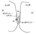
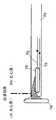
図2に示すように、本発明の1つ以上の実施形態によるPFO閉鎖デバイス18は、(PFOの左心房側に配置することができる)遠位アンカー構成要素又は部材20、(デバイスを所定の位置に固定するための)近位アンカー部材22、(取り付けおよびカテーテルからの放出のための)近位取り付け点24、および(例えば、この実施形態による普通の縫合糸とすることができる)中心接続部材26を具備する。 As shown in FIG. 2, a
幾つかの実施形態では、遠位アンカー、近位アンカー、および接続部材は、生体吸収性である。これらの構成要素は、単一の生体吸収性ポリマーから、又は2種類以上の材料の積層複合材料で製造され、例えば、剛性のある中心部と可撓性のある縁部を有するアンカー部材、および、速く完全な内皮化を促進するが血栓症は最小限にする制御された空隙率又は表面テクスチャを有する血液接触面などの特性の独自の混合を提供することができる。更に、アンカーの組織接触面は、例えば、粗くすることによって、更なる安定性を提供するように設計できる。 In some embodiments, the distal anchor, proximal anchor, and connecting member are bioabsorbable. These components are manufactured from a single bioabsorbable polymer or from a laminated composite of two or more materials, for example, an anchor member having a rigid center and flexible edges, and It can provide a unique mix of properties, such as a blood interface with a controlled porosity or surface texture, that promotes rapid and complete endothelialization but minimizes thrombosis. Furthermore, the tissue contacting surface of the anchor can be designed to provide additional stability, for example by roughening.
遠位アンカー20は、丸みを帯びた弓形の端部を有する、細長く、好ましくは略円筒状の細い棒のような部材である。組織表面との接触を増大させるため、アンカーの組織接触面を略平坦にすることができる。遠位アンカー構成要素は、サイズが、例えば、長さ15〜30mm、直径2mmで、円形の断面を有してもよい。近位アンカー22は、類似の寸法および形状を有してもよいが、近位アンカー22の方が全体的な長さが短くてもよい。 The
また、他の遠位および近位アンカー構造も可能である。例えば、図20および21の実施形態に関して後述されるような円筒状の形状を形成するように巻かれる、略平坦な材料でアンカーを形成することができる。 Other distal and proximal anchor structures are also possible. For example, the anchor can be formed of a substantially flat material that is wound to form a cylindrical shape as described below with respect to the embodiment of FIGS.
送達および配備するため、遠位アンカー20および近位アンカー22は、図3に示すように、送達シース又はカテーテル28内に縦方向に端と端が接して略整列するように位置決めされる。これらの構成要素は、可撓性接続部材26と共に、この縦方向の向きでカテーテル又は送達シース内を移動する。カテーテル又は送達シースを一次中隔と二次中隔の間に挿入し、左心房18に入れ、遠位アンカー構成要素20を放出する。次いで、カテーテル又は送達シース28を右心房の中に引っ込めて、近位アンカー22を放出する。可撓性中心接続部材26は、一次中隔と二次中隔の間に延在し、遠位アンカー20と近位アンカー22を接合する。遠位アンカーと近位アンカーは、放出されると、中心接続部材の軸に本質的に垂直に、且つ、互いに略平行な面にあるように概ね自動的に向きが定まる。その正確な向きは、個々の患者の解剖学的構造に支配される。「引っ込める」および「放出する」の用語は、相対的なものであり、送達カテーテルに関するデバイスの相対的な移動を総称的に表すことを意図している。 For delivery and deployment,
本デバイスの代替の送達方法は、PFOを通すのとは対照的に、直接一次中隔を通すデバイスの配備とすることができる。 An alternative delivery method for the device can be the deployment of the device directly through the primary septum, as opposed to through PFO.
遠位アンカーと近位アンカーを引き寄せることができるように、中心接続部材26をアンカーおよび止め機構22に取り付ける方法は、例えば、摩擦嵌合又は中心接続部材上での引結びとすることができる。引結びを使用する場合、その結び目に近い縫合糸の自由端を遠隔で保持し、結び目が適切な位置に配置された後、解放することができる。 The method of attaching the
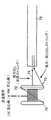
図4に示す本発明の1つ以上の代替の実施形態では、中心接続部材26は、近位アンカー22が中心接続部材26に対して自由に摺動できるように取り付けられる。伸張可能なコイルばねであってもよい付勢ばね30は、中心接続部材26の外端部に形成され、カテーテル又はシースから近位アンカーと遠位アンカーが両方とも配備されているとき、近位アンカーを遠位アンカーの方に付勢することができる。 In one or more alternative embodiments of the present invention shown in FIG. 4, the
図4および図5に示す実施形態では、適切な止めを提供し、近位アンカー22に圧縮力を加えるため、金属構成要素を中心接続部材26として使用してもよい。金属構成要素は、一端が遠位アンカー構成要素20に成形又は積層されている1片の形状記憶ワイヤとすることができる。図4では、近位アンカー22は中心接続部材26上で摺動し、それが配備されると、形状記憶ワイヤの端部に形成されている付勢ばね30が伸張し、近位アンカー22を遠位アンカー20の方に付勢する。 In the embodiment shown in FIGS. 4 and 5, a metal component may be used as the central connecting
図5の実施形態では、形状記憶ワイヤは、近位アンカーの中心を通って出て、伸張時に反対方向に湾曲して近位アンカーを遠位アンカーの方に引張る2本のワイヤから製造されるフックタイプのアンカー32を形成する。 In the embodiment of FIG. 5, the shape memory wire is manufactured from two wires that exit through the center of the proximal anchor and bend in the opposite direction when stretched to pull the proximal anchor toward the distal anchor. A
図4および図5の実施形態は、生体吸収性構成要素が溶解すると、永久的な異物が残る可能性があるが(例えば、中心接続部材26として金属構成要素を使用する場合)、これらのデバイスの利点の1つは、血栓形成性の組織スキャフォールド(通常は血管材料)が左心房側に配置されないことである。PFO閉鎖デバイスのLA側に形成する血栓は、放出されて体循環に入り、冠状動脈、脳循環(cerebral circulation)、又は、遠位の血管系で塞栓症を引き起こす可能性があり、PFOの閉鎖に使用されるほとんどの血管移植材料は、血栓形成性が高い。 Although the embodiments of FIGS. 4 and 5 may leave permanent foreign material when the bioabsorbable component dissolves (eg, when using a metal component as the central connecting member 26), these devices One advantage is that no thrombogenic tissue scaffold (usually vascular material) is placed on the left atrial side. The thrombus that forms on the LA side of the PFO closure device can be released into the systemic circulation and cause embolism in the coronary artery, cerebral circulation, or distal vasculature, and PFO closure Most vascular graft materials used in are highly thrombogenic.
PFO閉鎖デバイスは、X線で可視化でき、且つ、白金又は金などの貴金属から製造されてもよい放射線不透過性フィラー又はマーカーバンドと一緒に使用できなければならない場合がある。これらのマーカーは、例えば、接着、2つのポリマー層間の積層、又は蒸着などの様々な通常の方法を使用して取り付けることができる。 The PFO closure device may need to be usable with radiopaque fillers or marker bands that can be visualized with X-rays and may be made from noble metals such as platinum or gold. These markers can be attached using a variety of conventional methods such as adhesion, lamination between two polymer layers, or evaporation.
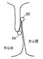
図6Aおよび図6Bは、本発明の他の1つ以上の実施形態による閉鎖デバイス50を示す。デバイス50は、可撓性(好ましくは、延伸性エラストマー性)中心継手又は接続要素56で接続されている近位および遠位アンカー部材52、54を具備する。アンカー部材52、54は、好ましくは円筒状の形状であり、端部が丸みを帯びている。遠位アンカー部材54のサイズは、例えば、長さ約15〜30mm、直径約2mmであり、円形の断面を有してもよい。近位アンカー52は類似の寸法および形状を有してもよいが、近位アンカー52の方が全体的な長さが短くてもよい。アンカー部材52、54は、好ましくは、比較的硬い(好ましくは生体吸収性の)ポリマー(通常または形状記憶)、又は、生体組織から製造される。生体適合性金属を使用することもできる。 6A and 6B illustrate a
また、他の遠位および近位アンカー構造も可能である。例えば、図20および21の実施形態に関して後述されるように、円筒状の形状を形成するように巻かれる略平坦な材料でアンカーを形成することができる。 Other distal and proximal anchor structures are also possible. For example, as described below with respect to the embodiment of FIGS. 20 and 21, the anchor can be formed of a substantially flat material that is wound to form a cylindrical shape.
図6のデバイスの中心継手56(並びに、図7〜図10、図12〜図18、および図21〜図24に示すデバイスの中心継手)は、好ましくは、エラストマー性および弾性があり、例えば、ポリエステル、生体組織、生体吸収性ポリマー、直径の小さいばね(例えば、ニチノールばね)、又は海綿状ポリマー材料を含む血栓形成性又は炎症性材料から製造される。或いは、中心継手は、図7Aおよび図7Bの閉鎖デバイス60に示すように、例えば、ポリマー繊維などの材料の複数のストランド58で製造することができる。中心継手は、テクスチャ加工されたもの、多孔質、又はベルクロなどの一面又は両面フック材料の形態とすることができる。これらの種類の表面では炎症反応が起こり、そのため、より速い組織の内方成長と、より速い欠損閉鎖が促進される。デバイス全体又はその一部は、生体吸収性ポリマーから製造することができる。 The central joint 56 of the device of FIG. 6 (and the central joints of the devices shown in FIGS. 7-10, 12-18, and 21-24) is preferably elastomeric and elastic, for example, Manufactured from thrombogenic or inflammatory materials including polyester, biological tissue, bioabsorbable polymers, small diameter springs (eg, Nitinol springs), or spongy polymeric materials. Alternatively, the central joint can be made of a plurality of
図8Aおよび図8Bは、それぞれ、PFO欠損にあるデバイス50の正面図および側面図である。近位および遠位アンカー部材54、52は、欠損の幅より長く、それによって、デバイスに塞栓が形成することを抑制する。 8A and 8B are a front view and a side view, respectively, of the
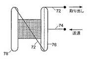
本発明の他の実施形態に従って、閉鎖デバイスは、デバイスの送達、取り出し、又は再位置決めを容易にするため、送達/取り出し機構を具備することができる。図9Aおよび図9Bに示すデバイス70は、取り出しストリング72および送達ストリング74を具備する。取り出しストリングは、近位アンカー部材76の内側に移動可能に固定され、自由に摺動する。ストリングは、近位部材76の一端から延出し、遠位アンカー部材78の反対側の端部に固定されている。取り出しストリング72の自由端を引張ることにより、図9Aに示すように、デバイス70全体を折り畳み、送達シース79の中に引き入れることができる。ストリングは、例えば、縫合糸又はニチノールワイヤなどのワイヤとすることができる。 In accordance with other embodiments of the present invention, the closure device can include a delivery / removal mechanism to facilitate delivery, removal or repositioning of the device. The
デバイスを配備するため又は取り出すため、送達ストリングと取り出しストリングを別々に操作する。図9C〜図9Eは、好ましくは近位アンカー部材76の略中心に取り付けられる送達ストリング74を使用するデバイスの配備を示す。図9Cに示すように、デバイス70を収容する送達シース79を、まず、一次中隔と二次中隔の間に挿入し、左心房に入れる。次いで、図9Dに示すように、送達カテーテル79から遠位アンカー78を放出する。次いで、送達ストリング74に張力を加えて、送達シースを右心房の中に引っ込め、近位アンカー76を放出する。送達ストリングに張力を加えると、近位アンカー76を右心房内に適切に配備することができ、アンカー76が左心房の中に放出されないようになる。デバイス70の配備が成功すると、ストリングを両方とも解放し、送達系を引っ込める。送達中は、取り出しストリングに張力を加えない。 Manipulate the delivery string and the retrieval string separately to deploy or retrieve the device. FIGS. 9C-9E illustrate the deployment of the device using a
図9F〜図9Hは、デバイス70の取り出しを示す。図9Fに示すように、送達シース79をデバイス70の方に移動させる間、取り出しストリングに張力を加える。そのように張力を加えると、図9Gに示すように、近位アンカー76は送達シースの中に引っ込む。取り出しストリングに更に張力を加えると、遠位アンカー78も同様に送達シースの中に引っ込む。次いで、デバイスを必要に応じて再配備するか又は取り出すことができる。 9F-9H show removal of
或いは、送達ストリング74は省くことができ、取り出しストリング72をデバイスの配備と取り出しの両方に使用することができる。図9Cに示すのと同様に、閉鎖デバイスを収容する送達シース79を、まず、一次中隔と二次中隔の間に挿入し、左心房に入れる。次いで、図9Dに示すのと同様に、遠位アンカー78を送達カテーテル79から放出する。取り出しストリング72に張力を加えて送達シースを右心房の中に引っ込め、近位アンカー76を放出する。取り出しストリングに張力を加えると、近位アンカー76を右心房内に適切に配備することができ、近位アンカー76が左心房の中に放出されないようになる。アンカー部材を接続する中心継手の弾性は、近位アンカーを欠損に適切に位置決めするのに役立つ。閉鎖デバイスの配備が成功すると、ストリング72を解放し、送達系を引っ込める。 Alternatively, the
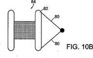
図10Aおよび図10Bに示すように、別の実施形態では、ストリング80(縫合糸、ニチノールワイヤなど)は、閉鎖デバイス84の近位アンカー部材82の両端に取り付けられている。アンカー部材は両方とも可撓性があり、欠損に送達するため又は欠損から取り出すため、図10Aに示すように折り曲げることができる。 As shown in FIGS. 10A and 10B, in another embodiment, strings 80 (sutures, nitinol wire, etc.) are attached to both ends of the
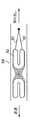
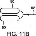
図11Aおよび図11Bに示すように、本発明の別の実施形態に従って、近位および遠位アンカー部材のそれぞれが、弾性ヒンジ92によって分離される2つの要素90を具備することができる。図11Bに示すように、弾性ヒンジ92は、部材の折り曲げを容易にすることができる。ヒンジ92は、要素90とは異なる材料であってもよい材料(例えば、ニチノール又は他の形状記憶材料など)から成形又は製造することができる。 As shown in FIGS. 11A and 11B, in accordance with another embodiment of the present invention, each of the proximal and distal anchor members can comprise two
本発明の幾つかの実施形態に従って、閉鎖デバイス全体を、例えば、図12の閉鎖デバイス100に示すような1枚の材料シートから製造することができる。シートの両端を巻いて、近位アンカー部材と遠位アンカー部材を形成することができる。接着剤又は熱融着を使用して、アンカー部材102、104の巻上げられている形状を維持することができる。 In accordance with some embodiments of the present invention, the entire closure device can be manufactured from a single sheet of material, for example as shown in
図13に示すように、本発明の他の幾つかの実施形態に従って、閉鎖デバイス114のアンカー部材110、112の1つ又は両方を膨張可能とすることができる。デバイスの送達中又は送達前に、アンカー部材を、例えば、塩水又は他の生理学的流体で膨張させることができる。チューブ116は、アンカー部材のキャビティと連通することができる。中に流体を導入するため、部材の1つに入口118を設けることができる。 As shown in FIG. 13, in accordance with some other embodiments of the present invention, one or both of the
本発明の他の幾つかの実施形態に従って、図14に示すように、デバイス126の近位および遠位アンカー部材122、124を接続するため、例えば、S形のワイヤなどのワイヤ120を提供することができる。デバイスがPFO欠損にある時、ワイヤを使用して更なる締め付け力を付与することができる。また、他のワイヤ形状も可能である。 In accordance with some other embodiments of the present invention, a
本発明の他の実施形態に従って、閉鎖デバイスのアンカー部材として1つ以上のフレーム構造を使用することができる。例えば、図15は、フレーム構造132を有する閉鎖デバイス130を示す。また、図16は、フレーム138、139を有する閉鎖デバイス136を示す。フレームは、例えば、金属(例えば、ニチノールワイヤ)又はポリマーフレームとすることができる。 In accordance with other embodiments of the present invention, one or more frame structures can be used as the anchor member of the closure device. For example, FIG. 15 shows a
図17〜図19は、本発明の他の幾つかの実施形態による閉鎖デバイスを示す。図17に示す閉鎖デバイス140は、フレーム構造を有するアンカー部材142、144を具備する。フレーム形状は、図に示すような多角形であっても、又は、或いは円形の形状であってもよい。例えば、図22〜図24に関して後述するように、他のフレーム形状も可能である。 17-19 illustrate a closure device according to some other embodiments of the present invention. The
図18に示すように、カテーテル146に入れて送達するため、又は、回収若しくは再位置決めするため、近位アンカー部材142の両端に回収縫合糸を取り付けてアンカーを折り畳むことができる。アンカー部材は、金属(好ましくは、ニチノール)又はポリマーから製造できる。或いは、図19に示すように、アンカー部材148は金属構成要素とポリマー構成要素の両方を具備することができる。 As shown in FIG. 18, the anchor can be folded with a collection suture attached to both ends of the
本発明の他の1つ以上の実施形態に従って、遠位および近位アンカーは、例えば、図20Aのデバイス170に示すような円筒状の形状を形成するように巻かれる、平坦なシート状の部材で形成することができる。アンカー172、174は、概ね図20Bに示すように、配備されると、巻き出してシート状の部材を形成することができる。シート状の部材は、例えば、形状記憶ポリマー材料などの形状記憶特性を有する材料で製造することができる。或いは、シート状の部材は、例えば、ニチノール又はニチノール合金などの形状記憶金属で製造される金属支柱を具備することができる。形状記憶材料により、アンカーを図20Aの巻かれている形状にして、デバイスを送達シース又はカテーテルに入れて送達することが可能になる。アンカーは、配備されると、その形状記憶特性により、図20Bのシート状の幾何学的形態を達成する。アンカー部材172、174は、接続部材176で互いに接続することができ、接続部材176は、例えば、図2のデバイスに使用されるものに類似の縫合糸とすることができる。 In accordance with one or more other embodiments of the present invention, the distal and proximal anchors are flat sheet-like members that are wound to form a cylindrical shape, for example as shown in
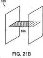
図21Aおよび図21Bは、図20Aおよび図20Bのデバイスのアンカー部材172、174に類似の、巻かれるアンカー部材182、184を有する閉鎖デバイス180を示す。アンカー182、184は、接続部材又は継手186で互いに接続されており、接続部材又は継手186は、図6および図7に関して前述されている接続部材に類似の可撓性材料のシートとすることができる。 FIGS. 21A and 21B show a
図22Aは、本発明の他の1つ以上の実施形態による閉鎖デバイス200を示す。デバイス200は、それぞれが多角形又は円形のフレーム構造を有する遠位および近位アンカー部材202、204を具備する。アンカー部材は、図6および図7と関連して前述されているものに類似の可撓性材料から製造できる接続部材206で接続されている。接続部材206は、中心で接続され、デバイスの側面図で略「X」形を形成する2枚の可撓性材料のシートで製造することができる。図22Bに示すように、近位アンカー部材204は、デバイスの配備又は回収に使用するため、フレーム構造に取り付けられる1つ以上の回収ワイヤ又は縫合糸を具備することができる。図22Cは、配備時のデバイス200を示す。 FIG. 22A illustrates a
図23および図24は、それぞれ、本発明の他の実施形態による閉鎖デバイス220、230を示す。各デバイス220、230は、フレーム構造を有する遠位および近位アンカー部材を具備する。アンカー部材は、図6および図7と関連して前述されているものに類似の可撓性材料から製造できる可撓性継手222で接続されている。図23のデバイス220は、略「+」形を有する遠位および近位アンカー部材224、226を具備する。図24のデバイス230は、略「G」形を有する遠位および近位アンカー部材232、234を具備する。 23 and 24
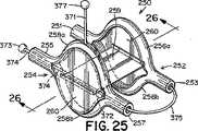
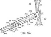
本発明による閉鎖デバイス250の更に別の実施形態では、遠位および/又は近位アンカー部材252および254は、それぞれ、図25〜図27に示すように、長さの中心部分に沿って分割され、細長い楕円形(即ち、「口の開いた」形状)を提供する円筒状の構造で形成されてもよい。この細長い楕円形の形状では、弧256および258は、それぞれ、端部251、253および255、257で接合されている(図25)。この形状によってアンカー部材のサイズおよび表面積が増大し、それによって、閉鎖デバイス250の外れにくさが改善される。本明細書で使用する時、「外れにくさ」は、右心房10と左心房12の間の不等な圧力によって加えられる力(即ち、「外す力」)が中隔組織から閉鎖デバイスを分離させる傾向に抵抗する、閉鎖デバイスの能力を指す。一般に、外れにくいことが望ましい。 In yet another embodiment of the
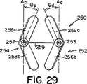
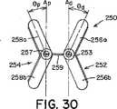
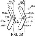
このような細長い楕円形の形状を有する遠位および/又は近位アンカー部材252および254は、二次元(図25〜図27)であっても、又は三次元(図28〜図32)であってもよい。図28に示すように、三次元形状では、近位アンカー部材254の弧258aおよび258bは、二次元近位アンカー部材254の面Aから角度θで屈曲するように、予め配置される。弧258aおよび258bは、中心継手259の方に又は中心継手259から離れるように角度θで屈曲してもよい(それぞれ、図29および図30)。特定の実施形態では、遠位アンカー252と近位アンカー254は両方とも三次元である。このような実施形態では、遠位アンカー部材252の弧256aおよび256b、並びに、近位アンカー部材254の弧258aおよび258bは、同じ角度θで屈曲しても、又はそれぞれ異なる角度θdistalおよびθproximalで屈曲してもよい。更に、弧256a、256b、および、258a、258bは、中心継手259の方に屈曲しても(図29)、中心継手259から離れるように屈曲しても(図30)、又は、反対方向に(即ち、図31に示すように、1つは中心継手259の方に、1つは中心継手259から離れるように)屈曲してもよい。図28〜図32に示すように、弧256a、256b、および、258a、258bは、真直ぐな屈曲を含むが、弧256a、256b、および、258a、258bは、凹状又は凸状になるように、曲線状の屈曲を含んでもよい。更に、当業者には、三次元形状で、端部251、253、および、255、257も、弧256a、256b、および、258a、258bについて前述したように屈曲してよいことが分かる。Distal and / or
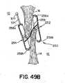
幾つかの臨床用途では、遠位アンカー部材252および/又は近位アンカー部材254の三次元形状が、特に好都合な場合がある。例えば、一次中隔14および二次中隔16は、図32に示すように、典型的には厚さが不同である。そのため、右心房10の中隔組織は、階段状の表面(線LRAで表示する)を特徴とする。また、左心房12の中隔組織も、類似の階段状の表面(線LLAで表示する)を特徴とする場合がある。二次元アンカーを具備する閉鎖デバイスを、このような階段状の中隔組織で取囲まれたPFOに挿入すると、図27に示すように、各アンカー部材の少なくとも1つの弧が中隔組織と接触しないという点で、望ましくない状態にアンカー部材を中隔組織に当てて配置する結果になることが多い。しかし、図32に示すように、三次元アンカー部材の角度のある弧は、中隔組織の階段状の表面によりぴったりと近づく場合がある。このように、ある一定の臨床用途では、三次元遠位アンカー部材252および/又は近位アンカー部材254を具備する閉鎖デバイスを使用すると、改善された状態にデバイス250が中隔組織に当てて配置され、それに対応して、デバイス250のプロファイルが低減し、PFOがより有効に閉鎖される場合がある。本明細書で使用する時、「プロファイル」は、閉鎖デバイス250が中隔組織(即ち、一次中隔14と二次中隔16)から延出し、心房内で露出する程度を指す。「低プロファイル」を有するデバイスは、中隔組織に当ててぴったりと配置され、心房の中に、延出したとしても、僅かだけである。「高プロファイル」を有するデバイスは、中隔組織から延出し、心房の中に入る。一般に、低プロファイルを有するデバイスは生体内での血栓形成性が低いため、低プロファイルを有するデバイスが望ましい。当業者は、三次元アンカー部材の使用が適切な臨床用途を決定することができる。For some clinical applications, the three-dimensional shape of the
図25に示すように、前述の細長い楕円形の形状を有する遠位アンカー部材252および近位アンカー部材254のどちらか又は両方が、それぞれ2つの弧256a、256b、および、258a、258bの間に延在する組織スキャフォールド260を具備してもよい。組織スキャフォールド260を具備すると、アンカー部材252および/又は254によって被覆される中隔組織の面積が増大する。その結果、デバイス250によるPFOの閉鎖が改善される。更に、組織スキャフォールド260は、中隔組織の被包化および内皮化を促進し、それによって、PFOの解剖学的閉鎖が更に促される。組織スキャフォールド260は、以下に限定されないが、ポリエステル布帛、テフロン(登録商標)ベースの材料、ePTFE、ポリウレタン、金属材料、ポリビニルアルコール(PVA)、細胞外基質(ECM)、又は他の生物工学的手法による材料、合成生体吸収性ポリマースキャフォールド、他の天然材料(例えば、コラーゲン)又はこれらの材料の組み合わせを含む、組織の内方成長を促進できる任意の可撓性、生体適合性材料で形成されてもよい。例えば、組織スキャフォールド260は、米国特許出願第2003/0059640号明細書(該特許の内容全体が参照により本明細書に組み込まれる)に記載されるように、例えば、ニチノールフィルムまたは箔などの薄い金属フィルム又は箔で形成されてもよい。 As shown in FIG. 25, either or both of the
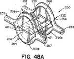
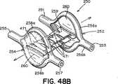
遠位アンカー部材252と近位アンカー部材254を可撓性中心継手259で接続してもよい(図25)。前述のように、少なくとも幾つかの実施形態では、中心継手259は、延伸性エラストマー性材料を含む。少なくとも幾つかの実施形態では、中心継手259は、ポリエステル、生体組織、生体吸収性ポリマー、直径の小さいばね(例えば、ニチノールばね)、海綿状ポリマー材料、又はこれらの材料の組み合わせなどの血栓形成性又は炎症性材料を含む。少なくとも幾つかの実施形態では、中心継手259は、テクスチャ加工されたもの、多孔質、又はベルクロなどの一面若しくは両面フック材料の形態である。これらの種類の表面では炎症反応が起こり、それによって、より速い組織の内方成長と、より速い欠損閉鎖が促進される。特定の実施形態では、図25に示すように、中心継手259は米国特許出願第2002/0165600号明細書および同第2002/0165576号明細書(これらは両方とも、参照により本明細書に組み込まれる)に開示されているものなどの、変形可能な又は伸張可能なフィルムで形成される。例えば、中心継手259は、形状記憶フィルム(例えば、ニチノールフィルム)又はポリマーフィルムで形成されてもよい。生体内に配備する際、フィルムが伸張すると開口部471も伸張するように、フィルムに小さい開口部471(例えば、スリット又は穴など)を切断して設けてもよい(図48Aおよび図48B)。このようにして、中心継手259は、より可撓性が高くなり、閉鎖デバイスに過度の歪みを加えることなく、長さを著しく伸張することができる(図48B)。幾つかの実施形態では、閉鎖デバイス250は、2つの可撓性中心継手259aおよび259bを具備してもよい(図33)。 The
中心継手259は、患者の中隔組織の特定の解剖学的構造に応じて、様々な形状およびサイズを有してもよい。例えば、図25に示すように、中心継手259は、略長方形であってもよい。他の実施形態では、図35に示すように、中心継手259は、弛緩した形状のとき、略「X」又は砂時計の形状に作られてもよい。中心継手259の側部から材料を取り除いて砂時計の形状を形成すると、生体内での可撓性が増大する。砂時計の形状を形成するために、長方形の中心継手259の側部から取り除かれる材料の量は、特定の用途に応じて様々である。幾つかの実施形態によれば、対応する砂時計型の中心継手259を形成するために、長方形の中心継手259の3分の1〜3分の2が取り除かれる。特定の実施形態では、対応する砂時計型の中心継手259を形成するために、長方形の中心継手259の2分の1が取り除かれる。砂時計型の中心継手259を形成するために、長方形の中心継手259の側部から取り除かれる材料の正確な量を決定する際、中心継手259が生体内で接触する中隔組織の治癒反応を促進するのに十分な中心継手259部分が確保されなければならない。当業者は、患者の中隔の解剖学的構造に好適であるが、中隔組織の治癒を促進する中心継手259の能力を十分に維持する砂時計型の中心継手259を形成するために、長方形の中心継手259から取り除き得る材料の正確な量を決定することができる。 The central joint 259 may have various shapes and sizes depending on the specific anatomy of the patient's septal tissue. For example, as shown in FIG. 25, the center joint 259 may be substantially rectangular. In other embodiments, as shown in FIG. 35, the central joint 259 may be made in a generally “X” or hourglass shape when in a relaxed shape. When material is removed from the side of the central joint 259 to form an hourglass shape, in vivo flexibility increases. The amount of material removed from the sides of the rectangular center joint 259 to form an hourglass shape varies depending on the particular application. According to some embodiments, one-third to two-thirds of the rectangular center joint 259 is removed to form a corresponding hourglass-shaped center joint 259. In certain embodiments, one half of the rectangular center joint 259 is removed to form a corresponding hourglass-shaped center joint 259. To determine the exact amount of material removed from the sides of the rectangular central joint 259 to form the hourglass-shaped central joint 259, the central joint 259 promotes the healing response of the septal tissue that contacts it in vivo. Sufficient center joint 259 portion to do this must be ensured. Those skilled in the art will recognize the rectangular shape of the central joint 259 that is suitable for the patient's septal anatomy but sufficiently maintains the ability of the central joint 259 to promote healing of the septal tissue. The exact amount of material that can be removed from the center joint 259 can be determined.
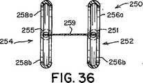
中心継手259は、遠位および近位アンカー部材252および254にそれぞれ接続されても(図35および図36)、又は、存在する場合、組織スキャフォールド260に接続されてもよい(図25)。中心継手259は、組織スキャフォールド260に、その中心で(図25)、周縁部の位置で(図33および図34)で、又はその間のどこかで(図48A)接続してもよい。特定の実施形態では、中心継手259は、角度のあるトンネル状のPFOの解剖学的構造に更にぴったりと近づき、生体内での閉鎖デバイス250のプロファイルが低減する(図48B)ように、遠位アンカー部材252の組織スキャフォールド260の中心と周縁部の間の位置、および、近位アンカー部材254の組織スキャフォールド260の中心と、反対側の周縁部の間の位置で(図48A)接続される。例えば、図48Aおよび図48Bに示すように、中心継手259は、遠位アンカー部材252の組織スキャフォールド260に、組織スキャフォールド260の中心と弧256aの間の位置で接続され、近位アンカー部材254の組織スキャフォールド260に、組織スキャフォールド260の中心と弧258bの間の位置で接続されてもよい。 Center joint 259 may be connected to distal and
細長い楕円形の形状を有する遠位アンカー部材252および/又は近位アンカー部材254を具備する閉鎖デバイスが、送達又は回収カテーテル370内に引き入れられ、収容され得るように、閉鎖デバイス250のプロファイルを低減するように、弧256a、256b、および/又は、258a、258bがそれぞれ折り畳まれる場合、閉鎖デバイスは配備又は回収され得る(図37〜図46)。一実施形態によれば、図25に示すように、閉鎖デバイス250は、送達ストリング371を具備してもよい。図25に示すように、送達ストリング371は、近位アンカー部材254の弧258aに永久的に取り付けられるが、当業者には、送達ストリング371は近位アンカー部材254のどこに取り付けられてもよいことが分かる。送達ストリング371は、任意の好適な方式で、例えば、穴明けされた穴、接着剤などにより取り付けられてもよい。送達ストリング371は短く(即ち、数ミリメートル)、できるだけ血栓形成性が低い。本明細書で使用する時、「ストリング」は、剛性であっても可撓性であってもよい様々な材料を含む。送達ストリング371は、その自由端にあるボール377で終端する。閉鎖デバイス250は、回収ストリング374に取り付けられている回収ボール373を更に具備し、回収ストリング374は、近位アンカー部材254の端部255および257に挿通された後、遠位アンカー部材252の端部253に取り付けられている。遠位アンカー部材252の端部253と、近位アンカー部材254の端部257の間で回収ストリング374のたるみ375が存在する。閉鎖デバイス250は、回収ストリング374に取り付けられ、近位アンカー部材254の端部255と257の間に収容されているボール372を更に具備する。近位アンカー部材254の端部255と257は、内径がボール372の径より大きくてもよいが、端部255と257の終端セグメントの直径がボール372の直径より小さくなるようにテーパが付いている。そのため、ボール372の移動は、近位アンカー部材254の端部255と257の間に拘束される。 The profile of the
生体内に配備する前に、デバイス250を送達カテーテル370に入れなければならない(図37)。図37に示すように、遠位アンカー部材252と近位アンカー部材254との間で回収ストリング374のたるみ375が維持されるように、デバイス250をカテーテル370の中に装填してもよい。例えば、デバイス250を手動でカテーテル370の中に装填してもよい。当業者は、デバイス250をカテーテル370の中に装填する好適な方法を識別できる。 Prior to deployment in vivo,
当業者には、勿論、回収ストリング374のたるみ375の最大量は、ボール372が近位アンカー部材254の端部255と257の間を移動し得る距離に依存することが分かる。ボール372が端部257の終端の方に移動して近付くにつれ、たるみ375は増大する。そのため、端部255と257の内径のテーパを変えることにより、たるみ375の量を調節してもよい。更に、ボール372が近位アンカー部材254内を移動し得る距離、およびそれに対応して、たるみ375が最大になるように、近位アンカー部材254の端部255と257を弧258aと258bに分割するスリット480は端部255と257の終端の方に延びてもよい(図47)。 One skilled in the art will understand that, of course, the maximum amount of
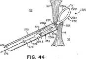
デバイス250は、様々な方法で生体内の意図される送達部位に送達されてもよく、本明細書にそれを1つだけ記載する。図38に示すように、臨床医は、好適なデバイス(例えば、グリップ376および401)で回収ボール373と送達ボール377の両方を保持する。本明細書で使用する時、「ボール」および「グリップ」の用語は、送達機構を総称的に表すのに使用される。当業者には、送達機構の構成要素の正確な構造は様々であってよいことが分かる。グリップ376および401で、臨床医は、デバイス250を適切に操作するのに必要な張力又は圧縮力を送達ストリング371又は回収ストリング374に加えることができる。一般に、本明細書の方法によりデバイス250を送達する間、送達ストリング371だけに張力を加え、回収ストリング374は、たるみ375が維持されるように、弛緩した形状に保つ。臨床医が回収ボール373と送達ボール377を両方とも適切に保持した後、カテーテル370を患者の血管系を通して心臓の右心房10に送達する(図38)。次いで、図39に示すように、カテーテル370を一次中隔14と二次中隔16の間に挿入し、左心房12に入れる。遠位アンカー部材252は、グリップ401を押すことにより左心房12の中に放出され、弧256aおよび256bは、再び細長い楕円形の形状を取る(図39)。近位アンカー部材254が右心房10の中に配備され、たるみ375がPFOを通って延在するように、カテーテル370を一次中隔14と二次中隔16の間に引っ込め、右心房10に入れる(図40)。このプロセス中、グリップ401は送達ボール377に付けたままにして、送達ストリング371に必要な張力を加える(図40)。図40に示すように、近位アンカー部材254を右心房10の中に配備すると、弧258aおよび258bは再び細長い楕円形の形状を取り、必要に応じて、グリップ401を使用して近位アンカー部材254を中隔組織に当てて位置決めしてもよい。遠位アンカー部材252と近位アンカー部材254は協働して、一次中隔14と二次中隔16に圧縮力を加え、それによってPFOを閉鎖する(図41)。閉鎖デバイス250の配備が臨床医に満足であれば、グリップ401から送達ボール377を解放し、グリップ376から回収ボール373を解放し(図41)、カテーテル370を右心房10から引っ込め、更に、患者の血管系を通して引っ込める。 The
しかし、配備後、臨床医がデバイス250の位置に満足でない場合、デバイス250が再位置決め、および/又は、回収され得るように、グリップ376とグリップ401をそれぞれボール373と377に付けたままにしてもよい。グリップ401で送達ストリング371に加えられる張力を更に操作することにより、デバイス250を再位置決めしてもよい(図42)。閉鎖デバイス250を回収するため、カテーテル370を端部255に当てて位置決めする(図43)。ボール372が端部255のB点まで移動するように、回収ボール373をカテーテル370の中に引き入れ、近位アンカー部材254の弧258aおよび258bを折り畳んで、カテーテル370の中に引っ込める(図44)。近位アンカー部材254の完全な回収が近づくと、ストリング374のたるみ375がなくなるか、又は、ほぼなくなり、近位アンカー部材254の端部257および遠位アンカー部材252の端部253が接触するか、又は、ほぼ接触し、近位アンカー部材254と遠位アンカー部材252は縦方向で端と端が接するように整列する(図44)。図45に示すように、グリップ376で回収ストリング374に張力を加え続け、回収ボール373をカテーテル370の近位端の方に引張る。遠位アンカー部材252の弧256aおよび256bを折り畳み、遠位アンカー部材252をカテーテル370の中に引っ込める(図45)。次いで、カテーテル370をPFOを通して引っ込め、右心房10の中に入れる(図46)。 However, if the clinician is not satisfied with the position of the
デバイス250の送達および回収システムを様々に変更してもよく、その1つを図50〜51のデバイス490に示す。ストリング374は、近位アンカー部材254の端部255から弧258aの方に延出し、Y点で弧258に取り付けられ、更に弧258aから延出して送達/回収ストリング491となり、送達/回収ボール492で終端する(図50)。送達/回収ボール492を保持し、送達中、送達/回収ストリング491に加える張力を操作するのに必要なのがグリップ401だけであること以外、デバイス490は、前述のように配備されてもよい。デバイス490を回収するため、グリップ401でY点における近位アンカー部材254の弧258aへの接続を破壊するのに十分な張力を送達/回収ストリング491に加える(図50)。送達/回収ボール492をカテーテル370の近位端の方に引張り、送達/回収ストリング374に張力を更に加えることによって、デバイス490は縦方向を向き、前述のようにカテーテル370の中に引っ込められてもよい。 Various changes may be made to the delivery and retrieval system of
本明細書に記載の閉鎖デバイスは、任意に、縫合又はステープリング法と共に使用することができ、デバイスのアンカー又は可撓性継手を一次中隔14および/又は二次中隔16に縫合又はステープルで固定して、外れにくくすることができる。また、必要に応じて、可撓性継手は、生体適合性接着剤で被覆され組織に接着されてもよく、又は、治癒を促進する薬物若しくは成長因子が装填されてもよい。接着剤、および、ある一定の薬物を任意にアンカー部材252および/又は254(例えば、図6および図7の円筒状の部材)の空洞に貯蔵し、配備後に放出することもできる。また、埋め込み術中、より良好に可視化されるように、放射線不透過性マーカーを閉鎖デバイスに取り付けることもできる。当業者には、X線透視検査および磁気共鳴画像法(MRI)を含む様々な可視化技術を使用してもよいことが分かる。 The closure device described herein can optionally be used with a suturing or stapling method to suture or staple the device's anchor or flexible joint to the
本明細書に記載の様々な閉鎖デバイスは、多数の好都合な特徴を更に具備してもよい。閉鎖デバイスは、配備中又は取り出し中の外傷を低減するため、好ましくは、非外傷性の形状を有する。更に、デバイスは、配備し易いように、自動的に向きが定まるものとすることができる。更に、可撓性中心継手のため、解剖学的構造がデバイスに適合するのではなく、デバイスが解剖学的構造に概ね適合し、これは、長いトンネル欠損にとりわけ有用である。更に、デバイスは、好ましくは、送達中に再位置決めすることができる、および/又は、取り出すことができる。また、デバイスは、配備後、概ね、比較的低いプロファイルを有する。デバイスの可撓性中心継手259は、より速い組織の内方成長、および、従ってより速い欠損閉鎖を促すことができる。更に、左心房12および右心房10には、概ね、露出した血栓形成性の構成要素が存在しない。更にまた、デバイスは、有利には、時間が経つと身体から消失する生体吸収性構成要素を具備してもよい。 The various closure devices described herein may further comprise a number of advantageous features. The closure device preferably has an atraumatic shape to reduce trauma during deployment or removal. In addition, the device can be automatically oriented to facilitate deployment. Furthermore, because of the flexible center joint, the anatomy does not fit the device, but the device generally fits the anatomy, which is particularly useful for long tunnel defects. Furthermore, the device can preferably be repositioned and / or removed during delivery. Also, the device generally has a relatively low profile after deployment. The flexible central joint 259 of the device can facilitate faster tissue ingrowth and thus faster defect closure. Further, the
当業者には、本明細書に記載のいずれかの実施形態の特徴を、本明細書に記載の他のいずれかの実施形態の特徴と組み合わせてもよいことが分かる。 One skilled in the art will appreciate that the features of any embodiment described herein may be combined with the features of any other embodiment described herein.
本明細書に記載のデバイスの他の利点には、比較的直径が小さい送達シースを使用し得ること、デバイスに使用する金属の量の低減若しくは金属の不使用、製造の容易さ、費用効果、および、全体的な設計の単純さが挙げられる。 Other advantages of the devices described herein include the ability to use a relatively small diameter delivery sheath, reduced or no metal used in the device, ease of manufacture, cost effectiveness, And the simplicity of the overall design.
本明細書の好ましい実施形態を記載してきたが、前記の特許請求の範囲に定義される本発明の趣旨および範囲から逸脱することなく、様々な変更をなし得ることは明らかである。 While preferred embodiments of the specification have been described, it will be apparent that various changes can be made without departing from the spirit and scope of the invention as defined in the appended claims.
図面の簡単な説明
Claims (40)
Translated fromJapanese前記中隔組織の一方側に配置されるように構成されている第1の側と、
前記中隔組織の反対側に配置されるように構成されている第2の側と、を備え、
前記第1の側と前記第2の側とは、少なくとも1つの中心継手によって接続され、
前記第1の側と前記第2の側とのそれぞれは、アンカー部材を具備し、
前記第1の側及び前記第2の側の少なくとも一方の前記アンカー部材は、長さの中心部分に沿って分割され、細長い楕円形を形成する略円筒状の部材を備える、デバイス。A device for closing a septal tissue defect,
A first side configured to be disposed on one side of the septal tissue;
A second side configured to be disposed on the opposite side of the septal tissue,
The first side and the second side are connected by at least one central joint,
Each of the first side and the second side comprises an anchor member;
The device, wherein the anchor member on at least one of the first side and the second side comprises a generally cylindrical member that is divided along a central portion of length to form an elongated oval.
前記中隔組織の一方側に配置されるように構成されている第1の側と、
前記中隔組織の反対側に配置されるように構成されている第2の側と、を備え、
前記第1の側と前記第2の側とは、少なくとも1つの中心継手によって接続され、
前記第1の側と前記第2との側のそれぞれが、長さの中心部分に沿って分割され、細長い楕円形を形成する略円筒状の部材を備えるアンカー部材を具備し、
当該デバイスが意図される送達位置に配備されているとき、前記第1の側と前記第2の側とが協働して、前記欠損を取囲む中隔組織に圧縮力を提供する、デバイス。A device for closing a septal tissue defect,
A first side configured to be disposed on one side of the septal tissue;
A second side configured to be disposed on the opposite side of the septal tissue,
The first side and the second side are connected by at least one central joint,
Each of the first side and the second side comprises an anchor member comprising a substantially cylindrical member that is divided along a central portion of length and forms an elongated oval;
The device wherein the first side and the second side cooperate to provide a compressive force on the septal tissue surrounding the defect when the device is deployed in the intended delivery position.
前記第1のアンカー部材の一端から前記第2のアンカー部材まで達し、前記第2のアンカー部材を貫通して延在するストリングと、
前記第2のアンカー部材内で前記ストリングに拘束されているボールと、
を備える、請求項35に記載のデバイス。The recovery mechanism is
A string extending from one end of the first anchor member to the second anchor member and extending through the second anchor member;
A ball constrained to the string in the second anchor member;
36. The device of claim 35, comprising:
Applications Claiming Priority (2)
| Application Number | Priority Date | Filing Date | Title |
|---|---|---|---|
| US10/662,000US7318833B2 (en) | 2001-12-19 | 2003-09-12 | PFO closure device with flexible thrombogenic joint and improved dislodgement resistance |
| PCT/US2004/029978WO2005027752A1 (en) | 2003-09-12 | 2004-09-13 | Pfo closure device with flexible thrombogenic joint and improved dislodgement resistance |
Publications (2)
| Publication Number | Publication Date |
|---|---|
| JP2007504915A JP2007504915A (en) | 2007-03-08 |
| JP4597990B2true JP4597990B2 (en) | 2010-12-15 |
Family
ID=34375793
Family Applications (1)
| Application Number | Title | Priority Date | Filing Date |
|---|---|---|---|
| JP2006526395AExpired - Fee RelatedJP4597990B2 (en) | 2003-09-12 | 2004-09-13 | PFO closure device with flexible thrombogenic joint and improved detachability |
Country Status (5)
| Country | Link |
|---|---|
| US (3) | US7318833B2 (en) |
| EP (1) | EP1680026A1 (en) |
| JP (1) | JP4597990B2 (en) |
| CA (1) | CA2538321A1 (en) |
| WO (1) | WO2005027752A1 (en) |
Families Citing this family (192)
| Publication number | Priority date | Publication date | Assignee | Title |
|---|---|---|---|---|
| EP1685808B1 (en) | 1998-01-30 | 2016-09-14 | St.Jude Medical ATG, Inc. | Device for use in closing septal defects and an installation assembly for such device |
| US7662161B2 (en) | 1999-09-13 | 2010-02-16 | Rex Medical, L.P | Vascular hole closure device |
| US6846319B2 (en) | 2000-12-14 | 2005-01-25 | Core Medical, Inc. | Devices for sealing openings through tissue and apparatus and methods for delivering them |
| US6896692B2 (en) | 2000-12-14 | 2005-05-24 | Ensure Medical, Inc. | Plug with collet and apparatus and method for delivering such plugs |
| US6890343B2 (en) | 2000-12-14 | 2005-05-10 | Ensure Medical, Inc. | Plug with detachable guidewire element and methods for use |
| US8083768B2 (en) | 2000-12-14 | 2011-12-27 | Ensure Medical, Inc. | Vascular plug having composite construction |
| US6623509B2 (en) | 2000-12-14 | 2003-09-23 | Core Medical, Inc. | Apparatus and methods for sealing vascular punctures |
| US8091556B2 (en) | 2001-04-20 | 2012-01-10 | V-Wave Ltd. | Methods and apparatus for reducing localized circulatory system pressure |
| US7338514B2 (en) | 2001-06-01 | 2008-03-04 | St. Jude Medical, Cardiology Division, Inc. | Closure devices, related delivery methods and tools, and related methods of use |
| US7288105B2 (en) | 2001-08-01 | 2007-10-30 | Ev3 Endovascular, Inc. | Tissue opening occluder |
| US6702835B2 (en) | 2001-09-07 | 2004-03-09 | Core Medical, Inc. | Needle apparatus for closing septal defects and methods for using such apparatus |
| US20050267495A1 (en)* | 2004-05-17 | 2005-12-01 | Gateway Medical, Inc. | Systems and methods for closing internal tissue defects |
| US6776784B2 (en)* | 2001-09-06 | 2004-08-17 | Core Medical, Inc. | Clip apparatus for closing septal defects and methods of use |
| US20060052821A1 (en) | 2001-09-06 | 2006-03-09 | Ovalis, Inc. | Systems and methods for treating septal defects |
| US20070112338A1 (en)* | 2005-11-01 | 2007-05-17 | Microfabrica Inc. | Microdevices for tissue approximation and retention, methods for using, and methods for making |
| US20070198038A1 (en)* | 2001-12-03 | 2007-08-23 | Cohen Adam L | Microdevices for Tissue Approximation and Retention, Methods for Using, and Methods for Making |
| US7318833B2 (en)* | 2001-12-19 | 2008-01-15 | Nmt Medical, Inc. | PFO closure device with flexible thrombogenic joint and improved dislodgement resistance |
| EP1467661A4 (en)* | 2001-12-19 | 2008-11-05 | Nmt Medical Inc | Septal occluder and associated methods |
| US7147661B2 (en) | 2001-12-20 | 2006-12-12 | Boston Scientific Santa Rosa Corp. | Radially expandable stent |
| JP2005521447A (en) | 2002-03-25 | 2005-07-21 | エヌエムティー メディカル インコーポレイテッド | Closure clip of patent foramen ovale (PFO) |
| US7976564B2 (en) | 2002-05-06 | 2011-07-12 | St. Jude Medical, Cardiology Division, Inc. | PFO closure devices and related methods of use |
| AU2003240549A1 (en) | 2002-06-05 | 2003-12-22 | Nmt Medical, Inc. | Patent foramen ovale (pfo) closure device with radial and circumferential support |
| EP1556117A1 (en) | 2002-10-25 | 2005-07-27 | NMT Medical, Inc. | Expandable sheath tubing |
| US8454652B1 (en) | 2002-10-29 | 2013-06-04 | Adam L. Cohen | Releasable tissue anchoring device, methods for using, and methods for making |
| US20110092988A1 (en)* | 2002-10-29 | 2011-04-21 | Microfabrica Inc. | Microdevices for Tissue Approximation and Retention, Methods for Using, and Methods for Making |
| WO2004052213A1 (en) | 2002-12-09 | 2004-06-24 | Nmt Medical, Inc. | Septal closure devices |
| EP1596723A2 (en) | 2003-02-04 | 2005-11-23 | ev3 Sunnyvale, Inc. | Patent foramen ovale closure system |
| US20040267306A1 (en) | 2003-04-11 | 2004-12-30 | Velocimed, L.L.C. | Closure devices, related delivery methods, and related methods of use |
| US8372112B2 (en) | 2003-04-11 | 2013-02-12 | St. Jude Medical, Cardiology Division, Inc. | Closure devices, related delivery methods, and related methods of use |
| US7122043B2 (en)* | 2003-05-19 | 2006-10-17 | Stout Medical Group, L.P. | Tissue distention device and related methods for therapeutic intervention |
| US9861346B2 (en) | 2003-07-14 | 2018-01-09 | W. L. Gore & Associates, Inc. | Patent foramen ovale (PFO) closure device with linearly elongating petals |
| EP2481356B1 (en)* | 2003-07-14 | 2013-09-11 | W.L. Gore & Associates, Inc. | Tubular patent foramen ovale (PFO) closure device with catch system |
| US8480706B2 (en) | 2003-07-14 | 2013-07-09 | W.L. Gore & Associates, Inc. | Tubular patent foramen ovale (PFO) closure device with catch system |
| CA2536368A1 (en) | 2003-08-19 | 2005-03-03 | Nmt Medical, Inc. | Expandable sheath tubing |
| US20050192627A1 (en)* | 2003-10-10 | 2005-09-01 | Whisenant Brian K. | Patent foramen ovale closure devices, delivery apparatus and related methods and systems |
| EP1680027A2 (en)* | 2003-10-10 | 2006-07-19 | Proximare, Inc. | Patent foramen ovale (pfo) closure devices, delivery apparatus and related methods and systems |
| US7361183B2 (en) | 2003-10-17 | 2008-04-22 | Ensure Medical, Inc. | Locator and delivery device and method of use |
| US8852229B2 (en) | 2003-10-17 | 2014-10-07 | Cordis Corporation | Locator and closure device and method of use |
| US7056286B2 (en) | 2003-11-12 | 2006-06-06 | Adrian Ravenscroft | Medical device anchor and delivery system |
| US20050273119A1 (en) | 2003-12-09 | 2005-12-08 | Nmt Medical, Inc. | Double spiral patent foramen ovale closure clamp |
| CA2551531C (en)* | 2003-12-26 | 2015-02-24 | Terumo Kabushiki Kaisha | Tissue closure and tissue closing device |
| JP2007527742A (en) | 2004-02-03 | 2007-10-04 | アトリア メディカル インク | Apparatus and method for controlling pressure in a living body |
| US20050187565A1 (en) | 2004-02-20 | 2005-08-25 | Baker Steve G. | Tissue fixation devices and a transoral endoscopic gastroesophageal flap valve restoration device and assembly using same |
| US7632287B2 (en) | 2004-02-20 | 2009-12-15 | Endogastric Solutions, Inc. | Tissue fixation devices and assemblies for deploying the same |
| EP1737349A1 (en) | 2004-03-03 | 2007-01-03 | NMT Medical, Inc. | Delivery/recovery system for septal occluder |
| US20050267524A1 (en) | 2004-04-09 | 2005-12-01 | Nmt Medical, Inc. | Split ends closure device |
| US8361110B2 (en) | 2004-04-26 | 2013-01-29 | W.L. Gore & Associates, Inc. | Heart-shaped PFO closure device |
| US8308760B2 (en)* | 2004-05-06 | 2012-11-13 | W.L. Gore & Associates, Inc. | Delivery systems and methods for PFO closure device with two anchors |
| US7842053B2 (en) | 2004-05-06 | 2010-11-30 | Nmt Medical, Inc. | Double coil occluder |
| EP1748732A1 (en) | 2004-05-07 | 2007-02-07 | NMT Medical, Inc. | Catching mechanisms for tubular septal occluder |
| EP1827247B8 (en) | 2004-09-24 | 2020-05-06 | W.L. Gore & Associates, Inc. | Occluder device double securement system for delivery/recovery of such occluder device |
| GB0425296D0 (en)* | 2004-11-17 | 2004-12-15 | Grampian Health Board | Tissue anchor |
| US20060116697A1 (en) | 2004-11-30 | 2006-06-01 | Esophyx, Inc. | Flexible transoral endoscopic gastroesophageal flap valve restoration device and method |
| JP4366306B2 (en)* | 2004-12-17 | 2009-11-18 | テルモ株式会社 | In vivo tissue closure device and in vivo tissue closure device |
| US20060167481A1 (en) | 2005-01-25 | 2006-07-27 | Esophyx, Inc. | Slitted tissue fixation devices and assemblies for deploying the same |
| JP5030797B2 (en) | 2005-02-07 | 2012-09-19 | アイビー スポーツ メディシン、エルエルシー | System and method for fully internal suture fixation of implant placement and soft tissue repair |
| US8128640B2 (en) | 2005-02-07 | 2012-03-06 | Ivy Sports Medicine LLC | System and method for all-inside suture fixation for implant attachment and soft tissue repair |
| WO2006102213A1 (en) | 2005-03-18 | 2006-09-28 | Nmt Medical, Inc. | Catch member for pfo occluder |
| US7321798B2 (en)* | 2005-03-31 | 2008-01-22 | Medtronic, Inc. | Trans-septal/trans-myocardial ventricular pacing lead |
| JP5058969B2 (en)* | 2005-04-06 | 2012-10-24 | ボストン サイエンティフィック リミテッド | System, apparatus and method for suburethral support |
| US8088144B2 (en) | 2005-05-04 | 2012-01-03 | Ensure Medical, Inc. | Locator and closure device and method of use |
| US8926654B2 (en) | 2005-05-04 | 2015-01-06 | Cordis Corporation | Locator and closure device and method of use |
| EP2135560B1 (en) | 2005-06-02 | 2011-08-10 | Cordis Corporation | Medical device for deploying a mechanical closure devcie |
| US20070005082A1 (en) | 2005-06-29 | 2007-01-04 | Esophyx, Inc. | Apparatus and method for manipulating stomach tissue and treating gastroesophageal reflux disease |
| US8579936B2 (en) | 2005-07-05 | 2013-11-12 | ProMed, Inc. | Centering of delivery devices with respect to a septal defect |
| US20070038232A1 (en) | 2005-08-12 | 2007-02-15 | Kraemer Stefan J M | Apparatus and method for securing the stomach to the diaphragm for use, for example, in treating hiatal hernias and gastroesophageal reflux disease |
| US7998095B2 (en)* | 2005-08-19 | 2011-08-16 | Boston Scientific Scimed, Inc. | Occlusion device |
| US7824397B2 (en)* | 2005-08-19 | 2010-11-02 | Boston Scientific Scimed, Inc. | Occlusion apparatus |
| US7766906B2 (en)* | 2005-08-19 | 2010-08-03 | Boston Scientific Scimed, Inc. | Occlusion apparatus |
| US8062309B2 (en)* | 2005-08-19 | 2011-11-22 | Boston Scientific Scimed, Inc. | Defect occlusion apparatus, system, and method |
| US7837619B2 (en)* | 2005-08-19 | 2010-11-23 | Boston Scientific Scimed, Inc. | Transeptal apparatus, system, and method |
| US7846179B2 (en) | 2005-09-01 | 2010-12-07 | Ovalis, Inc. | Suture-based systems and methods for treating septal defects |
| CA2621197A1 (en)* | 2005-09-01 | 2007-03-08 | Cordis Corporation | Patent foramen ovale closure method |
| US20070056591A1 (en)* | 2005-09-15 | 2007-03-15 | Mcswain Hugh | Fallopian tube occlusion devices and methods |
| US9943296B2 (en)* | 2005-09-20 | 2018-04-17 | Rob K. Rao | Surgical method and clamping apparatus for repair of a defect in a dural membrane or a vascular wall, and anastomic method and apparatus for a body lumen |
| US20070088373A1 (en) | 2005-10-18 | 2007-04-19 | Endogastric Solutions, Inc. | Invaginator for gastroesophageal flap valve restoration device |
| US9161754B2 (en) | 2012-12-14 | 2015-10-20 | Endogastric Solutions, Inc. | Apparatus and method for concurrently forming a gastroesophageal valve and tightening the lower esophageal sphincter |
| US20070167981A1 (en) | 2005-12-22 | 2007-07-19 | Nmt Medical, Inc. | Catch members for occluder devices |
| WO2007083288A2 (en) | 2006-01-23 | 2007-07-26 | Atria Medical Inc. | Heart anchor device |
| US8162974B2 (en)* | 2006-02-02 | 2012-04-24 | Boston Scientific Scimed, Inc. | Occlusion apparatus, system, and method |
| US20070225756A1 (en)* | 2006-03-22 | 2007-09-27 | Radi Medical Systems Ab | Closure device and insertion assembly |
| US20070225757A1 (en)* | 2006-03-22 | 2007-09-27 | Radi Medical Systems Ab | Closure device |
| US20070225755A1 (en)* | 2006-03-22 | 2007-09-27 | Radi Medical Systems Ab | Closure device |
| US20090036919A1 (en)* | 2006-03-22 | 2009-02-05 | Radi Medical Systems Ab | Closure device |
| US20070225758A1 (en)* | 2006-03-22 | 2007-09-27 | Radi Medical Systems Ab | Closure device |
| US20090030450A1 (en)* | 2006-03-22 | 2009-01-29 | Radi Medical Systems Ab | Closure device |
| US8814947B2 (en) | 2006-03-31 | 2014-08-26 | W.L. Gore & Associates, Inc. | Deformable flap catch mechanism for occluder device |
| US8870913B2 (en) | 2006-03-31 | 2014-10-28 | W.L. Gore & Associates, Inc. | Catch system with locking cap for patent foramen ovale (PFO) occluder |
| US8551135B2 (en) | 2006-03-31 | 2013-10-08 | W.L. Gore & Associates, Inc. | Screw catch mechanism for PFO occluder and method of use |
| US9220487B2 (en)* | 2006-08-09 | 2015-12-29 | Coherex Medical, Inc. | Devices for reducing the size of an internal tissue opening |
| US8529597B2 (en) | 2006-08-09 | 2013-09-10 | Coherex Medical, Inc. | Devices for reducing the size of an internal tissue opening |
| US8167894B2 (en) | 2006-08-09 | 2012-05-01 | Coherex Medical, Inc. | Methods, systems and devices for reducing the size of an internal tissue opening |
| US8075576B2 (en)* | 2006-08-24 | 2011-12-13 | Boston Scientific Scimed, Inc. | Closure device, system, and method |
| US8894682B2 (en) | 2006-09-11 | 2014-11-25 | Boston Scientific Scimed, Inc. | PFO clip |
| WO2008036384A2 (en)* | 2006-09-21 | 2008-03-27 | Synecor, Llc | Stomach wall closure devices |
| US20080077180A1 (en)* | 2006-09-26 | 2008-03-27 | Nmt Medical, Inc. | Scaffold for tubular septal occluder device and techniques for attachment |
| US8029532B2 (en)* | 2006-10-11 | 2011-10-04 | Cook Medical Technologies Llc | Closure device with biomaterial patches |
| US10413284B2 (en) | 2006-11-07 | 2019-09-17 | Corvia Medical, Inc. | Atrial pressure regulation with control, sensing, monitoring and therapy delivery |
| US8460372B2 (en) | 2006-11-07 | 2013-06-11 | Dc Devices, Inc. | Prosthesis for reducing intra-cardiac pressure having an embolic filter |
| EP2097012A4 (en) | 2006-11-07 | 2012-08-15 | David Stephen Celermajer | Devices and methods for the treatment of heart failure |
| US20110257723A1 (en) | 2006-11-07 | 2011-10-20 | Dc Devices, Inc. | Devices and methods for coronary sinus pressure relief |
| US9232997B2 (en) | 2006-11-07 | 2016-01-12 | Corvia Medical, Inc. | Devices and methods for retrievable intra-atrial implants |
| DE102006054218A1 (en)* | 2006-11-15 | 2008-05-21 | Karl Storz Medizinische Nähsysteme GmbH & Co. KG | Surgical instrument for closing an incision in the human body |
| WO2008085994A2 (en) | 2007-01-08 | 2008-07-17 | Endogastric Solutions | Connected fasteners, delivery device and method |
| US8617205B2 (en) | 2007-02-01 | 2013-12-31 | Cook Medical Technologies Llc | Closure device |
| US20080188892A1 (en)* | 2007-02-01 | 2008-08-07 | Cook Incorporated | Vascular occlusion device |
| WO2008094706A2 (en)* | 2007-02-01 | 2008-08-07 | Cook Incorporated | Closure device and method of closing a bodily opening |
| WO2008094691A2 (en)* | 2007-02-01 | 2008-08-07 | Cook Incorporated | Closure device and method for occluding a bodily passageway |
| US9005242B2 (en) | 2007-04-05 | 2015-04-14 | W.L. Gore & Associates, Inc. | Septal closure device with centering mechanism |
| US9138562B2 (en) | 2007-04-18 | 2015-09-22 | W.L. Gore & Associates, Inc. | Flexible catheter system |
| US8915958B2 (en)* | 2007-06-08 | 2014-12-23 | St. Jude Medical, Inc. | Devices for transcatheter prosthetic heart valve implantation and access closure |
| US9492149B2 (en)* | 2007-11-13 | 2016-11-15 | Cook Biotech Incorporated | Fistula grafts and related methods and systems useful for treating gastrointestinal and other fistulae |
| US8491629B2 (en) | 2008-02-15 | 2013-07-23 | Rex Medical | Vascular hole closure delivery device |
| US8070772B2 (en)* | 2008-02-15 | 2011-12-06 | Rex Medical, L.P. | Vascular hole closure device |
| US8920462B2 (en) | 2008-02-15 | 2014-12-30 | Rex Medical, L.P. | Vascular hole closure device |
| US8920463B2 (en) | 2008-02-15 | 2014-12-30 | Rex Medical, L.P. | Vascular hole closure device |
| US20110029013A1 (en) | 2008-02-15 | 2011-02-03 | Mcguckin James F | Vascular Hole Closure Device |
| US9226738B2 (en) | 2008-02-15 | 2016-01-05 | Rex Medical, L.P. | Vascular hole closure delivery device |
| US9138213B2 (en)* | 2008-03-07 | 2015-09-22 | W.L. Gore & Associates, Inc. | Heart occlusion devices |
| US9119607B2 (en) | 2008-03-07 | 2015-09-01 | Gore Enterprise Holdings, Inc. | Heart occlusion devices |
| US20130165967A1 (en) | 2008-03-07 | 2013-06-27 | W.L. Gore & Associates, Inc. | Heart occlusion devices |
| US20090264920A1 (en)* | 2008-03-31 | 2009-10-22 | Alejandro Berenstein | Catheter-based septal occlusion device and adhesive delivery system |
| AU2009324819B2 (en)* | 2008-12-09 | 2014-04-17 | Cook Medical Technologies Llc | Retractable tacking device |
| US9913634B2 (en)* | 2009-02-20 | 2018-03-13 | Boston Scientific Scimed, Inc. | Locking element for vascular closure device |
| US8906037B2 (en) | 2009-03-18 | 2014-12-09 | Endogastric Solutions, Inc. | Methods and devices for forming a tissue fold |
| US10076403B1 (en) | 2009-05-04 | 2018-09-18 | V-Wave Ltd. | Shunt for redistributing atrial blood volume |
| US20210161637A1 (en) | 2009-05-04 | 2021-06-03 | V-Wave Ltd. | Shunt for redistributing atrial blood volume |
| US12186176B2 (en) | 2009-05-04 | 2025-01-07 | V-Wave Ltd. | Shunt for redistributing atrial blood volume |
| US9034034B2 (en) | 2010-12-22 | 2015-05-19 | V-Wave Ltd. | Devices for reducing left atrial pressure, and methods of making and using same |
| WO2010128501A1 (en) | 2009-05-04 | 2010-11-11 | V-Wave Ltd. | Device and method for regulating pressure in a heart chamber |
| CH701269A1 (en) | 2009-06-10 | 2010-12-15 | Carag Ag | Occluder. |
| US9636094B2 (en) | 2009-06-22 | 2017-05-02 | W. L. Gore & Associates, Inc. | Sealing device and delivery system |
| US20120029556A1 (en) | 2009-06-22 | 2012-02-02 | Masters Steven J | Sealing device and delivery system |
| US9757107B2 (en) | 2009-09-04 | 2017-09-12 | Corvia Medical, Inc. | Methods and devices for intra-atrial shunts having adjustable sizes |
| US10092427B2 (en) | 2009-11-04 | 2018-10-09 | Confluent Medical Technologies, Inc. | Alternating circumferential bridge stent design and methods for use thereof |
| EP2528646A4 (en) | 2010-01-29 | 2017-06-28 | DC Devices, Inc. | Devices and systems for treating heart failure |
| WO2011094521A2 (en) | 2010-01-29 | 2011-08-04 | Dc Devices, Inc. | Devices and methods for reducing venous pressure |
| US9795482B2 (en)* | 2010-04-27 | 2017-10-24 | Medtronic, Inc. | Prosthetic heart valve devices and methods of valve repair |
| WO2012047308A1 (en) | 2010-10-08 | 2012-04-12 | Nitinol Devices And Components, Inc. | Alternating circumferential bridge stent design and methods for use thereof |
| EP2627265B8 (en) | 2010-10-15 | 2019-02-20 | Cook Medical Technologies LLC | Occlusion device for blocking fluid flow through bodily passages |
| WO2012109557A2 (en) | 2011-02-10 | 2012-08-16 | Dc Devices, Inc. | Apparatus and methods to create and maintain an intra-atrial pressure relief opening |
| US12303119B2 (en) | 2011-02-10 | 2025-05-20 | Corvia Medical, Inc. | Apparatus and methods to create and maintain an intra-atrial pressure relief opening |
| AU2012225575B9 (en) | 2011-03-08 | 2015-08-20 | W. L. Gore & Associates, Inc. | Medical device for use with a stoma |
| US9629715B2 (en) | 2011-07-28 | 2017-04-25 | V-Wave Ltd. | Devices for reducing left atrial pressure having biodegradable constriction, and methods of making and using same |
| US11135054B2 (en) | 2011-07-28 | 2021-10-05 | V-Wave Ltd. | Interatrial shunts having biodegradable material, and methods of making and using same |
| US9770232B2 (en) | 2011-08-12 | 2017-09-26 | W. L. Gore & Associates, Inc. | Heart occlusion devices |
| US20130066338A1 (en) | 2011-09-09 | 2013-03-14 | Richard Romley | Methods and devices for manipulating and fastening tissue |
| US9572571B2 (en) | 2011-09-09 | 2017-02-21 | Endogastric Solutions, Inc. | Methods and devices for manipulating and fastening tissue |
| US9955957B2 (en) | 2011-09-09 | 2018-05-01 | Endogastric Solutions, Inc. | Methods and devices for manipulating and fastening tissue |
| US8951223B2 (en) | 2011-12-22 | 2015-02-10 | Dc Devices, Inc. | Methods and devices for intra-atrial shunts having adjustable sizes |
| US9005155B2 (en) | 2012-02-03 | 2015-04-14 | Dc Devices, Inc. | Devices and methods for treating heart failure |
| US10588611B2 (en) | 2012-04-19 | 2020-03-17 | Corvia Medical Inc. | Implant retention attachment and method of use |
| US9649480B2 (en) | 2012-07-06 | 2017-05-16 | Corvia Medical, Inc. | Devices and methods of treating or ameliorating diastolic heart failure through pulmonary valve intervention |
| US10039536B2 (en) | 2012-11-16 | 2018-08-07 | W. L. Gore & Associates, Inc. | Implantable medical device deployment system |
| US9757106B2 (en) | 2012-12-03 | 2017-09-12 | Cook Medical Technologies Llc | Degradable expanding closure plug |
| US10828019B2 (en) | 2013-01-18 | 2020-11-10 | W.L. Gore & Associates, Inc. | Sealing device and delivery system |
| CN104905828B (en)* | 2013-02-04 | 2018-08-07 | 先健科技(深圳)有限公司 | A kind of plugging device of the flat disk with included-angle-changeable |
| US9775636B2 (en) | 2013-03-12 | 2017-10-03 | Corvia Medical, Inc. | Devices, systems, and methods for treating heart failure |
| CN104812315B (en)* | 2013-05-15 | 2017-05-03 | 郡是株式会社 | Medical Materials |
| EP2999412B1 (en) | 2013-05-21 | 2020-05-06 | V-Wave Ltd. | Apparatus for delivering devices for reducing left atrial pressure |
| US10675450B2 (en) | 2014-03-12 | 2020-06-09 | Corvia Medical, Inc. | Devices and methods for treating heart failure |
| US9813558B1 (en) | 2014-04-11 | 2017-11-07 | United Services Automobile Association (Usaa) | Systems and methods relating to caller-centric call data |
| US11439396B2 (en) | 2014-05-02 | 2022-09-13 | W. L. Gore & Associates, Inc. | Occluder and anastomosis devices |
| US10363040B2 (en) | 2014-05-02 | 2019-07-30 | W. L. Gore & Associates, Inc. | Anastomosis devices |
| US11712230B2 (en) | 2014-05-02 | 2023-08-01 | W. L. Gore & Associates, Inc. | Occluder and anastomosis devices |
| US9808230B2 (en) | 2014-06-06 | 2017-11-07 | W. L. Gore & Associates, Inc. | Sealing device and delivery system |
| JP6799526B2 (en) | 2014-07-23 | 2020-12-16 | コルヴィア メディカル インコーポレイテッド | Equipment and methods for the treatment of heart failure |
| EP3291773A4 (en) | 2015-05-07 | 2019-05-01 | The Medical Research, Infrastructure, And Health Services Fund Of The Tel Aviv Medical Center | TEMPORARY INTERAURICULAR SHUNTS |
| US10265059B2 (en) | 2016-02-04 | 2019-04-23 | Edwards Lifesciences Corporation | Trans-septal closure and port device |
| US10932769B2 (en) | 2016-05-26 | 2021-03-02 | Ivy Sports Medicine, Llc | System and method for all-inside suture fixation for implant attachment and soft tissue repair |
| US10835394B2 (en) | 2016-05-31 | 2020-11-17 | V-Wave, Ltd. | Systems and methods for making encapsulated hourglass shaped stents |
| US20170340460A1 (en) | 2016-05-31 | 2017-11-30 | V-Wave Ltd. | Systems and methods for making encapsulated hourglass shaped stents |
| WO2018158747A1 (en) | 2017-03-03 | 2018-09-07 | V-Wave Ltd. | Shunt for redistributing atrial blood volume |
| US11291807B2 (en) | 2017-03-03 | 2022-04-05 | V-Wave Ltd. | Asymmetric shunt for redistributing atrial blood volume |
| US11724075B2 (en) | 2017-04-18 | 2023-08-15 | W. L. Gore & Associates, Inc. | Deployment constraining sheath that enables staged deployment by device section |
| US10993807B2 (en) | 2017-11-16 | 2021-05-04 | Medtronic Vascular, Inc. | Systems and methods for percutaneously supporting and manipulating a septal wall |
| WO2019142152A1 (en) | 2018-01-20 | 2019-07-25 | V-Wave Ltd. | Devices and methods for providing passage between heart chambers |
| US11458287B2 (en) | 2018-01-20 | 2022-10-04 | V-Wave Ltd. | Devices with dimensions that can be reduced and increased in vivo, and methods of making and using the same |
| US10898698B1 (en) | 2020-05-04 | 2021-01-26 | V-Wave Ltd. | Devices with dimensions that can be reduced and increased in vivo, and methods of making and using the same |
| JP2022517224A (en)* | 2019-01-14 | 2022-03-07 | ヴァルフィックス メディカル リミテッド | Anchors and locks for percutaneous valve implants |
| US11504105B2 (en) | 2019-01-25 | 2022-11-22 | Rex Medical L.P. | Vascular hole closure device |
| US11612385B2 (en) | 2019-04-03 | 2023-03-28 | V-Wave Ltd. | Systems and methods for delivering implantable devices across an atrial septum |
| US12226602B2 (en) | 2019-04-03 | 2025-02-18 | V-Wave Ltd. | Systems for delivering implantable devices across an atrial septum |
| EP3972499A1 (en) | 2019-05-20 | 2022-03-30 | V-Wave Ltd. | Systems and methods for creating an interatrial shunt |
| JP2022544920A (en)* | 2019-08-08 | 2022-10-24 | トランスミューラル システムズ エルエルシー | Cross-tissue system and anchor for use therewith |
| WO2021151026A1 (en)* | 2020-01-24 | 2021-07-29 | PatchClamp Medtech, Inc. | Tissue repair and sealing devices having a detachable graft and clasp assembly and methods for the use thereof |
| JP6928399B1 (en)* | 2020-06-22 | 2021-09-01 | ネットビジネスコンサルティング株式会社 | Blocking device and manufacturing method of blocking device |
| CN116847790A (en)* | 2020-11-02 | 2023-10-03 | 瑞科罗斯有氧运动公司 | Interval obturator device |
| US11234702B1 (en) | 2020-11-13 | 2022-02-01 | V-Wave Ltd. | Interatrial shunt having physiologic sensor |
| EP4035606A3 (en)* | 2021-01-29 | 2022-08-10 | St. Jude Medical, Cardiology Division, Inc. | Medical device for closure of a vascular abnormality |
| AU2023252664A1 (en) | 2022-04-14 | 2024-10-17 | V-Wave Ltd. | Interatrial shunt with expanded neck region |
| US12296122B2 (en) | 2023-10-18 | 2025-05-13 | V-Wave Ltd. | Hybrid devices with dimensions that can be adjusted in vivo and methods of manufacturing thereof |
Family Cites Families (281)
| Publication number | Priority date | Publication date | Assignee | Title |
|---|---|---|---|---|
| US626245A (en)* | 1899-06-06 | James ricks | ||
| DE1445746A1 (en) | 1964-01-04 | 1969-03-20 | Bayer Ag | Process for the production of asymmetrical thiol or thionothiolphosphoric acid esters |
| US3874388A (en)* | 1973-02-12 | 1975-04-01 | Ochsner Med Found Alton | Shunt defect closure system |
| US3875648A (en)* | 1973-04-04 | 1975-04-08 | Dennison Mfg Co | Fastener attachment apparatus and method |
| US3824631A (en) | 1973-05-11 | 1974-07-23 | Sampson Corp | Bone joint fusion prosthesis |
| US3924631A (en) | 1973-12-06 | 1975-12-09 | Altair Inc | Magnetic clamp |
| US4006747A (en)* | 1975-04-23 | 1977-02-08 | Ethicon, Inc. | Surgical method |
| US4007743A (en)* | 1975-10-20 | 1977-02-15 | American Hospital Supply Corporation | Opening mechanism for umbrella-like intravascular shunt defect closure device |
| CH598398A5 (en) | 1976-07-21 | 1978-04-28 | Jura Elektroapparate Fab | |
| US4235238A (en) | 1978-05-11 | 1980-11-25 | Olympus Optical Co., Ltd. | Apparatus for suturing coeliac tissues |
| US4425908A (en)* | 1981-10-22 | 1984-01-17 | Beth Israel Hospital | Blood clot filter |
| JPS6171065A (en) | 1984-09-13 | 1986-04-11 | テルモ株式会社 | Catheter introducer |
| US4696300A (en) | 1985-04-11 | 1987-09-29 | Dennison Manufacturing Company | Fastener for joining materials |
| US4626245A (en) | 1985-08-30 | 1986-12-02 | Cordis Corporation | Hemostatis valve comprising an elastomeric partition having opposed intersecting slits |
| US4710192A (en) | 1985-12-30 | 1987-12-01 | Liotta Domingo S | Diaphragm and method for occlusion of the descending thoracic aorta |
| DE3774781D1 (en) | 1986-07-16 | 1992-01-09 | Sumitomo Chemical Co | RUBBER BLEND. |
| US4852568A (en) | 1987-02-17 | 1989-08-01 | Kensey Nash Corporation | Method and apparatus for sealing an opening in tissue of a living being |
| US5478353A (en) | 1987-05-14 | 1995-12-26 | Yoon; Inbae | Suture tie device system and method for suturing anatomical tissue proximate an opening |
| US5250430A (en) | 1987-06-29 | 1993-10-05 | Massachusetts Institute Of Technology | Polyhydroxyalkanoate polymerase |
| US5245023A (en) | 1987-06-29 | 1993-09-14 | Massachusetts Institute Of Technology | Method for producing novel polyester biopolymers |
| US4836204A (en)* | 1987-07-06 | 1989-06-06 | Landymore Roderick W | Method for effecting closure of a perforation in the septum of the heart |
| US4840623A (en)* | 1988-02-01 | 1989-06-20 | Fbk International Corporation | Medical catheter with splined internal wall |
| IT1216042B (en)* | 1988-03-09 | 1990-02-22 | Carlo Rebuffat | AUTOMATIC TOOL FOR TOBACCO BAG SUTURES FOR SURGICAL USE. |
| US4902508A (en)* | 1988-07-11 | 1990-02-20 | Purdue Research Foundation | Tissue graft composition |
| US4956178A (en) | 1988-07-11 | 1990-09-11 | Purdue Research Foundation | Tissue graft composition |
| US4917089A (en)* | 1988-08-29 | 1990-04-17 | Sideris Eleftherios B | Buttoned device for the transvenous occlusion of intracardiac defects |
| FR2641692A1 (en)* | 1989-01-17 | 1990-07-20 | Nippon Zeon Co | Plug for closing an opening for a medical application, and device for the closure plug making use thereof |
| US5245080A (en) | 1989-02-20 | 1993-09-14 | Jouveinal Sa | (+)-1-[(3,4,5-trimethoxy)-benzyloxymethyl]-1-phenyl-N,N-dimethyl-N-propylamine, process for preparing it and its therapeutical use |
| US5620461A (en)* | 1989-05-29 | 1997-04-15 | Muijs Van De Moer; Wouter M. | Sealing device |
| US5149327A (en) | 1989-09-05 | 1992-09-22 | Terumo Kabushiki Kaisha | Medical valve, catheter with valve, and catheter assembly |
| US5226879A (en) | 1990-03-01 | 1993-07-13 | William D. Ensminger | Implantable access device |
| ATE107150T1 (en) | 1990-04-02 | 1994-07-15 | Kanji Inoue | DEVICE FOR CLOSING A SHUTTLE OPENING BY A NON-OPERATIONAL METHOD. |
| US5078736A (en)* | 1990-05-04 | 1992-01-07 | Interventional Thermodynamics, Inc. | Method and apparatus for maintaining patency in the body passages |
| US5021059A (en) | 1990-05-07 | 1991-06-04 | Kensey Nash Corporation | Plug device with pulley for sealing punctures in tissue and methods of use |
| US5037433A (en) | 1990-05-17 | 1991-08-06 | Wilk Peter J | Endoscopic suturing device and related method and suture |
| US20020032459A1 (en) | 1990-06-20 | 2002-03-14 | Danforth Biomedical, Inc. | Radially-expandable tubular elements for use in the construction of medical devices |
| US5269809A (en) | 1990-07-02 | 1993-12-14 | American Cyanamid Company | Locking mechanism for use with a slotted suture anchor |
| US5041129A (en) | 1990-07-02 | 1991-08-20 | Acufex Microsurgical, Inc. | Slotted suture anchor and method of anchoring a suture |
| ATE197906T1 (en)* | 1990-10-09 | 2000-12-15 | Medtronic Inc | DEVICE FOR MANIPULATING MATTER |
| JPH04170966A (en) | 1990-11-01 | 1992-06-18 | Nippon Sherwood Kk | Valvular body for catheter introducer blood stop valve |
| US5108420A (en)* | 1991-02-01 | 1992-04-28 | Temple University | Aperture occlusion device |
| SE510232C2 (en) | 1991-03-06 | 1999-05-03 | Stretchex Ab | Surgical stretching device for tissue expansion |
| US5257637A (en) | 1991-03-22 | 1993-11-02 | El Gazayerli Mohamed M | Method for suture knot placement and tying |
| CA2078530A1 (en) | 1991-09-23 | 1993-03-24 | Jay Erlebacher | Percutaneous arterial puncture seal device and insertion tool therefore |
| EP0545091B1 (en) | 1991-11-05 | 1999-07-07 | The Children's Medical Center Corporation | Occluder for repair of cardiac and vascular defects |
| EP0541063B1 (en) | 1991-11-05 | 1998-09-02 | The Children's Medical Center Corporation | Improved occluder for repair of cardiac and vascular defects |
| US5222974A (en) | 1991-11-08 | 1993-06-29 | Kensey Nash Corporation | Hemostatic puncture closure system and method of use |
| US5411520A (en) | 1991-11-08 | 1995-05-02 | Kensey Nash Corporation | Hemostatic vessel puncture closure system utilizing a plug located within the puncture tract spaced from the vessel, and method of use |
| US5282827A (en)* | 1991-11-08 | 1994-02-01 | Kensey Nash Corporation | Hemostatic puncture closure system and method of use |
| CA2128338C (en) | 1992-01-21 | 2004-10-12 | Gladwin S. Das | Septal defect closure device |
| US5626599A (en)* | 1992-01-22 | 1997-05-06 | C. R. Bard | Method for the percutaneous transluminal front-end loading delivery of a prosthetic occluder |
| US5316262A (en) | 1992-01-31 | 1994-05-31 | Suprex Corporation | Fluid restrictor apparatus and method for making the same |
| US5167363A (en) | 1992-02-10 | 1992-12-01 | Adkinson Steven S | Collapsible storage pen |
| US5411481A (en)* | 1992-04-08 | 1995-05-02 | American Cyanamid Co. | Surgical purse string suturing instrument and method |
| US5236440A (en) | 1992-04-14 | 1993-08-17 | American Cyanamid Company | Surgical fastener |
| US5540712A (en) | 1992-05-01 | 1996-07-30 | Nitinol Medical Technologies, Inc. | Stent and method and apparatus for forming and delivering the same |
| US5354308A (en) | 1992-05-01 | 1994-10-11 | Beth Israel Hospital Association | Metal wire stent |
| DE4215449C1 (en)* | 1992-05-11 | 1993-09-02 | Ethicon Gmbh & Co Kg, 2000 Norderstedt, De | |
| US5312341A (en)* | 1992-08-14 | 1994-05-17 | Wayne State University | Retaining apparatus and procedure for transseptal catheterization |
| US5304184A (en)* | 1992-10-19 | 1994-04-19 | Indiana University Foundation | Apparatus and method for positive closure of an internal tissue membrane opening |
| US5275826A (en)* | 1992-11-13 | 1994-01-04 | Purdue Research Foundation | Fluidized intestinal submucosa and its use as an injectable tissue graft |
| US6653291B1 (en) | 1992-11-13 | 2003-11-25 | Purdue Research Foundation | Composition and method for production of transformed cells |
| US5417699A (en)* | 1992-12-10 | 1995-05-23 | Perclose Incorporated | Device and method for the percutaneous suturing of a vascular puncture site |
| US5284488A (en)* | 1992-12-23 | 1994-02-08 | Sideris Eleftherios B | Adjustable devices for the occlusion of cardiac defects |
| US6346074B1 (en)* | 1993-02-22 | 2002-02-12 | Heartport, Inc. | Devices for less invasive intracardiac interventions |
| US5797960A (en) | 1993-02-22 | 1998-08-25 | Stevens; John H. | Method and apparatus for thoracoscopic intracardiac procedures |
| US5312435A (en)* | 1993-05-17 | 1994-05-17 | Kensey Nash Corporation | Fail predictable, reinforced anchor for hemostatic puncture closure |
| US5350363A (en) | 1993-06-14 | 1994-09-27 | Cordis Corporation | Enhanced sheath valve |
| CA2124651C (en) | 1993-08-20 | 2004-09-28 | David T. Green | Apparatus and method for applying and adjusting an anchoring device |
| US5480424A (en)* | 1993-11-01 | 1996-01-02 | Cox; James L. | Heart valve replacement using flexible tubes |
| JP3185906B2 (en)* | 1993-11-26 | 2001-07-11 | ニプロ株式会社 | Prosthesis for atrial septal defect |
| US5618314A (en) | 1993-12-13 | 1997-04-08 | Harwin; Steven F. | Suture anchor device |
| US6334872B1 (en)* | 1994-02-18 | 2002-01-01 | Organogenesis Inc. | Method for treating diseased or damaged organs |
| DE69523615T3 (en) | 1994-04-06 | 2006-09-21 | William Cook Europe A/S | A MEDICAL DEVICE FOR IMPLANTING IN THE VASCULAR SYSTEM OF A HUMAN |
| US5853420A (en) | 1994-04-21 | 1998-12-29 | B. Braun Celsa | Assembly comprising a blood filter for temporary or definitive use and device for implanting it, corresponding filter and method of implanting such a filter |
| ATE310839T1 (en) | 1994-04-29 | 2005-12-15 | Scimed Life Systems Inc | STENT WITH COLLAGEN |
| US6475232B1 (en)* | 1996-12-10 | 2002-11-05 | Purdue Research Foundation | Stent with reduced thrombogenicity |
| IT1274170B (en)* | 1994-05-04 | 1997-07-15 | Fabio Marchesi | EQUIPMENT FOR THE REDUCTION OF SPECIFIC ADIPOSE AREAS THROUGH THE CONCOMITANCE OF THE AMOUNT OF HEAT AND MUSCLE ACTIVITY. |
| US5470337A (en) | 1994-05-17 | 1995-11-28 | Moss; Gerald | Surgical fastener |
| US5601571A (en)* | 1994-05-17 | 1997-02-11 | Moss; Gerald | Surgical fastener implantation device |
| US5453095A (en) | 1994-06-07 | 1995-09-26 | Cordis Corporation | One piece self-aligning, self-lubricating catheter valve |
| US5725552A (en)* | 1994-07-08 | 1998-03-10 | Aga Medical Corporation | Percutaneous catheter directed intravascular occlusion devices |
| US5433727A (en) | 1994-08-16 | 1995-07-18 | Sideris; Eleftherios B. | Centering buttoned device for the occlusion of large defects for occluding |
| DE9413645U1 (en) | 1994-08-24 | 1994-10-27 | Schneidt, Bernhard, Ing.(grad.), 63571 Gelnhausen | Device for closing a duct, in particular the ductus arteriosus |
| US5577299A (en) | 1994-08-26 | 1996-11-26 | Thompson; Carl W. | Quick-release mechanical knot apparatus |
| US5618311A (en)* | 1994-09-28 | 1997-04-08 | Gryskiewicz; Joseph M. | Surgical subcuticular fastener system |
| US5879366A (en) | 1996-12-20 | 1999-03-09 | W.L. Gore & Associates, Inc. | Self-expanding defect closure device and method of making and using |
| US6171329B1 (en) | 1994-12-19 | 2001-01-09 | Gore Enterprise Holdings, Inc. | Self-expanding defect closure device and method of making and using |
| US5702421A (en) | 1995-01-11 | 1997-12-30 | Schneidt; Bernhard | Closure device for closing a vascular opening, such as patent ductus arteriosus |
| US5480353A (en) | 1995-02-02 | 1996-01-02 | Garza, Jr.; Ponciano | Shaker crank for a harvester |
| US5634936A (en) | 1995-02-06 | 1997-06-03 | Scimed Life Systems, Inc. | Device for closing a septal defect |
| US5649959A (en)* | 1995-02-10 | 1997-07-22 | Sherwood Medical Company | Assembly for sealing a puncture in a vessel |
| US5711969A (en) | 1995-04-07 | 1998-01-27 | Purdue Research Foundation | Large area submucosal tissue graft constructs |
| US5733337A (en) | 1995-04-07 | 1998-03-31 | Organogenesis, Inc. | Tissue repair fabric |
| US6322548B1 (en) | 1995-05-10 | 2001-11-27 | Eclipse Surgical Technologies | Delivery catheter system for heart chamber |
| US6132438A (en) | 1995-06-07 | 2000-10-17 | Ep Technologies, Inc. | Devices for installing stasis reducing means in body tissue |
| DE69633411T2 (en)* | 1995-10-13 | 2005-10-20 | Transvascular, Inc., Menlo Park | METHOD AND DEVICE FOR PREVENTING ARTERIAL ATTRACTIONS AND / OR FOR CARRYING OUT OTHER TRANSVASCULAR INTERVENTIONS |
| WO1997016119A1 (en)* | 1995-10-30 | 1997-05-09 | Children's Medical Center Corporation | Self-centering umbrella-type septal closure device |
| US5717259A (en) | 1996-01-11 | 1998-02-10 | Schexnayder; J. Rodney | Electromagnetic machine |
| CA2244080A1 (en)* | 1996-02-02 | 1997-08-07 | Transvascular, Inc. | Methods and apparatus for blocking flow through blood vessels |
| DE19604817C2 (en)* | 1996-02-09 | 2003-06-12 | Pfm Prod Fuer Die Med Ag | Device for closing defect openings in the human or animal body |
| CA2197614C (en) | 1996-02-20 | 2002-07-02 | Charles S. Taylor | Surgical instruments and procedures for stabilizing the beating heart during coronary artery bypass graft surgery |
| US5733294A (en)* | 1996-02-28 | 1998-03-31 | B. Braun Medical, Inc. | Self expanding cardiovascular occlusion device, method of using and method of making the same |
| US5853422A (en) | 1996-03-22 | 1998-12-29 | Scimed Life Systems, Inc. | Apparatus and method for closing a septal defect |
| US5755791A (en) | 1996-04-05 | 1998-05-26 | Purdue Research Foundation | Perforated submucosal tissue graft constructs |
| AR001590A1 (en)* | 1996-04-10 | 1997-11-26 | Jorge Alberto Baccaro | Abnormal vascular communications occluder device and applicator cartridge of said device |
| US5662681A (en) | 1996-04-23 | 1997-09-02 | Kensey Nash Corporation | Self locking closure for sealing percutaneous punctures |
| US6488706B1 (en) | 1996-05-08 | 2002-12-03 | Carag Ag | Device for plugging an opening such as in a wall of a hollow or tubular organ |
| EP0900051A1 (en)* | 1996-05-08 | 1999-03-10 | Salviac Limited | An occluder device |
| US6143037A (en) | 1996-06-12 | 2000-11-07 | The Regents Of The University Of Michigan | Compositions and methods for coating medical devices |
| US5893856A (en)* | 1996-06-12 | 1999-04-13 | Mitek Surgical Products, Inc. | Apparatus and method for binding a first layer of material to a second layer of material |
| US5690674A (en) | 1996-07-02 | 1997-11-25 | Cordis Corporation | Wound closure with plug |
| US5800516A (en) | 1996-08-08 | 1998-09-01 | Cordis Corporation | Deployable and retrievable shape memory stent/tube and method |
| WO1998007375A1 (en) | 1996-08-22 | 1998-02-26 | The Trustees Of Columbia University | Endovascular flexible stapling device |
| US5776183A (en)* | 1996-08-23 | 1998-07-07 | Kanesaka; Nozomu | Expandable stent |
| US5741297A (en) | 1996-08-28 | 1998-04-21 | Simon; Morris | Daisy occluder and method for septal defect repair |
| US5810884A (en) | 1996-09-09 | 1998-09-22 | Beth Israel Deaconess Medical Center | Apparatus and method for closing a vascular perforation after percutaneous puncture of a blood vessel in a living subject |
| US5755778A (en) | 1996-10-16 | 1998-05-26 | Nitinol Medical Technologies, Inc. | Anastomosis device |
| US5861003A (en)* | 1996-10-23 | 1999-01-19 | The Cleveland Clinic Foundation | Apparatus and method for occluding a defect or aperture within body surface |
| GB2318795B (en) | 1996-10-28 | 1999-08-25 | Bardon | Remediation of domestic waste incinerator residue |
| US5944691A (en) | 1996-11-04 | 1999-08-31 | Cordis Corporation | Catheter having an expandable shaft |
| WO1998019719A1 (en) | 1996-11-05 | 1998-05-14 | Purdue Research Foundation | Myocardial graft constructs |
| AU743779B2 (en)* | 1996-12-10 | 2002-02-07 | Cook Biotech, Inc. | Tubular grafts from purified submucosa |
| CA2272097C (en) | 1996-12-10 | 2007-02-20 | Purdue Research Foundation | Artificial vascular valves |
| WO1998029026A2 (en) | 1996-12-30 | 1998-07-09 | Imagyn Medical Technologies, Inc. | Expandable access device and method of constructing and using same |
| US6406420B1 (en) | 1997-01-02 | 2002-06-18 | Myocor, Inc. | Methods and devices for improving cardiac function in hearts |
| US5776162A (en) | 1997-01-03 | 1998-07-07 | Nitinol Medical Technologies, Inc. | Vessel implantable shape memory appliance with superelastic hinged joint |
| JP3134287B2 (en) | 1997-01-30 | 2001-02-13 | 株式会社ニッショー | Catheter assembly for endocardial suture surgery |
| JP3134288B2 (en) | 1997-01-30 | 2001-02-13 | 株式会社ニッショー | Endocardial suture surgery tool |
| US5993844A (en) | 1997-05-08 | 1999-11-30 | Organogenesis, Inc. | Chemical treatment, without detergents or enzymes, of tissue to form an acellular, collagenous matrix |
| US6610764B1 (en) | 1997-05-12 | 2003-08-26 | Metabolix, Inc. | Polyhydroxyalkanoate compositions having controlled degradation rates |
| US6867248B1 (en)* | 1997-05-12 | 2005-03-15 | Metabolix, Inc. | Polyhydroxyalkanoate compositions having controlled degradation rates |
| WO1998051812A2 (en) | 1997-05-12 | 1998-11-19 | Metabolix, Inc. | Polyhydroxyalkanoates for in vivo applications |
| US6071292A (en) | 1997-06-28 | 2000-06-06 | Transvascular, Inc. | Transluminal methods and devices for closing, forming attachments to, and/or forming anastomotic junctions in, luminal anatomical structures |
| US6030007A (en)* | 1997-07-07 | 2000-02-29 | Hughes Electronics Corporation | Continually adjustable nonreturn knot |
| US5928260A (en)* | 1997-07-10 | 1999-07-27 | Scimed Life Systems, Inc. | Removable occlusion system for aneurysm neck |
| DE69840594D1 (en) | 1997-07-22 | 2009-04-09 | Metabolix Inc | POLYHYDROXYALKANOATE MOLDING |
| US6828357B1 (en) | 1997-07-31 | 2004-12-07 | Metabolix, Inc. | Polyhydroxyalkanoate compositions having controlled degradation rates |
| US6174330B1 (en) | 1997-08-01 | 2001-01-16 | Schneider (Usa) Inc | Bioabsorbable marker having radiopaque constituents |
| EP1006890B1 (en) | 1997-08-04 | 2006-09-20 | Boston Scientific Limited | Occlusion system for aneurysm repair |
| US6077880A (en) | 1997-08-08 | 2000-06-20 | Cordis Corporation | Highly radiopaque polyolefins and method for making the same |
| US6174322B1 (en)* | 1997-08-08 | 2001-01-16 | Cardia, Inc. | Occlusion device for the closure of a physical anomaly such as a vascular aperture or an aperture in a septum |
| US6316262B1 (en)* | 1997-09-19 | 2001-11-13 | Metabolix, Inc. | Biological systems for manufacture of polyhydroxyalkanoate polymers containing 4-hydroxyacids |
| US5902319A (en)* | 1997-09-25 | 1999-05-11 | Daley; Robert J. | Bioabsorbable staples |
| AU1077799A (en) | 1997-10-10 | 1999-05-03 | Hearten Medical, Inc. | A catheter for causing thermal trauma to a patent foramen ovale and method of using the catheter |
| AU9604498A (en) | 1997-10-10 | 1999-05-03 | Hearten Medical, Inc. | A balloon catheter for abrading a patent foramen ovale and method of using the balloon catheter |
| AU9693198A (en) | 1997-10-10 | 1999-05-03 | Hearten Medical, Inc. | A catheter device for abrading a patent foramen ovale and method of using the device |
| US6106913A (en) | 1997-10-10 | 2000-08-22 | Quantum Group, Inc | Fibrous structures containing nanofibrils and other textile fibers |
| WO1999018870A1 (en) | 1997-10-10 | 1999-04-22 | Hearten Medical, Inc. | A balloon catheter for causing thermal trauma to a patent foramen ovale and method of using the balloon catheter |
| US5989268A (en) | 1997-10-28 | 1999-11-23 | Boston Scientific Corporation | Endoscopic hemostatic clipping device |
| US5976174A (en) | 1997-12-15 | 1999-11-02 | Ruiz; Carlos E. | Medical hole closure device and methods of use |
| US6036720A (en) | 1997-12-15 | 2000-03-14 | Target Therapeutics, Inc. | Sheet metal aneurysm neck bridge |
| US5944738A (en) | 1998-02-06 | 1999-08-31 | Aga Medical Corporation | Percutaneous catheter directed constricting occlusion device |
| US6045551A (en) | 1998-02-06 | 2000-04-04 | Bonutti; Peter M. | Bone suture |
| US6167637B1 (en)* | 1998-03-03 | 2001-01-02 | Yuuji Nagase | Dehydrating method and hydroextractor |
| JP3799810B2 (en)* | 1998-03-30 | 2006-07-19 | ニプロ株式会社 | Transcatheter surgery closure plug and catheter assembly |
| US5993475A (en) | 1998-04-22 | 1999-11-30 | Bristol-Myers Squibb Co. | Tissue repair device |
| US6113609A (en) | 1998-05-26 | 2000-09-05 | Scimed Life Systems, Inc. | Implantable tissue fastener and system for treating gastroesophageal reflux disease |
| US6113611A (en) | 1998-05-28 | 2000-09-05 | Advanced Vascular Technologies, Llc | Surgical fastener and delivery system |
| US6265333B1 (en) | 1998-06-02 | 2001-07-24 | Board Of Regents, University Of Nebraska-Lincoln | Delamination resistant composites prepared by small diameter fiber reinforcement at ply interfaces |
| US7452371B2 (en) | 1999-06-02 | 2008-11-18 | Cook Incorporated | Implantable vascular device |
| US6599302B2 (en)* | 1998-06-10 | 2003-07-29 | Converge Medical, Inc. | Aortic aneurysm treatment systems |
| US6328822B1 (en)* | 1998-06-26 | 2001-12-11 | Kiyohito Ishida | Functionally graded alloy, use thereof and method for producing same |
| US6165183A (en) | 1998-07-15 | 2000-12-26 | St. Jude Medical, Inc. | Mitral and tricuspid valve repair |
| US5919200A (en) | 1998-10-09 | 1999-07-06 | Hearten Medical, Inc. | Balloon catheter for abrading a patent foramen ovale and method of using the balloon catheter |
| US6183496B1 (en) | 1998-11-02 | 2001-02-06 | Datascope Investment Corp. | Collapsible hemostatic plug |
| US6152144A (en) | 1998-11-06 | 2000-11-28 | Appriva Medical, Inc. | Method and device for left atrial appendage occlusion |
| US7044134B2 (en) | 1999-11-08 | 2006-05-16 | Ev3 Sunnyvale, Inc | Method of implanting a device in the left atrial appendage |
| US7713282B2 (en)* | 1998-11-06 | 2010-05-11 | Atritech, Inc. | Detachable atrial appendage occlusion balloon |
| JP3906475B2 (en)* | 1998-12-22 | 2007-04-18 | ニプロ株式会社 | Transcatheter surgery closure plug and catheter assembly |
| US6356782B1 (en) | 1998-12-24 | 2002-03-12 | Vivant Medical, Inc. | Subcutaneous cavity marking device and method |
| US6371904B1 (en) | 1998-12-24 | 2002-04-16 | Vivant Medical, Inc. | Subcutaneous cavity marking device and method |
| US6228097B1 (en) | 1999-01-22 | 2001-05-08 | Scion International, Inc. | Surgical instrument for clipping and cutting blood vessels and organic structures |
| US6217590B1 (en)* | 1999-01-22 | 2001-04-17 | Scion International, Inc. | Surgical instrument for applying multiple staples and cutting blood vessels and organic structures and method therefor |
| WO2000044428A1 (en) | 1999-01-28 | 2000-08-03 | Ansamed Limited | Catheter with an expandable end portion |
| JP4554084B2 (en) | 1999-03-04 | 2010-09-29 | テファ, インコーポレイテッド | Bioabsorbable, biocompatible polymers for tissue manipulation |
| CA2368470C (en)* | 1999-03-25 | 2011-05-17 | Metabolix, Inc. | Medical devices and applications of polyhydroxyalkanoate polymers |
| DK1040843T3 (en)* | 1999-03-29 | 2006-01-30 | William Cook Europe As | A guidewire |
| US6277139B1 (en) | 1999-04-01 | 2001-08-21 | Scion Cardio-Vascular, Inc. | Vascular protection and embolic material retriever |
| US6277138B1 (en) | 1999-08-17 | 2001-08-21 | Scion Cardio-Vascular, Inc. | Filter for embolic material mounted on expandable frame |
| US6379342B1 (en)* | 1999-04-02 | 2002-04-30 | Scion International, Inc. | Ampoule for dispensing medication and method of use |
| JP2000300571A (en)* | 1999-04-19 | 2000-10-31 | Nissho Corp | Closure plug for transcatheter operation |
| US6206907B1 (en)* | 1999-05-07 | 2001-03-27 | Cardia, Inc. | Occlusion device with stranded wire support arms |
| US6712836B1 (en)* | 1999-05-13 | 2004-03-30 | St. Jude Medical Atg, Inc. | Apparatus and methods for closing septal defects and occluding blood flow |
| US6379368B1 (en)* | 1999-05-13 | 2002-04-30 | Cardia, Inc. | Occlusion device with non-thrombogenic properties |
| US6426145B1 (en) | 1999-05-20 | 2002-07-30 | Scimed Life Systems, Inc. | Radiopaque compositions for visualization of medical devices |
| US6488689B1 (en) | 1999-05-20 | 2002-12-03 | Aaron V. Kaplan | Methods and apparatus for transpericardial left atrial appendage closure |
| US6165204A (en) | 1999-06-11 | 2000-12-26 | Scion International, Inc. | Shaped suture clip, appliance and method therefor |
| US6494888B1 (en) | 1999-06-22 | 2002-12-17 | Ndo Surgical, Inc. | Tissue reconfiguration |
| US7416554B2 (en) | 2002-12-11 | 2008-08-26 | Usgi Medical Inc | Apparatus and methods for forming and securing gastrointestinal tissue folds |
| US6306424B1 (en) | 1999-06-30 | 2001-10-23 | Ethicon, Inc. | Foam composite for the repair or regeneration of tissue |
| US6206895B1 (en)* | 1999-07-13 | 2001-03-27 | Scion Cardio-Vascular, Inc. | Suture with toggle and delivery system |
| US6245080B1 (en) | 1999-07-13 | 2001-06-12 | Scion Cardio-Vascular, Inc. | Suture with toggle and delivery system |
| US6398796B2 (en) | 1999-07-13 | 2002-06-04 | Scion Cardio-Vascular, Inc. | Suture with toggle and delivery system |
| US7892246B2 (en)* | 1999-07-28 | 2011-02-22 | Bioconnect Systems, Inc. | Devices and methods for interconnecting conduits and closing openings in tissue |
| US6231561B1 (en) | 1999-09-20 | 2001-05-15 | Appriva Medical, Inc. | Method and apparatus for closing a body lumen |
| CA2383595A1 (en) | 1999-09-20 | 2001-03-29 | Erik J. Van Der Burg | Method and apparatus for closing a body lumen |
| US6551303B1 (en) | 1999-10-27 | 2003-04-22 | Atritech, Inc. | Barrier device for ostium of left atrial appendage |
| US6387104B1 (en)* | 1999-11-12 | 2002-05-14 | Scimed Life Systems, Inc. | Method and apparatus for endoscopic repair of the lower esophageal sphincter |
| US6371971B1 (en) | 1999-11-15 | 2002-04-16 | Scimed Life Systems, Inc. | Guidewire filter and methods of use |
| US7335426B2 (en)* | 1999-11-19 | 2008-02-26 | Advanced Bio Prosthetic Surfaces, Ltd. | High strength vacuum deposited nitinol alloy films and method of making same |
| US20010041914A1 (en) | 1999-11-22 | 2001-11-15 | Frazier Andrew G.C. | Tissue patch deployment catheter |
| US6790218B2 (en)* | 1999-12-23 | 2004-09-14 | Swaminathan Jayaraman | Occlusive coil manufacture and delivery |
| DE10000137A1 (en) | 2000-01-04 | 2001-07-12 | Pfm Prod Fuer Die Med Ag | Implantate for closing defect apertures in human or animal bodies, bearing structure of which can be reversed from secondary to primary form by elastic force |
| US6780197B2 (en)* | 2000-01-05 | 2004-08-24 | Integrated Vascular Systems, Inc. | Apparatus and methods for delivering a vascular closure device to a body lumen |
| US20010034567A1 (en) | 2000-01-20 | 2001-10-25 | Allen Marc L. | Remote management of retail petroleum equipment |
| FR2804567B1 (en) | 2000-01-31 | 2002-04-12 | St Microelectronics Sa | VIDEO PREAMPLIFIER |
| US6227139B1 (en) | 2000-03-16 | 2001-05-08 | The United States Of America As Represented By The Secretary Of The Navy | Control tab assisted lift reducing system for underwater hydrofoil surface |
| US7056294B2 (en) | 2000-04-13 | 2006-06-06 | Ev3 Sunnyvale, Inc | Method and apparatus for accessing the left atrial appendage |
| US6650923B1 (en) | 2000-04-13 | 2003-11-18 | Ev3 Sunnyvale, Inc. | Method for accessing the left atrium of the heart by locating the fossa ovalis |
| US6786915B2 (en) | 2000-04-19 | 2004-09-07 | Radi Medical Systems Ab | Reinforced absorbable medical sealing device |
| JP3844661B2 (en)* | 2000-04-19 | 2006-11-15 | ラディ・メディカル・システムズ・アクチェボラーグ | Intra-arterial embolus |
| US6214029B1 (en)* | 2000-04-26 | 2001-04-10 | Microvena Corporation | Septal defect occluder |
| US6551344B2 (en) | 2000-04-26 | 2003-04-22 | Ev3 Inc. | Septal defect occluder |
| US6352552B1 (en)* | 2000-05-02 | 2002-03-05 | Scion Cardio-Vascular, Inc. | Stent |
| US6599448B1 (en) | 2000-05-10 | 2003-07-29 | Hydromer, Inc. | Radio-opaque polymeric compositions |
| US6334864B1 (en) | 2000-05-17 | 2002-01-01 | Aga Medical Corp. | Alignment member for delivering a non-symmetric device with a predefined orientation |
| JP4860094B2 (en) | 2000-07-21 | 2012-01-25 | メタボリックス,インコーポレイテッド | Formation of polyhydroxylalkanoates from polyols. |
| US6440152B1 (en) | 2000-07-28 | 2002-08-27 | Microvena Corporation | Defect occluder release assembly and method |
| US6867249B2 (en) | 2000-08-18 | 2005-03-15 | Kin Man Amazon Lee | Lightweight and porous construction materials containing rubber |
| JP4671582B2 (en) | 2000-08-29 | 2011-04-20 | アーロン ヴィー カプラン | Method and apparatus for closing the left atrial appendage around the heart |
| US20020029048A1 (en)* | 2000-09-01 | 2002-03-07 | Arnold Miller | Endovascular fastener and grafting apparatus and method |
| US6364853B1 (en)* | 2000-09-11 | 2002-04-02 | Scion International, Inc. | Irrigation and suction valve and method therefor |
| JP3722682B2 (en) | 2000-09-21 | 2005-11-30 | 富士通株式会社 | Transmission device that automatically changes the type of transmission data within a specific band |
| EP1318766A2 (en)* | 2000-09-21 | 2003-06-18 | Atritech, Inc. | Apparatus for implanting devices in atrial appendages |
| US6669722B2 (en) | 2000-09-22 | 2003-12-30 | Cordis Corporation | Stent with optimal strength and radiopacity characteristics |
| NZ525519A (en)* | 2000-09-25 | 2005-01-28 | Cohesion Tech Inc | Resorbable anastomosis stents for insertion into an opening in a lumen of a vessel or tissue of a patient |
| US6666861B1 (en) | 2000-10-05 | 2003-12-23 | James R. Grabek | Atrial appendage remodeling device and method |
| US6375625B1 (en)* | 2000-10-18 | 2002-04-23 | Scion Valley, Inc. | In-line specimen trap and method therefor |
| US6629901B2 (en) | 2000-11-09 | 2003-10-07 | Ben Huang | Composite grip for golf clubs |
| US6508828B1 (en)* | 2000-11-03 | 2003-01-21 | Radi Medical Systems Ab | Sealing device and wound closure device |
| US6746404B2 (en) | 2000-12-18 | 2004-06-08 | Biosense, Inc. | Method for anchoring a medical device between tissue |
| US20020128680A1 (en) | 2001-01-25 | 2002-09-12 | Pavlovic Jennifer L. | Distal protection device with electrospun polymer fiber matrix |
| US6550480B2 (en) | 2001-01-31 | 2003-04-22 | Numed/Tech Llc | Lumen occluders made from thermodynamic materials |
| US20020107531A1 (en) | 2001-02-06 | 2002-08-08 | Schreck Stefan G. | Method and system for tissue repair using dual catheters |
| US6623518B2 (en) | 2001-02-26 | 2003-09-23 | Ev3 Peripheral, Inc. | Implant delivery system with interlock |
| IL157732A0 (en) | 2001-03-08 | 2004-03-28 | Atritech Inc | Atrial filter implants |
| US6726696B1 (en)* | 2001-04-24 | 2004-04-27 | Advanced Catheter Engineering, Inc. | Patches and collars for medical applications and methods of use |
| US20030004533A1 (en) | 2001-05-04 | 2003-01-02 | Concentric Medical | Bioactive polymer vaso-occlusive device |
| US6921410B2 (en) | 2001-05-29 | 2005-07-26 | Scimed Life Systems, Inc. | Injection molded vaso-occlusive elements |
| US6537300B2 (en) | 2001-05-30 | 2003-03-25 | Scimed Life Systems, Inc. | Implantable obstruction device for septal defects |
| JP2002355249A (en) | 2001-05-31 | 2002-12-10 | Asahi Optical Co Ltd | Endoscope clip device |
| US7338514B2 (en) | 2001-06-01 | 2008-03-04 | St. Jude Medical, Cardiology Division, Inc. | Closure devices, related delivery methods and tools, and related methods of use |
| CA2449468A1 (en) | 2001-06-04 | 2002-12-12 | Albert Einstein Healthcare Network | Cardiac stimulating apparatus having a blood clot filter and atrial pacer |
| US6585755B2 (en) | 2001-06-29 | 2003-07-01 | Advanced Cardiovascular | Polymeric stent suitable for imaging by MRI and fluoroscopy |
| US20030023266A1 (en) | 2001-07-19 | 2003-01-30 | Borillo Thomas E. | Individually customized atrial appendage implant device |
| US7288105B2 (en)* | 2001-08-01 | 2007-10-30 | Ev3 Endovascular, Inc. | Tissue opening occluder |
| US6702835B2 (en)* | 2001-09-07 | 2004-03-09 | Core Medical, Inc. | Needle apparatus for closing septal defects and methods for using such apparatus |
| US6776784B2 (en)* | 2001-09-06 | 2004-08-17 | Core Medical, Inc. | Clip apparatus for closing septal defects and methods of use |
| US6596013B2 (en)* | 2001-09-20 | 2003-07-22 | Scimed Life Systems, Inc. | Method and apparatus for treating septal defects |
| EP1467661A4 (en) | 2001-12-19 | 2008-11-05 | Nmt Medical Inc | Septal occluder and associated methods |
| US7318833B2 (en)* | 2001-12-19 | 2008-01-15 | Nmt Medical, Inc. | PFO closure device with flexible thrombogenic joint and improved dislodgement resistance |
| EP1471835A4 (en) | 2002-01-14 | 2008-03-19 | Nmt Medical Inc | Patent foramen ovale (pfo) closure method and device |
| US20030139819A1 (en) | 2002-01-18 | 2003-07-24 | Beer Nicholas De | Method and apparatus for closing septal defects |
| US20030181942A1 (en) | 2002-01-25 | 2003-09-25 | Sutton Gregg S. | Atrial appendage blood filtration systems |
| US7048754B2 (en) | 2002-03-01 | 2006-05-23 | Evalve, Inc. | Suture fasteners and methods of use |
| JP2005521447A (en) | 2002-03-25 | 2005-07-21 | エヌエムティー メディカル インコーポレイテッド | Closure clip of patent foramen ovale (PFO) |
| AU2003240549A1 (en) | 2002-06-05 | 2003-12-22 | Nmt Medical, Inc. | Patent foramen ovale (pfo) closure device with radial and circumferential support |
| US7033393B2 (en) | 2002-06-27 | 2006-04-25 | Raymedica, Inc. | Self-transitioning spinal disc anulus occulsion device and method of use |
| US20040127855A1 (en) | 2002-10-10 | 2004-07-01 | Nmt Medical, Inc. | Hemostasis valve |
| EP1556117A1 (en) | 2002-10-25 | 2005-07-27 | NMT Medical, Inc. | Expandable sheath tubing |
| US20040093017A1 (en) | 2002-11-06 | 2004-05-13 | Nmt Medical, Inc. | Medical devices utilizing modified shape memory alloy |
| EP1560525B1 (en) | 2002-11-07 | 2009-01-14 | NMT Medical, Inc. | Patent foramen ovale (pfo) closure with magnetic force |
| WO2004052213A1 (en) | 2002-12-09 | 2004-06-24 | Nmt Medical, Inc. | Septal closure devices |
| US7087072B2 (en) | 2003-01-22 | 2006-08-08 | Cardia, Inc. | Articulated center post |
| CA2429314A1 (en) | 2003-05-22 | 2004-11-22 | Richard A. Dawson | Collapsible shield for smoking animal lure |
| JP2007528853A (en)* | 2003-07-08 | 2007-10-18 | テファ, インコーポレイテッド | Poly-4-hydroxybutyrate matrix for sustained release drug delivery |
| EP2481356B1 (en) | 2003-07-14 | 2013-09-11 | W.L. Gore & Associates, Inc. | Tubular patent foramen ovale (PFO) closure device with catch system |
| US8480706B2 (en) | 2003-07-14 | 2013-07-09 | W.L. Gore & Associates, Inc. | Tubular patent foramen ovale (PFO) closure device with catch system |
| CA2536368A1 (en) | 2003-08-19 | 2005-03-03 | Nmt Medical, Inc. | Expandable sheath tubing |
| WO2005055834A1 (en) | 2003-11-20 | 2005-06-23 | Nmt Medical, Inc. | Device, with electrospun fabric, for a percutaneous transluminal procedure, and methods thereof |
| US7361180B2 (en) | 2004-05-07 | 2008-04-22 | Usgi Medical, Inc. | Apparatus for manipulating and securing tissue |
| CN100413472C (en) | 2004-02-04 | 2008-08-27 | 卡拉格股份公司 | Implant for blocking body passage |
| EP1737349A1 (en) | 2004-03-03 | 2007-01-03 | NMT Medical, Inc. | Delivery/recovery system for septal occluder |
| US8308760B2 (en) | 2004-05-06 | 2012-11-13 | W.L. Gore & Associates, Inc. | Delivery systems and methods for PFO closure device with two anchors |
| US7704268B2 (en) | 2004-05-07 | 2010-04-27 | Nmt Medical, Inc. | Closure device with hinges |
| EP1748732A1 (en) | 2004-05-07 | 2007-02-07 | NMT Medical, Inc. | Catching mechanisms for tubular septal occluder |
| EP1827247B8 (en) | 2004-09-24 | 2020-05-06 | W.L. Gore & Associates, Inc. | Occluder device double securement system for delivery/recovery of such occluder device |
| WO2006102213A1 (en) | 2005-03-18 | 2006-09-28 | Nmt Medical, Inc. | Catch member for pfo occluder |
| US8372113B2 (en) | 2005-03-24 | 2013-02-12 | W.L. Gore & Associates, Inc. | Curved arm intracardiac occluder |
| US20070167981A1 (en) | 2005-12-22 | 2007-07-19 | Nmt Medical, Inc. | Catch members for occluder devices |
- 2003
- 2003-09-12USUS10/662,000patent/US7318833B2/ennot_activeExpired - Fee Related
- 2004
- 2004-09-13CACA002538321Apatent/CA2538321A1/ennot_activeAbandoned
- 2004-09-13EPEP04783987Apatent/EP1680026A1/ennot_activeWithdrawn
- 2004-09-13JPJP2006526395Apatent/JP4597990B2/ennot_activeExpired - Fee Related
- 2004-09-13WOPCT/US2004/029978patent/WO2005027752A1/enactiveApplication Filing
- 2007
- 2007-10-10USUS11/870,150patent/US7967840B2/ennot_activeExpired - Fee Related
- 2011
- 2011-06-28USUS13/171,162patent/US8758403B2/ennot_activeExpired - Lifetime
Also Published As
| Publication number | Publication date |
|---|---|
| CA2538321A1 (en) | 2005-03-31 |
| US7967840B2 (en) | 2011-06-28 |
| WO2005027752A1 (en) | 2005-03-31 |
| JP2007504915A (en) | 2007-03-08 |
| US7318833B2 (en) | 2008-01-15 |
| EP1680026A1 (en) | 2006-07-19 |
| US20080228218A1 (en) | 2008-09-18 |
| US20120029560A1 (en) | 2012-02-02 |
| US20040133236A1 (en) | 2004-07-08 |
| US8758403B2 (en) | 2014-06-24 |
Similar Documents
| Publication | Publication Date | Title |
|---|---|---|
| JP4597990B2 (en) | PFO closure device with flexible thrombogenic joint and improved detachability | |
| US7867250B2 (en) | Septal occluder and associated methods | |
| JP4746872B2 (en) | PFO closure device and method related to use | |
| US9028527B2 (en) | Patent foramen ovale (PFO) closure device with radial and circumferential support | |
| JP5486561B2 (en) | Septal defect occluder | |
| US8828049B2 (en) | Split ends closure device and methods of use | |
| US8308760B2 (en) | Delivery systems and methods for PFO closure device with two anchors | |
| US20050234509A1 (en) | Center joints for PFO occluders | |
| US20070010851A1 (en) | Tubular patent foramen ovale (PFO) closure device with catch system | |
| JP2005521447A (en) | Closure clip of patent foramen ovale (PFO) | |
| WO2007115114A1 (en) | Screw catch mechanism for pfo occluder and method of use | |
| JP2015500665A (en) | Cardiac occlusion device | |
| HK1173938B (en) | Tubular patent foramen ovale (pfo) closure device with catch system |
Legal Events
| Date | Code | Title | Description |
|---|---|---|---|
| A621 | Written request for application examination | Free format text:JAPANESE INTERMEDIATE CODE: A621 Effective date:20070724 | |
| A131 | Notification of reasons for refusal | Free format text:JAPANESE INTERMEDIATE CODE: A131 Effective date:20100420 | |
| A521 | Request for written amendment filed | Free format text:JAPANESE INTERMEDIATE CODE: A523 Effective date:20100720 | |
| TRDD | Decision of grant or rejection written | ||
| A01 | Written decision to grant a patent or to grant a registration (utility model) | Free format text:JAPANESE INTERMEDIATE CODE: A01 Effective date:20100827 | |
| A01 | Written decision to grant a patent or to grant a registration (utility model) | Free format text:JAPANESE INTERMEDIATE CODE: A01 | |
| A61 | First payment of annual fees (during grant procedure) | Free format text:JAPANESE INTERMEDIATE CODE: A61 Effective date:20100922 | |
| R150 | Certificate of patent or registration of utility model | Free format text:JAPANESE INTERMEDIATE CODE: R150 | |
| FPAY | Renewal fee payment (event date is renewal date of database) | Free format text:PAYMENT UNTIL: 20131001 Year of fee payment:3 | |
| FPAY | Renewal fee payment (event date is renewal date of database) | Free format text:PAYMENT UNTIL: 20131001 Year of fee payment:3 | |
| S111 | Request for change of ownership or part of ownership | Free format text:JAPANESE INTERMEDIATE CODE: R313113 | |
| FPAY | Renewal fee payment (event date is renewal date of database) | Free format text:PAYMENT UNTIL: 20131001 Year of fee payment:3 | |
| R350 | Written notification of registration of transfer | Free format text:JAPANESE INTERMEDIATE CODE: R350 | |
| R250 | Receipt of annual fees | Free format text:JAPANESE INTERMEDIATE CODE: R250 | |
| LAPS | Cancellation because of no payment of annual fees |