JP4596863B2 - Inspection device and method for scratches on workpiece surface - Google Patents
Inspection device and method for scratches on workpiece surfaceDownload PDFInfo
- Publication number
- JP4596863B2 JP4596863B2JP2004256776AJP2004256776AJP4596863B2JP 4596863 B2JP4596863 B2JP 4596863B2JP 2004256776 AJP2004256776 AJP 2004256776AJP 2004256776 AJP2004256776 AJP 2004256776AJP 4596863 B2JP4596863 B2JP 4596863B2
- Authority
- JP
- Japan
- Prior art keywords
- inspection location
- measuring
- waveform data
- rotation axis
- inspection
- Prior art date
- Legal status (The legal status is an assumption and is not a legal conclusion. Google has not performed a legal analysis and makes no representation as to the accuracy of the status listed.)
- Expired - Fee Related
Links
Images


Classifications
- G—PHYSICS
- G01—MEASURING; TESTING
- G01B—MEASURING LENGTH, THICKNESS OR SIMILAR LINEAR DIMENSIONS; MEASURING ANGLES; MEASURING AREAS; MEASURING IRREGULARITIES OF SURFACES OR CONTOURS
- G01B5/00—Measuring arrangements characterised by the use of mechanical techniques
- G01B5/28—Measuring arrangements characterised by the use of mechanical techniques for measuring roughness or irregularity of surfaces
- G01B5/285—Measuring arrangements characterised by the use of mechanical techniques for measuring roughness or irregularity of surfaces for controlling eveness
- G—PHYSICS
- G01—MEASURING; TESTING
- G01N—INVESTIGATING OR ANALYSING MATERIALS BY DETERMINING THEIR CHEMICAL OR PHYSICAL PROPERTIES
- G01N19/00—Investigating materials by mechanical methods
- G01N19/08—Detecting presence of flaws or irregularities
Landscapes
- Physics & Mathematics (AREA)
- General Physics & Mathematics (AREA)
- General Health & Medical Sciences (AREA)
- Chemical & Material Sciences (AREA)
- Analytical Chemistry (AREA)
- Biochemistry (AREA)
- Life Sciences & Earth Sciences (AREA)
- Health & Medical Sciences (AREA)
- Immunology (AREA)
- Pathology (AREA)
- Length Measuring Devices With Unspecified Measuring Means (AREA)
- Testing Of Devices, Machine Parts, Or Other Structures Thereof (AREA)
- A Measuring Device Byusing Mechanical Method (AREA)
Description
Translated fromJapanese本発明は、ワーク表面の傷の有無を検査するための装置及び方法に関し、例えばクランクシャフトのジャーナル部若しくはピン部、又はカムシャフトのカム部などの表面の傷を検査するのに好適な検査装置及び方法に関する。 The present invention relates to an apparatus and method for inspecting the presence or absence of scratches on the surface of a workpiece, and for example, an inspection apparatus suitable for inspecting scratches on the surface of, for example, a journal portion or a pin portion of a crankshaft or a cam portion of a camshaft. And a method.
クランクシャフトやカムシャフトなどの加工製品において、ジャーナル部、ピン部又はカム部などの高精度の表面加工がなされた箇所に、加工途上で打痕などの凸傷が付いてしまう場合がある。このような傷の付いた製品は、製品検査で確実に発見されて除去されなければならない。そこで、従来、人手による全品の目視検査が行われている。 In a processed product such as a crankshaft or a camshaft, there may be a case where a convex scratch such as a dent is attached to a portion subjected to high-precision surface processing such as a journal portion, a pin portion, or a cam portion during the processing. Such a damaged product must be reliably discovered and removed by product inspection. Therefore, conventionally, all products are visually inspected manually.
ところで、特許文献1には、クランクシャフトの回転軸に垂直な方向に移動可能な接触子を、クランクシャフトのジャーナル部やピン部の外周面に一定の力で当接させた状態で、そのクランクシャフトを回転させながら、各回転角位置にて接触子の変位を測定することにより、ジャーナル部やピン部の直径、真円度及び真直度などを自動的に測定する装置が開示されている。 By the way, in
人手による全品目視検査は、検査員に単純苦渋作業を強いるものであり、また、製造コストを増大させる。そこで、自動的に傷を検出する技術の開発が望まれている。自動検出の方法として、特許文献1に開示された測定装置を用いて製品の外径を測定することが考え得る。しかし、検出したい傷は、熟練の検査員でないと発見が困難な微小なものであるから、外径測定結果に僅かな誤差が含まれていても、その誤差が傷の検出を困難にする。例えば、次のような誤差を解消しなければならない。 The manual visual inspection of all products forces the inspector to carry out simple troublesome work, and increases the manufacturing cost. Therefore, development of a technique for automatically detecting a flaw is desired. As an automatic detection method, it is conceivable to measure the outer diameter of a product using the measuring device disclosed in
(1) ワークの検査箇所(例えば、クランクシャフトのジャーナル部若しくはピン部、又はカムシャフトのカム部など)の断面形状は必ずしも完全に真円ではなく、僅かに歪んでいる場合がある。カム部の場合はなおさらである。断面形状の真円からの歪みによる測定誤差を自動的に除去する技術が必要である。 (1) The cross-sectional shape of the workpiece inspection location (for example, the journal portion or pin portion of the crankshaft or the cam portion of the camshaft) is not necessarily a perfect circle and may be slightly distorted. This is especially true for cams. There is a need for a technology that automatically removes measurement errors caused by distortion from a perfect circle of the cross-sectional shape.
(2) 検査箇所の表面はワークの回転軸に対して必ずしも完全に垂直ではなく、僅かに傾いている場合がある。垂直からの傾きによる測定誤差を自動的に除去する技術が必要である。 (2) The surface of the inspection location is not necessarily completely perpendicular to the rotation axis of the workpiece and may be slightly inclined. A technique for automatically removing measurement errors due to tilt from the vertical is required.
(3) 検出子のワークへの接触面は必ずしも完全な平面ではなく、微小な凹凸がある場合がある。この凹凸による測定誤差を自動的に除去する技術が必要である。 (3) The contact surface of the detector with the workpiece is not necessarily a perfect plane and may have minute irregularities. A technique for automatically removing measurement errors due to the unevenness is necessary.
(4) 検出子のワークへの接触面はワークの回転軸に対して必ずしも完全に垂直ではなく、僅かに傾いている場合がある。垂直からの傾きによる測定誤差を自動的に除去する技術が必要である。 (4) The contact surface of the detector with the workpiece may not be completely perpendicular to the rotation axis of the workpiece but may be slightly inclined. A technique for automatically removing measurement errors due to tilt from the vertical is required.
(5) ワークの回転角位置を測定するために、エンコーダが用いられる。しかし、エンコーダのピッチは必ずしも正確に一定ではなく、僅かな誤差がある場合がある。このピッチ誤差による測定誤差を自動的に除去する技術が必要である。 (5) An encoder is used to measure the rotational angle position of the workpiece. However, the encoder pitch is not always exactly constant and there may be a slight error. A technique for automatically removing the measurement error due to this pitch error is required.
従って、本発明の目的は、ワーク表面の微細な傷の有無を自動的に検査できるようにすることにある。 Therefore, an object of the present invention is to enable automatic inspection of the presence or absence of fine scratches on the workpiece surface.
本発明に従う、ワーク表面の傷の有無を検査する装置は、前記ワークを所定の回転軸(回りに回転させつつ、前記回転軸に垂直な方向での前記ワークの検査箇所の表面位置を、回転角ごとに測定する表面位置測定手段と、前記表面位置測定手段の出力信号を受けて、前記回転角に対する前記表面位置の波形を表す表面波形データを得る表面波形取得手段と、前記表面波形データから、所定周波数より高い周波数をもつ又は所定角度より小さい角度範囲内での位置変化を示す高周波波形データを抽出する高周波波形抽出手段と、抽出された前記高周波波形データに基づいて、前記検査箇所における傷の有無を判定する傷判定手段とを備える。 An apparatus for inspecting a work surface for scratches according to the present invention rotates a surface position of an inspection point of the work in a direction perpendicular to the rotation axis while rotating the work around a predetermined rotation axis Surface position measuring means for measuring each angle, surface waveform obtaining means for receiving surface output data representing the waveform of the surface position with respect to the rotation angle by receiving an output signal of the surface position measuring means, and from the surface waveform data A high-frequency waveform extracting means for extracting high-frequency waveform data indicating a position change within an angle range having a frequency higher than a predetermined frequency or smaller than a predetermined angle; and a flaw at the inspection location based on the extracted high-frequency waveform data And a scratch determination means for determining the presence or absence.
好適な実施形態では、表面位置測定手段は、ワークの検査箇所の表面に当接する測定子を有する。測定子は、ワークの回転軸に直交する方向に移動自在であるとともに、ワークへ向かう方向へ加圧されているため、ワークが回転している中、その検査箇所に常時当接し続ける。ワークの回転中に回転角度ごとに測定子の位置を計測することにより、検査箇所の回転角度ごとの表面位置が測定される。測定子の検査箇所への当接面は、測定子の移動方向とワークの回転軸方向とに直交する方向へ或る長さを有し、その長さは、ワークが回転するときの検査箇所の当該方向へのストローク長以上である。そのため、測定子は、ワークが回転している間、常時、ワークの検査箇所に当接している。さらに、測定子の当接面は、ワークの検査箇所の表面と同等以上の精度で加工された平面であり、かつ、ワークの検出箇所の回転軸方向の幅にほぼ相当する同方向の幅を有する。ワークが1回転することで、測定子は、検査箇所の表面の全域に接触することになるので、検査箇所の表面の何処に傷があってもそれを検出できる。 In a preferred embodiment, the surface position measuring means has a measuring element that comes into contact with the surface of the workpiece inspection site. The measuring element is movable in a direction orthogonal to the rotation axis of the work and is pressurized in the direction toward the work, so that the work always keeps contact with the inspection location while the work is rotating. By measuring the position of the probe for each rotation angle while the workpiece is rotating, the surface position for each rotation angle of the inspection location is measured. The contact surface of the probe to the inspection location has a certain length in a direction orthogonal to the moving direction of the measurement probe and the rotation axis direction of the workpiece, and the length is the inspection location when the workpiece rotates. Is longer than the stroke length in that direction. Therefore, the measuring element is always in contact with the inspection location of the workpiece while the workpiece is rotating. Further, the contact surface of the measuring element is a flat surface processed with an accuracy equal to or higher than the surface of the workpiece inspection location, and has a width in the same direction that substantially corresponds to the width of the detection location of the workpiece in the rotation axis direction. Have. Since the work piece makes one rotation, the measuring element comes into contact with the entire surface of the inspection location, so that it is possible to detect any damage on the surface of the inspection location.
或いは、測定子の当接面は、検査箇所の回転軸方向の直線部分に相当する幅のうちの最少幅にほぼ相当する幅を有するようにしてもよい。そして、ワークの一回転毎に、測定子を回転軸方向にその当接面の幅以下の距離だけ移動することにより、一つの幅の測定子で多種類の幅の円筒面の傷検出を可能にすることができる。 Or you may make it have the width | variety substantially equivalent to the minimum width | variety among the width | variety corresponded to the linear part of the rotating shaft direction of a test | inspection location. By moving the measuring element in the rotation axis direction by a distance equal to or less than the width of the contact surface for each rotation of the workpiece, it is possible to detect scratches on multiple types of cylindrical surfaces with a single measuring element. Can be.
好適な実施形態では、上記測定子は、ワークの回転軸方向と測定子の移動方向とに直交する方向の回転軸を中心とした所定角度範囲でスウィング可能となっている。このスウィング機能により、ワークの曲り誤差や、測定子の当接面の検査箇所の表面に対する平行度誤差に関わりなく、測定子の当接面は検査箇所の表面に適切に当接して、高精度な傷検出を可能にする。 In a preferred embodiment, the measuring element is capable of swinging within a predetermined angle range about a rotating axis in a direction orthogonal to the rotating axis direction of the workpiece and the moving direction of the measuring element. With this swing function, the contact surface of the probe is properly in contact with the surface of the inspection location regardless of workpiece bending error or the parallelism error of the contact surface of the measurement device. Enables easy detection of scratches.
好適な実施形態では、上記傷判定手段は、高周波波形データのうち急激に変化する部分の変化率(勾配)、変化部分の高さ又は幅などを求め、それらを予め設定され閾値と比較することにより、検査箇所の傷を検出する。 In a preferred embodiment, the flaw determination means obtains a change rate (gradient) of a rapidly changing portion of the high-frequency waveform data, a height or width of the changing portion, and compares them with a preset threshold value. Thus, a flaw at the inspection location is detected.
好適な実施形態では、ワークに対する相対位置が可変な複数の表面位置測定手段が設けられ、それら複数の表面位置測定手段が独立して、同じワークの異なった検査箇所の表面位置を同時に測定する。これにより、短時間で全ての検査箇所の検査を完遂することができ、かつ、異種ワークでもフレキシブルに検査可能である。例えば、4気筒クランクシャフトのピン4箇所、ジャーナル5箇所、フランジ1箇所の計10箇所の検査を行う場合、4つの表面位置測定手段を用いることで、ワークの3回転で10箇所の検査が行える。これにより、例えば30秒程度のラインサイクルタイムにも対応可能となる。 In a preferred embodiment, a plurality of surface position measuring means whose relative positions with respect to the workpiece are variable are provided, and the plurality of surface position measuring means independently measure the surface positions of different inspection points of the same work at the same time. Thereby, it is possible to complete the inspection of all inspection points in a short time, and it is possible to flexibly inspect different types of workpieces. For example, when inspecting a total of 10 locations including 4 pins of a 4-cylinder crankshaft, 5 locations of a journal, and 1 location of a flange, 10 locations can be inspected by 3 rotations of the workpiece by using four surface position measuring means. . As a result, for example, a line cycle time of about 30 seconds can be handled.
本発明の別の側面に従う、ワーク表面の傷の有無を検査する方法は、所定の回転軸(に垂直な方向での前記ワークの検査箇所の表面位置を、前記回転回りの回転角ごとに測定するステップと、測定された前記回転角ごとの表面位置から、前記回転角に対する前記表面位置の波形を表す表面波形データを得るステップと、前記表面波形データから、所定周波数より高い周波数をもつ又は所定角度より小さい角度範囲内での位置変化を示す高周波波形データを抽出するステップと、抽出された前記高周波波形データに基づき、前記検査箇所の表面の傷の有無を判定するステップとを備える。 According to another aspect of the present invention, there is provided a method for inspecting a work surface for scratches by measuring a surface position of an inspection portion of the work in a direction perpendicular to a predetermined rotation axis (at each rotation angle around the rotation). Obtaining surface waveform data representing a waveform of the surface position with respect to the rotation angle from the measured surface position for each rotation angle, and having a frequency higher than a predetermined frequency or predetermined from the surface waveform data A step of extracting high-frequency waveform data indicating a change in position within an angle range smaller than an angle; and a step of determining the presence or absence of a flaw on the surface of the inspection location based on the extracted high-frequency waveform data.
本発明によれば、ワーク表面の微細な傷の有無を自動的に検査することができる。 According to the present invention, it is possible to automatically inspect for the presence or absence of fine scratches on the workpiece surface.
以下、本発明のワーク表面の傷の検査装置の一実施形態を図面を参照して説明する。以下に説明する実施形態は、クランクシャフトのジャーナル部やピン部の表面の傷の有無を検査するための装置である。しかし、このクランクシャフト用の検査装置についての以下の説明に基づけば、カムシャフトやその他の種々のワーク用の検査装置としても本発明が実施できることを当業者は容易且つ明確に理解する筈である。 Hereinafter, an embodiment of an inspection apparatus for a flaw on a workpiece surface of the present invention will be described with reference to the drawings. The embodiment described below is an apparatus for inspecting the surface of the journal portion or pin portion of the crankshaft for scratches. However, based on the following description of the inspection device for the crankshaft, those skilled in the art should easily and clearly understand that the present invention can be implemented as an inspection device for a camshaft and other various workpieces. .
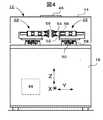
図1は、この実施形態にかかる検査装置の平面図である。以下の説明では、分り易くするために、図示のように、X軸、Y軸及びZ軸の直交座標軸を仮想的に定義する。 FIG. 1 is a plan view of the inspection apparatus according to this embodiment. In the following description, for easy understanding, orthogonal coordinate axes of the X axis, the Y axis, and the Z axis are virtually defined as illustrated.
図1に示すように、この検査装置10は、主装置12と、主装置12に接続された制御装置14とを有する。主装置12は、ワークとしてのクランクシャフト16をその回転軸がX軸に平行に配置して、これをその回転軸回りに回転させつつ、クランクシャフト16のジャーナル部やピン部の外周面のY軸方向の位置(例えば回転軸を原点とした位置であり、以下、表面位置という)を回転角ごとに自動的に測定し、そして、回転角ごとの表面位置データを出力する機械である。制御装置14は、パーソナルコンピュータ、入出力ボード、通信インターフェースボード、シーケンサおよびその他の制御機器(これらの図示は省略)から構成されており、パーソナルコンピュータに組込まれたソフトウェアにより、主装置12の動作を制御すると共に、主装置12から上記表面位置データを読込み、記録し、そして解析することにより、クランクシャフト16のジャーナル部やピン部の外周面の傷の有無を自動的に判定し、その判定結果を出力する。
図1に示すように、主装置12は基台18を有し、この基台18上の中央位置に、X軸と平行にワーク操作ユニット20が設置されている。また、ワーク操作ユニット20の両脇に、複数(例えば4基)の輪郭測定ユニット22、22、22、22が設置されている。このうち、2基の輪郭測定ユニット22、22は、ワーク操作ユニット20の片側に配置され、他の2基のワーク操作ユニット20の反対側に配置されている。これら4基の輪郭測定ユニット22、22、22、22は、図示のように互いに線対称の位置関係をもっているが、その構造は同一である。As shown in FIG. 1, the
As shown in FIG. 1, the
ワーク操作ユニット20は、クランクシャフト16の回転軸がX軸と平行になるようにクランクシャフト16を両端にて支持し、クランクシャフト16をその回転軸回りに一定速度で回転させ、そして、回転角に応じたエンコーダパルスを出力する。このエンコーダパルスに基づいて、上記回転角が算出されることになる。輪郭測定ユニット22、22、22、22の各々は、ワーク操作ユニット20上の回転しているクランクシャフト16の検査対象のジャーナル部又はピン部の外表面のY軸方向の位置に応じたエンコーダパルスを出力する。このエンコーダパルスに基づいて、検査対象のジャーナル部又はピン部の表面位置(外表面のY軸方向の位置)が算出されることになる。 The
基台18内には、図示は省略されているが、ワーク操作ユニット20及び輪郭測定ユニット22、22、22、22のための電源回路、制御装置14からの制御指令に従ってワーク操作ユニット20及び輪郭測定ユニット22、22、22、22を駆動するドライバ回路、並びに、ワーク操作ユニット20及び輪郭測定ユニット22、22、22、22からのエンコーダパルスを入力して、回転角ごとの表面位置を算出し制御装置14へ送信するデータ処理回路(図2、参照番号48)などが収容されている。 Although not shown in the
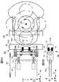
図2は、この検査装置10の正面図であり、ここでは、基台18上の輪郭測定ユニット22、22、22、22の図示を省くことで、ワーク操作ユニット20を判りやすく示してある。図3は、図1のA-A線に沿って見た、ワーク操作ユニット20の片側に位置する2基の輪郭測定ユニット22、22の正面図である。図4は、図1のB-B線に沿って見た、ワーク操作ユニット20の両側に位置する2基の輪郭測定ユニット22、22の断面側面図である。 FIG. 2 is a front view of the
以下、図1から図4を参照して、ワーク操作ユニット20装置及び輪郭測定ユニット22、22、22、22について、より詳細に説明する。 Hereinafter, the
図1及び図2に示されているように、ワーク操作ユニット20は、主軸ユニット24とテールストック26を有する。テールストック26は、その位置をX軸方向に可変するためのテールストックスライド28を有する。テールストックスライド28により、主軸ユニット24からテールストック26までの距離が、クランクシャフト16の長さに応じて適切に設定できる。 As shown in FIGS. 1 and 2, the
主軸ユニット24は、クランクシャフト16の一端を把持するためのチャック30を有する。チャック30は、エア圧駆動のチャッククランプシリンダ32の作用により開閉動することができる。チャック30中心には、チャックセンタ42が設けられる。テールストック26は、クランクシャフト16の他端を支持するためのテールストックセンタ34を有する。テールストックセンタ34は、エア圧駆動のテールストックシリンダ36の作用により前進および後退することができる。テールストックセンタ34はテールストックシリンダ36にバネ(図示せず)を介して結合されており、このバネの作用により、クランクシャフト16を曲げることが無いような一定の力でワークをクランクシャフト16をチャック30に向かって押すことができる。なお、図中、参照番号44は、塵などの侵入を防ぐカバーを示し、参照番号46は、カバー44のワーク搬入搬出口に設けられた自動ドアである。 The
クランクシャフト16がチャック30とテールストックセンタ34との間に配置された仮受け(図示せず)に搬入されると、テールストックセンタ34が前進して、チャックセンタ42と協同して、クランクシャフト16の芯出しを行う。そして、チャック30が閉じてクランクシャフト16の一端を把持する。テールストックセンタ34がクランクシャフト16の他端を支持する。その後、主軸ユニット24に搭載されたステッピングまたはサーボモータよりなる主軸回転モータ38が起動して、チャック30を一定速度で回転させる。それにより、クランクシャフト16がその回転軸回りに一定速度で回転する。主軸ユニット24に搭載された精密ロータリーエンコーダ40が、高精細な回転角ステップで(例えば0.01度ステップで)をエンコーダパルスを出力し、基台10内のデータ処理回路48が、そのエンコーダパルスを入力し計数することで、クランクシャフト16の回転角を高精度に検出する。 When the
図1、図3及び図4に示されているように、各輪郭測定ユニット22は、テーブルスライド50、測定子テーブル52、測定子スライド54及び測定子56を有する。テーブルスライド50は、スライドベース58上に枢着されたボールねじ機構であり、ステッピングモータ又はサーボモータによりなるテーブル移動モータ60により駆動される。テーブルスライド50に測定子テーブル52が搭載される。テーブルスライド50の作用により、測定子テーブル52は、X軸方向に一定の範囲で移動可能である。測定子テーブル52のX軸方向の位置は、クランクシャフト16の検査対象のジャーナル部又はピン部の位置に応じて可変設定される。テーブル移動モータ60に内蔵のエンコーダ又は別置のエンコーダからのパルスに基づいて、測定子テーブル52の位置が検出される。4基の輪郭測定ユニット22、22、22、22のX軸方向位置はそれぞれ独立に設定される。 As shown in FIGS. 1, 3, and 4, each
測定子テーブル52上に、測定子スライド54が設置され、測定子スライド54の先端に測定子56が取り付けられる。測定子スライド54は、ステッピングモータ又はサーボモータである測定子移動モータ66によって駆動されて、測定子56を、Y軸方向に前進及び後退させることができる。測定子56を前進させることにより、測定子56がクランクシャフト16の検査対象のジャーナル部又はピン部の外周に当接する。測定子56がクランクシャフト16に接触する直前のアプローチ速度は、クランクシャフト16を傷つけることのない様な低速度に制御される。測定子56がクランクシャフト16に当接している状態では、測定子スライド54は、これに紐64で結合された錘62により、前進方向(クランクシャフト16を押す方向)へ、測定子56とクランクシャフト16との当接状態を保つための必要最小限の力で加圧される。そのため、クランクシャフト16が回転している間、測定子56はクランクシャフト16の外径形状に忠実に従ってY方向に前進後退しつつ、クランクシャフト16との当接状態を保持する。また、測定子56がクランクシャフト16を曲げたり、傷付けたりすることも防止される。 A
測定子スライド54に連結された精密リニアエンコーダ68(図4)が、測定子56のY軸方向の変位に応じて、高精細な変位ステップでエンコーダパルスを出力する。基台10内のデータ処理回路48が、そのエンコーダパルスを入力し計数することで、測定子56のY軸方向の位置、すなわち、検査対象のジャーナル部又はピン部の表面位置(その外表面のY軸方向の位置)を高精度に算出する。算出された表面位置データは、これと同時に検出された回転角データと共に、データ処理回路48に記録され、そして、制御装置14へ送信される。 A precision linear encoder 68 (FIG. 4) connected to the
4基の輪郭測定ユニット22、22、22、22が、独立して、クランクシャフト16の異なる4つのジャーナル部又はピン部の表面位置を同時に測定する。例えば、図1に例示した場合では、2つのジャーナル部J2及びJ4、並びに2つのピン部P1及びP3の測定が独立して同時に行われる。 The four
図5は、クランクシャフト16の或る検査箇所(ピン部又はジャーナル部)16Aに当接している状態の測定子56の平面図である(ここでは、ピン部との当接状態を例示する)。図6Aは、同状態の測定子56の側面断面図であり、図6Bは、図6AのC−C線での測定子56の平面断面図である。図7は、図5及び図6Aに示した状態からクランクシャフト16がさらに90度回転した状態での測定子56の側面図である。 FIG. 5 is a plan view of the measuring
図5から図7に示すように、測定子56は、測定子スライド54の先端に固定されたヘッド保持体70と、ヘッド保持体70に設けられた軸受に回転自在に取り付けられたスウィングアーム72と、スウィングアーム72bの先端に固定されたヘッド74とを有する。 As shown in FIGS. 5 to 7, the
既に説明した測定子スライド54の作用により、測定子56はY軸方向(図5の矢印84方向)に進退可能であり、クランクシャフト16の検査箇所(ピン部又はジャーナル部)16Aを押す方向に加圧されている。測定子56のヘッド74は、その前端に、クランクシャフト16の検査箇所(ピン部又はジャーナル部)16Aの外表面に当接する当接面74Sを有する。ヘッド74の当接面74Sは、検査箇所16Aの外表面と同等以上の高精度で加工された平面であり、Z軸に平行である。図6及び図7から分るように、ヘッド74の当接面74Sは、クランクシャフト16が回転するときの検出箇所(特にピン部)16AのZ軸方向のストローク長以上の長さをZ軸方向に有する。そのため、ヘッド74の当接面74Sは、クランクシャフト16が回転している間、常時、検出箇所16Aに当接している。また、図5に示すように、ヘッド74の当接面74Sは、上記検査箇所の外表面のX軸方向の直線部分の寸法(幅)にほぼ相当する(厳密には、僅かなクリアランス分だけ小さい)X軸方向の寸法(幅)Wを有しており、よって、クランクシャフト16が1回転すると、検査箇所16Aの外表面の全域に接触することになる。これにより、クランクシャフト16の1回転で、上記検査箇所の外表面の何処に存在する凸傷も見逃すことなく検出できる。 By the action of the
変形例として、ヘッド74の当接面74Sは、検査箇所16AのX軸方向の直線部分に相当する幅のうちの最少幅にほぼ相当する幅を有するようにしてもよい。そして、クランクシャフト16が一回転する都度、測定子56を回転軸方向にその当接面の幅以下の距離だけX軸方向に移動することにより、一つの小さい幅のヘッド74で多種類の幅の検査箇所の傷検出を行えるにようにしてもよい。 As a modified example, the
測定子56のスウィングアーム72は、図5の矢印80で示すように、Z軸方向の回転軸72Cを中心とした一定角度範囲でスウィング可能であり、それにより、ヘッド74を同範囲でスウィング可能とする。このスウィング機能により、クランクシャフト16の曲り誤差や、検査箇所16Aの外表面の回転軸に対する平行度誤差に関わりなく、ヘッド74の当接面74Sは、検査箇所16Aの外表面に全幅に渡って常に当接する。これにより、高精度な傷検出が可能になる。 As shown by an
さらに、測定子56のヘッド74は、ヘッド保持体70の前端に取り付けられた複数(例えば4個)のバネ76により前方へ弾性的に押されており、それにより、外力を受けない自然な状態ではヘッド74は真っ直ぐY軸方向に向いた(つまり、当接面74SがX軸と平行になった)姿勢に保持され、余計な首振りはしない。そのため、ヘッド74が検査箇所16Aにアプローチする際、検査箇所16Aの幅方向両側のチーク部とヘッド74との間のクリアランスが僅かであっても、ヘッド74は、チーク部に接触することなく、検査箇所16Aに到達することができる。 Further, the
以上の構成を有する検査装置10の動作は次のとおりである(主に図1と図2を参照)。 The operation of the
(1) 主装置12上部の自動ドア46が開かれ、例えばオートローダにより、ワークたるクランクシャフト16が、ワーク操作ユニット20のチャック30とテールストック26との間のワーク仮受け(図示せず)上に載せられ、そして、自動ドア46が閉じられる。 (1) The
(2) テールストックセンタ34がクイルシリンダ36の作用で前進し、チャックセンタ42と協働して、クランクシャフト16の芯出を行う。そして、チャック30がクランクシャフト16をしっかり把持する。 (2) The
(3) 上記したチャック30の把持動作と同時に、輪郭測定ユニット22、22、22、22のX軸方向位置が、テーブルスライド50により、測定子56がクランクシャフト16の4つの検査箇所(図1の例では、ピン部P1とP3、及びジャーナル部J1とJ4)の各々のX軸方向位置に位置するように調節される。 (3) At the same time as the gripping operation of the
(4) その後、輪郭測定ユニット22、22、22、22の各々の測定子56が前進し、各検査箇所(ピン部又はジャーナル部)の外表面に当接する。
(5) 全ての測定子56、56、56、56が全ての検査箇所にそれぞれ当接した状態で、クランクシャフト16が回転し、そして、データ処理回路48が、ロータリエンコーダ40とリニアエンコーダ68(図4)からのエンコーダパルスを受けて、例えば0.01度の精度で回転角と、回転角ごとの各測定子56の位置(角検査箇所の表面位置)とを計算する。計算された回転角データと表面位置データは、制御装置14に送信され記録される。
(6) クランクシャフト16の一回転が完了後、全ての測定子56、56、56、56が後退する。続いて、上記(3)から(5)と同様の手順で、4つの輪郭測定ユニット22、22,22,22を用いて、クランクシャフト16の別の4つの検査箇所(例えば、ピン部P2とP4、及びジャーナル部,J2とJ5)の回転角毎の表面位置が測定される。続いて、同様の手順で、2つの輪郭測定ユニット22、22を用いて、残り2つの検査箇所(例えば、ピン部J3とフランジ部FG)の表面位置が測定される。図1、2に例示した4気筒エンジン用のクランクシャフト16の場合、以上の3回転で全ての検査箇所P1〜P4、J1〜J5およびFGの表面位置測定が完了する。因みに、このように3回転で検査が完了する場合、30秒程度のラインサイクルタイムにも対応可能である。(4) Thereafter, each of the measuring
(5) The
(6) After one rotation of the
(7) 制御装置14が、記録された各検出箇所の回転角毎の表面位置データを解析して、各検出箇所の外表面における傷の有無を判定し、判定結果を出力する。 (7) The
以下では、上記(7)に示したデータ解析及び判定を行うための制御装置14の機能と動作について、詳細に説明する。 Hereinafter, functions and operations of the
傷の付いた検査箇所の測定された表面位置データには、検出目的である傷データ以外に、以下の要因による誤差が含まれると考えられる。 It is considered that the measured surface position data of the inspection location with a flaw includes errors due to the following factors in addition to the flaw data that is a detection purpose.
(1) 加工機の加工誤差による形状誤差、
(2) 測定子56のヘッド74の当接面74Sの平面度の誤差、
(3) 測定子56のヘッド74の当接面74SのX軸方向及びZ軸方向の真直度の誤差、
(3) 検査箇所の外表面の平坦度及びX軸方向の真直度の誤差、及び
(4) 検査箇所の回転軸心からの偏心による誤差。(1) Shape error due to processing error of processing machine,
(2) error in flatness of the
(3) Straightness error in the X-axis direction and Z-axis direction of the
(3) The flatness of the outer surface of the inspection location and the straightness error in the X-axis direction, and
(4) Error due to eccentricity from the rotational axis of the inspection location.
回転角に対する表面位置データの変化を表す波形を考えた場合、上記の誤差(1)から(4)の誤差はいずれも、一般的に、その波形に含まれる低周波の波形成分になると考えられる。このことに着眼して、制御装置14は、上記波形の中から、上記誤差と考えられる低周波の波形成分を除去することにより、検査目的とする傷データを実施的に表していると考えられる高周波の波形成分を抽出する。そして、制御装置14は、抽出した高周波成分の波形の勾配又は振幅などに基づいて、傷の有無を判断する。 When considering a waveform representing changes in surface position data with respect to the rotation angle, the errors (1) to (4) above are generally considered to be low-frequency waveform components included in the waveform. . Focusing on this, it is considered that the
上述した低周波成分を除去する手法として、制御装置14は、以下の2種類の手法(1)及び(2)いずれかを採用する。 As a method for removing the low-frequency component described above, the
(A) 測定された回転角ごとの表面位置データから得られる上述した誤差(1)から(4)を含んだ表面位置波形データ(以下、元データという)から、平均化フィルタリングにより高周波成分を除去して低周波波形データを抽出する。そして、元データから、その平均化フィルタリングで抽出された低周波波形データを差し引くことにより、高周波波形データを抽出する。 (A) A high frequency component is removed by averaging filtering from the surface position waveform data (hereinafter referred to as original data) including the errors (1) to (4) described above obtained from the surface position data for each measured rotation angle. Then, low frequency waveform data is extracted. Then, the high-frequency waveform data is extracted by subtracting the low-frequency waveform data extracted by the averaging filtering from the original data.
(B) 元データをフーリエ級数に展開し、そのフーリエ級数から低次の成分だけを抽出して低周波波形データを得る。そして、元データからその低周波波形データを差し引くことにより高周波波形データを抽出する。 (B) The original data is expanded into a Fourier series, and only low-order components are extracted from the Fourier series to obtain low-frequency waveform data. Then, the high frequency waveform data is extracted by subtracting the low frequency waveform data from the original data.
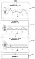
図8は、上記(A)の平均化フィルタリングを用いたデータ処理の手順を示すフローチャートである。 FIG. 8 is a flowchart showing a data processing procedure using the above-described averaging filtering (A).
図8のステップS100で、制御装置14は、測定された1回転分の回転角毎の表面位置データを、回転角の順序で配列することにより、ステップS100にブロック内に図示したような、回転角に対する表面位置の変化波形を示した元データを作成する。このとき、データ処理の負担を軽減するために、測定された例えば0.01度ステップの回転角度ごとの表面位置データを、1度の角度範囲ごとに平均化して、1度ステップの回転角度ごとの表面位置データに変換して、これを元データとして用いてもよい。 In step S100 of FIG. 8, the
ステップS102で、元データを、或る一定の回転角度範囲、例えば30度の範囲、で平均化する。すなわち、元データが上述したような例えば1度ステップの回転角度ごとの表面位置データの配列から成っている場合、1度ステップの各回転角度ごとに、その回転角度を中心とした左右15度の合計30度の回転角度範囲の表面位置データ(31個の表面位置データ)を元データから読み出し、それら31個の表面位置データの平均値データを計算し、そして、その平均値データをその回転角度の表面位置データに置き換える。この30度範囲の平均値データへの置き換えを、0度から359度までの全回転角度の表面位置データに対して行う。これにより、ステップS102のブロック内に示すような、30度範囲で平均化された平均値化データが得られる。この平均値化データは、30度以上の大きい角度範囲での表面位置の変化成分である低周波成分だけを含んだ低周波波形データである。この平均値化データは、上述した誤差(1)から(4)の成分を含んでいるが、傷による表面位置の細かい(つまり高周波の)変化成分は含んでいないと考えられる。因みに、発明者らの実験によれば、平均値化の回転角度範囲として、上に例示した30度という値は、上述した誤差(1)から(4)の成分を除去するために好適な値である。 In step S102, the original data is averaged in a certain rotation angle range, for example, a range of 30 degrees. That is, for example, when the original data is composed of an array of surface position data for each rotation angle of 1 degree step as described above, for each rotation angle of 1 degree step, 15 degrees left and right with the rotation angle as the center. The surface position data (31 surface position data) in a rotation angle range of 30 degrees in total is read from the original data, the average value data of the 31 surface position data is calculated, and the average value data is calculated as the rotation angle. Replace with the surface position data. The replacement with the average value data in the 30 degree range is performed on the surface position data of all rotation angles from 0 degree to 359 degrees. Thereby, averaged data averaged in the range of 30 degrees as shown in the block of step S102 is obtained. This averaged data is low-frequency waveform data including only a low-frequency component that is a change component of the surface position in a large angle range of 30 degrees or more. This averaged data includes the components of the errors (1) to (4) described above, but is considered not to include a fine (that is, high-frequency) change component of the surface position due to scratches. Incidentally, according to the experiments by the inventors, the value of 30 degrees exemplified above as the rotation angle range for averaging is a value suitable for removing the components of the errors (1) to (4) described above. It is.
ステップS104で、元データから平均値化データが差し引かれる。これにより、ステップS104のブロック内に示すような、30度未満の小さい角度範囲内での表面位置の変化成分である高周波成分だけを含んだ高周波波形データが得られる。この高周波波形データに、傷による表面位置の細かい(つまり高周波の)変化成分が含まれている。 In step S104, the averaged data is subtracted from the original data. As a result, high-frequency waveform data including only a high-frequency component that is a change component of the surface position within a small angle range of less than 30 degrees as shown in the block of step S104 is obtained. This high-frequency waveform data includes a fine (that is, high-frequency) change component of the surface position due to scratches.
ステップS106で、高周波波形データの勾配又は振幅などに基づいて、傷の有無が判断される。換言すれば、高周波波形データから急激に変化する部分の変化率(勾配)、変化部分の高さ、幅などが求められ、予め設定された閾値と比較することにより、ピン部又はジャーナル部の凸傷が検出される。例えば、回転角変位1度当りの表面位置の変化量(勾配)の閾値として0.003mmを設定し、この閾値以上の勾配が高周波波形データ中に発見された場合、その部分を傷と判定することができる。或いは、0.1度当たりの変化量(勾配)で判定してもよく、それにより、より高精度な検出が期待される。また、必要に応じて、高周波波形データの山や谷という変化部分の振幅(高さ)又は幅などについて、これを所定の閾値と比較して、その比較結果も判断材料として用いて、傷の有無を判定することもできる。
図9及び図10は、上記(B)のフーリエ展開を用いたデータ処理の手順を示すフローチャートである。In step S106, the presence or absence of a flaw is determined based on the gradient or amplitude of the high-frequency waveform data. In other words, the rate of change (gradient) of the rapidly changing portion, the height and width of the changed portion, etc. are obtained from the high-frequency waveform data, and compared with a preset threshold value, the convexity of the pin portion or journal portion Scratches are detected. For example, if the threshold value of the change amount (gradient) of the surface position per rotation angle displacement is set to 0.003 mm, and a gradient greater than this threshold value is found in the high-frequency waveform data, that portion is determined as a scratch. be able to. Or you may determine by the variation | change_quantity (gradient) per 0.1 degree | times, and, thereby, a highly accurate detection is anticipated. Also, if necessary, the amplitude (height) or width of the changed portion of the high-frequency waveform data, such as peaks and troughs, is compared with a predetermined threshold value, and the comparison result is also used as a judgment material. Presence / absence can also be determined.
9 and 10 are flowcharts showing the procedure of data processing using the Fourier expansion of (B).
図9のステップS200で、既に説明した元データを得る。図9のステップS202から図10のS206で、元データの波形を、
F(t)=a0/2+a1cos(t)+a2cos(2t)+....+ancos(nt)+...+b1sin(t)+b2sin(2t)+...+bnsin(nt)+...
というフーリエ級数の形に展開して、後続のステップS208で低周波波形データを得るために必要な低次の範囲、例えば1次から4次まで、のフーリエ係数a0、a1、a2、a3、a4、b0、b1、b2、b3、b4を求める。そして、これらのフーリエ係数a0、a1、a2、a3、a4、b0、b1、b2、b3、b4から、ステップS202からS206のブロックに示すような、低次範囲の各次成分の波形データが得られる。In step S200 of FIG. 9, the original data already described is obtained. From step S202 in FIG. 9 to S206 in FIG.
F (t) = a 0/ 2 + a 1 cos (t) + a 2 cos (2t) + .... + a n cos (nt) + ... +
The Fourier coefficients a0, a1, a2, etc. in the low-order range necessary for obtaining low-frequency waveform data in the subsequent step S208, for example, from the first to the fourth order, Find a3, a4, b0, b1, b2, b3, b4 . Then, from these Fourier coefficients a0, a1, a2, a3, a4, b0, b1, b2, b3, b4 , and lower order as shown in the blocks of steps S202 to S206 Waveform data of each order component of the range is obtained.
ステップS208で、上述した低次範囲、例えば1次から4次までの波形データを加算した波形データが求められる。この波形データは、元データのうちの4次以下の低周波成分だけを含んだ低周波波形データである。この低周波波形データは、上述した誤差(1)から(4)の成分を含んでいるが、傷による表面位置の細かい(つまり高周波の)変化成分は含んでいないと考えられる。因みに、発明者らの実験によると、求める低周波成分の範囲として、上に例示した4次以下の範囲、又はせいぜい6次以下の範囲が、上記の誤差(1)から(4)の成分を除去する観点から好適である。 In step S208, waveform data obtained by adding the above-described low-order range, for example, waveform data from the first to the fourth order is obtained. This waveform data is low-frequency waveform data including only the fourth-order and lower-order low-frequency components in the original data. This low-frequency waveform data includes the components of the errors (1) to (4) described above, but it is considered that the low-frequency waveform data does not include a fine (that is, high-frequency) change component of the surface position due to scratches. By the way, according to the experiments by the inventors, the range of the low frequency component to be obtained is the range of the 4th order or less exemplified above, or the range of 6th order or less, and the components of the above errors (1) to (4) are It is preferable from the viewpoint of removal.
ステップS210で、元データから低周波波形データが差し引かれる。これにより、ステップS210のブロック内に示すような、5次以上の細かい表面位置の変化成分である高周波成分だけを含んだ高周波波形データが得られる。この高周波波形データに、傷による表面位置の細かい変化成分が含まれている。 In step S210, the low frequency waveform data is subtracted from the original data. As a result, high-frequency waveform data including only a high-frequency component which is a change component of a fine surface position of the fifth or higher order as shown in the block of step S210 is obtained. The high-frequency waveform data includes a fine change component of the surface position due to scratches.
ステップS212で、高周波波形データの勾配又は振幅などに基づいて、傷の有無が判断される。ここでの判断方法は、図8のステップS106でのそれと同様である。 In step S212, the presence or absence of a flaw is determined based on the gradient or amplitude of the high-frequency waveform data. The determination method here is the same as that in step S106 of FIG.
上述した図8又は図9‐図10のデータ処理は、コンピュータによりソフトウェアに従って実行することもできるし、専用のワーヤードハードウェアによって実行することもできるし、或いは、それらの組み合わせによって実行することもできる。 The above-described data processing of FIG. 8 or FIG. 9 to FIG. 10 can be executed according to software by a computer, can be executed by dedicated word hardware, or can be executed by a combination thereof. it can.
以上、本発明の実施形態を説明したが、この実施形態は本発明の説明のための例示にすぎず、本発明の範囲をこの実施形態にのみ限定する趣旨ではない。本発明は、その要旨を逸脱することなく、その他の様々な態様でも実施することができる。 As mentioned above, although embodiment of this invention was described, this embodiment is only the illustration for description of this invention, and is not the meaning which limits the scope of the present invention only to this embodiment. The present invention can be implemented in various other modes without departing from the gist thereof.
10 検査装置
12 主装置
14 制御装置
16 クランクシャフト(ワーク)
16A 検査箇所
20 ワーク操作ユニット
24 主軸ユニット
26 テールストック
22 輪郭測定ユニット
48 データ処理回路
54 測定子スライド
56 測定子
72 スウィングアーム
74 ヘッド
74S 当接面10
Claims (2)
Translated fromJapanese前記ワーク(16)へ向かう方向へ加圧されて、前記ワーク(16)が前記回転軸回りで回転している間、前記ワーク(16)の検査箇所に当接し続け、前記検査箇所に当接する当接面が、前記検査箇所の表面と同等以上の精度で加工された平坦平面であり、かつ、前記検査箇所の回転軸(16C)方向の幅にほぼ相当する前記回転軸(16C)方向の幅(W)である測定子を有し、前記ワークを前記回転軸回りに回転させ、回転角度ごとに前記測定子(56)の位置を計測することにより、前記検査箇所の回転角度ごとの表面位置を測定する表面位置測定手段(20、22、48)と、
前記表面位置測定手段(20、22、48)の出力信号を受けて、前記回転角に対する前記表面位置の波形を表す表面波形データを得る表面波形取得手段(14)と、
前記表面波形データから、所定周波数より高い周波数をもつ又は所定角度より小さい角度範囲内での位置変化を示す高周波波形データを抽出する高周波波形抽出手段(14)と、
抽出された前記高周波波形データに基づいて、前記検査箇所における傷の有無を判定する傷判定手段(14)と、を備えた傷検査装置。In the apparatus (10) for inspecting the surface for scratchesby rotating the work (16)around a predetermined rotation axis ,
While being pressed in the direction toward the work (16) and the work (16) is rotating around the rotation axis, the work (16) is kept in contact with the inspection location and is in contact with the inspection location. The contact surface is a flat plane processed with an accuracy equal to or higher than the surface of the inspection location, and the rotation axis (16C) direction substantially corresponds to the width of the inspection location in the rotation axis (16C) direction. A surface having a measuring element having a width (W), rotating the workpiece around the rotation axis, and measuring the position of the measuring element (56) for each rotation angle, thereby measuring the surface for each rotation angle of the inspection location. Surface position measuring means (20, 22, 48) for measuring the position;
Surface waveform acquisition means (14) for receiving an output signal of the surface position measurement means (20, 22, 48) and obtaining surface waveform data representing a waveform of the surface position with respect to the rotation angle;
High-frequency waveform extraction means (14) for extracting, from the surface waveform data, high-frequency waveform data indicating a position change within an angular range having a frequency higher than a predetermined frequency or smaller than a predetermined angle;
A wound inspection apparatus comprising: wound determination means (14) for determining the presence or absence of a scratch at the inspection location based on the extracted high-frequency waveform data.
前記ワーク(16)へ向かう方向へ加圧されて、前記ワーク(16)が前記回転軸回りで回転している間、前記ワーク(16)の検査箇所に当接し続け、前記検査箇所に当接する当接面が、前記検査箇所の表面と同等以上の精度で加工された平坦平面であり、かつ、前記検査箇所の回転軸(16C)方向の幅にほぼ相当する前記回転軸(16C)方向の幅(W)である測定子の、回転角ごとの位置を計測するステップと、
計測された前記測定子の回転角度ごとの位置から、前記検査箇所の回転角度ごとの表面位置を計測するステップと、
測定された前記回転角ごとの表面位置から、前記回転角に対する前記表面位置の波形を表す表面波形データを得るステップ(S100、S200)と、
前記表面波形データから、所定周波数より高い周波数をもつ又は所定角度より小さい角度範囲内での位置変化を示す高周波波形データを抽出するステップ(S102-S104、S202-S210)と、
抽出された前記高周波波形データに基づき、前記検査箇所の表面の傷の有無を判定するステップ(S106、S212)と
を備えた傷検査方法。
In the method of inspecting the surface for scratchesby rotating the workpiece (16)about a predetermined rotation axis ,
While being pressed in the direction toward the work (16) and the work (16) is rotating around the rotation axis, the work (16) is kept in contact with the inspection location and is in contact with the inspection location. The contact surface is a flat plane processed with an accuracy equal to or higher than the surface of the inspection location, and the rotation axis (16C) direction substantially corresponds to the width of the inspection location in the rotation axis (16C) direction. A step of measuring the position of each measuring angle of a measuring element having a width (W);
Measuring the surface position for each rotation angle of the inspection location from the measured position for each rotation angle of the probe;
Obtaining surface waveform data representing a waveform of the surface position relative to the rotation angle from the measured surface position for each rotation angle (S100, S200);
Extracting from the surface waveform data high-frequency waveform data indicating a position change within an angular range having a frequency higher than a predetermined frequency or smaller than a predetermined angle (S102-S104, S202-S210);
And a step (S106, S212) of determining whether or not there is a scratch on the surface of the inspection location based on the extracted high-frequency waveform data.
Priority Applications (4)
| Application Number | Priority Date | Filing Date | Title |
|---|---|---|---|
| JP2004256776AJP4596863B2 (en) | 2004-09-03 | 2004-09-03 | Inspection device and method for scratches on workpiece surface |
| DE112005002030TDE112005002030T5 (en) | 2004-09-03 | 2005-08-25 | Apparatus and method for checking for defects on the surface of workpieces |
| US11/659,737US7499813B2 (en) | 2004-09-03 | 2005-08-25 | Device and method for inspecting for flaw on surface of work |
| PCT/JP2005/015461WO2006025257A1 (en) | 2004-09-03 | 2005-08-25 | Device and method for inspecting for flaw on surface of work |
Applications Claiming Priority (1)
| Application Number | Priority Date | Filing Date | Title |
|---|---|---|---|
| JP2004256776AJP4596863B2 (en) | 2004-09-03 | 2004-09-03 | Inspection device and method for scratches on workpiece surface |
Publications (2)
| Publication Number | Publication Date |
|---|---|
| JP2006071529A JP2006071529A (en) | 2006-03-16 |
| JP4596863B2true JP4596863B2 (en) | 2010-12-15 |
Family
ID=35999914
Family Applications (1)
| Application Number | Title | Priority Date | Filing Date |
|---|---|---|---|
| JP2004256776AExpired - Fee RelatedJP4596863B2 (en) | 2004-09-03 | 2004-09-03 | Inspection device and method for scratches on workpiece surface |
Country Status (4)
| Country | Link |
|---|---|
| US (1) | US7499813B2 (en) |
| JP (1) | JP4596863B2 (en) |
| DE (1) | DE112005002030T5 (en) |
| WO (1) | WO2006025257A1 (en) |
Families Citing this family (15)
| Publication number | Priority date | Publication date | Assignee | Title |
|---|---|---|---|---|
| US7607824B2 (en)* | 2006-10-25 | 2009-10-27 | Delphi Technologies, Inc. | Method of analyzing electrical connection and test system |
| JP5107590B2 (en)* | 2007-02-26 | 2012-12-26 | 住友金属テクノロジー株式会社 | Railway wheel dimension measuring device |
| IT1396169B1 (en)* | 2009-10-13 | 2012-11-16 | T&T S P A | METHOD AND EQUIPMENT FOR THE DISCRIMINATION OF SCREWS WITHOUT NOISE. |
| CN102597753B (en)* | 2009-11-18 | 2014-12-10 | 本田技研工业株式会社 | Surface inspection device and surface inspection method |
| JP5580223B2 (en)* | 2011-02-18 | 2014-08-27 | 本田技研工業株式会社 | Method for determining surface properties of articles |
| CN103616008B (en)* | 2013-11-28 | 2016-01-20 | 厦门大学 | A kind of surface roughometer probe protection device |
| US20210133871A1 (en) | 2014-05-20 | 2021-05-06 | State Farm Mutual Automobile Insurance Company | Autonomous vehicle operation feature usage recommendations |
| US20150226639A1 (en)* | 2015-04-27 | 2015-08-13 | Caterpillar Inc. | Method of inspecting worn surfaces of camshaft lobes |
| US10134278B1 (en) | 2016-01-22 | 2018-11-20 | State Farm Mutual Automobile Insurance Company | Autonomous vehicle application |
| US10493936B1 (en) | 2016-01-22 | 2019-12-03 | State Farm Mutual Automobile Insurance Company | Detecting and responding to autonomous vehicle collisions |
| JP7260735B2 (en)* | 2018-10-03 | 2023-04-19 | 日本製鉄株式会社 | Crack initiation evaluation device and crack initiation evaluation method |
| DE102020101363A1 (en)* | 2020-01-21 | 2021-07-22 | Infineon Technologies Ag | Sensor, control unit and method for determining the direction of a magnetic field |
| CN114942124A (en)* | 2020-05-27 | 2022-08-26 | 广东原点智能技术有限公司 | Automobile crankshaft appearance quality inspection platform |
| WO2022195760A1 (en)* | 2021-03-17 | 2022-09-22 | 株式会社Fuji | Inspection device |
| CN115356008B (en)* | 2022-09-20 | 2023-04-04 | 深圳市东河仪表有限公司 | Temperature sensor |
Family Cites Families (19)
| Publication number | Priority date | Publication date | Assignee | Title |
|---|---|---|---|---|
| JPS5951875B2 (en)* | 1980-05-28 | 1984-12-17 | 東洋製罐株式会社 | Automatic discrimination and removal method and device for defective empty cans |
| DE3306194A1 (en)* | 1982-02-25 | 1983-09-08 | Mitsubishi Denki K.K., Tokyo | METHOD FOR TESTING SCREW SURFACES FOR FAULTS AND DEVICE FOR IMPLEMENTING THEM |
| JPS63243751A (en)* | 1987-03-31 | 1988-10-11 | Ngk Insulators Ltd | Method, jig and apparatus for ultrasonic flaw detection of rotary body for bearing |
| JPH0755494Y2 (en)* | 1989-10-23 | 1995-12-20 | 富士重工業株式会社 | Crank pin flaw detector |
| IT1253305B (en)* | 1991-11-12 | 1995-07-14 | Marposs Spa | APPARATUS AND METHOD FOR CHECKING THE CHARACTERISTICS OF A CAMSHAFT |
| US5532591A (en)* | 1992-02-27 | 1996-07-02 | Logue; Delmar L. | Apparatus for detecting surface flaws in cylindrical articles by means of asymmetric magnetic detection |
| JPH06265334A (en)* | 1993-01-18 | 1994-09-20 | Nissan Motor Co Ltd | Crankshaft inspection device and method |
| KR100245805B1 (en)* | 1995-03-10 | 2000-04-01 | 가나이 쓰도무 | Inspection method and apparatus and manufacturing method of semiconductor device using the same |
| JPH10177326A (en)* | 1996-12-18 | 1998-06-30 | Fuji Xerox Co Ltd | Method for judging abnormality of rotating and carrying member and abnormality judging device |
| DE69806833T2 (en)* | 1997-04-04 | 2003-04-10 | Toyota Jidosha K.K., Toyota | Three-dimensional cam and valve train device |
| JP3405169B2 (en)* | 1998-01-21 | 2003-05-12 | トヨタ自動車株式会社 | 3D cam profile pass / fail determination method, 3D cam profile measurement, 3D cam profile measurement method, and 3D cam profile measurement device |
| JP3807829B2 (en) | 1997-09-03 | 2006-08-09 | コマツ工機株式会社 | Crankshaft automatic measuring device and measuring method thereof |
| JPH11271008A (en)* | 1998-03-25 | 1999-10-05 | Ricoh Co Ltd | Cylindrical inspection object inspection equipment |
| JP2000234924A (en)* | 1999-02-17 | 2000-08-29 | Ricoh Co Ltd | Sheet inspection system |
| JP2000241154A (en)* | 1999-02-17 | 2000-09-08 | Ricoh Co Ltd | Rotary body defect detection device |
| TW490559B (en)* | 1999-07-30 | 2002-06-11 | Hitachi Construction Machinery | Ultrasonic inspection apparatus and ultrasonic detector |
| JP2001255105A (en)* | 2000-03-13 | 2001-09-21 | Ngk Insulators Ltd | Defect inspection method for axially symmetric object |
| JPWO2002057656A1 (en)* | 2001-01-17 | 2004-05-20 | 日本精工株式会社 | Sliding rotating body for toroidal type continuously variable transmission and evaluation method thereof |
| JP3932400B2 (en)* | 2002-08-05 | 2007-06-20 | カヤバ工業株式会社 | Surface defect detection system and data processing method |
- 2004
- 2004-09-03JPJP2004256776Apatent/JP4596863B2/ennot_activeExpired - Fee Related
- 2005
- 2005-08-25USUS11/659,737patent/US7499813B2/ennot_activeExpired - Fee Related
- 2005-08-25WOPCT/JP2005/015461patent/WO2006025257A1/enactiveApplication Filing
- 2005-08-25DEDE112005002030Tpatent/DE112005002030T5/ennot_activeWithdrawn
Also Published As
| Publication number | Publication date |
|---|---|
| US7499813B2 (en) | 2009-03-03 |
| WO2006025257A1 (en) | 2006-03-09 |
| DE112005002030T5 (en) | 2007-10-18 |
| JP2006071529A (en) | 2006-03-16 |
| US20080033664A1 (en) | 2008-02-07 |
Similar Documents
| Publication | Publication Date | Title |
|---|---|---|
| JP4596863B2 (en) | Inspection device and method for scratches on workpiece surface | |
| JP7374271B2 (en) | Measurement of toothed articles using multiple sensors | |
| US7278222B2 (en) | Method for measuring a program-controlled machine tool | |
| JPS62264856A (en) | Cylinder grinder | |
| CN109060966B (en) | An ultrasonic transducer automatic calibration device | |
| JP3807829B2 (en) | Crankshaft automatic measuring device and measuring method thereof | |
| US5551906A (en) | Caliper assembly for grinder | |
| JP3943032B2 (en) | Equipment for inspecting the diameter of the eccentric part of a machine part during machining with a grinding machine | |
| CN114072252A (en) | Method and apparatus for controlling a workpiece during its manufacture | |
| JP3845602B2 (en) | Measuring device and measuring method of rotational phase angle at eccentric part of shaft, and spline groove phase measuring jig used for the measurement | |
| JPH0425302A (en) | Cutting method for forming or reforming railway vehicle wheel | |
| US5678964A (en) | Method of determining slide straightness and for providing a straight reference surface for a machine tool | |
| KR20190005570A (en) | Continuous processing method and its system | |
| CN113840688A (en) | Positional relationship measuring method, contact detecting method, and machining apparatus | |
| CN111408549A (en) | A device and method for testing copper foil welding effect | |
| JP3660920B2 (en) | Machine tool and processing method | |
| CN111678483B (en) | A Servo Motor Driven Inner Diameter Measuring Device | |
| JP3716895B2 (en) | R groove measuring probe and crankshaft R groove measuring device | |
| JPH0377443B2 (en) | ||
| JP3851046B2 (en) | Straightness correction method for measuring machine and measuring machine | |
| JPH0318711A (en) | Instrument and method for tool inspection | |
| CN112025409B (en) | Method for detecting contour precision in numerical control machining of stamping die | |
| CN218329695U (en) | Device for detecting outer diameter of transmission shaft during automatic turning production | |
| RU2198378C2 (en) | Multipurpose spherometer | |
| JPH0653913U (en) | Automatic roundness inspection device |
Legal Events
| Date | Code | Title | Description |
|---|---|---|---|
| A625 | Written request for application examination (by other person) | Free format text:JAPANESE INTERMEDIATE CODE: A625 Effective date:20070511 | |
| A131 | Notification of reasons for refusal | Free format text:JAPANESE INTERMEDIATE CODE: A131 Effective date:20100420 | |
| A521 | Request for written amendment filed | Free format text:JAPANESE INTERMEDIATE CODE: A523 Effective date:20100621 | |
| A131 | Notification of reasons for refusal | Free format text:JAPANESE INTERMEDIATE CODE: A131 Effective date:20100713 | |
| A521 | Request for written amendment filed | Free format text:JAPANESE INTERMEDIATE CODE: A523 Effective date:20100825 | |
| TRDD | Decision of grant or rejection written | ||
| A01 | Written decision to grant a patent or to grant a registration (utility model) | Free format text:JAPANESE INTERMEDIATE CODE: A01 Effective date:20100914 | |
| A01 | Written decision to grant a patent or to grant a registration (utility model) | Free format text:JAPANESE INTERMEDIATE CODE: A01 | |
| A61 | First payment of annual fees (during grant procedure) | Free format text:JAPANESE INTERMEDIATE CODE: A61 Effective date:20100921 | |
| R150 | Certificate of patent or registration of utility model | Free format text:JAPANESE INTERMEDIATE CODE: R150 | |
| FPAY | Renewal fee payment (event date is renewal date of database) | Free format text:PAYMENT UNTIL: 20131001 Year of fee payment:3 | |
| FPAY | Renewal fee payment (event date is renewal date of database) | Free format text:PAYMENT UNTIL: 20131001 Year of fee payment:3 | |
| S111 | Request for change of ownership or part of ownership | Free format text:JAPANESE INTERMEDIATE CODE: R313111 | |
| FPAY | Renewal fee payment (event date is renewal date of database) | Free format text:PAYMENT UNTIL: 20131001 Year of fee payment:3 | |
| R350 | Written notification of registration of transfer | Free format text:JAPANESE INTERMEDIATE CODE: R350 | |
| LAPS | Cancellation because of no payment of annual fees |