JP4596239B2 - Light source light amount adjustment method, light source light amount adjustment program and light source light amount adjustment system for scanner - Google Patents
Light source light amount adjustment method, light source light amount adjustment program and light source light amount adjustment system for scannerDownload PDFInfo
- Publication number
- JP4596239B2 JP4596239B2JP2004191533AJP2004191533AJP4596239B2JP 4596239 B2JP4596239 B2JP 4596239B2JP 2004191533 AJP2004191533 AJP 2004191533AJP 2004191533 AJP2004191533 AJP 2004191533AJP 4596239 B2JP4596239 B2JP 4596239B2
- Authority
- JP
- Japan
- Prior art keywords
- light
- light source
- value
- photoelectric conversion
- amount
- Prior art date
- Legal status (The legal status is an assumption and is not a legal conclusion. Google has not performed a legal analysis and makes no representation as to the accuracy of the status listed.)
- Expired - Fee Related
Links
Images


Landscapes
- Facsimile Heads (AREA)
- Facsimile Scanning Arrangements (AREA)
- Light Sources And Details Of Projection-Printing Devices (AREA)
Description
Translated fromJapanese本発明は、少なくとも光の三原色のそれぞれに適応した複数の光源と複数の光電変換センサからなるスキャナのための光源光量調整技術に関する。 The present invention relates to a light source light amount adjustment technique for a scanner including a plurality of light sources adapted to at least three primary colors of light and a plurality of photoelectric conversion sensors.
大量の熱を発生することで発光効率が悪いハロゲンランプに代えて、赤色、緑色、青色の複数のLED(発光ダイオード)を光源として採用したスキャナが登場している。各LEDの発光輝度や発光時間はその制御信号によって制御され、スキャニング対象に対して適切な光量が照射される。このようなLED光源タイプのフィルムスキャナとして、LED光源によってスキャニング対象を面状に照射してその透過光量をイメージエリアセンサで検出して画像データを取得するエリアスキャンスキャナ(例えば、特許文献1参照。)と、LED光源によってスキャニング対象を線状に照射してその主走査方向の透過光量をイメージラインセンサで検出しながらスキャニング対象を副走査方向に移動させることで画像データを取得するリニアスキャンスキャナ(例えば、特許文献2参照。)が存在する。いずれにしても、各色LEDにおける光量のばらつきをなくするため、その制御量(光源駆動電流)を調整することによる光量調整を行う必要があり、例えば上記特許文献1では、特性値算定部が、イメージエリアセンサからの色信号から、各点の三色分解濃度を求め、これをむら修正データ算定部に送り、そこで、まず1フレーム分の濃度の中から抽出された最大濃度と各点の濃度との差をそれぞれ求め、これをむら修正データとして三色の色毎にメモリに書き込んでおき、このむら修正データと各色LEDの発光輝度と発光時間データとによって全てのLEDに対する発光輝度と発光時間を決定し、これをLED制御信号としてLED光源駆動部に送るように構成している。 Scanners that employ a plurality of red, green, and blue LEDs (light emitting diodes) as light sources instead of halogen lamps that generate a large amount of heat and have low luminous efficiency have appeared. The light emission luminance and light emission time of each LED are controlled by the control signal, and an appropriate amount of light is irradiated to the scanning target. As such an LED light source type film scanner, an area scan scanner that obtains image data by irradiating a scanning target with an LED light source in a plane and detecting the amount of transmitted light with an image area sensor (see, for example, Patent Document 1). ) And a linear scan scanner that obtains image data by irradiating the scanning object linearly with an LED light source and moving the scanning object in the sub-scanning direction while detecting the amount of transmitted light in the main scanning direction with the image line sensor ( For example, see
少なくとも光の三原色のそれぞれに適応した複数の光源(代表的にはLED光源)と複数の光電変換センサ(代表的にはCCDセンサ)からなるスキャナにおいて、各光源(代表的にはR、G、Bの3つの光源で各光源は多数のLEDから構成される)の光量を目標値に合わせるために、各色の光源を点灯して全体として白色光を照射した状態(これを全光源点灯状態と呼び全灯状態と略称する)において各色の光電変換センサで取得された各色の読取データが利用されているが、各光源からの光ビームは特定色の波長を中心としてある程度の広がりをもった波長範囲を有することから、つまり各特定色の光電変換センサがそれ以外の色の光源からの光ビームにも幾分か反応して光電変換するため、取得された各色の読取データが各色の光源の光量に一致せず、高精度の光量調整が困難となる。この問題を避けるためには、各色の光源を個別に点灯させた状態(これを単独点灯状態と呼び単灯状態と略称する)で特定色成分毎に個別に光量調整を行う必要があるが、これは光源光量調整作業を増大させ、特に時間的な負担を増大させる。 In a scanner comprising a plurality of light sources (typically LED light sources) and a plurality of photoelectric conversion sensors (typically CCD sensors) adapted to at least the three primary colors of light, each light source (typically R, G, In order to adjust the amount of light of each of the three light sources of B to a target value, the light source of each color is turned on and irradiated with white light as a whole (this is referred to as the all light source lighting state) The reading data of each color acquired by the photoelectric conversion sensor of each color is used in the abbreviated as “all-light condition”, but the light beam from each light source has a wavelength that spreads to a certain extent around the wavelength of the specific color The photoelectric conversion sensor for each specific color reacts somewhat with the light beams from the light sources of the other colors to perform photoelectric conversion, so that the acquired read data for each color is the light source for each color. Does not match the amount of light, it is difficult to light quantity adjustment with high accuracy. In order to avoid this problem, it is necessary to individually adjust the light amount for each specific color component in a state where the light sources of each color are individually lit (referred to as a single lighting state and abbreviated as a single lighting state). This increases the light source light quantity adjustment work, and particularly increases the time burden.
上記実状に鑑み、本発明の課題は、少なくとも光の三原色のそれぞれに適応した複数の光源(代表的にはLED光源)と複数の光電変換センサ(代表的にはCCDセンサ)からなるスキャナにおける日常的な光源光量調整を全灯状態で行いながらも単灯状態での光源光量調整に匹敵する精度で行い得る技術を提供することである。 In view of the above situation, an object of the present invention is to make daily life in a scanner comprising a plurality of light sources (typically LED light sources) and a plurality of photoelectric conversion sensors (typically CCD sensors) adapted to at least the three primary colors of light. It is intended to provide a technique that can be performed with an accuracy comparable to light source light amount adjustment in a single lamp state while performing general light source light amount adjustment in all lamp states.
少なくとも光の三原色のそれぞれに適応した、赤色成分の光ビームを放射するLED素子列からなるR光源と、緑色成分の光ビームを放射するLED素子列からなるG光源と、青色成分の光ビームを放射するLED素子列からなるB光源とからなる光源、及びR光電変換センサと、G光電変換センサと、R光電変換センサとからなる光電変換センサからなるスキャナのための光源光量調整方法において上記課題を達成するため、本発明では、各前記光源の単独点灯時に各前記光電変換センサによって取得された測定光量値に基づいて全前記光源点灯時の測定光量値から各前記光源の光量値を推定する関係式を求めるステップと、各前記光源の目標光量値を設定するステップと、前記目標光量値に適した前記光源に対する制御量を設定するステップと、全前記光源点灯時に各前記光電変換センサによって取得された測定光量値から前記関係式を用いて各前記光源の推定光量値を算定するステップと、前記推定光量値と前記目標光量値との差に応じて各前記光源に対する修正制御量を決定するステップとからなることを特徴としている。AnR light source composed of an LED element array that emits a red component light beam, a G light source composed of an LED element array that emits a green component light beam, and a blue component light beam adapted to each of the three primary colorsof light. The above-mentioned problem in a light source light quantity adjusting method for a scannercomprising a lightsource comprising a B light source comprising a radiating LED element array, and a photoelectric conversion sensor comprising an R photoelectric conversion sensor, a G photoelectric conversion sensor, and an R photoelectric conversion sensor. to achieve, in the present invention, to estimate the light quantity value of eachlight source from the measured light quantity value at fulllight source lights up based on a measured light value obtained byeach of said photoelectric conversion sensors in a single time of lighting of thelight source determining a relational expression, setting a target light amount value of each ofthe light sources, stearyl for setting a control amount for said light source suitable to the target light amount value And flop, a step of calculating the estimated light intensity values of each ofthe light sources by using the relational expression from allthe light source measured light value obtained byeach of said photoelectric conversion sensor when lit, the estimated amount value and the target light amount value It is characterized by comprising the step of determining a correction control amount for eachsaid light source in accordance with the difference.
この方法では、まず、使用するスキャナに対して、各光源を順次単独点灯しながら各光源毎に例えば各光電変換センサによって取得されたそれぞれの測定光量値に基づいて、全ての光源を同時に点灯させた状態で各光電変換センサに取得された測定光量値から、各光源のための他の光源からは独立した光量値を推定する関係式を求めておく。それ以後の日常的な光源光量調整作業においては、この既に求められている関係式を用いて、全光源点灯状態での測定光量値から各光源の他の光源の影響を受けていない推定光量値を算定し、その算定された推定光量値を用いて各光源に対する修正された制御量が決定されるので、短時間で行い得る全灯状態での光源光量調整でありながらも単灯状態での光源光量調整に匹敵する精度が得られる。 In this method, first, with respect to the scanner to be used, all the light sources are turned on simultaneously based on the respective measured light quantity values obtained by, for example, each photoelectric conversion sensor for each light source while sequentially turning on each light source individually. A relational expression for estimating a light amount value independent of other light sources for each light source is obtained from the measured light amount value acquired by each photoelectric conversion sensor in the above state. In the routine light source light quantity adjustment work after that, using this already obtained relational expression, the estimated light quantity value that is not affected by the other light sources of each light source from the measured light quantity value when all the light sources are turned on The corrected control amount for each light source is determined using the calculated estimated light amount value, so that the light source light amount adjustment in a full light state that can be performed in a short time, but in a single light state Accuracy comparable to light source light amount adjustment can be obtained.
全ての光源を同時に点灯させた状態で各光電変換センサに取得された測定光量値から、各光源のための他の光源からは独立した光量値を推定する関係式の具体例の1つとして、各光源からの照射光が同一色成分の光電変換センサによって取得される同色測定光量値と異なる色成分の光電変換センサによって取得される異色測定光量値とから求められる、光源光量から測定光量値への変換行列の逆行列を用いて定義されるものが提案される。例えば、R・G・B毎の光源とR・G・B毎の光電変換センサを備えたスキャナの場合、R光源単独点灯時の各R・G・B光電変換センサによって取得された輝度値(画像データの画素値)をR光電変換センサによる輝度値で正規化する工程を、GとBに対しても行い、その結果得られるR・G・B光源の光量をR・G・B光電変換センサによって取得される光量値(光電変換によって得られた測定光量値)に変換する変換行列(3×3)の逆行列を、R・G・B光電変換センサによって取得される光量値から実際のR・G・B光源の光量を求めるための変換行列とすることができる。従ってこの最終的に得られた変換行列を用いた変換式が上述の関係式となる。なお、このような関係式は、コンピュータ上で扱われる場合、通常予めテーブル化されて用いられることから、本願明細書での関係式なる用語は、数学的な数式及びその関係式の値をテーブル化したもの等を含む広義な用語として用いられている。 As one of the specific examples of the relational expression for estimating the light quantity value independent of other light sources for each light source from the measured light quantity value acquired by each photoelectric conversion sensor with all the light sources turned on simultaneously, From the light source light amount to the measured light amount value obtained from the same color measured light amount value acquired by the photoelectric conversion sensor of the same color component and the different color measured light amount value acquired by the different color component photoelectric conversion sensor. What is defined using the inverse of the transformation matrix is proposed. For example, in the case of a scanner having a light source for each of R, G, and B and a photoelectric conversion sensor for each of R, G, and B, the brightness value (obtained by each R, G, and B photoelectric conversion sensor when the R light source is lit alone ( The process of normalizing the pixel value of the image data) with the luminance value by the R photoelectric conversion sensor is also performed for G and B, and the resulting light quantity of the R, G, B light source is R, G, B photoelectric conversion The inverse matrix of the conversion matrix (3 × 3) for converting the light quantity value acquired by the sensor (measured light quantity value obtained by photoelectric conversion) from the light quantity value acquired by the R, G, B photoelectric conversion sensor It can be set as a conversion matrix for obtaining the light amounts of the R, G, and B light sources. Therefore, the conversion formula using the finally obtained conversion matrix is the above-described relational expression. Note that when such a relational expression is handled on a computer, it is usually used as a table in advance. Therefore, the term relational expression in this specification is a mathematical expression and a value of the relational expression. It is used as a broad term including those that have been made into a variety.
本発明の好適な実施形態の1つでは、前記修正制御量を決定するステップを複数回行うことで得られた修正制御量と推定光量値の関係から前記目標光量値のための最適な修正制御量を決定することが提案される。1回だけの調整工程で、最適な制御量を得る可能性は低いので、複数回、例えば2回の調整工程で得られた2組の修正制御量と推定光量値からそれらの関係を割り出して、その収束方向から目標光量値を得るための最適な制御量を見出すようにするのである。 In a preferred embodiment of the present invention, optimal correction control for the target light amount value is obtained from the relationship between the correction control amount obtained by performing the step of determining the correction control amount a plurality of times and the estimated light amount value. It is proposed to determine the quantity. Since it is unlikely that an optimal control amount will be obtained in a single adjustment step, the relationship between two sets of corrected control amounts and estimated light intensity values obtained in multiple adjustment steps, for example, two adjustment steps, is calculated. The optimum control amount for obtaining the target light amount value is found from the convergence direction.
光電変換センサによって取得される輝度データにはどうしてもノイズ(電気ノイズや光電変換ノイズなど)が含まれるが、そのようなノイズの影響をできるだけ低減するため、本発明の好適な実施形態の1つでは、測定光量値として、光源からの光を光電変換センサが複数ライン分ラインスキャニングして得られた輝度データに対して平均化フィルタをかけた後平均演算して得られた値が用いられる。 The luminance data acquired by the photoelectric conversion sensor necessarily includes noise (electrical noise, photoelectric conversion noise, etc.). In order to reduce the influence of such noise as much as possible, in one of the preferred embodiments of the present invention, As the measured light quantity value, a value obtained by applying an averaging filter to luminance data obtained by scanning the light from the light source for a plurality of lines by the photoelectric conversion sensor is used.
本発明では、上述した画像処理方法をコンピュータに実行させるプログラムやそのプログラムを記録した媒体も権利の対象とするものであり、そのような光源光量調整プログラムは、各前記光源の単独点灯時に各前記光電変換センサによって取得された測定光量値に基づいて求められた、全前記光源点灯時の測定光量値から各前記光源の光量値を推定する関係式を読み込む機能と、各前記光源の目標光量値を設定する機能と、前記目標光量値に適した前記光源に対する制御量を設定する機能と、全前記光源点灯時に各前記光光電変換センサによって取得された測定光量値から前記関係式を用いて各前記光源の推定光量値を算定する機能と、前記推定光量値と前記目標光量値との差に応じて各前記光源に対する修正制御量を決定する機能とをコンピュータに実現させる。当然ながら、このような光源光量調整プログラムも上述した光源光量調整方法で述べたすべての実施態様を採用することができるとともに、上述した全ての作用効果を得ることができる。In the present invention, the medium for recording a program or program for executing the image processing method described above to the computer is also intended to be subjected to right, such a light source light amount adjustment program,each said at single lighting of eachlight source obtained based on the measured light quantity values acquired by the photoelectric conversion sensor, a function to read a relational expression for estimating the light intensity value of each ofthe light sources from the measured light quantity value at fulllight source lighting, the target light quantity of eachlight source a function of setting, each with a function of setting a control amount for said light source suitable to the target light amount value, the relational expression from the measured light value obtained byeach of said light photoelectric conversion sensor when allthe source lighting co a function to calculate the estimated light intensity values ofthe light source, and a function of determining a correction control amount for eachsaid light source in accordance with the difference between the target light quantity and the estimated quantity value To realize the computer. Naturally, such a light source light amount adjustment program can adopt all the embodiments described in the light source light amount adjustment method described above, and can obtain all the above-described effects.
本発明では、さらに、上述した光源光量調整方法を実施する光源光量調整システムも権利の対象としており、そのような光源光量調整システムは、各前記光源の単独点灯時に各前記光電変換センサによって取得された測定光量値に基づいて求められた、全前記光源点灯時の測定光量値から各前記光源の光量値を推定する関係式を読み出し可能に格納する関係式格納部と、各前記光源の目標光量値を設定する目標光量値設定部と、前記目標光量値に適した前記光源に対する制御量を設定する制御量設定部と、全前記光源点灯時に各前記光電変換センサによって取得された測定光量値から前記関係式を用いて各前記光源の推定光量値を算定する推定光量値算定部と、前記推定光量値と前記目標光量値との差に応じて各前記光源に対する修正制御量を決定する制御量決定部とを備えている。当然ながら、このような光源光量調整システムも上述した光源光量調整方法で述べたすべての実施態様を備えるとともに、上述した全ての作用効果を得ることができる。
本発明によるその他の特徴及び利点は、以下図面を用いた実施形態の説明により明らかになるだろう。In the present invention, furthermore, the light source light amount adjustment system for implementing the light source light quantity adjusting method described above are also the subject of rights, such a light source light intensity adjustment system is acquired byeach of said photoelectric conversion sensor when alone lighting of eachlight source It was obtained based on the measured light intensity value, a relational expression storage unit that readably stores a relational expression for estimating the light intensity value of each ofthe light sources from the measured light quantity value at fulllight source lighting, target light of eachlight source a target light amount value setting unit for setting a value, and a control amount setting unit for setting a control amount for said light source suitable to the target light amount value, from allthe light source measured light value obtained byeach of said photoelectric conversion sensor when lit and estimated quantity value calculation unit to calculate the estimated light intensity values of each ofthe light sources by using the relational expression, modified control amounts for thelight source in accordance with the difference between the target light quantity and the estimated quantity value And a control amount determining unit determined. Naturally, such a light source light amount adjustment system also includes all the embodiments described in the light source light amount adjustment method described above, and can obtain all the above-described effects.
Other features and advantages of the present invention will become apparent from the following description of embodiments using the drawings.
図1に、本発明による光源光量調整技術が組み込まれたスキャナシステムの一例が模式的に示されている。このシステムはフィルムスキャナ1として構成されているスキャナとこのフィルムスキャナ1によって取得された読取信号(輝度データ)を処理するコントローラ60から構成されている。 FIG. 1 schematically shows an example of a scanner system in which a light source light quantity adjustment technique according to the present invention is incorporated. This system includes a scanner configured as a film scanner 1 and a
フィルムスキャナ1は、主な構成要素として、照明光学系20、撮像光学系30、ラインCCDセンサを用いた光電変換部40、写真フィルム(以後単にフィルムと称する)2に対する光の照射範囲を決定するとともにフィルム2を光電変換部40によるスキャニングのために副走査方向に搬送するフィルムキャリヤユニット50を備えている。このフィルムキャリヤユニット50は、135フィルムやIX240フィルム(APSフィルム)やブローニフィルムなどのフィルムの種類毎に用意されており、この実施形態では135フィルム用のフィルムキャリヤユニット50が装着されているとする。 The film scanner 1 determines, as main components, an illumination
照明光学系20は、光源部21と光源部21からの光ビームを調整する平行化レンズ22、ミラー23、NDフィルタ24、ディフューザ25などから構成されている。光源部21は、主に赤色成分(以下単にRと略称する)の光ビームを放射するLED素子列からなるR光源21aと、主に緑色成分(以下単にGと略称する)の光ビームを放射するLED素子列からなるG光源21bと、主に青色成分(以下単にBと略称する)の光ビームを放射するLED素子列からなるB光源21cを備えている(色成分別に特に区別する必要がない場合には単に光源21とも呼ぶ)。フィルム2からの透過光ビームを処理する撮像光学系30は、ズームレンズユニット31から構成されているが、必要に応じて投射光の方向を変える方向変換光学系が追加される。 The illumination
撮像光学系30によって導かれた光ビームを光電変換する光電変換部40は、R・G・Bの各色を検出するために割り当てられた、R光電変換センサ41a、G光電変換センサ41b、R光電変換センサ41cを備えており(色成分別に特に区別する必要がない場合には単に光電変換センサ41と呼ぶ)、この実施形態では各光電変換センサ41は多数(例えば5000個)のCCD素子が主走査方向、つまりフィルム2の幅方向に配列されるラインアレイ型のCCDセンサであり、センサ駆動回路42により主走査時に電荷蓄積動作や電荷蓄積時間の制御が行われる。このため、以後光電変換センサはCCDセンサと言い換えることにする。 The
R・CCDセンサ41aの撮像面にはフィルム2を透過した光の主に赤色成分のみを通過させるカラーフィルタが、G・CCDセンサ41bの撮像面にはフィルム2を透過した光の主に緑色成分のみを通過させるカラーフィルタが、B・CCDセンサ41cの撮像面にはフィルム2を透過した光の主に青色成分のみを通過させるカラーフィルタが設けられており、それぞれ、透過光のうちの青色成分、赤色成分、緑色成分のみを光電変換する。それぞれのCCDセンサ41から出力される各画素信号はサンプルホールドされ各画素信号が連続した画像信号となり、この各画素信号は所定のビット数(例えば12ビット)のデジタル信号に変換される。このようにデジタル信号化された画像信号はカラー画像データ(R・G・B輝度データ)としてコントローラ60に送り込まれる。 A color filter that allows only the red component of the light transmitted through the
このコントローラ60には写真プリント装置70が接続されており、コントローラ60内で処理されたカラー画像データに基づいて生成されたプリントデータによってレーザ露光プリントエンジンやインクジェットプリントエンジンが駆動されることでフィルム2の撮影画像コマに対応する写真プリントを出力する。 A
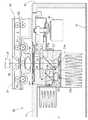
次に、フィルムスキャナ1の具体的な構造を図2〜4を用いて説明する。
図2に示すように、照明光学系20を下部に内蔵するとともに撮像光学系30と光電変換部40を上部に内蔵する筐体10によりフィルムスキャナ1の外観が構築されており、筐体10の中央部に形成されている凹部の下面にフィルムキャリヤユニット50が装着されるベース面10aが形成されている。Next, a specific structure of the film scanner 1 will be described with reference to FIGS.
As shown in FIG. 2, the exterior of the film scanner 1 is constructed by a
フィルムキャリアユニット50は、フィルム搬送方向を横断する方向(主走査方向)に延びているスリット状のスキャンゲート52が形成されたケース51を備えるとともに、そのケース51内に、写真フィルム2をフィルム搬送方向(副走査方向)に往復搬送するための複数の圧着型の搬送ローラ53と、ベース面10aに対向している集光レンズ54とを備えている。The
照明光学系20は、樹脂成形品で成る上壁部11と、アルミニウム合金で成る側壁部12と、同じくアルミニウム合金で成る底壁部13とでケース状に形成されている。前記上壁部11の内部には、基板にチップ状の多数の赤色の発光ダイオードを主走査方向に直線状に配列して構成されたR光源21aと、基板にチップ状の多数の緑色の発光ダイオードを主走査方向に直線状に配列して構成されたG光源21bと、基板にチップ状の多数の青色の発光ダイオードを主走査方向に直線状に配列して構成されたB光源21cとが取り付けられている。各光源21に対応する位置に各光源21からの光線を平行光線化するように各光源21に焦点位置を設定した平行化レンズ22を取り付けられ、これらの平行化レンズ22を介して送り出された光ビームを合流させるダイクロイック型のミラー23として第1ミラー23aと第2ミラーbが用意されている。 The illumination
G光源21bからの光ビームを上方に送る縦向き姿勢の第1光軸L1上に平行化レンズ22と第1ミラー23aとが配置され、B光源21cからの光ビームを上方に送る縦向き姿勢の第2光軸L2上に平行化レンズ22と第2ミラー23bとが配置され、R光源21aからの光ビームを水平方向に送る横向き姿勢の第3光軸L3上に平行化レンズ22と前記第1・第2ミラー23a、23bとが位置するようになっている。また、第1光軸L1の延長上で上壁11部の壁面の近傍位置には光線を拡散させて光量の分布を平均化させるディフューザ25が配置されている。つまり、第1、第2、第3光軸L1、L2、L3は、各色の光源21の形成方向(主走査方向)での中央位置で、かつ、基板に垂直となる仮想直線として設定されたものであり、第1光軸L1の延長上方にフィルムキャリヤユニット50の集光レンズ54とスキャンゲート52が位置し、第2光軸L2は第1ミラー23aにおいて第3光軸L3と合流する位置となっている。 A vertical orientation in which the
図3に示すように、第1光軸L1に沿って上方に送り出される光線の光量を低減する減光フィルタとしてのNDフィルタ24がフィルムキャリヤユニット50の集光レンズ54と向き合うように第1光軸L1上に選択的に位置決め可能に設けられている。このため、NDフィルタ24を支持する作動プレート14と、この作動プレート14に往復作動力を揺動アーム15を介して伝える駆動部としての電気モータ16が配置されている。このNDフィルタ24を図3に示す如く照明光学系20の光路中(第1光軸L1中)の減光位置にセットすることにより、照明光学系20から送り出される光線の光量を大きく減じ、このNDフィルタ24を光路外の待避位置に待避させることにより、照明光学系20からの光ビーム全てを送り出せる。本発明による光源光量調整作業時などでは、CCDセンサに過大な光量が入り込まないようにNDフィルタ24が光路中にセットされる。 As shown in FIG. 3, the first light is set so that the
なお、図3では、フィルム2がスキャンゲート52の近傍位置に存在する状態を示しており、この状態ではNDフィルタ24が待避位置に設定されるべきものであるが、NDフィルタ24よって光量を制限する状態を理解しやすくするため、同図では、NDフィルタ24を制限位置にセットした状態を示している。 FIG. 3 shows a state in which the
前記第1ミラー23aはG光源21bに用いられている青色の発光ダイオードからの波長(520〜560nm)の光線を透過し、これ以外の光線を反射する性能のものであり、前記第2ミラー23bはR光源21aに用いられている赤色の発光ダイオードからの波長(620〜750nm)の光線を透過し、B光源21cに用いられている青色の発光ダイオードからの波長(400〜480nm)の光線を反射する特性のものを使用している。 The
このような照明光学系20のレイアウトから、G光源21bから第1光軸L1に沿って送り出される光線は、平行化レンズ22で平行光線化した後に、第1ミラー23aを透過して第1光軸L1に沿って上方に送られ、B光源21cから第2光軸L1に沿って送り出される光線は、平行化レンズ22で平行光線化した後に、第2ミラー23bで反射して第3光軸L3と合流し、R光源21aから第3光軸L1に沿って送り出される光線は、平行化レンズ22で平行光線化した後に第2ミラー23bを透過するものとなり、このように第3光軸L3に沿って送られる青色成分の光ビームと、赤色成分の光ビームとは第1ミラー21aで反射され、第1光軸L1に沿って上方に送られる結果、この第1光軸L1ではR・G・Bの各光ビームが合流した白色の光ビームが送られ、ディフューザ25で拡散され、スキャンゲート52に導かれる。 From such a layout of the illumination
このフィルムスキャナ1でスキャニングを行う際には、取り込む画像の画素数に基づいてズームレンズ31による拡大率(主走査方向での画素数)を設定し、取り込む画像の画素数に基づいて搬送速度(副走査方向での画素数)を設定した後に、フィルムキャリアユニット50にフィルム2をセットし、フィルム2に対して照明光学系20からの光ビームを照射する状態で、搬送ローラ53の駆動でフィルム2を設定された速度で搬送し、この搬送速度と同期したタイミングで光電変換部40の各CCDセンサ41において主走査方向に沿うライン状に画像を取り込み、画像データ(輝度データ)として取得され、コントローラ60に送り込まれる。送り込まれた画像データ、つまりR画像データとG画像データとB画像データに対しては、前処理を経て種々の画像処理が施される。 When scanning with the film scanner 1, an enlargement ratio (number of pixels in the main scanning direction) by the
コントローラ60は、CPUを中核部材として、種々の動作を行うための機能部をハードウエア又はソフトウエアあるいはその両方で構築しているが、本発明に特に関するものとして、フィルムスキャナ1から送られてくる画像データをメモリ61に展開する画像入力部62と、フィルムスキャナ1に対する光源光量調整を行う光源光量調整手段80と、フィルムキャリアユニット50の搬送ローラ53を含むフィルムスキャナ1のスキャニング動作を制御するスキャナ制御部63と、メモリに展開された画像データに対して種々の画像処理を施す画像処理部64と、最終的に得られた撮影画像のための画像データを写真プリント装置70に対するプリントデータに変換生成するプリントデータ生成部65などが挙げられる。 The
光源光量調整手段80は、R・G・B光源21a、21b、21cの単独点灯時にCCDセンサ41によって取得され送り込まれてきた画像データから各CCDセンサ41のための測定光量値を算定しながら、R・G・B光源21a、21b、21cへのLED駆動電流である制御量を調整するものであり、全光源点灯時の測定光量値から各光源の光量値を推定する関係式を読み出し可能に格納する関係式格納部81と、各光源の目標光量値を設定する目標光量値設定部82と、前記目標光量値に適した前記光源に対する制御量を設定する制御量設定部83と、全光源点灯時に前記各光電変換センサによって取得された測定光量値から前記関係式を用いて各光源の推定光量値を算定する推定光量値算定部84と、前記推定光量値と前記目標光量値との差に応じて各光源に対する修正制御量を決定する制御量決定部85を備えている。 The light source light amount adjusting means 80 calculates the measured light amount value for each
関係式格納部81に格納される関係式とは、R・G・B光源21a、21b、21c全てを同時に点灯させた状態で各CCDセンサ41(R・CCDセンサ41a、G・CCDセンサ41b、B・CCDセンサ41c)で取得された測定光量値から、R・G・B光源21a、21b、21cそれぞれの光量値、つまりR・G・B光源21a、21b、21cを個別に点灯させた際に取得されるであろう光量値を推定する関係式のことである。 The relational expressions stored in the relational expression storage unit 81 are the CCD sensors 41 (R /
この関係式の一例を求める方法を、図6のフローチャートを参照しながら説明する。この関係式の原理は次の通りである。
R・G・B光源21a、21b、21cのそれぞれの照射光量値をR_led、G_led、B_ledとし、R・CCDセンサ41a、G・CCDセンサ41b、B・CCDセンサ41cそれぞれの受光光量値をR_ccd、G_ccd、B_ccdとして、R光源21aの照射光ビームに含まれているR成分の割合をβrr、G光源21bの照射光ビームに含まれているR成分の割合をβrg、B光源21cの照射光ビームに含まれているR成分の割合をβrbとすると、
R_ccd=βrr・R_led+βrg・G_led+βrb・B_led
が成立する。この式は、R・CCDセンサ41aで取得される光量値にはG光源21bやB光源21cの照射光に含まれているR成分も付加されることを意味している。同様に、R光源21aの照射光ビームに含まれているG成分の割合をβgr、G光源21bの照射光ビームに含まれているG成分の割合をβgg、B光源21cの照射光ビームに含まれているG成分の割合をβgbとし、R光源21aの照射光ビームに含まれているB成分の割合をβbr、G光源21bの照射光ビームに含まれているB成分の割合をβbg、B光源21cの照射光ビームに含まれているB成分の割合をβbbとすると、
G_ccd=βgr・R_led+βgg・G_led+βgb・B_led、
B_ccd=βbr・R_led+βbg・G_led+βbb・B_led
も成立する。
これらの式を行列を用いてまとめると次の第1式が得られる。
ここで、βに関する行列をβ変換行列と名付ける。
第1式を、β変換行列の逆行列を用いてR・G・B光源21a、21b、21cのそれぞれの照射光量値を表すR_led、G_led、B_ledで解くと、次の第2式が得られる。
この第2式は、全光源点灯時のR・CCDセンサ41a、G・CCDセンサ41b、B・CCDセンサ41cそれぞれの受光光量値を表すR_ccd、G_ccd、B_ccdによってR・G・B光源21a、21b、21cのそれぞれの照射光量値を求めることができる式となっているので、この式のβ変換行列の逆行列をα変換行列と置き換えると、CCDセンサ41の受光光量値から各光源21の照射光量値を求めることができる。つまり、α変換行列の各要素の値(β変換行列の逆行列の値)を予め求めておくことで、CCDセンサ41の受光光量値から各光源21の照射光量値を推定することができる。
つまり、上述した関係式を求めるということはα変換行列の各要素の値を求めることである。A method for obtaining an example of this relational expression will be described with reference to the flowchart of FIG. The principle of this relational expression is as follows.
The irradiation light quantity values of the R, G,
R_ccd = βrr ・ R_led + βrg ・ G_led + βrb ・ B_led
Is established. This equation means that the R component included in the irradiation light of the G
G_ccd = βgr ・ R_led + βgg ・ G_led + βgb ・ B_led,
B_ccd = βbr ・ R_led + βbg ・ G_led + βbb ・ B_led
Also holds.
When these equations are combined using a matrix, the following first equation is obtained.
Here, a matrix related to β is named a β conversion matrix.
Solving the first equation with R_led, G_led, and B_led representing the irradiation light quantity values of the R, G, and B
This second equation is obtained by R_ccd, G_ccd, B_ccd representing the received light amount values of the R /
In other words, obtaining the above-described relational expression means obtaining the value of each element of the α conversion matrix.
このα変換行列の各要素の値を求めるために、まずR・G・B光源21a、21b、21cのそれぞれに対する初期駆動電流量(ここでは初期制御量とも呼んでいる)をROMから読み出して設定する(#01)。R・G・B光源21a、21b、21cの内の1つの光源(例えばR光源21a)を選択して単独点灯する(#02)。点灯された光源21からの光ビームを各CCDセンサ41で100ライン分スキャニングし(#03)、取得した画像データをメモリ61に展開する(#04)。突出したノイズを抑制するため、メモリ61に展開された画像データ(R・G・B輝度データ)に対して平均値フィルタを用いて平滑化処理を施す(#05)。全画像データの値から暗データの値を差し引いて画素値を光源21による照射光に対応させる(#06)。なお、暗データはスキャナ技術においてよく知られているように、光源非点灯時におけるCCDセンサ41の読取信号値(画像データの画素値)である。この暗データは予め取得しておくが、よく知られているプロセスなのでここでの説明は省略する。そこで得られたR・G・B各画像データに含まれる全画素の値を平均して得られたR値とG値とB値を単独点灯された光源に対する各CCDセンサ41の受光光量値の基準として記憶する(#07)。単独点灯された光源に対する各CCDセンサ41の受光光量値の基準を記憶するルーチンをR・G・B光源21a、21b、21cのそれぞれに対して実行する(#08)。 In order to obtain the value of each element of the α conversion matrix, first, initial drive current amounts (also referred to as initial control amounts) for the R, G, and B
記憶されている値群を各光源21の単独点灯時における各CCDセンサ41の受光光量値群として、正規化のための以下の式を用いてβ変換行列の要素を演算する。
βrr=R光源単独点灯時のR値/R光源単独点灯時のR値、
βgr=R光源単独点灯時のG値/R光源単独点灯時のR値、
βbr=R光源単独点灯時のB値/R光源単独点灯時のR値、
βrg=G光源単独点灯時のR値/G光源単独点灯時のG値、
βgg=G光源単独点灯時のG値/G光源単独点灯時のG値、
βbg=G光源単独点灯時のB値/G光源単独点灯時のG値、
βrb=B光源単独点灯時のR値/B光源単独点灯時のB値、
βgb=B光源単独点灯時のG値/B光源単独点灯時のB値、
βbb=B光源単独点灯時のB値/B光源単独点灯時のB値。
例えば、R・G・B光源21a、21b、21cのそれぞれの単独点灯において得られたR値とG値とB値が、
とすると、
そのβ変換行列は、
となる(#09)。
その逆行列であるα変換行列は、
となる(#10)。
上述したように、α変換行列が得られるとその要素をテーブル化して関係式格納部81に格納する(#11)。このようにα変換行列の要素がテーブル化されていると、各CCDセンサ41の受光光量値(測定光量値とも呼ぶことができる)から各光源21の照射推定光量値を簡単な線形演算で求めることができる。Using the stored value group as the received light quantity value group of each
βrr = R value when the R light source is lit alone / R value when the R light source is lit alone,
βgr = G value when the R light source is lit alone / R value when the R light source is lit alone,
βbr = B value when R light source is lit alone / R value when R light source is lit alone,
βrg = R value when G light source is lit alone / G value when G light source is lit alone,
βgg = G value when G light source is lit alone / G value when G light source is lit alone,
βbg = B value when G light source is lit alone / G value when G light source is lit alone,
βrb = R value when the B light source is lit alone / B value when the B light source is lit alone,
βgb = G value when the B light source is lit alone / B value when the B light source is lit alone,
βbb = B value when the B light source is lit alone / B value when the B light source is lit alone.
For example, the R value, G value, and B value obtained in the individual lighting of each of the R, G,
Then,
The β transformation matrix is
(# 09).
The inverse matrix, the α transformation matrix, is
(# 10).
As described above, when the α conversion matrix is obtained, its elements are tabulated and stored in the relational expression storage unit 81 (# 11). When the elements of the α conversion matrix are tabulated in this way, the estimated irradiation light amount value of each
このフィルムスキャナ1に対して、最初に、全光源点灯時の測定光量値から各光源の光量値を推定する関係式、この実施形態ではα変換行列の要素を関係式格納部81に格納すると、日常的な光源光量調整はR・G・B光源21a、21b、21cを全て点灯させて(全灯状態)実施することができる。このような日常的な光源光量調整ルーチンを、図7のフローチャートを参照しながら説明する。
まず、全灯状態(つまり実際のスキャニングの状態)での各CCDセンサ41における目標(受光)光量値から関係式格納部81に格納されているデータを用いて各光源21の目標(照射)光量値を算定する(#20)。算定された目標(照射)光量値に基づいて制御量(各光源への駆動電流量)を決定し、設定する(#21)。設定された制御量で光源21を全灯し、この全灯状態で各CCDセンサの受光光量値として、前述した図6のフローチャートにおけるステップ#03〜#07に示す手順で得られる基準となるR・G・B別の測定光量値を求める(#22)。このステップは、R・CCDセンサ41a、G・CCDセンサ41b、B・CCDセンサ41cのそれぞれの受光光量値は、このフィルムスキャナ1を通じて取得されるカラー画像データを構成するR画像データの画素値(輝度値)、G画像データの画素値、B画像データの画素値に対応していることに基づいている。For this film scanner 1, first, when the relational expression for estimating the light quantity value of each light source from the measured light quantity value when all the light sources are turned on, in this embodiment, the elements of the α conversion matrix are stored in the relational expression storage unit 81. Routine light source light quantity adjustment can be performed by turning on all the R, G,
First, the target (irradiation) light amount of each
受光光量値(測定光量値)から再び関係式格納部81に格納されているデータを用いて各光源21の推定される(照射)光量値を算定する(#23)。ステップ#23で算定された推定(照射)光量値とステップ#20で取り扱われた目標(照射)光量値との差を制御偏差として求める(#24)。求めた制御偏差が一定範囲内に入っていると、この光源光量調整は終了する(#25Yes分岐)。求めた制御偏差が一定範囲内に入っていない場合(#25No分岐)、その制御偏差に応じて各光源21のための修正制御量が決定され、設定し直され(#26)、制御偏差が一定範囲内に入るまでステップ#22〜#26が繰り返される。その際、修正制御量を決定するルーチンが複数回行われることにより、修正制御量と推定光量値の複数の関係が得られた場合、一次近似式や二次近似式などの簡単な近似式を用いて推定(照射)光量値が目標(照射)光量値に最適に収束する修正制御量を決定するようにするとよい。 The estimated (irradiation) light quantity value of each
上述したように、全灯状態でのR・CCDセンサ41a、G・CCDセンサ41b、B・CCDセンサ41cそれぞれの受光光量値(測定受光量)からR・G・B光源21a、21b、21cのそれぞれの照射光量値を求めることができる関係式を予め関係式格納部81に格納しておくことにより、日常的に行われる光源光量調整は全灯状態で行うことができ、その結果、調整作業が迅速となるにもかかわらず、その精度は単灯状態を繰り返しながらの光量調整に匹敵するものとなる。 As described above, the R · G · B
上述した実施形態の説明では、スキャナとしてR・G・Bタイプのフィルムスキャナを採用していたが、少なくとも光の三原色のそれぞれに適応した複数の光源と複数の光電変換センサからなる全てのスキャナに本発明は適用可能である。 In the above description of the embodiment, the R, G, B type film scanner is used as the scanner. However, for all scanners composed of a plurality of light sources and a plurality of photoelectric conversion sensors adapted to each of the three primary colors of light. The present invention is applicable.
1:フィルムスキャナ(スキャナ)
60:コントローラ
61:メモリ
80:光源光量調整手段
81:関係式格納部
82:目標光量値設定部
83:制御量決定部
84:推定光量値算定部
85:制御量決定部1: Film scanner (scanner)
60: Controller 61: Memory 80: Light source light amount adjustment means 81: Relational expression storage unit 82: Target light amount value setting unit 83: Control amount determination unit 84: Estimated light amount value calculation unit 85: Control amount determination unit
Claims (6)
Translated fromJapanese各前記光源の単独点灯時に各前記光電変換センサによって取得された測定光量値に基づいて全前記光源点灯時の測定光量値から各前記光源の光量値を推定する関係式を求めるステップと、
各前記光源の目標光量値を設定するステップと、
前記目標光量値に適した前記光源に対する制御量を設定するステップと、
全前記光源点灯時に各前記光電変換センサによって取得された測定光量値から前記関係式を用いて各前記光源の推定光量値を算定するステップと、
前記推定光量値と前記目標光量値との差に応じて各前記光源に対する修正制御量を決定するステップと、
からなることを特徴とする光源光量調整方法。AnR light source composed of an LED element array that emits a red component light beam, a G light source composed of an LED element array that emits a green component light beam, and a blue component light beam adapted to each of the three primary colorsof light. In a light source light quantity adjustment method for a scannercomprising a lightsource comprising a B light source comprising a radiating LED element array, and a photoelectric conversion sensor comprising an R photoelectric conversion sensor, a G photoelectric conversion sensor, and an R photoelectric conversion sensor ,
Determining a relational expression for estimating the light intensity value of each ofthe light sources from the measured light intensity values of allthe light sources lit on the basis of the obtained measured light value byeach of said photoelectric conversion sensors in a single time of lighting of thelight source,
Setting a target light amount value of each ofthe light sources,
Setting a control amount for the light source suitable for the target light amount value;
A step of calculating the estimated light intensity values of each ofthe light sources by using the relational expression from the measured light value obtained byeach of said photoelectric conversion sensor when allthe light source lighting,
Determining a corrected control amount of eachlight source in accordance with the difference between the target light quantity and the estimated quantity value,
The light source light quantity adjustment method characterized by comprising.
各前記光源の単独点灯時に各前記光電変換センサによって取得された測定光量値に基づいて求められた、全前記光源点灯時の測定光量値から各前記光源の光量値を推定する関係式を読み込む機能と、
各前記光源の目標光量値を設定する機能と、
前記目標光量値に適した前記光源に対する制御量を設定する機能と、
全前記光源点灯時に各前記光電変換センサによって取得された測定光量値から前記関係式を用いて各前記光源の推定光量値を算定する機能と、
前記推定光量値と前記目標光量値との差に応じて各前記光源に対する修正制御量を決定する機能と、
をコンピュータに実現させる光源光量調整プログラム。AnR light source composed of an LED element array that emits a red component light beam, a G light source composed of an LED element array that emits a green component light beam, and a blue component light beam adapted to each of the three primary colorsof light. In a light source light quantity adjustment program for a scannercomprising a lightsource comprising a B light source comprising a radiating LED element array, and a photoelectric conversion sensor comprising an R photoelectric conversion sensor, a G photoelectric conversion sensor, and an R photoelectric conversion sensor ,
Obtained based on the measured light intensity values obtained byeach of said photoelectric conversion sensors in a single time of lighting of each ofthe light sources, ability to read a relational expression for estimating the light intensity value of each ofthe light sources from the measured light quantity value at fulllight source lighting When,
A function of setting a target light amount value of each ofthe light sources,
A function of setting a control amount for the light source suitable for the target light amount value;
A function to calculate the estimated light intensity values of each ofthe light sources by using the relational expression from allthe light source measured light value obtained byeach of said photoelectric conversion sensor when lit,
A function of determining a correction control amount for eachsaid light source in accordance with the difference between the target light quantity and the estimated quantity value,
A light source light quantity adjustment program that makes a computer realize.
各前記光源の単独点灯時に各前記光電変換センサによって取得された測定光量値に基づいて求められた、全前記光源点灯時の測定光量値から各前記光源の光量値を推定する関係式を読み出し可能に格納する関係式格納部と、
各前記光源の目標光量値を設定する目標光量値設定部と、
前記目標光量値に適した前記光源に対する制御量を設定する制御量設定部と、
全前記光源点灯時に各前記光電変換センサによって取得された測定光量値から前記関係式を用いて各前記光源の推定光量値を算定する推定光量値算定部と、
前記推定光量値と前記目標光量値との差に応じて各前記光源に対する修正制御量を決定する
制御量決定部と、
からなることを特徴とする光源光量調整システム。AnR light source composed of an LED element array that emits a red component light beam, a G light source composed of an LED element array that emits a green component light beam, and a blue component light beam adapted to each of the three primary colorsof light. In a light source light quantity adjustment system for a scannercomprising a lightsource comprising a B light source comprising a radiating LED element array, and a photoelectric conversion sensor comprising an R photoelectric conversion sensor, a G photoelectric conversion sensor, and an R photoelectric conversion sensor ,
Obtained based on the measured light intensity values obtained byeach of said photoelectric conversion sensors in a single time of lighting of thelight source, can be read relational expression for estimating the light intensity value of each ofthe light sources from the measured light quantity value at fulllight source lighting A relational expression storage unit stored in
A target light amount value setting unit for setting a target light amount value of each ofsaid light sources,
A control amount setting unit for setting a control amount for the light source suitable for the target light amount value;
And estimated quantity value calculation unit to calculate the estimated light intensity values of each ofthe light sources by using the relational expression from allthe light source measured light value obtained byeach of said photoelectric conversion sensor when lit,
A control amount determining unit which determines a corrected control amount of eachlight source in accordance with the difference between the target light quantity and the estimated quantity value,
The light source light quantity adjustment system characterized by comprising.
Priority Applications (1)
| Application Number | Priority Date | Filing Date | Title |
|---|---|---|---|
| JP2004191533AJP4596239B2 (en) | 2004-06-29 | 2004-06-29 | Light source light amount adjustment method, light source light amount adjustment program and light source light amount adjustment system for scanner |
Applications Claiming Priority (1)
| Application Number | Priority Date | Filing Date | Title |
|---|---|---|---|
| JP2004191533AJP4596239B2 (en) | 2004-06-29 | 2004-06-29 | Light source light amount adjustment method, light source light amount adjustment program and light source light amount adjustment system for scanner |
Publications (2)
| Publication Number | Publication Date |
|---|---|
| JP2006011263A JP2006011263A (en) | 2006-01-12 |
| JP4596239B2true JP4596239B2 (en) | 2010-12-08 |
Family
ID=35778576
Family Applications (1)
| Application Number | Title | Priority Date | Filing Date |
|---|---|---|---|
| JP2004191533AExpired - Fee RelatedJP4596239B2 (en) | 2004-06-29 | 2004-06-29 | Light source light amount adjustment method, light source light amount adjustment program and light source light amount adjustment system for scanner |
Country Status (1)
| Country | Link |
|---|---|
| JP (1) | JP4596239B2 (en) |
Families Citing this family (6)
| Publication number | Priority date | Publication date | Assignee | Title |
|---|---|---|---|---|
| JP4726512B2 (en)* | 2005-02-23 | 2011-07-20 | キヤノン電子株式会社 | Image reading apparatus and control method thereof, light amount adjustment method of image reading unit having image reading sensor, program, and storage medium |
| JP4581875B2 (en)* | 2005-07-15 | 2010-11-17 | ノーリツ鋼機株式会社 | Image sensor correction table creation method |
| JP2013121113A (en)* | 2011-12-08 | 2013-06-17 | Nec Access Technica Ltd | Original reader, light amount adjustment method on original reading and light amount adjustment program |
| WO2014083970A1 (en)* | 2012-11-30 | 2014-06-05 | 日本電気株式会社 | Image display device and image display method |
| JP7331519B2 (en)* | 2019-07-23 | 2023-08-23 | 沖電気工業株式会社 | Image reading device, coin recognition device using the image reading device, and coin handling device |
| JP6874087B2 (en)* | 2019-10-09 | 2021-05-19 | 富士フイルム株式会社 | Endoscope system and how to operate the endoscope system |
Family Cites Families (5)
| Publication number | Priority date | Publication date | Assignee | Title |
|---|---|---|---|---|
| JPH0822081A (en)* | 1994-07-08 | 1996-01-23 | Fuji Photo Film Co Ltd | Photographic printer and film scanner |
| JPH1021371A (en)* | 1996-07-05 | 1998-01-23 | Tamron Co Ltd | Image input device |
| JP2000101787A (en)* | 1998-07-22 | 2000-04-07 | Fuji Photo Film Co Ltd | Picture reading method and device therefor |
| JP2001281579A (en)* | 2000-03-30 | 2001-10-10 | Minolta Co Ltd | Light beam scanner and inage forming device provided with the same |
| JP2002237922A (en)* | 2001-02-09 | 2002-08-23 | Canon Inc | Image reading apparatus, control method thereof, and storage medium |
- 2004
- 2004-06-29JPJP2004191533Apatent/JP4596239B2/ennot_activeExpired - Fee Related
Also Published As
| Publication number | Publication date |
|---|---|
| JP2006011263A (en) | 2006-01-12 |
Similar Documents
| Publication | Publication Date | Title |
|---|---|---|
| US6751349B2 (en) | Image processing system | |
| JP4083042B2 (en) | Image reading apparatus and image reading method | |
| US7022960B2 (en) | Photographic film image reading apparatus with film density detection | |
| EP0785671B1 (en) | Image reading apparatus | |
| JP4596239B2 (en) | Light source light amount adjustment method, light source light amount adjustment program and light source light amount adjustment system for scanner | |
| US20120026353A1 (en) | System comprising two lamps and an optical sensor | |
| US6972877B1 (en) | Image reading apparatus | |
| JP4385292B2 (en) | Color image data correction method and correction system for implementing the method | |
| US7324243B2 (en) | Fluorescent color scanning method for use in a scanner | |
| US8570615B2 (en) | Image scanning device | |
| JP4399722B2 (en) | Light source adjustment method for a scanner with a neutral density filter | |
| JP2001111795A (en) | Image reader | |
| US20030142208A1 (en) | Image reading apparatus | |
| JP5233641B2 (en) | Image reading apparatus, copier equipped with the same, and image reading method | |
| JP2007006114A (en) | Light source light quantity adjustment method and light source light quantity adjustment module | |
| US20050117181A1 (en) | Film image scanning system and light source unit for scanning a film | |
| US7202461B2 (en) | Image-reading apparatus | |
| JP2007036964A (en) | Image reading apparatus adjustment method and adjustment module | |
| US6906833B1 (en) | Constant speed image reading device and method | |
| JP2001045225A (en) | Image reader | |
| JP2007006354A (en) | Image reading apparatus and image reading apparatus adjustment program | |
| JP2005252651A (en) | Image reader | |
| JP2007036431A (en) | Film scanner | |
| JP3683709B2 (en) | Image reading device | |
| JP2006121598A (en) | Film scanner and shading correction method for film scanner |
Legal Events
| Date | Code | Title | Description |
|---|---|---|---|
| A621 | Written request for application examination | Free format text:JAPANESE INTERMEDIATE CODE: A621 Effective date:20070606 | |
| A977 | Report on retrieval | Free format text:JAPANESE INTERMEDIATE CODE: A971007 Effective date:20100521 | |
| A131 | Notification of reasons for refusal | Free format text:JAPANESE INTERMEDIATE CODE: A131 Effective date:20100527 | |
| A521 | Request for written amendment filed | Free format text:JAPANESE INTERMEDIATE CODE: A523 Effective date:20100726 | |
| TRDD | Decision of grant or rejection written | ||
| A01 | Written decision to grant a patent or to grant a registration (utility model) | Free format text:JAPANESE INTERMEDIATE CODE: A01 Effective date:20100826 | |
| A01 | Written decision to grant a patent or to grant a registration (utility model) | Free format text:JAPANESE INTERMEDIATE CODE: A01 | |
| A61 | First payment of annual fees (during grant procedure) | Free format text:JAPANESE INTERMEDIATE CODE: A61 Effective date:20100908 | |
| R150 | Certificate of patent or registration of utility model | Free format text:JAPANESE INTERMEDIATE CODE: R150 | |
| FPAY | Renewal fee payment (event date is renewal date of database) | Free format text:PAYMENT UNTIL: 20131001 Year of fee payment:3 | |
| S111 | Request for change of ownership or part of ownership | Free format text:JAPANESE INTERMEDIATE CODE: R313111 | |
| FPAY | Renewal fee payment (event date is renewal date of database) | Free format text:PAYMENT UNTIL: 20131001 Year of fee payment:3 | |
| R350 | Written notification of registration of transfer | Free format text:JAPANESE INTERMEDIATE CODE: R350 | |
| R250 | Receipt of annual fees | Free format text:JAPANESE INTERMEDIATE CODE: R250 | |
| R250 | Receipt of annual fees | Free format text:JAPANESE INTERMEDIATE CODE: R250 | |
| LAPS | Cancellation because of no payment of annual fees | ||
| S533 | Written request for registration of change of name | Free format text:JAPANESE INTERMEDIATE CODE: R313533 | |
| R350 | Written notification of registration of transfer | Free format text:JAPANESE INTERMEDIATE CODE: R350 |