JP4596033B2 - Document reader - Google Patents
Document readerDownload PDFInfo
- Publication number
- JP4596033B2 JP4596033B2JP2008104699AJP2008104699AJP4596033B2JP 4596033 B2JP4596033 B2JP 4596033B2JP 2008104699 AJP2008104699 AJP 2008104699AJP 2008104699 AJP2008104699 AJP 2008104699AJP 4596033 B2JP4596033 B2JP 4596033B2
- Authority
- JP
- Japan
- Prior art keywords
- document
- reading
- unit
- guide
- scanner
- Prior art date
- Legal status (The legal status is an assumption and is not a legal conclusion. Google has not performed a legal analysis and makes no representation as to the accuracy of the status listed.)
- Expired - Fee Related
Links
Images


Landscapes
- Facsimiles In General (AREA)
- Facsimile Scanning Arrangements (AREA)
Description
Translated fromJapanese本発明は両面読取機能を備えた原稿読取装置に関するものであり、詳細には、原稿読取装置の開閉機構及び原稿搬送経路の構成に関するものである。 The present invention relates to a document reading apparatus having a double-sided reading function, and more particularly to the configuration of an opening / closing mechanism and a document transport path of the document reading apparatus.
従来から、原稿の第1面を読み取るための第1の読取部を本体側に備え、原稿の第2面を読み取るための第2の読取部を自動原稿搬送装置側に備えた、所謂ワンパス方式の原稿読取装置が知られている。この種の原稿読取装置を開示したものに例えば特許文献1がある。特許文献1が開示する原稿読取装置は、第1の読取部においてCCDイメージセンサ等からなる縮小光学系の読取装置を用い、第2の読取部において密着型イメージセンサを用いている。この構成で、原稿読取装置に供給された原稿は、原稿読取装置内に形成される原稿搬送経路に従って第1の読取部及び第2の読取部へと搬送され、両面が読み取られる。
ところで、両面読取機能を備える原稿読取装置においては、特許文献1のような密着型イメージセンサを備える第2の読取部に代えて、例えばCCDイメージセンサからなる縮小光学系の読取部を用いる場合がある。しかし、この縮小光学系の読取部は所定の光路長を確保する必要があるため、密着型イメージセンサを用いる場合等に比べて第2の読取部及びそれを保持するスキャナフレームの構成が大きくなってしまう。 By the way, in a document reading apparatus having a double-sided reading function, instead of a second reading unit having a contact image sensor as in Patent Document 1, for example, a reading unit of a reduction optical system including a CCD image sensor may be used. is there. However, since the reading unit of the reduction optical system needs to ensure a predetermined optical path length, the configuration of the second reading unit and the scanner frame that holds the second reading unit is larger than when a contact image sensor is used. End up.
また、原稿読取装置は、ジャム原稿を取り除く等の各種メンテナンス作業を容易にするために、当該原稿読取装置の内部を開放する開閉機構を備えることがある。しかし、第2の読取部を縮小光学系の構成とした場合は、前述したように読取部の構成が大きくなるため、開閉のための十分なスペースを原稿読取装置内に確保することが難しかった。従って、特許文献1に開示するような従来の原稿読取装置において単に縮小光学系の読取部を適用するだけでは、装置の開閉を実現するための十分なスペースを確保できず、原稿読取装置の大型化を招くおそれがあった。 Further, the document reading device may include an opening / closing mechanism that opens the inside of the document reading device in order to facilitate various maintenance operations such as removing a jammed document. However, when the second reading unit is configured as a reduction optical system, the configuration of the reading unit is large as described above, and it is difficult to secure a sufficient space for opening and closing in the document reading apparatus. . Therefore, simply applying the reading unit of the reduction optical system in the conventional document reading device disclosed in Patent Document 1 cannot secure a sufficient space for opening and closing the device, and the size of the document reading device is large. There was a risk of inducing.
本発明は以上の事情に鑑みてなされたものであり、その目的は、縮小光学系の第2の読取部を備える原稿読取装置において、原稿読取装置内のスペースを有効に活用して開閉機構を実現する構成を提供することにある。 The present invention has been made in view of the above circumstances, and an object of the present invention is to provide an opening / closing mechanism in a document reading apparatus having a second reading unit of a reduction optical system by effectively utilizing the space in the document reading apparatus. It is to provide a configuration to be realized.
本発明の解決しようとする課題は以上の如くであり、次にこの課題を解決するための手段とその効果を説明する。 The problems to be solved by the present invention are as described above. Next, means for solving the problems and the effects thereof will be described.
本発明の観点によれば、以下の構成の原稿読取装置が提供される。即ち、この原稿読取装置は、ローラと、第1の読取部と、縮小光学系の第2の読取部と、スキャナフレームと、原稿ガイドと、を備える。前記ローラは、折返し部を有するU字状の原稿搬送経路に配置される。前記第1の読取部は、前記原稿搬送経路に沿って搬送される前記原稿の第1面を読み取るために前記原稿搬送経路の外側に配置される。前記第2の読取部は、前記原稿の第2面を読み取るために前記原稿搬送経路の内側に配置される。前記スキャナフレームは、前記ローラの軸線を回動中心として、前記原稿を読み取るときの使用位置から前記第2の読取部の読取部分が露出する露出位置に回動可能であるとともに、前記ローラより前記折返し部に近い側に、前記第2の読取部が有する光路を構成する反射ミラーが配置される。前記第2の読取部は、前記スキャナフレームの内部に配置されている。前記原稿ガイドは、前記第1の読取部の読取部分から前記第2の読取部の読取部分へ前記原稿搬送経路に従って前記原稿をガイドする。前記原稿ガイドは、第1案内部と、第2案内部と、を備える。前記第1案内部は、前記原稿搬送経路の下流側へ行くに従って、前記第2の読取部の読取部分が配置されている高さ近傍まで上昇するように形成される。前記第2案内部は、前記第1案内部の下流側に配置され、その向きを前記第1案内部よりも水平に近づけながら下流側へと延びるように形成される。According to an aspect of the present invention, a document reading apparatus having the following configuration is provided. That is, the document reading apparatus includes a roller, a first reading unit, a second reading unit of a reduction optical system, a scanner frame, and a document guide. The roller is disposed in a U-shaped document conveyance path having a folded portion. The first reading unit is disposed outside the document conveyance path in order to read the first surface of the document conveyed along the document conveyance path. The second reading unit is disposed inside the document transport path to read the second surface of the document. The scanner frame is rotatable about a rotation axis of the roller from a use position when reading the document to an exposed position where a reading portion of the second reading unit is exposed.A reflection mirror constituting the optical pathof the second reading unit is disposed on the side close to the folding unit.The second reading unit is disposed inside the scanner frame. The document guide guides the document from the reading portion of the first reading unit to the reading portion of the second reading unit along the document transport path. The document guide includes a first guide unit and a second guide unit. The first guide portion is formed so as to rise to the vicinity of the height at which the reading portion of the second reading portion is arranged as it goes downstream of the document conveyance path. The second guide portion is disposed on the downstream side of the first guide portion, and is formed to extend toward the downstream side while approaching the horizontal direction of the first guide portion.
これにより、第2の読取部の光路が原稿搬送経路の内側(折返し部側)に差し込まれるようにスキャナフレームを配置することができ、原稿読取装置内のスペースを有効に活用することができる。また、原稿ガイドの第2案内部は第1案内部よりも向きを水平に近づけるように形成されているので、第1の読取部から第2の読取部まで原稿ガイドが直線状に形成される場合に比べて、原稿読取装置内の高さ方向のスペースを有効に使うことができる。更に、スキャナフレームの回動中心がローラと同軸上にあるので、構成を簡素化することができ、製造コスト及び製造工数を低減することができる。 As a result, the scanner frame can be arranged so that the optical path of the second reading unit is inserted inside the document conveyance path (on the folding unit side), and the space in the document reading apparatus can be used effectively. In addition, since the second guide portion of the document guide is formed so as to be closer to the horizontal than the first guide portion, the document guide is formed linearly from the first reading portion to the second reading portion. Compared to the case, the space in the height direction in the document reading apparatus can be used effectively. Furthermore, since the rotation center of the scanner frame is coaxial with the roller, the configuration can be simplified, and the manufacturing cost and the number of manufacturing steps can be reduced.
前記の原稿読取装置においては、以下の構成とすることが好ましい。即ち、前記スキャナフレームは、前記第2の読取部の読取部分から前記折返し部に近い側の少なくとも一部において、当該折返し部に近づくに従って前記原稿搬送経路から離れるようなフレーム面を有している。前記第1案内部は湾曲状に構成されている。前記フレーム面、前記第1案内部及び前記第2案内部がY字状に接続される。 The document reading apparatus preferably has the following configuration. In other words, the scanner frame has a frame surface at least part of the second reading unit on the side closer to the folding unit, such that the scanner frame moves away from the document conveyance path as it approaches the folding unit. . The first guide part is formed in a curved shape. The frame surface, the first guide part, and the second guide part are connected in a Y shape.
これにより、Y字の合流地点まではフレーム面及び第1案内部の湾曲部分が互いに離れているので、スキャナフレームの回動時に原稿ガイドに干渉することなくスキャナフレームを露出位置まで回動させることができる。また、第1案内部が湾曲しながら上昇しているので、原稿の引っ掛かりを防止しながらスムーズに原稿を上昇させて下流側へ搬送することができる。 As a result, since the frame surface and the curved portion of the first guide part are separated from each other up to the Y junction, the scanner frame can be rotated to the exposure position without interfering with the document guide when the scanner frame is rotated. Can do. In addition, since the first guide portion is raised while being curved, the document can be smoothly raised and conveyed downstream while preventing the document from being caught.
前記の原稿読取装置においては、前記第2案内部が水平な直線状に形成されることが好ましい。 In the document reading apparatus, it is preferable that the second guide portion is formed in a horizontal linear shape.
これにより、原稿読取装置内の高さ方向のスペースを更に有効に利用できるので、原稿読取装置を特に高さ方向で一層コンパクトに構成することができる。 As a result, the space in the height direction in the document reading apparatus can be used more effectively, so that the document reading apparatus can be made more compact particularly in the height direction.
前記の原稿読取装置においては、前記第2案内部に対面するように前記第2の読取部の読取部分が位置することが好ましい。 In the document reading apparatus, it is preferable that the reading portion of the second reading unit is positioned so as to face the second guide unit.
これにより、原稿を水平方向に搬送しながら第2の読取部で読み取る形になるので、原稿を安定的かつ正確に読み取ることができる。 As a result, the document is read by the second reading unit while being conveyed in the horizontal direction, so that the document can be read stably and accurately.
前記の原稿読取装置においては、前記第1案内部に回転ローラが配置されることが好ましい。 In the document reading apparatus, it is preferable that a rotation roller is disposed in the first guide portion.
これにより、第1の読取部の読取部分から搬送されてきた原稿を、回転ローラによって確実に下流側へ導くことができる。また、回転ローラは第1案内部に配置されるので、回転ローラを他の構成の邪魔になることなく合理的に配置できる。 Thereby, the document conveyed from the reading portion of the first reading unit can be reliably guided to the downstream side by the rotating roller. Further, since the rotating roller is disposed in the first guide portion, the rotating roller can be reasonably disposed without interfering with other configurations.
以下、本発明の好適な実施形態について図面を参照しながら説明する。図1は本発明の一実施形態に係る原稿読取装置としてのイメージスキャナ装置10を含む、コピーファクシミリ複合機(複合機)20の外観斜視図である。図2は、本実施形態のイメージスキャナ装置の構成を示した正面断面図である。なお、以下の説明において「水平」とは、装置の設置面と平行な方向を意味する。 Preferred embodiments of the present invention will be described below with reference to the drawings. FIG. 1 is an external perspective view of a copy facsimile multifunction peripheral (multifunction peripheral) 20 including an
図1に示すコピーファクシミリ複合機20は、ブックスキャナ及びオートドキュメントフィードスキャナとして機能するイメージスキャナ装置10を、当該複合機20の上部に備えている。また、複合機20は、コピー部数、ファクシミリ送信先及び原稿読取等を指示するための操作パネル77を備える。 A copy
更に、複合機20は、記録媒体としての用紙に画像を形成する画像形成部等を内蔵した本体78と、前記用紙を順次供給する給紙カセット79と、を備えている。この本体78は、通信回線を介して画像データを伝送するための図略の送受信部等を備える。 Further, the
次に図2を参照して、前記複合機20が備えるイメージスキャナ装置10について説明する。図2に示すように、イメージスキャナ装置10は、プラテンガラス22と原稿台カバー21とを備えている。この原稿台カバー21には自動原稿搬送装置(オートドキュメントフィーダ、ADF)25が備えられている。また、イメージスキャナ装置10は、原稿の画像を読み取るための第1スキャナユニット(第1の読取部)50及び第2スキャナユニット(第2の読取部)60を備えている。 Next, the
このイメージスキャナ装置10をオートドキュメントフィードスキャナとして使用する場合は、前記ADF25によって原稿を1枚ずつ搬送する。そして、原稿の表側の面(第1面)の画像は第1スキャナユニット50によって読み取られ、裏側の面(第2面)の画像は第2スキャナユニット60によって読み取られる。 When the
一方、イメージスキャナ装置10をブックスキャナとして使用する場合は、読み取るべきブック原稿をユーザがプラテンガラス22上に載置して、その上から原稿台カバー21によって押圧し、ブック原稿が動かないように固定する。この状態で、第1スキャナユニット50によって原稿の画像を読み取ることができるようになっている。 On the other hand, when the
図2に示すように、前記原稿台カバー21が備えるADF25は、原稿台カバー21の上部に設けられた原稿トレイ23と、この原稿トレイ23の下方に設けられた排出トレイ24と、を備える。また、ADF25は、ADF本体部16と、その上側を覆うカバー部11とを備えている。このカバー部11は、カバー回動軸43を介してADF本体部16に回動可能に支持されている。 As shown in FIG. 2, the
図2に示すように、前記原稿台カバー21の内部には、原稿トレイ23と排出トレイ24とを繋ぐ湾曲状(正面氏で横向きU字状)の原稿搬送経路30が構成されている。この構成で、原稿トレイ23に重ねてセットされた原稿は、1枚ずつ分離されて湾曲状の前記原稿搬送経路30に沿って搬送され、排出トレイ24へ排出される。原稿の読取の開始等の指示は、図1に示す操作パネル77によって行うことができる。 As shown in FIG. 2, a
次に、原稿搬送経路30に沿って、ADF25の各部の構成を詳細に説明する。 Next, the configuration of each part of the
図2に示すように、原稿トレイ23から原稿搬送経路30に原稿が供給される箇所にはピックアップローラ31が配置されている。このピックアップローラ31の下流側には分離ローラ32が備えられ、この分離ローラ32に対向して対向ローラ37が配置されている。 As shown in FIG. 2, a
この構成で、ピックアップローラ31が駆動されることによって、原稿トレイ23上の最上層の原稿がADF25内に繰り込まれる。原稿はピックアップローラ31の駆動によって分離ローラ32へ送られ、当該分離ローラ32と対向ローラ37との間にニップされる。そして原稿は、回転駆動する分離ローラ32によって1枚ずつ分離され、原稿搬送経路30の下流側へ搬送される。 With this configuration, when the
分離ローラ32の下流側には、レジストローラ39と、このレジストローラ39と対になる対向ローラと、が配置されている。レジストローラ39は前記対向ローラとともに、分離ローラ32によって搬送されてくる原稿の先頭側を一時的に止めて弛ませ、所定時間後に弛みを除去しつつ下流側に搬送する。これにより、原稿の斜行が矯正される。 On the downstream side of the
レジストローラ39の下流側には、複数の搬送ローラ33,34,35が設けられる。また、この搬送ローラ33,34,35のそれぞれに対向するようにローラが配置されている。前記レジストローラ39の駆動によって下流側へ搬送された原稿は、搬送ローラ33,34,35とそれらに対向するローラとによりニップされて、更に下流側へ搬送される。 A plurality of conveying
2つの搬送ローラ34,35の間には第1原稿読取位置80が設定されており、この第1原稿読取位置80にはコンタクトガラス44及びプラテンローラ29が配置されている。そして、この第1原稿読取位置80を通過する原稿は、後述の第1スキャナユニット50によって走査され、読み取られる。なお、前記搬送ローラ33から第1原稿読取位置80までの間において、原稿搬送経路30には、原稿の搬送方向を反転させる折返し部45が形成されている。 A first
第1スキャナユニット50について説明する。この第1スキャナユニット50は本体78側に設置されるとともに、ADF25及びプラテンガラス22の下方に配置されている。また、この第1スキャナユニット50は、光源51と、反射ミラー52,53,54と、集光レンズ55と、電荷結合素子(CCD)56と、を備えている。光源51は、前記ADF25の前記第1原稿読取位置80に配置された読取部分としてのコンタクトガラス44(又はプラテンガラス22)に対して光を照射し、反射ミラー52,53,54は原稿からの反射光を反射させる。そしてこの反射光を集光レンズ55で収束させて、この収束光がCCD56の部分で結像するように構成されている。 The
第1スキャナユニット50の光源51及び反射ミラー52等は移動可能に構成されている。前述したようにイメージスキャナ装置10をブックスキャナとして使用する場合は、第1スキャナユニット50の光源51及び反射ミラー52等をプラテンガラス22に沿って移動させる。これによって、プラテンガラス22上に載置された原稿を読み取ることができるようになっている。 The
一方、イメージスキャナ装置10をオートドキュメントフィードスキャナとして使用する場合は、光源51及び反射ミラー52等は、図2に示すように、前記第1原稿読取位置80に対向する位置まで移動させて静止させておく。この状態でADF25を駆動することにより、原稿搬送経路30を搬送されて第1原稿読取位置80を通過する原稿の表側の面を、第1スキャナユニット50が走査して読み取ることができる。 On the other hand, when the
第1スキャナユニット50において、原稿からの反射光は前述のとおりCCD56へ導かれて結像し、CCD56は原稿の画像情報に応じた電気信号を出力する。この信号は適宜変換処理され、複合機20が備える画像形成部に送信される。そして、この送信された画像情報が画像形成部によって記録媒体としての用紙に転写されることで、複合機20のコピー機能等が実現される。 In the
原稿搬送経路30において、前記第1原稿読取位置80の下流側(搬送ローラ35の下流側)には第2原稿読取位置90が設定されている。また、第1原稿読取位置80の下流側には、原稿搬送経路30に沿って形成された原稿ガイド13が配置されている。原稿ガイド13は、第1原稿読取位置80から第2原稿読取位置90まで(前記コンタクトガラス44から後述の読取ガラス42まで)の間で原稿を案内するためのものであり、ADF本体部16に取り付けられている。なお、原稿ガイド13の詳細については後述する。 In the
前記第2原稿読取位置90まで搬送された原稿の裏面は、次に説明する第2スキャナユニット60によって走査されて読み取られる。 The back side of the original conveyed to the second
第2スキャナユニット60について説明する。この第2スキャナユニット60は、U字状に構成された前記原稿搬送経路30に内側から接するように、当該原稿搬送経路30の内側に設置されている。また、第2スキャナユニット60は、ADF25の内部に保持されたスキャナフレーム12を備えている。このスキャナフレーム12は、内部の光学系を構成する部品等を支持するとともに、その外側を覆って保護するように構成されている。 The
スキャナフレーム12の底部(原稿搬送経路30に接する部分)には、原稿の裏面を読み取るための読取ガラス42(読取部分)が備えられる。この読取ガラス42は、前記第2原稿読取位置90に対応する位置に配置される。また、図2に示すように、この読取ガラス42は、前述したレジストローラ39よりも前記折返し部45から若干遠い側に配置されている。更に、前記読取ガラス42は、前記第1スキャナユニット50のコンタクトガラス44よりも高い位置に配置されている。 A reading glass 42 (reading portion) for reading the back side of the document is provided at the bottom of the scanner frame 12 (the portion in contact with the document conveyance path 30). The reading
また、スキャナフレーム12の前記第2原稿読取位置90に対向するように、プラテンローラ38がADF25本体部分に配置されている。この構成で、前記搬送ローラ35により搬送された原稿がプラテンローラ38の部分に差し掛かると、当該原稿はプラテンローラ38により搬送されながらその裏側の面が走査されて読み取られる。 Further, a
以上のようにして2つの原稿読取位置で表裏両面の内容を読み取られた原稿は、排出ローラ36によって搬送され、排出トレイ24へ排出される。このようにして、原稿搬送経路30に原稿を1回通過させるだけで両面読取が可能な構成の、いわゆるワンパス方式のADF25が構成されている。 The document whose contents on both the front and back sides are read at the two document reading positions as described above is conveyed by the
次にスキャナフレーム12、第2スキャナユニット60及び原稿ガイド13について説明する。前述したように、スキャナフレーム12はADF本体部16内に保持されている。また、スキャナフレーム12の下面には、読取ガラス42より原稿搬送経路30上流側(前記折返し部45に近い側であって、図2における紙面左側)の部分において、上方に湾曲するフレーム面14が形成されている。このフレーム面14は、前記折返し部45に近づくに従って前記原稿搬送経路30から徐々に離れるような面として構成されている。以上の構成のスキャナフレーム12により密閉空間が形成され、この空間の内部に、第2スキャナユニット60の光路を構成する部品が配置されている。 Next, the
また、スキャナフレーム12には押圧ローラ40が回転可能に支持され、この押圧ローラ40は、前記排出ローラ36に対向するようにしてスキャナフレーム12の底部に配置されている。この構成で、第2スキャナユニット60で読み取られた原稿は、前記押圧ローラ40と排出ローラ36との間でニップされ、排出ローラ36の駆動によって排出トレイ24へ導かれる。 A
前記スキャナフレーム12は、レジストローラ39を支持するローラ軸41を中心として回動可能に構成されている。言い換えれば、スキャナフレーム12の回動中心は、前記レジストローラ39の回転軸線と一致する。 The
以下、具体的な構成を説明する。前記ADF25は、湾曲状の原稿搬送経路30の内側で原稿の向きを案内するインナーガイド19を備えている。このインナーガイド19は、原稿搬送経路30においてピックアップローラ31からレジストローラ39までの範囲に配置される。インナーガイド19は、ピックアップローラ31及び分離ローラ32の下方に配置されるとともに、レジストローラ39のローラ軸41に軸支されている。 A specific configuration will be described below. The
前記インナーガイド19はカバー状に形成されており、前記スキャナフレーム12の上側を広範囲にわたって覆うように構成されている。そして、このインナーガイド19に第2スキャナユニット60のスキャナフレーム12を取り付けることで、スキャナフレーム12がインナーガイド19とともに回動できるようになっている。 The
そして、前記ローラ軸41等によって、スキャナフレーム12を開閉するためのヒンジ機構(開閉機構)46が構成されている。なお、このヒンジ機構46を用いたスキャナフレーム12の開閉については後述する。 The
次に、第2スキャナユニット60において構成される縮小光学系について説明する。図2に示すように、第2スキャナユニット60は、光源61と、反射ミラー62,63,64,65と、集光レンズ67と、電荷結合素子(CCD)57と、を備えている。これらの部品は、何れもスキャナフレーム12の内部に配置されている。 Next, the reduction optical system configured in the
光源61は読取ガラス42を臨むように配置されており、当該読取ガラス42を介して第2原稿読取位置90に光を照射することができる。反射ミラー62,63,64,65は、原稿からの反射光を更に複数回折り返すように反射させ、集光レンズ67に導くように構成されている。集光レンズ67は光を収束させてCCD57の部分に結像させ、CCD57は、第1スキャナユニット50におけるCCD56と同様に、原稿の画像情報に応じた電気信号を出力する。この信号も適宜変換処理され、複合機20が備える画像形成部に送信される。 The
本実施形態では、前記スキャナフレーム12の一部が、レジストローラ39より、原稿搬送経路30の前記折返し部45側へ入り込むように配置されている。従って、ADF25内のスペースを有効に使うことができる。また、スキャナフレーム12がレジストローラ39よりも折返し部45側へ差し込まれた部分(以下、差込部分と称する)において、スキャナフレーム12の内部には、前記第2スキャナユニット60に形成される光路を構成する部品(具体的には、反射ミラー63,64)が配置されている。これにより、第2スキャナユニット60の光路の一部が上記差込部分に配置されることとなるので、スキャナフレーム12内の空間を有効に使って第2スキャナユニット60の光路を構成でき、スキャナフレーム12の小型化及び排出トレイ24側への突出の抑制が可能となっている。 In this embodiment, a part of the
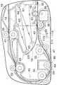
次に図3を参照して、原稿ガイド13について説明する。図3はスキャナフレーム12及び原稿ガイド13の様子を示した拡大断面図である。 Next, the
原稿ガイド13は前述のとおり第1原稿読取位置80の下流側に配置されるとともに、フレーム面14の下方に配置されている。更に、原稿ガイド13は、湾曲状の原稿搬送経路30に下側から接するようにして、当該原稿搬送経路30の外側に配置されている。また、この原稿ガイド13は、湾曲部(第1案内部)71と、直線部(第2案内部)72と、を備えている。 As described above, the
湾曲部71は、第1原稿読取位置80の下流側近傍から開始される曲面状の斜面を有するように形成される。この斜面は、第1原稿読取位置80から第2原稿読取位置90に近づくに従って、原稿搬送経路30に沿ってせり上がるような形状に構成されている。これにより、前記湾曲部71は、その高さが前記第2スキャナユニット60の読取ガラス42の高さ近傍まで上昇するように構成されることになる。また、この湾曲部71の中途部には、搬送ローラ35に対向するように対向ローラ(回転ローラ)47が配置されている。 The
湾曲部71の下流側には、前記直線部72が接続される。この直線部72は、原稿搬送方向下流側に水平方向に延びる平面を有している。直線部72の下流側端部にはプラテンローラ38が配置されており、前記読取ガラス42に、直線部72の下流側端部(プラテンローラ38)が対面する状態となっている。 The
そして、図4に示すように、前記湾曲部71と前記フレーム面14が第2原稿読取位置90の上流側で合流し、この合流地点から前記直線部72が第2原稿読取位置90に向かって延びるように構成されている。具体的にいえば、原稿ガイド13とフレーム面14は上下方向でほぼ対応する位置に配置されており、第2原稿読取位置90に近づくに従って原稿ガイド13とフレーム面14との間隔が狭まるような形状となっている。そして、更に第2原稿読取位置90に近づいていくと、フレーム面14が原稿搬送経路30と合流するとともに、その合流位置から水平状の直線部72が原稿搬送経路30に沿って延びるように構成されている。 Then, as shown in FIG. 4, the
即ち、前記湾曲部71が前記直線部72に移行する位置と、フレーム面14が原稿ガイド13の案内面(原稿搬送経路30)に合流する位置とが、ほぼ一致するように構成されている。言い換えれば、前記湾曲部71、前記直線部72及び前記フレーム面14が、正面視において横向きY字状になるように接続されている。 That is, the position where the
この構成で、第1原稿読取位置80で表側の面の画像が読み取られた原稿は、原稿ガイド13の湾曲部71へ送られる。湾曲部71へ搬送された原稿は、当該湾曲部71に配置される搬送ローラ35と対向ローラ47によって、更に下流側の直線部72に搬送される。そして原稿は、スキャナフレーム12(フレーム面14)と原稿ガイド13の間に形成される原稿搬送経路30に従って、第2原稿読取位置90まで搬送される。原稿は、第2原稿読取位置90で裏側の面の画像を読み取られた後、排出ローラ36まで搬送され、排出トレイ24へ排出される。 With this configuration, the document whose front side image is read at the first
次に、ヒンジ機構46によるスキャナフレーム12のスキャナフレーム12の開閉について説明する。図4はスキャナフレーム12の開閉の様子を示した要部断面図である。 Next, opening and closing of the
前記スキャナフレーム12は、通常の状態では図2に示すように原稿搬送経路30の内側に位置しており、ほぼ水平姿勢となっている。そして、第2スキャナユニット60のメンテナンス等を行う際には、最初に、ADF25のカバー部11を持ち上げるように上方向に回動させて、図4に示すようにカバー部11を開いた状態とする。これにより、レジストローラ39及び分離ローラ32のニップが解除されるとともに、原稿搬送経路30の上流側半部が開放される。 In a normal state, the
次に、スキャナフレーム12を持ち上げることで、図4の実線で描かれた位置(使用位置)から前記ローラ軸41を中心に回動させて上方向に引き出し、図4の鎖線で示す位置(露出位置)まで移動させる。これにより、第2スキャナユニット60の読取ガラス42を露出させ、清掃等のメンテナンス作業を容易に行うことができる。 Next, by lifting the
なお、前記スキャナフレーム12は、前述のとおり、折返し部45に近づくに従って原稿搬送経路30から徐々に離れるように形成されたフレーム面14を有している。また、前記原稿ガイド13の湾曲部71及び直線部72と、フレーム面14とがY字状に接続するように構成されている。これにより、スキャナフレーム12の回動時にフレーム面14と原稿ガイド13が干渉することを回避でき、スキャナフレーム12をスムーズに開放させることができる。 As described above, the
メンテナンス作業等の終了後、図2等に示す使用位置に戻すために、ユーザはスキャナフレーム12を手で押し下げる。スキャナフレーム12は、前述のローラ軸41を中心に下方向に回動する。その後、更にカバー部11を閉じることで、ADF25を再び使用できる状態になる。 After the maintenance work is completed, the user pushes the
以上に示すように、本実施形態の複合機20が備えるイメージスキャナ装置10は、レジストローラ39と、第1スキャナユニット50と、縮小光学系の第2スキャナユニット60と、スキャナフレーム12と、原稿ガイド13と、を備える。前記レジストローラ39は、折返し部45を有するU字状の原稿搬送経路30に配置される。第1スキャナユニット50は、原稿搬送経路30に沿って搬送される原稿の表側の面を読み取るために前記原稿搬送経路30の外側に配置される。第2スキャナユニット60は、原稿の裏側の面を読み取るために原稿搬送経路30の内側に配置される。前記スキャナフレーム12は、前記レジストローラ39の軸線を回動中心として、前記原稿を読み取るときの使用位置から前記第2スキャナユニット60の読取ガラス42が露出する露出位置に回動可能である。また、スキャナフレーム12の前記レジストローラ39より前記折返し部45に近い側の部分に、前記第2スキャナユニット60が有する光路の一部が配置される。原稿ガイド13は、前記第1スキャナユニット50のコンタクトガラス44から前記第2スキャナユニット60の読取ガラス42へ原稿搬送経路30に従って前記原稿をガイドする。また、この原稿ガイド13は、湾曲部71と、直線部72と、を備える。湾曲部71は、原稿搬送経路30の下流側へ行くに従って、前記第2スキャナユニット60の読取ガラス42が配置されている高さ近傍まで上昇するように形成される。前記直線部72は、前記湾曲部71の下流側に配置され、その向きを前記湾曲部71よりも水平に近づけながら(水平向きに変えながら)下流側へと延びるように形成される。 As described above, the
この構成により、第2スキャナユニット60を保持するスキャナフレーム12を原稿搬送経路30の内側(折返し部45に近い側)に差し込むように配置することができ、イメージスキャナ装置10内のスペースを有効に活用することができる。また、原稿ガイド13の直線部72は湾曲部71よりも向きを水平に近づけるように形成されているので、第2スキャナユニット60まで原稿ガイド13が直線で形成される場合に比べて、イメージスキャナ装置10内の高さ方向のスペースを有効に使うことができる。更に、スキャナフレーム12の回動中心がレジストローラ39と同軸上にあるので、構成を簡素化することができ、製造コスト及び製造工数を低減することができる。 With this configuration, the
また、本実施形態のイメージスキャナ装置10において、前記スキャナフレーム12は、第2スキャナユニット60の読取ガラス42から折返し部45に近い側の一部において、当該折返し部45に近づくに従って前記原稿搬送経路30から離れるようなフレーム面14を有している。また、前記湾曲部71は湾曲状に構成されている。そして、前記フレーム面14、前記湾曲部71及び直線部72がY字状に接続される。 Further, in the
この構成により、Y字の合流地点まではフレーム面14及び湾曲部71の湾曲部分が互いに離れているので、スキャナフレーム12の回動時に原稿ガイド13に干渉することなくスキャナフレーム12を露出位置まで回動させることができる。また、湾曲部71が湾曲しながら上昇しているので、原稿の引っ掛かりを防止しながらスムーズに原稿を上昇させて下流側へ搬送することができる。 With this configuration, since the curved portion of the
また、本実施形態のイメージスキャナ装置10においては、前記直線部72が水平な直線状に形成される。 Further, in the
この構成により、イメージスキャナ装置10内の高さ方向のスペースを更に有効に利用できるので、原稿読取装置を特に高さ方向で一層コンパクトに構成することができる。 With this configuration, since the space in the height direction in the
また、本実施形態のイメージスキャナ装置10においては、前記直線部72に対面するように前記読取ガラス42が位置する。 Further, in the
この構成により、原稿を水平方向に搬送しながら第2スキャナユニット60で読み取る形になるので、原稿を安定的かつ正確に読み取ることができる。 With this configuration, since the original is read by the
また、本実施形態のイメージスキャナ装置10においては、前記湾曲部71に対向ローラ47が配置される。 Further, in the
この構成により、第1原稿読取位置80から搬送されてきた原稿を、対向ローラ47によって確実に下流側へ導くことができる。また、対向ローラ47は湾曲部71に配置されるので、対向ローラ47を他の構成の邪魔になることなく合理的に配置できる。 With this configuration, the document conveyed from the first
なお、上記実施形態では原稿ガイド13に湾曲部71が形成されているが、図5に示すように、この湾曲部71に代えて直線状の斜面を形成し、原稿ガイド13が2つの直線部を有するように変更することができる。以下、この変形例について図5を参照して説明する。なお、この変形例においては、上記実施形態と同一及び類似する構成について、図面に同一の符号を付して説明を省略する場合がある。 In the above embodiment, the
図5に示すように、変形例の原稿ガイド113は、傾斜部171と、直線部172と、傾斜部171及び直線部172とを接続する屈曲部173と、を備える。傾斜部171は、第1原稿読取位置80の下流側の近傍から第2原稿読取位置90の高さまで直線的に上昇するように形成されている。一方、屈曲部173を挟んで傾斜部171の下流側に配置される直線部172は、第2原稿読取位置90まで水平な向きに延びている。この構成によっても、ADF25内(イメージスキャナ装置10内)の高さ方向のスペースを有効に使うことができる。また、傾斜部171が平面的に構成されているので、原稿ガイド113の形状を単純化でき、製造コストを低減することができる。 As shown in FIG. 5, the
以上に本発明の好適な実施形態を説明したが、上記の構成は更に以下のように変更することができる。 Although the preferred embodiment of the present invention has been described above, the above configuration can be further modified as follows.
上記実施形態の湾曲部71に代えて、例えば、上方に傾斜する直線部分と湾曲部分とを組み合わせた形状に変更することができる。また、直線部72の部分が湾曲状となるように変更したり、直線部72が水平ではなく若干の傾斜を有する直線状となるように変更することもできる。 Instead of the bending
また、上記実施形態では、湾曲部71に配置される対向ローラ47は、搬送ローラ35の駆動に伴って従動回転するように構成されている。しかしながらこの構成に代えて、駆動側のローラを湾曲部71(原稿ガイド13)に配置する構成に変更することができる。 Further, in the above-described embodiment, the facing
前記コピーファクシミリ複合機20に代えて、例えば、コピー機、ファクシミリ装置等にも、本発明のイメージスキャナ装置10を適用することができる。 For example, the
上記実施形態ではイメージスキャナ装置10は複合機20の一部として備えられているが、この構成に代えて、単体のイメージスキャナ装置として構成することができる。 In the above embodiment, the
10 イメージスキャナ装置(原稿読取装置)
12 スキャナフレーム
13 原稿ガイド
14 フレーム面
20 コピーファクシミリ複合機
25 自動原稿搬送装置(ADF)
30 原稿搬送経路
39 レジストローラ
42 読取ガラス(第2の読取部の読取部分)
44 コンタクトガラス(第1の読取部の読取部分)
50 第1スキャナユニット(第1の読取部)
60 第2スキャナユニット(第2の読取部)
71 湾曲部(第1案内部)
72 直線部(第2案内部)10 Image scanner device (document reading device)
12
30
44 Contact glass (reading part of the first reading unit)
50 First scanner unit (first reading unit)
60 Second scanner unit (second reading unit)
71 Curved part (first guide part)
72 Straight part (second guide part)
Claims (5)
Translated fromJapanese前記原稿搬送経路に沿って搬送される前記原稿の第1面を読み取るために前記原稿搬送経路の外側に配置される第1の読取部と、
前記原稿の第2面を読み取るために前記原稿搬送経路の内側に配置される縮小光学系の第2の読取部と、
前記ローラの軸線を回動中心として、前記原稿を読み取るときの使用位置から前記第2の読取部の読取部分が露出する露出位置に回動可能であるとともに、前記ローラより前記折返し部に近い側に、前記第2の読取部が有する光路を構成する反射ミラーが配置されるスキャナフレームと、
前記第1の読取部の読取部分から前記第2の読取部の読取部分へ前記原稿搬送経路に従って前記原稿をガイドする原稿ガイドと、
を備え、
前記第2の読取部は、前記スキャナフレームの内部に配置されており、
前記原稿ガイドは、
前記原稿搬送経路の下流側へ行くに従って、前記第2の読取部の読取部分が配置されている高さ近傍まで上昇するように形成される第1案内部と、
前記第1案内部の下流側に配置され、その向きを前記第1案内部よりも水平に近づけながら下流側へと延びるように形成される第2案内部と、
を備えることを特徴とする原稿読取装置。A roller disposed in a U-shaped document conveyance path having a folded portion;
A first reading unit disposed outside the document conveyance path for reading a first surface of the document conveyed along the document conveyance path;
A second reading unit of a reduction optical system disposed inside the document transport path for reading the second surface of the document;
With the axis of the roller as the rotation center, the roller can be rotated from the use position when reading the document to the exposed position where the reading portion of the second reading unit is exposed, and closer to the folding portion than the roller A scanner frame on whicha reflection mirror constituting the optical pathof the second reading unit is disposed;
A document guide for guiding the document along the document transport path from a reading portion of the first reading unit to a reading portion of the second reading unit;
With
The second reading unit is disposed inside the scanner frame,
The document guide is
A first guide portion formed so as to rise to a vicinity of a height at which a reading portion of the second reading portion is arranged as it goes downstream of the document conveyance path;
A second guide part disposed on the downstream side of the first guide part and formed to extend to the downstream side while approaching the horizontal direction of the first guide part;
An original reading apparatus comprising:
前記スキャナフレームは、前記第2の読取部の読取部分から前記折返し部に近い側の少なくとも一部において、当該折返し部に近づくに従って前記原稿搬送経路から離れるようなフレーム面を有しており、
前記第1案内部は湾曲状に構成されており、
前記フレーム面、前記第1案内部及び前記第2案内部がY字状に接続されることを特徴とする原稿読取装置。The document reading device according to claim 1,
The scanner frame has a frame surface such that at least a part of the second reading unit on the side close to the folding unit is separated from the document conveyance path as the folding unit is approached.
The first guide portion is configured in a curved shape,
The document reading apparatus, wherein the frame surface, the first guide portion, and the second guide portion are connected in a Y shape.
前記第2案内部が水平な直線状に形成されることを特徴とする原稿読取装置。The document reading device according to claim 2,
The document reading apparatus, wherein the second guide portion is formed in a horizontal linear shape.
前記第2案内部に対面するように前記第2の読取部の読取部分が位置することを特徴とする原稿読取装置。The document reading device according to claim 3,
A document reading apparatus, wherein a reading portion of the second reading unit is positioned so as to face the second guide unit.
前記第1案内部に回転ローラが配置されることを特徴とする原稿読取装置。The document reading device according to any one of claims 1 to 4,
A document reading apparatus, wherein a rotation roller is disposed in the first guide portion.
Priority Applications (1)
| Application Number | Priority Date | Filing Date | Title |
|---|---|---|---|
| JP2008104699AJP4596033B2 (en) | 2008-04-14 | 2008-04-14 | Document reader |
Applications Claiming Priority (1)
| Application Number | Priority Date | Filing Date | Title |
|---|---|---|---|
| JP2008104699AJP4596033B2 (en) | 2008-04-14 | 2008-04-14 | Document reader |
Publications (2)
| Publication Number | Publication Date |
|---|---|
| JP2009260477A JP2009260477A (en) | 2009-11-05 |
| JP4596033B2true JP4596033B2 (en) | 2010-12-08 |
Family
ID=41387368
Family Applications (1)
| Application Number | Title | Priority Date | Filing Date |
|---|---|---|---|
| JP2008104699AExpired - Fee RelatedJP4596033B2 (en) | 2008-04-14 | 2008-04-14 | Document reader |
Country Status (1)
| Country | Link |
|---|---|
| JP (1) | JP4596033B2 (en) |
Families Citing this family (2)
| Publication number | Priority date | Publication date | Assignee | Title |
|---|---|---|---|---|
| JP7166826B2 (en)* | 2018-07-30 | 2022-11-08 | キヤノン株式会社 | Image reading device and image forming device |
| JP7718869B2 (en)* | 2021-06-25 | 2025-08-05 | キヤノン株式会社 | Image reading device and image forming device |
Family Cites Families (11)
| Publication number | Priority date | Publication date | Assignee | Title |
|---|---|---|---|---|
| JPH0715645U (en)* | 1993-08-30 | 1995-03-17 | 村田機械株式会社 | Paper feeder |
| JP2928449B2 (en)* | 1993-12-27 | 1999-08-03 | 株式会社ピーエフユー | Image reading device |
| JPH09214673A (en)* | 1996-01-31 | 1997-08-15 | Ricoh Co Ltd | Image reading device |
| JP3420883B2 (en)* | 1996-04-17 | 2003-06-30 | 株式会社リコー | Double-sided document reader |
| JP3571288B2 (en)* | 2000-11-13 | 2004-09-29 | ニスカ株式会社 | Automatic document feeder having image reading means and image reading apparatus |
| JP2002344695A (en)* | 2001-05-15 | 2002-11-29 | Canon Inc | Image reading device |
| JP2004099240A (en)* | 2002-09-10 | 2004-04-02 | Murata Mach Ltd | Image reader |
| JP2005167851A (en)* | 2003-12-04 | 2005-06-23 | Murata Mach Ltd | Image reading apparatus |
| JP2005167817A (en)* | 2003-12-04 | 2005-06-23 | Murata Mach Ltd | Image reading apparatus |
| JP2006036410A (en)* | 2004-07-23 | 2006-02-09 | Kyocera Mita Corp | Automatic manuscript reading device |
| JP2007096662A (en)* | 2005-09-28 | 2007-04-12 | Sharp Corp | Image reading apparatus and image processing apparatus |
- 2008
- 2008-04-14JPJP2008104699Apatent/JP4596033B2/ennot_activeExpired - Fee Related
Also Published As
| Publication number | Publication date |
|---|---|
| JP2009260477A (en) | 2009-11-05 |
Similar Documents
| Publication | Publication Date | Title |
|---|---|---|
| JP5522368B2 (en) | Automatic document feeder and document reader | |
| JP6040714B2 (en) | Automatic document conveying device, image reading device equipped with automatic document conveying device, and image forming apparatus | |
| JP2017224892A (en) | Image reading apparatus and image forming apparatus | |
| JP2007067605A (en) | Image reading device | |
| JP4259325B2 (en) | Automatic document feeder | |
| JP4596033B2 (en) | Document reader | |
| JP4331668B2 (en) | Document reader | |
| JP3747879B2 (en) | Image reading device | |
| JP4095054B2 (en) | Document reader | |
| JP2004099240A (en) | Image reader | |
| JP4165541B2 (en) | Automatic document feeder and image reading apparatus | |
| KR101430017B1 (en) | Auto document feeding apparatus and document reading device including the same | |
| JP4207943B2 (en) | Automatic document feeder and image reading apparatus | |
| JP4941677B2 (en) | Automatic document feeder and document reader having the same | |
| JP2017224893A (en) | Image reading apparatus and image forming apparatus | |
| JP5024677B2 (en) | Automatic document feeder and document reader | |
| JP5556344B2 (en) | Automatic document feeder and image forming apparatus having the same | |
| JP3922254B2 (en) | Image reading device | |
| JP5146914B2 (en) | Automatic document feeder and document reader having the same | |
| JPH11205536A (en) | Image reader | |
| JP5545535B2 (en) | Automatic document feeder and document reader having the same | |
| JP2006273535A (en) | Image reading apparatus | |
| JP4666287B2 (en) | Automatic document feeder and document reader | |
| JP3906839B2 (en) | Automatic document feeder | |
| JP2014003547A (en) | Image reader and image formation apparatus |
Legal Events
| Date | Code | Title | Description |
|---|---|---|---|
| A977 | Report on retrieval | Free format text:JAPANESE INTERMEDIATE CODE: A971007 Effective date:20100427 | |
| A131 | Notification of reasons for refusal | Free format text:JAPANESE INTERMEDIATE CODE: A131 Effective date:20100608 | |
| A521 | Request for written amendment filed | Free format text:JAPANESE INTERMEDIATE CODE: A523 Effective date:20100722 | |
| TRDD | Decision of grant or rejection written | ||
| A01 | Written decision to grant a patent or to grant a registration (utility model) | Free format text:JAPANESE INTERMEDIATE CODE: A01 Effective date:20100824 | |
| A01 | Written decision to grant a patent or to grant a registration (utility model) | Free format text:JAPANESE INTERMEDIATE CODE: A01 | |
| A61 | First payment of annual fees (during grant procedure) | Free format text:JAPANESE INTERMEDIATE CODE: A61 Effective date:20100906 | |
| R150 | Certificate of patent or registration of utility model | Ref document number:4596033 Country of ref document:JP Free format text:JAPANESE INTERMEDIATE CODE: R150 Free format text:JAPANESE INTERMEDIATE CODE: R150 | |
| FPAY | Renewal fee payment (event date is renewal date of database) | Free format text:PAYMENT UNTIL: 20131001 Year of fee payment:3 | |
| FPAY | Renewal fee payment (event date is renewal date of database) | Free format text:PAYMENT UNTIL: 20131001 Year of fee payment:3 | |
| FPAY | Renewal fee payment (event date is renewal date of database) | Free format text:PAYMENT UNTIL: 20141001 Year of fee payment:4 | |
| R250 | Receipt of annual fees | Free format text:JAPANESE INTERMEDIATE CODE: R250 | |
| R250 | Receipt of annual fees | Free format text:JAPANESE INTERMEDIATE CODE: R250 | |
| R250 | Receipt of annual fees | Free format text:JAPANESE INTERMEDIATE CODE: R250 | |
| R250 | Receipt of annual fees | Free format text:JAPANESE INTERMEDIATE CODE: R250 | |
| R250 | Receipt of annual fees | Free format text:JAPANESE INTERMEDIATE CODE: R250 | |
| R250 | Receipt of annual fees | Free format text:JAPANESE INTERMEDIATE CODE: R250 | |
| R250 | Receipt of annual fees | Free format text:JAPANESE INTERMEDIATE CODE: R250 | |
| R250 | Receipt of annual fees | Free format text:JAPANESE INTERMEDIATE CODE: R250 | |
| R250 | Receipt of annual fees | Free format text:JAPANESE INTERMEDIATE CODE: R250 | |
| R250 | Receipt of annual fees | Free format text:JAPANESE INTERMEDIATE CODE: R250 | |
| LAPS | Cancellation because of no payment of annual fees |