JP4594509B2 - Stem screw assembly - Google Patents
Stem screw assemblyDownload PDFInfo
- Publication number
- JP4594509B2 JP4594509B2JP2000308713AJP2000308713AJP4594509B2JP 4594509 B2JP4594509 B2JP 4594509B2JP 2000308713 AJP2000308713 AJP 2000308713AJP 2000308713 AJP2000308713 AJP 2000308713AJP 4594509 B2JP4594509 B2JP 4594509B2
- Authority
- JP
- Japan
- Prior art keywords
- insert
- head
- fastener
- screw assembly
- recess
- Prior art date
- Legal status (The legal status is an assumption and is not a legal conclusion. Google has not performed a legal analysis and makes no representation as to the accuracy of the status listed.)
- Expired - Fee Related
Links
Images


Classifications
- A—HUMAN NECESSITIES
- A61—MEDICAL OR VETERINARY SCIENCE; HYGIENE
- A61B—DIAGNOSIS; SURGERY; IDENTIFICATION
- A61B17/00—Surgical instruments, devices or methods
- A61B17/56—Surgical instruments or methods for treatment of bones or joints; Devices specially adapted therefor
- A61B17/58—Surgical instruments or methods for treatment of bones or joints; Devices specially adapted therefor for osteosynthesis, e.g. bone plates, screws or setting implements
- A61B17/68—Internal fixation devices, including fasteners and spinal fixators, even if a part thereof projects from the skin
- A61B17/70—Spinal positioners or stabilisers, e.g. stabilisers comprising fluid filler in an implant
- A61B17/7001—Screws or hooks combined with longitudinal elements which do not contact vertebrae
- A61B17/7035—Screws or hooks, wherein a rod-clamping part and a bone-anchoring part can pivot relative to each other
- A61B17/7037—Screws or hooks, wherein a rod-clamping part and a bone-anchoring part can pivot relative to each other wherein pivoting is blocked when the rod is clamped
- A—HUMAN NECESSITIES
- A61—MEDICAL OR VETERINARY SCIENCE; HYGIENE
- A61B—DIAGNOSIS; SURGERY; IDENTIFICATION
- A61B17/00—Surgical instruments, devices or methods
- A61B17/56—Surgical instruments or methods for treatment of bones or joints; Devices specially adapted therefor
- A61B17/58—Surgical instruments or methods for treatment of bones or joints; Devices specially adapted therefor for osteosynthesis, e.g. bone plates, screws or setting implements
- A61B17/68—Internal fixation devices, including fasteners and spinal fixators, even if a part thereof projects from the skin
- A61B17/70—Spinal positioners or stabilisers, e.g. stabilisers comprising fluid filler in an implant
- A61B17/7074—Tools specially adapted for spinal fixation operations other than for bone removal or filler handling
- A61B17/7076—Tools specially adapted for spinal fixation operations other than for bone removal or filler handling for driving, positioning or assembling spinal clamps or bone anchors specially adapted for spinal fixation
- A61B17/7082—Tools specially adapted for spinal fixation operations other than for bone removal or filler handling for driving, positioning or assembling spinal clamps or bone anchors specially adapted for spinal fixation for driving, i.e. rotating, screws or screw parts specially adapted for spinal fixation, e.g. for driving polyaxial or tulip-headed screws
- A—HUMAN NECESSITIES
- A61—MEDICAL OR VETERINARY SCIENCE; HYGIENE
- A61B—DIAGNOSIS; SURGERY; IDENTIFICATION
- A61B17/00—Surgical instruments, devices or methods
- A61B17/56—Surgical instruments or methods for treatment of bones or joints; Devices specially adapted therefor
- A61B17/58—Surgical instruments or methods for treatment of bones or joints; Devices specially adapted therefor for osteosynthesis, e.g. bone plates, screws or setting implements
- A61B17/68—Internal fixation devices, including fasteners and spinal fixators, even if a part thereof projects from the skin
- A61B17/70—Spinal positioners or stabilisers, e.g. stabilisers comprising fluid filler in an implant
- A61B17/7001—Screws or hooks combined with longitudinal elements which do not contact vertebrae
- A61B17/7032—Screws or hooks with U-shaped head or back through which longitudinal rods pass
- A—HUMAN NECESSITIES
- A61—MEDICAL OR VETERINARY SCIENCE; HYGIENE
- A61B—DIAGNOSIS; SURGERY; IDENTIFICATION
- A61B17/00—Surgical instruments, devices or methods
- A61B17/56—Surgical instruments or methods for treatment of bones or joints; Devices specially adapted therefor
- A61B17/58—Surgical instruments or methods for treatment of bones or joints; Devices specially adapted therefor for osteosynthesis, e.g. bone plates, screws or setting implements
- A61B17/68—Internal fixation devices, including fasteners and spinal fixators, even if a part thereof projects from the skin
- A61B17/84—Fasteners therefor or fasteners being internal fixation devices
- A61B17/86—Pins or screws or threaded wires; nuts therefor
- A61B17/8605—Heads, i.e. proximal ends projecting from bone
- A61B17/861—Heads, i.e. proximal ends projecting from bone specially shaped for gripping driver
Landscapes
- Health & Medical Sciences (AREA)
- Orthopedic Medicine & Surgery (AREA)
- Neurology (AREA)
- Life Sciences & Earth Sciences (AREA)
- Surgery (AREA)
- Heart & Thoracic Surgery (AREA)
- Engineering & Computer Science (AREA)
- Biomedical Technology (AREA)
- Nuclear Medicine, Radiotherapy & Molecular Imaging (AREA)
- Medical Informatics (AREA)
- Molecular Biology (AREA)
- Animal Behavior & Ethology (AREA)
- General Health & Medical Sciences (AREA)
- Public Health (AREA)
- Veterinary Medicine (AREA)
- Surgical Instruments (AREA)
- Mutual Connection Of Rods And Tubes (AREA)
Description
Translated fromJapanese【0001】
【発明の属する技術分野】
本発明は、脊椎固定装置に関し、特に、拡張可能な頭部付き茎用ねじを有する茎用ねじアセンブリに関するものである。好適な実施例において、この茎用ねじアセンブリは、座部を有する継手要素を含んでいて、該座部が茎用ねじの頭部を受けると共に、継手要素に関する茎用ねじの多軸線回りの運動を可能にしており、また、同茎用ねじアセンブリは、継手要素及び茎用ねじが相対的に運動するのを阻止するように、茎用ねじの頭部を拡開して継手要素の座部に押し付けるインサートを含んでいる。
【0002】
【従来の技術】
脊柱は、骨及び結合組織からなる非常に複雑な系統であり、この系統が身体の支持を可能にすると共に、精緻な脊柱及び諸神経を保護している。該脊柱は、1つの上にもう1つが積み重ねられた一連の椎骨を含んでおり、ここで、その各椎体は、椎体の外側面(皮質)を形成する比較的に強固な骨部分と、椎体の中心部(海綿状)を形成する比較的に弱い骨部分とを含んでいる。各椎体間には椎間板があり、これは、脊柱に加えられる圧縮力の緩衝及び抑制に備えている。精緻な脊髄及び諸神経を含む脊柱管は、椎体の後部に位置している。
【0003】
種々の脊柱疾患が知られており、該疾患には、側湾症(脊椎の異常な側方湾曲),後湾症(通常は胸椎における脊椎の異常な前方湾曲),過剰前湾症(通常は腰椎における脊椎の異常な後方湾曲),脊椎すべり症(通常は腰椎もしくは頚椎における1つの椎骨上での別の椎骨の前転位),及びその他の疾患がある。その他の疾患は、椎間板の割れ又はずれ、変形性椎間板症、椎骨の骨折等のような異常,疾患もしくは障害により生じる。このような病気で苦しむ患者は、通常、神経機能の低下に加えて、極端な衰弱性の痛みを経験する。
【0004】
本発明は、外科用移植材料を用いて脊椎の隣接椎骨を一緒に融着及び/又は機械的に固定する、脊椎固定と通常言われている技術にかかわっている。脊椎固定はまた、脊椎の全体的なアラインメントを変更するように隣接椎骨の互いのアラインメントを変更するのにも使用される。かかる技術は、上述した病気を治療するために、そして、大抵の場合、患者が受けている痛みを和らげるために、効果的に使用されてきた。しかしながら、後から詳しく述べるように、現在の固定装置に関しては幾つかの欠点がある。
【0005】
ある脊椎固定技術は、脊椎とほぼ平行に延びる、脊椎ロッドと通常言われる整形ロッドを使用することにより脊椎を固定することを含んでいる。これは、脊椎を後方から露出させると共に、骨用ねじを適切な椎骨の茎(pedicles)に固定することにより行われる。該茎用ねじ(pedicle screw)は、通常、1つの椎骨につき2つ、即ち、棘突起の両側にある各茎のところに1つ設けられ、脊椎ロッドの固定ポイントとして作用する。その後、脊椎ロッドを受けるようになっているクランプ要素が使用され、脊椎ロッドを茎用ねじに結合する。この脊椎ロッドの調整影響力により、脊椎は、もっと望ましい形状に倣うように力を受ける。ある例においては、脊椎ロッドは、望ましい湾曲の脊柱を実現するために曲がることがある。
【0006】
ビナウド(Vignaud)等に対する米国特許第5,129,388号明細書は、U形状の頭部が剛に接続された茎用ねじを含む脊椎固定装置を開示している。このU形状の頭部は、その内部に脊椎ロッドを受けるためU形状のチャンネルを含んでいる。U形状の頭部には雌ねじ部が設けられているので、雄ねじ部を有する止めねじを雌ねじ部にねじ込みうる。茎用ねじを骨に挿入し、そして脊椎ロッドをU形状のチャンネルに配置した後、止めねじを継手要素の雌ねじ部にねじ込んで、脊椎ロッドをU形状のチャンネル内に固定すると共に、同脊椎ロッド及び茎用ねじ間の相対運動を防止する。また、該脊椎固定装置は、U形状の要素の上方部を覆うキャップを含んでいて、止めねじをU形状の頭部にねじ込む際にU形状の要素のアームが広がるのを防止している。
【0007】
【発明が解決しようとする課題】
外科医は、上述した米国特許第5,129,388号明細書に開示されたような脊椎固定装置を挿入しようと試みる際に、かなりの難しさをしばしば経験してきた。例えば、外科医は、往々にして、脊椎ロッドを骨用ねじのU形状頭部の中に効率的且つ適切に入れることができなかった。これは、脊椎の湾曲と、ねじが設けられる茎の配向が異なるため、茎用ねじのU形状の頭部が互いに整列しないことが往々にしてあるからである。脊椎ロッドは、茎用ねじを脊椎ロッドに接続するために、複数の平面上で曲げられることがしばしばあり、これは、脊椎ロッドとの結合を弱くすることになる。また、これらの諸問題は、手術を相当に長引かせることになり、外科手術に関連した合併症の可能性を増すことになる。
【0008】
上述した米国特許第5,129,388号明細書において認められた諸問題に応えて、エリコ(Errico)等に対する米国特許第5,733,286号, ビーダーマン(Biedermann)等に対する米国特許第5,672,176号及びメッツ−スタベンハーゲン(Metz-Stavenhagen)に対する米国特許第5,476,464号の各明細書は、骨に固定された固定要素が球状の頭部を有している多軸の脊椎固定装置を開示している。これらの米国特許における脊椎固定装置は、整形ロッド捕捉アセンブリを有していて、整形ロッドを該捕捉アセンブリ内に取り付けると共に、該整形ロッドを固定要素に接続する。固定要素の球状の頭部は、該固定要素が整形ロッドの捕捉アセンブリに関して運動することを可能にする。しかし、上述した米国特許のものは、各脊椎固定装置が挿入後にずれるかも知れないので、米国特許第5,129,388号明細書に記載のものに認められる欠点の全てを解消するものではない。これは主として、固定要素の球状の頭部と整形ロッド捕捉アセンブリとの間の表面接触面積が不十分であることに由来している。また、該脊椎固定装置は複雑であり製造が難しい。
【0009】
他の多軸骨固定装置は、国際特許公報WO88/03781号に教示されている。この公報は、骨結合板にある開口に骨用ねじを固定するための装置を記載している。骨用ねじの頭部は長手方向の溝を備えていて、この溝により、骨結合板にある開口の1つに入れられた後、頭部を拡張可能としている。ねじを開口の1つに挿通した後、頭部を拡開するために該頭部の頂部にある孔に調整ねじを螺入する。拡開した頭部の外表面は、骨結合板にねじを固定するように、骨結合板にある開口に圧接する。米国特許第4,484,570号明細書もまた骨結合板と関連して用いられる骨用ねじを開示しており、該骨用ねじは、中央の開口と複数のスロットをもつ頭部を有していて、該開口及びスロットが頭部を複数の舌状部に分割している。頭部にある中央の開口には、頭部を拡開すると共に骨用ねじを骨結合板に関してロックするために、円錐面を有する拡開工具が挿入される。しかし、国際特許公報WO88/03781号及び米国特許第4,484,570号明細書に記載のものは骨板に関係しており、整形ロッドを用いる脊椎固定装置ではない。
【0010】
上述した装置があるにもかかわらず、先行技術の脊椎固定装置は、ねじ頭部のロック方法,使用法の複雑さ,整形ロッド及びロッド捕捉アセンブリの適正配置の難しさ,幾つかの複雑な装置に関連した多数のパーツに必要な操作,並びに2種間の弱い境界面に由来する骨固定装置に関するロッド捕捉アセンブリの術後移動等において改良の余地がある。
【0011】
【課題を解決するための手段】
本発明に係る茎用ねじアセンブリは上記課題を解決すべく以下のように構成されている。茎用ねじアセンブリは、骨に挿入するための先端部と、該先端部の反対側端部のところにある拡張可能な頭部とを有する締結具を含んでいる。該頭部は、それを形成している材料により、或いはその構造により拡張可能としうる。拡張可能な頭部についての好適な一構造は、1つ以上のスロットが形成された頭部を含んでいる。この場合において、拡張可能な頭部は、凸状部を含む外表面と、内法寸法を有する内表面を規定する凹所と、頭部の拡張を可能にするため内表面及び外表面間に延在する少なくとも1つのスロットを有するのが好ましい。また、該茎用ねじアセンブリは、頭部の凹所内に少なくとも部分的に配置することができるインサートを含んでいる。このインサートは、上述した凹所の内法寸法よりも大きい外法寸法を含む外表面を有する。この場合においては、インサートは頭部の凹所と一緒に回転可能でよい。
【0012】
また、茎用ねじアセンブリは、茎用ねじを整形ロッドに結合するための継手要素を含んでいる。該継手要素は、締結具を受け入れるため同継手要素を貫いて延びる孔と、締結具の頭部を受ける座部とを有するのが好ましい。座部は、頭部の凸状部を受けると共に、更なる枢回運動を阻止するためロックされる前に締結具及び継手要素が相対的に枢回するのを可能にする凹状部を含んでいてよい。茎用ねじアセンブリは更に、継手要素に関連したロック部材を含んでいてよい。このロック部材は、整形ロッドが継手要素内に配置された後、該整形ロッドを継手要素内にロックする。該ロック部材は、インサートの外法寸法が頭部の内法寸法に当接するように、インサートを頭部の凹所内に押し込むようになっているのが望ましく、継手要素が締結具に関して更に枢回運動するのを阻止するため頭部が拡開して継手要素の座部に当る。
【0013】
締結具の拡張可能な頭部は、改良されたレベルの表面接触を頭部と継手要素の座部の間に与えるのに備えている。この表面接触レベルの向上は、より確実なロック力を発生させる結果になる。また、ロック力は、締結具の頭部及び継手要素間の境界面のところで作用する摩擦力により増大する。この摩擦力は、継手要素の座部上にある締結具の頭部の法線力に比例し、従って、インサートが締結具の頭部を拡開させるべく作用するにつれて増大する。その結果、1つ以上の骨締結具に関する脊椎ロッド又は継手要素の術後のずれ及び/又は移動の可能性が相当に減少する。更に、本発明の茎用ねじアセンブリは部品の数が少ない。その結果、移植手術が非常に簡略化されると共に、構成要素が患者の身体内に落下する可能性が大きく減少する。
【0014】
好適には、締結具は、ねじの先端部から頭部に向かい延びる雄ねじ部を有する茎用骨ねじ(pedicle bone screw)である。締結具は、サッタ−(Sutter)の米国特許第4,484,570号明細書に開示されたような骨移植片材料を受けるため雄ねじ部にある1つ以上の穴を有していてよい。ねじを骨に固定するためにねじを使用する代わりに、他の好適な場合において、締結具は、前述したメッツ−スタベンハーゲンに対する米国特許第5,476,464号明細書に開示されたようなフック形状の固定要素を含んでいてよい。締結具はまた、その外表面上にヒゲ状突起(barbs)を有する構造であってよく、これにより締結具は骨の中に強制的に入れられ、そしてヒゲ状突起は締結具が骨から引き出されるのを防止する。締結具は、好ましくは、頭部と先端部の間にネック部を含んでおり、該ネック部は頭部の近くに配置されるのが望ましい。ネック部は、凹状表面を有すると共に、締結具の雄ねじ部の直径よりも通常小さな直径を有する。締結具の頭部は、好ましくは、内法寸法を有する内表面を規定する凹所を含んでいる。また、頭部は、その内表面及び外表面間に延びる複数のスロットを含んでいる。締結具は、好ましくは、先端部から頭部まで延びる長手方向軸線を有しており、該締結具の凹所並びに内表面及び外表面はこの長手方向軸線に中心を置いている。スロットは、頭部の頂面のところでほぼ始まり、そして長手方向軸線とほぼ平行な方向に締結具の先端部に向かい延びる。複数のスロットは、締結具の上端のところで頭部を2つ以上の可撓性アーム部に分割する。1つの好適な場合において、頭部を6個の可撓性アーム部に分割するため頭部には6個のスロットが形成されている。該可撓性アーム部は、頭部の外表面を拡開するために長手方向軸線から遠ざかる方向に曲がるようになっていることが望ましい。また、可撓性アーム部は、頭部の外法寸法を減少させるように、そして締結具を継手要素に入れる組み立てを考慮して、頭部を収縮するため長手方向軸線に向かい曲がることもできる。
【0015】
拡張可能な頭部はまた、インサートを凹所内に少なくとも部分的に固定するため、凹所に延びて入る少なくとも1つのタブを含むのが好ましい。該タブは、可撓性アーム部の先端のところに形成されているのが好ましく、各可撓性アーム部が1つのタブを含むのが望ましい。これらの可撓性アーム部は、インサートを固定するためにタブを凹所に延入させて、該凹所の外周面の周りに実質的に環状の形状に通常配置される。
【0016】
インサートは、上端と、下端と、該上端及び下端間に延びる長手方向軸線とを有するのが好ましい。また、該インサートは、その上端及び下端の間に、外表面と、該外表面の周りに延びるフランジ部とを好ましくは含んでいる。好適な場合において、フランジ部は、インサートの長手方向軸線に対して実質的に垂直な平面にある。該フランジ部は、インサートの外法寸法、即ち、最大直径を有するインサートの部分を規定するのが好ましい。換言すれば、フランジ部はインサートの最大直径部を提供している。側方から見たとき或いは側断面図において、インサートの外表面は、フランジ部からインサートの下端に向かい内方に傾斜している。この場合、インサートの下端形状は実質的に球形である。しかしながら、他の場合においては、インサート下端は平坦である。インサートの上端は、整形ロッドに係合するようになった放射状表面を有するのが好ましい。この上端の放射状表面は、整形ロッドに関するインサートの角度に関係なく、該整形ロッド及びインサート間に良好な表面接触を確保する。インサートが拡張可能な頭部の凹所内に少なくとも部分的に位置付けられたときに、インサートの上端は、特に、整形ロッドが締結具の頭部に接触するのを防止するため、該頭部の上端を越えて延びている。
【0017】
他の好適な場合において、インサートは、同インサートの周囲から外方に延びる少なくとも1つ、好ましくは複数の半径方向の突起部を含んでいる。この半径方向の突起部は、インサートの上端に設けられているのが好ましく、各突起部は、インサートが凹所内に少なくとも部分的に配置されたときに拡張可能な頭部に形成されたスロットの1つに延びて入る大きさに作られている。インサートは、半径方向の突起部の直下に配置されるのが好ましい半径方向フランジ部と、インサートの上端に形成された受け口とを有する。受け口は、ねじ回し,六角棒スパナ等のような駆動体を受けるようになっている。この場合において、締結具は、駆動体をインサートの受け口に挿入し、次いで該駆動体を回してインサートを時計方向又は反時計方向に回転させることにより、骨に取り付けられる。インサートは駆動体からの駆動トルクを締結具に伝える。この駆動トルクは半径方向突起部とスロットの境界面でインサートから締結具に伝えられる。
【0018】
他の好適な場合においては、インサートは受け口を有していないが、該インサートを貫いて延びる軸方向の孔を有している。これらの特定の場合においては、頭部の凹所が設けられた部分に、駆動体を受ける大きさに作られた受け口が形成される。インサートが凹所内に少なくとも部分的に位置付けられたときに、同インサートを貫いて延びる孔は頭部に形成された受け口と実質的に整列されているので、駆動体はこの孔を通過して頭部の受け口に到達することができる。その後、締結具を骨に固定するために、駆動体を回転して締結具を時計方向或いは反時計方向に回す。
【0019】
継手要素は、上端及び下端と、該上端及び下端間に延びる長手方向軸線とを有する実質的にU形状の部材を含むことが好ましい。該継手要素は、その長手方向軸線に実質的に平行な方向に延びる孔を規定する内表面と、外表面とを有している。継手要素の内表面は締結具を受ける孔の形状を規定する。この場合において、この孔は、継手要素の長手方向軸線に実質的に平行な方向に延びている。継手要素は、好ましくは、ロック部材と螺合されるように適合したねじ部を含んでいる。この場合において、該ねじ部は継手要素の内表面に形成されており、そしてロック部材は、継手要素の該雌ねじ部に螺合する雄ねじ部を有する止めねじを含んでいる。しかしながら、他の好適な場合においては、該ねじ部は継手要素の外表面に形成してよく、ロック部材は、継手要素の外表面にあるねじ部と螺合するように適合した雌ねじ部を有するロックナットを含む。継手要素はまた、整形ロッドを継手要素に着座させるパースエイダー(persuader)機器のような調節装置を受けるために該継手要素に形成された、1つ以上の窪みもしくは溝を有していてよい。この場合においては、この窪みもしくは溝は、継手要素の長手方向軸線に対して実質的に垂直な方向にほぼ延びている。
【0020】
継手要素の下端にあるその内表面は、頭部の凸状部を受けるための、及び所定位置にロックされる前に継手要素に関して頭部が揺動するのを可能にするための凹状部を含んでいる座部を好ましくは画成している。この座部は、拡張空所において継手要素の下端近くに設けられるのが好ましい。該拡張空所は、雌ねじ部の直径よりも大きな直径を有するのが好ましい。
【0021】
上述した茎用ねじアセンブリの組立て中に、締結具の先端部は、拡張可能な頭部がその凸状の外表面を継手要素の凹状の座部と接触させて拡張空所内に位置付けられるまで、継手要素の孔に通される。ある好適な場合において、これは、締結具の先端部を継手要素の下端に向かいその上端を経て通すことによって、行われる。締結具の先端部及びねじ部が継手要素の下端に向かい進むにつれて、頭部は、その外表面が継手要素の孔の最小直径よりも大きい直径を有するので、継手要素の孔の小径部分を通り過ぎうるように、収縮されねばならない。好適な場合において、孔の最小直径部分は、継手要素の雌ねじ部により規定されている。しかしながら、他の場合においては、最小直径部分は、環状のリングのような内向きに延びる突起部としうる。その結果、頭部の可撓性アーム部は、該頭部を収縮させるために内向きに曲がらなければならず、曲がると、頭部は継手要素の小径部分を通過しうる。頭部は、拡張空所に到達するまで収縮状態で継手要素を通り続け、到達すると、可撓性アーム部はその元の非湾曲位置に自由に復帰する。
【0022】
一旦インサートが凹所内に位置決めされれば、インサートの外法寸法が頭部の凹所が形成された部分に当接するので、可撓性アーム部は内方に曲がることができない。このような理由で、頭部はもはや収縮できない。更に、締結具は、インサートが頭部の凹所が形成された部分内に固定状態に留まっている限り、継手要素から取り外すことはできない。
【0023】
脊椎固定手術中、締結具を骨の中にねじ込んだ後、継手要素は、締結具に関して、また、そこに固定されたインサートに関して自由に揺動する。締結具のねじ部の直径より小さな直径の凹状面を有するのが好ましい上記締結具のネック部は、継手要素が締結具の長手方向軸線に関してより広い角度範囲にわたり揺動するのを可能にする。従って、整形ロッドは、継手要素のロッド受容開口内に、より容易に配置されうる。整形ロッドをロッド受容開口内に配置させた後、整形ロッドは、ロック部材を継手要素のねじ部にねじ込むことにより所定位置にロックされる。ロック部材が整形ロッドを十分に締め付けると、今度は整形ロッドが下向きの力をインサートに作用する。次いで、可撓性アーム部を互いに遠ざかる方向に強制的に動かして締結具の頭部を拡開させるため、インサートが更に凹所内に移動する。頭部が拡開するにつれて、継手要素の座部に係合する頭部の面積が増し、そして頭部が座部に与える法線力が増大する。従って、頭部及び継手要素間の境界面に沿って作用する摩擦力は法線力に比例するので、摩擦力も増大する。頭部及び継手要素間の表面接触面積の増大並びに摩擦力の増大によって、それらの間のロック力が増すと共に、継手要素が締結具に関して更に枢回もしくは揺動運動するのを阻止する。その結果、茎用ねじアセンブリが術後にずれたり及び/又は移動する可能性が大きく低減するので、脊髄もしくは脊椎移植患者に対する術後の合併症の発生が最小になる。本発明のある好適な場合においては、継手要素が締結具の頭部直上の整形ロッドを固定する。しかし、他の好適な場合においては、継手要素が、フリッグ(Frigg)に対する米国特許第5,344,422号明細書及びマッケイ(McKay)に対する米国特許第5,584,831号明細書に開示されたように、整形ロッドを茎用ねじの長手方向軸線から偏心して保持するように構成されていてよい。
【0024】
本発明はまた、締結具を骨内に取り付ける工具を含んでいる。この工具は、回転可能のシャフトと、スロットに係合すべく該シャフトの端部から延びる1つ以上のピンもしくはフォークとを有する駆動体であることが好ましい。好適な場合においては、駆動体は、締結具の頭部にある各スロットについて1つのフォークを有する。この駆動体もシャフトの下端のところに雄ねじ部を有していてよい。この雄ねじ部は、締結具が骨内にねじ込まれているときに、継手要素の雌ねじ部に係合するように適合されていることが好ましい。駆動体の雄ねじ部と継手要素の雌ねじ部との係合により、締結具が骨に固定もしくは取着されたときの茎用ねじアセンブリの安定性が向上する。特に、ねじ部の係合は、締結具を骨内にねじ込むときの締結具に関する継手要素の相対運動を防止し、締結具の導入を簡略化する。
【0025】
本発明のこれらの目的、特徴及び利点並びにその他目的、特徴及び利点は、添付図面と関連付けて以下に記載される好適な実施例についての詳細な説明を読むことにより一層容易に明らかとなろう。
【0026】
【発明の実施の形態】
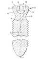
図1を参照すると、本発明の好適な実施例に従って、すり割付き茎用ねじアセンブリは、椎体の骨のような骨に挿入可能の先端部32を有する締結具30と、その頂端部にある拡張可能の頭部34とを含んでいる。この締結具30は、長手方向軸線A−Aを有すると共に、同締結具の先端部32から拡張可能の頭部34に向かって延びる雄ねじ部36を好ましくは含んでいる。該雄ねじ部36は、拡張可能の頭部34に隣接して配置されるのが好ましい締結具のネック部38で終端している。雄ねじ部36の有する外径はネック部38の直径よりも大きい。該ネック部は、好ましくは凹状面を有していて、後から詳細に説明するように、締結具30が広範囲の角度にわたり自由に枢回するのを可能にする。上述した雄ねじ部36,ネック部38,及び拡張可能の頭部34を有する締結具30は、チタン或いはステンレス鋼のように耐久性があり且つ人体にインプラントすることができる非有機性材料で形成するのが好ましい。
【0027】
図1〜図3を参照すると、拡張可能の頭部34は、先端部32から遠いところにある上端40と、ネック部38に一体的に結合した下端42とを有する。頭部34の外表面44は凸状部を含んでいる。拡張可能な頭部34には凹状部もしくは凹所46が形成されており、該凹所46は締結具30の長手方向軸線A−Aに中心があることが好ましい。この凹所46は、ある内法寸法の内表面48を有する。また、頭部34は、後から詳細に説明するように、該頭部の拡張及び収縮を可能にするため、該頭部の外面及び内面間に延在する複数のスロット50を含んでいる。
【0028】
図1及び図2を参照すると、好ましい締結具の拡張可能な頭部34は、その外表面44及び内表面48間に延在する6個のスロット50を含んでいる。該スロット50は、頭部34の周囲のまわりにほぼ一様に離間して配置されている。図2に示すように、第1のスロット50aの中心は、隣接する第2のスロット50bの中心から、符号A1で表わされた角度だけずれている。好ましい実施例においては、角度A1は約60°である。図2の実施例は6個のスロットを開示しているが、唯一つのスロットを含め、任意の数のスロットを頭部に形成してよい。これらのスロット50は、拡張可能な頭部34を分割して複数の可撓性のあるアーム部52とする。各アーム部は、ネック部に隣接して締結具に一体的に結合された下端と、そこから離遠した上端とを有する。図2に示すように、可撓性のアーム部52は、凹所46をほぼ囲んでおり、そして好ましくは、この凹所46の周辺周りに一様に離間した配置となっている。可撓性の各アーム部52は、その上端のところに、凹所46の中心にある長手方向軸線A−Aに向かって該アーム部から延びるタブ54を有している。図3に示すように、凹所46の内表面48は、締結具30の長手方向軸線A−Aに対して角度A2を規定している。この角度A2は、一つの実施例において約15°である。
【0029】
図4,図6及び図7を参照すると、本発明の茎用ねじアセンブリはまた、拡張可能の頭部(図2)にある凹状部内に少なくとも部分的に位置決め及び/又は固定しうるインサートもしくは挿入部材56を含んでいる。図4に示すように、このインサート56は、放射状表面の上端58と、放射状表面の下端60と、該上端及び下端58,60間に延在する外表面62とを有している。また、インサート56は、該上端及び下端間に延びる符号B−Bで表わされた長手方向軸線を有すると共に、外表面62の最大直径部周りに延びるフランジ部64を含んでいる。換言すれば、フランジ部64は、インサート56の最大外法寸法を規定している。しかし、他の好適な実施例においては、フランジ部は、インサート56の最大外法寸法を規定していない。
【0030】
インサートの外表面62は、符号D1で表わされた第1直径の第1部分66を有する。この第1部分66は、インサート56の上端58とフランジ部64との間に延在している。インサート56の外表面は、インサート56の下端60とフランジ部64との間に延在する第2部分68を有している。インサート56の外法寸法はフランジ部64のところで符号D2で表わされた第2直径を有し、これは第1直径D1よりも大きい。インサートの下端60とフランジ部64との間において、外表面62は、インサートの長手方向軸線B−Bに関して符号A3で表わされた角度で内向きに傾斜している。図3及び4Aを参照して、インサート56の角度A3は、このインサートが後から詳しく説明する理由のため頭部34の外表面44を拡開できるように、凹所46の角度A2よりも大きいのが好ましい。図4に示したインサートは実質的に球面状の下端を有しているが、図5に示すように、インサート56’の下端60’は実質的に平らであってもよい。
【0031】
図8及び図9を参照して、茎用ねじアセンブリはまた、整形ロッドを締結具30(図1)と接続するための継手要素70を含んでいる。この継手要素70は、上端72及び下端74と、上端から下端に延びる符号C−Cで表わされた長手方向軸線とを有する。また、継手要素70は、その下端74のところに凸状部を含む外表面76を有している。この外表面は、整形ロッドを茎用ねじアセンブリに着座させるのに使用される強制もしくはパースエイダー(persuader)機器のような取付要素もしくは工具を用いて継手要素を把持及び/又は操作しうるように、上述の外表面には溝78が形成されることが好ましい。該溝78は継手要素の長手方向軸線C−Cに対して実質的に垂直の方向に延びることが好ましい。
【0032】
孔80は、締結具を受けるため継手要素70の長手方向軸線C−Cに沿って延びている。この孔80は、上端72の近くに雌ねじ部84を有し下端74近くに拡張空所86を有する継手要素の内表面82を画成している。拡張空所86の下端は、拡張可能な頭部(図1)の凸状外表面を受けるための凹状面を備えた座部88を有するのが好ましい。拡張空所86の内法寸法D3は、拡張可能な頭部(図2)が通常の未拡開状態にあるとき、該頭部の外表面の外法寸法よりも大きい直径を有する。その結果、締結具及び継手要素は、後から詳細に説明するように、頭部が未拡開であるとき、互いに関して自由に回転及び揺動ができる。
【0033】
図10〜図14は、すり割付き茎用ねじアセンブリを組み立てる方法の好適な一例を示している。図10を参照して、締結具30の先端部32は、継手要素70の上端のところで同継手要素の孔80(図9)に通される。締結具30の雄ねじ部36は、同雄ねじ部36の外径が継手要素の雌ねじ部84の直径よりも小さいので、自由に孔を通ることができる。しかし、一旦頭部34が雌ねじ部84に到達すれば、締結具30は、頭部34の外径が雌ねじ部84の直径よりも大きいので、もはや孔80を自由に通ることはできない。
【0034】
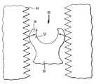
図11を参照して、孔80を通り継手要素の下端に向かう締結具30の頭部34の移動を継続するために、頭部34の可撓性アーム部52は、該頭部を押し縮めるべく、矢印により示された方向に互いの方に向かって内方に湾曲しなければならない。押し縮められている状態下では、頭部34の外径は、継手要素の雌ねじ部84の直径よりも小さいか、或いはその直径に等しい。図12を参照して、一旦頭部34が雌ねじ部84を越えて移動し拡張空所86に入ると、可撓性のアーム部52は、矢印により表わした方向に自由に移動して互いに遠ざかる。可撓性のアーム部52は、頭部34が押し縮められていない状態にあるときの該頭部34の外径よりも拡張空所86の内径の方が大きいので、元の向きに自由に復帰する。
【0035】
図15及び図16を参照して、他の好適な実施例においては、頭部34’の外径は継手要素70’の雌ねじ部84’の直径よりも小さい。その結果、頭部34’は雌ねじ部84’に沿って自由に通ることができる。これらの実施例において、孔は、継手要素70’の拡開空所86’と雌ねじ部84’との間に位置した最小直径部85’を有している。図15に示すように、可撓性のアーム部52’は頭部を縮めるために互いの方に向かい内方に移動しなければならない。押し縮められている状態下では、頭部34’の外径は、継手要素70’の最小直径部85’の直径よりも小さいか、或いはその直径に等しい。図16を参照して、一旦頭部34’が最小直径部85’を越えて移動し拡張空所86’に入ると、可撓性のアーム部52’は、自由に移動して互いに遠ざかり、頭部34’をその元の押し縮められていない状態に戻す。最小直径部は、継手要素70’の中心軸線C−Cに向かい内方に突き出るフランジ部85’でよい。
【0036】
図13は、拡張可能の頭部34が継手要素の拡開空所86内に位置付けられた後の締結具30と継手要素70とを示している。拡張可能な頭部34の外表面は拡開空所86の内径よりも小さい直径を有するので、拡張可能な頭部34及び締結具30は継手要素70に関して自由に枢回する。減少直径のネック部38は、締結具30が継手要素70に関して広い角度範囲にわたり枢回することを可能とする。インサート56(図4)はその後、拡張可能の頭部34の凹所46内に少なくとも部分的に配置される。
【0037】
図17〜図19は、インサート56を凹所46内に少なくとも部分的に設けるための好適な方法の一例を示している。図17は、インサート56の外表面62が頭部34の可撓性アーム部52に係合する前に該頭部34の凹所46近くにあるそのインサート56を示している。フランジ部64のところにおけるインサート56の外法寸法は、凹所46の内法寸法88よりも大きい。凹所46の内法寸法88は、可撓性のアーム部52の上端にある対峙したタブ54間に延びている。
【0038】
図18において、インサート56は、可撓性のアーム部52に当接しており、そして下方向に移動して凹所46の中に入る。その結果、インサートの外表面62はタブ54に係合して、可撓性のアーム部52を矢印で示す方向に強制的に遠ざける。図19を参照して、可撓性のアーム部52は、インサート56のフランジ部64がタブ54を通過するまで、互いに遠ざかるように曲り続け、通過すると、可撓性のアーム部52は、自由に移動して矢印で指示した方向に互いの方に向かい戻る。その後はタブ54がインサート56を凹所46内に少なくとも部分的に固定状態に保持する。凹所内に保持された状態で、インサート56の上端58は、後から詳細に説明する理由により、頭部34の上端40よりも上方にあることが好ましい。一旦インサート56がタブ54により固定されると、インサートの外表面62は可撓性のアーム部52の内表面48、即ち、凹所46の内表面に密接に係合しているため、可撓性のアーム部52はもはや互いの方に内向きに縮むことはできない。その結果、一旦インサート56が凹所46内に固定されてしまえば、拡張可能な頭部の可撓性のアーム部52を著しく操作することなくインサートを凹所から除去することは非常に難しい。
【0039】
図14及び図20を参照して、一旦インサート56が凹所46内に取り付けられると、インサート56及び締結具30は、継手要素70に関して一緒に自由に揺動することができる。図20に示すように、インサート56は、凹所46内に完全に固定されてしまわない方が好ましく、また、拡張可能な頭部34の上端40に関して比較的に鮮明な輪郭を呈するのが望ましい。その結果、インサート56の上端58は、継手要素内に配置される整形ロッド(図示せず)が頭部34に接触するのを防止するため、締結具30の上端40よりも上方に位置することになる。
【0040】
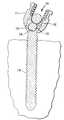
図21を参照して、インサート56が拡張可能な頭部34の凹所46内に取り付けられた後、茎用ねじアセンブリは骨90に挿入する準備ができる。第1のステップにおいて、締結具30は、パイロットホールをこの骨に穿孔することにより骨90に留めうる。次に、締結具30の先端部32はパイロットホールの中に入れられ、駆動体もしくはその他の工具を用いて骨にねじ込まれる。駆動体はねじ回しでよく、或いは後から詳細に説明するように、同駆動体から延びて頭部に形成された1つ以上のスロット内に嵌るように設計された1つ以上の突起部を含んでいてよい。ねじ付きの締結具30は、同締結具の十分な部分が骨の中に留められるまで、骨90内に埋め込まれる。
【0041】
締結具30を骨90の中に留めた後、継手要素70はこの締結具に関して自由に揺動及び回転する。この揺動及び/又は回転動作は、整形ロッド92を継手要素70のロッド受容開口94内に配置させることが必要になる可能性がある。ロッド受容開口94は、継手要素の頂部のところでU字形開口により規定するのが好ましい。上述したように、締結具30のネック部38は、凹状面と、締結具の雄ねじ部の直径よりも小さな直径とを有している。その結果、継手要素70は、ネック部が頭部34の下端まで全面的に延びている場合に可能であるよりも広い範囲の角度にわたり、締結具30の長手方向軸線A−Aに関して揺動しうる。その後、整形ロッド92をロッド受容開口94内に配置できるように、継手要素70を揺動及び/又は回転させうる。継手要素は溝78を使用して動かしてもよいし、或いは同継手要素の本体部を把持することにより動かしてもよい。
【0042】
整形ロッド92を配設した後、雄ねじ部を有する止めねじ(ロック部材)96が継手要素70の雌ねじ部84に螺入される。止めねじ96は、整形ロッド92に当るまで、雌ねじ部84にねじ込まれ続ける。その後、止めねじ96は、整形ロッド92をロッド受容開口もしくはチャンネル94内にロックするため、更に回転され雌ねじ部に入る。この止めねじ96が下向きの力を整形ロッド92に作用し、そして該整形ロッド92が下向きの力をインサート56に作用する。インサート56に作用する下向きの力により、同インサートが更に凹所46内に移動して、可撓性のアーム部52を互いに遠ざかる方向に無理に押し、頭部34の外法寸法を拡大する。止めねじ96を締め続けると、拡張可能な頭部34の外面44が継手要素70の座部88に接触して、継手要素を所定位置にロックすると共に、締結具に関する継手要素の更なる揺動運動を防止する。拡張可能である頭部の特質は、剛な頭部を有する締結具で得られるよりも大きな表面接触面積を頭部と継手要素の間に与えるのに備えている。拡張可能な頭部は、該頭部と継手要素の座部の間により大きな摩擦力を与えるので、発生するロック力は十分に大きい。
【0043】
図22〜図31は本発明の好適な実施例に従ったすり割付き茎用ねじアセンブリを示している。図22は、先端部132,雄ねじ部136,ネック部138及び拡張可能な頭部を含むねじ込み締結具130を示しており、該頭部は、頭部を可撓性のアーム部に押し込むための凹所及びスロットを有する。茎用ねじアセンブリはまた、継手要素170を含んでいる。締結具130及び継手要素170は、図1及び図8に関して上述したものと実質的に同様である。
【0044】
図23〜図25を参照して、茎用ねじアセンブリ用のインサート156は、上端158と、放射状表面をもつ下端160と、該上端及び下端間に延在する外表面162とを有している。インサート156の上端158は、そこから外方に延びる半径方向の突起部198を有する。該半径方向の突起部198は、拡張可能な頭部(図1)に形成されたスロット内に嵌る大きさに作られている。このインサートは、その上端に、六角棒スパナ,或いはねじ回しのような駆動体を受けるために形成された受け口199を含んでいる。インサートはまた、突起部の直下に設けられたフランジ部164を含んでいる。このフランジ部は、外表面162の最大直径部の周りに延びると共に、好ましくは、インサートの外法寸法を規定している。インサートの外表面は、同インサートが移動して頭部の凹所の中に更に入りながら同頭部の可撓性のアーム部を互いに遠ざかる方向に押し込むことができるように、同インサートの長手方向軸線に関してある角度で内向きに傾斜している。
【0045】
図26は、拡張可能な頭部134の凹所内に取り付けられた図23のインサート156を備える部分図を示している。同インサートは、図17〜図19に関して上述した方法とほぼ同様の工程を用いて凹所146内に取り付けられている。インサートの上端158から延びる半径方向の突起部198が頭部134のスロット150内に配置されている。頭部の可撓性のアーム部152は、インサート156により、互いの方に向かい内方に曲がるのを阻止されている。ある実施例においては、インサートの外表面162(図25)により、アーム部152が互いの方に向かい内方に曲がるのを阻止していてよい。図27を参照して、インサート156を締結具130の頭部に取り付けた後、締結具及びインサートは継手要素170に関して一緒に自由に枢回する。
【0046】
図28及び図29を参照して、締結具は、最初にパイロットホールを骨190に穿孔し、次いで該締結具の先端部132をこのパイロットホールに挿入することによって、骨190に固定しうる。しかる後、六角棒スパナのような駆動体をインサート156の上端のところに形成された受け口199に挿入する。駆動体がインサート156を回転させるときに、締結具を骨190にねじ込むためにインサート156の半径方向突起部158が頭部134の可撓性アーム部に係合する。締結具を骨190内に留めた後、継手要素170は締結具に関して自由に揺動し回転するので、整形ロッド192を継手要素170のロッド受容開口194内に配置しうるように、継手要素170は締結具に関して自由に揺動し回転する。整形ロッド192が配置された後、雄ねじ部を有するロック部材196が継手要素170の雌ねじ部184を通るように該雌ねじ部と係合し、そしてロック部材196の下端197が整形ロッド192に係合するまで、該整形ロッド192に向かい進められる。ロック部材196は、下向きの力を整形ロッド192に与えるため、雌ねじ部184内に続けてねじ込まれる。次いで整形ロッド192が下向きの力をインサート156の上端158に与えて、同インサート156を拡張可能な頭部134の凹所146内に更に押し込む。該インサートが更に移動されて拡張可能な頭部134の凹所146内に入るにつれて、インサートの外表面144が可撓性のアーム部152を互いに遠ざかるように強制的に動かして、拡張可能な頭部の外径を拡大させる。その結果、拡張可能な頭部の外表面は継手要素170の座部188に係合して、該継手要素を締結具130に関して所定位置にロックすると共に、締結具に関する該継手要素の更なる揺動運動を阻止する。
【0047】
図30〜図37は、本発明の更なる好適な実施例に従った茎用ねじアセンブリのためのインサート256を示している。この特定実施例において、締結具230及び継手要素270は上述した実施例と実質的に同一の構造である。しかしながら、図30及び図31を参照すると、インサート256は、実質的に球状である形状の外表面262と、頂部258のところにある最小直径部264とを有している。インサート256の外表面262が球状の形状であることにより、同インサートは、締結具230の頭部234の凹所246内で自由に回転するのが可能である。
【0048】
図32〜図34は、図30及び図31のインサート256を用いてすり割付き茎用ねじアセンブリを組み立てるための好適な方法を示している。図32を参照して、締結具230の先端部232は継手要素270の孔280に通される。締結具230の雄ねじ部236は、同雄ねじ部236の外径が継手要素270の孔280の最小径よりも小さいので、該孔280を自由に通ることができる。上述したように、孔の最小径は、継手要素270の雌ねじ部284か、或いは、フランジ部(例えば、図15における部分85’)のような、継手要素の孔の設計に組み込まれた別の特徴により規定することができる。しかし、一旦頭部234が継手要素270の最小直径部に到達すれば、締結具230は、頭部234の外径が最小径よりも大きいので、もはや孔280を自由に通ることはできない。
【0049】
図33は、拡張可能な頭部234が継手要素270の拡張空所286内に配置された後の締結具230及び継手要素270を示している。拡張可能な頭部234の外表面は拡張空所286の内径よりも小さな直径を有するので、拡張可能な頭部234及び締結具230は継手要素270に関して自由に枢回できる。径が減少されている締結具のネック部238は、締結具230及び継手要素270が互いに関して広い角度範囲にわたり枢回することを可能にする。
【0050】
図34及び図35を参照して、その後、インサート256が拡張可能な頭部234の凹所246内に少なくとも部分的に配置される。該インサート256はこの凹所246内に頭部234の可撓性アーム部252により保持される。この時点で、インサート256は凹所246内で自由に回転し、また、継手要素270は締結具230に関して自由に枢回し回転する。図36を参照して、整形ロッド292をロッド受容開口294内に取り付けた後、該整形ロッド292がインサート256を更に凹所245内に押し込むときに拡張可能な頭部234の拡開が行われる。
【0051】
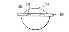
図37は、本発明の他の好適な実施例に従った茎用ねじアセンブリ用のインサート356を示している。このインサート356は、その上端358に半径方向の突起部398を有している。上端358は、特に、整形ロッドを締結具の頭部から離した状態に維持しておくために、放射状湾曲を有する表面を画成している(図1)。この放射状湾曲の表面はまた、整形ロッドを継手要素内に取り付ける前の継手要素に関する締結具の運動を容易にする。インサートは、図17〜図19に示すように拡張可能な頭部の可撓性アーム部により固定されるための径方向のフランジ部364を含んでいる。
【0052】
図38は、本発明の更に別の実施例に従った茎用ねじアセンブリを示している。この茎用ねじアセンブリは、図1〜図3に示した実施例と実質的に同一の締結具430を含んでいる。該締結具430は、拡張可能な頭部434と、該拡張可能な頭部に形成された凹所446と、複数の可撓性アーム部452とを含んでいる。該締結具430は、凹所446の底部のところに形成された受け口402を有する。締結具を骨の中に入れ込むために該受け口に工具を挿入しうる。また、茎用ねじアセンブリは、上端458から下端460まで延びる孔401を有するインサート456を含むことが好ましい。この孔401は、上述した工具が該孔を通過して、締結具を骨内に入れ込むため凹所446の底部のところに形成された受け口402に入るのを可能にするようになった、軸方向孔であることが好ましい。
【0053】
図39を参照すると、好適な一実施例において、締結具530を骨590の中にねじ込むための駆動体591は、下向きに延びる複数のピンもしくはフォーク597のある下端595を備えたシャフト593を含んでいる。該フォーク597は、締結具530の頭部534にあるスロット550に嵌まり込む大きさに作られている。シャフト593が回転すると、フォーク597が頭部534の可撓性アーム部544に係合して、締結具530を回転させ、骨590の中にねじ込む。
【0054】
図40及び図41は、本発明の更なる好適な実施例に従って締結具630を骨690の中にねじ込む駆動体691を示している。この駆動体691は、図39に示したものと実質的に同一であり、下端695を有するシャフト693と、頭部634のスロット650に嵌り込む大きさに作られた下向きに延びる複数のフォーク697とを含んでいる。該駆動体は、好ましくはシャフト693とフォーク697(図40)との間に雄ねじ部699を含んでいる。該雄ねじ部699は継手要素670の雌ねじ部684と螺合可能に組み合うよう設計されている。このように組み合う駆動体の雄ねじ部699及び雌ねじ部684の係合により、締結具630を骨690の中にねじ込むときに茎用ねじアセンブリ全体が通常安定化する。
【0055】
上に論じた諸特徴を上述のように改変及び組合せたもの、また、その他のように改変及び組合せたものも使用可能であるから、好適な実施例についての上述の説明は、特許請求の範囲に規定された本発明を限定するというよりは、例示であると考えるべきである。
【図面の簡単な説明】
【図1】 本発明の一実施形態に係る茎用ねじアセンブリに用いる締結具の斜視図である。
【図2】 図1に示す締結具の平面図である。
【図3】 図1に示す締結具の部分的な断面図である。
【図4】 本発明の一実施形態に係る茎用ねじアセンブリに用いるインサートの側面図である。
【図5】 図4とは別の実施形態に係る茎用ねじアセンブリに用いるインサートの側面図である。
【図6】 図4に示すインサートの斜視図である。
【図7】 図4に示すインサートの平面図である。
【図8】 本発明の一実施形態に係る茎用ねじアセンブリに用いる継手要素の斜視図である。
【図9】 図8に示す継手要素の部分的な断面図である。
【図10】 図1に示す締結具を図8に示す継手要素と組み合せる茎用ねじアセンブリの組立方法を示す側面図である。
【図11】 図10に示すサブアセンブリの次の組立工程における部分的な概略側面図である。
【図12】 図11に示すサブアセンブリの次の組立工程における部分的な概略側面図である。
【図13】 図10〜図12に示すサブアセンブリの次の組立工程における側面図である。
【図14】 図13に示すサブアセンブリの次の組立工程における側面図である。
【図15】 別の実施形態によるサブアセンブリの図11に対応した部分的な断面図である。
【図16】 別の実施形態によるサブアセンブリの図12に対応した部分的な断面図である。
【図17】 図4に示すインサートと図1に示す締結具とを組合わせる方法の第1ステップを示す部分的な概略側面図である。
【図18】 図17に示すサブアセンブリの組立工程の第2ステップにおける部分的な概略側面図である。
【図19】 図17に示すサブアセンブリの組立工程の第3ステップにおける部分的な概略側面図である。
【図20】 図14に示す茎用ねじアセンブリの部分断面図である。
【図21】 図14に示す茎用ねじアセンブリにおける継手要素のロッド受容開口内に整形ロッドを取付けた状態を表す側面図である。
【図22】 本発明の別の実施形態に係る茎用ねじアセンブリを示す斜視図である。
【図23】 図22に示す茎用ねじアセンブリに用いるインサートの斜視図である。
【図24】 図23に示すインサートの平面図である。
【図25】 図24の線XXV−XXVによる断面図である。
【図26】 図22に示す茎用ねじアセンブリの部分斜視図である。
【図27】 図22に示す茎用ねじアセンブリの図26とは別の部分斜視図である。
【図28】 図22に示す茎用ねじアセンブリの平面図である。
【図29】 締結具を骨内に留めると共に整形ロッドを継手要素のロッド受容開口内に取付けた状態における図22に示す茎用ねじアッセンブリの、図28の線XXIX−XXIXによる断面図である。
【図30】 本発明の更に別の実施形態に係る茎用ねじアセンブリに用いるインサートの斜視図である。
【図31】 図30に示すインサートの側面図である。
【図32】 図30に示すインサートを茎用ねじアセンブリに組み立てる一方法の第1ステップを示す側面図である。
【図33】 図32に示す茎用ねじアセンブリの組立工程の第2ステップにおける側面図である。
【図34】 図33に示す茎用ねじアセンブリの組立工程の第3ステップにおける側面図である。
【図35】 図34に示す茎用ねじアセンブリの部分的に拡大した断面図である。
【図36】 図34に示す茎用ねじアセンブリにおける継手要素のロッド受容開口内に整形ロッドを取付けた状態を表す断面図である。
【図37】 本発明の更に別の実施形態に係る茎用ねじアセンブリに用いるインサートの側面図である。
【図38】 本発明の更に別の実施形態に係る茎用ねじアセンブリに用いるインサート及び締結具の側面図である。
【図39】 本発明のある好適な実施形態に従った、茎用ねじアセンブリの締結具を骨の中にねじ込むための駆動体の斜視図である。
【図40】 本発明の更なる好適な実施例に従った、茎用ねじアセンブリの締結具を骨の中にねじ込むための駆動体の斜視図である。
【図41】 図40に示す駆動体が締結具と係合した状態を示す斜視図である。
【符号の説明】
30 締結具
32 締結具の先端部
34 締結具の頭部
34' 締結具の頭部
44 締結具の外表面
46 締結具の凹所
48 締結具の内表面
50 頭部にあるスロット
52 可撓性アーム部
52' 可撓性アーム部
54 可撓性アーム部にあるタブ
56 インサート
56' インサート
58 インサートの上端
60 インサートの下端
62 インサートの外表面
64 インサートのフランジ部
70 継手要素
70' 継手要素
72 継手要素の上端
74 継手要素の下端
84 頭部を受ける孔
88 継手要素の座部
90 骨
92 整形ロッド
94 ロッド受容開口
96 止めねじ(ロック部材)
130 締結具
132 締結具の先端部
134 締結具の頭部
146 締結具の凹所
150 頭部にあるスロット
152 可撓性アーム部
156 インサート
158 インサートの上端
160 インサートの下端
164 インサートのフランジ部
170 継手要素
188 継手要素の座部
190 骨
192 整形ロッド
194 ロッド受容開口
196 止めねじ(ロック部材)
230 締結具
232 締結具の先端部
234 締結具の頭部
256 インサート
262 インサートの外表面
270 インサート
292 整形ロッド
294 ロッド受容開口
356 インサート
358 インサートの上端
364 インサートのフランジ部
430 締結具
434 締結具の頭部
446 締結具の凹所
452 可撓性アーム部
456 インサート
458 インサートの上端
460 インサートの下端
530 締結具
534 締結具の頭部
544 可撓性アーム部
550 頭部にあるスロット
590 骨
630 締結具
690 骨[0001]
BACKGROUND OF THE INVENTION
The present invention relates to spinal fixation devices, and more particularly, to a pedicle screw assembly having an expandable pedicle screw. In a preferred embodiment, the stem screw assembly includes a joint element having a seat, the seat receives the head of the stem screw, and movement about the multi-axis of the stem screw relative to the joint element. And the stem screw assembly expands the head of the stem screw so as to prevent relative movement of the joint element and stem screw, and the seat of the joint element. Includes an insert that presses against.
[0002]
[Prior art]
The spinal column is a very complex system of bone and connective tissue that allows the body to support and protects the fine spine and nerves. The vertebral column includes a series of vertebrae stacked one on top of the other, where each vertebral body includes relatively solid bone portions that form the lateral surface (cortex) of the vertebral body. And a relatively weak bone part forming the central part of the vertebral body (sponge-like). There is an intervertebral disc between each vertebral body, which provides for buffering and suppression of compressive forces applied to the spinal column. The spinal canal containing the fine spinal cord and nerves is located in the back of the vertebral body.
[0003]
A variety of spinal column diseases are known, such as side bay disease (abnormal lateral curvature of the spine), posterior bay disease (usually an abnormal anterior curvature of the spine in the thoracic spine), excessive anterior bay disease (usually Is an abnormal posterior curvature of the spine in the lumbar spine), spondylolisthesis (usually anterior displacement of another vertebra on one vertebra in the lumbar or cervical spine), and other diseases. Other diseases are caused by abnormalities, diseases or disorders such as intervertebral disc cracks or dislocations, degenerative disc disease, vertebral fractures and the like. Patients suffering from such illnesses usually experience extremely debilitating pain in addition to a decrease in nerve function.
[0004]
The present invention relates to a technique commonly referred to as spinal fixation, in which adjacent implants of the spine are fused and / or mechanically fixed together using a surgical implant. Spine fixation is also used to change each other's alignment of adjacent vertebrae to change the overall alignment of the spine. Such techniques have been used effectively to treat the above mentioned diseases and in most cases to relieve the pain experienced by the patient. However, as will be described in detail later, there are several drawbacks associated with current fixation devices.
[0005]
One spinal fixation technique involves fixing the spine by using a shaping rod, commonly referred to as a spinal rod, that extends generally parallel to the spine. This is done by exposing the spine from the back and securing the bone screws to the appropriate pedicles. Two pedicle screws are usually provided per vertebra, ie, at each stalk on either side of the spinous process, and serve as fixation points for the spinal rod. Thereafter, a clamping element adapted to receive the spinal rod is used to couple the spinal rod to the stem screw. Due to the adjusting influence of the spinal rod, the spine is subjected to a force that follows the more desirable shape. In one example, the spinal rod may bend to achieve the desired curved spine.
[0006]
US Pat. No. 5,129,388 to Vignaud et al. Discloses a spinal fixation device that includes a stem screw with a rigid U-shaped head connected thereto. The U-shaped head includes a U-shaped channel for receiving a spinal rod therein. Since the U-shaped head is provided with the female screw portion, a set screw having a male screw portion can be screwed into the female screw portion. After inserting the pedicle screw into the bone and placing the spinal rod into the U-shaped channel, the set screw is screwed into the female threaded portion of the coupling element to secure the spinal rod within the U-shaped channel and the spinal rod And prevent relative movement between stem screws. The spinal fixation device also includes a cap that covers the upper portion of the U-shaped element to prevent the U-shaped element arm from spreading when the set screw is screwed into the U-shaped head.
[0007]
[Problems to be solved by the invention]
Surgeons have often experienced considerable difficulty in attempting to insert spinal fixation devices such as those disclosed in the aforementioned US Pat. No. 5,129,388. For example, surgeons often have not been able to efficiently and properly place the spinal rod into the U-shaped head of the bone screw. This is because the U-shaped heads of the stem screws often do not align with each other because the spinal curvature and the orientation of the stem on which the screw is provided are different. The spinal rod is often bent on multiple planes to connect the stem screw to the spinal rod, which will weaken the connection with the spinal rod. In addition, these problems can lengthen surgery considerably and increase the potential for complications associated with surgery.
[0008]
In response to the problems identified in the above-mentioned U.S. Pat. No. 5,129,388, U.S. Pat. No. 5,733,286 to Errico et al., U.S. Pat. No. 5, to Biedermann et al., Nos. 672,176 and U.S. Pat. No. 5,476,464 to Metz-Stavenhagen are multiaxial, in which the fixation element secured to the bone has a spherical head. A spinal fixation device is disclosed. The spinal fixation devices in these US patents have a shaping rod capture assembly that attaches the shaping rod within the capture assembly and connects the shaping rod to the fixation element. The spherical head of the fixation element allows the fixation element to move relative to the shaping rod capture assembly. However, the above-mentioned U.S. patents do not eliminate all of the disadvantages found in U.S. Pat. No. 5,129,388 because each spinal fixation device may shift after insertion. . This is mainly due to the insufficient surface contact area between the spherical head of the fixation element and the shaping rod capture assembly. Also, the spinal fixation device is complex and difficult to manufacture.
[0009]
Another polyaxial bone anchoring device is taught in International Patent Publication No. WO 88/03781. This publication describes a device for fixing a bone screw in an opening in a bone connecting plate. The head of the bone screw is provided with a longitudinal groove that allows the head to expand after being placed in one of the openings in the osteosynthesis plate. After inserting the screw into one of the openings, an adjustment screw is screwed into the hole at the top of the head to expand the head. The outer surface of the expanded head presses against the opening in the bone bonding plate so as to secure the screw to the bone bonding plate. U.S. Pat. No. 4,484,570 also discloses a bone screw for use in connection with an osteosynthesis plate, the bone screw having a head with a central opening and a plurality of slots. The opening and the slot divide the head into a plurality of tongues. A central opening in the head is inserted with a spreading tool having a conical surface to widen the head and to lock the bone screw with respect to the osteosynthesis plate. However, those described in International Patent Publication No. WO88 / 03781 and US Pat. No. 4,484,570 are related to the bone plate and are not spinal fixation devices using shaping rods.
[0010]
In spite of the devices described above, prior art spinal fixation devices are limited in their methods of locking the screw head, the complexity of use, the difficulty of properly positioning the shaping rod and rod capture assembly, and some complex devices. There is room for improvement in the operations required for a large number of parts related to, as well as the post-operative movement of the rod capture assembly with respect to the bone anchoring device derived from the weak interface between the two.
[0011]
[Means for Solving the Problems]
The screw assembly for stems according to the present invention is configured as follows to solve the above problems. The pedicle screw assembly includes a fastener having a tip for insertion into the bone and an expandable head at the opposite end of the tip. The head may be expandable by the material forming it or by its structure. One preferred structure for the expandable head includes a head formed with one or more slots. In this case, the expandable head includes an outer surface that includes a convex portion, a recess that defines an inner surface having internal dimensions, and an inner surface and an outer surface to allow expansion of the head. Preferably it has at least one slot extending. The stem screw assembly also includes an insert that can be positioned at least partially within the recess in the head. The insert has an outer surface that includes an outer dimension that is greater than the inner dimension of the recess described above. In this case, the insert may be rotatable with the recess in the head.
[0012]
The stem screw assembly also includes a coupling element for coupling the stem screw to the shaping rod. The coupling element preferably has a hole extending through the coupling element for receiving the fastener and a seat for receiving the head of the fastener. The seat includes a concave portion that receives the convex portion of the head and allows the fastener and coupling element to pivot relative to each other before being locked to prevent further pivotal movement. May be. The stem screw assembly may further include a locking member associated with the coupling element. The locking member locks the shaping rod within the coupling element after the shaping rod is disposed within the coupling element. The locking member is preferably adapted to push the insert into the recess in the head such that the outer dimension of the insert abuts the inner dimension of the head, and the coupling element is further pivoted with respect to the fastener. In order to prevent movement, the head expands and strikes the joint element seat.
[0013]
The expandable head of the fastener provides for an improved level of surface contact between the head and the seat of the coupling element. This improvement in the surface contact level results in a more reliable locking force. Also, the locking force increases due to the frictional force acting at the interface between the fastener head and the coupling element. This frictional force is proportional to the normal force of the fastener head on the seat of the coupling element and thus increases as the insert acts to expand the fastener head. As a result, the possibility of post-operative displacement and / or movement of the spinal rod or joint element with respect to one or more bone fasteners is significantly reduced. Furthermore, the stem screw assembly of the present invention has a reduced number of parts. As a result, the implantation procedure is greatly simplified and the possibility of the component falling into the patient's body is greatly reduced.
[0014]
Preferably, the fastener is a pedicle bone screw having a male thread extending from the tip of the screw toward the head. The fastener may have one or more holes in the male thread to receive bone graft material as disclosed in Sutter U.S. Pat. No. 4,484,570. Instead of using a screw to secure the screw to the bone, in another suitable case, the fastener is as disclosed in US Pat. No. 5,476,464 to Metz-Stavenhagen mentioned above. A hook-shaped fixing element may be included. The fastener may also be a structure having barbs on its outer surface so that the fastener is forced into the bone and the beard is pulled out of the bone. Is prevented. The fastener preferably includes a neck between the head and the tip, and the neck is preferably located near the head. The neck portion has a concave surface and usually has a diameter that is smaller than the diameter of the male thread portion of the fastener. The head of the fastener preferably includes a recess that defines an inner surface having internal dimensions. The head also includes a plurality of slots extending between its inner and outer surfaces. The fastener preferably has a longitudinal axis extending from the tip to the head, and the recess and the inner and outer surfaces of the fastener are centered about the longitudinal axis. The slot begins approximately at the top surface of the head and extends toward the distal end of the fastener in a direction generally parallel to the longitudinal axis. The plurality of slots divides the head into two or more flexible arm portions at the upper end of the fastener. In one preferred case, the head is formed with six slots to divide the head into six flexible arm portions. The flexible arm is preferably configured to bend away from the longitudinal axis to expand the outer surface of the head. The flexible arm can also bend toward the longitudinal axis to shrink the head so as to reduce the outer dimensions of the head and allow for assembly of fasteners into the coupling elements. .
[0015]
The expandable head also preferably includes at least one tab that extends into the recess to at least partially secure the insert within the recess. The tabs are preferably formed at the distal ends of the flexible arm portions, and each flexible arm portion preferably includes one tab. These flexible arms are typically arranged in a substantially annular shape around the outer peripheral surface of the recess, with the tab extending into the recess to secure the insert.
[0016]
The insert preferably has an upper end, a lower end, and a longitudinal axis extending between the upper and lower ends. The insert also preferably includes an outer surface and a flange portion extending around the outer surface between its upper and lower ends. In a preferred case, the flange portion is in a plane substantially perpendicular to the longitudinal axis of the insert. The flange preferably defines the outer dimension of the insert, i.e. the part of the insert having the largest diameter. In other words, the flange portion provides the maximum diameter portion of the insert. When viewed from the side or in a side sectional view, the outer surface of the insert is inclined inward from the flange portion toward the lower end of the insert. In this case, the lower end shape of the insert is substantially spherical. However, in other cases, the lower end of the insert is flat. The upper end of the insert preferably has a radial surface adapted to engage the shaping rod. This top radial surface ensures good surface contact between the shaping rod and the insert, regardless of the angle of the insert with respect to the shaping rod. When the insert is positioned at least partially within the recess of the expandable head, the upper end of the insert, in particular to prevent the shaping rod from contacting the fastener head, It extends beyond.
[0017]
In other suitable cases, the insert includes at least one, preferably a plurality of radial projections extending outwardly from the periphery of the insert. This radial projection is preferably provided at the upper end of the insert, and each projection is in a slot formed in the head that is expandable when the insert is at least partially disposed in the recess. It is made into a size that extends into one. The insert has a radial flange portion that is preferably disposed directly below the radial protrusion and a receptacle formed at the upper end of the insert. The receiving port receives a driving body such as a screwdriver or a hexagonal wrench. In this case, the fastener is attached to the bone by inserting the driver into the receptacle of the insert and then turning the driver to rotate the insert clockwise or counterclockwise. The insert transmits drive torque from the drive body to the fastener. This driving torque is transmitted from the insert to the fastener at the interface between the radial protrusion and the slot.
[0018]
In other preferred cases, the insert does not have a receptacle, but has an axial hole extending through the insert. In these specific cases, a receiving port sized to receive the driving body is formed in the portion of the head where the recess is provided. When the insert is at least partially positioned in the recess, the hole extending through the insert is substantially aligned with the receptacle formed in the head so that the driver passes through the hole and the head passes. It is possible to reach the receiving port of the department. Thereafter, in order to fix the fastener to the bone, the driving body is rotated and the fastener is rotated clockwise or counterclockwise.
[0019]
The coupling element preferably includes a substantially U-shaped member having an upper end and a lower end and a longitudinal axis extending between the upper and lower ends. The coupling element has an inner surface defining an aperture extending in a direction substantially parallel to the longitudinal axis and an outer surface. The inner surface of the coupling element defines the shape of the hole that receives the fastener. In this case, the hole extends in a direction substantially parallel to the longitudinal axis of the coupling element. The coupling element preferably includes a thread adapted to be screwed onto the locking member. In this case, the threaded portion is formed on the inner surface of the coupling element, and the locking member includes a set screw having a male threaded portion that threads into the female threaded portion of the coupling element. However, in other suitable cases, the thread may be formed on the outer surface of the coupling element and the locking member has an internal thread adapted to threadably engage with a thread on the outer surface of the coupling element. Includes lock nut. The coupling element may also have one or more recesses or grooves formed in the coupling element to receive an adjustment device such as a persuader device that seats the shaping rod on the coupling element. In this case, the depression or groove extends substantially in a direction substantially perpendicular to the longitudinal axis of the coupling element.
[0020]
Its inner surface at the lower end of the coupling element has a concave part for receiving the convex part of the head and for allowing the head to swing relative to the coupling element before it is locked in place. A containing seat is preferably defined. This seat is preferably provided near the lower end of the coupling element in the expansion cavity. The expansion cavity preferably has a diameter larger than the diameter of the female screw portion.
[0021]
During assembly of the pedicle screw assembly described above, the fastener tip is positioned within the expansion cavity with the expandable head contacting its convex outer surface with the concave seat of the coupling element. Threaded through a hole in the coupling element. In one preferred case, this is done by passing the distal end of the fastener toward the lower end of the coupling element and through its upper end. As the tip and thread of the fastener proceed toward the lower end of the joint element, the head passes past the smaller diameter portion of the joint element hole because its outer surface has a diameter greater than the minimum diameter of the joint element hole. It must be shrunk so that it can. In the preferred case, the smallest diameter portion of the hole is defined by the female thread of the coupling element. However, in other cases, the smallest diameter portion may be an inwardly extending protrusion such as an annular ring. As a result, the flexible arm portion of the head must bend inward to contract the head, and when bent, the head can pass through the small diameter portion of the joint element. The head continues to pass through the joint element in a contracted state until reaching the expansion cavity, upon which the flexible arm is free to return to its original non-curved position.
[0022]
Once the insert is positioned within the recess, the flexible arm portion cannot bend inward because the outer dimension of the insert abuts the portion of the head where the recess is formed. For this reason, the head can no longer contract. Furthermore, the fastener cannot be removed from the coupling element as long as the insert remains fixed in the portion where the recess in the head is formed.
[0023]
After the fastener is screwed into the bone during spinal fusion surgery, the joint element swings freely with respect to the fastener and with respect to the insert secured thereto. The fastener neck, which preferably has a concave surface with a diameter smaller than the diameter of the thread of the fastener, allows the coupling element to swing over a wider angular range with respect to the longitudinal axis of the fastener. Thus, the shaping rod can be more easily placed in the rod receiving opening of the coupling element. After placing the shaping rod in the rod receiving opening, the shaping rod is locked in place by screwing the locking member into the threaded portion of the coupling element. Once the locking member has fully tightened the shaping rod, the shaping rod now exerts a downward force on the insert. The insert is then moved further into the recess to force the flexible arms away from each other to widen the fastener head. As the head expands, the area of the head that engages the seat of the joint element increases and the normal force that the head exerts on the seat increases. Therefore, the friction force acting along the boundary surface between the head and the joint element is proportional to the normal force, so that the friction force also increases. The increased surface contact area between the head and the coupling element and the increased frictional force increase the locking force between them and prevent the coupling element from further pivoting or rocking movement with respect to the fastener. As a result, the likelihood of post-operative complications for spinal or spinal transplant patients is minimized because the likelihood that the pedicle screw assembly will shift and / or move post-operatively is greatly reduced. In one preferred case of the invention, the coupling element secures the shaping rod just above the head of the fastener. However, in other suitable cases, the coupling element is disclosed in US Pat. No. 5,344,422 to Frigg and US Pat. No. 5,584,831 to McKay. As described above, the shaping rod may be configured to be eccentrically held from the longitudinal axis of the stem screw.
[0024]
The present invention also includes a tool for attaching the fastener into the bone. The tool is preferably a driver having a rotatable shaft and one or more pins or forks extending from the end of the shaft to engage the slot. In the preferred case, the driver has one fork for each slot in the head of the fastener. This drive body may also have an external thread at the lower end of the shaft. This male thread is preferably adapted to engage the female thread of the coupling element when the fastener is screwed into the bone. Engagement of the male thread portion of the driver and the female thread portion of the coupling element improves the stability of the stem screw assembly when the fastener is secured or attached to the bone. In particular, the engagement of the threaded portion prevents relative movement of the coupling element with respect to the fastener when the fastener is screwed into the bone and simplifies the introduction of the fastener.
[0025]
These and other objects, features and advantages of the present invention will become more readily apparent upon reading the detailed description of the preferred embodiments set forth below, taken in conjunction with the accompanying drawings.
[0026]
DETAILED DESCRIPTION OF THE INVENTION
Referring to FIG. 1, in accordance with a preferred embodiment of the present invention, a slotted pedicle screw assembly includes a
[0027]
With reference to FIGS. 1-3, the
[0028]
With reference to FIGS. 1 and 2, the preferred fastener
[0029]
4, 6 and 7, the pedicle screw assembly of the present invention is also an insert or insert that can be at least partially positioned and / or secured within a recess in the expandable head (FIG. 2). A
[0030]
The
[0031]
With reference to FIGS. 8 and 9, the pedicle screw assembly also includes a
[0032]
The
[0033]
10-14 show a preferred example of a method for assembling a slotted stem screw assembly. Referring to FIG. 10, the
[0034]
Referring to FIG. 11, in order to continue the movement of the
[0035]
Referring to FIGS. 15 and 16, in another preferred embodiment, the outer diameter of the
[0036]
FIG. 13 shows the
[0037]
FIGS. 17-19 illustrate an example of a suitable method for providing the
[0038]
In FIG. 18, the
[0039]
Referring to FIGS. 14 and 20, once the
[0040]
Referring to FIG. 21, after the
[0041]
After fastening the
[0042]
After the shaping
[0043]
22-31 show a slotted stem screw assembly according to a preferred embodiment of the present invention. FIG. 22 shows a threaded
[0044]
Referring to FIGS. 23-25, an
[0045]
FIG. 26 shows a partial view with the
[0046]
Referring to FIGS. 28 and 29, the fastener can be secured to
[0047]
FIGS. 30-37 illustrate an
[0048]
FIGS. 32-34 illustrate a preferred method for assembling a slotted pedicle screw assembly using the
[0049]
FIG. 33 shows the
[0050]
With reference to FIGS. 34 and 35, the
[0051]
FIG. 37 illustrates an
[0052]
FIG. 38 illustrates a pedicle screw assembly according to yet another embodiment of the present invention. This pedicle screw assembly includes a
[0053]
Referring to FIG. 39, in one preferred embodiment, a
[0054]
40 and 41 show a
[0055]
Since the features discussed above may be modified and combined as described above, as well as others modified and combined, the above description of the preferred embodiments is described in the claims. It should be considered illustrative rather than limiting the invention as defined in.
[Brief description of the drawings]
FIG. 1 is a perspective view of a fastener used in a stem screw assembly according to an embodiment of the present invention.
FIG. 2 is a plan view of the fastener shown in FIG.
FIG. 3 is a partial cross-sectional view of the fastener shown in FIG.
FIG. 4 is a side view of an insert used in a stem screw assembly according to an embodiment of the present invention.
FIG. 5 is a side view of an insert used in a pedicle screw assembly according to another embodiment different from FIG. 4;
6 is a perspective view of the insert shown in FIG. 4. FIG.
7 is a plan view of the insert shown in FIG. 4. FIG.
FIG. 8 is a perspective view of a coupling element used in a stem screw assembly according to an embodiment of the present invention.
9 is a partial cross-sectional view of the joint element shown in FIG.
10 is a side view showing a method for assembling a pedicle screw assembly in which the fastener shown in FIG. 1 is combined with the joint element shown in FIG. 8;
FIG. 11 is a partial schematic side view of the subassembly shown in FIG. 10 in the next assembly step.
FIG. 12 is a partial schematic side view of the subassembly shown in FIG. 11 in the next assembly step.
FIG. 13 is a side view of the subassembly shown in FIGS. 10 to 12 in the next assembly step.
FIG. 14 is a side view of the subassembly shown in FIG. 13 in the next assembly step.
15 is a partial cross-sectional view corresponding to FIG. 11 of a subassembly according to another embodiment.
FIG. 16 is a partial cross-sectional view corresponding to FIG. 12 of a subassembly according to another embodiment.
17 is a partial schematic side view showing a first step of a method of combining the insert shown in FIG. 4 and the fastener shown in FIG. 1;
FIG. 18 is a partial schematic side view in a second step of the assembly process of the subassembly shown in FIG. 17;
FIG. 19 is a partial schematic side view of the third step in the assembly process of the subassembly shown in FIG. 17;
20 is a partial cross-sectional view of the pedicle screw assembly shown in FIG. 14;
FIG. 21 is a side view showing a state in which a shaping rod is attached in a rod receiving opening of a joint element in the stem screw assembly shown in FIG. 14;
FIG. 22 is a perspective view of a stem screw assembly according to another embodiment of the present invention.
FIG. 23 is a perspective view of an insert used in the stem screw assembly shown in FIG.
24 is a plan view of the insert shown in FIG. 23. FIG.
25 is a cross-sectional view taken along line XXV-XXV in FIG. 24. FIG.
26 is a partial perspective view of the pedicle screw assembly shown in FIG. 22. FIG.
27 is a partial perspective view different from FIG. 26 of the stem screw assembly shown in FIG. 22. FIG.
FIG. 28 is a plan view of the stem screw assembly shown in FIG. 22;
29 is a cross-sectional view of the stem screw assembly shown in FIG. 22 taken along line XXIX-XXIX in FIG. 28 with the fasteners secured in the bone and the shaping rod mounted in the rod receiving opening of the coupling element.
30 is a perspective view of an insert used in a stem screw assembly according to still another embodiment of the present invention. FIG.
31 is a side view of the insert shown in FIG. 30. FIG.
32 is a side view showing the first step of one method of assembling the insert shown in FIG. 30 into the stem screw assembly. FIG.
33 is a side view of the second step in the assembling process of the stem screw assembly shown in FIG. 32; FIG.
34 is a side view of the third step in the assembly process of the stem screw assembly shown in FIG. 33; FIG.
35 is a partially enlarged cross-sectional view of the pedicle screw assembly shown in FIG. 34. FIG.
36 is a cross-sectional view illustrating a state in which the shaping rod is attached in the rod receiving opening of the joint element in the pedicle screw assembly shown in FIG. 34;
FIG. 37 is a side view of an insert used in a stem screw assembly according to still another embodiment of the present invention.
FIG. 38 is a side view of an insert and fastener used in a stem screw assembly according to yet another embodiment of the present invention.
FIG. 39 is a perspective view of a driver for screwing a fastener of a pedicle screw assembly into bone according to a preferred embodiment of the present invention.
FIG. 40 is a perspective view of a driver for screwing a fastener of a pedicle screw assembly into bone according to a further preferred embodiment of the present invention.
41 is a perspective view showing a state in which the driving body shown in FIG. 40 is engaged with a fastener. FIG.
[Explanation of symbols]
30 fasteners
32 Tip of fastener
34 Fastener head
34 'Fastener head
44 Outer surface of fastener
46 Recessed fastener
48 Inner surface of fastener
50 Slot in the head
52 Flexible Arm
52 'flexible arm
54 Tabs on flexible arms
56 inserts
56 'insert
58 Top of insert
60 Bottom of insert
62 Outer surface of insert
64 Insert flange
70 Joint elements
70 'joint element
72 Top of joint element
74 Lower end of joint element
84 Hole to receive the head
88 Joint element seat
90 bones
92 Shaping rod
94 Rod receiving opening
96 Set screw (locking member)
130 Fastener
132 Tip of Fastener
134 Fastener head
146 Fastener recess
150 slot in the head
152 Flexible Arm
156 insert
158 Top of insert
160 Bottom of insert
164 Insert flange
170 Joint element
188 Joint element seat
190 bones
192 Shaping rod
194 Rod receiving opening
196 Set screw (locking member)
230 Fastener
232 Tip of fastener
234 Fastener head
256 insert
262 Insert outer surface
270 insert
292 Shaping rod
294 Rod receiving opening
356 insert
358 Top of insert
364 Insert flange
430 Fastener
434 Fastener head
446 Recess of fastener
452 Flexible Arm
456 insert
458 Top of insert
460 Bottom of insert
530 Fastener
534 Head of fastener
544 Flexible arm part
550 Slot at head
590 bone
630 fastener
690 bone
Claims (14)
Translated fromJapanese(b)前記凹所内に少なくとも部分的に配置することができ、外表面を有すると共に前記凹所の前記内法寸法よりも大きい外法寸法を規定する、インサートと、
(c)ロッド受容開口と、前記締結具の前記頭部を受ける孔と、前記締結具の前記頭部を受ける座部とを含む継手要素であって、該座部は、前記頭部の前記凸状部を受けると共に、前記締結具がそこにロックされる前の前記継手要素に関して枢回するのを可能にする凹状部を含む、前記継手要素と、
(d)前記継手要素に関連したロック部材であって、該ロック部材は、前記ロッド受容開口内に配置される整形ロッドに強制的に押し付けられて、前記インサートの前記外法寸法が前記頭部の前記内法寸法に当接されるように、前記インサートを前記頭部の前記凹所内に押し込むようになっていて、前記継手要素が前記締結具に関して枢回運動するのを阻止するため前記頭部が拡開して前記継手要素の前記座部に当る、前記ロック部材と、
を備えた茎用ねじアセンブリ。(A) a distal end for insertion into the bone and an expandable head at an end opposite the distal end, the head comprising an outer surface including a convex portion, an inner A fastener having a surface and a recess defining an internal dimension;
(B) an insert that can be at least partially disposed within the recess and has an outer surface and defines an outer dimension that is greater than the inner dimension of the recess;
(C) A joint element including a rod receiving opening, a hole for receiving the head portion of the fastener, and a seat portion for receiving the head portion of the fastener, wherein the seat portion is formed on the head portion. The coupling element comprising a concave portion for receiving a convex portion and allowing the fastener to pivot with respect to the coupling element before being locked therein;
(D) a locking member associated with the joint element, the locking member being forced against a shaping rod disposed in the rod receiving opening, wherein the outer dimension of the insert is the head The insert is pushed into the recess in the head so as to abut against the internal dimension of the head to prevent the joint element from pivoting with respect to the fastener. The locking member, wherein the portion expands and hits the seat of the joint element;
Stem screw assembly with.
Applications Claiming Priority (2)
| Application Number | Priority Date | Filing Date | Title |
|---|---|---|---|
| US09/414,272US6554834B1 (en) | 1999-10-07 | 1999-10-07 | Slotted head pedicle screw assembly |
| US09/414272 | 1999-10-07 |
Related Child Applications (1)
| Application Number | Title | Priority Date | Filing Date |
|---|---|---|---|
| JP2010171998ADivisionJP5080622B2 (en) | 1999-10-07 | 2010-07-30 | Fitting element for stem screw assembly |
Publications (2)
| Publication Number | Publication Date |
|---|---|
| JP2001140919A JP2001140919A (en) | 2001-05-22 |
| JP4594509B2true JP4594509B2 (en) | 2010-12-08 |
Family
ID=23640731
Family Applications (2)
| Application Number | Title | Priority Date | Filing Date |
|---|---|---|---|
| JP2000308713AExpired - Fee RelatedJP4594509B2 (en) | 1999-10-07 | 2000-10-10 | Stem screw assembly |
| JP2010171998AExpired - Fee RelatedJP5080622B2 (en) | 1999-10-07 | 2010-07-30 | Fitting element for stem screw assembly |
Family Applications After (1)
| Application Number | Title | Priority Date | Filing Date |
|---|---|---|---|
| JP2010171998AExpired - Fee RelatedJP5080622B2 (en) | 1999-10-07 | 2010-07-30 | Fitting element for stem screw assembly |
Country Status (6)
| Country | Link |
|---|---|
| US (1) | US6554834B1 (en) |
| EP (1) | EP1090595B1 (en) |
| JP (2) | JP4594509B2 (en) |
| AU (1) | AU771400B2 (en) |
| CA (1) | CA2321803C (en) |
| DE (1) | DE60007253T2 (en) |
Families Citing this family (303)
| Publication number | Priority date | Publication date | Assignee | Title |
|---|---|---|---|---|
| US6187000B1 (en) | 1998-08-20 | 2001-02-13 | Endius Incorporated | Cannula for receiving surgical instruments |
| DE60136980D1 (en)* | 2000-03-28 | 2009-01-22 | Showa Ika Kogyo Co Ltd | Spine implant, drive tool and nut guide |
| AU2001280476B2 (en)* | 2000-06-30 | 2005-11-24 | Stephen Ritland | Polyaxial connection device and method |
| AU2006200772B2 (en)* | 2000-06-30 | 2009-04-02 | Stephen Ritland | Polyaxial connection device and method |
| US7056321B2 (en) | 2000-08-01 | 2006-06-06 | Endius, Incorporated | Method of securing vertebrae |
| US7985247B2 (en) | 2000-08-01 | 2011-07-26 | Zimmer Spine, Inc. | Methods and apparatuses for treating the spine through an access device |
| US7833250B2 (en)* | 2004-11-10 | 2010-11-16 | Jackson Roger P | Polyaxial bone screw with helically wound capture connection |
| US7837716B2 (en)* | 2000-08-23 | 2010-11-23 | Jackson Roger P | Threadform for medical implant closure |
| US6485491B1 (en)* | 2000-09-15 | 2002-11-26 | Sdgi Holdings, Inc. | Posterior fixation system |
| US8512380B2 (en) | 2002-08-28 | 2013-08-20 | Warsaw Orthopedic, Inc. | Posterior fixation system |
| DE10055888C1 (en)* | 2000-11-10 | 2002-04-25 | Biedermann Motech Gmbh | Bone screw, has connector rod receiving part with unsymmetrically arranged end bores |
| US6726689B2 (en) | 2002-09-06 | 2004-04-27 | Roger P. Jackson | Helical interlocking mating guide and advancement structure |
| US8377100B2 (en) | 2000-12-08 | 2013-02-19 | Roger P. Jackson | Closure for open-headed medical implant |
| US6488681B2 (en)* | 2001-01-05 | 2002-12-03 | Stryker Spine S.A. | Pedicle screw assembly |
| FR2823095B1 (en) | 2001-04-06 | 2004-02-06 | Ldr Medical | RACHIS OSTEOSYNTHESIS DEVICE AND PLACEMENT METHOD |
| US7862587B2 (en) | 2004-02-27 | 2011-01-04 | Jackson Roger P | Dynamic stabilization assemblies, tool set and method |
| US10729469B2 (en) | 2006-01-09 | 2020-08-04 | Roger P. Jackson | Flexible spinal stabilization assembly with spacer having off-axis core member |
| US8353932B2 (en) | 2005-09-30 | 2013-01-15 | Jackson Roger P | Polyaxial bone anchor assembly with one-piece closure, pressure insert and plastic elongate member |
| US8292926B2 (en) | 2005-09-30 | 2012-10-23 | Jackson Roger P | Dynamic stabilization connecting member with elastic core and outer sleeve |
| US10258382B2 (en) | 2007-01-18 | 2019-04-16 | Roger P. Jackson | Rod-cord dynamic connection assemblies with slidable bone anchor attachment members along the cord |
| US6974460B2 (en)* | 2001-09-14 | 2005-12-13 | Stryker Spine | Biased angulation bone fixation assembly |
| FR2833151B1 (en)* | 2001-12-12 | 2004-09-17 | Ldr Medical | BONE ANCHORING IMPLANT WITH POLYAXIAL HEAD |
| US7163538B2 (en)* | 2002-02-13 | 2007-01-16 | Cross Medical Products, Inc. | Posterior rod system |
| EP1474053A1 (en)* | 2002-02-13 | 2004-11-10 | Cross Medical Products, Inc. | Posterior polyaxial system for the spine |
| US20040006342A1 (en)* | 2002-02-13 | 2004-01-08 | Moti Altarac | Posterior polyaxial plate system for the spine |
| US6740086B2 (en) | 2002-04-18 | 2004-05-25 | Spinal Innovations, Llc | Screw and rod fixation assembly and device |
| US11224464B2 (en) | 2002-05-09 | 2022-01-18 | Roger P. Jackson | Threaded closure with inwardly-facing tool engaging concave radiused structures and axial through-aperture |
| DE20207851U1 (en) | 2002-05-21 | 2002-10-10 | Metz-Stavenhagen, Peter, Dr.med., 34537 Bad Wildungen | Anchoring element for fastening a rod of a device for setting up a human or animal spine to a vertebral bone |
| US7060066B2 (en)* | 2002-06-28 | 2006-06-13 | Mayo Foundation For Medical Education And Research | Spinal fixation support device and methods of using |
| US8257402B2 (en) | 2002-09-06 | 2012-09-04 | Jackson Roger P | Closure for rod receiving orthopedic implant having left handed thread removal |
| WO2006052796A2 (en) | 2004-11-10 | 2006-05-18 | Jackson Roger P | Helical guide and advancement flange with break-off extensions |
| US8876868B2 (en) | 2002-09-06 | 2014-11-04 | Roger P. Jackson | Helical guide and advancement flange with radially loaded lip |
| US8282673B2 (en) | 2002-09-06 | 2012-10-09 | Jackson Roger P | Anti-splay medical implant closure with multi-surface removal aperture |
| US9539012B2 (en) | 2002-10-30 | 2017-01-10 | Zimmer Spine, Inc. | Spinal stabilization systems with quick-connect sleeve assemblies for use in surgical procedures |
| US20060095035A1 (en)* | 2004-11-03 | 2006-05-04 | Jones Robert J | Instruments and methods for reduction of vertebral bodies |
| AU2003287273C1 (en) | 2002-10-30 | 2010-01-07 | Zimmer Spine, Inc. | Spinal stabilization system insertion and methods |
| KR100495876B1 (en)* | 2002-11-25 | 2005-06-16 | 유앤아이 주식회사 | bone fixation appratus and assembling method and tool |
| US7887539B2 (en) | 2003-01-24 | 2011-02-15 | Depuy Spine, Inc. | Spinal rod approximators |
| US7141051B2 (en)* | 2003-02-05 | 2006-11-28 | Pioneer Laboratories, Inc. | Low profile spinal fixation system |
| US6994012B2 (en)* | 2003-02-26 | 2006-02-07 | Keith Investments, Llc | Drive units and drive assemblies |
| US8540753B2 (en)* | 2003-04-09 | 2013-09-24 | Roger P. Jackson | Polyaxial bone screw with uploaded threaded shank and method of assembly and use |
| US7621918B2 (en) | 2004-11-23 | 2009-11-24 | Jackson Roger P | Spinal fixation tool set and method |
| US6716214B1 (en) | 2003-06-18 | 2004-04-06 | Roger P. Jackson | Polyaxial bone screw with spline capture connection |
| US7615068B2 (en)* | 2003-05-02 | 2009-11-10 | Applied Spine Technologies, Inc. | Mounting mechanisms for pedicle screws and related assemblies |
| US20050182401A1 (en)* | 2003-05-02 | 2005-08-18 | Timm Jens P. | Systems and methods for spine stabilization including a dynamic junction |
| US20050177164A1 (en)* | 2003-05-02 | 2005-08-11 | Carmen Walters | Pedicle screw devices, systems and methods having a preloaded set screw |
| US7635379B2 (en)* | 2003-05-02 | 2009-12-22 | Applied Spine Technologies, Inc. | Pedicle screw assembly with bearing surfaces |
| US7377923B2 (en) | 2003-05-22 | 2008-05-27 | Alphatec Spine, Inc. | Variable angle spinal screw assembly |
| US8366753B2 (en)* | 2003-06-18 | 2013-02-05 | Jackson Roger P | Polyaxial bone screw assembly with fixed retaining structure |
| US7766915B2 (en) | 2004-02-27 | 2010-08-03 | Jackson Roger P | Dynamic fixation assemblies with inner core and outer coil-like member |
| US7776067B2 (en) | 2005-05-27 | 2010-08-17 | Jackson Roger P | Polyaxial bone screw with shank articulation pressure insert and method |
| US8092500B2 (en) | 2007-05-01 | 2012-01-10 | Jackson Roger P | Dynamic stabilization connecting member with floating core, compression spacer and over-mold |
| US8926670B2 (en) | 2003-06-18 | 2015-01-06 | Roger P. Jackson | Polyaxial bone screw assembly |
| US8137386B2 (en) | 2003-08-28 | 2012-03-20 | Jackson Roger P | Polyaxial bone screw apparatus |
| US8398682B2 (en) | 2003-06-18 | 2013-03-19 | Roger P. Jackson | Polyaxial bone screw assembly |
| US8257398B2 (en)* | 2003-06-18 | 2012-09-04 | Jackson Roger P | Polyaxial bone screw with cam capture |
| US8377102B2 (en) | 2003-06-18 | 2013-02-19 | Roger P. Jackson | Polyaxial bone anchor with spline capture connection and lower pressure insert |
| US7967850B2 (en) | 2003-06-18 | 2011-06-28 | Jackson Roger P | Polyaxial bone anchor with helical capture connection, insert and dual locking assembly |
| US7753958B2 (en) | 2003-08-05 | 2010-07-13 | Gordon Charles R | Expandable intervertebral implant |
| FR2859376B1 (en)* | 2003-09-04 | 2006-05-19 | Spine Next Sa | SPINAL IMPLANT |
| US7588575B2 (en) | 2003-10-21 | 2009-09-15 | Innovative Spinal Technologies | Extension for use with stabilization systems for internal structures |
| US7967826B2 (en)* | 2003-10-21 | 2011-06-28 | Theken Spine, Llc | Connector transfer tool for internal structure stabilization systems |
| US7261715B2 (en)* | 2003-11-24 | 2007-08-28 | Sdgi Holdings, Inc. | Grommet assembly |
| WO2005058134A2 (en)* | 2003-12-12 | 2005-06-30 | Kinetikos Medical Incorporated | Apparatuses, systems and methods for bone fixation |
| US7527638B2 (en) | 2003-12-16 | 2009-05-05 | Depuy Spine, Inc. | Methods and devices for minimally invasive spinal fixation element placement |
| US7179261B2 (en) | 2003-12-16 | 2007-02-20 | Depuy Spine, Inc. | Percutaneous access devices and bone anchor assemblies |
| US11419642B2 (en) | 2003-12-16 | 2022-08-23 | Medos International Sarl | Percutaneous access devices and bone anchor assemblies |
| WO2005065397A2 (en)* | 2003-12-30 | 2005-07-21 | Depuy Spine Sarl | Bone anchor assemblies |
| JP2007516811A (en)* | 2003-12-30 | 2007-06-28 | デピュイ・スパイン・エスエイアールエル | Bone anchor assembly and method for manufacturing bone anchor assembly |
| US7678137B2 (en)* | 2004-01-13 | 2010-03-16 | Life Spine, Inc. | Pedicle screw constructs for spine fixation systems |
| US7163539B2 (en)* | 2004-02-27 | 2007-01-16 | Custom Spine, Inc. | Biased angle polyaxial pedicle screw assembly |
| US8097020B2 (en)* | 2004-02-27 | 2012-01-17 | Custom Spine, Inc. | Pedicle dynamic facet arthroplasty system and method |
| US7160300B2 (en) | 2004-02-27 | 2007-01-09 | Jackson Roger P | Orthopedic implant rod reduction tool set and method |
| US7862594B2 (en)* | 2004-02-27 | 2011-01-04 | Custom Spine, Inc. | Polyaxial pedicle screw assembly |
| US7892257B2 (en) | 2004-02-27 | 2011-02-22 | Custom Spine, Inc. | Spring loaded, load sharing polyaxial pedicle screw assembly and method |
| US8152810B2 (en) | 2004-11-23 | 2012-04-10 | Jackson Roger P | Spinal fixation tool set and method |
| JP2007525274A (en) | 2004-02-27 | 2007-09-06 | ロジャー・ピー・ジャクソン | Orthopedic implant rod reduction instrument set and method |
| US7819902B2 (en)* | 2004-02-27 | 2010-10-26 | Custom Spine, Inc. | Medialised rod pedicle screw assembly |
| US20050228380A1 (en)* | 2004-04-09 | 2005-10-13 | Depuy Spine Inc. | Instruments and methods for minimally invasive spine surgery |
| US7678139B2 (en)* | 2004-04-20 | 2010-03-16 | Allez Spine, Llc | Pedicle screw assembly |
| DE102004019638A1 (en)* | 2004-04-22 | 2005-11-17 | Siemens Ag | FET-based sensor for the detection of particularly reducing gases, manufacturing and operating methods |
| US7731736B2 (en)* | 2004-06-14 | 2010-06-08 | Zimmer Spine, Inc. | Fastening system for spinal stabilization system |
| US7766945B2 (en)* | 2004-08-10 | 2010-08-03 | Lanx, Inc. | Screw and rod fixation system |
| US7186255B2 (en)* | 2004-08-12 | 2007-03-06 | Atlas Spine, Inc. | Polyaxial screw |
| US7651502B2 (en) | 2004-09-24 | 2010-01-26 | Jackson Roger P | Spinal fixation tool set and method for rod reduction and fastener insertion |
| US8366747B2 (en)* | 2004-10-20 | 2013-02-05 | Zimmer Spine, Inc. | Apparatus for connecting a longitudinal member to a bone portion |
| US7513905B2 (en)* | 2004-11-03 | 2009-04-07 | Jackson Roger P | Polyaxial bone screw |
| US8926672B2 (en) | 2004-11-10 | 2015-01-06 | Roger P. Jackson | Splay control closure for open bone anchor |
| US7572279B2 (en) | 2004-11-10 | 2009-08-11 | Jackson Roger P | Polyaxial bone screw with discontinuous helically wound capture connection |
| US8308782B2 (en) | 2004-11-23 | 2012-11-13 | Jackson Roger P | Bone anchors with longitudinal connecting member engaging inserts and closures for fixation and optional angulation |
| US9216041B2 (en) | 2009-06-15 | 2015-12-22 | Roger P. Jackson | Spinal connecting members with tensioned cords and rigid sleeves for engaging compression inserts |
| US9980753B2 (en) | 2009-06-15 | 2018-05-29 | Roger P Jackson | pivotal anchor with snap-in-place insert having rotation blocking extensions |
| WO2006057837A1 (en) | 2004-11-23 | 2006-06-01 | Jackson Roger P | Spinal fixation tool attachment structure |
| US7875065B2 (en) | 2004-11-23 | 2011-01-25 | Jackson Roger P | Polyaxial bone screw with multi-part shank retainer and pressure insert |
| US9168069B2 (en) | 2009-06-15 | 2015-10-27 | Roger P. Jackson | Polyaxial bone anchor with pop-on shank and winged insert with lower skirt for engaging a friction fit retainer |
| US8444681B2 (en) | 2009-06-15 | 2013-05-21 | Roger P. Jackson | Polyaxial bone anchor with pop-on shank, friction fit retainer and winged insert |
| WO2006058221A2 (en) | 2004-11-24 | 2006-06-01 | Abdou Samy M | Devices and methods for inter-vertebral orthopedic device placement |
| US7799062B2 (en)* | 2004-11-30 | 2010-09-21 | Stryker Trauma S.A. | Self-guiding threaded fastener |
| US7935137B2 (en) | 2004-12-08 | 2011-05-03 | Depuy Spine, Inc. | Locking bone screw and spinal plate system |
| US7736380B2 (en) | 2004-12-21 | 2010-06-15 | Rhausler, Inc. | Cervical plate system |
| US20060167465A1 (en)* | 2005-01-27 | 2006-07-27 | Erasmo Lopez | System for facilitating attachment of a delivery instrument with a bone screw |
| US7901437B2 (en) | 2007-01-26 | 2011-03-08 | Jackson Roger P | Dynamic stabilization member with molded connection |
| US7476239B2 (en)* | 2005-05-10 | 2009-01-13 | Jackson Roger P | Polyaxial bone screw with compound articulation |
| US10076361B2 (en) | 2005-02-22 | 2018-09-18 | Roger P. Jackson | Polyaxial bone screw with spherical capture, compression and alignment and retention structures |
| US7951175B2 (en) | 2005-03-04 | 2011-05-31 | Depuy Spine, Inc. | Instruments and methods for manipulating a vertebra |
| US7951172B2 (en) | 2005-03-04 | 2011-05-31 | Depuy Spine Sarl | Constrained motion bone screw assembly |
| US7914536B2 (en)* | 2005-03-11 | 2011-03-29 | Aesculap Ag | Bone repair device and method |
| US7338491B2 (en)* | 2005-03-22 | 2008-03-04 | Spinefrontier Inc | Spinal fixation locking mechanism |
| US20060235385A1 (en)* | 2005-03-31 | 2006-10-19 | Dale Whipple | Low profile polyaxial screw |
| CA2614898C (en)* | 2005-04-27 | 2014-04-22 | Trinity Orthopedics, Llc | Mono-planar pedilcle screw method, system, and kit |
| US7811310B2 (en) | 2005-05-04 | 2010-10-12 | Spinefrontier, Inc | Multistage spinal fixation locking mechanism |
| WO2007011431A2 (en)* | 2005-07-18 | 2007-01-25 | Dong Myung Jeon | Bi-polar bone screw assembly |
| US7766946B2 (en)* | 2005-07-27 | 2010-08-03 | Frank Emile Bailly | Device for securing spinal rods |
| US7761849B2 (en)* | 2005-08-25 | 2010-07-20 | Microsoft Corporation | Automated analysis and recovery of localization data |
| CH705709B1 (en)* | 2005-08-29 | 2013-05-15 | Bird Biedermann Ag | Spinal implant. |
| WO2007040553A1 (en)* | 2005-09-26 | 2007-04-12 | Dong Jeon | Hybrid jointed bone screw system |
| US8105368B2 (en) | 2005-09-30 | 2012-01-31 | Jackson Roger P | Dynamic stabilization connecting member with slitted core and outer sleeve |
| US12357348B2 (en) | 2005-09-30 | 2025-07-15 | Roger P. Jackson | Method of assembling a pivotal bone anchor assembly with press-in-place insert |
| US7927359B2 (en)* | 2005-10-06 | 2011-04-19 | Paradigm Spine, Llc | Polyaxial screw |
| US7722651B2 (en) | 2005-10-21 | 2010-05-25 | Depuy Spine, Inc. | Adjustable bone screw assembly |
| GB0521582D0 (en) | 2005-10-22 | 2005-11-30 | Depuy Int Ltd | An implant for supporting a spinal column |
| US7704271B2 (en) | 2005-12-19 | 2010-04-27 | Abdou M Samy | Devices and methods for inter-vertebral orthopedic device placement |
| GB0600662D0 (en) | 2006-01-13 | 2006-02-22 | Depuy Int Ltd | Spinal support rod kit |
| US8348952B2 (en) | 2006-01-26 | 2013-01-08 | Depuy International Ltd. | System and method for cooling a spinal correction device comprising a shape memory material for corrective spinal surgery |
| US8057519B2 (en)* | 2006-01-27 | 2011-11-15 | Warsaw Orthopedic, Inc. | Multi-axial screw assembly |
| US7722652B2 (en)* | 2006-01-27 | 2010-05-25 | Warsaw Orthopedic, Inc. | Pivoting joints for spinal implants including designed resistance to motion and methods of use |
| US20070191839A1 (en)* | 2006-01-27 | 2007-08-16 | Sdgi Holdings, Inc. | Non-locking multi-axial joints in a vertebral implant and methods of use |
| US7833252B2 (en)* | 2006-01-27 | 2010-11-16 | Warsaw Orthopedic, Inc. | Pivoting joints for spinal implants including designed resistance to motion and methods of use |
| WO2007114834A1 (en)* | 2006-04-05 | 2007-10-11 | Dong Myung Jeon | Multi-axial, double locking bone screw assembly |
| WO2007121271A2 (en) | 2006-04-11 | 2007-10-25 | Synthes (U.S.A) | Minimally invasive fixation system |
| US20070270813A1 (en)* | 2006-04-12 | 2007-11-22 | Laszlo Garamszegi | Pedicle screw assembly |
| US8361129B2 (en) | 2006-04-28 | 2013-01-29 | Depuy Spine, Inc. | Large diameter bone anchor assembly |
| US8133262B2 (en)* | 2006-04-28 | 2012-03-13 | Depuy Spine, Inc. | Large diameter bone anchor assembly |
| ATE505145T1 (en)* | 2006-06-07 | 2011-04-15 | Disc Motion Technologies Inc | PEDICLE SCREW |
| US20080058808A1 (en) | 2006-06-14 | 2008-03-06 | Spartek Medical, Inc. | Implant system and method to treat degenerative disorders of the spine |
| US7922748B2 (en)* | 2006-06-16 | 2011-04-12 | Zimmer Spine, Inc. | Removable polyaxial housing for a pedicle screw |
| CA2658418A1 (en)* | 2006-07-13 | 2008-01-17 | Mass Modular Spine System | Modular spinal fixation system |
| WO2008008511A2 (en)* | 2006-07-14 | 2008-01-17 | Laszlo Garamszegi | Pedicle screw assembly with inclined surface seat |
| US8388660B1 (en) | 2006-08-01 | 2013-03-05 | Samy Abdou | Devices and methods for superior fixation of orthopedic devices onto the vertebral column |
| US8062340B2 (en)* | 2006-08-16 | 2011-11-22 | Pioneer Surgical Technology, Inc. | Spinal rod anchor device and method |
| US7918857B2 (en) | 2006-09-26 | 2011-04-05 | Depuy Spine, Inc. | Minimally invasive bone anchor extensions |
| US20090198291A1 (en)* | 2006-10-26 | 2009-08-06 | Warsaw Orthopedic, Inc. | Bone screw |
| US8162990B2 (en)* | 2006-11-16 | 2012-04-24 | Spine Wave, Inc. | Multi-axial spinal fixation system |
| US9101401B2 (en) | 2006-11-20 | 2015-08-11 | Aesculap Implant Systems, Llc | Bone repair device and method |
| WO2008091266A1 (en)* | 2006-12-07 | 2008-07-31 | Dong Myung Jeon | Spinal rod transverse connector system |
| US8679128B2 (en) | 2006-12-07 | 2014-03-25 | Zimmer Spine, Inc. | Apparatus and methods for reduction of vertebral bodies in a spine |
| CA2670988C (en) | 2006-12-08 | 2014-03-25 | Roger P. Jackson | Tool system for dynamic spinal implants |
| WO2008082836A1 (en)* | 2006-12-29 | 2008-07-10 | Abbott Spine Inc. | Spinal stabilization systems and methods |
| US8636783B2 (en)* | 2006-12-29 | 2014-01-28 | Zimmer Spine, Inc. | Spinal stabilization systems and methods |
| US8366745B2 (en) | 2007-05-01 | 2013-02-05 | Jackson Roger P | Dynamic stabilization assembly having pre-compressed spacers with differential displacements |
| US8475498B2 (en) | 2007-01-18 | 2013-07-02 | Roger P. Jackson | Dynamic stabilization connecting member with cord connection |
| US8231635B2 (en) | 2007-01-18 | 2012-07-31 | Stryker Spine | Polyaxial screwdriver for a pedicle screw system |
| US10792074B2 (en) | 2007-01-22 | 2020-10-06 | Roger P. Jackson | Pivotal bone anchor assemly with twist-in-place friction fit insert |
| KR100991204B1 (en)* | 2007-01-23 | 2010-11-01 | 주식회사 바이오스마트 | Spinos process for spine spacer |
| WO2008094572A2 (en)* | 2007-01-30 | 2008-08-07 | Dong Myung Jeon | Anterior cervical plating system |
| US8926667B2 (en)* | 2007-02-09 | 2015-01-06 | Transcendental Spine, Llc | Connector |
| US8012177B2 (en) | 2007-02-12 | 2011-09-06 | Jackson Roger P | Dynamic stabilization assembly with frusto-conical connection |
| WO2008128105A1 (en)* | 2007-04-12 | 2008-10-23 | Texas Scottish Rite Hospital For Children | Orthopedic fastener for stabilization and fixation |
| US10383660B2 (en) | 2007-05-01 | 2019-08-20 | Roger P. Jackson | Soft stabilization assemblies with pretensioned cords |
| US8979904B2 (en) | 2007-05-01 | 2015-03-17 | Roger P Jackson | Connecting member with tensioned cord, low profile rigid sleeve and spacer with torsion control |
| US8197517B1 (en) | 2007-05-08 | 2012-06-12 | Theken Spine, Llc | Frictional polyaxial screw assembly |
| US8197518B2 (en) | 2007-05-16 | 2012-06-12 | Ortho Innovations, Llc | Thread-thru polyaxial pedicle screw system |
| US7951173B2 (en) | 2007-05-16 | 2011-05-31 | Ortho Innovations, Llc | Pedicle screw implant system |
| US7942909B2 (en) | 2009-08-13 | 2011-05-17 | Ortho Innovations, Llc | Thread-thru polyaxial pedicle screw system |
| US7942911B2 (en) | 2007-05-16 | 2011-05-17 | Ortho Innovations, Llc | Polyaxial bone screw |
| US7947065B2 (en)* | 2008-11-14 | 2011-05-24 | Ortho Innovations, Llc | Locking polyaxial ball and socket fastener |
| US7942910B2 (en) | 2007-05-16 | 2011-05-17 | Ortho Innovations, Llc | Polyaxial bone screw |
| CA2690038C (en) | 2007-05-31 | 2012-11-27 | Roger P. Jackson | Dynamic stabilization connecting member with pre-tensioned solid core |
| US8083772B2 (en) | 2007-06-05 | 2011-12-27 | Spartek Medical, Inc. | Dynamic spinal rod assembly and method for dynamic stabilization of the spine |
| US8052722B2 (en) | 2007-06-05 | 2011-11-08 | Spartek Medical, Inc. | Dual deflection rod system for a dynamic stabilization and motion preservation spinal implantation system and method |
| US8092501B2 (en) | 2007-06-05 | 2012-01-10 | Spartek Medical, Inc. | Dynamic spinal rod and method for dynamic stabilization of the spine |
| US8048128B2 (en) | 2007-06-05 | 2011-11-01 | Spartek Medical, Inc. | Revision system and method for a dynamic stabilization and motion preservation spinal implantation system and method |
| US8021396B2 (en) | 2007-06-05 | 2011-09-20 | Spartek Medical, Inc. | Configurable dynamic spinal rod and method for dynamic stabilization of the spine |
| US8109970B2 (en) | 2007-06-05 | 2012-02-07 | Spartek Medical, Inc. | Deflection rod system with a deflection contouring shield for a spine implant and method |
| US8048123B2 (en) | 2007-06-05 | 2011-11-01 | Spartek Medical, Inc. | Spine implant with a deflection rod system and connecting linkages and method |
| US8114134B2 (en) | 2007-06-05 | 2012-02-14 | Spartek Medical, Inc. | Spinal prosthesis having a three bar linkage for motion preservation and dynamic stabilization of the spine |
| US8048115B2 (en) | 2007-06-05 | 2011-11-01 | Spartek Medical, Inc. | Surgical tool and method for implantation of a dynamic bone anchor |
| US20080312697A1 (en)* | 2007-06-15 | 2008-12-18 | Robert Reid, Inc. | System and Method for Polyaxially Adjustable Bone Anchorage |
| US8313515B2 (en) | 2007-06-15 | 2012-11-20 | Rachiotek, Llc | Multi-level spinal stabilization system |
| JP5085730B2 (en)* | 2007-06-28 | 2012-11-28 | スピナル エレメンツ,インク. | Spine stabilization device |
| US20090005813A1 (en)* | 2007-06-28 | 2009-01-01 | Angela Crall | Apparatus and methods for spinal implants |
| US20090005815A1 (en)* | 2007-06-28 | 2009-01-01 | Scott Ely | Dynamic stabilization system |
| JP2010536533A (en)* | 2007-08-24 | 2010-12-02 | スピナル エレメンツ,インク. | Loop rod spinal fixation device |
| US20090069849A1 (en)* | 2007-09-10 | 2009-03-12 | Oh Younghoon | Dynamic screw system |
| US8414588B2 (en) | 2007-10-04 | 2013-04-09 | Depuy Spine, Inc. | Methods and devices for minimally invasive spinal connection element delivery |
| WO2009055400A1 (en) | 2007-10-23 | 2009-04-30 | K2M, Inc. | Polyaxial screw assembly |
| US8911477B2 (en) | 2007-10-23 | 2014-12-16 | Roger P. Jackson | Dynamic stabilization member with end plate support and cable core extension |
| AU2014202155B2 (en)* | 2007-10-23 | 2015-11-05 | K2M, Inc. | Polyaxial Screw Assembly |
| US20090105756A1 (en)* | 2007-10-23 | 2009-04-23 | Marc Richelsoph | Spinal implant |
| GB0720762D0 (en) | 2007-10-24 | 2007-12-05 | Depuy Spine Sorl | Assembly for orthopaedic surgery |
| US9801667B2 (en)* | 2007-12-07 | 2017-10-31 | Nexus Spine, L.L.C. | Instruments, tools, and methods for presson pedicle screws |
| US20090171395A1 (en)* | 2007-12-28 | 2009-07-02 | Jeon Dong M | Dynamic spinal rod system |
| US20090192548A1 (en)* | 2008-01-25 | 2009-07-30 | Jeon Dong M | Pedicle-laminar dynamic spinal stabilization device |
| US20090194206A1 (en)* | 2008-01-31 | 2009-08-06 | Jeon Dong M | Systems and methods for wrought nickel/titanium alloy flexible spinal rods |
| US9408641B2 (en)* | 2008-02-02 | 2016-08-09 | Globus Medical, Inc. | Spinal rod link reducer |
| US9579126B2 (en) | 2008-02-02 | 2017-02-28 | Globus Medical, Inc. | Spinal rod link reducer |
| WO2009097623A2 (en)* | 2008-02-02 | 2009-08-06 | Texas Scottish Rite Hospital For Children | Pedicle screw |
| US9345517B2 (en) | 2008-02-02 | 2016-05-24 | Globus Medical, Inc. | Pedicle screw having a removable rod coupling |
| US8439922B1 (en) | 2008-02-06 | 2013-05-14 | NiVasive, Inc. | Systems and methods for holding and implanting bone anchors |
| US8057517B2 (en) | 2008-02-26 | 2011-11-15 | Spartek Medical, Inc. | Load-sharing component having a deflectable post and centering spring and method for dynamic stabilization of the spine |
| US8083775B2 (en) | 2008-02-26 | 2011-12-27 | Spartek Medical, Inc. | Load-sharing bone anchor having a natural center of rotation and method for dynamic stabilization of the spine |
| US8048125B2 (en) | 2008-02-26 | 2011-11-01 | Spartek Medical, Inc. | Versatile offset polyaxial connector and method for dynamic stabilization of the spine |
| US8097024B2 (en) | 2008-02-26 | 2012-01-17 | Spartek Medical, Inc. | Load-sharing bone anchor having a deflectable post and method for stabilization of the spine |
| US8211155B2 (en) | 2008-02-26 | 2012-07-03 | Spartek Medical, Inc. | Load-sharing bone anchor having a durable compliant member and method for dynamic stabilization of the spine |
| US8007518B2 (en) | 2008-02-26 | 2011-08-30 | Spartek Medical, Inc. | Load-sharing component having a deflectable post and method for dynamic stabilization of the spine |
| US8337536B2 (en) | 2008-02-26 | 2012-12-25 | Spartek Medical, Inc. | Load-sharing bone anchor having a deflectable post with a compliant ring and method for stabilization of the spine |
| US8267979B2 (en) | 2008-02-26 | 2012-09-18 | Spartek Medical, Inc. | Load-sharing bone anchor having a deflectable post and axial spring and method for dynamic stabilization of the spine |
| US8333792B2 (en) | 2008-02-26 | 2012-12-18 | Spartek Medical, Inc. | Load-sharing bone anchor having a deflectable post and method for dynamic stabilization of the spine |
| US9060813B1 (en) | 2008-02-29 | 2015-06-23 | Nuvasive, Inc. | Surgical fixation system and related methods |
| US8608746B2 (en) | 2008-03-10 | 2013-12-17 | DePuy Synthes Products, LLC | Derotation instrument with reduction functionality |
| US8709015B2 (en) | 2008-03-10 | 2014-04-29 | DePuy Synthes Products, LLC | Bilateral vertebral body derotation system |
| WO2009124196A2 (en)* | 2008-04-03 | 2009-10-08 | Life Spine, Inc. | Top loading polyaxial spine screw assembly with one step lockup |
| ES2368016T3 (en)* | 2008-04-22 | 2011-11-11 | Biedermann Motech Gmbh | INSTRUMENT FOR MOUNTING A BONE ANCHORAGE DEVICE. |
| US10973556B2 (en) | 2008-06-17 | 2021-04-13 | DePuy Synthes Products, Inc. | Adjustable implant assembly |
| WO2009155523A1 (en)* | 2008-06-19 | 2009-12-23 | Life Spine, Inc. | Spinal rod connectors configured to retain spinal rods of varying diameters |
| AU2010260521C1 (en) | 2008-08-01 | 2013-08-01 | Roger P. Jackson | Longitudinal connecting member with sleeved tensioned cords |
| USD601702S1 (en)* | 2008-08-14 | 2009-10-06 | Yechiel Gotfried | Surgical instrument |
| US9603629B2 (en) | 2008-09-09 | 2017-03-28 | Intelligent Implant Systems Llc | Polyaxial screw assembly |
| US8147554B2 (en)* | 2008-10-13 | 2012-04-03 | Globus Medical, Inc. | Intervertebral spacer |
| US20100104999A1 (en)* | 2008-10-23 | 2010-04-29 | Bulloch Scott E | Apparatus, System, and Method for Intra-Oral Distraction |
| US20090143823A1 (en)* | 2008-11-13 | 2009-06-04 | Jeon Dong M | Transverse connector system for spinal rods |
| US8075603B2 (en) | 2008-11-14 | 2011-12-13 | Ortho Innovations, Llc | Locking polyaxial ball and socket fastener |
| US9358050B2 (en) | 2011-10-14 | 2016-06-07 | Globus Medical, Inc. | Orthopedic anchor assembly |
| US8998961B1 (en) | 2009-02-26 | 2015-04-07 | Lanx, Inc. | Spinal rod connector and methods |
| US8241364B2 (en) | 2009-04-02 | 2012-08-14 | Globus Medical, Inc. | Method of installation of intervertebral spacers |
| CN102497828B (en) | 2009-05-20 | 2015-09-09 | 斯恩蒂斯有限公司 | What patient installed retracts part |
| US11229457B2 (en) | 2009-06-15 | 2022-01-25 | Roger P. Jackson | Pivotal bone anchor assembly with insert tool deployment |
| US8998959B2 (en) | 2009-06-15 | 2015-04-07 | Roger P Jackson | Polyaxial bone anchors with pop-on shank, fully constrained friction fit retainer and lock and release insert |
| US9668771B2 (en) | 2009-06-15 | 2017-06-06 | Roger P Jackson | Soft stabilization assemblies with off-set connector |
| CN103826560A (en) | 2009-06-15 | 2014-05-28 | 罗杰.P.杰克逊 | Polyaxial Bone Anchor with Socket Stem and Winged Inserts with Friction Fit Compression Collars |
| USD746461S1 (en) | 2009-06-19 | 2015-12-29 | Life Spine, Inc. | Spinal rod connector |
| US8876869B1 (en)* | 2009-06-19 | 2014-11-04 | Nuvasive, Inc. | Polyaxial bone screw assembly |
| US20110028238A1 (en) | 2009-07-31 | 2011-02-03 | Nike, Inc. | Golf Club With Non-Metallic Fasteners |
| EP2286748B1 (en)* | 2009-08-20 | 2014-05-28 | Biedermann Technologies GmbH & Co. KG | Bone anchoring device |
| EP2485654B1 (en) | 2009-10-05 | 2021-05-05 | Jackson P. Roger | Polyaxial bone anchor with non-pivotable retainer and pop-on shank, some with friction fit |
| US8361123B2 (en) | 2009-10-16 | 2013-01-29 | Depuy Spine, Inc. | Bone anchor assemblies and methods of manufacturing and use thereof |
| CN102695465A (en) | 2009-12-02 | 2012-09-26 | 斯帕泰克医疗股份有限公司 | Low profile spinal prosthesis incorporating a bone anchor having a deflectable post and a compound spinal rod |
| US8764806B2 (en) | 2009-12-07 | 2014-07-01 | Samy Abdou | Devices and methods for minimally invasive spinal stabilization and instrumentation |
| US8617216B2 (en)* | 2010-04-05 | 2013-12-31 | David L. Brumfield | Fully-adjustable bone fixation device |
| US8535318B2 (en) | 2010-04-23 | 2013-09-17 | DePuy Synthes Products, LLC | Minimally invasive instrument set, devices and related methods |
| US8647371B2 (en)* | 2010-04-30 | 2014-02-11 | Globus Medical, Inc. | Locking bone screws and methods of use thereof |
| US12383311B2 (en) | 2010-05-14 | 2025-08-12 | Roger P. Jackson | Pivotal bone anchor assembly and method for use thereof |
| US20110307015A1 (en) | 2010-06-10 | 2011-12-15 | Spartek Medical, Inc. | Adaptive spinal rod and methods for stabilization of the spine |
| US10603083B1 (en) | 2010-07-09 | 2020-03-31 | Theken Spine, Llc | Apparatus and method for limiting a range of angular positions of a screw |
| US9084634B1 (en) | 2010-07-09 | 2015-07-21 | Theken Spine, Llc | Uniplanar screw |
| WO2012030712A1 (en) | 2010-08-30 | 2012-03-08 | Zimmer Spine, Inc. | Polyaxial pedicle screw |
| AU2011299558A1 (en) | 2010-09-08 | 2013-05-02 | Roger P. Jackson | Dynamic stabilization members with elastic and inelastic sections |
| AU2011324058A1 (en) | 2010-11-02 | 2013-06-20 | Roger P. Jackson | Polyaxial bone anchor with pop-on shank and pivotable retainer |
| US9084636B2 (en) | 2011-01-10 | 2015-07-21 | Spine Craft, LLC | Surgical plate system and method |
| US9198698B1 (en) | 2011-02-10 | 2015-12-01 | Nuvasive, Inc. | Minimally invasive spinal fixation system and related methods |
| US9504495B2 (en)* | 2011-02-11 | 2016-11-29 | Blackstone Medical, Inc. | Multi-axial pedicle fixation assembly and method for use |
| US9387013B1 (en) | 2011-03-01 | 2016-07-12 | Nuvasive, Inc. | Posterior cervical fixation system |
| JP5865479B2 (en) | 2011-03-24 | 2016-02-17 | ロジャー・ピー・ジャクソン | Multiaxial bone anchor with compound joint and pop-mounted shank |
| KR101178489B1 (en) | 2011-03-24 | 2012-09-10 | 주식회사 솔고 바이오메디칼 | Structure of pedicle screw |
| CN103717159B (en) | 2011-05-27 | 2016-08-17 | 新特斯有限责任公司 | Minimally Invasive Spinal Fixation System Including Vertebral Alignment Features |
| US8771324B2 (en) | 2011-05-27 | 2014-07-08 | Globus Medical, Inc. | Securing fasteners |
| US9060818B2 (en) | 2011-09-01 | 2015-06-23 | DePuy Synthes Products, Inc. | Bone implants |
| US8845728B1 (en) | 2011-09-23 | 2014-09-30 | Samy Abdou | Spinal fixation devices and methods of use |
| WO2013085805A1 (en)* | 2011-12-06 | 2013-06-13 | Synthes Usa, Llc | Self holding feature for a screw |
| US8911479B2 (en) | 2012-01-10 | 2014-12-16 | Roger P. Jackson | Multi-start closures for open implants |
| US8430916B1 (en) | 2012-02-07 | 2013-04-30 | Spartek Medical, Inc. | Spinal rod connectors, methods of use, and spinal prosthesis incorporating spinal rod connectors |
| US20130226240A1 (en) | 2012-02-22 | 2013-08-29 | Samy Abdou | Spinous process fixation devices and methods of use |
| FR2990840B1 (en) | 2012-05-28 | 2017-01-20 | Safe Orthopaedics | INSTRUMENTATION SYSTEM FOR REALIZING A SURGICAL INTERVENTION ON VERTEBRATES COMPRISING MEANS OF TEMPORARY BLOCKING |
| EP2687171B1 (en) | 2012-07-18 | 2015-04-22 | Biedermann Technologies GmbH & Co. KG | Polyaxial bone anchoring device |
| US9198767B2 (en) | 2012-08-28 | 2015-12-01 | Samy Abdou | Devices and methods for spinal stabilization and instrumentation |
| US9101426B2 (en) | 2012-10-11 | 2015-08-11 | Stryker Trauma Sa | Cable plug |
| US9320617B2 (en) | 2012-10-22 | 2016-04-26 | Cogent Spine, LLC | Devices and methods for spinal stabilization and instrumentation |
| US8911478B2 (en) | 2012-11-21 | 2014-12-16 | Roger P. Jackson | Splay control closure for open bone anchor |
| US10058354B2 (en) | 2013-01-28 | 2018-08-28 | Roger P. Jackson | Pivotal bone anchor assembly with frictional shank head seating surfaces |
| US8852239B2 (en) | 2013-02-15 | 2014-10-07 | Roger P Jackson | Sagittal angle screw with integral shank and receiver |
| US9492288B2 (en) | 2013-02-20 | 2016-11-15 | Flexuspine, Inc. | Expandable fusion device for positioning between adjacent vertebral bodies |
| US9241742B2 (en) | 2013-03-14 | 2016-01-26 | DePuy Synthes Products, Inc. | Methods and devices for polyaxial screw alignment |
| US9486256B1 (en) | 2013-03-15 | 2016-11-08 | Nuvasive, Inc. | Rod reduction assemblies and related methods |
| US9453526B2 (en) | 2013-04-30 | 2016-09-27 | Degen Medical, Inc. | Bottom-loading anchor assembly |
| US9044273B2 (en) | 2013-10-07 | 2015-06-02 | Intelligent Implant Systems, Llc | Polyaxial plate rod system and surgical procedure |
| US9566092B2 (en) | 2013-10-29 | 2017-02-14 | Roger P. Jackson | Cervical bone anchor with collet retainer and outer locking sleeve |
| US9717533B2 (en) | 2013-12-12 | 2017-08-01 | Roger P. Jackson | Bone anchor closure pivot-splay control flange form guide and advancement structure |
| US9451993B2 (en) | 2014-01-09 | 2016-09-27 | Roger P. Jackson | Bi-radial pop-on cervical bone anchor |
| CN103908330A (en)* | 2014-03-31 | 2014-07-09 | 广州医科大学附属第一医院 | Self-guide long-arm solid percutaneous pedicle screw |
| US10064658B2 (en) | 2014-06-04 | 2018-09-04 | Roger P. Jackson | Polyaxial bone anchor with insert guides |
| US9597119B2 (en) | 2014-06-04 | 2017-03-21 | Roger P. Jackson | Polyaxial bone anchor with polymer sleeve |
| US10499968B2 (en) | 2014-08-08 | 2019-12-10 | Stryker European Holdings I, Llc | Cable plugs for bone plates |
| US11219471B2 (en) | 2014-10-21 | 2022-01-11 | Roger P. Jackson | Pivotal bone anchor receiver having an insert with post-placement tool deployment |
| US10543021B2 (en) | 2014-10-21 | 2020-01-28 | Roger P. Jackson | Pivotal bone anchor assembly having an open ring positioner for a retainer |
| US10149702B2 (en) | 2015-01-12 | 2018-12-11 | Imds Llc | Polyaxial screw and rod system |
| CN104799931B (en)* | 2015-04-13 | 2017-07-07 | 李贵涛 | Nest mortar rail chain type replacement and fixation dynamic pedicle screw system |
| US9974577B1 (en) | 2015-05-21 | 2018-05-22 | Nuvasive, Inc. | Methods and instruments for performing leveraged reduction during single position spine surgery |
| US10130395B2 (en)* | 2015-08-17 | 2018-11-20 | Globus Medical, Inc. | Modular uniplanar pedicle screw assembly for use with a polyaxial bone fastener |
| US10857003B1 (en) | 2015-10-14 | 2020-12-08 | Samy Abdou | Devices and methods for vertebral stabilization |
| US9962191B2 (en) | 2016-01-19 | 2018-05-08 | K2M, Inc. | Spinal implant and methods of use thereof |
| CN108697445B (en)* | 2016-02-26 | 2022-04-19 | 美多斯国际有限公司 | Polyaxial bone fixation element |
| US10398481B2 (en) | 2016-10-03 | 2019-09-03 | Nuvasive, Inc. | Spinal fixation system |
| US10973648B1 (en) | 2016-10-25 | 2021-04-13 | Samy Abdou | Devices and methods for vertebral bone realignment |
| US10744000B1 (en) | 2016-10-25 | 2020-08-18 | Samy Abdou | Devices and methods for vertebral bone realignment |
| US10426535B2 (en) | 2017-01-05 | 2019-10-01 | Stryker European Holdings I, Llc | Self-holding screw head |
| CN108374826A (en)* | 2017-06-13 | 2018-08-07 | 广州弘亚数控机械股份有限公司 | A kind of saw blade locking device |
| US10507043B1 (en) | 2017-10-11 | 2019-12-17 | Seaspine Orthopedics Corporation | Collet for a polyaxial screw assembly |
| US11051861B2 (en) | 2018-06-13 | 2021-07-06 | Nuvasive, Inc. | Rod reduction assemblies and related methods |
| US11179248B2 (en) | 2018-10-02 | 2021-11-23 | Samy Abdou | Devices and methods for spinal implantation |
| JP7262490B2 (en)* | 2019-02-07 | 2023-04-21 | オリンパステルモバイオマテリアル株式会社 | Pedicle Screw and Pedicle Spacer Kit |
| EP3705069B1 (en) | 2019-03-05 | 2023-02-22 | K2M, Inc. | Automatic ratcheting screwdriver |
| US11751915B2 (en) | 2021-07-09 | 2023-09-12 | Roger P. Jackson | Modular spinal fixation system with bottom-loaded universal shank heads |
| CN114215119B (en)* | 2021-11-30 | 2023-11-24 | 深圳市蛇口招商港湾工程有限公司 | Pile head and pile body integrated reinforcing structure of static load detection pile |
Family Cites Families (38)
| Publication number | Priority date | Publication date | Assignee | Title |
|---|---|---|---|---|
| CH648197A5 (en)* | 1980-05-28 | 1985-03-15 | Synthes Ag | IMPLANT AND SCREW FASTENING ON ITS BONE. |
| DE3614101C1 (en) | 1986-04-25 | 1987-10-22 | Juergen Prof Dr Med Harms | Pedicle screw |
| US4805602A (en) | 1986-11-03 | 1989-02-21 | Danninger Medical Technology | Transpedicular screw and rod system |
| WO1988003781A1 (en) | 1986-11-25 | 1988-06-02 | Synthes Ag | Osteosynthetic device |
| FR2642643B1 (en) | 1989-02-09 | 1991-05-10 | Vignaud Jean Louis | SPINAL INSTRUMENTATION FOR UNIVERSAL PEDICULAR FIXATION WITH MICROMETRIC ADJUSTMENT DIAPASON SCREW |
| DE3923996A1 (en) | 1989-07-20 | 1991-01-31 | Lutz Biedermann | RECORDING PART FOR JOINTLY CONNECTING TO A SCREW FOR MAKING A PEDICLE SCREW |
| US5344422A (en) | 1989-10-30 | 1994-09-06 | Synthes (U.S.A.) | Pedicular screw clamp |
| WO1991016020A1 (en) | 1990-04-26 | 1991-10-31 | Danninger Medical Technology, Inc. | Transpedicular screw system and method of use |
| GB9014817D0 (en) | 1990-07-04 | 1990-08-22 | Mehdian Seyed M H | Improvements in or relating to apparatus for use in the treatment of spinal disorders |
| CH685850A5 (en) | 1990-11-26 | 1995-10-31 | Synthes Ag | anchoring device |
| US5176678A (en) | 1991-03-14 | 1993-01-05 | Tsou Paul M | Orthopaedic device with angularly adjustable anchor attachments to the vertebrae |
| US5545165A (en) | 1992-10-09 | 1996-08-13 | Biedermann Motech Gmbh | Anchoring member |
| US5439381A (en)* | 1992-09-28 | 1995-08-08 | Cohen; Howard | Dental implant apparatus and method |
| DE9302700U1 (en) | 1993-02-25 | 1993-04-08 | Howmedica GmbH, 2314 Schönkirchen | Device for setting up a spine |
| DE4307576C1 (en) | 1993-03-10 | 1994-04-21 | Biedermann Motech Gmbh | Bone screw esp. for spinal column correction - has U=shaped holder section for receiving straight or bent rod |
| US6077262A (en)* | 1993-06-04 | 2000-06-20 | Synthes (U.S.A.) | Posterior spinal implant |
| US5584831A (en) | 1993-07-09 | 1996-12-17 | September 28, Inc. | Spinal fixation device and method |
| WO1995013755A1 (en) | 1993-11-19 | 1995-05-26 | Cross Medical Products, Inc. | Rod anchor seat having sliding closure member |
| US5466237A (en) | 1993-11-19 | 1995-11-14 | Cross Medical Products, Inc. | Variable locking stabilizer anchor seat and screw |
| DE19509332C1 (en) | 1995-03-15 | 1996-08-14 | Harms Juergen | Anchoring element |
| US5520690A (en) | 1995-04-13 | 1996-05-28 | Errico; Joseph P. | Anterior spinal polyaxial locking screw plate assembly |
| US5882350A (en) | 1995-04-13 | 1999-03-16 | Fastenetix, Llc | Polyaxial pedicle screw having a threaded and tapered compression locking mechanism |
| US5669911A (en) | 1995-04-13 | 1997-09-23 | Fastenetix, L.L.C. | Polyaxial pedicle screw |
| US5586984A (en) | 1995-07-13 | 1996-12-24 | Fastenetix, L.L.C. | Polyaxial locking screw and coupling element assembly for use with rod fixation apparatus |
| US5549608A (en) | 1995-07-13 | 1996-08-27 | Fastenetix, L.L.C. | Advanced polyaxial locking screw and coupling element device for use with rod fixation apparatus |
| US5733285A (en) | 1995-07-13 | 1998-03-31 | Fastenetix, Llc | Polyaxial locking mechanism |
| US5554157A (en) | 1995-07-13 | 1996-09-10 | Fastenetix, L.L.C. | Rod securing polyaxial locking screw and coupling element assembly |
| US5810818A (en)* | 1995-10-23 | 1998-09-22 | Fastenetix, Llc | Spinal hook implant having a low blade and S swivel hook |
| DE19545612C2 (en)* | 1995-12-07 | 2001-08-30 | Aesculap Ag & Co Kg | Orthopedic retention system |
| DE19617362C2 (en)* | 1996-04-30 | 1999-06-10 | Harms Juergen | Anchoring element |
| US5885286A (en)* | 1996-09-24 | 1999-03-23 | Sdgi Holdings, Inc. | Multi-axial bone screw assembly |
| US5797911A (en) | 1996-09-24 | 1998-08-25 | Sdgi Holdings, Inc. | Multi-axial bone screw assembly |
| US5879350A (en)* | 1996-09-24 | 1999-03-09 | Sdgi Holdings, Inc. | Multi-axial bone screw assembly |
| ES2191775T3 (en)* | 1996-12-12 | 2003-09-16 | Synthes Ag | DEVICE FOR CONNECTING A LONGITUDINAL SUPPORT WITH A PEDICULAR SCREW. |
| US5752957A (en)* | 1997-02-12 | 1998-05-19 | Third Millennium Engineering, Llc | Polyaxial mechanism for use with orthopaedic implant devices |
| US5733286A (en)* | 1997-02-12 | 1998-03-31 | Third Millennium Engineering, Llc | Rod securing polyaxial locking screw and coupling element assembly |
| DE29710484U1 (en)* | 1997-06-16 | 1998-10-15 | Howmedica GmbH, 24232 Schönkirchen | Receiving part for a holding component of a spinal implant |
| US5891145A (en) | 1997-07-14 | 1999-04-06 | Sdgi Holdings, Inc. | Multi-axial screw |
- 1999
- 1999-10-07USUS09/414,272patent/US6554834B1/ennot_activeExpired - Lifetime
- 2000
- 2000-09-18AUAU59479/00Apatent/AU771400B2/ennot_activeExpired
- 2000-09-21DEDE60007253Tpatent/DE60007253T2/ennot_activeExpired - Lifetime
- 2000-09-21EPEP00120671Apatent/EP1090595B1/ennot_activeExpired - Lifetime
- 2000-09-28CACA002321803Apatent/CA2321803C/ennot_activeExpired - Lifetime
- 2000-10-10JPJP2000308713Apatent/JP4594509B2/ennot_activeExpired - Fee Related
- 2010
- 2010-07-30JPJP2010171998Apatent/JP5080622B2/ennot_activeExpired - Fee Related
Also Published As
| Publication number | Publication date |
|---|---|
| US6554834B1 (en) | 2003-04-29 |
| JP2010279719A (en) | 2010-12-16 |
| AU771400B2 (en) | 2004-03-18 |
| CA2321803C (en) | 2008-04-08 |
| DE60007253T2 (en) | 2004-05-27 |
| AU5947900A (en) | 2001-04-12 |
| JP5080622B2 (en) | 2012-11-21 |
| EP1090595A3 (en) | 2001-11-28 |
| DE60007253D1 (en) | 2004-01-29 |
| CA2321803A1 (en) | 2001-04-07 |
| EP1090595A2 (en) | 2001-04-11 |
| JP2001140919A (en) | 2001-05-22 |
| EP1090595B1 (en) | 2003-12-17 |
Similar Documents
| Publication | Publication Date | Title |
|---|---|---|
| JP4594509B2 (en) | Stem screw assembly | |
| AU759914B2 (en) | Pedicle screw assembly | |
| US5961518A (en) | Polyaxial pedicle screw having a through bar clamp locking mechanism | |
| US5997539A (en) | Polyaxial pedicle screw having a compression locking rod gripping mechanism | |
| EP0949887B1 (en) | A modular polyaxial locking pedicle screw | |
| US8439954B2 (en) | Spring-loaded, load sharing polyaxial pedicle screw assembly and method | |
| US6113601A (en) | Polyaxial pedicle screw having a loosely coupled locking cap | |
| US5725528A (en) | Modular polyaxial locking pedicle screw | |
| US6827719B2 (en) | Polyaxial pedicle screw having a rotating locking element | |
| US5549608A (en) | Advanced polyaxial locking screw and coupling element device for use with rod fixation apparatus | |
| JP2008502428A (en) | Spinal implant fixation assembly | |
| KR100507615B1 (en) | Pedicle screw and pedicle screw assembly having the same |
Legal Events
| Date | Code | Title | Description |
|---|---|---|---|
| A621 | Written request for application examination | Free format text:JAPANESE INTERMEDIATE CODE: A621 Effective date:20071005 | |
| A131 | Notification of reasons for refusal | Free format text:JAPANESE INTERMEDIATE CODE: A131 Effective date:20100514 | |
| A521 | Request for written amendment filed | Free format text:JAPANESE INTERMEDIATE CODE: A523 Effective date:20100730 | |
| TRDD | Decision of grant or rejection written | ||
| A01 | Written decision to grant a patent or to grant a registration (utility model) | Free format text:JAPANESE INTERMEDIATE CODE: A01 Effective date:20100824 | |
| A01 | Written decision to grant a patent or to grant a registration (utility model) | Free format text:JAPANESE INTERMEDIATE CODE: A01 | |
| A61 | First payment of annual fees (during grant procedure) | Free format text:JAPANESE INTERMEDIATE CODE: A61 Effective date:20100917 | |
| FPAY | Renewal fee payment (event date is renewal date of database) | Free format text:PAYMENT UNTIL: 20130924 Year of fee payment:3 | |
| R150 | Certificate of patent or registration of utility model | Ref document number:4594509 Country of ref document:JP Free format text:JAPANESE INTERMEDIATE CODE: R150 Free format text:JAPANESE INTERMEDIATE CODE: R150 | |
| FPAY | Renewal fee payment (event date is renewal date of database) | Free format text:PAYMENT UNTIL: 20130924 Year of fee payment:3 | |
| R250 | Receipt of annual fees | Free format text:JAPANESE INTERMEDIATE CODE: R250 | |
| R250 | Receipt of annual fees | Free format text:JAPANESE INTERMEDIATE CODE: R250 | |
| R250 | Receipt of annual fees | Free format text:JAPANESE INTERMEDIATE CODE: R250 | |
| R250 | Receipt of annual fees | Free format text:JAPANESE INTERMEDIATE CODE: R250 | |
| S111 | Request for change of ownership or part of ownership | Free format text:JAPANESE INTERMEDIATE CODE: R313113 | |
| R350 | Written notification of registration of transfer | Free format text:JAPANESE INTERMEDIATE CODE: R350 | |
| R250 | Receipt of annual fees | Free format text:JAPANESE INTERMEDIATE CODE: R250 | |
| R250 | Receipt of annual fees | Free format text:JAPANESE INTERMEDIATE CODE: R250 | |
| R250 | Receipt of annual fees | Free format text:JAPANESE INTERMEDIATE CODE: R250 | |
| LAPS | Cancellation because of no payment of annual fees |