JP4592547B2 - Transmission power control method and mobile communication system - Google Patents
Transmission power control method and mobile communication systemDownload PDFInfo
- Publication number
- JP4592547B2 JP4592547B2JP2005274650AJP2005274650AJP4592547B2JP 4592547 B2JP4592547 B2JP 4592547B2JP 2005274650 AJP2005274650 AJP 2005274650AJP 2005274650 AJP2005274650 AJP 2005274650AJP 4592547 B2JP4592547 B2JP 4592547B2
- Authority
- JP
- Japan
- Prior art keywords
- unit
- transmission power
- mobile station
- cell
- transmission
- Prior art date
- Legal status (The legal status is an assumption and is not a legal conclusion. Google has not performed a legal analysis and makes no representation as to the accuracy of the status listed.)
- Expired - Fee Related
Links
Images


Classifications
- H—ELECTRICITY
- H04—ELECTRIC COMMUNICATION TECHNIQUE
- H04W—WIRELESS COMMUNICATION NETWORKS
- H04W52/00—Power management, e.g. Transmission Power Control [TPC] or power classes
- H04W52/04—Transmission power control [TPC]
- H04W52/30—Transmission power control [TPC] using constraints in the total amount of available transmission power
- H04W52/32—TPC of broadcast or control channels
- H04W52/325—Power control of control or pilot channels
- H—ELECTRICITY
- H04—ELECTRIC COMMUNICATION TECHNIQUE
- H04W—WIRELESS COMMUNICATION NETWORKS
- H04W52/00—Power management, e.g. Transmission Power Control [TPC] or power classes
- H04W52/04—Transmission power control [TPC]
- H04W52/06—TPC algorithms
- H04W52/16—Deriving transmission power values from another channel
- H—ELECTRICITY
- H04—ELECTRIC COMMUNICATION TECHNIQUE
- H04B—TRANSMISSION
- H04B7/00—Radio transmission systems, i.e. using radiation field
- H04B7/24—Radio transmission systems, i.e. using radiation field for communication between two or more posts
- H04B7/26—Radio transmission systems, i.e. using radiation field for communication between two or more posts at least one of which is mobile
- H04B7/2612—Arrangements for wireless medium access control, e.g. by allocating physical layer transmission capacity
- H—ELECTRICITY
- H04—ELECTRIC COMMUNICATION TECHNIQUE
- H04W—WIRELESS COMMUNICATION NETWORKS
- H04W52/00—Power management, e.g. Transmission Power Control [TPC] or power classes
- H04W52/04—Transmission power control [TPC]
- H04W52/30—Transmission power control [TPC] using constraints in the total amount of available transmission power
- H04W52/36—Transmission power control [TPC] using constraints in the total amount of available transmission power with a discrete range or set of values, e.g. step size, ramping or offsets
- H—ELECTRICITY
- H04—ELECTRIC COMMUNICATION TECHNIQUE
- H04W—WIRELESS COMMUNICATION NETWORKS
- H04W52/00—Power management, e.g. Transmission Power Control [TPC] or power classes
- H04W52/04—Transmission power control [TPC]
- H04W52/38—TPC being performed in particular situations
- H04W52/40—TPC being performed in particular situations during macro-diversity or soft handoff
Landscapes
- Engineering & Computer Science (AREA)
- Computer Networks & Wireless Communication (AREA)
- Signal Processing (AREA)
- Mobile Radio Communication Systems (AREA)
- Selective Calling Equipment (AREA)
Description
Translated fromJapanese本発明は、無線基地局が管理するセルによって移動局に対して送信される上りユーザデータの絶対伝送速度を含む絶対伝送速度制御チャネルの送信電力を制御する送信電力制御方法及び移動通信システムに関する。 The present invention relates to a transmission power control method for controlling transmission power of an absolute transmission rate control channel including an absolute transmission rate of uplink user data transmitted to a mobile station by a cell managed by a radio base station, and a mobile communication system.
従来の移動通信システムでは、無線回線制御局RNCが、移動局UEと無線基地局NodeBとの間の個別物理チャネルを設定する際に、当該無線基地局NodeBの受信用ハードウエアリソース(以下、ハードウエアリソース)や、上り無線リソース(上り干渉量)や、当該移動局UEの送信電力や、当該移動局UEの送信処理性能や、上位のアプリケーションが必要とする伝送速度等を鑑みて、上りユーザデータの伝送速度を決定し、当該移動局UE及び当該無線基地局NodeBのそれぞれに対して、レイヤ3(Radio Resource Control layer)のメッセージとして通知するように構成されている。 In the conventional mobile communication system, when the radio network controller RNC sets a dedicated physical channel between the mobile station UE and the radio base station NodeB, hardware resources for receiving the radio base station NodeB (hereinafter referred to as hardware) Wear resources), uplink radio resources (uplink interference amount), transmission power of the mobile station UE, transmission processing performance of the mobile station UE, transmission speed required by a higher-level application, etc. It is configured to determine the data transmission rate and notify the mobile station UE and the radio base station NodeB as a layer 3 (Radio Resource Control layer) message.
ここで、無線回線制御局RNCは、無線基地局NodeBの上位に存在し、無線基地局NodeB及び移動局UEを制御する装置である。 Here, the radio network controller RNC is an apparatus that exists above the radio base station NodeB and controls the radio base station NodeB and the mobile station UE.
一方、データ通信では、音声通話やTV通話の場合と比べて、トラフィックがバースト的に発生することが多く、本来は、高速に、上りユーザデータの伝送速度を変更できることが望ましい。 On the other hand, in data communication, traffic often occurs in bursts as compared to voice calls and TV calls, and it is originally desirable that the transmission rate of uplink user data can be changed at high speed.
しかしながら、図15に示すように、従来の移動通信システムでは、無線回線制御局RNCが、通常、多くの無線基地局NodeBを統括して制御しており、無線回線制御局RNCにおける処理負荷及び処理遅延が増加することが想定されることから、高速な(例えば、1〜100ms程度の)上りユーザデータの伝送速度の変更制御を行うことは困難であるという問題点があった。 However, as shown in FIG. 15, in the conventional mobile communication system, the radio network controller RNC usually controls and controls many radio base stations Node B, and the processing load and processing in the radio network controller RNC are controlled. Since the delay is assumed to increase, there is a problem that it is difficult to perform high-speed (for example, about 1 to 100 ms) uplink user data transmission rate change control.
或いは、従来の移動通信システムにおいて、高速な上りユーザデータの伝送速度の変更制御を行うことができたとしても、装置の実装コストやネットワークの運用コストが大幅に高くなるという問題点があった。 Alternatively, in the conventional mobile communication system, even if the high-speed uplink user data transmission rate change control can be performed, there is a problem that the device mounting cost and the network operation cost are significantly increased.
そのため、従来の移動通信システムでは、数100msから数s秒オーダーで、上りユーザデータの伝送速度の変更制御を行うのが通例である。 Therefore, in a conventional mobile communication system, it is usual to perform change control of the transmission rate of uplink user data on the order of several hundred ms to several s seconds.
したがって、従来の移動通信システムでは、図16(a)に示すように、バースト的なデータ送信を行う場合、図16(b)に示すように、低速、高遅延及び低伝送効率を許容してデータを送信するか、又は、図16(c)に示すように、高速通信用の無線リソースを確保して、空き時間の無線帯域リソースや無線基地局NodeBにおけるハードウエアリソースが無駄になるのを許容してデータを送信することとなる。 Therefore, in the conventional mobile communication system, when performing bursty data transmission as shown in FIG. 16A, low speed, high delay and low transmission efficiency are allowed as shown in FIG. As shown in FIG. 16 (c), radio resources for high-speed communication are secured and radio resources in idle time and hardware resources in the radio base station NodeB are wasted. Data is transmitted with permission.
ただし、図16(b)乃至(c)において、縦軸の上り無線リソースには、上述の無線帯域リソース及びハードウエアリソースの両方が当てはめられるものとする。 However, in FIGS. 16B to 16C, it is assumed that both the above-described radio band resource and hardware resource are applied to the uplink radio resource on the vertical axis.
そこで、第3世代移動通信システムの国際標準化団体である「3GPP」及び「3GPP2」において、上り無線リソースを有効利用するために、無線基地局NodeBと移動局UEとの間のレイヤ1及びMACサブレイヤ(レイヤ2)における高速な上り無線リソース制御方法が検討されてきた。以下、かかる検討又は検討された機能を総称して「上り回線エンハンスメント(EUL:Enhanced Uplink)」と呼ぶこととする。 Therefore, in “3GPP” and “3GPP2”, which are international standardization organizations of the third generation mobile communication system, in order to effectively use uplink radio resources, the
「上り回線エンハンスメント」が適用されている移動通信システムについて、図17を参照して説明する。図17の例では、無線基地局NodeB#1によって管理されているセル#2が、移動局UEの上りユーザデータの伝送速度を主として制御するサービングセルであり、移動局UEに対して、上りユーザデータの絶対伝送速度を通知するE−AGCH(絶対伝送速度制御チャネル:Enhanced Absolute Grant Channel)を送信するように構成されている。 A mobile communication system to which “uplink enhancement” is applied will be described with reference to FIG. In the example of FIG. 17, the
また、かかる移動通信システムでは、上述したE−AGCHを用いた伝送速度制御によって、E−DPDCH(Enhanced Dedicated Physical Data Channel)を介した上りユーザデータの伝送速度を制御するように構成されている。 In addition, such a mobile communication system is configured to control the transmission rate of uplink user data via E-DPDCH (Enhanced Dedicated Physical Data Channel) by the above-described transmission rate control using E-AGCH.
一方、かかる移動通信システムにおいて、無線基地局NodeBから送信されるDPCHの送信電力制御方法の一例として、TPC(Transmit Powor Control)コマンドを用いた閉ループ送信電力制御が知られている。 On the other hand, in such a mobile communication system, closed loop transmission power control using a TPC (Transmit Power Control) command is known as an example of a DPCH transmission power control method transmitted from a radio base station NodeB.
図18(a)を参照して、TPCコマンドを用いた閉ループ送信電力制御について説明する。図18(a)に示すように、セル#2から送信された個別物理チャネル(以下:DPCH)を受信した移動局UEは、受信したDPCHの受信電力に基づいて、無線基地局NodeB#1に管理されるセル#2におけるDPCHの送信電力の増減を決定し、決定した増減結果をTPCコマンド(例えばUP/Keep/Downコマンド)によりセル#2を管理する無線基地局NodeB#1へ送信するように構成されている。 With reference to FIG. 18A, the closed-loop transmission power control using the TPC command will be described. As shown in FIG. 18 (a), the mobile station UE that has received the dedicated physical channel (hereinafter referred to as DPCH) transmitted from the
また、セル#2を管理する無線基地局NodeB#1は、移動局UEから送信されたTPCコマンドを用いて、移動局UEへ送信する下りDPCHの送信電力を制御するように構成されている。 Further, the radio base station NodeB # 1 that manages the
また、図18(a)の例では、セル#2が、移動局UEによって送信される上りユーザデータの伝送速度を主として制御するサービングセルであり、移動局UEに対してE−AGCHを送信するように構成されている。 In the example of FIG. 18 (a),
また、かかる移動通信システムでは、サービングセルであるセル#2が、上述したE−AGCHの送信電力を、下りDPCHの送信電力と所定のオフセット(E−AGCHオフセット)とに基づいて決定するように構成されている。 Further, in the mobile communication system, the
したがって、移動通信システムでは、TPCコマンドを用いた送信電力制御によって、移動局UEにおいて、DPCHの受信電力が良好になることで、該DPCHに依存するE−AGCHの受信電力も、良好になるように構成されている。 Therefore, in the mobile communication system, the reception power of DPCH is improved in the mobile station UE by the transmission power control using the TPC command so that the reception power of E-AGCH depending on the DPCH is also improved. It is configured.
次に、図18(b)を参照して、ソフトハンドオーバー(以下、SHO)状態の移動通信システムにおけるTPCコマンドを用いた送信電力制御について説明する。 Next, transmission power control using a TPC command in a mobile communication system in a soft handover (hereinafter referred to as SHO) state will be described with reference to FIG.
かかる移動通信システムでは、移動局UEが、図18(b)に示すように、セル#2及びセル#4との間の無線リンクを設定しているSHO状態で、セル#2及びセル#4から送信された同一のDPCH#1を受信する場合、移動局UEは、セル#2及びセル#4から受信した当該DPCH#1を合成し、合成したDPCH#1の受信電力に基づいて、セル#2及びセル#4から送信されるDPCH#1の送信電力の増減を決定するように構成されている。 In such a mobile communication system, as shown in FIG. 18 (b), in the mobile communication system, the
そして、かかる移動局UEは、TPCコマンドを用いて、決定した増減結果をセル#2及びセル#4へ送信するように構成されている。 And this mobile station UE is comprised so that the determined increase / decrease result may be transmitted to
ここで、図18(b)の例では、セル#2が、サービングセルであり、セル4が、サービングセル以外で移動局UEとの間で無線リンクを設定している非サービングセルである。よって、移動局UEは、サービングセルである#2から送信されるE−AGCH#1を受信するように構成されている。 Here, in the example of FIG. 18B, the
なお、かかる移動通信システムでは、セル#2から送信されるE−AGCH#1の送信電力は、セル#2から送信されるDPCH#1の送信電力と所定のオフセット(AGCHオフセット)とに基づいて決定される。 In this mobile communication system, the transmission power of
また、図18(b)に示すように、かかる移動通信システムでは、移動局UEが、セル#2とセル#4との間で無線リンクを設定しているSHO状態である場合、移動局UEにおいて、セル#4から送信されたDPCH#1の受信電力が不足している場合であっても、セル#2から送信されたDPCH#1の受信電力が良好であれば、合成したDPCH#1の受信電力は、良好になるため、DPCH#1を受信することが可能であった。 Also, as shown in FIG. 18 (b), in the mobile communication system, when the mobile station UE is in the SHO state in which a radio link is set between the
よって、移動局UEは、このような場合、DPCH#1の送信電力を増加する必要がないので、セル#4からのDPCH#1の送信電力を増加させるTPCコマンド(例えばUPコマンド)を送信しない。
しかしながら、移動局UEの周辺環境が移動等によって変化し、サービングセルであるセル#2から送信されるDPCH#1の送信電力が低下し、非サービングセルであるセル#4から送信されるDPCH#1の送信電力が増加した場合、移動局UEは、セル#4から送信されるDPCH#1の受信電力が良好であるため、当該DPCH#1の送信電力を増加する必要がないので、セル#2からのDPCH#1の送信電力を増加させるTPCコマンド(例えばUPコマンド)を送信しないため、サービングセルである#2から送信されるDPCHの受信電力が改善されない場合があった。 However, the surrounding environment of the mobile station UE changes due to movement or the like, the transmission power of the
かかる場合、図19に示すように、セル#2から送信されるE−AGCH#1の送信電力は、セル#2から送信されるDPCH#1の送信電力と所定のオフセットとに基づいて決定される(例えばDPCHに対するE−AGCHオフセットの乗算や加算等)ため、移動局UEは、セル#2から送信されるE−AGCH#1の受信電力の不足によって、E−AGCH#1を受信できない場合があった。 In this case, as shown in FIG. 19, the transmission power of
したがって、移動通信システムでは、図19に示すようなSHO状態である場合、移動局UEは、サービングセルであるセル#2から送信されたE−AGCHに基づいて、移動局UEの上りユーザデータ(例えばE−DPDCH#1)の伝送速度を制御することができないという問題点があった。 Therefore, in the mobile communication system, when the mobile station UE is in the SHO state as shown in FIG. 19, the mobile station UE is based on the E-AGCH transmitted from the
そこで、本発明は、以上の点に鑑みてなされたもので、SHO状態の場合でもE−AGCHを、移動局UEに確実に到達させることができる送信電力制御方法及び移動通信システムを提供することを目的とする。 Therefore, the present invention has been made in view of the above points, and provides a transmission power control method and a mobile communication system that can reliably reach the E-AGCH to the mobile station UE even in the SHO state. With the goal.
本発明の第1の特徴は、無線基地局が管理するセルによって移動局に対して送信される上りユーザデータの絶対伝送速度を含む絶対伝送速度制御チャネルの送信電力を制御する送信電力制御方法であって、前記移動局が、サービングセル及び非サービングセルとソフトハンドオーバー状態である場合、無線回線制御局が、前記絶対伝送速度制御チャネルの送信電力と前記個別物理チャネルの送信電力とのオフセットを、前記サービングセルを管理する前記無線基地局へ通知する工程と、前記オフセットを通知された前記サービングセルが、前記オフセットに基づいて、前記絶対伝送速度制御チャネルの送信電力を決定する工程と、前記サービングセルが、決定した送信電力で前記絶対伝送速度制御チャネルを前記移動局へ送信する工程とを有することを要旨とする。 A first feature of the present invention is a transmission power control method for controlling transmission power of an absolute transmission rate control channel including an absolute transmission rate of uplink user data transmitted to a mobile station by a cell managed by a radio base station. When the mobile station is in a soft handover state with a serving cell and a non-serving cell, the radio network controller determines an offset between the transmission power of the absolute transmission rate control channel and the transmission power of the dedicated physical channel, Notifying the radio base station that manages the serving cell, the serving cell that is notified of the offset determining the transmission power of the absolute transmission rate control channel based on the offset, and the serving cell determining A step of transmitting the absolute transmission rate control channel to the mobile station with the transmission power determined. The gist of the Rukoto.
また、本発明の第1の特徴において、前記移動局が、サービングセル及び非サービングセルとソフトハンドオーバー状態でない場合、無線回線制御局が、前記絶対伝送速度制御チャネルの送信電力と前記個別物理チャネルの送信電力とのオフセットを、前記サービングセルを管理する前記無線基地局へ通知してもよい。 In the first aspect of the present invention, when the mobile station is not in a soft handover state with a serving cell and a non-serving cell, the radio network controller transmits the transmission power of the absolute transmission rate control channel and the transmission of the dedicated physical channel. You may notify the said radio base station which manages the said serving cell of offset with electric power.
本発明の第2の特徴は、無線基地局が管理するセルによって移動局に対して送信される上りユーザデータの絶対伝送速度を含む絶対伝送速度制御チャネルの送信電力を制御する移動通信システムであって、前記移動局が、サービングセル及び非サービングセルとソフトハンドオーバー状態である場合、無線回線制御局は、絶対伝送速度制御チャネルの送信電力と個別物理チャネルの送信電力とのオフセットを、サービングセルを管理する無線基地局へ通知するように構成され、前記サービングセルは、通知された前記オフセットに基づいて、絶対伝送速度制御チャネルの送信電力を決定し、決定した送信電力で絶対伝送速度制御チャネルを前記移動局へ送信するように構成されていることを要旨とする。 A second feature of the present invention is a mobile communication system that controls transmission power of an absolute transmission rate control channel including an absolute transmission rate of uplink user data transmitted to a mobile station by a cell managed by a radio base station. When the mobile station is in a soft handover state with a serving cell and a non-serving cell, the radio network controller manages the serving cell with an offset between the transmission power of the absolute transmission rate control channel and the transmission power of the dedicated physical channel. The serving cell is configured to notify a radio base station, the serving cell determines a transmission power of an absolute transmission rate control channel based on the notified offset, and uses the determined transmission power to transmit the absolute transmission rate control channel to the mobile station. The gist is that it is configured to be transmitted to.
以上説明したように、本発明に係る送信電力制御方法及び移動通信システムによれば、SHO状態の場合でもE−AGCHを、移動局UEに確実に到達させることができる。 As described above, according to the transmission power control method and the mobile communication system according to the present invention, E-AGCH can reliably reach the mobile station UE even in the SHO state.
(本発明の第1の実施形態に係る移動通信システム)
図1乃至図12を参照して、本発明の第1の実施形態に係る移動通信システムの構成について説明する。本実施形態に係る移動通信システムは、通信容量や通信品質等の通信性能を向上させることを目的として設計されている。また、本実施形態に係る移動通信システムは、第3世代移動通信システムである「W−CDMA」や「CDMA2000」に適応可能である。(Mobile communication system according to the first embodiment of the present invention)
The configuration of the mobile communication system according to the first embodiment of the present invention will be described with reference to FIG. 1 to FIG. The mobile communication system according to the present embodiment is designed for the purpose of improving communication performance such as communication capacity and communication quality. In addition, the mobile communication system according to the present embodiment is applicable to “W-CDMA” and “CDMA2000” which are third generation mobile communication systems.
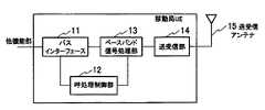
図1に、本実施形態に係る移動局UEの概要構成例を示す。図1に示すように、移動局UEは、バスインターフェース部11と、呼処理制御部12と、ベースバンド信号処理部13と、送受信部14と、送受信アンテナ15とを具備する。また、移動局UEは、アンプ部(図示せず)を具備するように構成されていてもよい。 FIG. 1 shows a schematic configuration example of a mobile station UE according to the present embodiment. As shown in FIG. 1, the mobile station UE includes a
ただし、これらの構成は、必ずしもハードウエアとして独立して存在している必要はない。すなわち、各構成が、合体していてもよいし、ソフトウエアのプロセスによって構成されていてもよい。 However, these configurations do not necessarily have to exist independently as hardware. That is, the components may be combined or may be configured by a software process.
図2に、ベースバンド信号処理部13の機能ブロックを示す。図2に示すように、ベースバンド信号処理部13は、上位レイヤ機能部131と、RLCサブレイヤとして機能するRLC機能部132と、MAC−d機能部133と、MAC−e機能部134と、レイヤ1として機能するレイヤ1機能部135とを具備している。 FIG. 2 shows functional blocks of the baseband
図3に示すように、RLC機能部132は、上位レイヤ機能部131から受信したアプリケーションデータ(RLC SDU)を、予め決められたPDUサイズに分割し、順序整理処理や再送処理等に用いるRLCヘッダを付与することによって、RLC PDUを生成して、MAC−d機能部133に渡す。 As shown in FIG. 3, the
ここで、RLC機能部132とMAC−d機能部133との間の橋渡しとして機能するパイプを「論理チャネル」とする。論理チャネルは、送受信するデータの内容によって分類され、通信を行う場合、1つのコネクションにおいて複数の論理チャネルを持つことが可能である。すなわち、複数の内容のデータ(例えば、制御データ及びユーザデータ等)を論理的に並列して送受信することができる。 Here, a pipe that functions as a bridge between the
MAC−d機能部133は、論理チャネルを多重し、かかる多重に伴うMAC−dヘッダを付与することによって、MAC−d PDUを生成する。なお、複数のMAC−d PDUは、MAC−dフローとして、MAC−d機能部133からMAC−e機能部134に転送されるものとする。 The MAC-d
MAC−e機能部134は、MAC−d機能部133からMAC−dフローとして受信した複数のMAC−d PDUをまとめてMAC−eヘッダを付与することによって、トランスポートブロックを生成し、生成したトランスポートブロックを、トランスポートチャネルを介してレイヤ1機能部135に渡す。 The MAC-
また、MAC−e機能部134は、MAC−d機能部133の下位レイヤとして機能するものであって、ハイブリッドARQ(HARQ)による再送制御機能や、伝送速度制御機能を行うものである。 The MAC-
具体的には、MAC−e機能部134は、図4に示すように、多重部134aと、E−TFC選択部134bと、HARQ処理部134cとを具備している。 Specifically, as illustrated in FIG. 4, the MAC-
多重部134aは、E−TFC選択部134bから通知されたE−TFI(Enhanced−Transport Format Indicator)に基づいて、MAC−d機能部133からMAC−dフローとして受信した上りユーザデータに対して多重化処理を行い、トランスポートチャネル(E−DCH)を介して送信すべき上りユーザデータ(トランスポートブロック)を生成して、HARQ処理部134cに送信するように構成されている。 The
以下、MAC−dフローとして受信した上りユーザデータを「上りユーザデータ(MAC−dフロー)」と示し、トランスポートチャネル(E−DCH)を介して送信すべき上りユーザデータを「上りユーザデータ(E−DCH)」と示す。 Hereinafter, the uplink user data received as the MAC-d flow is referred to as “uplink user data (MAC-d flow)”, and the uplink user data to be transmitted via the transport channel (E-DCH) is referred to as “uplink user data ( E-DCH) ".
ここで、E−TFIは、トランスポートチャネル(E−DCH)上でTTIごとにトランスポートブロックを供給するフォーマットであるトランスポートフォーマットの識別子であり、上述のMAC−eヘッダに付与されるものである。 Here, E-TFI is an identifier of a transport format that is a format for supplying a transport block for each TTI on the transport channel (E-DCH), and is given to the MAC-e header described above. is there.
また、多重部134aは、E−TFC選択部134bから通知されたE−TFIに基づいて、上りユーザデータに適用される送信データブロックサイズを判断して、HARQ処理部134cに通知するように構成されている。 Further, the
なお、多重部134aは、MAC−d機能部133からMAC−dフローとして上りユーザデータを受信した場合、当該上りユーザデータ用のトランスポートフォーマットを選択するためのE−TFC選択情報を、E−TFC選択部134bに通知するように構成されている。 When the
ここで、E−TFC選択情報には、上りユーザデータのデータサイズや優先度クラス等が該当する。 Here, the E-TFC selection information corresponds to the data size or priority class of the uplink user data.
HARQ処理部134cは、Nチャネルのストップアンドウェイト(N−SAW)プロトコルによって、レイヤ1機能部135から通知された上りユーザデータ用のACK/NACKに基づいて、上りユーザデータ(E−DCH)に係る再送制御処理を行うように構成されている。ここで、図5に、4チャネルのストップアンドウェイトプロトコルの動作例を示す。 The
また、HARQ処理部134cは、多重部134aから受信した上りユーザデータ(E−DCH)、及び、HARQ処理に用いられるHARQ情報(例えば、再送番号等)を、レイヤ1機能部135に送信するように構成されている。 Also, the
E−TFC選択部134bは、上りユーザデータ(E−DCH)に適用するトランスポートフォーマット(E−TF)を選択することによって、当該上りユーザデータの伝送速度を決定するように構成されている。 The
具体的には、E−TFC選択部134bは、無線基地局NodeBから受信したスケジューリング情報(例えば、上りユーザデータの絶対伝送速度や相対伝送速度)や、MAC−d機能部133から渡されたMAC−d PDUのデータ量(上りユーザデータのデータサイズ)や、MAC−e機能部134において管理されている無線基地局NodeBのハードウエアリソースの状態等に基づいて、上りユーザデータの送信実行又は送信停止を決定し、さらに、当該上りユーザデータの送信に適用されるトランスポートフォーマット(E−TF)を選択し、当該トランスポートフォーマットを識別するためのE−TFIをレイヤ1機能部135及び多重部134aに通知するように構成されている。 Specifically, the
例えば、E−TFC選択部134bは、上りユーザデータの伝送速度と、トランスポートフォーマットとを関連付けて記憶しており、レイヤ1機能部135からのスケジューリング情報に基づいて上りユーザデータの伝送速度を更新して、更新した上りユーザデータの伝送速度に関連付けられているトランスポートフォーマットを識別するためのE−TFIをレイヤ1機能部135及び多重部134aに通知するように構成されている。 For example, the
ここで、E−TFC選択部134bは、E−AGCHを介して、スケジューリング情報として、移動局UEのサービングセルからの上りユーザデータの絶対伝送速度を受信した場合、上りユーザデータの伝送速度を当該上りユーザデータの絶対伝送速度に変更する。 Here, when the
また、E−TFC選択部134bは、E−RGCHを介して、スケジューリング情報として、移動局UEの非サービングセルからの上りユーザデータの相対伝送速度(UPコマンド又はDOWNコマンド)を受信した場合、その時点における上りユーザデータの伝送速度を、上りユーザデータの相対伝送速度に基づいて予め決められている速度だけ増加又は減少させる。 In addition, when the
本明細書において、上りユーザデータの伝送速度は、E−DPDCH(Enhanced Dedicated Physical Data Channel)を介して上りユーザデータを送信可能な速度であってもよいし、上りユーザデータを送信するための送信データブロックサイズ(TBS)であってもよいし、E−DPDCHの送信電力であってもよいし、E−DPDCHとDPCCH(Dedicated Physical Control Channel)との送信電力比(送信電力オフセット)であってもよい。 In the present specification, the transmission rate of the uplink user data may be a rate at which the uplink user data can be transmitted via E-DPDCH (Enhanced Dedicated Physical Data Channel), or a transmission for transmitting the uplink user data. It may be a data block size (TBS), E-DPDCH transmission power, or a transmission power ratio (transmission power offset) between E-DPDCH and DPCCH (Dedicated Physical Control Channel). Also good.
図6に示すように、レイヤ1機能部135は、伝送チャネル符号化部135aと、物理チャネルマッピング部135bと、E−DPDCH送信部135cと、E−DPCCH送信部135dと、E−HICH受信部135eと、E−RGCH受信部135fと、E−AGCH受信部135gと、物理チャネルデマッピング部135hと、DCDCH送信部135iと、DPCH受信部135jとを具備している。 As shown in FIG. 6, the
伝送チャネル符号化部135aは、図7に示すように、FEC(Forward Error Collection)符号化部135a1と、伝送速度整合部135a2とを具備している。 As illustrated in FIG. 7, the transmission
図7に示すように、FEC符号化部135a1は、MAC−e機能部134から送信された上りユーザデータ(E−DCH)、すなわち、トランスポートブロックに対して、誤り訂正符号化処理を施すように構成されている。 As shown in FIG. 7, the FEC encoding unit 135a1 performs error correction encoding processing on the uplink user data (E-DCH) transmitted from the MAC-
また、図7に示すように、伝送速度整合部135a2は、誤り訂正符号化処理を施したトランスポートブロックに対して、物理チャネルの伝送容量に合わせるための「レペティション(ビット繰り返し)」や「パンクチャ(ビットの間引き)」を施すように構成されている。 Further, as shown in FIG. 7, the transmission rate matching unit 135a2 performs “repetition (bit repetition)” or “puncture” for adjusting the transmission capacity of the physical channel to the transport block subjected to the error correction coding process. (Thinning of bits) ".
物理チャネルマッピング部135bは、伝送チャネル符号化部135aからの上りユーザデータ(E−DCH)をE−DPDCHにマッピングし、伝送チャネル符号化部135aからのE−TFI及びHARQ情報をE−DPCCHにマッピングするように構成されている。 The physical
E−DPDCH送信部135Cは、上述のE−DPDCHについての送信処理を行うように構成されており、E−DPCCH送信部135dは、上述のE−DPCCHについての送信処理を行うように構成されている。 The E-DPDCH transmission unit 135C is configured to perform transmission processing for the above-described E-DPDCH, and the
E−HICH受信部135eは、セル(移動局UEのサービングセル及び非サービングセル)から送信されたE−HICH(E−DCH HARQ Acknowledgement Indicator Channel)の受信処理を行うように構成されている。 The E-HICH reception unit 135e is configured to perform reception processing of E-HICH (E-DCH HARQ Acknowledgment Indicator Channel) transmitted from a cell (serving cell and non-serving cell of the mobile station UE).
E−RGCH受信部135fは、セル(移動局UEのサービングセル及び非サービングセル)から送信されたE−RGCHの受信処理を行うように構成されている。 The
E−AGCH受信部135gは、セル(移動局UEのサービングセル)から送信されたE−AGCHの受信処理を行うように構成されている。 The
また、物理チャネルデマッピング部135hは、E−RGCH受信部135fにより受信されたE−RGCHに含まれるスケジューリング情報(上りユーザデータの相対伝送速度、すなわち、UPコマンド/DOWNコマンド)を抽出してMAC−e機能部134に送信するように構成されている。 Further, the physical
また、物理チャネルデマッピング部135hは、E−AGCH受信部135gにより受信されたE−AGCHに含まれるスケジューリング情報(上りユーザデータの絶対伝送速度)を抽出してMAC−e機能部134に送信するように構成されている。 Further, the physical
DCDCH送信部135iは、移動局UEによって送信される上りユーザデータを送信するための上り個別データ物理チャネル(DPDCH:Dedicated Physical Data Channel)についての送信処理を行うように構成されている。 The
かかる上りユーザデータには、セルから送信された共通パイロット信号の受信電力の測定報告(Measurement report)が含まれている。 The uplink user data includes a measurement report (Measurement report) of the reception power of the common pilot signal transmitted from the cell.
DPCH受信部135jは、セルから送信される下り個別物理チャネル(DPCH:Dedicated Physical Channel)についての受信処理を行うように構成されている。 The
ここで、上述した個別物理チャネル(DPCH)には、個別物理物理データチャネル(DPDCH:Dedicated Physical Data Channel)と、個別物理物理制御チャネル(DPDCH:Dedicated Physical Control Channel)とが含まれている。 Here, the above-described dedicated physical channel (DPCH) includes a dedicated physical physical data channel (DPDCH) and a dedicated physical physical control channel (DPDCH: Dedicated Physical Control Channel).
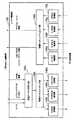
図8は、本実施形態に係る無線基地局NodeBの機能ブロック構成例である。図8に示すように、本実施形態に係る無線基地局NodeBは、HWYインターフェース21と、ベースバンド信号処理部22と、送受信部23と、アンプ部24と、呼処理制御部26と、送受信アンテナ25とを具備する。 FIG. 8 is a functional block configuration example of the radio base station NodeB according to the present embodiment. As shown in FIG. 8, the radio base station NodeB according to this embodiment includes an
HWYインターフェース21は、当該無線基地局NodeBの上位に位置する無線回線制御局RNCから、送信すべき下りユーザデータを受信して、ベースバンド信号処理部22に入力するように構成されている。また、HWYインターフェース21は、ベースバンド信号処理部22からの上りユーザデータを、無線回線制御局RNCに送信するように構成されている。 The
ベースバンド信号処理部22は、下りユーザデータに対してチャネル符号化処理や拡散処理等のレイヤ1処理を行った後、かかる下りユーザデータを含むベースバンド信号を送受信部23に送信するように構成されている。 The baseband
また、ベースバンド信号処理部22は、ベースバンド信号処理部22からのベースバンド信号に対して、逆拡散処理やRAKE合成処理や、誤り訂正復号化処理等のレイヤ1処理を行った後、取得した上りユーザデータをHWYインターフェース21に送信するように構成されている。 In addition, the baseband
送受信部23は、ベースバンド信号処理部22からのベースバンド信号を無線周波数帯信号に変換するように構成されている。また、送受信部23は、アンプ部24からの無線周波数帯信号をベースバンド信号に変換するように構成されている。 The transmission / reception unit 23 is configured to convert the baseband signal from the baseband
アンプ部24は、送受信部23からの無線周波数帯信号を増幅して、送受信アンテナ25を介して送信するように構成されている。また、アンプ部24は、送受信アンテナ25において受信された信号を増幅して送受信部23に送信するように構成されている。 The amplifier unit 24 is configured to amplify the radio frequency band signal from the transmission / reception unit 23 and transmit it via the transmission /
呼処理制御部26は、無線回線制御局RNCとの間で、呼処理制御信号の送受信を行い、当該無線基地局NodeBの各機能部の状態管理や、レイヤ3によるハードウエアリソース割り当て等の処理を行うように構成されている。 The call
図9は、ベースバンド信号処理部22の機能ブロック図である。図9に示すように、ベースバンド信号処理部22は、レイヤ1機能部221と、MAC−e機能部222とを具備している。 FIG. 9 is a functional block diagram of the baseband
図10に示すように、レイヤ1機能部221は、E−DPCCH逆拡散・RAKE合成部221aと、E−DPCCH復号部221bと、E−DPDCH逆拡散・RAKE合成部221cと、バッファ221dと、再逆拡散部221eと、HARQバッファ221fと、誤り訂正復号部221gと、伝送チャネル符号化部221hと、物理マッピング部221iと、E−HICH送信部221jと、E−AGCH送信部221kと、E−RGCH送信部221lと、DPDCH逆拡散・RAKE合成部221mと、DPDCH復号部221nと、DPCH送信部221oとを具備している。 As shown in FIG. 10, the
なお、これらの構成は、必ずしもハードウエアとして独立して存在している必要はない。すなわち、各構成が、合体していてもよいし、ソフトウエアのプロセスによって構成されていてもよい。 Note that these configurations do not necessarily have to exist independently as hardware. That is, the components may be combined or may be configured by a software process.
E−DPCCH逆拡散・RAKE部221aは、E−DPCCHに対して逆拡散処理及びRAKE合成処理を施すように構成されている。 The E-DPCCH despreading /
E−DPCCH復号部221bは、E−DPCCH逆拡散・RAKE部221aからの出力に基づいて、上りユーザデータの伝送速度を判定するためのE−TFCI(又は、E−TFRI:Enhanced Transport Format and Resource Indicator)を復号して、MAC−e機能部222に送信するように構成されている。 The
E−DPDCH逆拡散・RAKE合成部221cは、E−DPDCHに対して、E−DPDCHが取り得る最高レートに対応する拡散率(最小の拡散率)及びマルチコード数を用いて逆拡散処理を施して、バッファ221dに蓄積するように構成されている。かかる拡散率及びマルチコード数を用いて逆拡散処理を行うことによって、移動局UEが取り得る最高レート(ビットレート)まで受信できるようにリソースを確保することができる。 The E-DPDCH despreading /
再逆拡散部221eは、MAC−e機能部222から通知された拡散率及びマルチコード数を用いて、バッファ221dに記憶されているデータに対して再逆拡散処理を施して、HARQバッファ221fに蓄積するように構成されている。 The
誤り訂正復号部221gは、MAC−e機能部222から通知された符号化レートに基づいて、バッファ221dに記憶されているデータに対して誤り訂正復号処理を施すことによって取得した上りユーザデータ(E−DCH)をMAC−e機能部222に送信するように構成されている。 Based on the encoding rate notified from the MAC-
伝送チャネル符号化部221hは、MAC−e機能部222から受信した上りユーザデータ用のACK/NACK及びスケジューリング情報について、必要な符号化処理を施すように構成されている。 The transmission
物理チャネルマッピング部221iは、伝送チャネル符号化部221hからの上りユーザデータ用のACK/NACKをE−HICHにマッピングし、伝送チャネル符号化部221hからのスケジューリング情報(絶対伝送速度)をE−AGCHにマッピングし、伝送チャネル符号化部221hからのスケジューリング情報(相対伝送速度)をE−RGCHにマッピングするように構成されている。 The physical channel mapping unit 221i maps the ACK / NACK for uplink user data from the transmission
E−HICH送信部221jは、上述のE−HICHについての送信処理を行うように構成されている。 The E-HICH transmission unit 221j is configured to perform transmission processing for the above-described E-HICH.
E−AGCH送信部221kは、上述のE−AGCHについての送信処理を行うように構成されている。また、E−AGCH送信部221kは、スケジューリング部222cから通知される第1又は第2のE−AGCHオフセットと、下りDPCHの送信電力とに基づいて、E−AGCHの送信電力を決定し、決定した送信電力でE−AGCHを送信するように構成されている。 The
具体的には、DPCH送信部221oから下りDPCHの送信電力を取得し、当該DPCHの送信電力に対して、スケジューリング部222cから通知された第1又は第2のE−AGCHオフセットを乗算又は加算することで、E−AGCHの送信電力を決定するように構成されている。 Specifically, the downlink DPCH transmission power is acquired from the DPCH transmission unit 221o, and the transmission power of the DPCH is multiplied or added by the first or second E-AGCH offset notified from the
また、E−RGCH送信部221lは、上述のE−RGCHについての送信処理を行うように構成されている。 In addition, the E-RGCH transmission unit 221l is configured to perform transmission processing for the above-described E-RGCH.
DPDCH逆拡散・RAKE部221mは、DPDCHに対して逆拡散処理及びRAKE合成処理を施すように構成されている。 The DPDCH despreading /
DPPCH復号部221nは、DPCCH逆拡散・RAKE部221mからの出力に基づいて、移動局UEから送信された上りユーザデータを復号して、DCH(Dedicated Channel)を介してMAC−e機能部222に送信するように構成されている。 The
ここで、上述した上りユーザデータには、移動局UEから送信された共通パイロット信号の受信電力の測定報告(Measurement report)が含まれている。 Here, the uplink user data described above includes a measurement report (Measurement report) of the reception power of the common pilot signal transmitted from the mobile station UE.
DPCH送信部221oは、無線基地局NodeBから送信される下り個別物理チャネル(DPCH:Dedicated Physical Channel)についての送信処理を行うように構成されている。 The DPCH transmission unit 221o is configured to perform transmission processing for a downlink dedicated physical channel (DPCH) transmitted from the radio base station NodeB.
また、DPCH送信部221oは、下りDPCHの送信電力をE−AGCH送信部221kへ通知するように構成されている。 Further, the DPCH transmission unit 221o is configured to notify the transmission power of the downlink DPCH to the
図11に示すように、MAC−e機能部222は、HARQ処理部222aと、受信処理命令部222bと、スケジューリング部222cと、多重化解除部222dとを具備している。 As shown in FIG. 11, the MAC-
HARQ処理部222aは、レイヤ1機能部221から受信した上りユーザデータ(E−DCH)及びHARQ情報を受信して、当該上りユーザデータ(E−DCH)についてのHARQ処理を行うように構成されている。 The
また、HARQ処理部222aは、当該上りユーザデータ(E−DCH)についての受信処理結果を示すACK/NACK(上りユーザデータ用)をレイヤ1機能部221に通知するように構成されている。また、HARQ処理部222aは、プロセスごとのACK/NACK(上りユーザデータ用)をスケジューリング部222cに通知するように構成されている。 Further, the
受信処理命令部222bは、レイヤ1機能部221のE−DPCCH復号部221bから受信したTTIごとのE−TFCIによって特定された各移動局UEのトランスポートフォーマットに係る拡散率及びマルチコード数を再逆拡散部221e及びHARQバッファ221fに通知し、符号化レートを誤り訂正復号部221gに通知するように構成されている。 The reception
スケジューリング部222cは、レイヤ1機能部221のE−DPCCH復号部221bから受信したTTIごとのE−TFCIや、HARQ処理部222aから受信したプロセスごとのACK/NACKや、干渉レベル等に基づいて、上述の上りユーザデータの絶対伝送速度又は相対伝送速度を変更するように構成されている。 The
なお、スケジューリング部222cは、スケジューリング情報として、かかる上りユーザデータの絶対伝送速度又は相対伝送速度を、DCHを介してレイヤ1機能部221に通知するように構成されている。 The
また、スケジューリング部222cは、HWYインターフェースを介して、無線回線制御局RNCから送信されるE−AGCHオフセット情報を受信するように構成されている。 The
また、スケジューリング部222cは、E−AGCHオフセット情報に含まれる第1又は第2のE−AGCHオフセットを、DCHを介して、レイヤ1機能部221に通知するように構成されている。 The
多重化解除部222dは、HARQ処理部222aから受信した上りユーザデータ(E−DCH及びDCH)に対して多重化解除処理を施すことによって取得した上りユーザデータをHWYインターフェース21に送信するように構成されている。また、かかる上りユーザデータには、移動局UEから送信された共通パイロット信号の受信電力の測定報告(Measurement report)が含まれている。 The
本実施形態に係る無線回線制御局RNCは、無線基地局NodeBの上位に位置する装置であり、無線基地局NodeBと移動局UEとの間の無線通信を制御するように構成されている。 The radio network controller RNC according to the present embodiment is an apparatus positioned above the radio base station NodeB, and is configured to control radio communication between the radio base station NodeB and the mobile station UE.
図12に示すように、本実施形態に係る無線回線制御局RNCは、交換局インターフェース31と、LLCレイヤ処理部32と、MACレイヤ処理部33と、メディア信号処理部34と、無線基地局インターフェース35と、呼処理制御部36とを具備している。 As shown in FIG. 12, the radio network controller RNC according to the present embodiment includes an
交換局インターフェース31は、交換局1とのインターフェースである。交換局インターフェース31は、交換局1から送信された下りリンク信号をLLCレイヤ処理部32に転送し、LLCレイヤ処理部32から送信された上りリンク信号を交換局1に転送するように構成されている。 The
LLCレイヤ処理部32は、シーケンスパターン番号等のヘッダ又はトレーラの合成処理等のLLC(論理リンク制御:Logical Link Control)サブレイヤ処理を施すように構成されている。LLCレイヤ処理部32は、LLCサブレイヤ処理を施した後、上りリンク信号については交換局インターフェース31に送信し、下りリンク信号についてはMACレイヤ処理部33に送信するように構成されている。 The LLC
MACレイヤ処理部33は、優先制御処理やヘッダ付与処理等のMACレイヤ処理を施すように構成されている。MACレイヤ処理部33は、MACレイヤ処理を施した後、上りリンク信号についてはLLCレイヤ処理部32に送信し、下りリンク信号については無線基地局インターフェース35(又は、メディア信号処理部34)に送信するように構成されている。 The MAC
メディア信号処理部34は、音声信号やリアルタイムの画像信号に対して、メディア信号処理を施すように構成されている。メディア信号処理部34は、メディア信号処理を施した後、上りリンク信号についてはMACレイヤ処理部33に送信し、下りリンク信号については無線基地局インターフェース35に送信するように構成されている。 The media
無線基地局インターフェース35は、無線基地局NodeBとのインターフェースである。無線基地局インターフェース35は、無線基地局NodeBから送信された上りリンク信号をMACレイヤ処理部33(又は、メディア信号処理部34)に転送し、MACレイヤ処理部33(又は、メディア信号処理部34)から送信された下りリンク信号を無線基地局NodeBに転送するように構成されている。 The radio
呼処理制御部36は、無線リソース管理処理や、レイヤ3シグナリングによるチャネルの設定及び開放処理等を施すように構成されている。ここで、無線リソース管理には、呼受付制御やハンドオーバー制御等が含まれる。 The call
また、呼処理制御部36は、E−AGCHオフセット情報を、無線基地局インターフェース35を介して、無線基地局NodeBへ送信するように構成されている。 Further, the call
さらに、呼処理制御部36は、図12に示すように、E−AGCHとDPCHとの送信電力比を第1又は第2のE−AGCHオフセット37として記憶するように構成されている。 Furthermore, the call
また、呼処理制御部36は、移動局UEが、複数のセルとの間で無線リンクが設定されているSHO状態の場合、第2のE−AGCHオフセットを含む上述したE−AGCHオフセット情報を生成するように構成されている。 In addition, when the mobile station UE is in the SHO state in which radio links are set up with a plurality of cells, the call
また、移動局UEが、一つのセルとの間で無線リンクが設定されている非SHO状態の場合、第1のE−AGCHオフセットを含む上述したE−AGCHオフセット情報を生成するように構成されている。 Further, the mobile station UE is configured to generate the above-described E-AGCH offset information including the first E-AGCH offset when the mobile station UE is in a non-SHO state in which a radio link is established with one cell. ing.
また、本実施形態における無線リンクには、移動局UEとセルとの間のDPCH又はE−DPDCHが含まれる。よって、本実施形態では、移動局UEが、一つのセルとの間の無線リンクを設定した場合を非SHO状態とし、複数のセルとの間の無線リンクを設定した場合をSHO状態として以下に示す。 Further, the radio link in the present embodiment includes DPCH or E-DPDCH between the mobile station UE and the cell. Therefore, in this embodiment, the case where the mobile station UE sets a radio link with one cell is set as a non-SHO state, and the case where a radio link with a plurality of cells is set is set as an SHO state below. Show.
ここで、第1のE−AGCHオフセット及び第2のE−AGCHオフセットは、E−AGCHとDPCHとの送信電力比であり、第2のE−AGCHオフセットは、第1のE−AGCHオフセットよりも、大きくなるように設定されている。 Here, the first E-AGCH offset and the second E-AGCH offset are transmission power ratios of E-AGCH and DPCH, and the second E-AGCH offset is greater than the first E-AGCH offset. Is also set to be larger.
(本発明の第1の実施形態に係る移動通信システムの動作)
以下、図13及び図14参照して、本実施形態に係る移動通信システムの動作について説明する。具体的には、本実施形態に係る移動通信システムにおいて、上りユーザデータの絶対伝送速度制御チャネル(E−AGCH)の送信電力を制御する動作について説明する。(Operation of the mobile communication system according to the first embodiment of the present invention)
Hereinafter, the operation of the mobile communication system according to the present embodiment will be described with reference to FIG. 13 and FIG. Specifically, an operation for controlling the transmission power of the absolute transmission rate control channel (E-AGCH) of uplink user data in the mobile communication system according to the present embodiment will be described.
なお、本実施形態に係る無線基地局NodeBは、一つ又は複数のセルを管理するように構成されている。また、本実施形態に係る当該セルは、無線基地局NodeBの機能を具備する場合を例に説明する
また、図13及び図14におけるセル#10は、移動局UEのサービングセルであり、#20は移動局UEの非サービングセルである。したがって、移動局UEは、該セル#10から送信されたE−AGCHに基づいて、上りユーザデータの送信速度を制御するように構成されている。Note that the radio base station NodeB according to the present embodiment is configured to manage one or a plurality of cells. Further, the case where the cell according to the present embodiment has the function of the radio base station NodeB will be described as an example. Also,
また、本実施形態におけるセル#10及びセル#20は、同一の無線基地局NodeBに管理されるように構成されていてもよいし、セル#10とセル#20とで、異なる無線基地局NodeBによって管理されるように構成されていてもよい。 Further, the
第1に、移動局UEが、セル#10とのみ無線リンクが設定されている状態(非SHO状態)から、セル#10及びセル#20との無線リンクが設定されている状態(SHO状態)に遷移する場合を例に、セル#10がE−HICHの送信電力を制御する動作を示す。 First, the mobile station UE is in a state (SHO state) where a radio link is set with the
図13に示すように、ステップS1001において、移動局UEは、#10を介して、上りユーザデータを送信するためのデータコネクション(E−DPDCH)を無線回線制御局RNCと確立している。 As shown in FIG. 13, in step S1001, the mobile station UE establishes a data connection (E-DPDCH) for transmitting uplink user data with the radio network controller RNC via # 10.
かかる場合、セル#10は、下りDPCHの送信電力と、第1のE−AGCHオフセットとに基づいて、E−AGCHの送信電力を決定する。 In this case, the
具体的には、セル#10は、閉ループ送信電力制御された下りDPCHの送信電力に対して、予め記憶している所定の第1のE−AGCHオフセットを乗算又は加算することで、E−AGCHの送信電力を決定するように構成されている。 Specifically, the
ステップS1002において、移動局UEは、セル#20からの共通パイロット信号の受信電力が、所定の値以上になった場合、測定報告(Measurement report)を無線回線制御局RNCに送信する。 In step S1002, the mobile station UE transmits a measurement report (Measurement report) to the radio network controller RNC when the reception power of the common pilot signal from the cell # 20 becomes a predetermined value or more.
ステップS1003において、無線回線制御局RNCは、当該測定報告に基づいて、セル#20を管理する無線基地局NodeB#2に対して、移動局UEとセル#20との間の上り無線リンクを同期するように要求する。 In step S1003, the radio network controller RNC synchronizes the uplink radio link between the mobile station UE and the cell # 20 to the radio base station
具体的には、無線回線制御局RNCは、セル#20を管理する無線基地局NodeB#2に対して、上り無線リンクにおけるチャネル構成を識別するチャネライゼーションコードと、移動局UEを識別するスクランブリングコードとを含むSHO設定要求を送信することによって、移動局UEとセル#20との間の上り無線リンクを同期するように要求する。Specifically, the radio network controller RNC, with respect to the radio base
ステップS1004において、セル#20を管理する無線基地局NodeB#2は、移動局UEとセル#20との間の上り無線リンクの同期を確立する。 In step S1004, the radio base
具体的には、セル#20を管理する無線基地局NodeB#2は、無線回線制御局RNCから受信したチャネライゼーションコードとスクランブリングコードとを用いて、上り無線リンクにおいて、移動局UEから送信されているチャネルを検出することによって、移動局UEとセル#20との間の上り無線リンクの同期を確立する。当該移動局UEとセル#20との間の上り無線リンクの同期が確立された場合、セル#20を管理する無線基地局NodeB#2は、無線回線制御局RNCへSHO設定応答を送信する。また、セル#20は、当該移動局UEに対して、下り無線リンクにおいて、DPCH等の送信を開始する。 Specifically, the radio base
ステップS1005において、無線回線制御局RNCは、移動局UEに対して、セル#20と移動局UEとの間の下り無線リンクを同期するように要求する。 In step S1005, the radio network controller RNC requests the mobile station UE to synchronize the downlink radio link between the cell # 20 and the mobile station UE.
具体的には、無線回線制御局RNCは、移動局UEに対して、下り無線リンクにおけるチャネル構成を識別するチャネライゼーションコードと、セル#20を識別するスクランブリングコードとを含むSHO設定要求を送信することによって、セル#20と移動局UEとの間の下り無線リンクを同期するように要求する。 Specifically, the radio network controller RNC transmits an SHO setting request including a channelization code for identifying the channel configuration in the downlink radio link and a scrambling code for identifying cell # 20 to the mobile station UE. To request to synchronize the downlink radio link between the cell # 20 and the mobile station UE.
ステップS1006において、移動局UEは、セル#20と移動局UEとの間の下り無線リンクの同期を確立する。 In step S1006, the mobile station UE establishes downlink radio link synchronization between the cell # 20 and the mobile station UE.
具体的には、移動局UEは、無線回線制御局RNCから受信したチャネライゼーションコードとスクランブリングコードとを用いて、下り無線リンクにおける、セル#20からのチャネルを検出することによって、セル#20と移動局UEとの間の下り無線リンクの同期を確立する。当該セル#20と移動局UEとの間の下り無線リンクの同期が確立された場合、移動局UEは、SHO設定応答を無線回線制御局RNC送信する。 Specifically, the mobile station UE uses the channelization code and scrambling code received from the radio network controller RNC to detect the channel from the cell # 20 in the downlink radio link, thereby detecting the cell # 20. And establishes downlink radio link synchronization between the mobile station UE and the mobile station UE. When synchronization of the downlink radio link between the cell # 20 and the mobile station UE is established, the mobile station UE transmits an SHO setting response to the radio network controller RNC.
ステップS1007において、無線回線制御局RNCは、セル#10(サービングセル)を管理する無線基地局NodeB#1へ、第2のAGCHオフセットを含むE−AGCHオフセット情報を送信する。 In step S1007, the radio network controller RNC transmits E-AGCH offset information including the second AGCH offset to the radio base station
ステップS1008において、セル#10は、無線回線制御局RNCから送信されたE−AGCHオフセット情報に含まれる第2のE−AGCHオフセットに基づいて、E−AGCHの送信電力を決定する。 In step S1008, the
ここで、無線回線制御局RNCから送信される第2のE−AGCHオフセットは、第1のAGCHオフセットよりも大きい。したがって、セル#10は、E−AGCHの送信先である移動局UEがSHO状態である場合、E−AGCHオフセットを大きくし、E−AGCHの送信電力を強くすることにより、E−AGCHをSHO状態の移動局UEへ、より確実に到達させることができる。 Here, the second E-AGCH offset transmitted from the radio network controller RNC is larger than the first AGCH offset. Therefore, when the mobile station UE that is the transmission destination of E-AGCH is in the SHO state, the
第2に、移動局UEが、セル#10及びセル#20との間の無線リンクが設定されているSHO状態からセル#10とのみ無線リンクが設定されている非SHO状態に遷移し、セル#10がE−AGCHの送信電力を制御する動作を示す。 Second, the mobile station UE transitions from the SHO state in which the radio link between the
図14に示すように、ステップS2001において、移動局UEが、セル#20からの共通パイロット信号の受信電力が、所定の値未満となった場合、測定報告(Measurement report)を無線回線制御局RNCに送信する。 As shown in FIG. 14, in step S2001, when the reception power of the common pilot signal from the cell # 20 becomes less than a predetermined value, the mobile station UE sends a measurement report (Measurement report) to the radio network controller RNC. Send to.
ステップS2002において、無線回線制御局RNCは、当該測定報告に基づいて、セル#20を管理する無線基地局NodeB#2に対して、移動局UEとセル#20との間の上り無線リンクの設定を停止するように要求する。また、無線回線制御局RNCは、移動局UEに対して、SHO解除要求を送信し、セル#20と移動局UEとの間の下り無線リンクの設定を停止するように要求する。 In step S2002, the radio network controller RNC sets up an uplink radio link between the mobile station UE and the cell # 20 with respect to the radio base station
ステップS2003において、無線回線制御局RNCは、第1のE−AGCHオフセットを含むE−AGCHオフセット情報を、無線基地局NodeB#1へ送信する。 In step S2003, the radio network controller RNC transmits E-AGCH offset information including the first E-AGCH offset to the radio base
ステップS2004において、E−AGCHオフセット情報を受信したセル#10は、E−AGCHオフセットに含まれる第1のE−AGCHオフセットと、下りDPCHの送信電力とに基づいて、E−AGCHの送信電力を決定する。 In step S2004, the
このように、セル#10は、E−AGCHの送信先である移動局UEが非SHO状態である場合、非SHO状態におけるE−AGCHオフセットを適切に小さくし、E−AGCHの送信電力を調整することによって、無線回線容量を有効に使用する。 In this way, when the mobile station UE that is the transmission destination of E-AGCH is in the non-SHO state,
なお、本実施形態にかかる移動通信システムでは、無線回線制御局RNCは、移動局UEがSHO状態の際に、第2のE−AGCHオフセットを含むE−AGCHオフセット情報を送信する場合を例に示したが、移動局UEやセルからの所定の通知(例えば移動局UEからの所定のMeasurement report等)に基づいて、第2のE−AGCHオフセットを含むE−AGCHオフセット情報を送信するように構成されていても良い。 Note that, in the mobile communication system according to the present embodiment, the radio network controller RNC transmits an example of transmitting E-AGCH offset information including the second E-AGCH offset when the mobile station UE is in the SHO state. As shown, based on a predetermined notification from the mobile station UE or cell (for example, a predetermined measurement report from the mobile station UE), the E-AGCH offset information including the second E-AGCH offset is transmitted. It may be configured.
(本発明の第1の実施形態に係る移動通信システムの作用・効果)
以上説明したように、本発明に係る送信電力制御方法及び移動通信システムによれば、移動局UEがSHO状態の場合には、セル又はセルを管理する無線基地局NodeBは、E−AGCHオフセットを大きくし、E−AGCHの送信電力を大きくすることができるので、E−HICHを移動局UEに確実に到達させることができる。(Operations and effects of the mobile communication system according to the first embodiment of the present invention)
As described above, according to the transmission power control method and the mobile communication system according to the present invention, when the mobile station UE is in the SHO state, the radio base station NodeB that manages the cell sets the E-AGCH offset. Since the transmission power of E-AGCH can be increased, the E-HICH can surely reach the mobile station UE.
1…移動局UE、11…バスインターフェース部、12…呼処理制御部、13…ベースバンド信号処理部、131…上位レイヤ機能部、132…RLC機能部、133…MAC−d機能部、134…MAC−e機能部、134a…多重部、134b…E−TFC選択部、134c…HARQ処理部、135…レイヤ1機能部、135a…伝送チャネル符号化部、135b…物理チャネルマッピング部、135c…E−DPDCH送信部、135d…E−DPCCH送信部、135e…E−HICH受信部、135f…E−RGCH受信部、135g…E−AGCH受信部、135h…物理チャネルデマッピング部、135i…DPDCH送信部、135j…DPDCH受信部、14…送受信部、15…送受信アンテナ、2…無線基地局NodeB、21…HWYインターフェース、22…ベースバンド信号処理部、221…レイヤ1機能部、221a…E−DPCCH逆拡散・RAKE合成部、221b…E−DPCCH復号部、221c…E−DPDCH逆拡散・RAKE合成部、221d…バッファ、221e…再逆拡散部、221f…HARQバッファ、221g…誤り訂正復号部、221h…伝送チャネル符号化部、221i…物理チャネルマッピング部、221j…E−HICH送信部、221k…E−AGCH送信部、221l…E−RGCH送信部、221m…DPDCH逆拡散・RAKE合成部、221n…DPDCH復号部、221o…DPCH送信部、222…MAC−e機能部、222a…HARQ処理部、222b…受信処理命令部、222c…スケジューリング部、222d…多重化解除部、23…送受信部、24…アンプ部、25…送受信アンテナ、26…呼処理制御部、31…交換局インターフェース、32…LLCレイヤ処理部、33…MACレイヤ処理部、34…メディア信号処理部、35…無線基地局インターフェース、36…呼処理制御部 DESCRIPTION OF
Claims (3)
Translated fromJapanese前記移動局が、サービングセル及び非サービングセルとソフトハンドオーバー状態である場合、無線回線制御局が、前記絶対伝送速度制御チャネルの送信電力と個別物理チャネルの送信電力とのオフセットを、前記サービングセルを管理する前記無線基地局へ通知する工程と、
前記オフセットを通知された前記サービングセルが、前記オフセットに基づいて、前記絶対伝送速度制御チャネルの送信電力を決定する工程と、
前記サービングセルが、決定した送信電力で前記絶対伝送速度制御チャネルを前記移動局へ送信する工程とを有することを特徴とする送信電力制御方法。A transmission power control method for controlling transmission power of an absolute transmission rate control channel including an absolute transmission rate of uplink user data transmitted to a mobile station by a cell managed by a radio base station,
When the mobile station is in a soft handover state with a serving cell and a non-serving cell, the radio network controller manages the serving cell with an offset between the transmission power of the absolute transmission rate control channel and the transmission power of the dedicated physical channel. Notifying the radio base station;
The serving cell notified of the offset determines the transmission power of the absolute transmission rate control channel based on the offset;
And a step of transmitting the absolute transmission rate control channel to the mobile station by the serving cell with the determined transmission power.
前記移動局が、サービングセル及び非サービングセルとソフトハンドオーバー状態である場合、
無線回線制御局は、絶対伝送速度制御チャネルの送信電力と個別物理チャネルの送信電力とのオフセットを、サービングセルを管理する無線基地局へ通知するように構成され、
前記サービングセルは、通知された前記オフセットに基づいて、絶対伝送速度制御チャネルの送信電力を決定し、決定した送信電力で絶対伝送速度制御チャネルを前記移動局へ送信するように構成されていることを特徴とする移動通信システム。A mobile communication system for controlling transmission power of an absolute transmission rate control channel including an absolute transmission rate of uplink user data transmitted to a mobile station by a cell managed by a radio base station,
When the mobile station is in a soft handover state with a serving cell and a non-serving cell,
The radio network controller is configured to notify the radio base station that manages the serving cell of the offset between the transmission power of the absolute transmission rate control channel and the transmission power of the dedicated physical channel,
The serving cell is configured to determine the transmission power of the absolute transmission rate control channel based on the notified offset, and to transmit the absolute transmission rate control channel to the mobile station with the determined transmission power. A mobile communication system.
Priority Applications (18)
| Application Number | Priority Date | Filing Date | Title |
|---|---|---|---|
| JP2005274650AJP4592547B2 (en) | 2005-08-24 | 2005-08-24 | Transmission power control method and mobile communication system |
| US11/506,864US8750916B2 (en) | 2005-08-24 | 2006-08-21 | Transmission power control method, and mobile communication system |
| RU2006130462ARU2326511C1 (en) | 2005-08-24 | 2006-08-23 | Method of transmission power control and mobile communication system |
| BRPI0605796-9ABRPI0605796A (en) | 2005-08-24 | 2006-08-23 | Transmission power control method and mobile communication system |
| CNB2006101256082ACN100574141C (en) | 2005-08-24 | 2006-08-24 | Transmission power control method and mobile communication system |
| TW095131182ATWI349495B (en) | 2005-08-24 | 2006-08-24 | Transmission power control method, and mobile communication system |
| AT08011281TATE547914T1 (en) | 2005-08-24 | 2006-08-24 | METHOD FOR CONTROLLING A TRANSMISSION POWER AND MOBILE COMMUNICATION SYSTEM |
| AT06017689TATE487349T1 (en) | 2005-08-24 | 2006-08-24 | POWER CONTROL METHOD AND MOBILE COMMUNICATION SYSTEM |
| EP20080011281EP1968207B1 (en) | 2005-08-24 | 2006-08-24 | Transmission power control method, and mobile communication system |
| EP20060017689EP1758264B1 (en) | 2005-08-24 | 2006-08-24 | Transmission power control method and mobile communication system |
| ES06017689TES2355046T3 (en) | 2005-08-24 | 2006-08-24 | TRANSMISSION POWER CONTROL PROCEDURE AND MOBILE COMMUNICATION SYSTEM. |
| ES08011281TES2382586T3 (en) | 2005-08-24 | 2006-08-24 | Transmission power control procedure and mobile communication system |
| CN2009101636009ACN101657009B (en) | 2005-08-24 | 2006-08-24 | Transmission power control method and mobile communication system |
| EP07019923.7AEP1871014B1 (en) | 2005-08-24 | 2006-08-24 | Transmission power control method, and mobile communication system |
| DE200660017935DE602006017935D1 (en) | 2005-08-24 | 2006-08-24 | Power control method and mobile communication system |
| TW100120701ATWI469667B (en) | 2005-08-24 | 2006-08-24 | Transmission power control method, and mobile communication system |
| KR1020070077163AKR101138326B1 (en) | 2005-08-24 | 2007-07-31 | Transmission power control method, and mobile communication system |
| RU2008101682ARU2368080C1 (en) | 2005-08-24 | 2008-01-15 | Method for transmission power control and system of mobile communication |
Applications Claiming Priority (1)
| Application Number | Priority Date | Filing Date | Title |
|---|---|---|---|
| JP2005274650AJP4592547B2 (en) | 2005-08-24 | 2005-08-24 | Transmission power control method and mobile communication system |
Publications (2)
| Publication Number | Publication Date |
|---|---|
| JP2007060601A JP2007060601A (en) | 2007-03-08 |
| JP4592547B2true JP4592547B2 (en) | 2010-12-01 |
Family
ID=37452581
Family Applications (1)
| Application Number | Title | Priority Date | Filing Date |
|---|---|---|---|
| JP2005274650AExpired - Fee RelatedJP4592547B2 (en) | 2005-08-24 | 2005-08-24 | Transmission power control method and mobile communication system |
Country Status (11)
| Country | Link |
|---|---|
| US (1) | US8750916B2 (en) |
| EP (3) | EP1871014B1 (en) |
| JP (1) | JP4592547B2 (en) |
| KR (1) | KR101138326B1 (en) |
| CN (2) | CN100574141C (en) |
| AT (2) | ATE547914T1 (en) |
| BR (1) | BRPI0605796A (en) |
| DE (1) | DE602006017935D1 (en) |
| ES (2) | ES2355046T3 (en) |
| RU (2) | RU2326511C1 (en) |
| TW (2) | TWI469667B (en) |
Cited By (1)
| Publication number | Priority date | Publication date | Assignee | Title |
|---|---|---|---|---|
| US10833832B2 (en) | 2016-06-22 | 2020-11-10 | Intel Corporation | Communication device and a method for full duplex scheduling |
Families Citing this family (24)
| Publication number | Priority date | Publication date | Assignee | Title |
|---|---|---|---|---|
| CN101964701B (en) | 2003-08-25 | 2012-10-31 | 美商内数位科技公司 | Method, Node-B and WTRU for operating H-ARQ |
| US7046648B2 (en) | 2003-11-05 | 2006-05-16 | Interdigital Technology Corporation | Wireless communication method and apparatus for coordinating Node-B's and supporting enhanced uplink transmissions during handover |
| US7885245B2 (en)* | 2004-07-19 | 2011-02-08 | Interdigital Technology Corporation | Method and apparatus for enhanced uplink multiplexing |
| US8493941B2 (en)* | 2006-04-21 | 2013-07-23 | Alcatel Lucent | Method to control the effects of out-of-cell interference in a wireless cellular system using over-the-air feedback control |
| US8274952B2 (en)* | 2006-10-10 | 2012-09-25 | Alcatel Lucent | Transmission power management |
| CN101431797B (en) | 2007-05-11 | 2012-02-01 | 华为技术有限公司 | A registration processing method, system and device |
| CN101431351B (en)* | 2007-11-07 | 2013-05-08 | 中兴通讯股份有限公司 | Method for node B acquiring available power of scheduling reinforced special channel |
| CN101431793B (en)* | 2007-11-08 | 2011-03-02 | 中兴通讯股份有限公司 | Method for acquiring scheduling enhanced dedicated channel load in mixed time slot |
| CN102017712B (en)* | 2007-12-06 | 2015-01-21 | 艾利森电话股份有限公司 | Method and apparatus for power control during soft handover |
| BRPI0722251B1 (en)* | 2007-12-10 | 2020-01-21 | Zte Corp | method for configuring the absolute grant mapping table for radio network bypass controller |
| RU2447615C2 (en)* | 2007-12-10 | 2012-04-10 | ЗетТиИ Корпорейшн | Configuration method for absolute grant translation table for base station |
| CN101803422B (en)* | 2007-12-10 | 2013-08-21 | 中兴通讯股份有限公司 | The method of configuring the absolute authorization mapping relationship table for the base station |
| JP4937152B2 (en)* | 2008-02-01 | 2012-05-23 | 株式会社エヌ・ティ・ティ・ドコモ | Mobile communication method, mobile communication system, and radio base station |
| CN102695282B (en)* | 2008-08-12 | 2015-04-29 | 华为技术有限公司 | Method, device and system for scheduling radio resources |
| CN101651897B (en)* | 2008-08-12 | 2012-05-23 | 华为技术有限公司 | Method, device and system for radio resource scheduling |
| US8611941B2 (en)* | 2008-08-18 | 2013-12-17 | Qualcomm Incorporated | System and method for processing power control commands in a wireless communication system |
| WO2011040995A1 (en)* | 2009-09-30 | 2011-04-07 | Qualcomm Incorporated | Method and apparatus for closed loop power control during td-scdma baton handover |
| CN102076093B (en)* | 2009-11-24 | 2014-09-10 | 中兴通讯股份有限公司 | Downlink service admission control method and device |
| RU2549190C2 (en)* | 2010-04-30 | 2015-04-20 | Панасоник Интеллекчуал Проперти Корпорэйшн оф Америка | Wireless communication device and transmission power control method |
| CN103079592B (en)* | 2010-07-01 | 2015-10-21 | 浦项工科大学校产学协力团 | Methods of treating and diagnosing cancer using microvesicles derived from cells |
| US8958331B2 (en) | 2012-07-02 | 2015-02-17 | Intel Corporation | HARQ-ACK handling for unintended downlink sub-frames |
| TWI473462B (en)* | 2012-07-09 | 2015-02-11 | Ind Tech Res Inst | Method for performing hybrid automatic repeat request, base station and mobile device thereof |
| CN103546254B (en) | 2012-07-09 | 2017-09-15 | 财团法人工业技术研究院 | Method for performing hybrid automatic repeat request, and base station and mobile device thereof |
| EP3641414A4 (en)* | 2017-06-15 | 2020-06-17 | Fujitsu Limited | BASE STATION DEVICE, TERMINAL DEVICE, WIRELESS COMMUNICATION SYSTEM AND COMMUNICATION METHOD |
Family Cites Families (32)
| Publication number | Priority date | Publication date | Assignee | Title |
|---|---|---|---|---|
| US5267261A (en)* | 1992-03-05 | 1993-11-30 | Qualcomm Incorporated | Mobile station assisted soft handoff in a CDMA cellular communications system |
| KR960000147B1 (en)* | 1992-11-05 | 1996-01-03 | 삼성전자주식회사 | Cellular telephone |
| US6173162B1 (en)* | 1997-06-16 | 2001-01-09 | Telefonaktiebolaget Lm Ericsson (Publ) | Multiple code channel power control in a radio communication system |
| US6963750B1 (en)* | 1998-09-30 | 2005-11-08 | Lucent Technologies Inc. | CDMA power control for paging and initial traffic channel power |
| GB2359460A (en)* | 2000-02-18 | 2001-08-22 | Motorola Inc | Relating uplink measurements to a specific subscriber unit of an identified cell in a cellular communication system |
| US6650905B1 (en)* | 2000-06-30 | 2003-11-18 | Nokia Mobile Phones, Ltd. | Universal mobile telecommunications system (UMTS) terrestrial radio access (UTRA) frequency division duplex (FDD) downlink shared channel (DSCH) power control in soft handover |
| RU2258310C2 (en)* | 2000-10-04 | 2005-08-10 | Самсунг Электроникс Ко., Лтд. | Device and method for controlling power of shared direct communications channel in mobile communication system |
| KR100735402B1 (en)* | 2000-11-07 | 2007-07-04 | 삼성전자주식회사 | Apparatus and Method of Transmission Transmit Format Combination Indicator for Downlink Shared Channel in Asynchronous Mobile Communication System |
| US7190964B2 (en)* | 2001-08-20 | 2007-03-13 | Telefonaktiebolaget Lm Ericsson (Publ) | Reverse link power control in 1xEV-DV systems |
| KR100459573B1 (en)* | 2001-08-25 | 2004-12-03 | 삼성전자주식회사 | Apparatus for transmitting/receiving uplink transmission power and high speed downlink shared channel power level in communication system using high speed downlink packet access scheme and method thereof |
| AU2002358319B2 (en)* | 2001-11-16 | 2005-12-22 | Lg Electronics Inc. | Method for transmitting power control information for HS-SCCH in mobile communication system |
| KR100832117B1 (en)* | 2002-02-17 | 2008-05-27 | 삼성전자주식회사 | Apparatus and method for transmitting and receiving reverse transmission power offset information in mobile communication system using high speed forward packet access method |
| KR100891816B1 (en)* | 2002-05-11 | 2009-04-07 | 삼성전자주식회사 | A method of transmitting power offset information of high speed forward physical shared channel in asynchronous code division multiple access mobile communication system |
| CN100342673C (en)* | 2002-06-26 | 2007-10-10 | 华为技术有限公司 | Downgoing power control method in CDMA mobile communication system |
| JP2004032640A (en)* | 2002-06-28 | 2004-01-29 | Matsushita Electric Ind Co Ltd | Transmission power control method, communication terminal device and base station device |
| JP4022106B2 (en)* | 2002-06-28 | 2007-12-12 | 松下電器産業株式会社 | Signaling method and base station apparatus |
| JP3574443B2 (en)* | 2002-08-20 | 2004-10-06 | 松下電器産業株式会社 | Communication terminal device, base station device, and transmission power control method |
| GB2402021A (en)* | 2003-05-19 | 2004-11-24 | Nec Corp | Rate control method and apparatus for data packet transmission from a mobile phone to a base station |
| EP1526652A1 (en)* | 2003-10-24 | 2005-04-27 | Evolium S.A.S. | A method for setting a power offset for power control of a downlink shared channel in a mobile radiocommunication system |
| US20050237932A1 (en)* | 2004-04-23 | 2005-10-27 | Jung-Tao Liu | Method and system for rate-controlled mode wireless communications |
| US7454173B2 (en)* | 2004-04-23 | 2008-11-18 | Telefonaktiebolaget L M Ericsson (Publ) | Load control in shared medium many-to-one communication systems |
| EP2753007B1 (en)* | 2004-06-17 | 2017-07-26 | NEC Corporation | Transmission power control method of uplink packet data transmission |
| KR200368998Y1 (en) | 2004-09-09 | 2004-12-03 | 파츠닉(주) | Saturation vessel for manufacturing condenser |
| US7693110B2 (en)* | 2004-09-16 | 2010-04-06 | Motorola, Inc. | System and method for downlink signaling for high speed uplink packet access |
| US7961752B2 (en)* | 2004-12-22 | 2011-06-14 | Telefonaktiebolaget L M Ericsson (Publ) | Transmission in a shared medium having different access modes |
| US7724656B2 (en)* | 2005-01-14 | 2010-05-25 | Telefonaktiebolaget Lm Ericsson (Publ) | Uplink congestion detection and control between nodes in a radio access network |
| US7995585B2 (en)* | 2005-01-14 | 2011-08-09 | Alcatel Lucent | Method of controlling transmission rates |
| WO2006082627A1 (en)* | 2005-02-01 | 2006-08-10 | Mitsubishi Denki Kabushiki Kaisha | Transmission control method, mobile station and communication system |
| US8526357B2 (en)* | 2005-02-07 | 2013-09-03 | Telefonaktiebolaget Lm Ericsson (Publ) | Methods and arrangements for handling unreliable scheduling grants in a telecommunication network |
| US7701844B2 (en) | 2005-02-09 | 2010-04-20 | Interdigital Technology Corporation | Method and apparatus for recognizing radio link failures associated with HSUPA and HSDPA channels |
| US20060281417A1 (en)* | 2005-05-10 | 2006-12-14 | Ntt Docomo, Inc. | Transmission rate control method and mobile station |
| ES2361211T3 (en)* | 2007-11-26 | 2011-06-15 | Telefonaktiebolaget Lm Ericsson (Publ) | DPCCH AND HS-DPCCH CONTROL AT LOW CONCESSIONS FOR E-DCH. |
- 2005
- 2005-08-24JPJP2005274650Apatent/JP4592547B2/ennot_activeExpired - Fee Related
- 2006
- 2006-08-21USUS11/506,864patent/US8750916B2/enactiveActive
- 2006-08-23BRBRPI0605796-9Apatent/BRPI0605796A/ennot_activeIP Right Cessation
- 2006-08-23RURU2006130462Apatent/RU2326511C1/enactive
- 2006-08-24CNCNB2006101256082Apatent/CN100574141C/ennot_activeExpired - Fee Related
- 2006-08-24ESES06017689Tpatent/ES2355046T3/enactiveActive
- 2006-08-24EPEP07019923.7Apatent/EP1871014B1/ennot_activeNot-in-force
- 2006-08-24ESES08011281Tpatent/ES2382586T3/enactiveActive
- 2006-08-24ATAT08011281Tpatent/ATE547914T1/enactive
- 2006-08-24TWTW100120701Apatent/TWI469667B/enactive
- 2006-08-24DEDE200660017935patent/DE602006017935D1/enactiveActive
- 2006-08-24TWTW095131182Apatent/TWI349495B/ennot_activeIP Right Cessation
- 2006-08-24CNCN2009101636009Apatent/CN101657009B/ennot_activeExpired - Fee Related
- 2006-08-24EPEP20060017689patent/EP1758264B1/ennot_activeNot-in-force
- 2006-08-24EPEP20080011281patent/EP1968207B1/ennot_activeNot-in-force
- 2006-08-24ATAT06017689Tpatent/ATE487349T1/ennot_activeIP Right Cessation
- 2007
- 2007-07-31KRKR1020070077163Apatent/KR101138326B1/enactiveActive
- 2008
- 2008-01-15RURU2008101682Apatent/RU2368080C1/enactive
Cited By (1)
| Publication number | Priority date | Publication date | Assignee | Title |
|---|---|---|---|---|
| US10833832B2 (en) | 2016-06-22 | 2020-11-10 | Intel Corporation | Communication device and a method for full duplex scheduling |
Also Published As
| Publication number | Publication date |
|---|---|
| CN1921336A (en) | 2007-02-28 |
| TW201218821A (en) | 2012-05-01 |
| ATE547914T1 (en) | 2012-03-15 |
| JP2007060601A (en) | 2007-03-08 |
| CN101657009A (en) | 2010-02-24 |
| EP1871014B1 (en) | 2016-05-04 |
| KR101138326B1 (en) | 2012-04-25 |
| EP1968207B1 (en) | 2012-02-29 |
| EP1758264B1 (en) | 2010-11-03 |
| EP1968207A2 (en) | 2008-09-10 |
| CN101657009B (en) | 2012-10-10 |
| RU2006130462A (en) | 2008-02-27 |
| RU2326511C1 (en) | 2008-06-10 |
| US8750916B2 (en) | 2014-06-10 |
| EP1871014A3 (en) | 2008-01-23 |
| ES2355046T3 (en) | 2011-03-22 |
| EP1871014A2 (en) | 2007-12-26 |
| ES2382586T3 (en) | 2012-06-11 |
| EP1968207A3 (en) | 2010-01-20 |
| US20070047501A1 (en) | 2007-03-01 |
| ATE487349T1 (en) | 2010-11-15 |
| BRPI0605796A (en) | 2007-04-27 |
| TWI469667B (en) | 2015-01-11 |
| RU2368080C1 (en) | 2009-09-20 |
| DE602006017935D1 (en) | 2010-12-16 |
| EP1758264A2 (en) | 2007-02-28 |
| TW200718251A (en) | 2007-05-01 |
| KR20070083229A (en) | 2007-08-23 |
| TWI349495B (en) | 2011-09-21 |
| EP1758264A3 (en) | 2007-03-21 |
| CN100574141C (en) | 2009-12-23 |
Similar Documents
| Publication | Publication Date | Title |
|---|---|---|
| JP4592547B2 (en) | Transmission power control method and mobile communication system | |
| KR101151369B1 (en) | Transmission power control method, and mobile communication system | |
| KR101106082B1 (en) | Transmission power control method and mobile communication system | |
| KR101071624B1 (en) | Transmission power control method, and radio network controller | |
| JP4668733B2 (en) | Transmission rate control method and mobile station | |
| KR101186900B1 (en) | User data transmission method, and radio network controller | |
| JP4684062B2 (en) | Transmission rate control method and radio network controller | |
| JP4751673B2 (en) | Transmission rate control method and mobile station | |
| JP4761888B2 (en) | Transmission rate control method, mobile station and radio network controller | |
| JP4527641B2 (en) | Transmission rate control method and radio network controller | |
| JP4636982B2 (en) | Transmission power control method and mobile communication system | |
| JP4598866B2 (en) | Transmission power control method and mobile communication system | |
| JP4636981B2 (en) | Transmission power control method and mobile communication system | |
| KR100795945B1 (en) | Transmission power control method and wireless network control station | |
| KR100744061B1 (en) | Transmission rate control method and wireless network control station | |
| KR100888851B1 (en) | Transmission power control method and mobile communication system | |
| KR100791134B1 (en) | User data transmission method and wireless network control station | |
| KR100805810B1 (en) | Transmission power control method and mobile communication system | |
| KR100805809B1 (en) | Transmission power control method and mobile communication system | |
| JP2007060174A (en) | Transmission rate control method, mobile station and radio base station |
Legal Events
| Date | Code | Title | Description |
|---|---|---|---|
| A621 | Written request for application examination | Free format text:JAPANESE INTERMEDIATE CODE: A621 Effective date:20080310 | |
| A977 | Report on retrieval | Free format text:JAPANESE INTERMEDIATE CODE: A971007 Effective date:20100830 | |
| TRDD | Decision of grant or rejection written | ||
| A01 | Written decision to grant a patent or to grant a registration (utility model) | Free format text:JAPANESE INTERMEDIATE CODE: A01 Effective date:20100907 | |
| A01 | Written decision to grant a patent or to grant a registration (utility model) | Free format text:JAPANESE INTERMEDIATE CODE: A01 | |
| A61 | First payment of annual fees (during grant procedure) | Free format text:JAPANESE INTERMEDIATE CODE: A61 Effective date:20100914 | |
| FPAY | Renewal fee payment (event date is renewal date of database) | Free format text:PAYMENT UNTIL: 20130924 Year of fee payment:3 | |
| R150 | Certificate of patent or registration of utility model | Ref document number:4592547 Country of ref document:JP Free format text:JAPANESE INTERMEDIATE CODE: R150 Free format text:JAPANESE INTERMEDIATE CODE: R150 | |
| R250 | Receipt of annual fees | Free format text:JAPANESE INTERMEDIATE CODE: R250 | |
| R250 | Receipt of annual fees | Free format text:JAPANESE INTERMEDIATE CODE: R250 | |
| R250 | Receipt of annual fees | Free format text:JAPANESE INTERMEDIATE CODE: R250 | |
| R250 | Receipt of annual fees | Free format text:JAPANESE INTERMEDIATE CODE: R250 | |
| R250 | Receipt of annual fees | Free format text:JAPANESE INTERMEDIATE CODE: R250 | |
| R250 | Receipt of annual fees | Free format text:JAPANESE INTERMEDIATE CODE: R250 | |
| R250 | Receipt of annual fees | Free format text:JAPANESE INTERMEDIATE CODE: R250 | |
| R250 | Receipt of annual fees | Free format text:JAPANESE INTERMEDIATE CODE: R250 | |
| R250 | Receipt of annual fees | Free format text:JAPANESE INTERMEDIATE CODE: R250 | |
| R250 | Receipt of annual fees | Free format text:JAPANESE INTERMEDIATE CODE: R250 | |
| R250 | Receipt of annual fees | Free format text:JAPANESE INTERMEDIATE CODE: R250 | |
| LAPS | Cancellation because of no payment of annual fees |