JP4588496B2 - Information input device and information input method - Google Patents
Information input device and information input methodDownload PDFInfo
- Publication number
- JP4588496B2 JP4588496B2JP2005066564AJP2005066564AJP4588496B2JP 4588496 B2JP4588496 B2JP 4588496B2JP 2005066564 AJP2005066564 AJP 2005066564AJP 2005066564 AJP2005066564 AJP 2005066564AJP 4588496 B2JP4588496 B2JP 4588496B2
- Authority
- JP
- Japan
- Prior art keywords
- input
- plate
- information
- finger
- fingertip
- Prior art date
- Legal status (The legal status is an assumption and is not a legal conclusion. Google has not performed a legal analysis and makes no representation as to the accuracy of the status listed.)
- Expired - Fee Related
Links
Images


Classifications
- G—PHYSICS
- G06—COMPUTING OR CALCULATING; COUNTING
- G06F—ELECTRIC DIGITAL DATA PROCESSING
- G06F3/00—Input arrangements for transferring data to be processed into a form capable of being handled by the computer; Output arrangements for transferring data from processing unit to output unit, e.g. interface arrangements
- G06F3/01—Input arrangements or combined input and output arrangements for interaction between user and computer
- G06F3/03—Arrangements for converting the position or the displacement of a member into a coded form
- G06F3/033—Pointing devices displaced or positioned by the user, e.g. mice, trackballs, pens or joysticks; Accessories therefor
- G06F3/0354—Pointing devices displaced or positioned by the user, e.g. mice, trackballs, pens or joysticks; Accessories therefor with detection of 2D relative movements between the device, or an operating part thereof, and a plane or surface, e.g. 2D mice, trackballs, pens or pucks
- G06F3/03548—Sliders, in which the moving part moves in a plane
Landscapes
- Engineering & Computer Science (AREA)
- General Engineering & Computer Science (AREA)
- Theoretical Computer Science (AREA)
- Human Computer Interaction (AREA)
- Physics & Mathematics (AREA)
- General Physics & Mathematics (AREA)
- Position Input By Displaying (AREA)
- Switches With Compound Operations (AREA)
Description
Translated fromJapanese本発明は、情報入力装置及び情報入力方法に関する。 The present invention relates to an information input device and an information input method.
AV機器、家電機器、産業機器、コンピュータなど、機能が多様化するにつれ、入力しなければならない情報量が増え、それに伴い情報入力装置も複雑化し人間に使い難いものになっている。例えば、テレビのリモコンをみると、数多くのボタンが配置され、さらに、モード切り替えにより一つのボタンに幾つかの機能を割り当てるために、一層わかり難いものになっている。 As functions diversify such as AV equipment, home appliances, industrial equipment, and computers, the amount of information that must be input increases, and the information input device becomes complicated and difficult for humans to use. For example, looking at the remote control of a television, a large number of buttons are arranged, and furthermore, since several functions are assigned to one button by switching modes, it is more difficult to understand.
また、GUI(Graphical User Interface)を活用した情報入力装置もあるが、必ずしも使い易いものではなく、また、表示装置の解像度に見合う操作分解能を備えた適切な情報入力装置(ポインティングデバイス等)が実用化されていないのが現状である。 There is also an information input device that utilizes GUI (Graphical User Interface), but it is not always easy to use, and an appropriate information input device (pointing device, etc.) with an operation resolution that matches the resolution of the display device is practical. The current situation is that it has not been realized.
例えば、PC等のポインティングデバイスの代表であるマウスは、操作するためのテーブルなど一定の広さの平面が必要であり、手に持った状態で自由に操作することができない。また、マウスは手首と肘を使った操作になるため微妙な操作は難しく、操作分解能の高い情報入力装置とは言い難い。また携帯型PCではタッチパネル型の情報入力装置が採用されているが、パネル自体はPCに対して固定されているので操作の自由度に欠け、また、指という大きなものの位置検出を行うものであるため、操作分解能は非常に悪く、更には指先の摩擦感が不快でもある。 For example, a mouse that is representative of a pointing device such as a PC needs a flat surface such as a table for operation, and cannot be freely operated while being held in a hand. Also, since the mouse is operated using the wrist and elbow, it is difficult to perform delicate operations, and it is difficult to say that the information input device has high operation resolution. In addition, a touch panel type information input device is employed in a portable PC, but the panel itself is fixed with respect to the PC, so that the degree of freedom of operation is lacking, and the position of a large thing such as a finger is detected. Therefore, the operation resolution is very poor, and the frictional feeling of the fingertip is uncomfortable.
これに対して、操作の自由度が高く、指先で操作できる情報入力装置が各種提案されている。 On the other hand, various information input devices that have a high degree of freedom of operation and can be operated with a fingertip have been proposed.
例えば、下記特許文献1,2には、手に持つか或いは指に装着した装置本体Aの入力部B(スライダ又はスティック)を指先で操作可能にした情報入力装置が記載されている(図1(a)参照)。また、下記特許文献3には、装置本体A(基台)に対して、指で入力部B(操作部)を平面上でスライドさせ、入力部Bの下部に設けられたセンサーによって入力部の変位を検知する情報入力装置が記載されている(図1(b)参照)。 For example,
一般に、人間のもつ最も高い操作分解能は指先の操作によってもたらされると言われている。しかしながら、前述した従来技術では、装置本体は基本的には手の一部等に固定されており、それに対して一本の指で操作を行うものであるから、指先の持っている繊細な分解能を充分に引き出す構成になっていない。したがって、可搬性を持たせることで操作自由度は向上しているが、例えば、GUIのポインティングデバイスに採用することを考えると、高精細又は広い表示画面に対応した高い操作分解能を得ることができず、微細な位置入力を行うことができないという問題がある。また、一つの入力部に対する操作で多種類の情報入力を行おうとしても、それに対応した操作分解能が得られないので、入力できる情報の種類を少なくせざるを得ないという問題がある。 In general, it is said that the highest operation resolution of humans is brought about by fingertip operations. However, in the above-described conventional technology, the device main body is basically fixed to a part of the hand and the like, and the operation is performed with a single finger. It is not the structure which draws out enough. Therefore, although the degree of freedom of operation is improved by providing portability, for example, when it is considered to be adopted as a GUI pointing device, high operation resolution corresponding to a high-definition or wide display screen can be obtained. Therefore, there is a problem that fine position input cannot be performed. In addition, even if various types of information are input by operating one input unit, the corresponding operation resolution cannot be obtained, and there is a problem that the types of information that can be input must be reduced.
本発明は、このような問題に対処するために提案されたものであって、可搬性を持たせることで操作自由度を向上させると共に、高い操作分解能を有する情報入力装置或いは情報入力方法を提供すること、例えば、GUIの入力装置として用いる場合にも、高精細又は広い表示画面に対応して微細な位置入力が可能な情報入力装置又は情報入力方法を提供すること、或いは、多種類の情報入力を単純な入力部の操作で入力可能にすること等が本発明の目的である。 The present invention has been proposed to cope with such a problem, and provides an information input device or an information input method having improved operation flexibility by providing portability and having high operation resolution. For example, even when used as a GUI input device, an information input device or an information input method capable of fine position input corresponding to a high-definition or wide display screen, or various types of information An object of the present invention is to enable input by a simple operation of the input unit.
このような目的を達成するために、本発明による情報入力装置又は情報入力方法は、以下の各独立請求項に係る構成を少なくとも具備するものである。 In order to achieve such an object, an information input device or an information input method according to the present invention comprises at least the configuration according to the following independent claims.
[請求項1]片手の指先又は指の一部で挟持して相対的に摺動可能な二枚の板状入力部材を備えると共に、少なくとも該板状入力部材の相対位置又は相対移動に応じて入力情報を形成する情報形成部を備え、前記二枚の板状入力部材の一方には穴部が設けられ、該穴部は、前記二枚の板状入力部材の相対変位を他方の前記板状入力部材から受ける感覚の変化として前記指先又は指の一部が感じられる開口を有すると共に、前記指先又は指の一部が接する側面を有することを特徴とする情報入力装置。
[請求項2]片手の指先又は指の一部で挟持して相対的に摺動可能な二枚の板状入力部材を備えると共に、少なくとも該板状入力部材の相対位置又は相対移動に応じて入力情報を形成する情報形成部を備え、前記二枚の板状入力部材の両方にはそれぞれ穴部が設けられ、各穴部は、前記二枚の板状入力部材の相対変位を互いに接することで受ける感覚の変化として前記指先又は指の一部が感じられる開口を有すると共に、前記指先又は指の一部が接する側面を有することを特徴とする情報入力装置。[Claim 1] Two plate-like input members that are slidable by being sandwiched by a fingertip or a part of a finger of one hand are provided, and at least according to the relative position or relative movement of the plate-like input member An information forming unit for forming input information is provided, and one of the two plate-like input members is provided with a hole, and the hole is configured to cause relative displacement of the two plate-like input members to the other plate. An information input devicehaving an opening through which the fingertip or part of the finger can be felt as a change in sensation received from the shape input member, and a side surface on which the fingertip or part of the finger contacts .
[Claim 2] It has two plate-like input members that can be slid by being sandwiched between the fingertips of one hand or a part of the fingers, and at least according to the relative position or relative movement of the plate-like input members. An information forming unit for forming input information is provided, both of the two plate-like input members are provided with holes, and each hole touches the relative displacement of the two plate-like input members. An information input device having an opening through which the fingertip or part of the finger can be felt as a change in the sensation received by the device, and a side where the fingertip or part of the finger contacts.
[請求項12]相対的に摺動可能な二枚の板状入力部材を片手の指先又は指の一部で挟持し、該二枚の板状入力部材を摺動操作することによって、前記板状入力部材の相対位置又は相対移動に応じて入力情報を形成し、前記二枚の板状入力部材の一方には穴部が設けられ、該穴部は、前記二枚の板状入力部材の相対変位を他方の前記板状入力部材から受ける感覚の変化として前記指先又は指の一部が感じられる開口を有すると共に、前記指先又は指の一部が接する側面を有することを特徴とする情報入力方法。
[請求項13]相対対的に摺動可能な二枚の板状入力部材を片手の指先又は指の一部で挟持し、該二枚の板状入力部材を摺動操作することによって、前記板状入力部材の相対位置又は相対移動に応じて入力情報を形成し、前記二枚の板状入力部材の両方にはそれぞれ穴部が設けられ、各穴部は、前記二枚の板状入力部材の相対変位を互いに接することで受ける感覚の変化として前記指先又は指の一部が感じられる開口を有すると共に、前記指先又は指の一部が接する側面を有することを特徴とする情報入力方法。[Claim12 ] The two plate-like input members that can be slid relative to each other are sandwiched between the fingertips of one hand or a part of the fingers, and the two plate-like input members are slid to operate the plate. The input information is formedin accordance with the relative position or relative movement ofthe plate-like input member, and a hole is provided in one of the two plate-like input members, and the hole is formed by the two plate-like input members. An information inputhaving an opening through which the fingertip or part of the finger can be felt as a change in sensation to receive relative displacement from the other plate-shaped input member, and a side where the fingertip or part of the finger contacts Method.
[Claim 13] The two plate-like input members slidable relative to each other are sandwiched between the fingertips of one hand or a part of the fingers, and the two plate-like input members are slid to operate. Input information is formed in accordance with the relative position or relative movement of the plate-like input member, both of the two plate-like input members are provided with holes, and each hole has the two pieces of plate-like input. An information input method comprising: an opening through which the fingertip or part of the finger can be felt as a change in sensation received by contacting relative displacement of the members with each other; and a side surface in contact with the fingertip or part of the finger.
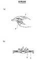
以下、本発明の実施形態を図面を参照しながら説明する。図2は、本発明の実施形態に係る情報入力装置又は情報入力法を示す説明図である(同図(a)は平面図、同図(b)は断面図、同図(c)は操作状態を示す説明図)。 Embodiments of the present invention will be described below with reference to the drawings. FIG. 2 is an explanatory view showing an information input device or information input method according to an embodiment of the present invention (FIG. 2A is a plan view, FIG. 2B is a sectional view, and FIG. 2C is an operation). Explanatory drawing which shows a state).
本発明の実施形態に係る情報入力装置又は情報入力方法は、人間の行う動作の中で指先の動作が最も分解能の高い動作であり、また、特に指先又は指の一部で物を挟持する際には、指先又は指の一部に神経が集中しやすく、人間の意志どおりに物を動かし易いという事実を利用したものであって、片手の二本の指先又は指の一部(例えば、親指の指先と人差し指の第2関節以上の先端部分)で物を挟んで摺り合わせる動作を情報入力装置の入力操作に活用したものである。 In the information input device or the information input method according to the embodiment of the present invention, the operation of the fingertip is the operation with the highest resolution among the operations performed by human beings, and particularly when an object is pinched by the fingertip or a part of the finger. Is based on the fact that nerves tend to concentrate on the fingertip or part of the finger, and that it is easy to move things according to the will of the human, and the two fingertips or part of the finger (for example, the thumb) The operation of sandwiching an object between the tip of the fingertip and the index finger and the second joint or more) is used for the input operation of the information input device.
図2(a)及び(b)は、本発明の実施形態に係る情報入力装置の基本構成を示すものである。この情報入力装置10は、片手の指先又は指の一部で挟持して相対的に摺動可能な二枚の板状入力部材11,12を備える。そして、板状入力部材11,12の相対位置又は相対移動に応じて入力情報を形成する情報形成部(図示省略)を備えている。 2A and 2B show the basic configuration of the information input device according to the embodiment of the present invention. The
また、二枚の板状入力部材11,12は、例えば図2(b)に示すように、互いに分離不能に保持されている。板状入力部材11,12の間にグリス等の高粘度の液体を注入すると、摺動が滑らかになるとともに、ある程度の抵抗感が得られて好ましい。図示の例では、一方の板状入力部材11に袋状空間を形成し、他方の板状入力部材12の一部を前記の袋状空間にはめ込んだ構造にしているが、特にこれに限定されるものではない。必要に応じて、二枚の板状入力部材11,12の動作方向を規制する規制手段を備えるものであってもよい。 Further, the two plate-
更に詳しくは、二枚の板状入力部材11,12は、対面する摺接面11a,12aとその背面側に指先又は指の一部に当接される当接面11b,12bを備え、板状入力部材11,12の一方の当接面12bが親指の腹部に当接可能である(図2(c)参照)。また、当接面11bには必要に応じて指の形状にフィットするように凹凸部分hを形成することもできる。図2(c)の場合、人差し指が凹凸部分hで固定されるので、板状入力部材11に設けたセンサーによる板状入力部材12の動きの方向、つまり人差し指に対する親指の動きの方向が特定しやすくなり好ましい。 More specifically, the two plate-
図2(c)によって、情報入力装置10の使用形態を説明すると、親指を上に他の指(例えば人差し指)を下にして、二枚の板状入力部材11,12を挟みもち、摺動動作をおこなう。そして、この二枚の板状入力部材11,12の相対位置又は相対移動に応じて図示省略の情報形成部が入力情報を形成する。 2 (c), the usage of the
このような実施形態に係る情報入力装置又は情報入力方法によると、先ず、片手での可搬性があるので操作の自由度が高く、操作者は様々な姿勢で入力操作を行うことが可能になる。そして、指先又は指の一部で二枚の板状入力部材11,12を挟持しこれらを摺動させる入力操作が行われるので、人間の最も分解能が高い動作を利用して、しかも操作者の意志が反映されやすい動作で、入力操作を行うことが可能になる。これによって、操作自由度が高く、且つ操作分解能の高い情報入力を行うことができる。 According to the information input device or the information input method according to such an embodiment, first, since there is portability with one hand, the degree of freedom of operation is high, and the operator can perform input operations in various postures. . An input operation is performed in which the two plate-
以下に、前述した情報形成部の具体例を説明する。
まず、情報形成部として、板状入力部材11,12の相対位置変位検出手段(センサー)を挙げることができる。本発明の実施形態に係る情報入力装置10は、GUIの入力装置として高いポインティング(位置情報の入力)性能を得るためには、できれば現在普及している表示装置の分解能程度(約千ドット)の精度をもって位置情報が入力できることが望ましい。これに対して、本発明の実施形態に係る情報入力装置10は、指と指の相対位置変位を利用するものでその変位の範囲は大きくない(操作性を考慮しても大きくないことが望ましい)ので、板状入力部材11,12の相対位置変位の分解能が10ミクロン以下になることが考えられる。Below, the specific example of the information formation part mentioned above is demonstrated.
First, as the information forming unit, a relative position displacement detecting means (sensor) of the plate-
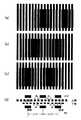
このような微細な二枚の板の相対位置変位を検出する方法の一つとして、図3にモアレ縞を用いた相対位置変位検出の実施例を示す。よく知られているように、モアレ縞は元来絹織物など細かな網目の重なりによって生じる波紋状の模様をいうが、この現象を利用すると微細な位置変位がそれよりもはるかに大きな波紋状のスケールの変化として現れるので、微小な位置変位の検出が必要な本発明に有効である。 As one of the methods for detecting the relative position displacement of such two fine plates, FIG. 3 shows an embodiment of relative position displacement detection using moire fringes. As is well known, moire fringes are originally rippled patterns such as silk fabrics that are overlapped by fine meshes, but if this phenomenon is used, the fine positional displacement is much larger than that. Since it appears as a change in scale, it is effective for the present invention that requires detection of a minute positional displacement.
本実施例の相対位置変位検出器の構成は、光を透過する部分と光を遮断する部分が交互に縦縞状になった二枚のフィルム様のシートが、位置変位の検出対象である上下の板状入力部材の摺動面12a,11aにそれぞれ配置され、それらを挟んで発光素子(LED)、受光素子(PD)がそれぞれ上下の板状入力部材12,11の中に配置されている(図8、図3(d)参照。図では光の透過部分を白、遮断する部分を黒で表している。)。各シートにおいて、縞の透過部分と遮断部分の幅は同一であり、上側シートの縞(上縞)の幅をdu,下側のシートの幅(下縞)の幅をdlとする。The configuration of the relative position displacement detector of the present embodiment is such that two film-like sheets in which light transmitting portions and light blocking portions are alternately formed in vertical stripes are positioned on the upper and lower sides, which are position displacement detection targets. The light-emitting elements (LEDs) and the light-receiving elements (PD) are disposed in the upper and lower plate-shaped
次に本検出器の動作を説明する。二枚の重なった縦縞のシート(その縞の幅は上下のシートでわずかに違う)を上から見たのが図3(a)〜(c)である(理解しやすくするため下のシートの縦幅を小さく描いている。但し、モアレの現象を視覚的に示す図のため、図3(d)との位置関係は一致していない。)。図3(a)の状態から上のシートが左方向に縞幅分だけ変位していくと(相対的には下のシートが右方向に移動するのと同じ)、重なりによるモアレ縞は(b),(c)のように変化し、例えばこのとき一番左側の受光素子(PD)に注目すると、光の透過状態(a)から半透過状態(b)を経て、遮断状態(c)になる。すなわち受光素子PDの出力電流は最大のON状態から徐々に減少し電流が流れないOFF状態に変化する。さらにシートが左に縞幅分だけ動くと、今度は出力電流がOFF状態からからON状態に変化する。 Next, the operation of this detector will be described. FIGS. 3A to 3C show two overlapping vertical striped sheets (the widths of the strips are slightly different between the upper and lower sheets) from above (for the sake of easy understanding, the bottom sheet) The vertical width is drawn small, but the positional relationship with FIG. When the upper sheet is displaced to the left by the stripe width from the state of FIG. 3A (relatively the same as the lower sheet moves to the right), the moire fringes due to the overlap are (b ), (C), for example, when attention is paid to the leftmost light receiving element (PD) at this time, the light transmission state (a) passes through the semi-transmission state (b) and then changes to the blocking state (c). Become. That is, the output current of the light receiving element PD gradually decreases from the maximum ON state and changes to the OFF state where no current flows. When the sheet further moves to the left by the stripe width, the output current changes from the OFF state to the ON state.
したがってこの電流の変化(ON→OFF、OFF→ON)の数nをカウントすると、変位距離が、シートの縞幅×電流の変化の数n、によって算出できる。縞幅が例えば10ミクロンであればこの10ミクロンの単位(精度)で位置変位量が検出できることになる。 Therefore, when the number n of the current changes (ON → OFF, OFF → ON) is counted, the displacement distance can be calculated by the sheet stripe width × the number n of current changes. If the fringe width is 10 microns, for example, the positional displacement amount can be detected in units of 10 microns (accuracy).
この位置変位量とともに、さらに左右の移動方向を検出するため、図3(d)に示すように三組の発光素子(LED)と受光素子(PD)を設ける。中央のPDの状態(ON状態/OFF状態)とその変化する前の左右のPDのON/OFF状態と比較し、同じ状態を持っていたPDがどちら側のPDであるかによって左右の移動方向を検出する。ちなみにモアレ縞の間隔Lは、上下の縞の幅をそれぞれdu,dlとすると、その縞幅の差に反比例しており、L=dudl/│du−dl│で表され、上述の三個の受光素子と発光素子は、この半分の間隔L/2を隔てて配置される。In order to further detect the left and right moving directions along with this positional displacement amount, three sets of light emitting elements (LEDs) and light receiving elements (PD) are provided as shown in FIG. Compared to the center PD state (ON state / OFF state) and the left / right PD ON / OFF state before the change, the left and right movement directions depend on which side the PD that has the same state is. Is detected. Table Incidentally distance L of the Moire fringes, the width of eachd u of the upper and lower fringes, in Whend l, and inversely proportional to the difference between the fringewidth, L = d u d l / │d u -d l │ Then, the three light receiving elements and the light emitting elements described above are arranged with a half distance L / 2 therebetween.
以上は一つの方向(X軸とする)に関する検出について述べたが、同様にこれと直角方向(Y軸とする)の移動も上述した三組の発光、受光素子をY軸方向に配置することによって可能である。 The above description is about detection in one direction (X axis). Similarly, for the movement in the direction perpendicular to this (Y axis), the above three sets of light emitting and receiving elements are arranged in the Y axis direction. Is possible.
以上モアレ縞を利用した相対位置変位を検出する方法を説明したが、相対位置変位を検出できる方法であればこれに限られない。例えば抵抗薄膜センサーやマグネスケールなども分解能があり、しかも薄いシート状で実現できるのでこの相対位置変位検出手段として使ってもよい。 Although the method for detecting the relative position displacement using the moire fringes has been described above, the method is not limited to this as long as the method can detect the relative position displacement. For example, a resistance thin film sensor or a magnescale has a resolution and can be realized in the form of a thin sheet, so that it may be used as this relative position displacement detecting means.
次に、情報形成部として圧力検出手段(センサー)を備えた実装例について図4及び図8を参照しながら説明する。図4(a)に示す圧力検出手段(センサー)17はここでは上側の板状入力部材12に一つ配置されている実施例を示すが、例えば下側の板状入力部材11に配置することも可能であり、また、複数個配置することも可能である。さらにクリック感を得るためにばね構造を設けてもよい。 Next, a mounting example provided with a pressure detection means (sensor) as an information forming unit will be described with reference to FIGS. In this embodiment, one pressure detection means (sensor) 17 shown in FIG. 4A is arranged on the upper plate-
この圧力センサー17は、一つにはマウスのいわゆるクリックに相当する機能(そのカーソル位置での入力指示機能)を果たすことができる。この動作は、短時間に摺動動作時の指圧よりも高い圧力をかけることで行うことができる。 For example, the
また、圧力センサー17は、図4(b)に示すように例えば圧電センサーを使用した場合には、指で押された圧力に応じたアナログ電圧信号を、無操作状態、摺動操作状態、クリック状態の3つの圧力状態に弁別して検出する機能を備えている。 As shown in FIG. 4B, for example, when a piezoelectric sensor is used as the
これは、クリック機能に加えて、操作(摺動)時のみ上記相対位置検出手段からの信号を外部に送る機能を持たせるためであり、そのために、指を板状入力部材12に載せて摺動するときの圧力と無操作時の圧力とを区別し、無操作時の圧力では上記相対位置検出手段からの信号を止めるという機能を付加したものである。 This is to provide a function of sending a signal from the relative position detecting means to the outside only during an operation (sliding) in addition to a click function. For this purpose, a finger is placed on the plate-
そのための回路例を図4(c)に示す。抵抗R1,R2と二つのコンパレーターからなり、抵抗R1,R2の調整で無操作状態と摺動操作状態の圧力識別、摺動操作状態とクリック状態の圧力識別の最適化を図ることができる。そして最終的に2つの出力のON,OFFの組み合わせで3状態が識別され、上述したクリック検出、相対位置変位検出信号の送出の制御等に使うことができる。もちろん、このような回路を用いず、例えば圧力センサーの出力電圧をAD変換してから、デジタル的に三圧力状態を識別することもできる。 A circuit example for this purpose is shown in FIG. It consists of resistors R1 and R2 and two comparators. By adjusting the resistors R1 and R2, it is possible to optimize pressure identification between the non-operation state and the sliding operation state, and pressure identification between the sliding operation state and the click state. Finally, the three states are identified by the combination of ON and OFF of the two outputs, and can be used for the above-described click detection, control of sending the relative position displacement detection signal, and the like. Of course, without using such a circuit, for example, it is also possible to digitally identify the three pressure states after AD converting the output voltage of the pressure sensor.
上述した相対位置変位検出手段と圧力検出手段によって、マウスの機能で云えば位置情報入力機能とクリック機能を備えることができるが、次に説明する傾きセンサーの採用によって、マウスの左右クリック識別機能を持たせることができる。 The above-mentioned relative position displacement detection means and pressure detection means can be provided with a position information input function and a click function in terms of the mouse function. You can have it.
図5及び図8は、板の特定方向への傾きを検知する傾きセンサー18を備えた実施例を示したものである。傾きセンサー18としてこの例では、近接スイッチを使ったものを示しているが、光スイッチ,接触スイッチ等を使うこともできる。このセンサーを備えることにより、例えば手で保持する左右の傾きを検出し、その傾き信号と、前述の圧力センサーで検出したそのときのクリック信号を組み合わせることにより、二つボタンマウスのいわゆる左クリックあるいは右クリックに対応した入力が可能になる。 5 and 8 show an embodiment provided with an
もちろん、2つの圧力検出センサーを例えば板状入力部材12の左右に2個分けて配置し、指圧の左右のセンサーでの違いを検出することによっても左右クリックの検出は可能である。また、複数の圧力センサー又は分割された複数の検出部を有する大面積の圧力センサーを採用すると共に、圧力状態を連続的に検出できるようにして、二次元的なカーソルの移動を検出部の選択と押圧力とによって制御するような実施形態も可能である。 Of course, it is possible to detect left and right clicks by arranging two pressure detection sensors separately on the left and right sides of the plate-
次に1次元的に動く可動部材を備えた実施例の一つとして、板状入力部材11の周りに回動可能な回動リング20を備えた例を図6に示す。回動リング20はこの板状入力部材11の周りを回動できる構造になっており、この回動リング20と板状入力部材11との間にその相対位置変位を検出する1次元変位センサー22を配置する。これにより回動リング20の回転変位が検知され回転変位に応じた信号が出力される。すなわち、この回動リング20の位置を調整することで、それに応じた信号が外部に送出されるので、例えば対象機器の音量調整やマウスのセンターローラーの役割を持たせることができる。 Next, FIG. 6 shows an example in which a
この1次元変位センサー22として、上述した板状入力部材の相対変位検出に用いたのと同様なモアレ縞を利用したセンサーの例を図8に示す。この例は反射型光学スリットセンサーを用いるもので、板状入力部材11上の光源LED21からの光を透過縞パターンと反射光学スリット23を通して回動リング20に付けられた縞パターンに当て、そこからの反射光を同じく板状入力部材11上にあるセンサーPD22で受光して相対位置変位を検出する。その他、透過型光学スリットセンサー、磁気スケール、抵抗シート型変位センサー等を適時利用できる。 FIG. 8 shows an example of a sensor that uses the same moire fringes as the one-
次にトグルスイッチ機能について説明する。これは上に述べてきた各種検出センサーに急激な変化を与えることによって、通常の入力状態と異なる状態であることを検知してモード切り替えなどを行う機能である。この機能を利用することによって、新たなスイッチ等を設けることなく、例えば上述した1次元変位センサーの動作モードを切り替えること等が可能になる。 Next, the toggle switch function will be described. This is a function for performing mode switching by detecting a state different from the normal input state by giving abrupt changes to the various detection sensors described above. By using this function, for example, the operation mode of the one-dimensional displacement sensor described above can be switched without providing a new switch or the like.
例えばモアレ縞を利用した相対位置変位検出手段にこのトグルスイッチ機能を持たせるには、急激に板を動かす、すなわち短時間に特別多くのパルスをカウントすることを検出することによって行うことができる。 For example, the relative position displacement detection means using the moire fringes can have this toggle switch function by detecting that the plate is moved suddenly, that is, a particularly large number of pulses are counted in a short time.
また、圧力センサー17によって行うときは、通常のクリック動作より長いクリック動作の検出、あるいは摺動時動作と無操作動作の繰り返し(摺動動作圧力と無圧力の繰り返し)を短時間に行なわれたことの検出でおこなう。 When the
また、傾きセンサー18によって行うときは、短時間の間に例えば右、左、右と傾けること、又は手を振ることによる信号のON,OFF,ONを検出することによって行うことが可能である。 In addition, when the
図7は,以上述べてきた各種センサーからの検出信号が信号形態変換器(エンコーダIC)24で統合され、また情報入力対象機器の信号形態(例えばUSB信号など)に適合した信号出力になるよう変換されて、外部に送信されるようすを示したブロック図である。 In FIG. 7, the detection signals from the various sensors described above are integrated by a signal form converter (encoder IC) 24, and the signal output conforms to the signal form (for example, USB signal) of the information input target device. FIG. 3 is a block diagram illustrating a state where the data is converted and transmitted to the outside.
図8はこれまで述べた全ての機能を盛り込んだ統合的な実施形態を示すものである。大半の機能はすでに説明したとおりである。指での当接を容易にするための保持用凸凹構造30,板状入力部材12の回転運動を制限するための回転制限用窪みおよび突起31、また摺動する板状入力部材間の信号、電力伝送用の結線の自由度を保つための結線用逃げ溝32などの機構を備えている。各種センサーの配置を説明すると、板状入力部材11側には、その底部に保持用凸凹構造30が形成され、前述した相対位置検出手段を構成するX方向パターン13b,Y方向パターン14b,受光素子(PD)16、前述した変位センサー22を構成する光源LED21、信号形態変換器24が装備されており、この信号形態変換器24に出力・電源線25が接続されている。また、板状入力部材11の外周には、前述の変位センサー22の回動リング20が装備されている。また、板状入力部材12側には、前述した相対位置検出手段を構成するX方向パターン13a,Y方向パターン14a,発光素子(LED)15、圧力センサー17、傾きセンサー18(球19)が装備されている。 FIG. 8 shows an integrated embodiment incorporating all the functions described so far. Most of the functions have already been explained. A holding convex /
図9及び図10は、本発明の他の実施形態を示す説明図である。これらの実施形態では、板状入力部材11,12の相対変位を、これらを挟持する指で直接感じることができるようにしたものである。 9 and 10 are explanatory diagrams showing other embodiments of the present invention. In these embodiments, the relative displacement of the plate-
図9に示す実施形態では、二枚の板状入力部材11,12の一方に穴部40が設けられており(図示の例では、上側の板状入力部材12側に穴部40を設けているが、これに限らず下側の板状入力部材11側に穴部40を設けてもよい)、この穴部40は、板状入力部材11,12の相対変位を他方の板状入力部材11又は12から受ける感覚の変化として指先又は指の一部が感じられる開口40Aを有すると共に、指先又は指の一部が接する側面40Bを有する。また、この側面40Bは、指の大きさの個人差に対応できるように、テーパ状に形成されている。 In the embodiment shown in FIG. 9, a
これによると、例えば、板状入力部材12側に当接する親指Fsが、開口40Aを介して直接板状入力部材11の摺接面に触れて、板状入力部材11,12間で生じた相対変位を指の感覚変化で直接感知することができ。また、指が穴部40の側面40Bに接しているので、指の移動を板状入力部材11,12の相対移動に直結させることができる。これによって、感度の高い指の感覚変化に応じて板状入力部材11,12間の相対移動を操作することができるので、操作感が高まり、微細入力をストレス無く行うことができる。 According to this, for example, the thumb Fs that is in contact with the plate-
また、図10に示す実施形態では、二枚の板状入力部材11,12の両方に、それぞれ穴部41,42が設けられ、各穴部41,42は、二枚の板状入力部材11,12を挟持する指先又は指の一部が互いに接して、板状入力部材11,12の相対変位を両指の感覚の変化として感じられる開口41A,42Aを有すると共に、指先又は指の一部が接する側面41B,42Bを有する。 In the embodiment shown in FIG. 10, both of the two plate-
これによっても、例えば、開口41A,42Aを介して互いに接する親指Fsと他の指Foによって、板状入力部材11,12間で生じた相対変位を両方の指の感覚変化で感知でき、また、指が穴部41,42の側面41B,42Bに接しているので、指の移動を板状入力部材11,12の相対移動に直結させることができる。これによっても、感度の高い指のずれ感覚に応じて板状入力部材11,12間の相対移動を操作することができるので、操作感が高まり、微細入力をストレス無く行うことができる。特に、指同士の感覚変化を採用するので、より高感度で、ストレスの無い微細入力が可能になる。 Also by this, for example, the relative displacement generated between the plate-
なお、ここでいう感覚の変化とは、指と板状入力部材11又は12(図9の例)或いは指同士(図10の例)がずれる又は滑る時の振動或いは圧力変化によって生じる感覚の変化は勿論のこと、指と板状入力部材11又は12或いは指同士は未だずれたり滑ったりしない状態において、微妙な指の変形によって生じる感覚の変化をも含むものである。そして、前述した穴部40,41,42の開口40A,41A,42Aは、この感覚変化を指先又は指の一部で感じ取ることができる所定の大きさが必要になる。 Note that the change in sensation here refers to a change in sensation caused by vibration or pressure change when the finger and the plate-
また、図9及び図10の実施形態においても、図8の実施形態と同様に各種センサー等を装備することができる(図9に示した実施形態では、穴部40を設けていない側の板状入力部材11(12)の背面に保持用凸凹機構50が形成されている)。例えば、板状入力部材11側に、半導体センサー等からなる傾きセンサー51、LEDと反射型XY方向パターン,受光素子からなる変位センサーの一部52A、信号形態変換器53、この信号形態変換器53に接続された出力信号線・電源線54が装備され、板状入力部材12側に、変位センサーの反射部52B、感圧抵抗シートなどから成る圧力センサー55が装備されている。また、板状入力部材11,12の回転制限用窪みおよび突起56が配線用逃げ部を兼用して設けられている。 9 and 10 can be equipped with various sensors and the like as in the embodiment of FIG. 8 (in the embodiment shown in FIG. 9, the plate on the side where the
以上、本願の実施形態に係る情報入力装置では、情報形成部の形態は前述の例に限らず各種の形態を採用することが可能である。本発明の実施形態の特徴は、このような情報形成部の形態に拘わらず、片手の指先又は指の一部で挟持して相対的に摺動可能な二枚の板状入力部材11,12を備え、少なくともこの板状入力部材11,12の相対位置又は相対移動に応じて入力情報を形成することにある。これによって、本発明の実施形態では、可搬性を持たせることで操作自由度を向上させると共に、人間の指がもつ鋭敏な感覚、優れた分解能を利用し、微細な位置入力が可能であり、また、多種類の情報入力を単純な入力部の操作で入力することが可能になる。 As described above, in the information input device according to the embodiment of the present application, the form of the information forming unit is not limited to the above example, and various forms can be adopted. The feature of the embodiment of the present invention is that the two plate-
10 情報入力装置
11、12 板状入力部材
11a,12a 板状入力部材の摺接面
11b,12b 板状入力部材の背面側(当接面)
13,13a,13b X方向相対位置変位検出用パターン(X方向パターン)
14,14a,14b Y方向相対位置変位検出用パターン(Y方向パターン)
15 光源LED(レーザダイオード)
16 変位検出用センサー(フォトダイオードPD)
17,55 圧力センサー
18,51 傾きセンサー
19 球
20 回動リング
21 回転変位検出用光源LED
22 回転変位検出用センサーPD
23 反射光学スリット
24,53 信号形態変換器
25,54 出力信号・電源線
30,50 保持用凸凹構造
31,56 回転制限用窪みおよび突起
32 結線用逃げ溝
40,41,42 穴部
40A,41A,42A 開口
40B,41B,42B 側面
52A 変位センサーの一部
52B 変位センサーの反射部
DESCRIPTION OF
13, 13a, 13b X direction relative position displacement detection pattern (X direction pattern)
14, 14a, 14b Y-direction relative position displacement detection pattern (Y-direction pattern)
15 Light source LED (laser diode)
16 Sensor for displacement detection (photodiode PD)
17, 55
22 Sensor PD for rotational displacement detection
23 Reflective
Claims (13)
Translated fromJapanese前記二枚の板状入力部材の一方には穴部が設けられ、該穴部は、前記二枚の板状入力部材の相対変位を他方の前記板状入力部材から受ける感覚の変化として前記指先又は指の一部が感じられる開口を有すると共に、前記指先又は指の一部が接する側面を有する
ことを特徴とする情報入力装置。Provided with two plate-like input members that can be slid by being sandwiched by a fingertip or a part of a finger of one hand, and at least input information is formed according to the relative position or relative movement of the plate-like input member With an information formation unit,
One of the two plate-like input members is provided with a hole, and the hole has a fingertip as a change in sensation of receiving a relative displacement of the two plate-like input members from the other plate-like input member. Alternatively , the information input device includesan opening through which a part of a finger can be felt and a side surface on which the fingertip or part of the finger contacts .
前記二枚の板状入力部材の両方にはそれぞれ穴部が設けられ、各穴部は、前記二枚の板状入力部材の相対変位を互いに接することで受ける感覚の変化として前記指先又は指の一部が感じられる開口を有すると共に、前記指先又は指の一部が接する側面を有するBoth of the two plate-like input members are each provided with a hole, and each hole has a fingertip or finger change as a change in sensation received by contacting the relative displacement of the two plate-like input members with each other. It has an opening where a part can be felt and a side where the fingertip or part of the finger touches
ことを特徴とする情報入力装置。An information input device characterized by that.
前記二枚の板状入力部材の一方には穴部が設けられ、該穴部は、前記二枚の板状入力部材の相対変位を他方の前記板状入力部材から受ける感覚の変化として前記指先又は指の一部が感じられる開口を有すると共に、前記指先又は指の一部が接する側面を有する
ことを特徴とする情報入力方法。Two plate-like input members that can be slid relative to each other are sandwiched between the fingertips of one hand or a part of the finger, and the two plate-like input members are slid to operate relative to each other. Form input information according to position or relative movement,
One of the two plate-like input members is provided with a hole, and the hole has a fingertip as a change in sensation of receiving a relative displacement of the two plate-like input members from the other plate-like input member. Alternatively , the information input method includesan opening through which a part of a finger can be felt and a side surface on which the fingertip or part of the finger contacts .
前記二枚の板状入力部材の両方にはそれぞれ穴部が設けられ、各穴部は、前記二枚の板状入力部材の相対変位を互いに接することで受ける感覚の変化として前記指先又は指の一部が感じられる開口を有すると共に、前記指先又は指の一部が接する側面を有するBoth of the two plate-like input members are each provided with a hole, and each hole has a fingertip or finger change as a change in sensation received by contacting the relative displacement of the two plate-like input members with each other. It has an opening where a part can be felt and a side where the fingertip or part of the finger touches
ことを特徴とする情報入力方法。An information input method characterized by that.
Priority Applications (4)
| Application Number | Priority Date | Filing Date | Title |
|---|---|---|---|
| JP2005066564AJP4588496B2 (en) | 2004-03-25 | 2005-03-10 | Information input device and information input method |
| EP05006608AEP1585017B1 (en) | 2004-03-25 | 2005-03-24 | Information input device |
| DE602005017694TDE602005017694D1 (en) | 2004-03-25 | 2005-03-24 | Data entry device |
| US11/089,033US7652659B2 (en) | 2004-03-25 | 2005-03-25 | Information input device and method |
Applications Claiming Priority (2)
| Application Number | Priority Date | Filing Date | Title |
|---|---|---|---|
| JP2004088416 | 2004-03-25 | ||
| JP2005066564AJP4588496B2 (en) | 2004-03-25 | 2005-03-10 | Information input device and information input method |
Publications (2)
| Publication Number | Publication Date |
|---|---|
| JP2005327252A JP2005327252A (en) | 2005-11-24 |
| JP4588496B2true JP4588496B2 (en) | 2010-12-01 |
Family
ID=34914547
Family Applications (1)
| Application Number | Title | Priority Date | Filing Date |
|---|---|---|---|
| JP2005066564AExpired - Fee RelatedJP4588496B2 (en) | 2004-03-25 | 2005-03-10 | Information input device and information input method |
Country Status (4)
| Country | Link |
|---|---|
| US (1) | US7652659B2 (en) |
| EP (1) | EP1585017B1 (en) |
| JP (1) | JP4588496B2 (en) |
| DE (1) | DE602005017694D1 (en) |
Families Citing this family (7)
| Publication number | Priority date | Publication date | Assignee | Title |
|---|---|---|---|---|
| JP4366246B2 (en)* | 2004-05-26 | 2009-11-18 | パイオニア株式会社 | Information input device |
| US7522154B2 (en)* | 2004-07-29 | 2009-04-21 | Avago Technologies Ecbu Ip (Singapore) Pte. Ltd. | Slide pad notebook pointing device with hidden spring system |
| TWI311275B (en)* | 2006-05-04 | 2009-06-21 | Sunplus Technology Co Ltd | Apparatus and method for cursor control |
| WO2016049842A1 (en)* | 2014-09-30 | 2016-04-07 | 汪伟 | Hybrid interaction method for portable or wearable intelligent device |
| WO2017208645A1 (en)* | 2016-05-31 | 2017-12-07 | 国立大学法人九州大学 | Flow volume measuring device, flow volume measuring method, pressure measuring device, and pressure measuring method |
| CN107203281A (en)* | 2017-06-26 | 2017-09-26 | 厦门理工学院 | A kind of finger cot type input method and device |
| US12106739B2 (en)* | 2020-05-21 | 2024-10-01 | Parker J Wosner | Manual music generator |
Family Cites Families (22)
| Publication number | Priority date | Publication date | Assignee | Title |
|---|---|---|---|---|
| EP0477098B1 (en)* | 1990-09-18 | 1996-06-26 | Fujitsu Limited | Cursor displacement control device for a computer display |
| DE69233132T2 (en)* | 1991-05-15 | 2004-07-29 | Fujitsu Ltd., Kawasaki | Information arrangement and control device of the same |
| JPH07117875A (en) | 1993-10-28 | 1995-05-09 | Canon Inc | Automatic paper feeder and recorder |
| GB9403147D0 (en)* | 1994-02-18 | 1994-04-06 | Gentech Int Ltd | Sensor apparatus |
| US5666138A (en)* | 1994-11-22 | 1997-09-09 | Culver; Craig F. | Interface control |
| US5943044A (en)* | 1996-08-05 | 1999-08-24 | Interlink Electronics | Force sensing semiconductive touchpad |
| JPH10207616A (en)* | 1997-01-20 | 1998-08-07 | Sharp Corp | Input device |
| JPH10301706A (en) | 1997-04-24 | 1998-11-13 | Nec Niigata Ltd | Mounting type pointing device |
| US6256011B1 (en)* | 1997-12-03 | 2001-07-03 | Immersion Corporation | Multi-function control device with force feedback |
| US6300938B1 (en)* | 1998-04-13 | 2001-10-09 | Immersion Corporation | Multiple-cylinder control device for computers and other electronic apparatus |
| EP1078353A4 (en)* | 1998-05-20 | 2004-04-28 | Kwan-Ho Chan | Finger controlled computer mouse |
| JP2000137564A (en)* | 1998-11-02 | 2000-05-16 | Pioneer Electronic Corp | Picture operating device and its method |
| JP2000305709A (en)* | 1999-04-26 | 2000-11-02 | Alps Electric Co Ltd | Electronics |
| JP2001125722A (en)* | 1999-11-01 | 2001-05-11 | Sharp Corp | Remote control device |
| AU1761401A (en)* | 1999-11-12 | 2001-06-06 | Acco Brands, Inc. | A pointing device with an annular rotating ring |
| GB9928682D0 (en)* | 1999-12-06 | 2000-02-02 | Electrotextiles Comp Ltd | Input apparatus and a method of generating control signals |
| JP3971079B2 (en)* | 2000-03-14 | 2007-09-05 | アルプス電気株式会社 | Input device and detection device |
| US6580420B1 (en)* | 2000-03-15 | 2003-06-17 | Yanqing Wang | Convertible computer input device |
| NO312384B1 (en)* | 2000-04-26 | 2002-04-29 | Sverre E Larsen | Finger-controlled computer mouse |
| JP3993986B2 (en)* | 2001-03-06 | 2007-10-17 | インターナショナル・ビジネス・マシーンズ・コーポレーション | Input device and information processing device |
| TWI234115B (en)* | 2002-04-03 | 2005-06-11 | Htc Corp | Method and device of setting threshold pressure for touch panel |
| KR20040027294A (en)* | 2003-07-02 | 2004-04-01 | 포스텍전자주식회사 | Sliding hinge apparatus |
- 2005
- 2005-03-10JPJP2005066564Apatent/JP4588496B2/ennot_activeExpired - Fee Related
- 2005-03-24EPEP05006608Apatent/EP1585017B1/ennot_activeExpired - Lifetime
- 2005-03-24DEDE602005017694Tpatent/DE602005017694D1/ennot_activeExpired - Lifetime
- 2005-03-25USUS11/089,033patent/US7652659B2/ennot_activeExpired - Fee Related
Also Published As
| Publication number | Publication date |
|---|---|
| EP1585017B1 (en) | 2009-11-18 |
| US20050225529A1 (en) | 2005-10-13 |
| EP1585017A3 (en) | 2006-08-23 |
| EP1585017A2 (en) | 2005-10-12 |
| US7652659B2 (en) | 2010-01-26 |
| DE602005017694D1 (en) | 2009-12-31 |
| JP2005327252A (en) | 2005-11-24 |
Similar Documents
| Publication | Publication Date | Title |
|---|---|---|
| US7081883B2 (en) | Low-profile multi-channel input device | |
| US7042441B2 (en) | Input device including a scroll wheel assembly for manipulating an image in multiple directions | |
| EP0653725B1 (en) | Co-ordinate input device | |
| CN114578964A (en) | Finger-worn device with sensor and haptic | |
| US20100103103A1 (en) | Method And Device for Input Of Information Using Visible Touch Sensors | |
| KR20110132529A (en) | Integrated fingerprint sensor and navigation device | |
| KR20060017512A (en) | Multifunction floating button | |
| US11216082B2 (en) | Active stylus | |
| JPH11194891A (en) | Mouse pointing device | |
| JP2009258946A (en) | Capacitive touch sensor | |
| US20050219355A1 (en) | Information input device | |
| CN111587414A (en) | Multifunctional touch control pen | |
| JP4588496B2 (en) | Information input device and information input method | |
| KR100802456B1 (en) | Fixed mouse | |
| KR102733461B1 (en) | Electronic device having multi functional human interface and method for controlling the same | |
| KR101106278B1 (en) | Complex input device with touch function | |
| CN113190130B (en) | Touch-control type active pen | |
| EP1594043A2 (en) | Information input device and information input method | |
| JP2007249459A (en) | Data input device | |
| KR101632841B1 (en) | Mouse | |
| JP4366246B2 (en) | Information input device | |
| KR20100066728A (en) | Ring type input device and method thereof | |
| JP3108374U (en) | Cursor pointing device controlled using vibration | |
| JP2000315136A (en) | Method for detecting movement quantity of mouse and optical mouse | |
| KR200264835Y1 (en) | Track ball mouse |
Legal Events
| Date | Code | Title | Description |
|---|---|---|---|
| A621 | Written request for application examination | Free format text:JAPANESE INTERMEDIATE CODE: A621 Effective date:20080207 | |
| A977 | Report on retrieval | Free format text:JAPANESE INTERMEDIATE CODE: A971007 Effective date:20091201 | |
| A131 | Notification of reasons for refusal | Free format text:JAPANESE INTERMEDIATE CODE: A131 Effective date:20091204 | |
| A521 | Request for written amendment filed | Free format text:JAPANESE INTERMEDIATE CODE: A523 Effective date:20100127 | |
| TRDD | Decision of grant or rejection written | ||
| A01 | Written decision to grant a patent or to grant a registration (utility model) | Free format text:JAPANESE INTERMEDIATE CODE: A01 Effective date:20100907 | |
| A01 | Written decision to grant a patent or to grant a registration (utility model) | Free format text:JAPANESE INTERMEDIATE CODE: A01 | |
| A61 | First payment of annual fees (during grant procedure) | Free format text:JAPANESE INTERMEDIATE CODE: A61 Effective date:20100908 | |
| R150 | Certificate of patent or registration of utility model | Free format text:JAPANESE INTERMEDIATE CODE: R150 | |
| FPAY | Renewal fee payment (event date is renewal date of database) | Free format text:PAYMENT UNTIL: 20130917 Year of fee payment:3 | |
| LAPS | Cancellation because of no payment of annual fees |