JP4588294B2 - Fixation device for fixing bones, especially vertebral bodies relative to each other - Google Patents
Fixation device for fixing bones, especially vertebral bodies relative to each otherDownload PDFInfo
- Publication number
- JP4588294B2 JP4588294B2JP2002547394AJP2002547394AJP4588294B2JP 4588294 B2JP4588294 B2JP 4588294B2JP 2002547394 AJP2002547394 AJP 2002547394AJP 2002547394 AJP2002547394 AJP 2002547394AJP 4588294 B2JP4588294 B2JP 4588294B2
- Authority
- JP
- Japan
- Prior art keywords
- fixing device
- locking element
- blade
- rear end
- locking
- Prior art date
- Legal status (The legal status is an assumption and is not a legal conclusion. Google has not performed a legal analysis and makes no representation as to the accuracy of the status listed.)
- Expired - Fee Related
Links
- 210000000988bone and boneAnatomy0.000titleclaimsdescription55
- 230000008878couplingEffects0.000claimsdescription8
- 238000010168coupling processMethods0.000claimsdescription8
- 238000005859coupling reactionMethods0.000claimsdescription8
- 238000000034methodMethods0.000claims1
- 230000002093peripheral effectEffects0.000claims1
- 238000009964sergingMethods0.000claims1
- 239000007943implantSubstances0.000description13
- 230000001054cortical effectEffects0.000description8
- 238000006073displacement reactionMethods0.000description7
- 230000008901benefitEffects0.000description5
- 238000005520cutting processMethods0.000description4
- 230000007480spreadingEffects0.000description4
- 238000003892spreadingMethods0.000description4
- 206010017076FractureDiseases0.000description3
- 238000005516engineering processMethods0.000description3
- 230000002792vascularEffects0.000description3
- 208000010392Bone FracturesDiseases0.000description2
- 208000001132OsteoporosisDiseases0.000description2
- 238000005452bendingMethods0.000description2
- 230000001419dependent effectEffects0.000description2
- 230000004927fusionEffects0.000description2
- 210000005036nerveAnatomy0.000description2
- 238000005422blastingMethods0.000description1
- 239000011248coating agentSubstances0.000description1
- 238000000576coating methodMethods0.000description1
- 238000010276constructionMethods0.000description1
- 230000005786degenerative changesEffects0.000description1
- 238000010586diagramMethods0.000description1
- 238000009826distributionMethods0.000description1
- 230000000694effectsEffects0.000description1
- 238000005530etchingMethods0.000description1
- 239000012634fragmentSubstances0.000description1
- 230000035876healingEffects0.000description1
- 238000002513implantationMethods0.000description1
- 238000007689inspectionMethods0.000description1
- 238000005304joiningMethods0.000description1
- 230000013011matingEffects0.000description1
- 230000001009osteoporotic effectEffects0.000description1
- 230000000149penetrating effectEffects0.000description1
- 230000009467reductionEffects0.000description1
- 230000008263repair mechanismEffects0.000description1
- 238000007493shaping processMethods0.000description1
- 206010041569spinal fractureDiseases0.000description1
- 230000006641stabilisationEffects0.000description1
- 238000011105stabilizationMethods0.000description1
- 239000000758substrateSubstances0.000description1
- 238000001356surgical procedureMethods0.000description1
Images


Classifications
- A—HUMAN NECESSITIES
- A61—MEDICAL OR VETERINARY SCIENCE; HYGIENE
- A61B—DIAGNOSIS; SURGERY; IDENTIFICATION
- A61B17/00—Surgical instruments, devices or methods
- A61B17/56—Surgical instruments or methods for treatment of bones or joints; Devices specially adapted therefor
- A61B17/58—Surgical instruments or methods for treatment of bones or joints; Devices specially adapted therefor for osteosynthesis, e.g. bone plates, screws or setting implements
- A61B17/68—Internal fixation devices, including fasteners and spinal fixators, even if a part thereof projects from the skin
- A61B17/70—Spinal positioners or stabilisers, e.g. stabilisers comprising fluid filler in an implant
- A—HUMAN NECESSITIES
- A61—MEDICAL OR VETERINARY SCIENCE; HYGIENE
- A61B—DIAGNOSIS; SURGERY; IDENTIFICATION
- A61B17/00—Surgical instruments, devices or methods
- A61B17/56—Surgical instruments or methods for treatment of bones or joints; Devices specially adapted therefor
- A61B17/58—Surgical instruments or methods for treatment of bones or joints; Devices specially adapted therefor for osteosynthesis, e.g. bone plates, screws or setting implements
- A61B17/68—Internal fixation devices, including fasteners and spinal fixators, even if a part thereof projects from the skin
- A61B17/84—Fasteners therefor or fasteners being internal fixation devices
- A61B17/86—Pins or screws or threaded wires; nuts therefor
- A61B17/8625—Shanks, i.e. parts contacting bone tissue
- A—HUMAN NECESSITIES
- A61—MEDICAL OR VETERINARY SCIENCE; HYGIENE
- A61B—DIAGNOSIS; SURGERY; IDENTIFICATION
- A61B17/00—Surgical instruments, devices or methods
- A61B17/56—Surgical instruments or methods for treatment of bones or joints; Devices specially adapted therefor
- A61B17/58—Surgical instruments or methods for treatment of bones or joints; Devices specially adapted therefor for osteosynthesis, e.g. bone plates, screws or setting implements
- A61B17/68—Internal fixation devices, including fasteners and spinal fixators, even if a part thereof projects from the skin
- A61B17/70—Spinal positioners or stabilisers, e.g. stabilisers comprising fluid filler in an implant
- A61B17/7001—Screws or hooks combined with longitudinal elements which do not contact vertebrae
- A61B17/7002—Longitudinal elements, e.g. rods
- A61B17/7019—Longitudinal elements having flexible parts, or parts connected together, such that after implantation the elements can move relative to each other
- A61B17/7025—Longitudinal elements having flexible parts, or parts connected together, such that after implantation the elements can move relative to each other with a sliding joint
- A—HUMAN NECESSITIES
- A61—MEDICAL OR VETERINARY SCIENCE; HYGIENE
- A61B—DIAGNOSIS; SURGERY; IDENTIFICATION
- A61B17/00—Surgical instruments, devices or methods
- A61B2017/00831—Material properties
- A61B2017/00858—Material properties high friction or non-slip
Landscapes
- Health & Medical Sciences (AREA)
- Orthopedic Medicine & Surgery (AREA)
- Life Sciences & Earth Sciences (AREA)
- Surgery (AREA)
- Neurology (AREA)
- Heart & Thoracic Surgery (AREA)
- Engineering & Computer Science (AREA)
- Biomedical Technology (AREA)
- Nuclear Medicine, Radiotherapy & Molecular Imaging (AREA)
- Medical Informatics (AREA)
- Molecular Biology (AREA)
- Animal Behavior & Ethology (AREA)
- General Health & Medical Sciences (AREA)
- Public Health (AREA)
- Veterinary Medicine (AREA)
- Surgical Instruments (AREA)
- Prostheses (AREA)
Description
Translated fromJapanese【0001】
(技術分野)
本発明は、骨、特に椎体を互いに相対的に固定するための請求項1の前文に係る装置に関する。
【0002】
(背景技術)
椎骨骨折、変質性変化等によって引き起こされることのある脊柱運動分節の不安定性はしばしば当該分節の癒合を必要とする。癒合すべき運動分節の骨癒合に必要な定着を達成するために、当該分節は固定システムでさまざまに安定させられる。これらの固定システムは後方から挿入して係止し、茎部内で骨ねじを用いて係止を行うか、あるいは、前方もしくは前外側から挿入して係止し、椎体内で骨ねじを用いて係止を行うかのいずれかである。
【0003】
固定システムの係止の質は骨構造の質に強く左右される。これは特に前外側で係止される固定システムの場合に妥当する。骨粗鬆病度が大きければ大きいほど、骨ねじがすでに小さな荷重において骨を切断する危険が一層大きくなる。太いねじを使用すると切断の危険が小さくなる。しかし他方で、椎体内の骨構造を過度に強く破壊しないために過度に太いねじは使用したくない。
【0004】
係止要素の切断の危険を減らすための解決策がDE29600879 AESCULAPとWO00/10473 AEBIに示してある。そこで問題となっているのは基本的に、椎体にねじ込まれる中空ねじである。この中空ねじは、骨を多く押しのけることなくそれが大きな外径を有する利点を有する。ねじ込むとき中空ねじの中心に錐状骨が残る。この解決策の欠点として、
a)中空ねじをねじ込むとき、中心に残る錐状骨の血管分布が大部分破壊され、これは特に骨粗鬆症の骨の場合問題を生じることがあり、
b)修理機構がまだ機能する骨の場合中空ねじは、点検時に除去困難になるほどに、もしくは除去時に大きな骨障害を生じるほどに、強固に定着することがある(例えば、頚椎に挿入された中空ねじは一部ではもはや除去できなかった)。
【0005】
管状骨の骨折の手術処置に関連して髄内安定化技術が開発されたが、前および前外側脊柱固定システムを係止する問題を解決するためにこの技術は転じて脊柱でも成功裏に利用できる。
【0006】
髄内釘は、骨折した管形骨の近位部を遠位部と髄内で結合することによって、骨折した管形骨の副子固定に利用される。しかし髄内釘はその幾何学のゆえに小さな回転荷重および軸方向荷重のみ吸収できる。これは、骨折した骨が軸方向荷重を受けて高さを保つことができかつ骨折が多かれ少なかれ骨幹にある限り、問題でない。しかし多破片的骨折が存在するや、髄内釘は近位側と遠位側で係止されねばならない。それとともに髄内釘はもはや副子固定に役立つだけでなく、脊柱の場合と同様に近位側および遠位側で係止された長手材として役立ち、この長手材はあらゆる平面において力およびモーメントを近位側から遠位側へと伝達できる。係止インプラントは、髄内釘の場合、遠位側および近位側で骨および髄内釘を横切って通されるねじである。骨粗鬆症や関節に近い骨折の場合、ねじによる髄内釘の係止はもはや十分でない。US3433220 ZICKEL、EP0411273 FRIGG、US4103683 NEUFELD、US4978349 FRIGG、DE4318150 FRIEDL、EP0491138 FRIGG、DE3730570 MATTHECK、WO98/30164 BRESINA、WO99/45858 HUNGERBUHLERに述べられかつ臨床的にも利用されているような螺旋状に捩られた刃状インプラントは脊柱で利用するには不適である。
【0007】
(発明の開示)
この点で本発明は救済策を提供せんとするものである。本発明の課題は、螺旋状に捩られた刃状係止要素を用いて椎体に固着可能かつ以下の付加的条件を考慮する脊柱固定装置を提供することである:
a)長手材を挿入する前に係止インプラントをセットし、これにより、複雑な照準装置と、長手材を基準にして係止要素を特別に整えることは不要になる;
b)長手材は係止インプラントの末端に嵌着される;
c)長手材と係止インプラントとの間の結合部が多軸で隙間なく角度安定的にロック可能かつ再び解除可能である;
d)係止要素は送り装置で引入れ可能でなければならず、これにより、未制御な打込みが不要になる。
【0008】
本発明のこの課題は、骨、特に椎体を互いに相対的に固定するための請求項1の特徴を有する固定装置で解決する。
【0009】
骨、特に椎体を互いに相対的に固定するための本発明による装置は実質的に、中心軸線を有する一つの縦方向長手材と、長手軸線と各一つの前端と各一つの後端とを有するn個の係止要素(2≦j≦n)とを含む。係止要素の長手軸線は長手材の中心軸線に対して好ましくは65°〜115°の角度に配置できる一方、係止要素は、後端に隣接して、前端に向かって刃形に構成されている。長手材と係止要素との間の結合部を解除可能にロックするための、後端の方から操作可能な保持手段を備えた長手材用受容手段を各係止要素が後端に含むことによって、係止要素の好ましくは角度変更可能な結合部は達成される。ロックされた結合部は長手材と係止要素との間の相対運動を可能とせずかつ三次元座標系の三つの軸方向全てにおいて力およびモーメントを吸収する。
【0010】
受容手段の実施形態に応じて係止要素の長手軸線と長手材の中心軸線との間の角度は固定されており、または軸線を中心に変更可能であり、または本発明による装置の他の実施形態において多軸で調整可能である。
【0011】
刃の表面はやはり、長さLと幅Bとによって限定された側で、または長さLと幅Bとによって限定された両方の側で、さまざまに構成しておくことができる:
a)平滑な表面;
b)鋸歯を有する;
c)鱗状;
d)矢形歯を有する;
e)粗い表面(例えばエッチング、プラズマ被覆、ブラスト);または
f)有孔(骨が孔内で成長することによる生物学的閉鎖)。
【0012】
表面構造は片面に、両面に、または刃表面の一部にのみ設けておくことができる。刃の各種構成はさまざまな表面と組合せ可能である。
【0013】
係止要素は打込みによってまたは送り装置を利用して椎体に挿入することができる。脊柱での未制御な打込みは一般に望ましくない(きわめて重要な神経・血管構造を損傷する危険)。考えられる送りシステム:
a)送りねじが刃(先端)に一体化されている;
b)相手皮質骨(Gegenkortikalis)内で係止される要素(ねじ、栓、フック等、延長部付き)は、刃を骨に引き入れるための受け部として役立つ;または
c)装置は係止要素を骨内に加圧するために皮質骨内で係止される。
【0014】
本発明の他の有利な諸構成は従属請求項に明示されている。
ねじを介して椎骨に係止される装置に比べて本発明は以下の利点を提供する:
1)骨内での切断に関する抵抗が高まり、同時に、押しのけられる骨質量が減少する:
単位長さ当りの支持面積が同じ:
−椎骨当り2本であってコア直径d=5mmの骨ねじを有するインプラント:
単位面積当りの支持面積:2×d×長さ/長さ= 10mm2/mm
単位長さ当りの押しのけ量:2×d2×Pi/4×長さ/長さ= 39mm2/mm
−椎骨当り幅B=10mm、中心の心部直径d=5mm、そして刃厚D=1.2mmの刃形係止要素を有するインプラント:
単位面積当りの支持面積:2×d×長さ/長さ= 10mm2/mm
単位長さ当りの押しのけ量:((B−d)×H+d2×Pi/4)×長さ/長さ= 25.6mm2/mm
すなわち、同じ支持面積において押しのけ量(ねじを除き)の34%減少が帰結する。
【0015】
単位長さ当り同じ押しのけ量(ねじを除く):
−椎骨当り2本であってコア直径d=5mmの骨ねじを有するインプラント:
単位長さ当りの押しのけ量:2×d2×Pi/4×長さ/長さ= 39mm2/mm
単位長さ当りの支持面積:2×d×長さ/長さ= 10mm2/mm
−椎骨当り幅B=?mm、中心の心部直径d=5mm、刃厚D=1.2mmの刃形係止要素を有するインプラント:
単位長さ当りの押しのけ量:((B−d)×H+d2×Pi/4)×長さ/長さ= 39mm2/mm
単位長さ当りの支持面積:((39mm2−d2×Pi/4)/H+d)×長さ/長さ= 21mm2/mm
すなわち、同じ押しのけ量において支持面積の110%増大が帰結する。
【0016】
2)ねじでもって椎体内で係止される装置は、癒合に不可欠な回転安定性を達成するために、椎骨当り少なくとも2本の骨ねじ、または留め金状基材と組合せて1本の骨ねじを必要とする。刃形係止要素はそれ自体回転安定的に骨内で係止されており、したがって、架橋する椎体の効果的癒合に不可欠な回転安定性を提供し、それとともに以下の利点を提供する:
−頭側と尾側で各1個の刃形係止要素を介して脊柱に結合された装置は、ねじを介して係止された嵩張るインプラントよりも高い位置で脊柱に挿入することができる;
−椎骨当り1個の係止要素に減らすことによって、刃形係止要素に基づくインプラントの組立は簡素になり促進される。
【0017】
(発明を実施するための最良の形態)
以下、幾つかの実施例の部分略図に基づいて本発明と本発明の諸構成がなお詳しく説明される。
【0018】
図1と図2に示す本発明による装置の実施形態は係止要素3を含み、この係止要素は係止要素3の後端6に長手材1用受容手段7を有する。受容手段7は係止要素3の長手軸線4に同軸な実質的に円筒形の受容頭部10からなり、この受容頭部は後端6に向かって開口し、長手材1を受容するための通路11を有する。長手材1はその中心軸線2が長手軸線4に垂直に延びるように受容される。係止要素3は前端5と受容頭部10との間の領域に係止部分27を含み、この係止部分は実質的に直方体形の刃9として構成されている。刃9は長手軸線4に垂直に見て、幅Bであって、厚さDの長方形の横断面を有する。刃9の幅Bは係止要素3の前端5で収斂して尖端14となっている。さらに係止要素3の後端6で保持手段8として、長手軸線4と同軸な雄ねじ12が受容頭部10に設けられ、またこの雄ねじ12に螺着可能なナット13が配置されており、ナット13を締め付けると長手材1は通路11内で軸方向でしっかり締め付けられ、これにより係止要素3は長手材1に密着して動かなくされる。
【0019】
本発明による装置の図3に示す実施形態が含む係止要素3は長手軸線4と同軸な螺旋形刃9を係止部分27として有する。係止要素3の後端6で、長手軸線4と同軸で係止部分27に隣接して円錐部分23が配置され、またやはり同軸でこれに続いてねじ付き心棒25が配置されている。受容手段7は実質的に、穿孔された結合要素36からなり、そのなかで長手材1は中心軸線2(図2)と同軸で摺動可能に支承されかつ止めねじ35で保持可能である。長手材1の脇に延設して結合要素36内に、結合要素36を貫通する中空球形空洞38が配置されており、そのなかで球台形の溝付き緊締要素37が支承されている。緊締要素37が内側円錐部39を備えており、そのなかで係止要素3の円錐部分23が受容可能である。互いに直交する三つの軸線の周りを空洞38内で回転可能な緊締要素37を利用した係止要素3と結合要素36との間の結合によって、長手材1の中心軸線2と係止要素3の長手軸線4との間の角度は変更可能である。末端側ねじ付き心棒25に螺着可能なナット13でもって円錐部分23が緊締要素37の内側円錐部39に引き入れられ、これにより緊締要素37は半径方向で拡開されて空洞38内でしっかり締付けられ、係止要素3が結合要素36内で動かないようにされる。長手材1と係止要素3としての茎ねじとの間のこのような結合部がEP0599847 SCHLAEPFERに述べられている。円錐部分23およびねじ付き心棒25の代りに係止要素3の後端6に球形頭部を配置しておくことができ、この球形頭部は茎ねじとして構成された係止要素3に長手材1を結合するためのWO98/52482 SCHLAEPFERに開示されたような装置を利用して長手材1に結合可能である。
【0020】
係止要素3.jの後端6に長さLにわたって隣接した係止部分27の一実施形態が図4に示してある。係止部分27は実質的に、長さL、幅B、厚さDの平刃9からなる。刃9の側面32は長さLと厚さDとによって限定される。刃9の長手軸線4に垂直に見た横断面は、側面32の平面を延びかつ長手軸線4に垂直な第1横軸線29と、側面32に垂直かつ長手軸線4に垂直な第2横軸線30とを含む。厚さDに対する幅Bの比は実質的に1〜14、好ましくは3〜6である。この厚さDに対する幅Bの比のゆえに、インプラントは骨を大きく破壊することなく椎体に挿入することができる。その際、刃9は荷重の作用を考慮して骨内で整列させられる。第1横軸線29が脊柱の長手軸線と平行に延びるように刃9が椎体内に移植されると、刃9は曲げに対して高い強度を有するが、しかし骨切断の点で不都合な位置にある。それに対して第2横軸線30が脊柱の長手軸線と平行に延びるように刃9が椎体内に移植されると、骨切断の点で刃9の位置は好ましいものとなるが、しかしながらこれは刃9の曲げ強度低下と結び付いている。刃9は以下のように構成しておくことができる:
【0021】
a)長さL、厚さD、幅Bの直方体形状(図5a);
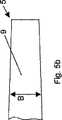
b)前端5に向かって幅Bが収斂する楔形(図5b);
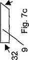
c)前端5に向かって幅Bが拡がる楔形(図5c);
d)平面図で見て刃9は前端5が凸面状に構成されている(図5d);
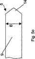
e)平面図で見て刃9は前端5が等辺または不等辺で尖端14となっている(図5e);
f)平面図で見て刃9は前端5が片側で斜めにされている(図5f);
g)平面図で見て刃9は前端5が片側で丸くされている(図5g);
h)側面32と平行に延びる縦断面において刃9は前端5が等辺または不等辺で尖っている(図6a);
i)側面32と平行に延びる縦断面において刃9は前端5が片側で斜めにされている(図6b);
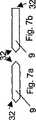
j)長手軸線4に垂直な横断面において刃9は側面32にある両方の側稜が尖端となる(図7a);
k)長手軸線4に垂直な横断面において刃9は側面32にある一つの側稜が尖端となる(図7b);
l)長手軸線4に垂直な横断面において刃9は側面32にある一つの側稜が斜めにされている(図7c);
m)長手軸線4に垂直な横断面において刃9は側面32にある両方の側稜が等しく斜めにされている(図7d);
n)長手軸線4に垂直な横断面において刃9は側面32にある両方の側稜が相逆向きに斜めにされている(図7e)。
【0022】
捩られた刃9の二つの実施形態が図8aと図8bに示してある。図8aが示す刃9は、側面32の一つに隣接して長さLを含む刃9の稜を中心に長さLにわたって捩り角αだけ捩られている。図8bが示す刃9は長手軸線4を中心に長さLにわたってやはり捩れ角αだけ捩られている。捩れは左捩りまたは右捩りとしておくことができる。捩れ長LV、捩れ角αの場合、捩りのピッチは以下のように定義することができる:
ピッチS=Lv*360°/α[°]
【0023】
刃9をこのように螺旋形に構成する場合、60mm〜300mm、好ましくは100mm〜240mmのピッチが有利である。
【0024】
図9aは刃9の組合せ体を有する係止要素3の他の実施形態を示す。この係止要素3は2枚の刃9を有する係止部分27を含み、係止要素3の全長にわたって長手軸線4と同軸に配置される中空体28によって刃は結合される。両方の刃9は、それらの第1横軸線29が一平面内にあるように配置されている。中空体28は長手軸線4と同軸で穴20が穿孔されている。
【0025】
係止要素3の図9bに示す実施形態は複数枚の刃9の他の組合せ体であり、この組合せ体は3枚の放射状に配置される刃9を含む。3枚の刃9の一つの側面32(図4)は長手軸線4と平行に同軸な中空円筒28に結合されており、刃9の第1横軸線29は長手軸線4を基準に中心角β、γ、δを成す。ここに示す実施形態において中心角β、γ、δは等しく、すなわちβ=γ=δであるが、他の実施形態において刃9は必要に応じてさまざまな中心角で配置しておくことができる。3枚以上の刃9を含む係止要素3は螺旋状に構成しておくこともできる。
【0026】
髄内釘システムの場合、刃形係止インプラントは打ち込まれる。脊柱の場合、打込みはきわめて重要な神経・血管構造を損傷する危険があるので厳禁である。
【0027】
送り装置15を利用して係止要素3を制御下に挿入する可能性が図10〜図13に示してある。図10に示す送り装置15が含む送りねじ16は、ねじ先端17と、ねじ軸部18と、ねじ先端17に隣接するねじ部分21と、駆動手段19とを有し、駆動手段19は係止要素3の後端6から操作可能である。送りねじ16は係止要素3に対して相対的に回転自在である。送りねじ16はねじ回し49で回されると骨内を螺旋状に動いて係止要素3を一緒に進める。
【0028】
ねじ部分21は図10と図11によれば係止部分27に一体化しておくことができ、ねじ山は刃9の厚さDから半径方向に張り出し、または係止要素3の前端5で係止部分27から末端側で突出する。さらに、ねじ部分21は長さLの一部にわたってのみまたは全長Lにわたって延設することができる。この送り装置15の利点は送りねじ16が係止部分27を直接に骨内に引き入れることにある。他方で欠点として椎体の中心で骨はごく多孔性であり、送りねじ16が空回りし、送り装置が機能しないことがある。
【0029】
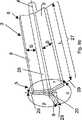
図12において送り装置15が含む送りねじ16は中空体28の穴20内で支承され、係止要素3の前端5から突出し、相手皮質骨内で係止可能である。送りねじ16の場合のようにねじを利用して相手皮質骨内で係止する代りに、延長部を有する他の要素、例えば栓46(図16aと図16b)またはフック47(図17aと図17b)等も利用できる。係止要素3の後端6に送り装置15は送りねじ16に結合された延長部63を有し、この延長部は長さ部分Aにわたって同軸で係止要素3から突出し、末端側に受け部50を有する。こうして受け部50と係止要素3の後端6との間に拡開装置51を介装することができ、係止部分27は拡開装置51の拡開によって骨内に押し込むことができる。送り装置15のこの実施形態の利点は、最良と考えられる骨内で送りねじ16が最初から係止されていることにある。他方で、大きさの制限から費用のかかる器具が必要とされるのが欠点である。
【0030】
図13に象徴的に示したU形補助装置48は、係止部分27を係止要素3の後端6で拡開装置51によって骨内に加圧するために例えば骨ねじ52によって皮質骨内で受け部として係止される。ここでは補助装置48を係止するのに椎体の付加的穿孔が不可欠となることが不利に作用する。
【0031】
骨ねじや中空ねじと比較して、刃9は長手軸線4における係止強度が比較的乏しい欠点を有する。図10〜図12に示す送り装置15が係止強度を高める。
【0032】
図14a〜図14cは、刃9の表面造形によって長手軸線4における係止強度を高めることのできる可能性を示す:
a)刃9の長さLと幅Bとによって限定された表面の鋸歯状構成(図14a)。その際、鋸歯の急峻な側は係止要素3の前端5とは逆の方を向いている;または
b)刃9の長さLと幅Bとによって限定された表面の鱗状構成(図14b)。ここでも鱗の急峻な側は係止要素3の前端5とは逆の方を向いている。
【0033】
鋸歯状構成または鱗状構成は長さLと幅Bとによって限定された表面の一方にのみまたはこれらの表面の両方に設け、長さLの一部のみを占め、または全長Lにわたって延設することができる。
c)機械的閉鎖の代りに生物学的閉鎖も利用可能である。図14cに示すようにこの場合刃9は長さLと幅Bとによって限定された表面に垂直に複数の孔62が穿孔され、骨は孔62内を成長できる。
【0034】
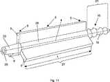
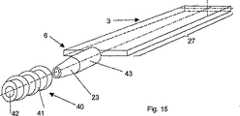
図15の実施形態において、雄ねじ41を有するねじ込筒体40が係止要素3の後端6に配置されている。ねじ込筒体40が含む同軸な穴42は係止部分27と末端側円錐部分23との間に配置される円筒心棒43上にずらすことができる。送りねじ16(図10〜図12)と同様に、このねじ込筒体40はやはり骨内で係止要素3の係止強度を高めるのに役立つ。この実施形態は図10〜図14に示す変種と組合せて応用することができる。
【0035】
送り装置16(図12)を相手皮質骨内で係止するための装置が図16aと図16bに示してあり、この装置は送りねじ15(図12)の代りに利用可能である。これは、その第1末端56および第2末端57の方から同軸な溝55によって半径方向で弾力的に構成された中空円筒形栓46である(図16a)。図16aの実施形態において栓46の半径方向拡開は、やはり同軸なねじ棒54上に同軸で配置される二つの拡開円錐体53を利用して行われる。この拡開円錐体53はねじ棒54上の雄ねじと拡開円錐体53内の雌ねじとによって互いに移動可能である。図16bに示すように、拡開円錐体53の代りに楔要素58も栓46の半径方向拡開に利用できる。ここに示した栓46は第2末端57の方からのみ同軸で設けられた溝55を有し、栓46の拡開はねじ棒54を利用して楔要素58を同軸で引き入れることによって行われる。楔要素58は図16bに示すような4部分構成の代りに1部分構成、2部分構成または3部分構成とすることもできる。
【0036】
送り装置16(図12)を相手皮質骨内で係止するための他の装置が図17aと図17bに示してある。これは係止要素3(図1)の長手軸線4を基準に半径方向で拡開するフック47であり、その先端61に向かって先細となり、組立前および組立中、同軸に配置される筒体59によって半径方向で圧縮される。フック47は同軸な棒60を利用して導入される。フック47の導入後、筒体59は先端61とは反対側の末端を介してフック47から引き離され、これによりフック47は半径方向で弾力的に拡開して相手皮質骨内で係止される。
【0037】
図18は係止要素3を挿入した椎体63の横断面図であり、この係止要素は長手軸線4が脊柱の長軸を横切って椎体63に通されている。
【0038】
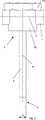
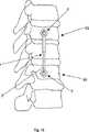
図19は本発明による装置を移植した複数の椎体63の側面図であり、この実施形態においてこの装置は中心軸線2を脊柱の長軸と平行にした一つの入れ子式長手材1と二つの係止要素3とを含む。
【図面の簡単な説明】
【図1】 本発明による装置の一実施形態の平面図である。
【図2】 本発明による装置の図1に示す実施形態の側面図である。
【図3】 本発明による装置の他の実施形態の側面図である。
【図4】 係止要素の一実施形態の斜視図である。
【図5】 a〜gは係止要素のさまざまな実施形態の平面図である。
【図6】 aとbは係止要素のさまざまな実施形態の側面図である。
【図7】 a〜eは係止要素のさまざまな実施形態の係止部分の横断面図である。
【図8】 aとbは係止要素のさまざまな実施形態における捩られた係止部分の斜視図である。
【図9】 aとbは係止要素のさまざまな実施形態における複数枚の刃からなる係止部分の斜視図である。
【図10】 送りねじを備えた螺旋形係止要素の一実施形態の斜視図である。
【図11】 3枚の刃を有する、送りねじを備えた係止要素の他の実施形態の斜視図である。
【図12】 送り装置を備えた係止要素の他の実施形態の斜視図である。
【図13】 送り装置で移植可能な係止要素の斜視図である。
【図14】 aは表面構造を有する係止要素の一実施形態の斜視図、bは表面構造を有する係止要素の別の実施形態の斜視図、cは横方向に延びる孔を有する係止要素の一実施形態の斜視図である。
【図15】 ねじ込筒体を備えた係止要素の一実施形態の斜視図である。
【図16】 aとbは係止要素を挿入するための送り装置を係止するための装置の斜視図である。
【図17】 aとbは係止要素を挿入するための送り装置を係止するための他の装置の斜視図である。
【図18】 係止要素を移植した椎体の横断面図である。
【図19】 本発明による装置を移植した脊柱の部分図である。[0001]
(Technical field)
The invention relates to a device according to the preamble of claim 1 for fixing bones, in particular vertebral bodies relative to one another.
[0002]
(Background technology)
Instability of spinal motion segments, which can be caused by vertebral fractures, degenerative changes, etc., often requires fusion of the segments. In order to achieve the fixation necessary for bone union of the motor segments to be fused, the segments are variously stabilized with a fixation system. These fixation systems can be inserted and locked from the back and locked with bone screws in the stalk, or inserted and locked from the front or the front and outside, and bone screws can be used in the vertebral body To either stop.
[0003]
The locking quality of the fixation system is strongly dependent on the quality of the bone structure. This is especially true in the case of a fastening system that is locked on the front and outside. The greater the degree of osteoporosis, the greater the risk that the bone screw will cut the bone already under a small load. The use of thick screws reduces the risk of cutting. On the other hand, however, you do not want to use screws that are too thick to avoid destroying the bone structure in the vertebral body too strongly.
[0004]
Solutions for reducing the risk of breaking the locking element are shown in DE 29600879 AESCULAP and WO 00/10473 AEBI. The problem here is basically the hollow screw that is screwed into the vertebral body. This hollow screw has the advantage that it has a large outer diameter without pushing much bone away. When screwed, a conical bone remains in the center of the hollow screw. The disadvantage of this solution is that
a) When screwing a hollow screw, the vascular distribution of the conical bone that remains in the center is largely destroyed, which can cause problems, especially in osteoporotic bones,
b) For bones where the repair mechanism is still functioning The hollow screw may become so firmly fixed that it becomes difficult to remove at the time of inspection or a large bone damage is caused at the time of removal (for example, a hollow inserted into the cervical spine). Some of the screws could no longer be removed).
[0005]
Intramedullary stabilization technology has been developed in connection with surgical treatment of tubular bone fractures, but this technology has been successfully used in the spinal column to solve the problem of locking the anterior and anterolateral spinal fixation systems it can.
[0006]
Intramedullary nails are used for splinting a fractured tubular bone by joining the proximal portion of the fractured tubular bone with the distal portion in the medulla. However, intramedullary nails can only absorb small rotational and axial loads due to their geometry. This is not a problem as long as the fractured bone can be maintained in height under an axial load and the fracture is more or less in the shaft. However, in the presence of multi-fragment fractures, the intramedullary nail must be locked proximally and distally. At the same time, the intramedullary nail no longer serves for splint fixation, but as a longitudinal member locked proximally and distally as in the vertebral column, this longitudinal member exerts forces and moments in all planes. Can be transmitted from the proximal side to the distal side. Locking implants, in the case of intramedullary nails, are screws threaded across the bone and intramedullary nail distally and proximally. In the case of osteoporosis or fractures close to the joint, locking of the intramedullary nail with screws is no longer sufficient. US3433220 ZICKEL, EP0411273 FRIGG, US4103683 NEUFELD, US4978349 FRIGG, DE4318150 FRIEDL, EP0491138 FRIGG, DE37030570 MATTHECK, WO98 / 30164 BRESINA, WO99 / 45858 HUNGERBUHLER and the spiral as used clinically Blade implants are unsuitable for use in the spinal column.
[0007]
(Disclosure of the Invention)
In this respect, the present invention is intended to provide a remedy. It is an object of the present invention to provide a spinal fixation device that can be secured to a vertebral body using a helically twisted blade-like locking element and that considers the following additional conditions:
a) setting the locking implant before inserting the longitudinal member, which eliminates the need for complex aiming devices and special alignment of the locking element with respect to the longitudinal member;
b) the longitudinal member is fitted to the end of the locking implant;
c) The joint between the longitudinal member and the locking implant can be locked in a multi-axial and angle-free manner without gaps and can be released again;
d) The locking element must be retractable by the feeder, which eliminates the need for uncontrolled driving.
[0008]
This object of the invention is solved with a fixation device having the features of claim 1 for fixing bones, in particular vertebral bodies, relative to one another.
[0009]
The device according to the invention for fixing bones, in particular vertebral bodies relative to one another, essentially comprises a longitudinal longitudinal member having a central axis, a longitudinal axis, a respective front end and a respective rear end. And n locking elements (2 ≦ j ≦ n). The longitudinal axis of the locking element can be arranged at an angle of preferably 65 ° to 115 ° with respect to the central axis of the longitudinal member, while the locking element is arranged in a blade shape adjacent to the rear end and towards the front end. ing. Each locking element includes at its rear end receiving means for a longitudinal member with retaining means operable from the rear end for releasably locking the joint between the longitudinal member and the locking element By this, a preferably angle-changeable connection of the locking element is achieved. A locked joint does not allow relative movement between the longitudinal member and the locking element and absorbs forces and moments in all three axial directions of the three-dimensional coordinate system.
[0010]
Depending on the embodiment of the receiving means, the angle between the longitudinal axis of the locking element and the central axis of the longitudinal member is fixed or can be changed about the axis or other implementations of the device according to the invention The configuration can be adjusted with multiple axes.
[0011]
The blade surface can again be configured differently on the side defined by the length L and width B, or on both sides defined by the length L and width B:
a) smooth surface;
b) have saw blades;
c) scales;
d) having a sagittal tooth;
e) rough surface (eg etching, plasma coating, blasting); or f) perforation (biological closure by bone growing in the hole).
[0012]
The surface structure can be provided on one side, on both sides, or only on part of the blade surface. Various configurations of the blade can be combined with various surfaces.
[0013]
The locking element can be inserted into the vertebral body by driving or using a feeding device. Uncontrolled implantation in the spine is generally undesirable (risk of damaging vital nerve and vascular structures). Possible feeding systems:
a) the lead screw is integrated with the blade (tip);
b) The elements (screws, plugs, hooks, etc., with extensions) that are locked in the cortical bone (Gegenkortikalis) serve as receptacles for drawing the blades into the bone; or c) Locked in cortical bone to pressurize into the bone.
[0014]
Other advantageous configurations of the invention are specified in the dependent claims.
Compared to a device locked to a vertebra through a screw, the present invention provides the following advantages:
1) The resistance to cutting in the bone is increased, and at the same time the bone mass displaced is reduced:
Same support area per unit length:
-Implants with two bone screws per vertebra and a core diameter d = 5 mm:
Support area per unit area: 2 × d × length / length = 10 mm2 / mm
Amount of displacement per unit length: 2 × d2 × Pi / 4 × length / length = 39 mm2 / mm
An implant with a blade-shaped locking element with a width per vertebra B = 10 mm, a central core diameter d = 5 mm and a blade thickness D = 1.2 mm:
Support area per unit area: 2 × d × length / length = 10 mm2 / mm
Amount of displacement per unit length: ((B−d) × H + d2 × Pi / 4) × length / length = 25.6 mm2 / mm
That is, a 34% reduction in displacement (excluding screws) results in the same support area.
[0015]
Same displacement per unit length (excluding screw):
-Implants with two bone screws per vertebra and a core diameter d = 5 mm:
Amount of displacement per unit length: 2 × d2 × Pi / 4 × length / length = 39 mm2 / mm
Supporting area per unit length: 2 × d × length / length = 10 mm2 / mm
-Width per vertebra B =? Implant having a blade-shaped locking element with mm, central core diameter d = 5 mm and blade thickness D = 1.2 mm:
Amount of displacement per unit length: ((B−d) × H + d2 × Pi / 4) × length / length = 39 mm2 / mm
Supporting area per unit length: ((39 mm2 −d2 × Pi / 4) / H + d) × length / length = 21 mm2 / mm
That is, a 110% increase in the support area results at the same displacement.
[0016]
2) A device locked in the vertebral body with a screw is combined with at least two bone screws per vertebra or one clasp-like substrate to achieve the rotational stability essential for healing. Requires bone screws. The blade-shaped locking element itself is rotationally locked in the bone, thus providing the rotational stability essential for the effective fusion of the bridging vertebral bodies with the following advantages:
The device coupled to the spinal column via one blade-shaped locking element on each of the cranial and caudal sides can be inserted into the spinal column at a higher position than a bulky implant locked via a screw;
-By reducing to one locking element per vertebra, assembly of the implant based on the blade-shaped locking element is simplified and facilitated.
[0017]
(Best Mode for Carrying Out the Invention)
In the following, the present invention and the constructions of the invention will be explained in more detail on the basis of partial schematic diagrams of several embodiments.
[0018]
The embodiment of the device according to the invention shown in FIGS. 1 and 2 includes a
[0019]
The locking
[0020]
2. locking element One embodiment of a locking
[0021]
a) a rectangular parallelepiped shape having a length L, a thickness D, and a width B (FIG. 5a);
b) a wedge shape with a width B converging towards the front end 5 (FIG. 5b);
c) a wedge shape with a width B increasing towards the front end 5 (FIG. 5c);
d) The
e) When viewed in plan view, the
f) The
g) The
h) In a longitudinal section extending parallel to the
i) In a longitudinal section extending parallel to the
j) In a cross section perpendicular to the
k) In a cross section perpendicular to the
l) In a cross section perpendicular to the
m) In a cross section perpendicular to the
n) In the cross-section perpendicular to the
[0022]
Two embodiments of the
Pitch S =Lv* 360 ° / α [°]
[0023]
When the
[0024]
FIG. 9 a shows another embodiment of the
[0025]
The embodiment shown in FIG. 9 b of the
[0026]
In the case of an intramedullary nail system, the blade locking implant is driven. In the case of the vertebral column, driving is strictly prohibited as it can damage vital nerve and vascular structures.
[0027]
The possibility of inserting the
[0028]
The
[0029]
In FIG. 12, the
[0030]
The U-shaped
[0031]
Compared with bone screws and hollow screws, the
[0032]
Figures 14a to 14c show the possibility that the locking strength at the
a) A serrated configuration of the surface defined by the length L and width B of the blade 9 (FIG. 14a). In so doing, the sharp side of the saw blade faces away from the
[0033]
The serrated or scale-like configuration is provided on only one or both of the surfaces defined by the length L and the width B, occupies only a part of the length L, or extends over the entire length L Can do.
c) Biological closure can also be used instead of mechanical closure. In this case, as shown in FIG. 14 c, the
[0034]
In the embodiment of FIG. 15, a threaded
[0035]
A device for locking the feed device 16 (FIG. 12) in the counterpart cortical bone is shown in FIGS. 16a and 16b, which can be used in place of the feed screw 15 (FIG. 12). This is a hollow
[0036]
Another device for locking the feeder 16 (FIG. 12) within the counterpart cortical bone is shown in FIGS. 17a and 17b. This is a
[0037]
FIG. 18 is a cross-sectional view of the
[0038]
FIG. 19 is a side view of a plurality of
[Brief description of the drawings]
FIG. 1 is a plan view of an embodiment of an apparatus according to the present invention.
FIG. 2 is a side view of the embodiment shown in FIG. 1 of an apparatus according to the present invention.
FIG. 3 is a side view of another embodiment of the device according to the invention.
FIG. 4 is a perspective view of one embodiment of a locking element.
FIGS. 5a-g are plan views of various embodiments of locking elements. FIG.
FIGS. 6a and 6b are side views of various embodiments of locking elements. FIGS.
FIGS. 7a-e are cross-sectional views of locking portions of various embodiments of locking elements. FIGS.
FIGS. 8a and 8b are perspective views of twisted locking portions in various embodiments of locking elements. FIGS.
FIGS. 9a and 9b are perspective views of a locking portion comprising a plurality of blades in various embodiments of locking elements. FIGS.
FIG. 10 is a perspective view of one embodiment of a helical locking element with a lead screw.
11 is a perspective view of another embodiment of a locking element with a lead screw having three blades. FIG.
FIG. 12 is a perspective view of another embodiment of a locking element with a feeding device.
13 is a perspective view of a locking element implantable with a feeder device. FIG.
14 is a perspective view of an embodiment of a locking element having a surface structure, b is a perspective view of another embodiment of a locking element having a surface structure, and c is a locking with a laterally extending hole. FIG. FIG. 6 is a perspective view of one embodiment of an element.
FIG. 15 is a perspective view of one embodiment of a locking element with a threaded barrel.
16 a and b are perspective views of a device for locking a feed device for inserting a locking element. FIG.
FIGS. 17a and b are perspective views of another device for locking a feeding device for inserting a locking element. FIGS.
FIG. 18 is a cross-sectional view of a vertebral body implanted with a locking element.
FIG. 19 is a partial view of a spinal column implanted with a device according to the present invention.
Claims (51)
Translated fromJapaneseA)中心軸線(2)を有する一つの縦方向長手材(1)と、
B)長手軸線(4)と各一つの前端(5)と各一つの後端(6)とを有するn個の係止要素(3.i)(2≦i≦n)とを含み、
C)係止要素(3.i)の長手軸線(4)が長手材(1)の中心軸線(2)に対して65°〜115°の角度にあり、
D)係止要素(3.j)(1≦j≦n)の少なくとも一つが刃形に構成されているものにおいて、
E)少なくともこの係止要素(3.j)が、長手材(1)と係止要素(3.j)との間の結合部を解除可能にロックするための保持手段(8;34)を有する長手材(1)用受容手段(7)を後端(6)に含み、
F)結合部がロックされた状態で、長手材(1)と係止要素(3.j)との間の相対運動を可能とせずかつ前記結合部は力およびモーメントを吸収し、
G)少なくとも一つの係止要素(3.j)が、係止要素(3.j)を長手軸線(4)と平行に骨に挿入するための送り装置(15)を含み、
H)前記送り装置は、前記係止要素(3.j)の後端(6)の方から操作可能な駆動手段(19)を備え、さらに、
i)送りねじ、または
ii)延長部付きのねじ、栓もしくはフックであって該延長部の末端側に受け部(50)を有するねじ、栓もしくはフックを備え、
I)係止要素(3.j)は連続した穴(20)を、該穴(20)の長手軸線(4)と同軸で有し、前記送り装置は前記穴(20)内に受容可能であることを特徴とする固定装置。A fixation device for fixing bones relative to each other,
A) one longitudinal longitudinal member (1) having a central axis (2);
B) n locking elements (3.i) (2 ≦ i ≦ n) having a longitudinal axis (4), each one front end (5) and each one rear end (6),
C) the longitudinal axis (4) of the locking element (3.1) is at an angle of 65 ° to 115 ° with respect to the central axis (2) of the longitudinal member (1);
D) In the case where at least one of the locking elements (3.j) (1 ≦ j ≦ n) is formed in a blade shape,
E) At least this locking element (3.j) has retaining means (8; 34) for releasably locking the joint between the longitudinal member (1) and the locking element (3.j) Comprising a receiving means (7) for the longitudinal member (1) at the rear end (6),
F) With thecoupling part locked, it does not allow relative movement between the longitudinal member (1) and the locking element (3.j) and thecoupling part absorbsforces and moments;
G) at least one locking element (3.j) comprises a feeding device (15) for inserting the locking element (3.j) into the bone parallel to the longitudinal axis (4);
H) The feeding device comprises drive means (19) operable from the rear end (6) of the locking element (3.j),
i) a lead screw, or ii) a screw, plug or hook with an extension, having a receptacle (50) on the distal side of the extension,
I) The locking element (3.j) has a continuous hole (20) coaxial with the longitudinal axis (4) of the hole (20), the feeding device being receivable in the hole (20). A fixing device characterized by being.
Applications Claiming Priority (1)
| Application Number | Priority Date | Filing Date | Title |
|---|---|---|---|
| PCT/CH2000/000654WO2002045606A1 (en) | 2000-12-08 | 2000-12-08 | Device for fixing bones, particularly vertebral bodies, in relation to one another |
Publications (2)
| Publication Number | Publication Date |
|---|---|
| JP2004513757A JP2004513757A (en) | 2004-05-13 |
| JP4588294B2true JP4588294B2 (en) | 2010-11-24 |
Family
ID=4358161
Family Applications (1)
| Application Number | Title | Priority Date | Filing Date |
|---|---|---|---|
| JP2002547394AExpired - Fee RelatedJP4588294B2 (en) | 2000-12-08 | 2000-12-08 | Fixation device for fixing bones, especially vertebral bodies relative to each other |
Country Status (16)
| Country | Link |
|---|---|
| US (2) | US20040068258A1 (en) |
| EP (1) | EP1339335B1 (en) |
| JP (1) | JP4588294B2 (en) |
| AR (1) | AR031616A1 (en) |
| AT (1) | ATE273661T1 (en) |
| AU (1) | AU2001216855A1 (en) |
| BR (1) | BR0017377B1 (en) |
| CA (1) | CA2433344C (en) |
| DE (1) | DE50007524D1 (en) |
| DK (1) | DK1339335T3 (en) |
| ES (1) | ES2223617T3 (en) |
| MX (1) | MXPA03004216A (en) |
| PT (1) | PT1339335E (en) |
| SI (1) | SI1339335T1 (en) |
| TR (1) | TR200402686T4 (en) |
| WO (1) | WO2002045606A1 (en) |
Families Citing this family (44)
| Publication number | Priority date | Publication date | Assignee | Title |
|---|---|---|---|---|
| WO2000015273A1 (en) | 1998-09-11 | 2000-03-23 | Gerhard Schmidmaier | Biologically active implants |
| US7901435B2 (en)* | 2004-05-28 | 2011-03-08 | Depuy Spine, Inc. | Anchoring systems and methods for correcting spinal deformities |
| ES2346670T3 (en)* | 2005-08-15 | 2010-10-19 | Synthes Gmbh | OSTEOSYNTHESIS DEVICE. |
| US7628799B2 (en) | 2005-08-23 | 2009-12-08 | Aesculap Ag & Co. Kg | Rod to rod connector |
| WO2007022790A1 (en)* | 2005-08-23 | 2007-03-01 | Synthes Gmbh | An osteosynthetic clamp for attaching a bone anchor to a support rod |
| US20070093813A1 (en)* | 2005-10-11 | 2007-04-26 | Callahan Ronald Ii | Dynamic spinal stabilizer |
| US20070093815A1 (en)* | 2005-10-11 | 2007-04-26 | Callahan Ronald Ii | Dynamic spinal stabilizer |
| US20070093814A1 (en)* | 2005-10-11 | 2007-04-26 | Callahan Ronald Ii | Dynamic spinal stabilization systems |
| US7833252B2 (en) | 2006-01-27 | 2010-11-16 | Warsaw Orthopedic, Inc. | Pivoting joints for spinal implants including designed resistance to motion and methods of use |
| US8057519B2 (en) | 2006-01-27 | 2011-11-15 | Warsaw Orthopedic, Inc. | Multi-axial screw assembly |
| US7722652B2 (en) | 2006-01-27 | 2010-05-25 | Warsaw Orthopedic, Inc. | Pivoting joints for spinal implants including designed resistance to motion and methods of use |
| WO2007124099A2 (en)* | 2006-04-21 | 2007-11-01 | Synthes (U.S.A) | Hip helical implant |
| JP5406022B2 (en)* | 2006-06-12 | 2014-02-05 | スミス アンド ネフュー インコーポレーテッド | Tibial resection system, method and apparatus |
| US7806913B2 (en)* | 2006-08-16 | 2010-10-05 | Depuy Spine, Inc. | Modular multi-level spine stabilization system and method |
| US20090088782A1 (en)* | 2007-09-28 | 2009-04-02 | Missoum Moumene | Flexible Spinal Rod With Elastomeric Jacket |
| US9232968B2 (en)* | 2007-12-19 | 2016-01-12 | DePuy Synthes Products, Inc. | Polymeric pedicle rods and methods of manufacturing |
| CA2781407A1 (en) | 2008-01-14 | 2009-07-23 | Michael P. Brenzel | Apparatus and methods for fracture repair |
| US20090326583A1 (en)* | 2008-06-25 | 2009-12-31 | Missoum Moumene | Posterior Dynamic Stabilization System With Flexible Ligament |
| US20090326584A1 (en)* | 2008-06-27 | 2009-12-31 | Michael Andrew Slivka | Spinal Dynamic Stabilization Rods Having Interior Bumpers |
| US8641734B2 (en)* | 2009-02-13 | 2014-02-04 | DePuy Synthes Products, LLC | Dual spring posterior dynamic stabilization device with elongation limiting elastomers |
| US9408715B2 (en) | 2009-04-15 | 2016-08-09 | DePuy Synthes Products, Inc. | Arcuate fixation member |
| US8641766B2 (en)* | 2009-04-15 | 2014-02-04 | DePuy Synthes Products, LLC | Arcuate fixation member |
| US9320543B2 (en)* | 2009-06-25 | 2016-04-26 | DePuy Synthes Products, Inc. | Posterior dynamic stabilization device having a mobile anchor |
| RU2712028C2 (en)* | 2009-11-09 | 2020-01-24 | Спайнуэлдинг Аг | Medical device for implantation into human or animal body or for strengthening of human or animal solid tissue for further implantation of separate implant and dental implant |
| US20110178520A1 (en) | 2010-01-15 | 2011-07-21 | Kyle Taylor | Rotary-rigid orthopaedic rod |
| WO2011091052A1 (en) | 2010-01-20 | 2011-07-28 | Kyle Taylor | Apparatus and methods for bone access and cavity preparation |
| WO2011112615A1 (en) | 2010-03-08 | 2011-09-15 | Krinke Todd A | Apparatus and methods for securing a bone implant |
| US9445844B2 (en) | 2010-03-24 | 2016-09-20 | DePuy Synthes Products, Inc. | Composite material posterior dynamic stabilization spring rod |
| US9358122B2 (en) | 2011-01-07 | 2016-06-07 | K2M, Inc. | Interbody spacer |
| US9980824B2 (en)* | 2014-09-03 | 2018-05-29 | Globus Medical, Inc. | Intervertebral implants and related methods of use |
| US11123117B1 (en)* | 2011-11-01 | 2021-09-21 | Nuvasive, Inc. | Surgical fixation system and related methods |
| US9050137B2 (en)* | 2012-06-04 | 2015-06-09 | Virak Orthopedic Research Llc | Interchangeable orthopedic blade |
| CN105939677A (en) | 2013-12-12 | 2016-09-14 | 康文图斯整形外科公司 | Tissue displacement tools and methods |
| US10045803B2 (en) | 2014-07-03 | 2018-08-14 | Mayo Foundation For Medical Education And Research | Sacroiliac joint fusion screw and method |
| CA2917676A1 (en) | 2015-01-13 | 2016-07-13 | Stryker European Holdings I, Llc | Growing rods and methods of use |
| EP3273889B1 (en)* | 2015-03-25 | 2020-12-02 | Pier Giovanni Menci | Intramedullary nail for the treatment of fractures of long bones |
| US10413332B2 (en) | 2016-04-25 | 2019-09-17 | Imds Llc | Joint fusion implant and methods |
| US9833321B2 (en) | 2016-04-25 | 2017-12-05 | Imds Llc | Joint fusion instrumentation and methods |
| WO2019010252A2 (en) | 2017-07-04 | 2019-01-10 | Conventus Orthopaedics, Inc. | APPARATUS AND METHODS FOR TREATING BONES |
| US11446064B2 (en) | 2018-04-26 | 2022-09-20 | Stryker European Operations Holdings Llc | Orthopedic growing devices |
| DE102019000965B4 (en) | 2019-02-09 | 2020-12-24 | Mimeo Medical Gmbh | Bone anchoring device for pedicle access |
| WO2020171849A1 (en)* | 2019-02-24 | 2020-08-27 | Blue Sky Technologies, LLC | Implant for bone |
| DE102020004184A1 (en) | 2020-07-11 | 2022-01-13 | Mimeo Medical Gmbh | Blade type osteosynthesis device |
| US12035928B2 (en)* | 2021-11-12 | 2024-07-16 | NextWave Medical, LLC | Devices and methods for correction of hip deformities |
Family Cites Families (19)
| Publication number | Priority date | Publication date | Assignee | Title |
|---|---|---|---|---|
| US3025853A (en)* | 1958-07-07 | 1962-03-20 | Christopher A Mason | Fixation device for fractured femur |
| US3433220A (en) | 1966-12-30 | 1969-03-18 | Robert E Zickel | Intramedullary rod and cross-nail assembly for treating femur fractures |
| US4103683A (en) | 1977-06-03 | 1978-08-01 | Neufeld John A | Sub-trochanteric nail |
| US4710075A (en)* | 1986-10-01 | 1987-12-01 | Boehringer Mannheim Corporation | Adjustable drill gauge |
| FR2650173B1 (en) | 1989-07-26 | 1991-11-15 | Jbs Sa | METHOD AND DEVICE FOR STRAIGHTENING, FIXING, COMPRESSION, ELONGATION OF THE RACHIS |
| US4978349A (en) | 1989-08-03 | 1990-12-18 | Synthes (U.S.A.) | Fixation plate |
| CH682300A5 (en)* | 1990-12-17 | 1993-08-31 | Synthes Ag | |
| DE4318150C2 (en) | 1993-06-01 | 1996-08-01 | Endocare Ag | Osteosynthesis tools for the treatment of subtrochanteric and pertrochanteric fractures as well as fractures of the femoral neck |
| JP3308271B2 (en)* | 1992-06-25 | 2002-07-29 | ジンテーズ アクチエンゲゼルシャフト,クール | Osteosynthesis fixation device |
| US5888221A (en)* | 1992-08-11 | 1999-03-30 | Gelbard; Steven D. | Spinal stabilization implant system |
| JPH08257034A (en)* | 1995-03-18 | 1996-10-08 | Ee & F:Kk | Internal fixation member for pediatric femoral osteotomy / cervical fracture treatment and its driving method |
| US5688273A (en)* | 1995-10-23 | 1997-11-18 | Fastenetix, Llc. | Spinal implant apparatus having a single central rod and plow hooks |
| DE29600879U1 (en) | 1996-01-19 | 1996-03-28 | Howmedica GmbH, 24232 Schönkirchen | Spinal implant |
| EP0917449B1 (en)* | 1996-07-31 | 2003-02-05 | Synthes Ag Chur | Device for attaching fractured hip-joint heads |
| US5741256A (en)* | 1997-01-13 | 1998-04-21 | Synthes (U.S.A.) | Helical osteosynthetic implant |
| WO1998031293A1 (en)* | 1997-01-14 | 1998-07-23 | Synthes Ag Chur | Pedicle screw with double thread |
| DE19720782B4 (en) | 1997-05-17 | 2004-12-09 | Synthes Ag Chur, Chur | Device for connecting a side member to a pedicle screw |
| JP3172703B2 (en)* | 1997-12-18 | 2001-06-04 | 株式会社ロバート・リード商会 | Bone fixation device |
| DE59804611D1 (en) | 1998-08-21 | 2002-08-01 | Synthes Ag | SELF-CUTTING HOLLOW CYLINDRICAL BONE ANCHORING ELEMENT |
- 2000
- 2000-12-08TRTR2004/02686Tpatent/TR200402686T4/enunknown
- 2000-12-08EPEP00979310Apatent/EP1339335B1/ennot_activeExpired - Lifetime
- 2000-12-08MXMXPA03004216Apatent/MXPA03004216A/enunknown
- 2000-12-08ATAT00979310Tpatent/ATE273661T1/ennot_activeIP Right Cessation
- 2000-12-08PTPT00979310Tpatent/PT1339335E/enunknown
- 2000-12-08AUAU2001216855Apatent/AU2001216855A1/ennot_activeAbandoned
- 2000-12-08DKDK00979310Tpatent/DK1339335T3/enactive
- 2000-12-08WOPCT/CH2000/000654patent/WO2002045606A1/ennot_activeApplication Discontinuation
- 2000-12-08CACA002433344Apatent/CA2433344C/ennot_activeExpired - Fee Related
- 2000-12-08ESES00979310Tpatent/ES2223617T3/ennot_activeExpired - Lifetime
- 2000-12-08SISI200030507Tpatent/SI1339335T1/enunknown
- 2000-12-08BRBRPI0017377-0Apatent/BR0017377B1/ennot_activeIP Right Cessation
- 2000-12-08DEDE50007524Tpatent/DE50007524D1/ennot_activeExpired - Lifetime
- 2000-12-08JPJP2002547394Apatent/JP4588294B2/ennot_activeExpired - Fee Related
- 2001
- 2001-10-05ARARP010104695Apatent/AR031616A1/enactiveIP Right Grant
- 2003
- 2003-06-09USUS10/456,535patent/US20040068258A1/ennot_activeAbandoned
- 2006
- 2006-07-13USUS11/485,833patent/US7666207B2/ennot_activeExpired - Lifetime
Also Published As
| Publication number | Publication date |
|---|---|
| ATE273661T1 (en) | 2004-09-15 |
| DE50007524D1 (en) | 2004-09-23 |
| PT1339335E (en) | 2005-01-31 |
| ES2223617T3 (en) | 2005-03-01 |
| CA2433344C (en) | 2009-05-19 |
| SI1339335T1 (en) | 2005-02-28 |
| BR0017377B1 (en) | 2008-11-18 |
| AR031616A1 (en) | 2003-09-24 |
| EP1339335A1 (en) | 2003-09-03 |
| US20060271053A1 (en) | 2006-11-30 |
| EP1339335B1 (en) | 2004-08-18 |
| US7666207B2 (en) | 2010-02-23 |
| TR200402686T4 (en) | 2004-11-22 |
| CA2433344A1 (en) | 2002-06-13 |
| WO2002045606A1 (en) | 2002-06-13 |
| BR0017377A (en) | 2003-09-16 |
| HK1055663A1 (en) | 2004-01-21 |
| JP2004513757A (en) | 2004-05-13 |
| DK1339335T3 (en) | 2004-11-15 |
| US20040068258A1 (en) | 2004-04-08 |
| AU2001216855A1 (en) | 2002-06-18 |
| MXPA03004216A (en) | 2003-09-22 |
Similar Documents
| Publication | Publication Date | Title |
|---|---|---|
| JP4588294B2 (en) | Fixation device for fixing bones, especially vertebral bodies relative to each other | |
| EP3773281B1 (en) | Threaded implants for use across bone segments | |
| EP2242437B1 (en) | Facet fixation prosthesis | |
| US8951295B2 (en) | Posterior spinal fastener | |
| US9060809B2 (en) | Lagwire system and method for the fixation of bone fractures | |
| JP4131989B2 (en) | Helical osteosynthesis graft | |
| US10363074B2 (en) | Dynamic axial nail for intramedullary treatment of long bone fractures | |
| US20110034925A1 (en) | Lagwire system and method for the fixation of bone fractures | |
| US20120089195A1 (en) | System and method for self filling bone screws | |
| US20120184993A1 (en) | Expandable facet screw | |
| US20100312292A1 (en) | Lagwire system and method for the fixation of bone fractures | |
| US20120035667A1 (en) | Locking mechanisms for pivoting bone anchors | |
| EP2326271A1 (en) | Dynamic pedicle screw | |
| GB2154296A (en) | Sacral fixation screw | |
| JP4918091B2 (en) | Osteosynthesis device | |
| US11000326B1 (en) | Orthopedic fastener and associated systems and methods | |
| US20150112393A1 (en) | Lateral plate for spinal fusion | |
| JP2004527284A (en) | Fixing screw | |
| WO2025096361A1 (en) | Devices and methods for anterior transpedicular fixation and posterior revision | |
| HK1055663B (en) | Device for fixing bones, particularly vertebral bodies, in relation to one another | |
| CZ20031544A3 (en) | Devices for fastening bones, especially vertebrae, to each other |
Legal Events
| Date | Code | Title | Description |
|---|---|---|---|
| A711 | Notification of change in applicant | Free format text:JAPANESE INTERMEDIATE CODE: A711 Effective date:20061219 | |
| A621 | Written request for application examination | Free format text:JAPANESE INTERMEDIATE CODE: A621 Effective date:20071202 | |
| RD02 | Notification of acceptance of power of attorney | Free format text:JAPANESE INTERMEDIATE CODE: A7422 Effective date:20080117 | |
| A131 | Notification of reasons for refusal | Free format text:JAPANESE INTERMEDIATE CODE: A131 Effective date:20081210 | |
| A601 | Written request for extension of time | Free format text:JAPANESE INTERMEDIATE CODE: A601 Effective date:20090306 | |
| A602 | Written permission of extension of time | Free format text:JAPANESE INTERMEDIATE CODE: A602 Effective date:20090313 | |
| A601 | Written request for extension of time | Free format text:JAPANESE INTERMEDIATE CODE: A601 Effective date:20090403 | |
| A602 | Written permission of extension of time | Free format text:JAPANESE INTERMEDIATE CODE: A602 Effective date:20090410 | |
| A601 | Written request for extension of time | Free format text:JAPANESE INTERMEDIATE CODE: A601 Effective date:20090428 | |
| A602 | Written permission of extension of time | Free format text:JAPANESE INTERMEDIATE CODE: A602 Effective date:20090511 | |
| A521 | Request for written amendment filed | Free format text:JAPANESE INTERMEDIATE CODE: A523 Effective date:20090610 | |
| A131 | Notification of reasons for refusal | Free format text:JAPANESE INTERMEDIATE CODE: A131 Effective date:20090911 | |
| A601 | Written request for extension of time | Free format text:JAPANESE INTERMEDIATE CODE: A601 Effective date:20091209 | |
| A602 | Written permission of extension of time | Free format text:JAPANESE INTERMEDIATE CODE: A602 Effective date:20091222 | |
| A601 | Written request for extension of time | Free format text:JAPANESE INTERMEDIATE CODE: A601 Effective date:20100107 | |
| A601 | Written request for extension of time | Free format text:JAPANESE INTERMEDIATE CODE: A601 Effective date:20100208 | |
| A521 | Request for written amendment filed | Free format text:JAPANESE INTERMEDIATE CODE: A523 Effective date:20100310 | |
| A602 | Written permission of extension of time | Free format text:JAPANESE INTERMEDIATE CODE: A602 Effective date:20100310 | |
| TRDD | Decision of grant or rejection written | ||
| A01 | Written decision to grant a patent or to grant a registration (utility model) | Free format text:JAPANESE INTERMEDIATE CODE: A01 Effective date:20100811 | |
| A01 | Written decision to grant a patent or to grant a registration (utility model) | Free format text:JAPANESE INTERMEDIATE CODE: A01 | |
| A61 | First payment of annual fees (during grant procedure) | Free format text:JAPANESE INTERMEDIATE CODE: A61 Effective date:20100908 | |
| R150 | Certificate of patent or registration of utility model | Free format text:JAPANESE INTERMEDIATE CODE: R150 | |
| FPAY | Renewal fee payment (event date is renewal date of database) | Free format text:PAYMENT UNTIL: 20130917 Year of fee payment:3 | |
| LAPS | Cancellation because of no payment of annual fees |