JP4587583B2 - Control method for chromatographic separation - Google Patents
Control method for chromatographic separationDownload PDFInfo
- Publication number
- JP4587583B2 JP4587583B2JP2001060436AJP2001060436AJP4587583B2JP 4587583 B2JP4587583 B2JP 4587583B2JP 2001060436 AJP2001060436 AJP 2001060436AJP 2001060436 AJP2001060436 AJP 2001060436AJP 4587583 B2JP4587583 B2JP 4587583B2
- Authority
- JP
- Japan
- Prior art keywords
- fluid
- packed bed
- bed
- supplying
- adsorbent
- Prior art date
- Legal status (The legal status is an assumption and is not a legal conclusion. Google has not performed a legal analysis and makes no representation as to the accuracy of the status listed.)
- Expired - Fee Related
Links
Images


Landscapes
- Treatment Of Liquids With Adsorbents In General (AREA)
Description
Translated fromJapanese【0001】
【発明の属する技術分野】
本発明は、クロマト分離方法に関するものであり、詳しくは、2以上の成分を含む混合流体を、各成分が富化された2以上の画分にクロマト分離する方法の制御方法に関するものである。
【0002】
【従来の技術】
固体吸着剤を用いるクロマト分離法は、工業的に広く実施されており、2成分以上の混合物から、各成分が富化された画分をクロマト分離により取得する方法も種々提案されている。
クロマト分離方法において、特に擬似移動床方式は分離性能に優れ、生産性が高い点から工業的に広く採用されている。この方式では、充填床への原料流体や脱着剤の供給は所定の流速で行われ、また充填床内を移動する流体も所定流速で流れている。しかしながら、擬似移動床方式は複雑な装置を必要とし、充填床への原料流体や脱着剤の供給、更には充填床内を循環する流体の移動等にかなり高度な制御技術が必要とされる。
【0003】
一方、より簡単な装置で良好な分離成績を上げることができるクロマト分離方法も、特開昭63−158105、特開平2−049159などに示されている。例えば、特開昭63−158105には、原料流体を供給する工程、脱着剤流体を供給する工程及び充填床内の流体を循環する工程の少なくとも3つの工程からなるサイクルを反復するクロマト分離法が開示されている。
擬似移動床法では、充填床内に形成されている濃度の分布は、マクロ的にみるとほぼ一定の形をしており、経時的にその濃度分布がその形状を維持したままで充填床内を循環的に移動している。従って、充填床内の液を移動させるために必要な圧力、つまり充填床内の液を移動させる時に発生する圧力損失は、どの時間帯でもほぼ等しいと言える。この様な場合には、前述のような流速を一定に制御する方法により、再現性良く装置の運転制御が行われ、所望の分離性能を得ることが出来る。
【0004】
一方、特開昭63−158105でも、原料流体、脱着流体の供給や充填床内の液を移動させる際には、流速を所定流速に制御すると共に、工程の切り換えを所定の時間が経過した時に行うようにして制御する方法が用いられている。しかし、この方法の場合、充填床内の各成分の濃度及び充填床内に形成される濃度分布は、各工程で経時とともに変わり、逐次変化している。即ち、原料流体が供給され、特定の成分が富化された液が抜き出される原料供給工程においては、その供給開始時点から終了時点までの間で充填床内の成分の濃度は逐次増加し、また、脱着剤が供給され、別の特定の成分が富化された液が抜き出される脱着剤供給工程においては、その開始時点から終了時点までの間で充填床内の成分の濃度は逐次減少している。更に、液の供給と抜き出しを行わず、充填床内の流体を循環的に移動させ、複数成分混在帯域を充填床の前端に移動させる工程においても、その開始時点から終了時点までの間、充填床内の濃度分布は逐次変化するのである。
【0005】
クロマト分離の対象として最も一般的な原料流体は各種の糖液類であるが、糖液類は濃度によって粘性が大きく異なり高濃度の糖液類は高粘性を呈する。従って、原料流体が糖液類のように、その濃度によって粘性が大きく異なる流体である場合には、充填床内に存在する成分の濃度やその分布が変化すると、充填床内の流体を移動させるために必要とされる圧力も変化する。換言すれば、充填床内の流体を移動させる時に発生する圧力損失が、逐次変化していく。
尚、本明細書中において、「糖液類」とは、糖類、糖アルコール、澱粉やイヌリンなどの加水分解物成分等を含む液体を総称するものである。
【0006】
この圧力損失の変化を詳細に解析してみると、複数成分を含む原料流体が供給される原料供給工程では、供給される原料流体よりも濃度が低く、且つ特定の成分が富化された液が抜出されているので、この工程の段階においては、充填床内に存在する流体中の原料成分の平均的な濃度は逐次増加していることになる。また、脱着剤を供給して、別の特定の成分に富化された液を抜出す工程では、脱着剤よりも抜出される流体の濃度が高いことが明らかであり、このことは脱着剤を供給して、別の特定の成分に富化された液を抜出す工程においては、充填床内に存在する流体中の原料成分の平均的な濃度は逐次減少していることを意味するのである。
従って、充填床内の流体を移動させるために必要とされる圧力は、一般的に供給工程の終了付近において最大値に達し、脱着剤を供給する工程の終了付近において最小値となる。
【0007】
特開昭63−158105号に記載のようなクロマト分離方法においては、原料流体、脱着剤流体の供給、並びに充填床内の流体の循環的移動手段としては、ポンプを使用し、前述のように単位時間当たりのポンプの吐出流量、すなわち流速を所定流速に制御することによって運転制御がなされているが、ポンプの揚程は、原料供給工程の終了付近の最大圧力値以上の能力を有するように設定する必要がある。一方、脱着剤を供給する工程においては、ポンプは、原料供給工程の終了付近で必要とされるほどの揚程は要しない。そこで、脱着剤の供給時には、過剰の圧力を制御弁などにより消費することにより、所定の流体の流量となるように制御されている。
【0008】
また、充填床を収容する容器の耐圧性能も、原料供給工程の終了付近の最大圧力に耐えられる強度を有する必要があるが、脱着剤を供給する工程においては、容器は、これほどの耐圧性能を必要としない。
この様に、従来の上記クロマト分離方法においては、ポンプの単位時間当たりの吐出流量を所定流量に制御することにより運転しているので、当該ポンプの揚程能力および充填床を収容する容器の耐圧能力を遭遇する最大圧力以上に設定する必要があるが、原料供給工程においては、その能力は充分に活用されるものの、この工程以外の時間帯においては過剰能力となり、当該装置の製作価格の高騰化の原因および運転経費の増加の原因となる。
【0009】
【発明が解決しようとする課題】
本発明は、特開昭63−158105号に示されるような、充填床内の原料成分の濃度及びその濃度分布が周期的に変化するクロマト分離方法により、複数成分を含む混合物から各成分の富化された画分を分離する方法を実施する際の改善された運転制御手法を提供することを目的とするものである。
【0010】
【課題を解決するための手段】
本発明は、当該クロマト分離方法における原料流体、脱着剤流体、及び充填床内の流体の循環的移動を、単位時間当たりのポンプの吐出流量を所定値に制御する方法に代え、ポンプの充填床へ供給される流体の圧力を一定に制御する方法で行うものであり、その要旨は次の通りである。
吸着剤が充填された充填床の前端と後端が流体通路で連結され流体の循環を可能にしたクロマト分離系に、吸着剤に対する親和性が異なる複数の成分を含む原料流体を供給し、充填床の前端から後端の方向に床内を流通させて各成分の濃度分布を有する吸着帯域を形成させたのち2以上の画分に分離する方法であって、少なくとも、
(i)充填床前端から原料流体を供給しつつ、充填床後端から任意の一成分が富化された画分を抜き出す工程、
(ii)充填床前端から脱着剤流体を供給して充填床後端から他の成分が富化された画分を抜き出す工程、
(iii)充填床への流体の供給及び充填床からの流体の抜き出しを行わずに床内の流体を循環させ、(i)の工程で抜き出された成分と他の成分が混在する帯域を充填床の前端に移動させる工程、
の各工程を任意の順序で含むサイクルを繰り返すことよりなるクロマト分離方法において、原料流体、脱着剤流体及び循環流体の移送ポンプの充填床へ供給される流体の圧力を一定に制御し運転することを特徴とするクロマト分離の制御方法。
【0011】
【発明の実施の形態】
本発明を以下詳細に説明する。
特開昭63−158105号に示されるような、原料流体が間欠的に供給され、かつ充填床内に原料流体の成分が常に存在するクロマト分離方法では、基本的には以下に示す(i)、(ii)、(iii)を含む複数の工程を1サイクルとし、このサイクルを繰り返すことにより行われる。
(i)充填床前端から原料流体を供給しつつ、充填床後端から任意の一成分が富化された画分を抜き出す工程(供給工程と略称)、
(ii)充填床前端から脱着剤流体を供給して充填床後端から他の成分が富化された画分を抜き出す工程(脱着工程と略称)、
(iii)充填床への流体の供給及び充填床からの流体の抜き出しを行わずに床内の流体を循環させ、(i)の工程で抜き出された成分と他の成分が混在する帯域を充填床の前端に移動させる工程(循環工程と略称)。
【0012】
本発明に係わるクロマト分離方法では、分離対象とする原料の含有成分に応じて、上記(i)〜(iii)の各工程、更にはこれに付加工程を適宜組み合わせたサイクルを繰り返すことにより行われるが、分離に使用されるクロマト分離装置の一例を図1に示す。図中、1及び2は吸着剤が充填された充填床であり、各充填床の容量は等しくても異なっていても良い。3は原料流体タンク、4は脱着剤流体タンクを表し、5〜9は各画分の抜き出しラインを表す。10〜19は各ラインに設けられた開閉弁を表し、20は原料流体、脱着剤流体及び循環流体の移送用ポンプを表す。
このような装置を用いるクロマト分離法においては、充填床内の各成分の濃度及びその分布は、時間とともに変化する。
即ち、各成分の濃度は、供給工程において、原料流体の供給開始時点から終了時点までの間逐次増加し、供給工程の終了時にその濃度は最大になる。また、脱着工程においても、脱着剤の供給開始時点から終了時点までの間成分濃度は次第に低下し、終了時点で最低になる。更に、循環工程においては、全体としての成分濃度そのものは変化しないが、その開始時点から終了時点までの間、各成分は移動するにつれ充填床内で相互に分離し、その濃度分布は逐次変化する。
従って、上記のクロマト分離法では、供給工程と脱着工程が行われるので、充填床内に原料流体の成分が高濃度で存在する状態と低濃度で存在する状態が現出することになる。
【0013】
ところが、クロマト分離に供される原料流体が各種の糖液類のように、その濃度によって粘性が大きく異なる流体である場合は、充填床に存在する成分の濃度やその分布が変化することは、換言すれば、充填床を流体が一定の流速で移動する場合に必要な圧力が逐次変化することであり、充填床内を流体が一定の流速で移動する時に発生する圧力損失が、逐次変化していることを意味する。そして、糖液類の成分が最も高濃度で存在する供給工程の終了時点では、それ以前と同じ流速で流体を移動させると充填床に高い圧力損失を生じさせることになる。
【0014】
この圧力損失の変化を詳細にみると、原料流体の供給工程では、供給される原料流体よりも濃度の低い特定の成分に富化された液が抜出されているので、この工程においては、充填床内に存在する原料流体の各成分の平均的な濃度は逐次増加し、工程終了時点で最高濃度に達することを意味する。また、原料流体の供給工程に引き続いて脱着剤を供給する脱着工程が行われる場合には、抜出される流体は脱着剤よりもその成分濃度が高いことから充填床内に存在する原料流体の平均的な成分濃度は逐次減少していることが明らかである。この事は、充填床内を流体を一定の流速で移動させる場合の圧力は、供給工程の終了付近において最大値に達し、脱着工程の開始と共に低下し始めその終了付近において最小値となることを意味する。
【0015】
図1に示すクロマト分離装置を用いて分離方法を行う場合、従来は、単位時間当たりのポンプの吐出流量、すなわち流速を所定値に制御する方法で行われている。この場合、ポンプの揚程は、供給工程の終了付近で達する最大圧力値以上の能力を有するように設定されている。一方、脱着剤を供給する脱着工程では、流体を所定の流速で移動させるのに要する圧力が供給工程における圧力よりも低いので、供給工程と同じ流速で流体を移動させる場合は、当該ポンプには、供給工程の終了付近で必要とするほどの揚程は要らず、圧力は過剰となる。
このことは、言い換えれば、流速を所定値に制御するいわゆる定流速制御では供給工程終了付近以外の時間帯においては、ポンプの過剰の揚程能力を制御弁などにより消費して、その消費圧力と流体の移動に必要な圧力との和がポンプの揚程能力と等しくなるように制御して稼働させることになる。
【0016】
このように、供給工程で要する圧力に応じた揚程能力に設計されたポンプは、供給工程終了付近以外の時間帯では能力的に過剰となっているので、本発明ではこの過剰の能力を工程の全時間帯に亘って有効に活用するため、定流速制御の代わりにポンプから充填床に供給される流体の圧力を一定とする定出制御を行う。これによりポンプを常に最大能力で作動させることになり極めて効率的となる。そして、供給工程終了付近以外の時間帯においては、従来の流速を所定値に制御する定流速制御を行っている場合よりもより大きな流速で流体を移動させることが出来るのである。
【0017】
本発明方法では、この制御方法を行うことにより、原料流体の供給を始めてから、次サイクルの供給工程を開始するまでに要する時間、即ち、1サイクルに要する時間は、従来の流速を所定値に制御する、所謂定流速制御方法の場合よりも短くなる。1サイクル当たりに処理される原料流体の量は一定なので、本発明方法により、定圧制御を行う場合は、1サイクルの所用時間が短くなるので、クロマト分離装置の単位時間当たりの処理量は増加することになる。
【0018】
更に、本発明方法ではクロマト分離法の1サイクルの各工程の切り換えを、時間ではなくポンプの吐出液量が所定値に達した時、即ち、ポンプから吐出される液量を積算して、これが所定の値に達した時に行うことにより、更に効率的に操作することが可能となる。
なお、充填床を収容する容器の耐圧能力は、ポンプの揚程能力に応じて設計製作されているので、ポンプをその持つ揚程能力で常時運転しても何らの支障はない。
【0019】
本発明によれば、既存のクロマト分離装置の場合、1サイクル当たりの所要時間が短縮されるので、より生産性を高めることが出来る。また、クロマト分離装置を新設する場合には、装置の小型化が可能なので、本発明方法はクロマト分離装置の建設費の低減化を可能にする利点を有する。
【0020】
本発明方法は、複数成分を含みクロマト分離が可能な種々の混合物に適用することができる。対象とする混合物の代表的なものは糖液類であり、例えば、種々の糖類、或いは糖アルコールの混合物等が挙げられ、具体的には異性化糖からの果糖の分離、異性化糖からのオリゴ糖の分離、糖蜜からの蔗糖の分離、マルトース、マルトデキストリン等を含む澱粉の加水分解物からの各成分の分離、フラクトース、イヌロビオースなどを含むイヌリンの加水分解物からの各成分の分離、イソマルトース及びイソマルトースデキストリンを含む混合物からの各成分の分離、ソルビトール、マルチトールなどの糖アルコールを含む混合物からの各成分の分離等に適用することができる。
【0021】
充填床に使用される吸着剤の代表的なものとしては、イオン交換樹脂が挙げられる。具体的にはNa,K等のアルカリ金属塩形、又はCa等のアルカリ土類金属塩形の強酸性カチオン交換樹脂が挙げられる。
【0022】
本発明は、特開昭63−158105号に示される前記(i)〜(iii)の基本的工程に、更に分離される被対象物及び分離条件に応じて付加工程を加えたより多数工程からなる分離方法を実施する場合にも適用することが出来、その実施態様例を示せば以下の通りである。
▲1▼ 吸着剤が充填された充填床の前端と後端が流体通路で連結され流体の循環を可能にしたクロマト分離系に、吸着剤に対する親和性が異なる複数の成分を含む原料流体を供給し、充填床の前端から後端の方向に床内を流通させて各成分の濃度分布を有する吸着帯域を形成させたのち2以上の画分に分離するクロマト分離方法において、
(i)充填床前端から原料流体を供給しつつ、充填床後端から吸着剤に対する親和性が高い成分が富化された画分を抜き出す工程、
(ii)充填床前端から脱着剤流体を供給して充填床後端から吸着剤に対する親和性が低い成分が富化された画分を抜き出す工程、
(iii)充填床への流体の供給及び充填床からの流体の抜き出しを行わずに床内の流体を循環させ、吸着剤に対する親和性が高い成分と吸着剤に対する親和性が低い成分が混在する帯域を充填床の前端に移動させる工程、
の各工程を繰り返すことにより混合物を2つの画分に分離する方法。
【0023】
▲2▼ 上記▲1▼に記載のクロマト分離方法において、
(i)充填床前端から原料流体を供給しつつ、充填床後端から吸着剤に対する親和性が高い成分が富化された画分を抜き出す工程、
(ii)充填床前端から脱着剤流体を供給して充填床後端から吸着剤に対する親和性が高い成分が富化された画分を抜き出す工程、
(iii)充填床前端から脱着剤流体を供給して充填床後端から吸着剤に対する親和性が低い成分が富化された画分を抜き出す工程、
(iv)充填床への流体の供給及び充填床からの流体の抜き出しを行わずに床内の流体を循環させ、吸着剤に対する親和性が高い成分と吸着剤に対する親和性が低い成分が混在する帯域を充填床の前端に移動させる工程、
の各工程を繰り返すことにより混合物を2つの画分に分離する方法。
【0024】
▲3▼ 上記▲1▼に記載のクロマト分離方法において、
(i)充填床前端から原料流体を供給しつつ、充填床後端から吸着剤に対する親和性が高い成分が富化された画分を抜き出す工程、
(ii)充填床中間部から脱着剤流体を供給して充填床後端から吸着剤に対する親和性が高い成分が富化された画分をさらに抜き出す工程、
(iii)充填床への流体の供給及び充填床からの流体の抜き出しを行わずに床内の流体を循環させ、吸着剤に対する親和性が高い成分と吸着剤に対する親和性が低い成分が混在する帯域を充填床の前端に移動させる工程、
(iv)充填床前端から脱着剤流体を供給して充填床後端から吸着剤に対する親和性が低い成分が富化された画分を抜き出す工程、
(v)充填床への流体の供給及び充填床からの流体の抜き出しを行わずに床内の流体を循環させ、吸着剤に対する親和性が高い成分と吸着剤に対する親和性が低い成分が混在する帯域を充填床の前端に移動させる工程、
の各工程を繰り返すことにより混合物を2つの画分に分離する方法。
【0025】
▲4▼ 上記▲1▼に記載のクロマト分離方法において、
(i)充填床前端から原料流体を供給しつつ、充填床後端から吸着剤に対する親和性が低い成分が富化された画分を抜き出す工程、
(ii)充填床への流体の供給及び充填床からの流体の抜き出しを行わずに床内の流体を循環させ、吸着剤に対する親和性が高い成分と吸着剤に対する親和性が低い成分が混在する帯域を充填床の前端に移動させる工程、
(iii)充填床前端から脱着剤流体を供給して充填床後端から吸着剤に対する親和性が高い成分が富化された画分を抜き出す工程、
の各工程を繰り返すことにより混合物を2つの画分に分離する方法。
【0026】
▲5▼ 上記▲1▼に記載のクロマト分離方法において、
(i)充填床前端から原料流体を供給しつつ、充填床後端から吸着剤に対する親和性が2番目に高い成分が富化された画分を抜き出す工程、
(ii)充填床への流体の供給及び充填床からの流体の抜き出しを行わずに床内の流体を循環させ、吸着剤に対する親和性が2番目に高い成分と吸着剤に対する親和性が最も高い成分が混在する帯域を充填床の前端に移動させる工程、
(iii)充填床前端から脱着剤流体を供給して充填床後端から吸着剤に対する親和性が最も高い成分が富化された画分を抜き出す工程、
(iv)充填床前端から脱着剤流体を供給して充填床後端から吸着剤に対する親和性が最も低い成分が富化された画分を抜き出す工程、
(v)充填床への流体の供給及び充填床からの流体の抜き出しを行わずに床内の流体を循環させ、吸着剤に対する親和性が2番目に高い成分と吸着剤に対する親和性が最も低い成分が混在する帯域を充填床の前端に移動させる工程、
の各工程を繰り返すことにより混合物を3つの画分に分離する方法。
【0027】
▲6▼ 上記▲1▼に記載のクロマト分離方法において、
(i)充填床前端から原料流体を供給しつつ、充填床後端から吸着剤に対する親和性が2番目に高い成分が富化された画分を抜き出す工程、
(ii)充填床中間部から脱着剤流体を供給して充填床後端から吸着剤に対する親和性が2番目に高い成分が富化された画分をさらに抜き出す工程、
(iii)充填床への流体の供給及び充填床からの流体の抜き出しを行わずに床内の流体を循環させ、吸着剤に対する親和性が2番目に高い成分と吸着剤に対する親和性が最も高い成分が混在する帯域を充填床の前端に移動させる工程、
(iv)充填床前端から脱着剤流体を供給して充填床後端から吸着剤に対する親和性が最も高い成分が富化された画分を抜き出す工程、
(v)充填床前端から脱着剤流体を供給して充填床後端から吸着剤に対する親和性が最も低い成分が富化された画分を抜き出す工程、
(vi)充填床への流体の供給及び充填床からの流体の抜き出しを行わずに床内の流体を循環させ、吸着剤に対する親和性が2番目に高い成分と吸着剤に対する親和性が最も低い成分が混在する帯域を充填床の前端に移動させる工程、
の各工程を繰り返すことにより混合物を3つの画分に分離する方法。
【0028】
▲7▼ 上記▲1▼に記載のクロマト分離方法において、
(i)充填床前端から原料流体を供給しつつ、充填床後端から吸着剤に対する親和性が2番目に高い成分が富化された画分を抜き出す工程、
(ii)充填床前端から原料流体をさらに供給しつつ、充填床中間部から吸着剤に対する親和性が最も低い成分が富化された画分を抜き出す工程、
(iii)充填床への流体の供給及び充填床からの流体の抜き出しを行わずに床内の流体を循環させ、吸着剤に対する親和性が2番目に高い成分と吸着剤に対する親和性が最も高い成分が混在する帯域を充填床の前端に移動させる工程、
(iv)充填床前端から脱着剤流体を供給して充填床後端から吸着剤に対する親和性が最も高い成分が富化された画分を抜き出す工程、
(v)充填床前端から脱着剤流体を供給して充填床後端から吸着剤に対する親和性が最も低い成分が富化された画分を抜き出す工程、
(vi)充填床への流体の供給及び充填床からの流体の抜き出しを行わずに床内の流体を循環させ、吸着剤に対する親和性が2番目に高い成分と吸着剤に対する親和性が最も低い成分が混在する帯域を充填床の前端に移動させる工程、
の各工程を繰り返すことにより混合物を3つの画分に分離する方法。
【0029】
▲8▼ 上記▲1▼に記載のクロマト分離方法において、
(i)充填床前端から原料流体を供給しつつ、充填床後端から吸着剤に対する親和性が2番目に高い成分が富化された画分を抜き出す工程、
(ii)充填床中間部から脱着剤流体を供給して充填床後端から吸着剤に対する親和性が2番目に高い成分が富化された画分を抜き出す工程、
(iii)充填床への流体の供給及び充填床からの流体の抜き出しを行わずに床内の流体を循環させ、吸着剤に対する親和性が2番目に高い成分と吸着剤に対する親和性が最も高い成分が混在する帯域を充填床の前端に移動させる工程、
(iv)充填床前端から脱着剤流体を供給して充填床後端から吸着剤に対する親和性が最も高い成分が富化された画分を抜き出す工程、
(v)充填床前端から脱着剤流体を供給して充填床後端から吸着剤に対する親和性が最も低い成分が富化された画分を抜き出す工程、
(vi)充填床前端から脱着剤流体を供給して充填床後端から吸着剤に対する親和性が3番目に高い成分が富化された画分を抜き出す工程、
(vii)充填床への流体の供給及び充填床からの流体の抜き出しを行わずに床内の流体を循環させ、吸着剤に対する親和性が2番目に高い成分と吸着剤に対する親和性が3番目に高い成分が混在する帯域を充填床の前端に移動させる工程、
の各工程を繰り返すことにより混合物を4つの画分に分離する方法。
【0030】
なお、本発明は、特開昭62−91205、特開平1−80409、特開平4−227804、特開平4−334503、特開平4−367701、特開平11−267404特開平11−183459、特開平4−363102などに記載されているような、1サイクルにおいて、限定された時間帯のみ原料流体を供給し特定の成分に富化された流体を抜き出し、他の時間帯では原料流体の供給は行わず、脱着剤の供給により特定の成分に富化された流体を抜き出し、また流体の循環移動を行うクロマト分離の方法においても適用できることは勿論である。
【0031】
【実施例】
次に本発明を実施例により更に具体的に説明するが、本発明はその要旨を越えない限り以下の実施例に限定されるものではない。
実施例1
図1に示した装置を用いて、表−1に示す組成の原料(糖アルコール混合物)のクロマト分離を、吸着剤としてCa塩形の強酸性カチオン樹脂(ダイヤイオンUBK-535;三菱化学社製、登録商標)を使用し、脱着剤として水を使用して行った。内径102.3mm、充填高1,500mmの直列に連結した2本1組として、合計2組のカラムに吸着剤を合計49.3リットル充填した充填床を80℃に保ち、ポンプから充填床に供給される流体の圧力を0.5MPaに調整して通液し、表−2に示す液量で分離操作を繰り返し行った。
【0032】
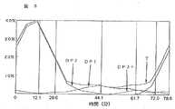
12サイクル目で図2に示す流出曲線が得られ、定常状態となった。図2において縦軸は流出液中の各成分の濃度(wt%)、横軸は時間(分)を表し、曲線はそれぞれDP1(ソルビトール)成分、DP2(マルチトール)成分、DP3+(3糖類以上の糖アルコール)成分の濃度分布曲線を示し、Tは全糖濃度(各成分濃度の合計)曲線を示す。定常状態到達後の各画分の成分組成と各成分の回収率を表−1に示す。この時、原料供給工程の終了付近で、容積流速は約26L/hrを示し、脱着工程の終了付近では約32L/hrを示した。また、1サイクルの所用時間は71.4分間であった。
【0033】
【表1】
【表2】
比較例1
表−1に示す原料のクロマト分離を、実施例1と同様な装置を使用し、ポンプから充填床に供給される流体の圧力を一定に調整せず、床内を容積流量26.3L/hrに調整して通液した以外は実施例1と同様として操作し、表−2に示す液量で分離操作を繰り返し行った。
12サイクル目で図3に示す流出曲線が得られ、定常状態となった。定常状態到達後の各画分の成分組成と各成分の回収率を表−3に示す。この時、原料供給工程の終了付近で、ポンプ吐出圧力は約0.5MPaを示し、脱着工程の終了付近では約0.3MPaを示した。また、1サイクルの所用時間は78.6分間であった
DP2の回収率は「比較例」がやや有利であるが、ほぼ同等の品質のDP2画分が得られたものの、1サイクルの時間が約10%長く、「実施例1」に比べ、原料処理能力が約1割低い結果となった。
【0036】
【表3】
【発明の効果】
本発明方法によれば、同一の装置において1サイクルに要する時間が、従来の定流量制御方法の場合よりも短くなるのでクロマト分離装置の単位時間当たりの処理量は、同一の吸着剤を充填した容器により構成されたクロマト分離装置においては、向上することになり、また対象物の処理量が一定の場合には、クロマト分離装置の吸着剤を充填する容器の容量は少なくて良く、クロマト分離装置の建設費の低減化を可能にする利点を有する。更に、流体の移送ポンプは一定圧力の条件下で変動することなく作動するので、安定した運転が可能となる。
【図面の簡単な説明】
【図1】図1は、本発明方法を実施するのに用いられるクロマト分離装置の一例である。
【図2】図2は、実施例1のクロマト分離における充填床内から流出する液体の各成分の濃度変化を示す一例であり、縦軸は各成分の濃度(wt%)、横軸は時間(分)を表す。
【図3】図3は、比較例1のクロマト分離における充填床内から流出する液体の各成分の濃度変化を示す一例であり、縦軸は各成分の濃度(wt%)、横軸は時間(分)を表す。
【符号の説明】
1,2 充填床
3 原料タンク
4 脱着剤タンク
5〜9 画分抜き出しライン
10〜19 開閉弁
20 移送用ポンプ[0001]
BACKGROUND OF THE INVENTION
The present invention relates to a chromatographic separation method, and more particularly, to a control method of a method for chromatographic separation of a mixed fluid containing two or more components into two or more fractions enriched with each component.
[0002]
[Prior art]
A chromatographic separation method using a solid adsorbent is widely practiced industrially, and various methods for obtaining a fraction enriched in each component from a mixture of two or more components by chromatographic separation have been proposed.
In the chromatographic separation method, in particular, the simulated moving bed method is widely used industrially because of its excellent separation performance and high productivity. In this system, the supply of the raw material fluid and the desorbent to the packed bed is performed at a predetermined flow rate, and the fluid moving in the packed bed is also flowing at the predetermined flow rate. However, the simulated moving bed system requires a complicated apparatus, and requires a considerably advanced control technique for supplying a raw material fluid and a desorbent to the packed bed, and for moving a fluid circulating in the packed bed.
[0003]
On the other hand, a chromatographic separation method capable of improving a good separation result with a simpler apparatus is also disclosed in JP-A-63-158105, JP-A-2-059159, and the like. For example, JP-A-63-158105 discloses a chromatographic separation method in which a cycle consisting of at least three steps of supplying a raw material fluid, supplying a desorbent fluid, and circulating the fluid in the packed bed is repeated. It is disclosed.
In the simulated moving bed method, the concentration distribution formed in the packed bed has a substantially constant shape when viewed macroscopically, and the concentration distribution in the packed bed maintains its shape over time. Is moving cyclically. Accordingly, it can be said that the pressure required to move the liquid in the packed bed, that is, the pressure loss generated when moving the liquid in the packed bed is almost equal in any time zone. In such a case, the operation control of the apparatus is performed with good reproducibility by the method of controlling the flow rate constant as described above, and a desired separation performance can be obtained.
[0004]
On the other hand, in Japanese Patent Laid-Open No. 63-158105, when supplying a raw material fluid, a desorbing fluid, or moving a liquid in a packed bed, the flow rate is controlled to a predetermined flow rate, and the process is switched when a predetermined time has elapsed. The method of controlling as it is done is used. However, in the case of this method, the concentration of each component in the packed bed and the concentration distribution formed in the packed bed change with time in each step and sequentially change. That is, in the raw material supply process in which a raw material fluid is supplied and a liquid enriched with a specific component is extracted, the concentration of the components in the packed bed increases sequentially from the supply start time to the end time, In addition, in the desorbent supply process in which the desorbent is supplied and the liquid enriched with another specific component is withdrawn, the concentration of the components in the packed bed gradually decreases from the start point to the end point. is doing. Furthermore, in the process of moving the fluid in the packed bed cyclically and moving the multi-component mixed zone to the front end of the packed bed without supplying and withdrawing liquid, filling is performed from the start point to the end point. The concentration distribution in the floor changes sequentially.
[0005]
The most common raw material fluids for chromatographic separation are various sugar solutions, but the viscosity of sugar solutions varies greatly depending on the concentration, and high concentration sugar solutions exhibit high viscosity. Therefore, when the raw material fluid is a fluid whose viscosity varies greatly depending on its concentration, such as sugar liquids, the fluid in the packed bed is moved when the concentration or distribution of components existing in the packed bed changes. The pressure required for this also changes. In other words, the pressure loss generated when moving the fluid in the packed bed changes sequentially.
In the present specification, “sugar liquids” is a generic term for liquids containing saccharides, sugar alcohols, hydrolyzate components such as starch and inulin, and the like.
[0006]
When the change in the pressure loss is analyzed in detail, in the raw material supply process in which the raw material fluid containing a plurality of components is supplied, the liquid is lower in concentration than the supplied raw material fluid and enriched with specific components. In this stage of the process, the average concentration of the raw material components in the fluid existing in the packed bed is successively increased. In addition, in the step of supplying the desorbing agent and extracting the liquid enriched in another specific component, it is clear that the concentration of the fluid to be extracted is higher than that of the desorbing agent. In the process of supplying and withdrawing the liquid enriched with another specific component, it means that the average concentration of the raw material components in the fluid existing in the packed bed is decreasing successively. .
Therefore, the pressure required to move the fluid in the packed bed generally reaches a maximum value near the end of the supply process, and reaches a minimum value near the end of the process of supplying the desorbent.
[0007]
In the chromatographic separation method as described in JP-A-63-158105, a feed fluid, a desorbent fluid, and a circulating means for circulating the fluid in the packed bed are used as described above. Operation control is performed by controlling the discharge flow rate of the pump per unit time, that is, the flow rate to a predetermined flow rate, but the pump head is set to have a capacity equal to or greater than the maximum pressure value near the end of the raw material supply process. There is a need to. On the other hand, in the step of supplying the desorbent, the pump does not require a lift as much as required near the end of the raw material supply step. Therefore, when supplying the desorbent, excessive pressure is consumed by a control valve or the like to control the flow rate of a predetermined fluid.
[0008]
In addition, the pressure resistance of the container that accommodates the packed bed needs to be strong enough to withstand the maximum pressure near the end of the raw material supply process, but in the process of supplying the desorbent, the container has such pressure resistance performance. Do not need.
Thus, in the conventional chromatographic separation method, since the pump is operated by controlling the discharge flow rate per unit time of the pump to a predetermined flow rate, the pump head capacity of the pump and the pressure resistance capacity of the container containing the packed bed are as follows. It is necessary to set the pressure higher than the maximum pressure encountered, but in the raw material supply process, its capacity is fully utilized, but it becomes excessive capacity in other time zones, and the production cost of the equipment increases. Cause an increase in operating costs.
[0009]
[Problems to be solved by the invention]
According to the present invention, as shown in JP-A-63-158105, the concentration of raw material components in a packed bed and the chromatographic separation method in which the concentration distribution changes periodically, the richness of each component from a mixture containing a plurality of components is achieved. It is an object of the present invention to provide an improved operation control method in carrying out the method for separating the fractionated fraction.
[0010]
[Means for Solving the Problems]
The present invention replaces the cyclic movement of the raw material fluid, the desorbent fluid, and the fluid in the packed bed in the chromatographic separation method with a method of controlling the discharge flow rate of the pump per unit time to a predetermined value. This method is performed by a method of controlling the pressure of the fluid supplied to the tank at a constant level, and the gist thereof is as follows.
Supply the raw fluid containing multiple components with different affinity to the adsorbent to the chromatographic separation system where the front and rear ends of the packed bed filled with the adsorbent are connected by a fluid passage to enable circulation of the fluid. A method of separating the two or more fractions after forming an adsorption zone having a concentration distribution of each component by passing through the bed in the direction from the front end to the rear end of the bed,
(I) extracting a fraction enriched with any one component from the back end of the packed bed while supplying the raw material fluid from the front end of the packed bed;
(Ii) supplying a desorbent fluid from the front end of the packed bed and extracting a fraction enriched with other components from the rear end of the packed bed;
(Iii) Circulating the fluid in the bed without supplying the fluid to the packed bed and extracting the fluid from the packed bed, and a zone where the component extracted in the step (i) and other components are mixed Moving to the front end of the packed bed,
In a chromatographic separation method comprising repeating a cycle including the steps in any order, the pressure of the fluid supplied to the packed bed of the transfer pump of the raw material fluid, the desorbent fluid and the circulating fluid is controlled to be constant. A control method for chromatographic separation characterized by the above.
[0011]
DETAILED DESCRIPTION OF THE INVENTION
The present invention is described in detail below.
In a chromatographic separation method in which a raw material fluid is intermittently supplied and components of the raw material fluid are always present in a packed bed as disclosed in JP-A-63-158105, basically, the following (i) A plurality of processes including (ii) and (iii) are defined as one cycle, and this cycle is repeated.
(I) A step of extracting a fraction enriched with an arbitrary component from the rear end of the packed bed while supplying the raw material fluid from the front end of the packed bed (abbreviated as a supply step),
(Ii) supplying a desorbent fluid from the front end of the packed bed and extracting a fraction enriched with other components from the rear end of the packed bed (abbreviated as a desorption step);
(Iii) Circulating the fluid in the bed without supplying the fluid to the packed bed and extracting the fluid from the packed bed, and a zone where the component extracted in the step (i) and other components are mixed A step of moving to the front end of the packed bed (abbreviated as a circulation step).
[0012]
In the chromatographic separation method according to the present invention, the steps (i) to (iii) are repeated according to the components contained in the raw material to be separated, and further by repeating a cycle in which additional steps are appropriately combined. FIG. 1 shows an example of a chromatographic separation apparatus used for separation. In the figure, 1 and 2 are packed beds filled with an adsorbent, and the capacity of each packed bed may be equal or different. 3 represents a raw material fluid tank, 4 represents a desorbent fluid tank, and 5 to 9 represent extraction lines for each fraction.
In the chromatographic separation method using such an apparatus, the concentration and distribution of each component in the packed bed change with time.
That is, the concentration of each component increases sequentially from the supply start time to the end time of the raw material fluid in the supply process, and the concentration becomes maximum at the end of the supply process. Also in the desorption process, the component concentration gradually decreases from the start of supply of the desorbent to the end, and becomes the lowest at the end. Furthermore, in the circulation process, the overall component concentration itself does not change, but from the start point to the end point, each component is separated from each other in the packed bed as it moves, and its concentration distribution changes sequentially. .
Therefore, in the above-described chromatographic separation method, since the supply step and the desorption step are performed, a state in which the components of the raw material fluid are present at a high concentration and a state at a low concentration appear in the packed bed.
[0013]
However, when the raw material fluid used for chromatographic separation is a fluid whose viscosity varies greatly depending on its concentration, such as various sugar liquids, the concentration and distribution of components present in the packed bed change, In other words, the pressure required when the fluid moves through the packed bed at a constant flow rate changes sequentially, and the pressure loss that occurs when the fluid moves through the packed bed at a constant flow rate changes sequentially. Means that Then, at the end of the supplying step in which the sugar liquid components are present at the highest concentration, if the fluid is moved at the same flow rate as before, a high pressure loss is generated in the packed bed.
[0014]
Looking at this change in pressure loss in detail, in the raw material fluid supply process, a liquid enriched in a specific component having a lower concentration than the supplied raw material fluid is extracted. The average concentration of each component of the feed fluid present in the packed bed increases sequentially, meaning that the maximum concentration is reached at the end of the process. In addition, when a desorption step for supplying a desorbent is performed subsequent to the feed step for the raw material fluid, the extracted fluid has a higher component concentration than the desorbent, so the average of the raw material fluids present in the packed bed It is clear that the typical component concentration decreases successively. This means that the pressure when moving the fluid in the packed bed at a constant flow rate reaches a maximum value near the end of the supply process, starts to decrease with the start of the desorption process, and reaches a minimum value near the end. means.
[0015]
In the case of performing the separation method using the chromatographic separation apparatus shown in FIG. 1, conventionally, the method is performed by controlling the discharge flow rate of the pump per unit time, that is, the flow rate to a predetermined value. In this case, the pump head is set to have a capacity equal to or higher than the maximum pressure value reached near the end of the supply process. On the other hand, in the desorption process for supplying the desorbent, the pressure required to move the fluid at a predetermined flow rate is lower than the pressure in the supply process. The lift is not necessary near the end of the supply process, and the pressure is excessive.
In other words, in so-called constant flow rate control that controls the flow rate to a predetermined value, the pump's excess head capacity is consumed by a control valve or the like in a time zone other than near the end of the supply process, and its consumption pressure and fluid It is controlled and operated so that the sum of the pressure required for the movement of the pump becomes equal to the pump head capacity.
[0016]
As described above, the pump designed for the head capacity corresponding to the pressure required in the supply process is excessive in the time zone other than near the end of the supply process. In order to make effective use over the entire time period, constant control is performed in which the pressure of the fluid supplied from the pump to the packed bed is constant, instead of constant flow rate control. This makes the pump always operating at maximum capacity and is extremely efficient. In a time zone other than the vicinity of the end of the supply process, the fluid can be moved at a larger flow velocity than when the conventional flow velocity control for controlling the flow velocity to a predetermined value is performed.
[0017]
In the method of the present invention, by performing this control method, the time required from the start of the supply of the raw material fluid to the start of the supply process of the next cycle, that is, the time required for one cycle is the conventional flow rate set to a predetermined value. This is shorter than in the case of the so-called constant flow rate control method. Since the amount of the raw material fluid processed per cycle is constant, when the constant pressure control is performed by the method of the present invention, the required time for one cycle is shortened, so that the throughput per unit time of the chromatographic separation apparatus increases. It will be.
[0018]
Further, according to the method of the present invention, switching of each process of one cycle of the chromatographic separation method is performed when the amount of liquid discharged from the pump reaches a predetermined value instead of time, that is, the amount of liquid discharged from the pump is integrated. By performing when the predetermined value is reached, it becomes possible to operate more efficiently.
In addition, since the pressure resistance capacity of the container that accommodates the packed bed is designed and manufactured according to the head capacity of the pump, there is no problem even if the pump is always operated with the head capacity.
[0019]
According to the present invention, in the case of an existing chromatographic separation apparatus, the required time per cycle is shortened, so that productivity can be further increased. In addition, when a chromatographic separation apparatus is newly installed, the apparatus can be downsized, and thus the method of the present invention has an advantage that the construction cost of the chromatographic separation apparatus can be reduced.
[0020]
The method of the present invention can be applied to various mixtures containing a plurality of components and capable of chromatographic separation. Typical examples of the target mixture are sugar liquids, for example, various sugars or a mixture of sugar alcohols, specifically, separation of fructose from isomerized sugar, and separation from isomerized sugar. Separation of oligosaccharide, separation of sucrose from molasses, separation of each component from hydrolyzate of starch containing maltose, maltodextrin, etc., separation of each component from hydrolyzate of inulin including fructose, inulobiose, The present invention can be applied to separation of each component from a mixture containing maltose and isomaltose dextrin, separation of each component from a mixture containing a sugar alcohol such as sorbitol and maltitol, and the like.
[0021]
Typical examples of the adsorbent used for the packed bed include ion exchange resins. Specific examples include strongly acidic cation exchange resins in the form of alkali metal salts such as Na and K, or alkaline earth metal salts such as Ca.
[0022]
The present invention comprises a larger number of steps in which an additional step is added to the basic steps (i) to (iii) described in JP-A-63-158105, depending on the object to be separated and separation conditions. The present invention can also be applied to the case where the separation method is performed, and an embodiment example thereof is as follows.
(1) Supply a raw material fluid containing a plurality of components with different affinities for the adsorbent to the chromatographic separation system in which the front and rear ends of the packed bed filled with the adsorbent are connected by a fluid passage to enable circulation of the fluid. Then, in the chromatographic separation method of separating into two or more fractions after forming an adsorption zone having a concentration distribution of each component through the bed in the direction from the front end to the rear end of the packed bed,
(I) extracting a fraction enriched with a component having high affinity for the adsorbent from the rear end of the packed bed while supplying the raw material fluid from the front end of the packed bed;
(Ii) supplying a desorbent fluid from the front end of the packed bed and extracting a fraction enriched with components having low affinity for the adsorbent from the rear end of the packed bed;
(Iii) The fluid in the bed is circulated without supplying the fluid to the packed bed and without extracting the fluid from the packed bed, so that a component having a high affinity for the adsorbent and a component having a low affinity for the adsorbent are mixed. Moving the zone to the front end of the packed bed;
A method of separating the mixture into two fractions by repeating each step of
[0023]
(2) In the chromatographic separation method described in (1) above,
(I) extracting a fraction enriched with a component having high affinity for the adsorbent from the rear end of the packed bed while supplying the raw material fluid from the front end of the packed bed;
(Ii) supplying a desorbent fluid from the front end of the packed bed and extracting a fraction enriched with components having high affinity for the adsorbent from the rear end of the packed bed;
(Iii) supplying a desorbent fluid from the front end of the packed bed and extracting a fraction enriched with components having low affinity for the adsorbent from the rear end of the packed bed;
(Iv) The fluid in the bed is circulated without supplying the fluid to the packed bed and without extracting the fluid from the packed bed, so that a component having a high affinity for the adsorbent and a component having a low affinity for the adsorbent are mixed. Moving the zone to the front end of the packed bed;
A method of separating the mixture into two fractions by repeating each step of
[0024]
(3) In the chromatographic separation method described in (1) above,
(I) extracting a fraction enriched with a component having high affinity for the adsorbent from the rear end of the packed bed while supplying the raw material fluid from the front end of the packed bed;
(Ii) supplying a desorbent fluid from the middle of the packed bed and further extracting a fraction enriched with components having high affinity for the adsorbent from the rear end of the packed bed;
(Iii) The fluid in the bed is circulated without supplying the fluid to the packed bed and without extracting the fluid from the packed bed, so that a component having a high affinity for the adsorbent and a component having a low affinity for the adsorbent are mixed. Moving the zone to the front end of the packed bed;
(Iv) supplying a desorbent fluid from the front end of the packed bed and extracting a fraction enriched with components having low affinity for the adsorbent from the rear end of the packed bed;
(V) The fluid in the bed is circulated without supplying the fluid to the packed bed and without extracting the fluid from the packed bed, so that a component having a high affinity for the adsorbent and a component having a low affinity for the adsorbent are mixed. Moving the zone to the front end of the packed bed;
A method of separating the mixture into two fractions by repeating each step of
[0025]
(4) In the chromatographic separation method described in (1) above,
(I) extracting a fraction enriched with components having low affinity for the adsorbent from the back end of the packed bed while supplying the raw material fluid from the front end of the packed bed;
(Ii) The fluid in the bed is circulated without supplying the fluid to the packed bed and without extracting the fluid from the packed bed, and a component having a high affinity for the adsorbent and a component having a low affinity for the adsorbent are mixed. Moving the zone to the front end of the packed bed;
(Iii) supplying a desorbent fluid from the front end of the packed bed and extracting a fraction enriched with components having high affinity for the adsorbent from the rear end of the packed bed;
A method of separating the mixture into two fractions by repeating each step of
[0026]
(5) In the chromatographic separation method described in (1) above,
(I) extracting a fraction enriched with a component having the second highest affinity for the adsorbent from the rear end of the packed bed while supplying the raw material fluid from the front end of the packed bed;
(Ii) The fluid in the bed is circulated without supplying the fluid to the packed bed and without extracting the fluid from the packed bed, and the component having the second highest affinity for the adsorbent and the highest affinity for the adsorbent. Moving the zone where the components are mixed to the front end of the packed bed,
(Iii) supplying a desorbent fluid from the front end of the packed bed and extracting a fraction enriched with a component having the highest affinity for the adsorbent from the rear end of the packed bed;
(Iv) supplying a desorbent fluid from the front end of the packed bed and extracting a fraction enriched with a component having the lowest affinity for the adsorbent from the rear end of the packed bed;
(V) The fluid in the bed is circulated without supplying the fluid to the packed bed and without extracting the fluid from the packed bed, and the component having the second highest affinity for the adsorbent and the lowest affinity for the adsorbent. Moving the zone where the components are mixed to the front end of the packed bed,
A method of separating the mixture into three fractions by repeating each step of
[0027]
(6) In the chromatographic separation method described in (1) above,
(I) extracting a fraction enriched with a component having the second highest affinity for the adsorbent from the rear end of the packed bed while supplying the raw material fluid from the front end of the packed bed;
(Ii) supplying a desorbent fluid from the middle of the packed bed and further extracting from the rear end of the packed bed a fraction enriched with a component having the second highest affinity for the adsorbent;
(Iii) The fluid in the bed is circulated without supplying the fluid to the packed bed and without extracting the fluid from the packed bed, and the component having the second highest affinity for the adsorbent and the highest affinity for the adsorbent. Moving the zone where the components are mixed to the front end of the packed bed,
(Iv) supplying a desorbent fluid from the front end of the packed bed and extracting a fraction enriched with components having the highest affinity for the adsorbent from the rear end of the packed bed;
(V) supplying a desorbent fluid from the front end of the packed bed and extracting a fraction enriched with a component having the lowest affinity for the adsorbent from the rear end of the packed bed;
(Vi) The fluid in the bed is circulated without supplying the fluid to the packed bed and without extracting the fluid from the packed bed, and the component having the second highest affinity for the adsorbent and the lowest affinity for the adsorbent. Moving the zone where the components are mixed to the front end of the packed bed,
A method of separating the mixture into three fractions by repeating each step of
[0028]
(7) In the chromatographic separation method described in (1) above,
(I) extracting a fraction enriched with a component having the second highest affinity for the adsorbent from the rear end of the packed bed while supplying the raw material fluid from the front end of the packed bed;
(Ii) extracting a fraction enriched with a component having the lowest affinity for the adsorbent from the middle of the packed bed while further supplying the raw material fluid from the front end of the packed bed;
(Iii) The fluid in the bed is circulated without supplying the fluid to the packed bed and without extracting the fluid from the packed bed, and the component having the second highest affinity for the adsorbent and the highest affinity for the adsorbent. Moving the zone where the components are mixed to the front end of the packed bed,
(Iv) supplying a desorbent fluid from the front end of the packed bed and extracting a fraction enriched with components having the highest affinity for the adsorbent from the rear end of the packed bed;
(V) supplying a desorbent fluid from the front end of the packed bed and extracting a fraction enriched with a component having the lowest affinity for the adsorbent from the rear end of the packed bed;
(Vi) The fluid in the bed is circulated without supplying the fluid to the packed bed and without extracting the fluid from the packed bed, and the component having the second highest affinity for the adsorbent and the lowest affinity for the adsorbent. Moving the zone where the components are mixed to the front end of the packed bed,
A method of separating the mixture into three fractions by repeating each step of
[0029]
(8) In the chromatographic separation method described in (1) above,
(I) extracting a fraction enriched with a component having the second highest affinity for the adsorbent from the rear end of the packed bed while supplying the raw material fluid from the front end of the packed bed;
(Ii) supplying a desorbent fluid from the middle of the packed bed and extracting a fraction enriched with a component having the second highest affinity for the adsorbent from the rear end of the packed bed;
(Iii) The fluid in the bed is circulated without supplying the fluid to the packed bed and without extracting the fluid from the packed bed, and the component having the second highest affinity for the adsorbent and the highest affinity for the adsorbent. Moving the zone where the components are mixed to the front end of the packed bed,
(Iv) supplying a desorbent fluid from the front end of the packed bed and extracting a fraction enriched with components having the highest affinity for the adsorbent from the rear end of the packed bed;
(V) supplying a desorbent fluid from the front end of the packed bed and extracting a fraction enriched with a component having the lowest affinity for the adsorbent from the rear end of the packed bed;
(Vi) supplying a desorbent fluid from the front end of the packed bed and extracting a fraction enriched with the third highest affinity component to the adsorbent from the rear end of the packed bed;
(Vii) The fluid in the bed is circulated without supplying the fluid to the packed bed and without extracting the fluid from the packed bed, and the component having the second highest affinity for the adsorbent and the affinity for the adsorbent is third. Moving the zone where high components are mixed to the front end of the packed bed,
A method of separating the mixture into four fractions by repeating each step of
[0030]
The present invention is disclosed in JP 62-91205, JP 1-80409, JP 4-227804, JP 4-334503, JP 4-367701, JP 11-267404, JP 11-183659, JP As described in 4-363102 and the like, in one cycle, the raw material fluid is supplied only during a limited time period to extract a fluid enriched in a specific component, and the raw material fluid is supplied in other time periods. Of course, the present invention can also be applied to a chromatographic separation method in which a fluid enriched in a specific component is extracted by supplying a desorbent and the fluid is circulated and moved.
[0031]
【Example】
EXAMPLES Next, although an Example demonstrates this invention further more concretely, this invention is not limited to a following example, unless the summary is exceeded.
Example 1
Using the apparatus shown in FIG. 1, chromatographic separation of a raw material (sugar alcohol mixture) having the composition shown in Table 1 was carried out using a Ca salt-type strongly acidic cation resin (Diaion UBK-535; manufactured by Mitsubishi Chemical Corporation) as an adsorbent. , Registered trademark) and water as a desorbent. Fluid supplied to the packed bed from the pump by maintaining a packed bed of 49.3 liters of adsorbent in a total of 2 sets of columns as a set of two connected in series with an inner diameter of 102.3 mm and a packing height of 1,500 mm. The pressure was adjusted to 0.5 MPa and the solution was passed through, and the separation operation was repeated with the liquid amounts shown in Table-2.
[0032]
In the 12th cycle, the outflow curve shown in FIG. 2 was obtained, and the steady state was obtained. In FIG. 2, the vertical axis represents the concentration (wt%) of each component in the effluent, the horizontal axis represents time (minutes), and the curves are DP1 (sorbitol) component, DP2 (maltitol) component, and DP3 + (three or more saccharides). (Sugar alcohol) component concentration distribution curve, and T represents the total sugar concentration (total of each component concentration) curve. Table 1 shows the component composition of each fraction after reaching the steady state and the recovery rate of each component. At this time, the volume flow rate was about 26 L / hr near the end of the raw material supply step, and about 32 L / hr near the end of the desorption step. The required time for one cycle was 71.4 minutes.
[0033]
[Table 1]
[Table 2]
Comparative Example 1
For the chromatographic separation of the raw materials shown in Table 1, the same apparatus as in Example 1 was used, and the pressure of the fluid supplied from the pump to the packed bed was not adjusted to a constant level, and the volume flow rate was 26.3 L / hr. Except for adjusting and passing the liquid, the same operation as in Example 1 was performed, and the separation operation was repeated with the liquid amounts shown in Table-2.
In the 12th cycle, the outflow curve shown in FIG. 3 was obtained, and a steady state was obtained. Table 3 shows the component composition of each fraction after reaching the steady state and the recovery rate of each component. At this time, the pump discharge pressure was about 0.5 MPa near the end of the raw material supply process, and about 0.3 MPa near the end of the desorption process. The required time for one cycle was 78.6 minutes.
The recovery rate of DP2 is somewhat advantageous in the “Comparative Example”, but although a DP2 fraction with almost the same quality was obtained, the time for one cycle was about 10% longer, and the raw material treatment compared to “Example 1” The ability was about 10% lower.
[0036]
[Table 3]
【The invention's effect】
According to the method of the present invention, since the time required for one cycle in the same apparatus is shorter than in the case of the conventional constant flow rate control method, the throughput per unit time of the chromatographic separation apparatus is filled with the same adsorbent. In the chromatographic separation apparatus constituted by the container, the capacity of the container filled with the adsorbent of the chromatographic separation apparatus may be small when the processing amount of the object is constant. This has the advantage that the construction cost can be reduced. Further, since the fluid transfer pump operates without fluctuation under a constant pressure condition, stable operation is possible.
[Brief description of the drawings]
FIG. 1 is an example of a chromatographic separation apparatus used for carrying out the method of the present invention.
FIG. 2 is an example showing changes in the concentration of each component of the liquid flowing out from the packed bed in the chromatographic separation of Example 1, where the vertical axis represents the concentration (wt%) of each component, and the horizontal axis represents time. (Minutes).
FIG. 3 is an example showing changes in the concentration of each component of the liquid flowing out from the packed bed in the chromatographic separation of Comparative Example 1, the vertical axis represents the concentration (wt%) of each component, and the horizontal axis represents time. (Minutes).
[Explanation of symbols]
1, 2, packed bed
3 Raw material tank
4 Desorbent tank
5-9 fraction extraction line
10-19 Open / close valve
20 Transfer pump
Claims (4)
Translated fromJapanese(i)充填床前端から原料流体を供給しつつ、充填床後端から任意の一成分が富化された画分を抜き出す工程、
(ii)充填床前端から脱着剤流体を供給して充填床後端から他の成分が富化された画分を抜き出す工程、
(iii)充填床への流体の供給及び充填床からの流体の抜き出しを行わずに床内の流体を循環させ、(i)の工程で抜き出された成分と他の成分が混在する帯域を充填床の前端に移動させる工程、
の各工程を任意の順序で含むサイクルを繰り返すことよりなるクロマト分離方法において、原料流体、脱着剤流体及び循環流体の移送ポンプの充填床へ供給される流体の圧力を一定に制御して運転することを特徴とするクロマト分離の制御方法。Supply the raw fluid containing multiple components with different affinity to the adsorbent to the chromatographic separation system where the front and rear ends of the packed bed filled with the adsorbent are connected by a fluid passage to enable circulation of the fluid. A method of separating the two or more fractions after forming an adsorption zone having a concentration distribution of each component by flowing through the bed in the direction from the front end to the rear end of the bed, and at least (i) from the front end of the packed bed Extracting a fraction enriched with an arbitrary component from the rear end of the packed bed while supplying the raw material fluid;
(Ii) supplying a desorbent fluid from the front end of the packed bed and extracting a fraction enriched with other components from the rear end of the packed bed;
(Iii) Circulating the fluid in the bed without supplying the fluid to the packed bed and extracting the fluid from the packed bed, and a zone where the component extracted in the step (i) and other components are mixed Moving to the front end of the packed bed,
In the chromatographic separation method comprising repeating a cycle including the steps in any order, the pressure of the fluid supplied to the packed bed of the transfer pump of the raw material fluid, the desorbing fluid and the circulating fluid is controlled to be constant. A method for controlling chromatographic separation.
(i)充填床前端から原料流体を供給しつつ、充填床後端から任意の一成分が富化された画分を抜き出す工程、
(ii)充填床前端から脱着剤流体を供給して充填床後端から他の成分が富化された画分を抜き出す工程、
(iii)充填床への流体の供給及び充填床からの流体の抜き出しを行わずに床内の流体を循環させ、(i)の工程で抜き出された成分と他の成分が混在する帯域を充填床の前端に移動させる工程、
の各工程を任意の順序で含むサイクルを繰り返すことよりなるクロマト分離方法において、原料流体、脱着剤流体及び循環流体の移送ポンプの充填床へ供給される流体の圧力を一定に制御し、且つ当該工程におけるポンプの累積吐出液量により工程の切り替えを行うことを特徴とするクロマト分離の制御方法。Supply the raw fluid containing multiple components with different affinity to the adsorbent to the chromatographic separation system where the front and rear ends of the packed bed filled with the adsorbent are connected by a fluid passage to enable circulation of the fluid. A method of separating the two or more fractions after forming an adsorption zone having a concentration distribution of each component by flowing through the bed in the direction from the front end to the rear end of the bed, and at least (i) from the front end of the packed bed Extracting a fraction enriched with an arbitrary component from the rear end of the packed bed while supplying the raw material fluid;
(Ii) supplying a desorbent fluid from the front end of the packed bed and extracting a fraction enriched with other components from the rear end of the packed bed;
(Iii) Circulating the fluid in the bed without supplying the fluid to the packed bed and extracting the fluid from the packed bed, and a zone where the component extracted in the step (i) and other components are mixed Moving to the front end of the packed bed,
In the chromatographic separation method comprising repeating a cycle including the steps in any order, the pressure of the fluid supplied to the packed bed of the transfer pump of the raw material fluid, the desorbent fluid and the circulating fluid is controlled to be constant, and A method for controlling chromatographic separation, wherein the process is switched according to a cumulative discharge amount of a pump in the process.
Priority Applications (1)
| Application Number | Priority Date | Filing Date | Title |
|---|---|---|---|
| JP2001060436AJP4587583B2 (en) | 2000-03-10 | 2001-03-05 | Control method for chromatographic separation |
Applications Claiming Priority (3)
| Application Number | Priority Date | Filing Date | Title |
|---|---|---|---|
| JP2000-65973 | 2000-03-10 | ||
| JP2000065973 | 2000-03-10 | ||
| JP2001060436AJP4587583B2 (en) | 2000-03-10 | 2001-03-05 | Control method for chromatographic separation |
Publications (2)
| Publication Number | Publication Date |
|---|---|
| JP2001324486A JP2001324486A (en) | 2001-11-22 |
| JP4587583B2true JP4587583B2 (en) | 2010-11-24 |
Family
ID=26587149
Family Applications (1)
| Application Number | Title | Priority Date | Filing Date |
|---|---|---|---|
| JP2001060436AExpired - Fee RelatedJP4587583B2 (en) | 2000-03-10 | 2001-03-05 | Control method for chromatographic separation |
Country Status (1)
| Country | Link |
|---|---|
| JP (1) | JP4587583B2 (en) |
Family Cites Families (7)
| Publication number | Priority date | Publication date | Assignee | Title |
|---|---|---|---|---|
| JPS6249255A (en)* | 1985-08-29 | 1987-03-03 | Japan Spectroscopic Co | Liquid feeder for liquid chromatography |
| JPH0669521B2 (en)* | 1986-12-23 | 1994-09-07 | 三菱化成エンジニアリング株式会社 | Chromatographic separation method |
| JPH0746097B2 (en)* | 1988-05-17 | 1995-05-17 | 三菱化成エンジニアリング株式会社 | Chromatographic separation method |
| JPH0736010B2 (en)* | 1989-10-20 | 1995-04-19 | 株式会社島津製作所 | Recycled liquid chromatograph |
| JP2962589B2 (en)* | 1991-05-07 | 1999-10-12 | オルガノ株式会社 | Simulated moving bed chromatographic separator |
| JPH05256834A (en)* | 1992-03-12 | 1993-10-08 | Hitachi Ltd | Liquid chromatograph |
| JP3277575B2 (en)* | 1992-12-09 | 2002-04-22 | 日本錬水株式会社 | Chromatographic separation method |
- 2001
- 2001-03-05JPJP2001060436Apatent/JP4587583B2/ennot_activeExpired - Fee Related
Also Published As
| Publication number | Publication date |
|---|---|
| JP2001324486A (en) | 2001-11-22 |
Similar Documents
| Publication | Publication Date | Title |
|---|---|---|
| KR960000648B1 (en) | Method of chromatography separation | |
| EP0342629B1 (en) | Method of chromatographic separation | |
| US4157267A (en) | Continuous separation of fructose from a mixture of sugars | |
| US4267054A (en) | Method for the chromatographic separation of soluble components in feed solution | |
| JP4371434B2 (en) | Solution fractionation by chromatographic simulated moving bed process | |
| JP2002143605A (en) | Chromatographic separation method | |
| KR20110126719A (en) | Separation method | |
| JP3604935B2 (en) | Sugar purification method | |
| JPS59155397A (en) | Separation of mannose by selective adsorption onto zeolite molecular sieves | |
| CN1174750A (en) | Shower cleaning equipment and application for analog moveable-bed absorbing device | |
| KR100567942B1 (en) | Method of controlling chromatographic separation process | |
| WO1999063339A1 (en) | Method of chromatography | |
| JP4587583B2 (en) | Control method for chromatographic separation | |
| JP3277575B2 (en) | Chromatographic separation method | |
| CN113769794B (en) | Ion exchange system and method for continuously removing impurities in citicoline sodium | |
| JP3694908B2 (en) | Three-component separation method using simulated moving bed | |
| JP7181278B2 (en) | Chromatographic separation method and chromatographic separation apparatus | |
| JPH05204A (en) | Separation of multicomponent system and device | |
| KR100204289B1 (en) | Preparation of high purity maltose | |
| JP2000079301A (en) | Operation method of pseudo-moving bed | |
| JP2000051604A (en) | Chromatographic separation of ternary system | |
| JPH0675648B2 (en) | Component separation method | |
| JPH04363102A (en) | Separation of plural components |
Legal Events
| Date | Code | Title | Description |
|---|---|---|---|
| A621 | Written request for application examination | Free format text:JAPANESE INTERMEDIATE CODE: A621 Effective date:20080214 | |
| RD03 | Notification of appointment of power of attorney | Free format text:JAPANESE INTERMEDIATE CODE: A7423 Effective date:20080214 | |
| A977 | Report on retrieval | Free format text:JAPANESE INTERMEDIATE CODE: A971007 Effective date:20100629 | |
| TRDD | Decision of grant or rejection written | ||
| A01 | Written decision to grant a patent or to grant a registration (utility model) | Free format text:JAPANESE INTERMEDIATE CODE: A01 Effective date:20100907 | |
| A01 | Written decision to grant a patent or to grant a registration (utility model) | Free format text:JAPANESE INTERMEDIATE CODE: A01 | |
| A61 | First payment of annual fees (during grant procedure) | Free format text:JAPANESE INTERMEDIATE CODE: A61 Effective date:20100907 | |
| R150 | Certificate of patent or registration of utility model | Ref document number:4587583 Country of ref document:JP Free format text:JAPANESE INTERMEDIATE CODE: R150 Free format text:JAPANESE INTERMEDIATE CODE: R150 | |
| FPAY | Renewal fee payment (event date is renewal date of database) | Free format text:PAYMENT UNTIL: 20130917 Year of fee payment:3 | |
| R250 | Receipt of annual fees | Free format text:JAPANESE INTERMEDIATE CODE: R250 | |
| LAPS | Cancellation because of no payment of annual fees |