JP4587231B2 - Golf club - Google Patents
Golf clubDownload PDFInfo
- Publication number
- JP4587231B2 JP4587231B2JP2007134433AJP2007134433AJP4587231B2JP 4587231 B2JP4587231 B2JP 4587231B2JP 2007134433 AJP2007134433 AJP 2007134433AJP 2007134433 AJP2007134433 AJP 2007134433AJP 4587231 B2JP4587231 B2JP 4587231B2
- Authority
- JP
- Japan
- Prior art keywords
- hole
- head
- screw
- shaft
- screw member
- Prior art date
- Legal status (The legal status is an assumption and is not a legal conclusion. Google has not performed a legal analysis and makes no representation as to the accuracy of the status listed.)
- Expired - Fee Related
Links
Images


Classifications
- A—HUMAN NECESSITIES
- A63—SPORTS; GAMES; AMUSEMENTS
- A63B—APPARATUS FOR PHYSICAL TRAINING, GYMNASTICS, SWIMMING, CLIMBING, OR FENCING; BALL GAMES; TRAINING EQUIPMENT
- A63B53/00—Golf clubs
- A63B53/02—Joint structures between the head and the shaft
- A—HUMAN NECESSITIES
- A63—SPORTS; GAMES; AMUSEMENTS
- A63B—APPARATUS FOR PHYSICAL TRAINING, GYMNASTICS, SWIMMING, CLIMBING, OR FENCING; BALL GAMES; TRAINING EQUIPMENT
- A63B60/00—Details or accessories of golf clubs, bats, rackets or the like
- A—HUMAN NECESSITIES
- A63—SPORTS; GAMES; AMUSEMENTS
- A63B—APPARATUS FOR PHYSICAL TRAINING, GYMNASTICS, SWIMMING, CLIMBING, OR FENCING; BALL GAMES; TRAINING EQUIPMENT
- A63B49/00—Stringed rackets, e.g. for tennis
- A63B49/02—Frames
- A63B49/035—Frames with easily dismountable parts, e.g. heads, shafts or grips
- A—HUMAN NECESSITIES
- A63—SPORTS; GAMES; AMUSEMENTS
- A63B—APPARATUS FOR PHYSICAL TRAINING, GYMNASTICS, SWIMMING, CLIMBING, OR FENCING; BALL GAMES; TRAINING EQUIPMENT
- A63B60/00—Details or accessories of golf clubs, bats, rackets or the like
- A63B60/06—Handles
- A—HUMAN NECESSITIES
- A63—SPORTS; GAMES; AMUSEMENTS
- A63B—APPARATUS FOR PHYSICAL TRAINING, GYMNASTICS, SWIMMING, CLIMBING, OR FENCING; BALL GAMES; TRAINING EQUIPMENT
- A63B60/00—Details or accessories of golf clubs, bats, rackets or the like
- A63B60/06—Handles
- A63B60/08—Handles characterised by the material
- A—HUMAN NECESSITIES
- A63—SPORTS; GAMES; AMUSEMENTS
- A63B—APPARATUS FOR PHYSICAL TRAINING, GYMNASTICS, SWIMMING, CLIMBING, OR FENCING; BALL GAMES; TRAINING EQUIPMENT
- A63B60/00—Details or accessories of golf clubs, bats, rackets or the like
- A63B60/06—Handles
- A63B60/10—Handles with means for indicating correct holding positions
Landscapes
- Health & Medical Sciences (AREA)
- General Health & Medical Sciences (AREA)
- Physical Education & Sports Medicine (AREA)
- Golf Clubs (AREA)
Description
Translated fromJapanese本発明は、ゴルフクラブに関する。 The present invention relates to a golf club.
ゴルフクラブの開発や販売の局面において、ヘッド性能やシャフト性能の評価がなされる。この評価の方法として、テスターによる打球、スイングロボットによる打球などが行われる。 Head performance and shaft performance are evaluated in the development and sales of golf clubs. As a method for this evaluation, hitting with a tester, hitting with a swing robot, and the like are performed.
シャフトの性能を比較しようとする場合、このシャフトに装着されるヘッドは同一種類のものを用いるのが好ましい。同一種類のヘッドが用いられることにより、ヘッドの相違による影響が少なくなり、シャフトの性能が正確に比較できる。例えば、3種類のシャフトについて比較テストを行う場合、同一種類のヘッドを3種類のシャフトのそれぞれに装着して比較テストがなされる。 When comparing the performances of the shafts, it is preferable to use the same type of heads attached to the shafts. By using the same type of head, the influence of the head difference is reduced, and the performance of the shaft can be compared accurately. For example, when a comparative test is performed on three types of shafts, the comparative test is performed by mounting the same type of head on each of the three types of shafts.
ところが、同一種類のヘッドを用いたとしても、これらのヘッド間には、厳密には、性能のばらつきが不可避的に存在する。シャフト性能の比較をより正確に行うためには、同一のヘッドを各シャフトに順次付け替えてテストを行うのが好ましい。 However, even if the same type of head is used, a variability in performance inevitably exists between these heads. In order to compare the shaft performance more accurately, it is preferable to perform the test by sequentially replacing the same head with each shaft.
ヘッド性能の比較テストに関しても同様である。各ヘッドに同一種類のシャフトが装着されたとしても、これらのシャフト間には、厳密には、性能のばらつきが不可避的に存在する。ヘッド性能の比較をより正確に行うためには、同一のシャフトを各ヘッドに順次付け替えてテストを行うのが好ましい。 The same applies to the head performance comparison test. Even if the same type of shaft is mounted on each head, strictly speaking, performance variations inevitably exist between these shafts. In order to more accurately compare the head performance, it is preferable to perform the test by sequentially replacing the same shaft with each head.
したがって、ヘッド性能やシャフト性能を評価する場合、ヘッドとシャフトとの着脱が容易であるのが好ましい。 Therefore, when evaluating the head performance and the shaft performance, it is preferable that the head and the shaft are easily attached and detached.
ヘッドとシャフトとの着脱の容易性は、様々な局面で有益となりうる。着脱が容易であれば、ゴルファー自身が容易にヘッドやシャフトを付け替えることができる。例えば、購入したゴルフクラブの性能に満足できないゴルファーが、自分でヘッドやシャフトを付け替えることが容易となる。また、好みのヘッドと好みのシャフトとを組み合わせたオリジナルのゴルフクラブを、ゴルファー自身が容易に組み立てることが可能となる。ゴルファーは、好みのヘッドと好みのシャフトとを購入し、これらを自分で組み立てることができる。着脱容易なヘッド及びシャフトは、ゴルフクラブのカスタムメイドを容易とする。 The ease of attaching and detaching the head and the shaft can be beneficial in various aspects. If it is easy to attach and detach, the golfer can easily change the head and shaft. For example, it becomes easy for a golfer who is not satisfied with the performance of a purchased golf club to change the head and shaft himself. In addition, the golfer himself can easily assemble an original golf club in which a favorite head and a favorite shaft are combined. Golfers can purchase their favorite heads and favorite shafts and assemble them themselves. The easily removable head and shaft facilitate custom-made golf clubs.
通常、ヘッドとシャフトとは、接着剤により接着されている。互いに接着されたヘッドとシャフトとを分離するためには、接着部分を高温で加熱して接着剤を熱分解させつつ、強い外力によりシャフトをシャフト孔から引き抜く必要がある。この作業には、労力、設備及び時間が必要である。また加熱や引き抜きの際にシャフトやヘッドが損傷することもありうる。このように、通常、ヘッドとシャフトとの着脱は、容易ではない。 Usually, the head and the shaft are bonded by an adhesive. In order to separate the head and the shaft bonded to each other, it is necessary to pull out the shaft from the shaft hole by a strong external force while heating the bonded portion at a high temperature to thermally decompose the adhesive. This work requires labor, equipment and time. In addition, the shaft or head may be damaged during heating or drawing. As described above, it is usually not easy to attach and detach the head and the shaft.
これに対し、米国特許出願US2006/0293115 A1は、ヘッドとシャフトとの着脱が容易とされた構造を開示する。
上記文献に記載された構造では、ソールの底面からねじを挿入し、このねじによりヘッドとシャフトとが固着される。ヘッドには、ソール面にまで貫通する孔を有する特殊な構造が必要とされる。上記文献に記載された構造は、この特殊な構造のヘッドに限定して適用されうるものであり、汎用性が低い。また、上記文献に記載された構造は、複雑である。 In the structure described in the above document, a screw is inserted from the bottom surface of the sole, and the head and the shaft are fixed by this screw. The head requires a special structure having a hole penetrating to the sole surface. The structure described in the above document can be applied only to the head having this special structure, and has low versatility. The structure described in the above document is complicated.
本発明の目的は、簡便な構造によりシャフトとヘッドとの着脱が容易とされたゴルフクラブの提供にある。 An object of the present invention is to provide a golf club in which a shaft and a head can be easily attached and detached with a simple structure.
本発明に係るゴルフクラブは、シャフト、ヘッド、インナー部材及びねじ部材を備えている。上記インナー部材は、上端側に開口して設けられるシャフト挿入孔と、このシャフト挿入孔とは別に設けられた係合孔とを有している。上記ヘッドは、ホーゼル孔を有するホーゼル部と、ヘッド外面からヘッド内部に向かって延びるヘッド孔とを有している。上記インナー部材の少なくとも一部は、上記ホーゼル孔に挿入されている。上記シャフトと上記シャフト挿入孔とは、接着及び/又は嵌合により固着されている。上記係合孔と上記ヘッド孔とが連続してなる連続孔が形成されており、この連続孔において、上記ねじ部材が上記係合孔と上記ヘッド孔とに挿入されている。上記係合孔及び/又は上記ヘッド孔と上記ねじ部材とがねじ結合している。 The golf club according to the present invention includes a shaft, a head, an inner member, and a screw member. The inner member has a shaft insertion hole that is opened to the upper end side, and an engagement hole that is provided separately from the shaft insertion hole. The head has a hosel portion having a hosel hole and a head hole extending from the head outer surface toward the inside of the head. At least a part of the inner member is inserted into the hosel hole. The shaft and the shaft insertion hole are fixed by adhesion and / or fitting. A continuous hole in which the engagement hole and the head hole are continuous is formed, and the screw member is inserted into the engagement hole and the head hole in the continuous hole. The engagement hole and / or the head hole and the screw member are screwed together.
好ましくは、上記係合孔と上記ねじ部材とがねじ結合している。 Preferably, the engagement hole and the screw member are screw-coupled.
好ましくは、上記ホーゼル部は、その上端面から下方に向かって延在する欠け部を有している。好ましくは、上記インナー部材は、上記欠け部と係合している係合凸部を有している。好ましくは、上記欠け部と上記係合凸部との係合により、上記係合孔が上記ヘッド孔と連続するように位置決めされている。 Preferably, the hosel portion has a chipped portion extending downward from an upper end surface thereof. Preferably, the inner member has an engaging convex portion engaged with the chipped portion. Preferably, the engagement hole is positioned so as to be continuous with the head hole by engagement between the chipped portion and the engagement convex portion.
好ましくは、上記ゴルフクラブにおいて、上記連続孔に対する上記ねじ部材のねじ込み深さを規制する規制機構が設けられている。 Preferably, in the golf club, a regulation mechanism for regulating a screwing depth of the screw member with respect to the continuous hole is provided.
簡易な構造により、ヘッドとシャフトとの着脱が容易とされたゴルフクラブが提供されうる。 A golf club in which the head and the shaft can be easily attached and detached with a simple structure can be provided.
以下、適宜図面が参照されつつ、好ましい実施形態に基づいて本発明が詳細に説明される。なお、本願において「上端」、「上方」、「下端」、「下方」等のような上下を示す文言が使用される。本願において、「上」とは、シャフト軸線Z1方向における上側を意味し、換言すれば、シャフト後端側又はゴルフクラブのグリップ側を意味する。また「下」とは、シャフト軸線Z1方向における下側を意味し、換言すれば、ヘッドのソール側を意味する。また、特に説明が無い限り、本願において「軸方向」はシャフト軸線Z1方向を意味し、「周方向」は、この軸方向に対する周方向を意味するものとし、「半径方向」とは、上記軸方向に対して垂直な方向を意味するものとする。 Hereinafter, the present invention will be described in detail based on preferred embodiments with appropriate reference to the drawings. In the present application, words indicating upper and lower such as “upper end”, “upper”, “lower end”, “lower” and the like are used. In the present application, “upper” means the upper side in the direction of the shaft axis Z1, in other words, the rear end side of the shaft or the grip side of the golf club. “Lower” means the lower side in the direction of the shaft axis Z1, in other words, the sole side of the head. Unless otherwise specified, in the present application, “axial direction” means the direction of the shaft axis Z1, “circumferential direction” means the circumferential direction relative to this axial direction, and “radial direction” means the axis It shall mean a direction perpendicular to the direction.
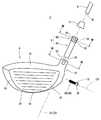
図1は本発明の一実施形態に係るゴルフクラブ2の一部を示す図であり、図2はゴルフクラブ2の分解図である。ゴルフクラブ2は、ヘッド4とシャフト6とを有する。シャフト6の一端部に、ヘッド4が取り付けられている。図示されないが、シャフト6の他端部にはグリップが取り付けられている。更に、図2が示すように、ゴルフクラブ2は、インナー部材8、ねじ部材10及びフェラル12を有する。インナー部材8及びねじ部材10は、ヘッド4とシャフト6とを固着するための部材である。フェラル12は、従来のゴルフクラブにおいて汎用されているものと同様である。フェラル12は無くてもよい。 FIG. 1 is a view showing a part of a
図3は、インナー部材8及びねじ部材10が取り付けられたヘッド4の斜視図である。ヘッド4は、ウッド型ゴルフクラブヘッドである。ヘッド4は、クラウン部14、ソール部16、サイド部18、フェース部20及びホーゼル部22を有する。ヘッド4は、中空である。フェース部20には、フェースライン24が設けられている。図3では、フェースライン24の記載が省略されている。なお、ヘッド4は、アイアン型ゴルフクラブヘッドでもよいし、他のあらゆるタイプのヘッドであってもよい。 FIG. 3 is a perspective view of the
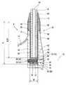
図4は、図1のIV−IV線に沿った断面図であり、図5は、図4のV−V線に沿った断面図であり、図6は、図4のVI−VI線に沿った断面図である。図7は、図2のVII−VII線に沿った断面図である。図7は、インナー部材8単体の断面図である。図8は、図7のVIII−VIII線に沿った断面図である。図8は、インナー部材8単体の断面図である。図9は、図2のIX−IX線に沿った断面図である。図5の断面と図8の断面とは、互いに直交する関係にある。
4 is a sectional view taken along line IV-IV in FIG. 1, FIG. 5 is a sectional view taken along line V-V in FIG. 4, and FIG. 6 is taken along line VI-VI in FIG. FIG. Figure 7 is a sectional view taken along line VII-VII ofFIG. FIG. 7 is a sectional view of the
ホーゼル部22は、ホーゼル孔26を有する。ホーゼル孔26は、上方に開口している。ホーゼル孔26は、その底面27まで真っ直ぐに延びている。ホーゼル孔26の内周面の断面形状は円形である。ホーゼル孔26は、シャフト軸線Z1方向に沿って下方に延びている。ヘッド4の内部には、ホーゼル孔26を形成するための孔形成部28が設けられている。 The
図2が示すように、ホーゼル部22は、その上端面30から下方に向かって延在する欠け部32を有する。欠け部32は、空間を構成する。図9が示すように、欠け部32は、ホーゼル部22の周方向において等間隔で設けられている。欠け部32は、ホーゼル部22の周方向において90度おきに設けられている。欠け部32は、4箇所設けられている。 As shown in FIG. 2, the
欠け部32は、シャフト軸線Z1に対して平行に延びている。欠け部32の幅は一定である。即ち、欠け部32の幅(周方向幅)は、シャフト軸線Z1方向のあらゆる位置において同一である。 The chipped
図4及び図5が示すように、シャフト6は管状とされている。シャフト6は円筒状とされている。シャフト6には、中空部34が存在する。この中空部34は、下方に開放されている。この中空部34は、シャフト6を貫通している。 As shown in FIGS. 4 and 5, the
ねじ部材10は、略円筒状である。図1及び図5が示すように、ねじ部材10は、頭部36と本体部38とを有する。頭部36の外径は、本体部38の外径よりも大きい。ねじ部材10の外周面には、ねじ部が設けられている。本体部38に、ねじ部40が設けられている。ねじ部40は、雄ねじである。図3が示すように、頭部36の端面には、溝42が設けられている。この溝42により、ねじ部材10の回転が容易とされている。溝42にマイナスドライバー等を係合させることにより、ねじ部材10のねじ込み及び取り外しが容易とされうる。 The
フェラル12は、汎用品である。フェラル12は、酢酸セルロース等よりなる。フェラル12は、挿入穴44を有している。挿入穴44にシャフト6が挿入されている。フェラル12の外周面は、テーパーを有する。フェラル12の下端面が、ホーゼル部の上端面30と当接している。フェラル12の下端面における外径は、ホーゼル部の上端面30の外径とほぼ等しい。 The
図7及び図8が示すように、インナー部材8は、シャフト挿入孔46と、底部48と、係合凸部50とを有する。更に、図8が示すように、インナー部材8は、係合孔52を有する。インナー部材8において、シャフト挿入孔46は上方に開口している。シャフト挿入孔46は、インナー部材8の上端面から底部48にまで延在している。インナー部材8は、全体として一体である。一体とされたインナー部材8は、高強度である。 As shown in FIGS. 7 and 8, the
図5及び図6が示すように、シャフト挿入孔46には、シャフト6が挿入されている。シャフト挿入孔46とシャフト6とは、接着により固着されている。換言すれば、シャフト挿入孔46の内周面とシャフト6の外周面とは接着されている。接着には、接着剤が用いられている。シャフト挿入孔46とシャフト6とは、嵌合により固着されていてもよい。嵌合と接着剤による接着とが併用されてもよい。 As shown in FIGS. 5 and 6, the
係合孔52は、インナー部材8を貫通している。係合孔52は、インナー部材8の底部48を貫通している。シャフト挿入孔46の軸線Z2(図8参照)と、係合孔52の軸線Z3(図5参照)とは、互いに直交している。なお、シャフト挿入孔46の軸線Z2は、シャフト軸線Z1と共通である。 The
本実施形態では、係合孔52は、円柱状である底部48を貫通している。軸線Z3に沿った係合孔52の長さは、インナー部材8の円筒部分の外径と同じである。なお、係合孔52が、シャフト挿入孔46の軸方向外側に存在する側壁54を貫通してなる孔であってもよい。ただしこの場合、インナー部材8とねじ部材10との係合面積が小さくなりやすい。またこの場合、インナー部材8の強度が低下しやすい。ねじ部材10による係合を確実とする観点から、係合孔52は、シャフト挿入孔46よりも下方に設けられた底部48を貫通してなるのが好ましい。本実施形態において、この底部48は、係合孔52を除き中実である。中実とされることにより、係合孔52の周囲におけるインナー部材8の厚みが大きくなり、インナー部材8の強度が一層向上しうる。 In the present embodiment, the
図5が示すように、係合孔52には、ねじ部56が設けられている。ねじ部56は、雌ねじである。係合孔52のねじ部56と、ねじ部材10のねじ部40とがねじ結合している。このねじ結合により、インナー部材8とねじ部材10との係合が確実とされている。 As shown in FIG. 5, the
なお、図1が示すように、ゴルフクラブ2において、インナー部材8は外部から視認されない。インナー部材8はヘッド4により隠蔽されている。一方、図3が示すように、ねじ部材10の頭部36の端面は、露出している。 In addition, as FIG. 1 shows, in the
インナー部材8の少なくとも一部は、ホーゼル孔26に挿入されている。本実施形態では、インナー部材8の全部がホーゼル孔26に挿入されている。ホーゼル孔26に挿入されることにより、インナー部材8は、ホーゼル孔26により保持されている。インナー部材8とホーゼル孔26とは接着されていない。 At least a part of the
シャフト6の先端部は、シャフト挿入孔46に挿入されているとともに、ホーゼル孔26の内部に位置している。換言すれば、シャフト6は、シャフト挿入孔46に挿入されつつホーゼル孔26の内部に配置された部分を有する。この構成により、シャフト6は、シャフト挿入孔46により保持されるとともに、ホーゼル孔26によっても支持されている。この構成により、シャフト6の先端部に作用する応力がホーゼル孔26によって受け止められる。よって、シャフト挿入孔46及びシャフト6の変形が抑制される。この結果、シャフト6とシャフト挿入孔46との固着が維持されやすくなり、且つインナー部材8がホーゼル孔26から抜けにくくなる。 The tip of the
前述したように、インナー部材8は、係合凸部50を有する。図8が示すように、係合凸部50は、インナー部材8の上端部に設けられている。係合凸部50は、インナー部材8の外面に設けられている。図7が示すように、係合凸部50は、半径方向外側に突出している。図4が示すように、係合凸部50は、欠け部32に配置されている。係合凸部50は、欠け部32に挿入されている。係合凸部50と欠け部32とは、係合している。係合凸部50の形状は、欠け部32の形状と対応している。係合凸部50の配置は、欠け部32の配置と対応している。欠け部32と同様に、係合凸部50は、周方向において等間隔おきに配置されている。係合凸部50と欠け部32との係合により、ヘッド4のホーゼル部22とインナー部材8との相対回転(周方向における相対回転)が規制されている。ホーゼル部22とインナー部材8との相対回転を抑制する観点から、係合凸部50は欠け部32に嵌合しているのがよい。ホーゼル部22とインナー部材8との相対回転を抑制する観点から、係合凸部50と欠け部32とは、周方向において隙間がないように嵌合しているのが好ましい。係合凸部50は、少なくとも1個存在すればよい。欠け部32は、少なくとも1個存在すればよい。 As described above, the
欠け部32及び係合凸部50は、ホーゼル孔26に対するインナー部材8の挿入長さS(図5参照)を規制するストッパーの役割をも果たしている。即ち、係合凸部50の下端58と欠け部32の下端60との係合により(図5参照)、インナー部材8の挿入長さSが規制されている。 The chipped
図5が示すように、シャフト6の下端の端面62は、インナー部材8の底部48に当接している。この当接により、シャフト挿入孔46に対するシャフト6の挿入長さが最大限となり、インナー部材8とシャフト6との当接面積が大きくされうる。これにより、シャフト6とインナー部材8との固着がより一層確実とされている。端面62は、底部48に当接していなくてもよい。 As shown in FIG. 5, the
図2及び図8が示すように、インナー部材8は、円周面部64と係合部66とを有する。円周面部64は、外面が円周面である部分である。係合部66は、外面に係合凸部50が配置された部分である。円周面部64と係合部66との境界は、係合凸部50の下端58である。係合部66は、円周面部64の上側に位置している。 As shown in FIGS. 2 and 8, the
図5が示すように、ヘッド4は、ヘッド孔70を有している。ヘッド孔70は、ホーゼル孔26よりもヘッド外面側に設けられた外側ヘッド孔72と、ホーゼル孔26よりもヘッド内部側に設けられた内側ヘッド孔74とを有する。外側ヘッド孔72は、ヘッド4の外面からホーゼル孔26にまで至っている。内側ヘッド孔74は、ホーゼル孔26の内周面からヘッド4の中空部にまで至っている。内側ヘッド孔74は、ヘッド4の孔形成部28を貫通している。外側ヘッド孔72と内側ヘッド孔74とは同軸で配置されている。換言すれば、外側ヘッド孔72の中心軸と内側ヘッド孔74の中心軸とは共通である。ヘッド孔70は、ホーゼル孔26により、外側ヘッド孔72と内側ヘッド孔74とに分断されている。 As shown in FIG. 5, the
ヘッド孔70とインナー部材8の係合孔52とは、互いに連続した単一の孔を形成している。係合孔52とヘッド孔70とが連続してなる連続孔76が形成されている。係合孔52の軸線とヘッド孔70の軸線とは、共通である。外側ヘッド孔72と係合孔52と内側ヘッド孔74とにより、連続孔76が形成されている。この連続孔76に、ねじ部材10が挿入されている。ねじ部材10は、外側ヘッド孔72、係合孔52及び内側ヘッド孔74に挿入されている。連続孔76は外部に開口している。連続孔76はヘッド4のサイド部18に開口している。この開口からねじ部材10をねじ込むことができる。 The
係合孔52の内周面には、ねじ部が形成されている。この係合孔52のねじ部は、雌ねじである。ヘッド孔70の内周面には、ねじ部が形成されていない。即ち、外側ヘッド孔72の内周面にはねじ部が形成されておらず、且つ、内側ヘッド孔74の内周面にはねじ部が形成されていない。 A threaded portion is formed on the inner peripheral surface of the
ねじ部材10は、係合孔52とねじ結合している。即ち、係合孔52の雌ねじとねじ部材10のねじ部40(雄ねじ)とがねじ結合している。ヘッド孔70とねじ部材10とはねじ結合していない。つまり、外側ヘッド孔72とねじ部材10とはねじ結合しておらず、且つ、内側ヘッド孔74とねじ部材10とはねじ結合していない。 The
このように、連続孔76の少なくとも一部とねじ部材10とはねじ結合している。本実施形態では、係合孔52とねじ部材10とがねじ結合している。このねじ結合により、インナー部材8とねじ部材10とが強固に係合している。また、ねじ部材10は、ヘッド孔70とも係合している。即ちねじ部材10は、外側ヘッド孔72及び内側ヘッド孔74に挿入されることにより、ヘッド孔70と係合している。よって、ねじ部材10により、インナー部材8とヘッド4とが確実に係合されている。この係合により、インナー部材8がホーゼル孔26から抜けることが防止されている。 Thus, at least a part of the
図5が示す断面図において、ヘッドの外面(サイド部18の外面)とホーゼル孔26との間には空間がない。換言すれば、ヘッドの外面とホーゼル孔26との間においてヘッドは中実である。ヘッドの外面とホーゼル孔26との間に、ヘッド4の中空部は存在しない。 In the cross-sectional view shown in FIG. 5, there is no space between the outer surface of the head (the outer surface of the side portion 18) and the
上記ねじ結合の締結により軸力が発生しうる。この軸力は、ねじ部材の軸線方向に作用する力である。この軸力によりホーゼル部22が変形すると、ホーゼル孔26の軸線方向が変動しうる。ホーゼル孔26の軸線方向が変動すると、シャフト軸線Z1の方向が変動し、ヘッドのライ角やリアルロフト角が変動するので好ましくない。また、ホーゼル部22の変形によりホーゼル孔26が曲がった場合、インナー部材8をホーゼル孔26に挿入することが困難となりうる。ねじ部材の軸力によりホーゼル部の変形を抑制する観点から、少なくともヘッド孔70の開口部よりも上側の領域において、ヘッド外面とホーゼル孔26との間には空間がないのが好ましい。換言すれば、少なくともヘッド孔70の開口部よりも上側の領域に関し、ヘッド外面とホーゼル孔26との間においてヘッド4は中実であるのが好ましい。より好ましくは、ホーゼル孔26全体の領域において、ヘッド外面とホーゼル孔26との間には空間がないのが好ましい。 An axial force can be generated by fastening the screw connection. This axial force is a force acting in the axial direction of the screw member. When the
ねじ部材10と連続孔76との係合(第一の係合)は、ヘッド4のホーゼル部22とインナー部材8との相対回転を規制している。前述したように、この相対回転の規制は、係合凸部50と欠け部32との係合(第二の係合)によっても達成されている。この構成により、相対回転に係る応力が第一の係合と第二の係合とに分散されるため、応力集中が緩和されている。第一の係合と第二の係合とが併用されることにより、上記相対回転が確実に防止されている。 Engagement (first engagement) between the
ヘッド4は、連続孔76に対するねじ部材10のねじ込み深さを規制する規制機構を有している。この規制機構は、ねじ部材10の段差面78と、この段差面78に当接する受け面80とから構成されている。ねじ部材10の段差面78は、頭部36と本体部38との境界に位置している。段差面78の存在は、頭部36の外径が本体部38の外径よりも大きくされていることに起因している。外側ヘッド孔72の形状は、このねじ部材10の形状に対応している。段差面78と受け面80との当接により、ねじ部材10のねじ込み深さが規制されている。この規制機構により、ねじ部材10を強固に締め込むことができ、ねじ部材10が緩みにくくなり、ねじ部材10の外れが抑制される。よって、この規制機構により、インナー部材8とホーゼル孔26との結合がより一層確実とされうる。 The
前述したように、ホーゼル部22の欠け部32と、インナー部材8の係合凸部50とは係合している。この係合により、係合孔52がヘッド孔70と連続するように位置決めされている。図7が示すように、本実施形態では、係合凸部50は周方向90度おきに均等に配置されている。よって、係合凸部50と欠け部32とが係合した状態において、インナー部材8は、周方向において4通りに配置されうる。このうち適切な2通りが選択されることにより、連続孔76が形成されうる。更に、より適切な1通りが選択されることにより、ねじ部材10のねじ込みが可能な連続孔76が形成される。このように、欠け部32と係合凸部50との係合により、係合孔52とヘッド孔70とが連続するように位置決めされる。欠け部32と係合凸部50との係合により、位置決め調整の手間が省略されうる。 As described above, the chipped
上記実施形態では、ホーゼル孔26に対するインナー部材8の挿入長さSを規制する挿入長規制機構を有している。前述の通り、本実施形態では、この挿入長規制機構は、係合凸部50の下端58と欠け部32の下端60との係合により構成されている。他の挿入長規制機構として、例えば、ホーゼル孔26の底部に設けられインナー部材8の下端面と当接するストッパーが挙げられる。 In the said embodiment, it has the insertion length control mechanism which controls the insertion length S of the
このような挿入長規制機構により、ホーゼル部22に対するインナー部材8の固定がより一層確実とされうる。即ち、インナー部材8は、ねじ部材10によりヘッド4と係合し、更にこの挿入長規制機構によりヘッド4と係合している。よって、ホーゼル孔26に対するインナー部材8の固定がより一層確実とされている。 By such an insertion length restriction mechanism, the
前述したように、インナー部材8とシャフト6とは固着されている。よって、インナー部材8がヘッド4に対して固定されれば、シャフト6がヘッド4に対して固定される。また、ねじ部材10を取り外してねじ止めを解除することにより、ヘッド4とシャフト6との分離が可能となる。即ち、シャフト6はヘッド4に対して着脱可能である。 As described above, the
ゴルフクラブ2の組立手順として、次の手順1が例示される。
The following procedure1 is illustrated as an assembling procedure of the
[組立手順1]は、以下の工程(1)から(4)である。
(1)フェラル12の挿入穴44にシャフト6を圧入する。
(2)インナー部材8のシャフト挿入孔46にシャフト6の先端部を差し込み、この先端部とインナー部材8とを接着剤等により接合する。
(3)インナー部材8をホーゼル孔26に差し込む。
(4)ねじ部材10をヘッド孔70に挿入し、ねじ止めする。[Assembly Procedure 1] includes the following steps (1) to (4).
(1) The
(2) The tip end portion of the
(3) Insert the
(4) The
なお、上記工程(1)は、一般に「フェラル打ち込み」とも称される。フェラル打ち込みは、通常のゴルフクラブの組み立てにおいても実施される工程である。工程(1)により、フェラル12がシャフト6上の所定位置に固定される。この所定位置は、ゴルフクラブ2における位置と同じである。 The step (1) is also generally referred to as “ferrule driving”. Ferrule driving is a process performed in the assembly of a normal golf club. By the step (1), the
上記手順1により組み立てられた後は、シャフト6の着脱は容易である。即ち、ねじ機構の締め付け及び解除により、シャフト6がヘッド4に対して着脱されうる。組み立てられる前の部品としてシャフト6を販売する場合、上記組立手順1において工程(2)まで終了してなる部材が販売されてもよい。 After the assembly by the procedure 1, the
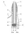
図10は、他の実施形態にかかるヘッド82の断面図である。前述したヘッド4とヘッド82とで相違するのは、連続孔及びねじ部材の構成である。連続孔及びねじ部材を除き、ヘッド82はヘッド4と同様の構成である。 FIG. 10 is a cross-sectional view of a
図10が示すように、ヘッド82は、ヘッド孔84を有している。ヘッド82は、ホーゼル孔26よりもヘッド外面側に設けられた外側ヘッド孔86と、ホーゼル孔26よりもヘッド内部側に設けられた内側ヘッド孔88とを有する。外側ヘッド孔86は、ヘッド82の外面からホーゼル孔26にまで至っている。内側ヘッド孔88は、ホーゼル孔26の内周面からヘッド82の中空部にまで至っていない。内側ヘッド孔88は、ヘッド82の孔形成部28を貫通していない。内側ヘッド孔88は、有底である。内側ヘッド孔88は、底面90を有する。外側ヘッド孔72と内側ヘッド孔88とは同軸で配置されている。換言すれば、外側ヘッド孔86の中心軸と内側ヘッド孔88の中心軸とは共通である。ヘッド孔84は、ホーゼル孔26により、外側ヘッド孔86と内側ヘッド孔88とに分断されている。 As shown in FIG. 10, the
ヘッド孔84とインナー部材92の係合孔94とは、互いに連続した単一の孔を形成している。係合孔94とヘッド孔84とが連続してなる連続孔96が形成されている。外側ヘッド孔86と係合孔94と内側ヘッド孔88とにより、連続孔96が形成されている。この連続孔96に、ねじ部材98が挿入されている。ねじ部材98は、外側ヘッド孔86、係合孔94及び内側ヘッド孔88に挿入されている。連続孔96は外部に開口している。連続孔96はヘッド82のサイド部18に開口している。この開口からねじ部材98をねじ込むことができる。 The
係合孔94の内周面には、ねじ部が形成されている。この係合孔94のねじ部は、雌ねじである。ヘッド孔84の内周面には、ねじ部が形成されていない。即ち、外側ヘッド孔86の内周面にはねじ部が形成されておらず、且つ、内側ヘッド孔88の内周面にはねじ部が形成されていない。 A thread portion is formed on the inner peripheral surface of the
ねじ部材98は、頭部を有していない。ねじ部材98の外径は、その全長に渡って略同一である。ねじ部材98は、係合孔94とねじ結合している。即ち、係合孔94のねじ部(雌ねじ)とねじ部材98のねじ部(雄ねじ)とがねじ結合している。ヘッド孔84とねじ部材98とはねじ結合していない。つまり、外側ヘッド孔86とねじ部材98とはねじ結合しておらず、且つ、内側ヘッド孔88とねじ部材98とはねじ結合していない。 The
このように、連続孔96の少なくとも一部とねじ部材98とはねじ結合している。本実施形態では、係合孔94とねじ部材98とがねじ結合している。このねじ結合により、インナー部材92とねじ部材98とが強固に係合している。また、ねじ部材98は、ヘッド孔84とも係合している。即ちねじ部材98は、外側ヘッド孔86及び内側ヘッド孔88に挿入されることにより、ヘッド孔84と係合している。よって、ねじ部材98により、インナー部材92とヘッド82とが確実に係合されている。この係合により、インナー部材92がホーゼル孔26から抜けることが防止されている。 Thus, at least a part of the
ヘッド82は、連続孔96に対するねじ部材98のねじ込み深さを規制する規制機構を有している。この規制機構は、ねじ部材98の端面100と、この端面100に当接する
底面90とから構成されている。ねじ部材98の端面100は、ねじ部材98のねじ込み進行方向側の端面である。底面90と端面100との当接により、ねじ部材98のねじ込み深さが規制されている。この規制機構により、ねじ部材98を強固に締め込むことができ、ねじ部材98が緩みにくくなり、ねじ部材98の外れが抑制される。よって、この規制機構により、インナー部材92とホーゼル孔26との結合がより一層確実とされうる。なお、このヘッド82においても、欠け部と係合凸部との係合により、係合孔94とヘッド孔84とが連続するように位置決めされている。The
図11は、他の実施形態に係るヘッド102の断面図である。前述したヘッド4とヘッド102とで相違するのは、連続孔及びねじ部材の構成である。連続孔及びねじ部材を除き、ヘッド102の構成はヘッド4の構成と同じである。 FIG. 11 is a cross-sectional view of a
図11が示すように、ヘッド102は、ヘッド孔104を有している。ヘッド102は、ホーゼル孔26よりもヘッド外面側に設けられた外側ヘッド孔106を有する。ヘッド孔104は、外側ヘッド孔106のみから構成されている。ヘッド孔104は、ホーゼル孔26よりもヘッド内部側に設けられた内側ヘッド孔を有していない。ヘッド孔104は、ホーゼル孔26よりもヘッド外面側にのみ設けられている。外側ヘッド孔106は、ヘッド102の外面からホーゼル孔26にまで至っている。 As shown in FIG. 11, the
ヘッド孔104とインナー部材108の係合孔110とは、互いに連続した単一の孔を形成している。係合孔110とヘッド孔104とが連続してなる連続孔112が形成されている。ヘッド孔104と係合孔110とにより、連続孔112が形成されている。この連続孔112に、ねじ部材114が挿入されている。ねじ部材114は、ヘッド孔104(外側ヘッド孔106)及び係合孔110に挿入されている。連続孔112は外部に開口している。連続孔112はヘッド102のサイド部18に開口している。この開口からねじ部材114をねじ込むことができる。 The
係合孔110の内周面には、ねじ部が形成されている。この係合孔110のねじ部は、雌ねじである。ヘッド孔104の内周面には、ねじ部が形成されていない。 A threaded portion is formed on the inner peripheral surface of the
ねじ部材114は、頭部を有していない。ねじ部材114の外径は、その全長に渡って略同一である。ねじ部材114は、係合孔110とねじ結合している。即ち、係合孔110のねじ部(雌ねじ)とねじ部材114のねじ部(雄ねじ)とがねじ結合している。ヘッド孔104とねじ部材114とはねじ結合していない。 The
このように、連続孔112の少なくとも一部とねじ部材114とはねじ結合している。本実施形態では、係合孔110とねじ部材114とがねじ結合している。このねじ結合により、インナー部材108とねじ部材114とが強固に係合している。また、ねじ部材114は、ヘッド孔104とも係合している。ヘッド孔104に挿入されることにより、ねじ部材114はヘッド孔104と係合している。よって、ねじ部材114により、インナー部材108とヘッド102とが確実に係合されている。この係合により、インナー部材108がホーゼル孔26から抜けることが防止されている。 Thus, at least a part of the
ヘッド102は、連続孔112に対するねじ部材114のねじ込み深さを規制する規制機構を有している。この規制機構は、ねじ部材114の端面116と、この端面116に当接するホーゼル孔26の内周面とから構成されている。端面116は、ねじ部材114のねじ込み進行方向側の端面である。ホーゼル孔26の内周面と端面116との当接により、ねじ部材114のねじ込み深さが規制されている。この規制機構により、ねじ部材114を強固に締め込むことができる。よって、ねじ部材114が緩みにくくなり、ねじ部材114の外れが抑制される。よって、この規制機構により、インナー部材108とホーゼル孔26との結合がより一層確実とされうる。なお、このヘッド102においても、欠け部と係合凸部との係合により、係合孔110とヘッド孔104とが連続するように位置決めされている。 The
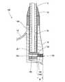
図12は、他の実施形態に係るヘッド118の断面図である。図12が示すように、ヘッド118は、ヘッド孔120を有している。ヘッド孔120は、ホーゼル孔26よりもヘッド外面側に設けられた外側ヘッド孔122と、ホーゼル孔26よりもヘッド内部側に設けられた内側ヘッド孔124とを有する。外側ヘッド孔122は、ヘッド118の外面からホーゼル孔26にまで至っている。内側ヘッド孔124は、ホーゼル孔26の内周面からヘッド118の中空部にまで至っている。内側ヘッド孔124は、ヘッド118の孔形成部28を貫通している。外側ヘッド孔122と内側ヘッド孔124とは同軸で配置されている。換言すれば、外側ヘッド孔122の中心軸と内側ヘッド孔124の中心軸とは共通である。ヘッド孔120は、ホーゼル孔26により、外側ヘッド孔122と内側ヘッド孔124とに分断されている。 FIG. 12 is a cross-sectional view of a
ヘッド孔120とインナー部材126の係合孔128とは、互いに連続した単一の孔を形成している。係合孔128とヘッド孔120とが連続してなる連続孔130が形成されている。外側ヘッド孔122と係合孔128と内側ヘッド孔124とにより、連続孔130が形成されている。この連続孔130に、ねじ部材132が挿入されている。ねじ部材132は、外側ヘッド孔122、係合孔128及び内側ヘッド孔124に挿入されている。連続孔130は外部に開口している。連続孔130はヘッド118のサイド部18に開口している。この開口からねじ部材132をねじ込むことができる。 The
本実施形態では、インナー部材126とねじ部材132とがねじ結合していない。係合孔128の内周面には、ねじ部が形成されていない。一方、ヘッド孔120の内周面の少なくとも一部に、ねじ部が形成されている。本実施形態では、内側ヘッド孔124の内周面にねじ部が形成されている。外側ヘッド孔122の内周面にはねじ部が形成されていない。 In the present embodiment, the
ねじ部材132は、内側ヘッド孔124とねじ結合している。即ち、内側ヘッド孔124のねじ部(雌ねじ)とねじ部材132のねじ部(雄ねじ)とがねじ結合している。本実施形態では、ヘッド孔120とねじ部材132とがねじ結合している。 The
このように、連続孔130の少なくとも一部とねじ部材132とがねじ結合している。本実施形態では、内側ヘッド孔124とねじ部材132とがねじ結合している。このねじ結合により、ヘッド孔120とねじ部材132とが強固に係合している。また、ねじ部材132は、インナー部材126とも係合している。即ちねじ部材132は、係合孔128に挿入されることにより、インナー部材126と係合している。よって、ねじ部材132により、インナー部材126とヘッド118とが確実に係合されている。この係合により、インナー部材126がホーゼル孔26から抜けることが防止されている。 Thus, at least a part of the
ヘッド118は、連続孔130に対するねじ部材132のねじ込み深さを規制する規制機構を有している。この規制機構は、ねじ部材132の段差面134と、この段差面134に当接する受け面136とから構成されている。ねじ部材132は、頭部138と本体部140とを有している。ねじ部材132の段差面134は、頭部138と本体部140との境界に位置している。段差面134の存在は、頭部138の外径が本体部140の外径よりも大きくされていることに起因している。外側ヘッド孔122の形状は、このねじ部材132の形状に対応している。段差面134と受け面136との当接により、ねじ部材132のねじ込み深さが規制されている。この規制機構により、ねじ部材132を強固に締め込むことができる。よって、ねじ部材132が緩みにくくなり、ねじ部材132の外れが抑制される。この規制機構により、インナー部材126とホーゼル孔26との結合がより一層確実とされうる。なお、このヘッド118においても、欠け部と係合凸部との係合により、係合孔128とヘッド孔120とが連続するように位置決めされている。 The
図13は、他の実施形態に係るヘッド142の断面図である。前述したヘッド4とヘッド142とで相違するのは、連続孔及びねじ部材の構成である。連続孔及びねじ部材を除き、ヘッド142の構成はヘッド4の構成と同じである。 FIG. 13 is a cross-sectional view of a
図13が示すように、ヘッド142は、ヘッド孔144を有している。ヘッド142は、ホーゼル孔26よりもヘッド外面側に設けられた外側ヘッド孔146を有する。ヘッド孔144は、外側ヘッド孔146のみから構成されている。ヘッド孔144は、ホーゼル孔26よりもヘッド内部側に位置する内側ヘッド孔を有していない。ヘッド孔144は、ホーゼル孔26よりもヘッド外面側にのみ設けられている。外側ヘッド孔146は、ヘッド142の外面からホーゼル孔26にまで至っている。 As shown in FIG. 13, the
ヘッド孔144とインナー部材148の係合孔150とは、互いに連続した単一の孔を形成している。係合孔150とヘッド孔144とが連続してなる連続孔152が形成されている。ヘッド孔144と係合孔150とにより、連続孔152が形成されている。この連続孔152に、ねじ部材154が挿入されている。ねじ部材154は、ヘッド孔144(外側ヘッド孔146)及び係合孔150に挿入されている。連続孔152は外部に開口している。連続孔152はヘッド142のサイド部18に開口している。この開口からねじ部材154をねじ込むことができる。 The
係合孔150の内周面には、ねじ部が形成されていない。一方、ヘッド孔144の内周面には、ねじ部が形成されている。このねじ部は、雌ねじである。 A threaded portion is not formed on the inner peripheral surface of the
ねじ部材154は、頭部を有していない。ねじ部材154は、ヘッド孔144とねじ結合している。即ち、ヘッド孔144のねじ部(雌ねじ)とねじ部材154のねじ部(雄ねじ)とがねじ結合している。係合孔150とねじ部材154とはねじ結合していない。 The
このように、連続孔152の少なくとも一部とねじ部材154とはねじ結合している。本実施形態では、ヘッド孔144とねじ部材154とがねじ結合している。このねじ結合により、ヘッド孔144とねじ部材154とが強固に係合している。また、ねじ部材154は、インナー部材148とも係合している。ねじ部材154が係合孔150に挿入されることにより、ねじ部材154はインナー部材148と係合している。よって、ねじ部材154により、インナー部材148とヘッド142とが確実に結合されている。この結合により、インナー部材148がホーゼル孔26から抜けることが防止されている。 Thus, at least a part of the
ヘッド142は、連続孔152に対するねじ部材154のねじ込み深さを規制する規制機構を有している。この規制機構は、ねじ部材154の端面158と、この端面158に当接するホーゼル孔26の内周面とから構成されている。端面158は、ねじ部材154のねじ込み進行方向側の端面である。ホーゼル孔26の内周面と端面158との当接により、ねじ部材154のねじ込み深さが規制されている。この規制機構により、ねじ部材154を強固に締め込むことができる。よって、ねじ部材154が緩みにくくなり、ねじ部材154の外れが抑制される。この規制機構により、インナー部材148とホーゼル孔26との結合がより一層確実とされうる。なお、このヘッド142においても、欠け部と係合凸部との係合により、係合孔150とヘッド孔144とが連続するように位置決めされている。 The
ヘッドの材質は、限定されない。ヘッドの材質として、チタン、チタン合金、CFRP(炭素繊維強化プラスチック)、ステンレス鋼、マルエージング鋼、マグネシウム合金、アルミニウム合金、鉄等が例示される。複数の材質を組み合わせたヘッドでもよい。鋳造により作製されたヘッド本体と、鍛造又はプレスにより作製されたフェース部とが接合されたヘッドであってもよい。 The material of the head is not limited. Examples of the material of the head include titanium, titanium alloy, CFRP (carbon fiber reinforced plastic), stainless steel, maraging steel, magnesium alloy, aluminum alloy, and iron. A head in which a plurality of materials are combined may be used. A head in which a head body manufactured by casting and a face portion manufactured by forging or pressing are joined may be used.
ヘッドの構造は、限定されない。ヘッドは、全体として一体成形されていてもよいし、複数の部材を接合してなるものであってもよい。ヘッドの製造方法は限定されない。ヘットの製造方法として、ロストワックス精密鋳造等の鋳造、鍛造等が例示される。なお、ヘッド孔は、ヘッド成形と同時に成形されてもよいし、ヘッドの成形後に機械加工等により形成されてもよい。 The structure of the head is not limited. The head may be integrally formed as a whole, or may be formed by joining a plurality of members. The method for manufacturing the head is not limited. Examples of the method for producing the head include casting such as lost wax precision casting, forging, and the like. The head hole may be formed simultaneously with the head formation, or may be formed by machining or the like after the head formation.
シャフトの材質は、限定されない。シャフトの材質として、CFRP(炭素繊維強化プラスチック)や金属が例示される。いわゆるカーボンシャフトやスチールシャフトが好適に用いられうる。また、シャフトの構造は、限定されない。 The material of the shaft is not limited. Examples of the material of the shaft include CFRP (carbon fiber reinforced plastic) and metal. A so-called carbon shaft or steel shaft can be suitably used. Further, the structure of the shaft is not limited.
インナー部材の材質は、限定されない。インナー部材の材質として、ステンレス鋼、アルミニウム、アルミニウム合金、チタン、チタン合金、マグネシウム、マグネシウム合金、CFRP(炭素繊維強化プラスチック)、樹脂等があげられる。特に係合孔付近の強度を高める観点から、インナー部材は高強度であるのが好ましい。これらの観点から、インナー部材の材質としては、ステンレス鋼、チタン、チタン合金等が好ましい。 The material of the inner member is not limited. Examples of the material of the inner member include stainless steel, aluminum, aluminum alloy, titanium, titanium alloy, magnesium, magnesium alloy, CFRP (carbon fiber reinforced plastic), resin, and the like. In particular, from the viewpoint of increasing the strength in the vicinity of the engagement hole, the inner member is preferably high in strength. From these viewpoints, the material of the inner member is preferably stainless steel, titanium, titanium alloy, or the like.
ねじ部材の材質は、限定されない。ねじ部材の材質として、ステンレス鋼、アルミニウム、アルミニウム合金、チタン、チタン合金、マグネシウム、マグネシウム合金、CFRP(炭素繊維強化プラスチック)、樹脂等があげられる。打球時における耐力を高める観点から、ねじ部材は高強度であるのが好ましい。これらの観点から、ねじ部材の材質としては、ステンレス鋼、チタン、チタン合金等が好ましい。 The material of the screw member is not limited. Examples of the material of the screw member include stainless steel, aluminum, aluminum alloy, titanium, titanium alloy, magnesium, magnesium alloy, CFRP (carbon fiber reinforced plastic), resin, and the like. From the viewpoint of increasing the yield strength at the time of hitting, the screw member preferably has high strength. From these viewpoints, the material of the screw member is preferably stainless steel, titanium, titanium alloy, or the like.
図8において両矢印Aで示されるのは、シャフト挿入孔の深さである。インナー部材とシャフトとの接着強度を高める観点から、深さAは、20mm以上が好ましく、23mm以上がより好ましく、28mm以上が更に好ましい。インナー部材が長い場合、ホーゼル孔26が深くされる傾向となり、ホーゼル部の重量が増加しやすい。ホーゼル部の重量を抑え、重心距離が過度に短くなったり重心位置が過度に高くなったりすることを抑制する観点から、深さAは、40mm以下が好ましく、38mm以下がより好ましく、35mm以下が更に好ましい。 In FIG. 8, a double arrow A indicates the depth of the shaft insertion hole. From the viewpoint of increasing the adhesive strength between the inner member and the shaft, the depth A is preferably 20 mm or more, more preferably 23 mm or more, and even more preferably 28 mm or more. When the inner member is long, the
図8において両矢印Bで示されるのは、インナー部材における円周面部の外径である。外径Bが過度に小さい場合、シャフト挿入孔の内径が十分に確保できず、シャフトとインナー部材との接着強度が低くなりやすい。この観点から、外径Bは、7.0mm以上が好ましく、8.0mm以上がより好ましく、8.5mm以上が更に好ましい。インナー部材8が太い場合、ホーゼル孔の内径も大きくなる傾向となり、ホーゼル部の重量が増加しやすい。ホーゼル部の重量を抑え、重心距離が過度に短くなったり重心位置が過度に高くなったりすることを抑制する観点から、外径Bは、12.0mm以下が好ましく、11.0mm以下がより好ましく、10.0mm以下が更に好ましい。 In FIG. 8, what is indicated by a double arrow B is the outer diameter of the circumferential surface portion of the inner member. When the outer diameter B is excessively small, the inner diameter of the shaft insertion hole cannot be secured sufficiently, and the adhesive strength between the shaft and the inner member tends to be low. In this respect, the outer diameter B is preferably equal to or greater than 7.0 mm, more preferably equal to or greater than 8.0 mm, and still more preferably equal to or greater than 8.5 mm. When the
ホーゼル孔によるインナー部材の支持を確実とする観点から、円周面部の外径Bは、ホーゼル孔の孔径αと略同一であるのが好ましい。具体的には、外径B(mm)と孔径α(mm)とは、次の関係式を満たすのが好ましい。
[α−0.20]≦B≦αFrom the viewpoint of ensuring the support of the inner member by the hosel hole, the outer diameter B of the circumferential surface portion is preferably substantially the same as the hole diameter α of the hosel hole. Specifically, it is preferable that the outer diameter B (mm) and the hole diameter α (mm) satisfy the following relational expression.
[Α−0.20] ≦ B ≦ α
図8において両矢印Cで示されるのは、係合凸部の軸方向長さである。打球時におけるインナー部材とホーゼル部との相対回転を抑制する観点から、長さCは、5.0mm以上が好ましく、8.0mm以上がより好ましく、10.0mm以上が更に好ましい。長さCが長すぎると、インナー部材及びホーゼル孔が長くなる傾向となり、インナー部材及びホーゼル部の重量が増加しやすい。この重量増加により、重心距離が過度に短くなったり重心位置が過度に高くなったりしやすい。重心距離が過度に短くなったり重心位置が過度に高くなったりすることを抑制する観点から、長さCは、20.0mm以下が好ましく、17.0mm以下がより好ましく、15.0mm以下が更に好ましい。 In FIG. 8, a double arrow C indicates the axial length of the engaging convex portion. From the viewpoint of suppressing the relative rotation between the inner member and the hosel portion at the time of hitting, the length C is preferably 5.0 mm or more, more preferably 8.0 mm or more, and further preferably 10.0 mm or more. When the length C is too long, the inner member and the hosel hole tend to be long, and the weight of the inner member and the hosel part tends to increase. This weight increase tends to make the center of gravity distance too short or the center of gravity position too high. From the viewpoint of suppressing the center of gravity distance from becoming excessively short or the position of the center of gravity from excessively increasing, the length C is preferably 20.0 mm or less, more preferably 17.0 mm or less, and further preferably 15.0 mm or less. preferable.
図7及び図8において両矢印Dで示されるのは、係合凸部の突出長さである。この突出長さDは、半径方向において測定される。係合凸部の強度を高め、インナー部材とホーゼル部との相対回転を抑制する観点から、長さDは、1.0mm以上が好ましく、1.2mm以上がより好ましく、1.5mm以上が更に好ましい。インナー部材の重量が過度に増加すると、インナー部材を含めたヘッド部分の重心位置が、過度に高くなったりヒール寄りになったりしやすい。インナー部材の重量を抑える観点から、長さDは、3.0mm以下が好ましく、2.7mm以下がより好ましく、2.5mm以下が更に好ましい。 In FIGS. 7 and 8, what is indicated by a double-headed arrow D is the protruding length of the engaging convex portion. This protrusion length D is measured in the radial direction. From the viewpoint of increasing the strength of the engaging convex portion and suppressing the relative rotation between the inner member and the hosel portion, the length D is preferably 1.0 mm or more, more preferably 1.2 mm or more, and further preferably 1.5 mm or more. preferable. When the weight of the inner member is excessively increased, the position of the center of gravity of the head portion including the inner member tends to be excessively high or close to the heel. From the viewpoint of suppressing the weight of the inner member, the length D is preferably 3.0 mm or less, more preferably 2.7 mm or less, and even more preferably 2.5 mm or less.
図8において両矢印Eで示されるのは、シャフト挿入孔の内径である。シャフト外径が過度に小さくなることと抑制しシャフトの強度を高める観点から、内径Eは、7.0mm以上が好ましく、7.5mm以上がより好ましく、8.0mm以上が更に好ましい。シャフト外径が過度に小さくなることを抑制し、シャフト先端部が過度に硬くなることを抑制する観点から、内径Eは、11.0mm以下が好ましく、10.5mm以下がより好ましく、10.0mm以下が更に好ましい。 A double arrow E in FIG. 8 indicates the inner diameter of the shaft insertion hole. From the viewpoint of suppressing the shaft outer diameter from becoming excessively small and increasing the strength of the shaft, the inner diameter E is preferably 7.0 mm or more, more preferably 7.5 mm or more, and even more preferably 8.0 mm or more. In light of suppressing the shaft outer diameter from becoming excessively small and suppressing the shaft tip from becoming excessively hard, the inner diameter E is preferably 11.0 mm or less, more preferably 10.5 mm or less, and 10.0 mm. The following is more preferable.
シャフトの挿通を許容させつつ、シャフトとインナー部材との接着強度を高める観点から、この内径E(mm)と、シャフト挿入孔に挿入される部分のシャフト外径X(mm)とは、次の関係式を満たすのが好ましい。
[E−0.20]≦X≦EFrom the viewpoint of increasing the adhesive strength between the shaft and the inner member while allowing the shaft to be inserted, the inner diameter E (mm) and the shaft outer diameter X (mm) of the portion inserted into the shaft insertion hole are as follows: It is preferable to satisfy the relational expression.
[E−0.20] ≦ X ≦ E
図8において両矢印Fで示されるのは、係合孔の最大径である。ねじ部材を太くしてねじ部材の強度を高める観点から、最大径Fは、4mm以上が好ましく、4.5mm以上がより好ましく、5mm以上が更に好ましい。係合孔近傍におけるインナー部材の肉厚を増加させ、インナー部材の強度を高める観点から、最大径Fは、9mm以下が好ましく、8mm以下がより好ましく、7mm以下が更に好ましい。 A double arrow F in FIG. 8 indicates the maximum diameter of the engagement hole. In light of increasing the thickness of the screw member by increasing the thickness of the screw member, the maximum diameter F is preferably 4 mm or greater, more preferably 4.5 mm or greater, and even more preferably 5 mm or greater. From the viewpoint of increasing the thickness of the inner member in the vicinity of the engagement hole and increasing the strength of the inner member, the maximum diameter F is preferably 9 mm or less, more preferably 8 mm or less, and even more preferably 7 mm or less.
図8において両矢印Gで示されるのは、インナー部材の底部48の軸方向長さである。係合孔の周囲の厚さを大きくしてインナー部材の強度を高める観点から、長さGは6mm以上が好ましく、7mm以上がより好ましく、8mm以上が更に好ましい。インナー部材の重量を抑制する観点から、長さGは、14mm以下が好ましく、13mm以下がより好ましく、12mm以下が更に好ましい。 In FIG. 8, a double arrow G indicates the axial length of the bottom 48 of the inner member. From the viewpoint of increasing the strength of the inner member by increasing the thickness around the engagement hole, the length G is preferably 6 mm or more, more preferably 7 mm or more, and even more preferably 8 mm or more. From the viewpoint of suppressing the weight of the inner member, the length G is preferably 14 mm or less, more preferably 13 mm or less, and still more preferably 12 mm or less.
図8において両矢印Hで示されるのは、係合孔の周囲におけるインナー部材の最小厚さである。係合孔の周囲の厚さを大きくしてインナー部材の強度を高める観点から、厚さHは1mm以上が好ましく、1.5mm以上がより好ましく、2mm以上が更に好ましい。インナー部材の重量を抑制する観点から、厚さHは、4mm以下が好ましく、3.5mm以下がより好ましく、3mm以下が更に好ましい。 A double arrow H in FIG. 8 indicates the minimum thickness of the inner member around the engagement hole. From the viewpoint of increasing the thickness of the inner member by increasing the thickness around the engagement hole, the thickness H is preferably 1 mm or more, more preferably 1.5 mm or more, and even more preferably 2 mm or more. From the viewpoint of suppressing the weight of the inner member, the thickness H is preferably 4 mm or less, more preferably 3.5 mm or less, and still more preferably 3 mm or less.
図9において両矢印Jで示されるのは、欠け部の幅である。係合凸部の幅を大きくして係合凸部の強度を高める観点から、幅Jは、1.0mm以上が好ましく、1.5mm以上がより好ましく、2.0mm以上が更に好ましい。幅Jが大きすぎると、欠け部が設けられた部分におけるホーゼル部の強度が低下しやすくなる。ホーゼル部の強度を高める観点から、幅Jは、4.0mm以下が好ましく、3.5mm以下がより好ましく、3.0mm以下が更に好ましい。 In FIG. 9, what is indicated by a double arrow J is the width of the chipped portion. From the viewpoint of increasing the width of the engaging convex portion and increasing the strength of the engaging convex portion, the width J is preferably 1.0 mm or more, more preferably 1.5 mm or more, and further preferably 2.0 mm or more. When the width J is too large, the strength of the hosel part in the part where the chipped part is provided tends to be lowered. From the viewpoint of increasing the strength of the hosel part, the width J is preferably 4.0 mm or less, more preferably 3.5 mm or less, and even more preferably 3.0 mm or less.
シャフトの先端部が過度に細くなることを抑制しシャフトの強度を高める観点から、シャフトの上記外径Xは、6.0mm以上が好ましく、6.5mm以上がより好ましく、7.0mm以上が更に好ましい。シャフトの先端部が過度に太くなることを抑制しシャフトの先端部が硬くなりすぎないようにする観点から、シャフトの上記外径Xは、11.0mm以下が好ましく、10.5mm以下がより好ましく、10.0mm以下が更に好ましい。 From the viewpoint of suppressing the tip portion of the shaft from becoming excessively thin and increasing the strength of the shaft, the outer diameter X of the shaft is preferably 6.0 mm or more, more preferably 6.5 mm or more, and further 7.0 mm or more. preferable. From the viewpoint of preventing the tip portion of the shaft from becoming excessively thick and preventing the tip portion of the shaft from becoming too hard, the outer diameter X of the shaft is preferably 11.0 mm or less, and more preferably 10.5 mm or less. 10.0 mm or less is more preferable.
図5等において両矢印Mで示されるのは、連続孔とねじ部材とがねじ結合された部分の長さである。この長さMは、ねじ部材の軸方向において測定される。ねじ結合の締結力を高める観点から、長さMは、2.0mm以上が好ましく、5.0mm以上がより好ましく、8.0mm以上が更に好ましい。この長さMが過度に大きくなる構成では、ねじ部材を含めたヘッド部分の重心位置が、過度にヒール寄りになりやすい。重心位置が過度にヒール寄りとされるのを抑制する観点から、長さMは、11.0mm以下が好ましく、10.0mm以下がより好ましく、9.0mm以下が更に好ましい。 In FIG. 5 and the like, a double arrow M indicates the length of the portion where the continuous hole and the screw member are screwed together. This length M is measured in the axial direction of the screw member. From the viewpoint of increasing the fastening force of the screw connection, the length M is preferably 2.0 mm or more, more preferably 5.0 mm or more, and even more preferably 8.0 mm or more. In the configuration in which the length M is excessively large, the position of the center of gravity of the head portion including the screw member tends to be excessively close to the heel. In light of suppressing the position of the center of gravity from being excessively close to the heel, the length M is preferably equal to or less than 11.0 mm, more preferably equal to or less than 10.0 mm, and still more preferably equal to or less than 9.0 mm.
図5において両矢印Kで示されているのは、シャフト挿入孔に対するシャフトの挿入長さである。インナー部材とシャフトとの固着力を高める観点から、挿入長さKは25mm以上が好ましく、30mm以上がより好ましく、35mm以上が更に好ましい。インナー部材が過度に重くなることを抑制する観点から、挿入長さKは、50mm以下が好ましく、45mm以下がより好ましく、43mm以下が更に好ましい。 In FIG. 5, what is indicated by a double arrow K is the insertion length of the shaft with respect to the shaft insertion hole. From the viewpoint of increasing the fixing force between the inner member and the shaft, the insertion length K is preferably 25 mm or more, more preferably 30 mm or more, and even more preferably 35 mm or more. In light of suppressing the inner member from becoming excessively heavy, the insertion length K is preferably 50 mm or less, more preferably 45 mm or less, and even more preferably 43 mm or less.
図5において両矢印Pで示されているのは、シャフト挿入孔に固着され且つホーゼル孔の内部に存在している部分のシャフト長さである。シャフト挿入孔及びシャフトがホーゼル孔に支持されることにより、シャフト挿入孔内においてシャフトが変形しにくくなり、シャフト挿入孔とシャフトとの固着が維持されやすくなる。この観点から、長さPは、25mm以上が好ましく、30mm以上がより好ましく、35mm以上が更に好ましい。ホーゼル部及びインナー部材が過度に重くなることを抑制する観点から、長さPは、50mm以下が好ましく、45mm以下がより好ましく、43mm以下が更に好ましい。 In FIG. 5, what is indicated by a double-headed arrow P is the length of the shaft that is fixed to the shaft insertion hole and exists inside the hosel hole. When the shaft insertion hole and the shaft are supported by the hosel hole, the shaft is not easily deformed in the shaft insertion hole, and the adhesion between the shaft insertion hole and the shaft is easily maintained. In this respect, the length P is preferably equal to or greater than 25 mm, more preferably equal to or greater than 30 mm, and still more preferably equal to or greater than 35 mm. From the viewpoint of suppressing the hosel part and the inner member from becoming excessively heavy, the length P is preferably 50 mm or less, more preferably 45 mm or less, and even more preferably 43 mm or less.
なお、連続孔とねじ部材とがねじ結合されていない部分において、連続孔とねじ部材との隙間S1は少ないほうが好ましい。隙間S1が小さいほど、ねじ部材によるインナー部材とヘッドとの係合がより一層確実とされる。この観点から、連続孔とねじ部材とがねじ結合されていない部分において、隙間S1は、0.0mm以上0.1mm以下であるのが好ましい。この隙間S1は、ねじ部材の半径方向において測定される。 In addition, it is preferable that the gap S1 between the continuous hole and the screw member is small in a portion where the continuous hole and the screw member are not screw-coupled. As the gap S1 is smaller, the engagement between the inner member and the head by the screw member is further ensured. From this viewpoint, the gap S1 is preferably 0.0 mm or more and 0.1 mm or less in a portion where the continuous hole and the screw member are not screw-coupled. This gap S1 is measured in the radial direction of the screw member.
上記の通り、本発明に係るゴルフクラブでは、単純な構造で、ヘッドとシャフトとの着脱が自在なゴルフクラブが実現されうる。ヘッド孔及び欠け部は、通常のホーゼルを有するヘッドであれば容易に作製されうる。たとえば、通常のホーゼルを有するヘッドを切削加工することにより、ヘッド孔及び欠け部が形成されうる。本発明は、一般的な構造のヘッドに適用可能であり、汎用性が高い。 As described above, in the golf club according to the present invention, a golf club having a simple structure and allowing the head and the shaft to be freely attached and detached can be realized. The head hole and the chipped portion can be easily manufactured as long as the head has a normal hosel. For example, the head hole and the chipped portion can be formed by cutting a head having a normal hosel. The present invention can be applied to a head having a general structure and has high versatility.
以下、実施例によって本発明の効果が明らかにされるが、この実施例の記載に基づいて本発明が限定的に解釈されるべきではない。 Hereinafter, the effects of the present invention will be clarified by examples. However, the present invention should not be construed in a limited manner based on the description of the examples.
前述したゴルフクラブ2と同様にして、ヘッド、シャフト、インナー部材、ねじ部材及びフェラルを作製した。これらの構造及び形状は、前述したゴルフクラブ2と同じとされた。ヘッドは、ロストワックス精密鋳造により一体成形した。ヘッドの材質は、Ti−6Al−4Vとされた。ヘッドの重量は、170gであった。インナー部材の材質はステンレス合金とされた。インナー部材の重量は6.3gであった。ねじ部材の材質はステンレス合金とされた。ねじ部材の重量は2.0gであった。これらを前述した手順により組み立て、図1に示すゴルフクラブを得た。シャフトとインナー部材とを接着する接着剤として、東立化成社製の「エスプレン」を用いた。この実施例において、上記深さAは30.0mmとされ、上記外径Bは9.0mmとされ、上記長さCは10.0mmとされ、長さDは2.0mmとされ、内径Eは8.5mmとされ、上記最大径Fは6.0mmとされ、上記長さGは10.0mmとされ、上記厚さHは2.0mmとされ、上記幅Jは2.5mmとされ、係合凸部の幅も2.5mmとされ、上記長さMは9.0mmとされ、上記長さKは30.0mmとされ、上記長さPは30.0mmとされた。シャフトの先端外径Xは8.4mmとされ、インナー部材の挿入長さSは40.0mmとされた。このゴルフクラブで打球したところ、ヘッドとシャフトとの固着が維持された。 A head, a shaft, an inner member, a screw member, and a ferrule were produced in the same manner as the
本発明は、ウッド型ゴルフクラブ、アイアン型ゴルフクラブなど、あらゆるゴルフクラブに適用されうる。 The present invention can be applied to all golf clubs such as a wood type golf club and an iron type golf club.
2・・・ゴルフクラブ
4・・・ヘッド
6・・・シャフト
8、92、108、126、148・・・インナー部材
10、98、114、132、154・・・ねじ部材
12・・・フェラル
14・・・クラウン部
16・・・ソール部
18・・・サイド部
20・・・フェース部
22・・・ホーゼル部
24・・・フェースライン
26・・・ホーゼル孔
32・・・欠け部
46・・・シャフト挿入孔
50・・・係合凸部
52・・・係合孔
70、104、120、144・・・ヘッド孔
76、96、112、130、152・・・連続孔
2 ...
50 ... engagement
Claims (3)
Translated fromJapanese上記インナー部材が、上端側に開口して設けられるシャフト挿入孔と、このシャフト挿入孔とは別に設けられた係合孔とを有し、
上記ヘッドが、ホーゼル孔を有するホーゼル部と、ヘッド外面からヘッド内部に向かって延びるヘッド孔とを有し、
上記インナー部材の少なくとも一部が、上記ホーゼル孔に挿入されており、
上記シャフトと上記シャフト挿入孔とは、接着及び/又は嵌合により固着され、
上記係合孔と上記ヘッド孔とが連続してなる連続孔が形成されており、この連続孔において、上記ねじ部材が上記係合孔と上記ヘッド孔とに挿入されており、
上記係合孔及び/又は上記ヘッド孔と上記ねじ部材とがねじ結合しており、
上記ホーゼル部が、その上端面から下方に向かって延在する欠け部を有し、
上記インナー部材が、上記欠け部と係合している係合凸部を有しており、
上記係合凸部の下端と上記欠け部の下端とが係合しており、
上記欠け部と上記係合凸部との係合により、上記係合孔が上記ヘッド孔と連続するように位置決めされており、
上記ホーゼル孔の底部と上記インナー部材の下端面とが当接していないゴルフクラブ。A shaft, a head, an inner member and a screw member;
The inner member has a shaft insertion hole provided open to the upper end side, and an engagement hole provided separately from the shaft insertion hole,
The head has a hosel part having a hosel hole, and a head hole extending from the head outer surface toward the inside of the head,
At least a portion of the inner member is inserted into the hosel hole;
The shaft and the shaft insertion hole are fixed by adhesion and / or fitting,
A continuous hole in which the engagement hole and the head hole are continuous is formed, and the screw member is inserted into the engagement hole and the head hole in the continuous hole,
The engagement hole and / or the head hole and the screw member are screw-coupled,
The hosel part has a chipped part extending downward from its upper end surface,
The inner member has an engaging convex portion engaged with the chipped portion,
The lower end of the engaging convex part and the lower end of the chipped part are engaged,
The engagement hole is positioned so as to be continuous with the head hole by the engagement between the chipped portion and the engagement convex portion,
A golf club in which a bottom portion of the hosel hole is not in contact with a lower end surface of the inner member.
Priority Applications (2)
| Application Number | Priority Date | Filing Date | Title |
|---|---|---|---|
| JP2007134433AJP4587231B2 (en) | 2007-05-21 | 2007-05-21 | Golf club |
| US12/068,940US7922599B2 (en) | 2007-05-21 | 2008-02-13 | Golf club |
Applications Claiming Priority (1)
| Application Number | Priority Date | Filing Date | Title |
|---|---|---|---|
| JP2007134433AJP4587231B2 (en) | 2007-05-21 | 2007-05-21 | Golf club |
Publications (2)
| Publication Number | Publication Date |
|---|---|
| JP2008284289A JP2008284289A (en) | 2008-11-27 |
| JP4587231B2true JP4587231B2 (en) | 2010-11-24 |
Family
ID=40072933
Family Applications (1)
| Application Number | Title | Priority Date | Filing Date |
|---|---|---|---|
| JP2007134433AExpired - Fee RelatedJP4587231B2 (en) | 2007-05-21 | 2007-05-21 | Golf club |
Country Status (2)
| Country | Link |
|---|---|
| US (1) | US7922599B2 (en) |
| JP (1) | JP4587231B2 (en) |
Cited By (1)
| Publication number | Priority date | Publication date | Assignee | Title |
|---|---|---|---|---|
| KR102440638B1 (en)* | 2022-02-24 | 2022-09-05 | 백창현 | Park golf club with excellent coupling durability between head and shaft |
Families Citing this family (58)
| Publication number | Priority date | Publication date | Assignee | Title |
|---|---|---|---|---|
| US8758153B2 (en) | 2009-12-23 | 2014-06-24 | Taylor Made Golf Company, Inc. | Golf club head |
| US8303431B2 (en) | 2008-05-16 | 2012-11-06 | Taylor Made Golf Company, Inc. | Golf club |
| US8337319B2 (en)* | 2009-12-23 | 2012-12-25 | Taylor Made Golf Company, Inc. | Golf club |
| US7887431B2 (en)* | 2008-05-16 | 2011-02-15 | Taylor Made Golf Company, Inc. | Golf club |
| US8622847B2 (en)* | 2008-05-16 | 2014-01-07 | Taylor Made Golf Company, Inc. | Golf club |
| US8147354B2 (en)* | 2009-12-21 | 2012-04-03 | Cobra Golf Incorporated | Golf club head with multi-component construction |
| US9393471B2 (en) | 2005-04-21 | 2016-07-19 | Cobra Golf Incorporated | Golf club head with removable component |
| US20130178306A1 (en) | 2005-04-21 | 2013-07-11 | Cobra Golf Incorporated | Golf club head with separable component |
| US9440123B2 (en) | 2005-04-21 | 2016-09-13 | Cobra Golf Incorporated | Golf club head with accessible interior |
| US9421438B2 (en) | 2005-04-21 | 2016-08-23 | Cobra Golf Incorporated | Golf club head with accessible interior |
| US9757627B2 (en) | 2007-12-18 | 2017-09-12 | Acushnet Company | Interchangeable shaft system |
| US7699717B2 (en) | 2008-01-31 | 2010-04-20 | Acushnet Company | Interchangeable shaft system |
| US8235834B2 (en)* | 2008-01-31 | 2012-08-07 | Acushnet Company | Interchangeable shaft system |
| US8727905B2 (en) | 2007-12-18 | 2014-05-20 | Acushnet Company | Interchangeable shaft system |
| US7997997B2 (en) | 2007-12-18 | 2011-08-16 | Acushnet Company | Interchangeable shaft system |
| US9403067B2 (en) | 2007-12-18 | 2016-08-02 | Acushnet Company | Interchangeable shaft system |
| US8523701B2 (en) | 2007-12-18 | 2013-09-03 | Acushnet Company | Interchangeable shaft system |
| US8961330B2 (en) | 2007-12-18 | 2015-02-24 | Acushnet Company | Interchangeable shaft system |
| US8747248B2 (en) | 2007-12-18 | 2014-06-10 | Acushnet Company | Interchangeable shaft system |
| US8235835B2 (en)* | 2008-01-31 | 2012-08-07 | Acushnet Company | Interchangeable shaft system |
| US9033821B2 (en) | 2008-05-16 | 2015-05-19 | Taylor Made Golf Company, Inc. | Golf clubs |
| US20100035700A1 (en)* | 2008-08-08 | 2010-02-11 | Shujen Yu | Golf Club Fitting Assembly |
| US20100279787A1 (en)* | 2009-04-29 | 2010-11-04 | John Thomas Stites | Angle Adjustment Discontinuities for Golf Clubs |
| US8105178B2 (en)* | 2009-07-24 | 2012-01-31 | Nike, Inc. | Side locking adjustable shaft connection systems for removably connecting a golf club head and shaft |
| US8088019B1 (en)* | 2009-10-06 | 2012-01-03 | Plus 2 International, Inc. | Adjustable driver hosel |
| JP4891379B2 (en)* | 2009-10-27 | 2012-03-07 | Sriスポーツ株式会社 | Golf club |
| JP2011156248A (en) | 2010-02-03 | 2011-08-18 | Sri Sports Ltd | Golf club |
| CN201855543U (en) | 2010-10-12 | 2011-06-08 | 复盛股份有限公司 | Golf club |
| US8562454B2 (en)* | 2011-03-01 | 2013-10-22 | Club-Conex, Inc. | Golf shaft connector with shaft insertion |
| JP5736985B2 (en)* | 2011-06-13 | 2015-06-17 | ブリヂストンスポーツ株式会社 | Manufacturing method of golf club head |
| JP5670568B2 (en)* | 2011-06-16 | 2015-02-18 | 美津濃株式会社 | Golf club |
| US8926447B2 (en)* | 2011-08-31 | 2015-01-06 | Karsten Manufacturing Corporation | Golf coupling mechanisms and related methods |
| US9868035B2 (en) | 2011-08-31 | 2018-01-16 | Karsten Manufacturing Corporation | Golf clubs with hosel inserts and related methods |
| US9327170B2 (en) | 2011-08-31 | 2016-05-03 | Karsten Manufacturing Corporation | Golf clubs with hosel inserts and related methods |
| US9192823B2 (en) | 2011-08-31 | 2015-11-24 | Karsten Manufacturing Corporation | Golf coupling mechanisms and related methods |
| US11607590B2 (en) | 2011-08-31 | 2023-03-21 | Karsten Manufacturing Corporation | Golf club heads with hosel inserts and related methods |
| US8790191B2 (en) | 2011-08-31 | 2014-07-29 | Karsten Manufacturing Corporation | Golf coupling mechanisms and related methods |
| US10004952B2 (en) | 2011-08-31 | 2018-06-26 | Karsten Manufacturing Corporation | Golf coupling mechanisms and related methods |
| US9168426B2 (en) | 2013-03-12 | 2015-10-27 | Karsten Manufacturing Corporation | Golf clubs with hosel inserts and methods of manufacturing golf clubs with hosel inserts |
| US11554296B2 (en) | 2011-08-31 | 2023-01-17 | Karsten Manufacturing Corporation | Golf club heads with golf coupling mechanisms |
| US8932147B2 (en)* | 2011-08-31 | 2015-01-13 | Karsten Maunfacturing Corporation | Golf coupling mechanisms and related methods |
| US8753221B1 (en)* | 2012-01-26 | 2014-06-17 | Callaway Golf Company | Adjustable golf club shaft and hosel assembly |
| USD687504S1 (en) | 2012-03-24 | 2013-08-06 | Karsten Manufacturing Corporation | Golf club hosel sleeve |
| USD757194S1 (en) | 2012-03-24 | 2016-05-24 | Karsten Manufacturing Corporation | Golf club hosel insert |
| US9308423B1 (en)* | 2012-06-08 | 2016-04-12 | Callaway Golf Company | Golf club head with center of gravity adjustability |
| JP5776641B2 (en)* | 2012-07-09 | 2015-09-09 | ヤマハ株式会社 | Golf club |
| US9737775B2 (en) | 2012-08-07 | 2017-08-22 | Dunlop Sports Co. Ltd. | Systems and methods for fitting golf clubs |
| US20140221120A1 (en)* | 2012-08-07 | 2014-08-07 | Dunlop Sports Co. Ltd. | Systems and methods for fitting golf clubs to golfers |
| KR101630750B1 (en)* | 2012-10-31 | 2016-06-15 | 나이키 이노베이트 씨.브이. | Releasable and interchangeable connections for golf club heads and shafts |
| USD697155S1 (en) | 2012-11-15 | 2014-01-07 | Taylor Made Golf Company, Inc. | Golf club head |
| US9216331B2 (en) | 2013-03-14 | 2015-12-22 | Taylor Made Golf Company, Inc. | Golf club head with adjustable sole |
| USD723121S1 (en) | 2013-10-14 | 2015-02-24 | Karsten Manufacturing Corporation | Golf club hosel insert |
| US9724571B2 (en) | 2014-03-26 | 2017-08-08 | Club-Conex Llc | Universal connector for adjustable golf clubs |
| JP6645149B2 (en)* | 2015-12-04 | 2020-02-12 | 住友ゴム工業株式会社 | Golf club |
| US9744410B1 (en)* | 2016-02-05 | 2017-08-29 | John Thomas Foster | Golf shaft flex connection |
| USD872203S1 (en) | 2018-04-17 | 2020-01-07 | Karsten Manufacturing Corporation | Shaft sleeve |
| TWI679047B (en)* | 2019-01-10 | 2019-12-11 | 明安國際企業股份有限公司 | Golf clubs |
| US10857443B1 (en)* | 2019-11-21 | 2020-12-08 | Herman Presby | Golf swing training club |
Family Cites Families (13)
| Publication number | Priority date | Publication date | Assignee | Title |
|---|---|---|---|---|
| JPS5084140U (en) | 1973-05-29 | 1975-07-18 | ||
| JPS57165163U (en) | 1981-04-14 | 1982-10-18 | ||
| JPS6194057U (en) | 1984-11-25 | 1986-06-17 | ||
| GB2197209B (en)* | 1986-11-06 | 1990-06-06 | Norman William Wharton | Golf club |
| JPH0975483A (en) | 1995-09-07 | 1997-03-25 | Bridgestone Sports Co Ltd | Golf club shaft mounting structure |
| US5820482A (en)* | 1996-04-30 | 1998-10-13 | Acushnet Company | Golf putter shaft attachment |
| WO1999046745A2 (en) | 1998-03-10 | 1999-09-16 | Koninklijke Kpn N.V. | Method and system for transmitting data |
| US20040018886A1 (en)* | 2002-07-24 | 2004-01-29 | Burrows Bruce D. | Temporary golf club shaft-component connection |
| JP2006042951A (en) | 2004-08-02 | 2006-02-16 | Seiko S-Yard Co Ltd | Golf club |
| US7083529B2 (en)* | 2004-11-17 | 2006-08-01 | Callaway Golf Company | Golf club with interchangeable head-shaft connections |
| US7326126B2 (en)* | 2004-11-17 | 2008-02-05 | Callaway Golf Company | Iron-type golf club with interchangeable head-shaft connection |
| WO2007022671A1 (en)* | 2005-08-22 | 2007-03-01 | Donghua Chai | A golf club, a club head and a main body thereof |
| US20070117645A1 (en)* | 2005-11-21 | 2007-05-24 | Nakashima Golf, Inc. | Golf club and kit having interchangeable heads and shafts |
- 2007
- 2007-05-21JPJP2007134433Apatent/JP4587231B2/ennot_activeExpired - Fee Related
- 2008
- 2008-02-13USUS12/068,940patent/US7922599B2/ennot_activeExpired - Fee Related
Cited By (1)
| Publication number | Priority date | Publication date | Assignee | Title |
|---|---|---|---|---|
| KR102440638B1 (en)* | 2022-02-24 | 2022-09-05 | 백창현 | Park golf club with excellent coupling durability between head and shaft |
Also Published As
| Publication number | Publication date |
|---|---|
| US7922599B2 (en) | 2011-04-12 |
| JP2008284289A (en) | 2008-11-27 |
| US20080293510A1 (en) | 2008-11-27 |
Similar Documents
| Publication | Publication Date | Title |
|---|---|---|
| JP4587231B2 (en) | Golf club | |
| US7300359B2 (en) | Golf club with interchangeable head-shaft connection | |
| CA2696921C (en) | Releasable and interchangeable connections for golf club heads and shafts | |
| US7789769B2 (en) | Golf club | |
| US8235840B2 (en) | Interchangeable shaft for a golf club | |
| US7344449B2 (en) | Golf club with interchangeable head-shaft connection | |
| US8029383B2 (en) | Golf club | |
| US8202173B2 (en) | Angled connection for golf club heads and shafts | |
| US20100016094A1 (en) | Interchangeable shaft for a golf club | |
| US9586101B2 (en) | Golf club | |
| JP2009268597A (en) | Golf club | |
| JP2010502399A (en) | Iron type golf club with interchangeable head and shaft connections | |
| JP2012152331A (en) | Golf club, method for changing shaft insertion depth and shaft replacement method | |
| JP5317029B2 (en) | Golf club | |
| JP7077545B2 (en) | Golf club head | |
| JP5099679B2 (en) | Golf club | |
| JP5189371B2 (en) | Golf club | |
| JP5283901B2 (en) | Golf club | |
| JP5447141B2 (en) | Golf club | |
| US20160166894A1 (en) | Releasable components for a golf club | |
| JP5778194B2 (en) | Golf club | |
| US20160051865A1 (en) | Golf club | |
| JP5774407B2 (en) | Golf club | |
| JP6420008B1 (en) | Golf club head with center of gravity adjustment function |
Legal Events
| Date | Code | Title | Description |
|---|---|---|---|
| A621 | Written request for application examination | Free format text:JAPANESE INTERMEDIATE CODE: A621 Effective date:20081218 | |
| A977 | Report on retrieval | Free format text:JAPANESE INTERMEDIATE CODE: A971007 Effective date:20090407 | |
| A131 | Notification of reasons for refusal | Free format text:JAPANESE INTERMEDIATE CODE: A131 Effective date:20090421 | |
| A521 | Request for written amendment filed | Free format text:JAPANESE INTERMEDIATE CODE: A523 Effective date:20090522 | |
| A02 | Decision of refusal | Free format text:JAPANESE INTERMEDIATE CODE: A02 Effective date:20090707 | |
| A521 | Request for written amendment filed | Free format text:JAPANESE INTERMEDIATE CODE: A523 Effective date:20090828 | |
| A911 | Transfer to examiner for re-examination before appeal (zenchi) | Free format text:JAPANESE INTERMEDIATE CODE: A911 Effective date:20091022 | |
| A912 | Re-examination (zenchi) completed and case transferred to appeal board | Free format text:JAPANESE INTERMEDIATE CODE: A912 Effective date:20091204 | |
| A01 | Written decision to grant a patent or to grant a registration (utility model) | Free format text:JAPANESE INTERMEDIATE CODE: A01 | |
| A61 | First payment of annual fees (during grant procedure) | Free format text:JAPANESE INTERMEDIATE CODE: A61 Effective date:20100901 | |
| R150 | Certificate of patent or registration of utility model | Ref document number:4587231 Country of ref document:JP Free format text:JAPANESE INTERMEDIATE CODE: R150 Free format text:JAPANESE INTERMEDIATE CODE: R150 | |
| FPAY | Renewal fee payment (event date is renewal date of database) | Free format text:PAYMENT UNTIL: 20130917 Year of fee payment:3 | |
| R250 | Receipt of annual fees | Free format text:JAPANESE INTERMEDIATE CODE: R250 | |
| R250 | Receipt of annual fees | Free format text:JAPANESE INTERMEDIATE CODE: R250 | |
| R250 | Receipt of annual fees | Free format text:JAPANESE INTERMEDIATE CODE: R250 | |
| R250 | Receipt of annual fees | Free format text:JAPANESE INTERMEDIATE CODE: R250 | |
| R250 | Receipt of annual fees | Free format text:JAPANESE INTERMEDIATE CODE: R250 | |
| R250 | Receipt of annual fees | Free format text:JAPANESE INTERMEDIATE CODE: R250 | |
| R250 | Receipt of annual fees | Free format text:JAPANESE INTERMEDIATE CODE: R250 | |
| R250 | Receipt of annual fees | Free format text:JAPANESE INTERMEDIATE CODE: R250 | |
| R250 | Receipt of annual fees | Free format text:JAPANESE INTERMEDIATE CODE: R250 | |
| R250 | Receipt of annual fees | Free format text:JAPANESE INTERMEDIATE CODE: R250 | |
| R250 | Receipt of annual fees | Free format text:JAPANESE INTERMEDIATE CODE: R250 | |
| LAPS | Cancellation because of no payment of annual fees |