JP4587098B2 - Pump device - Google Patents
Pump deviceDownload PDFInfo
- Publication number
- JP4587098B2 JP4587098B2JP2004213599AJP2004213599AJP4587098B2JP 4587098 B2JP4587098 B2JP 4587098B2JP 2004213599 AJP2004213599 AJP 2004213599AJP 2004213599 AJP2004213599 AJP 2004213599AJP 4587098 B2JP4587098 B2JP 4587098B2
- Authority
- JP
- Japan
- Prior art keywords
- piston
- diaphragm
- fluid
- displacement
- chamber
- Prior art date
- Legal status (The legal status is an assumption and is not a legal conclusion. Google has not performed a legal analysis and makes no representation as to the accuracy of the status listed.)
- Expired - Lifetime
Links
Images


Classifications
- F—MECHANICAL ENGINEERING; LIGHTING; HEATING; WEAPONS; BLASTING
- F04—POSITIVE - DISPLACEMENT MACHINES FOR LIQUIDS; PUMPS FOR LIQUIDS OR ELASTIC FLUIDS
- F04B—POSITIVE-DISPLACEMENT MACHINES FOR LIQUIDS; PUMPS
- F04B43/00—Machines, pumps, or pumping installations having flexible working members
- F04B43/02—Machines, pumps, or pumping installations having flexible working members having plate-like flexible members, e.g. diaphragms
- F04B43/06—Pumps having fluid drive
- F04B43/067—Pumps having fluid drive the fluid being actuated directly by a piston
- F—MECHANICAL ENGINEERING; LIGHTING; HEATING; WEAPONS; BLASTING
- F04—POSITIVE - DISPLACEMENT MACHINES FOR LIQUIDS; PUMPS FOR LIQUIDS OR ELASTIC FLUIDS
- F04B—POSITIVE-DISPLACEMENT MACHINES FOR LIQUIDS; PUMPS
- F04B13/00—Pumps specially modified to deliver fixed or variable measured quantities
- F—MECHANICAL ENGINEERING; LIGHTING; HEATING; WEAPONS; BLASTING
- F04—POSITIVE - DISPLACEMENT MACHINES FOR LIQUIDS; PUMPS FOR LIQUIDS OR ELASTIC FLUIDS
- F04B—POSITIVE-DISPLACEMENT MACHINES FOR LIQUIDS; PUMPS
- F04B53/00—Component parts, details or accessories not provided for in, or of interest apart from, groups F04B1/00 - F04B23/00 or F04B39/00 - F04B47/00
- F04B53/001—Noise damping
Landscapes
- Engineering & Computer Science (AREA)
- Mechanical Engineering (AREA)
- General Engineering & Computer Science (AREA)
- Reciprocating Pumps (AREA)
Description
Translated fromJapanese本発明は、パイロット圧によって変位するピストンを介して流体を、常時、一定量だけ吐出することが可能なポンプ装置に関する。 The present invention relates to a pump device capable of always discharging a certain amount of fluid through a piston displaced by a pilot pressure.
従来から、半導体等の製造装置、塗装用装置、医療用機器等において一定量の薬液、塗料、洗浄液等を供給するための定量吐出ポンプが採用されている。 2. Description of the Related Art Conventionally, a metering discharge pump for supplying a certain amount of chemical liquid, paint, cleaning liquid or the like has been adopted in a manufacturing apparatus such as a semiconductor, a coating apparatus, or a medical apparatus.
前記定量吐出ポンプには、駆動軸を囲繞するように装着された蛇腹状のベローズをモータ等の駆動作用下に伸縮させることにより、吸入圧と吐出圧とを得るベローズタイプのポンプが多く用いられている。 As the metering discharge pump, a bellows type pump that obtains suction pressure and discharge pressure by expanding and contracting a bellows-shaped bellows mounted so as to surround the drive shaft under the drive action of a motor or the like is often used. ing.
例えば、この種の従来技術に係る定量吐出ポンプとして、特許文献1には、第1弁装置及び第2弁装置がそれぞれ配設された弁ハウジングとポンプハウジングとを一体的に設ける構成が開示されている。 For example, Patent Document 1 discloses a configuration in which a valve housing and a pump housing, in which a first valve device and a second valve device are respectively disposed, are integrally provided as a constant rate discharge pump according to this type of conventional technology. ing.
前記特許文献1に係る定量吐出ポンプでは、モータの駆動作用下に駆動軸が軸線方向に沿って変位し、前記駆動軸の先端に装着されたベローズの先端部がポンプハウジングの内部に形成されたポンプ室内を変位するように設けられている。前記ポンプ室内に配置された蛇腹状のベローズが駆動軸と一体的に直線状に往復変位することにより、前記ベローズが伸縮動作する。 In the metering discharge pump according to Patent Document 1, the driving shaft is displaced along the axial direction under the driving action of the motor, and the tip of the bellows attached to the tip of the driving shaft is formed inside the pump housing. It is provided to displace in the pump chamber. The bellows-shaped bellows disposed in the pump chamber reciprocates linearly integrally with the drive shaft, so that the bellows expands and contracts.
すなわち、前記ベローズがポンプ室の内部で収縮することにより吸入圧を発生させ、外部より液体が吸入されてポンプ室の内部に所定量の液体が満たされる。一方、前記駆動軸の変位作用下にポンプ室の内部でベローズが伸長することにより吐出圧を発生させて液体をポンプ室から外部へと吐出する構成が採用されている。 That is, the bellows contracts inside the pump chamber to generate a suction pressure, and the liquid is sucked from the outside to fill the pump chamber with a predetermined amount of liquid. On the other hand, a configuration is adopted in which a bellows extends inside the pump chamber under the displacement action of the drive shaft to generate a discharge pressure and discharge the liquid from the pump chamber to the outside.
ところで、従来技術に係る定量吐出ポンプにおいては、流体がポンプ室より外部に吐出される際、前記ベローズの伸縮動作に伴って前記流体に脈動が生じるおそれがある。 By the way, in the metering discharge pump according to the prior art, when the fluid is discharged from the pump chamber to the outside, the fluid may pulsate with the expansion and contraction of the bellows.
さらに、半導体製造装置等の業界では、コーティング液(レジスト液)等が高価であることに鑑み、吐出する流体の流量を高精度に制御したい、という要請がある。 Furthermore, in the industry such as semiconductor manufacturing equipment, there is a demand for controlling the flow rate of fluid to be discharged with high accuracy in view of the high cost of coating liquid (resist liquid) and the like.
本発明は、前記の点を考慮してなされたものであり、流体の脈動が生じることがなく、且つ高精度に一定量の流体を吐出することが可能なポンプ装置を提供することを目的とする。 The present invention has been made in consideration of the above-described points, and an object thereof is to provide a pump device that does not cause fluid pulsation and can discharge a certain amount of fluid with high accuracy. To do.
前記の目的を達成するために、本発明は、流体が吸入される吸引ポートと流体が吐出される吐出ポートとを有し、内部にポンプ室が形成されたボデイと、
パイロット圧の作用下に前記ボデイの内部に形成された第1室に沿って変位自在に設けられると共に、該第1室に形成された環状段部に対して変位終端位置で当接する環状突部が外周面に設けられたピストンと、
非圧縮性流体からなり、流体を吐出する際に前記ピストンによって押圧される間接媒体と、
前記間接媒体に連動して撓曲し、前記ポンプ室に充填された流体を押圧することによりピストンの変位量に対応した流体を吐出させるダイヤフラムと、
を備え、
前記ピストンの内部には第2室が形成され、前記間接媒体が、前記ピストンの前記ダイヤフラムに対向するフラットな端面の中心に形成された孔部から該第2室に進入可能に設けられると共に、該第2室には、前記孔部を挿通して前記ダイヤフラムに連結された変位部材が進退自在に設けられ、
前記吐出ポートから流体を吐出する際、前記ダイヤフラムの軸方向への変位量が前記ピストンの軸方向への変位量よりも大きく設定され、該ピストンの軸方向変位による容積変化と前記ダイヤフラムの軸方向変位による容積変化とが同一であり、
前記ポンプ室は、前記吸引ポートと連通する第1通路及び前記吐出ポートと連通する第2通路が形成され前記ダイヤフラムと対向するフラット面と、該フラット面から前記ダイヤフラム側に向かって徐々に拡径する傾斜面とを有し、
前記ダイヤフラムは、中央部と、該中央部に連続して形成されて前記ボデイに固定される周縁部とを有し、
前記ピストンが変位終端位置に来たときに、前記ダイヤフラムの前記中央部が前記フラット面に押し付けられ、前記ダイヤフラムの周縁部が前記傾斜面に押し付けられる、ことを特徴とする。To achieve the above object, the present invention includes a body having a suction port through which fluid is sucked and a discharge port through which fluid is discharged, and in which a pump chamber is formed.
Abutting annular collision at the displacement terminal end position relative to the first chamber is disposed displaceably along theRutotomoni, annular stepped portion formed in the first chamber which is formed inside the body under the action of the pilot pressure A pistonprovided on theouter peripheral surface ,
An indirect medium consisting of an incompressible fluid and pressed by the piston when the fluid is discharged;
A diaphragm that bends in conjunction with the indirect medium and discharges fluid corresponding to the displacement of the piston by pressing the fluid filled in the pump chamber;
Equipped witha,
A second chamber is formed inside the piston, and the indirect medium is provided so as to be able to enter the second chamber from a hole formed at the center of a flat end surface facing the diaphragm of the piston. In the second chamber, a displacement member that is inserted through the hole and connected to the diaphragm is provided so as to freely advance and retract.
When the fluid is discharged from the discharge port, the displacement amount in the axial direction of the diaphragm is set larger than the displacement amount in the axial direction of the piston, and the volume change due to the axial displacement of the piston and the axial direction of the diaphragm The volume change due to displacement is the same,
The pump chamber is formed with a first passage that communicates with the suction port and a second passage that communicates with the discharge port. The flat surface faces the diaphragm, and the diameter gradually increases from the flat surface toward the diaphragm side. And an inclined surface that
The diaphragm has a central portion, and a peripheral edge portion formed continuously from the central portion and fixed to the body,
When the piston reaches the displacement end position, the central portion of the diaphragm is pressed against the flat surface, and the peripheral edge of the diaphragm is pressed against the inclined surface .
本発明によれば、パイロット圧の作用によるピストンの軸方向変位による容積変化と、ポンプ室から流体を吐出させるためのダイヤフラムの軸方向変位による容積変化とが、非圧縮性流体である間接媒体を介在させることにより同一に設定されるため、ピストンの容積変化に対応する吐出量を高精度に一定とすることができる。 According to the present invention, the volume change due to the axial displacement of the piston due to the action of the pilot pressure and the volume change due to the axial displacement of the diaphragm for discharging the fluid from the pump chamber cause the indirect medium that is an incompressible fluid. Since they are set to the same by interposing, the discharge amount corresponding to the volume change of the piston can be made constant with high accuracy.
ピストンとダイヤフラムとの間に、非圧縮性流体からなる間接媒体を介在させることにより、流体の脈動が生じることがなく、且つ高精度に一定量の流体を吐出することができる。 By interposing an indirect medium composed of an incompressible fluid between the piston and the diaphragm, fluid pulsation does not occur and a certain amount of fluid can be discharged with high accuracy.
本発明に係るポンプ装置について好適な実施の形態を挙げ、添付の図面を参照しながら以下詳細に説明する。 DESCRIPTION OF EMBODIMENTS Preferred embodiments of a pump device according to the present invention will be described in detail below with reference to the accompanying drawings.
図1において、参照符号10は、本発明の実施の形態に係る定量吐出ポンプを示す。 In FIG. 1,
この定量吐出ポンプ10は、一側面に図示しないチューブが着脱自在に接続される第1及び第2継手部材12a、12bを有し、上面に一組のパイロット圧供給ポート14a、14bが設けられたボデイ16を備える。 The constant
なお、前記ボデイ16の設置状態は、図1に示されるように第1及び第2継手部材12a、12bが側面に位置し且つ一組のパイロット圧供給ポート14a、14bが上面に位置する横置き状態に限定されるものではなく、例えば、第1及び第2継手部材12a、12bが上面に位置し且つ一組のパイロット圧供給ポート14a、14bが側面に位置する縦置き状態にしてもよい。 As shown in FIG. 1, the
前記ボデイ16は、樹脂製材料によって略直方体状に形成され、第1及び第2継手部材12a、12bを有するポートブロック18aと中間ブロック18bとエンドブロック18cとが図示しない緊締手段を介して一体的に組み付けて構成される。なお、前記中間ブロック18bとエンドブロック18cの結合部分は、前記エンドブロック18cに形成された環状溝に装着された第1シール部材20によって気密乃至液密にシールされる。 The
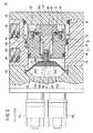
前記中間ブロック18bの内部には、図2〜図4に示されるように、ポートブロック18aとエンドブロック18cとによって閉塞された縦断面円形状の第1室22が形成され、前記第1室22に沿って縦断面円形状のピストン24が軸方向に沿って変位自在に設けられる。なお、図1ではボデイ16を横置き状態に設置しているため、以下の説明において軸方向とは水平方向(横方向)を示すものとする。As shown in FIGS. 2 to 4,a
前記ピストン24は、断面円形状の円柱体からなり内部に軸方向に沿って延在する小径孔部26a及び大径孔部26bによって後述する間接媒体28が進入可能な第2室30が形成されたピストン本体32と、複数のねじ部材34を介して前記ピストン本体32の一端面に面一且つ一体的に結合されることにより、前記第2室30を閉塞する閉塞プレート36とから構成される。前記ピストン本体32の外周面には、外方向に向かって所定長だけ突出する環状突部38が形成され、前記環状突部38が中間ブロック18bの内壁に形成された環状段部40に当接することにより、流体を吐出する際のピストン24の変位が規制される(図4参照)。 The
前記ピストン本体32と閉塞プレート36との間には、該ピストン本体32と閉塞プレート36との結合部分を気密乃至液密に保持する第2シール部材42が設けられ、前記第2室30に進入した間接媒体28がピストン24の受圧面側に進入することが前記第2シール部材42によって好適に阻止される。前記ピストン本体32の環状突部38には、溝部を介してピストンパッキン44が装着され、前記ピストンパッキン44は中間ブロック18bの内壁面に沿って摺動自在に設けられる。なお、ピストン本体32の外周面には、溝部を介して第3シール部材46が装着される。 A
ボデイ16の内部には、ポートブロック18aと中間ブロック18bとの間で挟持された略楕円形状のダイヤフラム48が張設され、前記ダイヤフラム48は、例えば、ウレタンゴム等の弾性材料によって撓曲自在に形成される。この場合、前記ダイヤフラム48とポートブロック18aの内壁との間でポンプ室50が形成され、前記ポンプ室50は、第1及び第2通路52a、52bを介して第1及び第2継手部材12a、12bに設けられた吐出ポート54a及び吸引ポート54bとそれぞれ連通するように設けられる。前記ダイヤフラム48の形状は、略楕円形状に限定されるものではなく、円形等の他の形状であってもよい。 A substantially
なお、前記第1及び第2通路52a、52bには、それぞれ、図示しないチェック弁が配設され、ポンプ室50から吸引ポート54b側への逆流及び吐出ポート54aからポンプ室50側への逆流がそれぞれ前記チェック弁によって好適に阻止される。 Each of the first and
前記ポンプ室50は、第1及び第2通路52a、52bが形成されたポートブロック18aのフラット面からダイヤフラム48側に向かって徐々に拡径する傾斜面56を有する。The
前記ダイヤフラム48は、厚肉に形成された中央部48aと、前記中央部48aに連続し薄肉に形成されてボデイ16に固定される周縁部48bと、前記中央部48aから軸方向に沿って突出し外周面に雄ねじが形成された連結部48cとが一体的に構成される。 The
さらに、前記ダイヤフラム48には、前記連結部48cを介して連結され該ダイヤフラム48と一体的に変位する変位部材58が設けられる。前記変位部材58は、ピストン本体32に形成された小径孔部26aを挿通してピストン本体32の第2室30内に臨むように設けられる。前記変位部材58にはフランジ部58aが形成され、一端部が前記フランジ部58aに係着され他端部がピストン本体32の環状段部に係着された復帰用スプリング60が設けられる。 Further, the
この復帰用スプリング60は、ピストン24が初期位置側に変位して流体を吸引する際、変位部材58をそのばね力で押圧することにより、ピストン24を初期位置に復帰させるためのものである。 The
閉塞プレート36が連結されていないピストン24の軸方向に沿ったフラットな端面とダイヤフラム48との間の空間部には、例えば、オイル等の非圧縮性流体からなる間接媒体28が充填される。この場合、前記間接媒体28は、ダイヤフラム48、第2及び第3シール部材42、46のシール機能によってダイヤフラム48とピストン24の端面との間、及びピストン本体32の小径孔部26aと変位部材58との間のクリアランスを介してピストン本体32内の閉塞された第2室30内に進入するように設けられる。前記非圧縮性流体である間接媒体28は、ピストン24とダイヤフラム48との間の空間部全体に充填されて容積変化しないものとする。 A space portion between the flat end surface along the axial direction of the
なお、前記間接媒体28と前記ダイヤフラム48との間には、例えば、ウレタンゴム等の弾性材料によってシート状に形成されて該ダイヤフラム48を保護する保護部材62が設けられる。前記保護部材62は、前記ダイヤフラム48と同様に、ポートブロック18aと中間ブロック18bとの間で挟持される。 A
本発明の実施の形態に係る定量吐出ポンプ10は、基本的には以上のように構成されるものであり、次にその動作並びに作用効果について説明する。なお、図2に示されるように、ポンプ室50には既に所定量の流体Aが吸引されてダイヤフラム48がピストン24側に凹状に窪み、且つダイヤフラム48に連結された変位部材58のフランジ部58aがピストン24の閉塞プレート36に当接した状態を初期位置として説明する。The
まず、継手部材12bの吸引ポート54bに図示しないチューブを介して、例えば、図示しない半導体のコーティング液供給源を接続し、一方、継手部材12aの吐出ポート54aに図示しないチューブを介して、例えば、図示しないコーティング液滴下装置を接続する。 First, for example, a semiconductor coating liquid supply source (not shown) is connected to the
次に、図示しないパイロットエア供給源を付勢し、一方のパイロット圧供給ポート14aにパイロットエアを供給する。その際、他方のパイロット圧供給ポート14bは大気開放状態となっている。前記パイロットエアは、ピストン24とエンドブロック18cとの間に供給され、ピストン24の閉塞プレート36及び環状突部38を受圧面としてピストン24がエンドブロック18cから離間する方向(矢印X1方向)へ押圧する。 Next, a pilot air supply source (not shown) is energized to supply pilot air to one pilot
前記ピストン24が矢印X1方向へ変位することにより、該ピストン24のフラットな端面によって間接媒体28が押圧され、さらに前記間接媒体28を介してダイヤフラム48が押圧されることにより、ピストン24の変位に連動してダイヤフラム48が該ピストン24の変位方向側に向かって撓曲する。前記ダイヤフラム48が撓曲することによりポンプ室50内の流体Aが吐出ポート54aを介して所定量だけ外部に吐出される。When the
ここで、ピストン24がパイロット圧によって押圧されて所定量だけ変位した場合におけるダイヤフラム48及びピストン24の軸方向の変位量をそれぞれ比較すると、ダイヤフラム48の中央部48a及び連結部48cの軸方向への変位量は、ピストン24の軸方向への変位量に対して大きくなるように設定されている。 Here, when the displacement amounts in the axial direction of the
すなわち、初期位置において、楕円形状からなる前記ダイヤフラム48は凹状にピストン24側に窪んでいると共に外周縁部がボデイ16に固定されているため、ダイヤフラム48の軸方向に対する変位量は縦断面円形状のピストン24と同一とならず、ピストン24よりも大きくなるからである。 That is, at the initial position, the
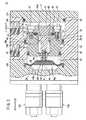
従って、図3に示されるように、パイロット圧の作用下にピストン24が所定量だけ変位した場合、初期位置においてピストン24の閉塞プレート36に当接していた変位部材58は、前記ピストン24の軸方向変位量よりも大きく変位して前記閉塞プレート36から所定距離だけ離間し、前記閉塞プレート36と変位部材58との間に間接媒体28が進入する。 Therefore, as shown in FIG. 3, when the
この結果、ピストン24の変位が非圧縮性流体からなる間接媒体28を通じてダイヤフラム48に伝達されることにより、ピストン24の変位流量(軸方向への変位量と受圧面積とを乗算したもの)と、ダイヤフラム48によって押圧されてポンプ室50から吐出ポート54aを介して吐出される流体Aの流量(吐出量)とが同一に設定される。 As a result, the displacement of the
換言すると、パイロット圧の作用によるピストン24の軸方向変位による容積変化(軸方向への変位量と受圧面積とを乗算したもの)と、ポンプ室50から流体Aを吐出させるためのダイヤフラム48の軸方向変位による容積変化とが、非圧縮性流体である間接媒体28を介在させることにより同一に設定されるため、ピストン24の容積変化に対応する吐出量を高精度に一定とすることができる。 In other words, the volume change due to the axial displacement of the
この場合、パイロット圧は一定の圧力でよいため、従来のようにピストン24の変位量を検出し前記変位量に対応してパイロット圧をフィードバック制御することが不要となる。 In this case, since the pilot pressure may be a constant pressure, it is not necessary to detect the displacement amount of the
ポンプ室50の内部の流体Aが図示しないチューブを介して吐出ポート54aに接続された前記コーティング液滴下装置へと吐出され、常に一定量の流体A(例えば、コーティング液)が半導体ウェハに対して滴下される。吐出ポート54aから吐出される流体Aの流量がピストン24の変位流量に対応して、常に一定となるように高精度な流体Aの流量制御を行うことができる。 The fluid A inside the
この場合、ピストン24の押圧力は非圧縮性流体である間接媒体28を介在させてダイヤフラム48を撓曲させているため、流体Aの脈動が生じることなく高精度に吐出させることができる。 In this case, since the
さらにまた、ポンプ室50の内部に流通された流体Aが液体の場合であっても、前記流体Aをポンプ室50より外部へと吐出した後、前記ポンプ室50に残存することがない。そのため、前記液体がダイヤフラム48に付着して液溜まりが生じることが防止される。 Furthermore, even when the fluid A circulated inside the
なお、所定量の流体Aを吐出ポート54aから吐出した後、流体Aを吸引するためには、パイロットエアの供給を一方のパイロット圧供給ポート14aから他方のパイロット圧供給ポート14bへと切り換え、一方のパイロット圧供給ポート14aを大気開放状態とする。 In order to suck the fluid A after discharging a predetermined amount of fluid A from the
他方のパイロット圧供給ポート14bから供給されたパイロットエアによってピストン24は矢印X2方向に変位して図1に示す初期位置に復帰し、吸引ポート54bを介してポンプ室50に所定量の流体Aが吸引され、前述した吐出工程に移行する。 With the pilot air supplied from the other pilot
10…定量吐出ポンプ 12a、12b…継手部材
14a、14b…パイロット圧供給ポート 16…ボデイ
22…第1室 24…ピストン
26a…小径孔部 26b…大径孔部
28…間接媒体 30…第2室
32…ピストン本体 36…閉塞プレート
48…ダイヤフラム 50…ポンプ室
58…変位部材 60…復帰用スプリング
62…保護部材 A…流体DESCRIPTION OF
Claims (1)
Translated fromJapaneseパイロット圧の作用下に前記ボデイの内部に形成された第1室に沿って変位自在に設けられると共に、該第1室に形成された環状段部に対して変位終端位置で当接する環状突部が外周面に設けられたピストンと、
非圧縮性流体からなり、流体を吐出する際に前記ピストンによって押圧される間接媒体と、
前記間接媒体に連動して撓曲し、前記ポンプ室に充填された流体を押圧することによりピストンの変位量に対応した流体を吐出させるダイヤフラムと、
を備え、
前記ピストンの内部には第2室が形成され、前記間接媒体が、前記ピストンの前記ダイヤフラムに対向するフラットな端面の中心に形成された孔部から該第2室に進入可能に設けられると共に、該第2室には、前記孔部を挿通して前記ダイヤフラムに連結された変位部材が進退自在に設けられ、
前記吐出ポートから流体を吐出する際、前記ダイヤフラムの軸方向への変位量が前記ピストンの軸方向への変位量よりも大きく設定され、該ピストンの軸方向変位による容積変化と前記ダイヤフラムの軸方向変位による容積変化とが同一であり、
前記ポンプ室は、前記吸引ポートと連通する第1通路及び前記吐出ポートと連通する第2通路が形成され前記ダイヤフラムと対向するフラット面と、該フラット面から前記ダイヤフラム側に向かって徐々に拡径する傾斜面とを有し、
前記ダイヤフラムは、中央部と、該中央部に連続して形成されて前記ボデイに固定される周縁部とを有し、
前記ピストンが変位終端位置に来たときに、前記ダイヤフラムの前記中央部が前記フラット面に押し付けられ、前記ダイヤフラムの周縁部が前記傾斜面に押し付けられる、ことを特徴とするポンプ装置。A body having a suction port for sucking fluid and a discharge port for discharging fluid, and having a pump chamber formed therein;
Abutting annular collision at the displacement terminal end position relative to the first chamber is disposed displaceably along theRutotomoni, annular stepped portion formed in the first chamber which is formed inside the body under the action of the pilot pressure A pistonprovided on theouter peripheral surface ,
An indirect medium consisting of an incompressible fluid and pressed by the piston when the fluid is discharged;
A diaphragm that bends in conjunction with the indirect medium and discharges fluid corresponding to the displacement of the piston by pressing the fluid filled in the pump chamber;
With
A second chamber is formed inside the piston, and the indirect medium is provided so as to be able to enter the second chamber from a hole formed at the center of a flat end surface facing the diaphragm of the piston. In the second chamber, a displacement member that is inserted through the hole and connected to the diaphragm is provided so as to freely advance and retract.
When the fluid is discharged from the discharge port, the displacement amount in the axial direction of the diaphragm is set larger than the displacement amount in the axial direction of the piston, and the volume change due to the axial displacement of the piston and the axial direction of the diaphragm The volume change due to displacement is the same,
The pump chamber is formed with a first passage that communicates with the suction port and a second passage that communicates with the discharge port. The flat surface faces the diaphragm, and the diameter gradually increases from the flat surface toward the diaphragm side. And an inclined surface that
The diaphragm has a central portion, and a peripheral edge portion formed continuously from the central portion and fixed to the body,
The pump device, wherein when the piston comes to a displacement end position, the central portion of the diaphragm is pressed against the flat surface, and a peripheral portion of the diaphragm is pressed against the inclined surface.
Priority Applications (6)
| Application Number | Priority Date | Filing Date | Title |
|---|---|---|---|
| JP2004213599AJP4587098B2 (en) | 2004-07-21 | 2004-07-21 | Pump device |
| TW094122633ATWI273170B (en) | 2004-07-21 | 2005-07-05 | Pump apparatus |
| DE102005033192.0ADE102005033192B4 (en) | 2004-07-21 | 2005-07-13 | pumping device |
| US11/181,980US7758321B2 (en) | 2004-07-21 | 2005-07-15 | Pump apparatus |
| KR1020050066436AKR100687539B1 (en) | 2004-07-21 | 2005-07-21 | Pump device |
| CN2005100859478ACN1724869B (en) | 2004-07-21 | 2005-07-21 | pump device |
Applications Claiming Priority (1)
| Application Number | Priority Date | Filing Date | Title |
|---|---|---|---|
| JP2004213599AJP4587098B2 (en) | 2004-07-21 | 2004-07-21 | Pump device |
Publications (2)
| Publication Number | Publication Date |
|---|---|
| JP2006029302A JP2006029302A (en) | 2006-02-02 |
| JP4587098B2true JP4587098B2 (en) | 2010-11-24 |
Family
ID=35668768
Family Applications (1)
| Application Number | Title | Priority Date | Filing Date |
|---|---|---|---|
| JP2004213599AExpired - LifetimeJP4587098B2 (en) | 2004-07-21 | 2004-07-21 | Pump device |
Country Status (6)
| Country | Link |
|---|---|
| US (1) | US7758321B2 (en) |
| JP (1) | JP4587098B2 (en) |
| KR (1) | KR100687539B1 (en) |
| CN (1) | CN1724869B (en) |
| DE (1) | DE102005033192B4 (en) |
| TW (1) | TWI273170B (en) |
Families Citing this family (18)
| Publication number | Priority date | Publication date | Assignee | Title |
|---|---|---|---|---|
| KR100856017B1 (en)* | 2008-04-11 | 2008-09-02 | (주)용성엔지니어링 | Fluid ejection part structure of pulsation pump |
| KR101667067B1 (en) | 2008-10-22 | 2016-10-17 | 그라코 미네소타 인크. | Portable airless sprayer |
| JP5419008B2 (en) | 2009-04-28 | 2014-02-19 | Smc株式会社 | Pump device |
| US8540743B2 (en)* | 2010-12-22 | 2013-09-24 | Alcon Research, Ltd. | Hydraulic vitrectomy probe |
| WO2015031884A1 (en)* | 2013-08-30 | 2015-03-05 | Flow Control Llc. | High viscosity portion pump |
| US9638185B2 (en) | 2014-02-07 | 2017-05-02 | Graco Minnesota Inc. | Pulseless positive displacement pump and method of pulselessly displacing fluid |
| GB201601194D0 (en) | 2016-01-22 | 2016-03-09 | Carlisle Fluid Tech Inc | Active surge chamber |
| CN105971859A (en)* | 2016-07-19 | 2016-09-28 | 中国有色(沈阳)泵业有限公司 | Load shedding system for heavy load membrane pump |
| US11007545B2 (en) | 2017-01-15 | 2021-05-18 | Graco Minnesota Inc. | Handheld airless paint sprayer repair |
| US11022106B2 (en) | 2018-01-09 | 2021-06-01 | Graco Minnesota Inc. | High-pressure positive displacement plunger pump |
| CN112368082B (en) | 2018-04-10 | 2022-11-08 | 固瑞克明尼苏达有限公司 | Handheld airless sprayer for paints and other coatings |
| JP7041416B2 (en) | 2019-03-22 | 2022-03-24 | Smc株式会社 | Fluid control valve |
| EP3976270A1 (en) | 2019-05-31 | 2022-04-06 | Graco Minnesota Inc. | Handheld fluid sprayer |
| AU2021246059A1 (en) | 2020-03-31 | 2022-10-06 | Graco Minnesota Inc. | Electrically operated displacement pump |
| EP4127475B1 (en) | 2020-03-31 | 2024-10-23 | Graco Minnesota Inc. | Electrically operated pump for a plural component spray system |
| US10968903B1 (en) | 2020-06-04 | 2021-04-06 | Graco Minnesota Inc. | Handheld sanitary fluid sprayer having resilient polymer pump cylinder |
| US10926275B1 (en) | 2020-06-25 | 2021-02-23 | Graco Minnesota Inc. | Electrostatic handheld sprayer |
| CN113898564B (en)* | 2021-09-08 | 2024-07-05 | 山东隆华新材料股份有限公司 | Diaphragm vacuum pump |
Family Cites Families (26)
| Publication number | Priority date | Publication date | Assignee | Title |
|---|---|---|---|---|
| US3416461A (en)* | 1966-09-01 | 1968-12-17 | Hills Mccanna Co | Diaphragm pump |
| US3680981A (en)* | 1970-12-21 | 1972-08-01 | Josef Wagner | Pump and method of driving same |
| US3775030A (en)* | 1971-12-01 | 1973-11-27 | Wanner Engineering | Diaphragm pump |
| US3769879A (en)* | 1971-12-09 | 1973-11-06 | A Lofquist | Self-compensating diaphragm pump |
| US4068982A (en)* | 1976-12-20 | 1978-01-17 | Graco Inc. | Charge control valve and piston assembly for diaphragm pump |
| IT1130115B (en) | 1980-04-15 | 1986-06-11 | Olivetti & Co Spa | ACTUATION DEVICE FOR TWO FUNCTIONS OF WRITING MACHINES |
| JPS56161190U (en)* | 1980-04-30 | 1981-12-01 | ||
| JPS5797085A (en)* | 1980-12-06 | 1982-06-16 | Hiroshi Kuroda | Vibration pump |
| JPS62102880A (en) | 1985-10-30 | 1987-05-13 | 松下電器産業株式会社 | Method for washing metal member slid with magnetic tape |
| JPS62102880U (en) | 1985-12-19 | 1987-06-30 | ||
| JP2698851B2 (en)* | 1987-02-24 | 1998-01-19 | 東京エレクトロン 株式会社 | Diaphragm pump |
| DE3706338A1 (en)* | 1987-02-27 | 1988-09-08 | Wagner Gmbh J | DIAPHRAGM PUMP DEVICE |
| DE3708868A1 (en)* | 1987-03-18 | 1988-10-06 | Ott Kg Lewa | METHOD AND DEVICE FOR STARTING A HYDRAULIC DIAPHRAGM PUMP AGAINST LOAD |
| JPH0198773A (en)* | 1987-09-22 | 1989-04-17 | Yoshinobu Koiwa | Valve device |
| JPH01203672A (en)* | 1988-02-03 | 1989-08-16 | Karl Eickmann | High pressure pump or compressor device |
| US4828646A (en)* | 1988-05-26 | 1989-05-09 | Chung Nan Y | Method and apparatus for tabbing tape |
| WO1991011616A1 (en)* | 1990-02-01 | 1991-08-08 | Wanner Engineering, Inc. | Improved system for pumping fluid |
| JPH06129357A (en)* | 1991-05-29 | 1994-05-10 | Clair Cunningham Christie St | Diaphragm type pumping plant |
| JP3067412B2 (en) | 1992-08-28 | 2000-07-17 | トヨタ自動車株式会社 | Diaphragm pump |
| US5707219A (en)* | 1995-10-04 | 1998-01-13 | Wanner Engineering | Diaphragm pump |
| JP3701367B2 (en)* | 1996-02-22 | 2005-09-28 | Smc株式会社 | Poppet valve |
| JP2926473B2 (en) | 1996-05-20 | 1999-07-28 | 日機装株式会社 | Hydraulic diaphragm pump |
| JPH1047234A (en)* | 1996-08-05 | 1998-02-17 | Koganei Corp | Quantitative delivery pump |
| GB9713456D0 (en)* | 1996-12-11 | 1997-08-27 | D I S | A drive device |
| JP4080632B2 (en) | 1999-04-22 | 2008-04-23 | 藤倉ゴム工業株式会社 | Pneumatic cylinder device |
| EP1219833B1 (en)* | 2001-01-02 | 2007-07-25 | Medela Holding AG | Diaphragm pump |
- 2004
- 2004-07-21JPJP2004213599Apatent/JP4587098B2/ennot_activeExpired - Lifetime
- 2005
- 2005-07-05TWTW094122633Apatent/TWI273170B/ennot_activeIP Right Cessation
- 2005-07-13DEDE102005033192.0Apatent/DE102005033192B4/ennot_activeExpired - Lifetime
- 2005-07-15USUS11/181,980patent/US7758321B2/enactiveActive
- 2005-07-21KRKR1020050066436Apatent/KR100687539B1/ennot_activeExpired - Lifetime
- 2005-07-21CNCN2005100859478Apatent/CN1724869B/ennot_activeExpired - Lifetime
Also Published As
| Publication number | Publication date |
|---|---|
| TWI273170B (en) | 2007-02-11 |
| CN1724869A (en) | 2006-01-25 |
| DE102005033192A1 (en) | 2006-02-16 |
| US20060027606A1 (en) | 2006-02-09 |
| US7758321B2 (en) | 2010-07-20 |
| KR100687539B1 (en) | 2007-03-02 |
| CN1724869B (en) | 2010-05-12 |
| DE102005033192B4 (en) | 2014-05-15 |
| TW200606337A (en) | 2006-02-16 |
| JP2006029302A (en) | 2006-02-02 |
| KR20060046553A (en) | 2006-05-17 |
Similar Documents
| Publication | Publication Date | Title |
|---|---|---|
| JP4587098B2 (en) | Pump device | |
| JP4531563B2 (en) | Peristaltic micropump | |
| ES2689916T3 (en) | High pressure valve assembly | |
| JP4035728B2 (en) | Suck back valve | |
| JP4547368B2 (en) | Chemical supply device | |
| TWI794396B (en) | liquid supply device | |
| US20040076526A1 (en) | Pump apparatus | |
| JP6420338B2 (en) | Negative pressure handling device or negative pressure clamping device, and valve for negative pressure handling device | |
| JP5114527B2 (en) | Liquid supply device | |
| KR102155310B1 (en) | High precision diaphragm type pulseless metering pump using face cam | |
| EP3133284B1 (en) | Disposable diaphragm valve | |
| KR20190142740A (en) | Fluid pumps and related systems and methods | |
| US8382451B2 (en) | Pump apparatus | |
| JP5248267B2 (en) | pump | |
| JP2007154767A (en) | Tube pump | |
| KR101414080B1 (en) | Drug solution dispensing device | |
| JP4566989B2 (en) | Chemical supply device | |
| JP3568866B2 (en) | Reciprocating pump | |
| TWI685613B (en) | A pump, a coating apparatus | |
| EP4474649A1 (en) | Mounting structure for diaphragm and retainer | |
| CN111065466A (en) | Fluid Dispenser with Zero Displacement Seal | |
| KR101837001B1 (en) | An Improved Pressing Device and Method for Pumping Chemical Liquids, and A Feeding Device and Method of Chemical Liquids Having the Same | |
| JP4276757B2 (en) | Liquid discharge pump | |
| CN113728183B (en) | Diaphragm and fluid instrument | |
| WO2006090773A1 (en) | Valve and variable volume pump with the valve |
Legal Events
| Date | Code | Title | Description |
|---|---|---|---|
| A621 | Written request for application examination | Free format text:JAPANESE INTERMEDIATE CODE: A621 Effective date:20060413 | |
| A977 | Report on retrieval | Free format text:JAPANESE INTERMEDIATE CODE: A971007 Effective date:20090213 | |
| A131 | Notification of reasons for refusal | Free format text:JAPANESE INTERMEDIATE CODE: A131 Effective date:20090714 | |
| A521 | Request for written amendment filed | Free format text:JAPANESE INTERMEDIATE CODE: A523 Effective date:20090911 | |
| A02 | Decision of refusal | Free format text:JAPANESE INTERMEDIATE CODE: A02 Effective date:20100302 | |
| A521 | Request for written amendment filed | Free format text:JAPANESE INTERMEDIATE CODE: A523 Effective date:20100602 | |
| A911 | Transfer to examiner for re-examination before appeal (zenchi) | Free format text:JAPANESE INTERMEDIATE CODE: A911 Effective date:20100714 | |
| TRDD | Decision of grant or rejection written | ||
| A01 | Written decision to grant a patent or to grant a registration (utility model) | Free format text:JAPANESE INTERMEDIATE CODE: A01 Effective date:20100810 | |
| A01 | Written decision to grant a patent or to grant a registration (utility model) | Free format text:JAPANESE INTERMEDIATE CODE: A01 | |
| A61 | First payment of annual fees (during grant procedure) | Free format text:JAPANESE INTERMEDIATE CODE: A61 Effective date:20100827 | |
| R150 | Certificate of patent or registration of utility model | Free format text:JAPANESE INTERMEDIATE CODE: R150 Ref document number:4587098 Country of ref document:JP Free format text:JAPANESE INTERMEDIATE CODE: R150 | |
| FPAY | Renewal fee payment (event date is renewal date of database) | Free format text:PAYMENT UNTIL: 20130917 Year of fee payment:3 | |
| R250 | Receipt of annual fees | Free format text:JAPANESE INTERMEDIATE CODE: R250 | |
| R250 | Receipt of annual fees | Free format text:JAPANESE INTERMEDIATE CODE: R250 | |
| R250 | Receipt of annual fees | Free format text:JAPANESE INTERMEDIATE CODE: R250 | |
| R250 | Receipt of annual fees | Free format text:JAPANESE INTERMEDIATE CODE: R250 | |
| R250 | Receipt of annual fees | Free format text:JAPANESE INTERMEDIATE CODE: R250 | |
| R250 | Receipt of annual fees | Free format text:JAPANESE INTERMEDIATE CODE: R250 | |
| R250 | Receipt of annual fees | Free format text:JAPANESE INTERMEDIATE CODE: R250 | |
| R250 | Receipt of annual fees | Free format text:JAPANESE INTERMEDIATE CODE: R250 | |
| R250 | Receipt of annual fees | Free format text:JAPANESE INTERMEDIATE CODE: R250 | |
| R250 | Receipt of annual fees | Free format text:JAPANESE INTERMEDIATE CODE: R250 | |
| R250 | Receipt of annual fees | Free format text:JAPANESE INTERMEDIATE CODE: R250 | |
| EXPY | Cancellation because of completion of term |