JP4587089B2 - Damping force adjustable hydraulic shock absorber - Google Patents
Damping force adjustable hydraulic shock absorberDownload PDFInfo
- Publication number
- JP4587089B2 JP4587089B2JP2000163230AJP2000163230AJP4587089B2JP 4587089 B2JP4587089 B2JP 4587089B2JP 2000163230 AJP2000163230 AJP 2000163230AJP 2000163230 AJP2000163230 AJP 2000163230AJP 4587089 B2JP4587089 B2JP 4587089B2
- Authority
- JP
- Japan
- Prior art keywords
- passage
- damping force
- valve
- pilot
- piston
- Prior art date
- Legal status (The legal status is an assumption and is not a legal conclusion. Google has not performed a legal analysis and makes no representation as to the accuracy of the status listed.)
- Expired - Fee Related
Links
Images

Classifications
- F—MECHANICAL ENGINEERING; LIGHTING; HEATING; WEAPONS; BLASTING
- F16—ENGINEERING ELEMENTS AND UNITS; GENERAL MEASURES FOR PRODUCING AND MAINTAINING EFFECTIVE FUNCTIONING OF MACHINES OR INSTALLATIONS; THERMAL INSULATION IN GENERAL
- F16F—SPRINGS; SHOCK-ABSORBERS; MEANS FOR DAMPING VIBRATION
- F16F9/00—Springs, vibration-dampers, shock-absorbers, or similarly-constructed movement-dampers using a fluid or the equivalent as damping medium
- F16F9/32—Details
- F16F9/44—Means on or in the damper for manual or non-automatic adjustment; such means combined with temperature correction
- F16F9/46—Means on or in the damper for manual or non-automatic adjustment; such means combined with temperature correction allowing control from a distance, i.e. location of means for control input being remote from site of valves, e.g. on damper external wall
- F—MECHANICAL ENGINEERING; LIGHTING; HEATING; WEAPONS; BLASTING
- F16—ENGINEERING ELEMENTS AND UNITS; GENERAL MEASURES FOR PRODUCING AND MAINTAINING EFFECTIVE FUNCTIONING OF MACHINES OR INSTALLATIONS; THERMAL INSULATION IN GENERAL
- F16F—SPRINGS; SHOCK-ABSORBERS; MEANS FOR DAMPING VIBRATION
- F16F9/00—Springs, vibration-dampers, shock-absorbers, or similarly-constructed movement-dampers using a fluid or the equivalent as damping medium
- F16F9/32—Details
- F16F9/34—Special valve constructions; Shape or construction of throttling passages
- F16F9/348—Throttling passages in the form of annular discs or other plate-like elements which may or may not have a spring action, operating in opposite directions or singly, e.g. annular discs positioned on top of the valve or piston body
- F16F9/3484—Throttling passages in the form of annular discs or other plate-like elements which may or may not have a spring action, operating in opposite directions or singly, e.g. annular discs positioned on top of the valve or piston body characterised by features of the annular discs per se, singularly or in combination
Landscapes
- Engineering & Computer Science (AREA)
- General Engineering & Computer Science (AREA)
- Mechanical Engineering (AREA)
- Fluid-Damping Devices (AREA)
Description
Translated fromJapanese【0001】
【発明の属する技術分野】
本発明は、自動車等の車両の懸架装置に装着される減衰力調整式油圧緩衝器に関するものである。
【0002】
【従来の技術】
自動車等の車両の懸架装置に装着される油圧緩衝器には、路面状況、走行状況等に応じて乗り心地や操縦安定性を向上させるために減衰力を適宜調整できるようにした減衰力調整式油圧緩衝器がある。
【0003】
減衰力調整式油圧緩衝器は、一般に、油液を封入したシリンダ内にピストンロッドを連結したピストンを摺動可能に嵌装してシリンダ内を2室に画成し、ピストン部にシリンダ内の2室を連通させる主油路およびバイパス通路を設け、主油路にはオリフィスおよびディスクバルブからなる減衰力発生機構を設け、バイパス通路には、その通路面積を調整する減衰力調整弁を設けた構成となっている。
【0004】
そして、減衰力調整弁によってバイパス通路を開いてシリンダ内の2室間の油液の流通抵抗を小さくすることにより減衰力を小さくし、また、バイパス通路を閉じて2室間の流通抵抗を大きくすることにより減衰力を大きくする。このように、減衰力調整弁の開閉により減衰力特性を適宜調整することができる。
【0005】
しかしながら、上記のようにバイパス通路の通路面積によって減衰力を調整するものでは、ピストン速度の低速域においては、減衰力は油路のオリフィスの絞りに依存するので、減衰力特性を大きく変化させることができるが、ピストン速度の中高速域においては、減衰力が主油路の減衰力発生機構(ディスクバルブ等)の開度に依存するため、減衰力特性を大きく変化させることができない。
【0006】
そこで、例えば特開平7‐332425号公報に記載されているように、伸び縮み側共通の主油路の減衰力発生機構であるディスクバルブの背部に圧力室(パイロット室)を形成し、この圧力室を固定オリフィスを介してディスクバルブの上流側のシリンダ室に連通させ、また、可変オリフィス(流量制御弁)を介してディスクバルブの下流側のシリンダ室に連通させるようにしたものが知られている。
【0007】
この減衰力調整式油圧緩衝器によれば、可変オリフィスを開閉することにより、シリンダ内の2室間の連通路面積を調整するとともに、可変オリフィスで生じる圧力損失によって圧力室の圧力を変化させてディスクバルブの開弁初期圧力を変化させることができる。このようにして、オリフィス特性(減衰力がピストン速度の2乗にほぼ比例する)およびバルブ特性(減衰力がピストン速度にほぼ比例する)を調整することができ、減衰力特性の調整範囲を広くすることができる。
【0008】
【発明が解決しようとする課題】
しかしながら、上記公報記載のパイロット室を有する減衰力調整式油圧緩衝器では、次のような問題があった。ピストンロッドのストローク方向が伸び側から縮み側または縮み側から伸び側へ切換るとき、シリンダ内の油液の圧力が急激に変動するが、この圧力変動が油路を介してパイロット室に伝達されて、ディスクバルブの開弁圧力が変動するため、安定した減衰力を得ることが困難になる。
【0009】
本発明は、上記の点に鑑みて成されたものであり、ピストンロッドのストローク方向が変化する際にも、パイロット室の圧力変動を抑制して安定した減衰力を得ることができる減衰力調整式油圧緩衝器を提供することを目的とする。
【0010】
【課題を解決するための手段】
上記の課題を解決するために、本発明の減衰力調整式油圧緩衝器は、油液が封入されたシリンダと、該シリンダ内に摺動可能に嵌装されたピストンと、一端がピストンに連結され、他端が前記シリンダの外部へ延出されたピストンロッドと、前記シリンダに接続され、前記ピストンの摺動によって油液を流通させる主通路と、該主通路と並列に設けられた副通路と、前記主通路の油液の流れを制御して減衰力を発生させるパイロット型減衰弁と、前記副通路の上流側に設けられた流路面積が変化しない固定オリフィスと、該副通路の前記固定オリフィスより下流側に設けられたアクチュエータへの通電電流によって開弁圧力を調整する圧力制御弁と、前記副通路の前記固定オリフィスと前記圧力制御弁との間を前記パイロット型減衰弁のパイロット室に連通させるパイロット通路と、該パイロット通路に設けられた絞り手段とを備えたことを特徴とする。
【0011】
このように構成したことにより、圧力制御弁によって副通路の油液の流れを制御して減衰力を調整するとともに、パイロット通路を介してパイロット室に伝達されるパイロット圧力を変化させてパイロット型減衰弁の開弁圧力を調整する。このとき、パイロット通路を介してパイロット室へ伝達される油液の圧力の変動が、絞り手段によって減衰される。
【0012】
【発明の実施の形態】
以下、本発明の一実施形態を図面に基づいて詳細に説明する。
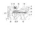
図1および図2に示すように、本実施形態の減衰力調整式油圧緩衝器1は、油液が封入されたシリンダ2内に、ピストン3が摺動可能に嵌装されており、このピストンによってシリンダ2内がシリンダ上室2aとシリンダ下室2bとの2室に画成されている。ピストン3の両端部には、後述する伸び側および縮み側減衰力発生機構4、5が取り付けられ、これらにピストンボルト6が挿通されてナット7によって固定されている。ピストンボルト6の基端部には、ピストンロッド8の一端部が連結され、ピストンロッド8の他端側は、シリンダ2の端部に設けられたロッドガイドおよびオイルシール(図示せず)に挿通されて外部へ延出されている。シリンダ2には、ピストンロッド8の伸縮に伴うその容積変化を吸収するためのリザーバ(図示せず)が接続されている。
【0013】
ピストン3には、シリンダ上下室2a、2b間を連通させる伸び側油路9(主通路)および縮み側油路10(主通路)が設けられている。そして、ピストンロッド8の伸び行程時には、伸び側油路9の油液の流れを伸び側減衰力発生機構4によって制御して減衰力を発生させ、縮み行程時には、縮み側油路10の油液の流動を縮み側減衰力発生機構5によって制御して減衰力を発生させる。
【0014】
伸び側減衰力発生機構4は、ディスクバルブ11(パイロット型減衰弁)、固定部材12および可動部材13を含み、これらによって、パイロット室14が形成されている。そして、ディスクバルブ11によって、伸び側油路9の油液の流れを制御して減衰力を発生させ、パイロット室14の圧力をディスクバルブ11の背面に作用させて、その開弁圧力を調整する。伸び側油路9は、オリフィス通路15および油路16を介してピストンボルト6の内部へ連通され、さらに、油路17および逆止弁18を介してシリンダ下室2bへ連通されている。これらのオリフィス通路15、油路16、17および逆止弁18によって、伸び側油路9をシリンダ下室2bへ連通させる伸び側副通路が形成され、ピストンボルト6内には、この副通路の油液の流れを制御する圧力制御弁19(調整弁)が設けられている。
【0015】
ピストンボルト6の外周部の凹部によって、オリフィス通路15と油路16との間に油室20が形成され、この油室20は、ディスクバルブ11の内周部に形成された切欠21および固定部材12に形成されたオリフィス溝22(絞り手段)を介してパイロット室14に連通されている。
【0016】
縮み側減衰力発生機構5は、ディスクバルブ23(パイロット型減衰弁)、固定部材24および可動部材25を含み、これらによって、パイロット室26が形成されている。そして、ディスクバルブ23によって、縮み側油路10の油液の流れを制御して減衰力を発生させ、パイロット室26の圧力をディスクバルブ23の背面に作用させて、その開弁圧力を調整する。縮み側油路10は、オリフィス通路27および油路28を介してピストンボルト6の内部へ連通され、さらに、油路29および逆止弁30を介してシリンダ上室2aへ連通されている。これら、オリフィス通路27、油路28、29および逆止弁30によって縮み側油路10をシリンダ上室2aへ連通させる縮み側副通路が形成され、ピストンボルト6内には、この副通路の油液の流れを制御する圧力制御弁31が設けられている。
【0017】
ピストンボルト6の外周部の凹部によって、オリフィス通路27と油路28との間に油室32が形成され、この油室32は、ディスクバルブ23の内周部に形成された切欠33および固定部材24に形成されたオリフィス溝34(絞り手段)を介してパイロット室26に連通されている。
【0018】
伸び側および縮み側の圧力制御弁19、31は、ピストンボルト6内に摺動可能に嵌装され、互いに当接されており、伸び側の圧力制御弁19の端部は、戻しばね35(圧縮ばね)によって押圧され、縮み側の圧力制御弁の端部は、ピストンロッド8内に設けられた比例ソレノイドアクチュエータ(図示せず)の作動ロッド36に当接されている。そして、比例ソレノイドアクチュエータへの通電電流によって伸び側および縮み側の圧力制御弁19、31の制御圧力を調整できるようになっている。
【0019】
以上のように構成した本実施形態の作用について次に説明する。
ピストンロッド8の伸び行程時には、ピストン3の移動にともない、シリンダ上室2a側の油液が加圧され、伸び側減衰力発生機構4のディスクバルブ11の開弁前(ピストン速度低速域)においては、伸び側油路9、オリフィス油路15、油室20、油路16、圧力制御弁19、油路17、逆止弁18を通ってシリンダ下室2b側へ流れる。シリンダ上室2a側の圧力がディスクバルブ11の開弁圧力に達すると(ピストン速度高速域)、ディスクバルブ11が開弁して、油液が伸び側油路9からシリンダ下室2bへ直接流れる。
【0020】
これにより、比例ソレノイドへの通電電流によって圧力制御弁19の開弁圧力を調整することにより、減衰力を直接制御することができる。このとき、圧力制御弁19の上流側の圧力が切欠21およびオリフィス溝22によってパイロット室14に伝達されるので、圧力制御弁19の開弁圧力とともにディスクバルブ11の開弁圧力が同時に同様に調整されることになり、ピストン低速域および高速域の減衰力を同時に調整することができる。
【0021】
また、ピストンロッド8の縮み行程時には、ピストン3の移動にともない、シリンダ下室2b側の油液が加圧され、縮み側減衰力発生機構5のディスクバルブ23の開弁前(ピストン速度低速域)においては、縮み側油路10、オリフィス油路27、油室32、油路28、圧力制御弁31、油路29、逆止弁30を通ってシリンダ上室2a側へ流れる。シリンダ下室2b側の圧力がディスクバルブ23の開弁圧力に達すると(ピアストン速度高速域)、ディスクバルブ23が開弁して、油液が縮み側油路10からシリンダ上室2aへ直接流れる。
【0022】
これにより、比例ソレノイドへの通電電流によって圧力制御弁31の開弁圧力を調整することにより、減衰力を直接制御することができる。このとき、圧力制御弁31の上流側の圧力が切欠33およびオリフィス溝34によってパイロット室26に伝達されるので、圧力制御弁31の開弁圧力とともにディスクバルブ23の開弁圧力が同時に同様に調整されることになり、ピストン低速域および高速域の減衰力を同時に調整することができる。
【0023】
このとき、伸びおよび縮み行程において、それぞれ、副通路すなわち油室20、32からパイロット室14、26に伝達される圧力は、オリフィス油路22、34によって絞られるので、副通路の急激な圧力変動に対して、パイロット室22、34の反応を鈍くすることができる。これにより、ピストンロッド8のストロークの方向が切換る際にピストン3付近に生じる急激な圧力の変動がパイロット室22、34に伝達されにくくなるので、圧力変動の影響による減衰力の変動を抑制して常に安定した減衰力を得ることができる。
【0024】
この場合のオリフィス油路22、34による応答遅れに関する時定数τは、次式によって表される。
τ=C/(Kν/V)
ここで、
V:パイロット室の容積
Kν:パイロット室の体積弾性係数
C:オリフィス油路における流量に対する差圧の係数を線形近似した値
この式から、オリフィス通路22、34の絞りを大きくする(Cの値を大きくする)ことによって、時定数τが大きくなり、圧力変動の影響を受けにくくなることが分かる。
【0026】
また、上記実施形態では、ピストン及びピストンロッド部にパイロット型減衰弁等を内蔵した減衰力調整式油圧緩衝器を示したが、これに限らず、本発明は、ピストンの上下室をシリンダ外部のバイパス通路にて連通させ、このバイパス通路にパイロット型減衰弁等を設けたタイプの減衰力調整式油圧緩衝器にも同様に適用することができる。
【0027】
【発明の効果】
以上詳述したように、本発明の減衰力調整油圧緩衝器によれば、副通路からパイロット型減衰弁のパイロット室にパイロット圧力を供給するパイロット通路にに絞り手段を設けたことにより、ピストンロッドのストローク方向が切換る際のシリンダ内の油液の圧力の急激な変動がパイロット室に伝達されにくくなるので、圧力変動の影響による減衰力の変動を抑制して常に安定した減衰力を得ることができる。
【図面の簡単な説明】
【図1】本発明の一実施形態に係る減衰力調整式油圧緩衝器の要部の縦断面図である。
【図2】図1の装置の縮み側減衰力発生機構の拡大図である。
【符号の説明】
1 減衰力調整式油圧緩衝器
2 シリンダ
3 ピストン
8 ピストンロッド
9 伸び側油路(主通路)
10 縮み側油路(主通路)
11,23 ディスクバルブ(パイロット型減衰弁)
21,33 切欠(パイロット通路)
22,34 オリフィス溝(絞り手段)
14,26 パイロット室
15,27 オリフィス油路(固定オリフィス)
16,17,28,29 油路(副通路)
19,31 圧力制御弁(調整弁)[0001]
BACKGROUND OF THE INVENTION
The present invention relates to a damping force adjusting hydraulic shock absorber mounted on a suspension device of a vehicle such as an automobile.
[0002]
[Prior art]
The hydraulic shock absorber mounted on the suspension system of a vehicle such as an automobile has a damping force adjustment type that allows the damping force to be adjusted appropriately in order to improve ride comfort and handling stability according to road surface conditions, driving conditions, etc. There is a hydraulic shock absorber.
[0003]
In general, a damping force adjusting type hydraulic shock absorber is slidably fitted with a piston connected to a piston rod in a cylinder filled with an oil liquid so as to slidably define the inside of the cylinder in two chambers. A main oil passage and a bypass passage for communicating the two chambers are provided, a damping force generating mechanism including an orifice and a disk valve is provided in the main oil passage, and a damping force adjusting valve for adjusting the passage area is provided in the bypass passage. It has a configuration.
[0004]
The damping force adjustment valve opens the bypass passage to reduce the fluid flow resistance between the two chambers in the cylinder to reduce the damping force, and closes the bypass passage to increase the passage resistance between the two chambers. To increase the damping force. Thus, the damping force characteristic can be adjusted as appropriate by opening and closing the damping force adjustment valve.
[0005]
However, in the case where the damping force is adjusted according to the passage area of the bypass passage as described above, since the damping force depends on the restriction of the orifice of the oil passage in the low speed region of the piston speed, the damping force characteristic is greatly changed. However, in the middle and high speed range of the piston speed, the damping force depends on the opening degree of the damping force generation mechanism (disk valve or the like) of the main oil passage, so that the damping force characteristic cannot be changed greatly.
[0006]
Therefore, for example, as described in JP-A-7-332425, a pressure chamber (pilot chamber) is formed at the back of the disc valve, which is a damping force generation mechanism for the main oil passage common to the expansion and contraction sides. It is known that the chamber communicates with the cylinder chamber upstream of the disk valve via a fixed orifice, and communicates with the cylinder chamber downstream of the disk valve via a variable orifice (flow control valve). Yes.
[0007]
According to this damping force adjustment type hydraulic shock absorber, by opening and closing the variable orifice, the communication passage area between the two chambers in the cylinder is adjusted, and the pressure in the pressure chamber is changed by the pressure loss generated in the variable orifice. The initial valve opening pressure of the disc valve can be changed. In this way, the orifice characteristic (the damping force is approximately proportional to the square of the piston speed) and the valve characteristic (the damping force is approximately proportional to the piston speed) can be adjusted, and the adjustment range of the damping force characteristic is widened. can do.
[0008]
[Problems to be solved by the invention]
However, the damping force adjusting hydraulic shock absorber having the pilot chamber described in the above publication has the following problems. When the stroke direction of the piston rod is switched from the expansion side to the contraction side or from the contraction side to the expansion side, the oil pressure in the cylinder fluctuates rapidly, but this pressure fluctuation is transmitted to the pilot chamber via the oil passage. As a result, the valve opening pressure of the disk valve fluctuates, making it difficult to obtain a stable damping force.
[0009]
The present invention has been made in view of the above points, and is a damping force adjustment capable of obtaining a stable damping force by suppressing the pressure fluctuation of the pilot chamber even when the stroke direction of the piston rod changes. An object of the present invention is to provide a hydraulic shock absorber.
[0010]
[Means for Solving the Problems]
In order to solve the above-described problems, a damping force adjusting hydraulic shock absorber according to the present invention includes a cylinder in which oil is sealed, a piston slidably fitted in the cylinder, and one end connected to the piston. A piston rod whose other end extends to the outside of the cylinder, a main passage connected to the cylinder and allowing fluid to flow by sliding of the piston,and a sub-passageprovided in parallel with the main passage A pilot-type damping valve that generates a damping force by controlling the flow of the oil liquid in the main passage, a fixed orifice thatis provided on the upstream side of the sub-passageand does not change, andthe sub-passage of the sub-passage a pressure control valve for adjusting the valve opening pressure by electric current suppliedfrom the fixed orifice to an actuator provided on thedownstream side, the pie of the pilot type damping valve between auxiliary passage said fixed orifice and said pressure control valve A pilot passage for communicating the Tsu preparative chamber, characterized by comprising a throttle means provided in the pilot passage.
[0011]
With this configuration, the damping force is adjusted by controlling the flow of the oil liquid in the sub-passage by thepressure control valve , and the pilot pressure transmitted to the pilot chamber via the pilot passage is changed to make a pilot type damping. Adjust the valve opening pressure. At this time, the fluctuation of the pressure of the oil liquid transmitted to the pilot chamber through the pilot passage is attenuated by the throttle means.
[0012]
DETAILED DESCRIPTION OF THE INVENTION
Hereinafter, an embodiment of the present invention will be described in detail with reference to the drawings.
As shown in FIGS. 1 and 2, the damping force adjusting type hydraulic shock absorber 1 of the present embodiment has a
[0013]
The
[0014]
The extension-side damping
[0015]
An
[0016]
The compression-side damping
[0017]
An
[0018]
The expansion-side and contraction-side
[0019]
Next, the operation of the present embodiment configured as described above will be described.
During the extension stroke of the
[0020]
Thereby, the damping force can be directly controlled by adjusting the valve opening pressure of the
[0021]
Also, during the contraction stroke of the
[0022]
Thereby, the damping force can be directly controlled by adjusting the valve opening pressure of the
[0023]
At this time, in the expansion and contraction strokes, the pressure transmitted from the sub-passage, that is, the
[0024]
In this case, the time constant τ related to the response delay due to the
τ = C / (Kν / V)
here,
V: Volume of pilot room
Kν: Volumetric modulus of the pilot chamber
C: Linear approximation of the differential pressure coefficient with respect to the flow rate in the orifice oil passage From this equation, the time constant τ is increased by increasing the restriction of the
[0026]
Further, in the above embodiment, the damping force adjustment type hydraulic shock absorber in which the piston and the piston rod part include the pilot type damping valve is shown. However, the present invention is not limited to this, and the upper and lower chambers of the piston are arranged outside the cylinder. The present invention can be similarly applied to a damping force adjusting hydraulic shock absorber of a type in which communication is made in a bypass passage and a pilot type damping valve is provided in the bypass passage.
[0027]
【The invention's effect】
As described above in detail, according to the damping force adjusting hydraulic shock absorber of the present invention, the piston rod is provided with the throttle means in the pilot passage for supplying the pilot pressure from the auxiliary passage to the pilot chamber of the pilot type damping valve. Because the rapid fluctuation of the oil pressure in the cylinder when the stroke direction of the cylinder is switched is less likely to be transmitted to the pilot chamber, the fluctuation of the damping force due to the pressure fluctuation can be suppressed to always obtain a stable damping force. Can do.
[Brief description of the drawings]
FIG. 1 is a longitudinal sectional view of an essential part of a damping force adjusting hydraulic shock absorber according to an embodiment of the present invention.
FIG. 2 is an enlarged view of a contraction-side damping force generation mechanism of the apparatus of FIG.
[Explanation of symbols]
1 Damping force adjustable hydraulic shock absorber
2 cylinder
3 piston
8 Piston rod
9 Extension side oil passage (main passage)
10 Shrinkage side oil passage (main passage)
11,23 Disc valve (Pilot type damping valve)
21,33 Notch (pilot passage)
22,34 Orifice groove (throttle means)
14,26 Pilot room
15,27 Orifice oil passage (fixed orifice)
16, 17, 28, 29 Oil passage (sub-passage)
19,31 Pressure control valve (regulating valve)
Claims (1)
Translated fromJapanesePriority Applications (4)
| Application Number | Priority Date | Filing Date | Title |
|---|---|---|---|
| JP2000163230AJP4587089B2 (en) | 2000-05-31 | 2000-05-31 | Damping force adjustable hydraulic shock absorber |
| US09/866,713US6474454B2 (en) | 2000-05-31 | 2001-05-30 | Damping force control type hydraulic shock absorber |
| KR10-2001-0030000AKR100451289B1 (en) | 2000-05-31 | 2001-05-30 | Damping force adjustable hydraulic buffer |
| DE10126555ADE10126555C2 (en) | 2000-05-31 | 2001-05-31 | Damping force regulating hydraulic shock absorber |
Applications Claiming Priority (1)
| Application Number | Priority Date | Filing Date | Title |
|---|---|---|---|
| JP2000163230AJP4587089B2 (en) | 2000-05-31 | 2000-05-31 | Damping force adjustable hydraulic shock absorber |
Publications (2)
| Publication Number | Publication Date |
|---|---|
| JP2001343041A JP2001343041A (en) | 2001-12-14 |
| JP4587089B2true JP4587089B2 (en) | 2010-11-24 |
Family
ID=18667022
Family Applications (1)
| Application Number | Title | Priority Date | Filing Date |
|---|---|---|---|
| JP2000163230AExpired - Fee RelatedJP4587089B2 (en) | 2000-05-31 | 2000-05-31 | Damping force adjustable hydraulic shock absorber |
Country Status (4)
| Country | Link |
|---|---|
| US (1) | US6474454B2 (en) |
| JP (1) | JP4587089B2 (en) |
| KR (1) | KR100451289B1 (en) |
| DE (1) | DE10126555C2 (en) |
Cited By (1)
| Publication number | Priority date | Publication date | Assignee | Title |
|---|---|---|---|---|
| KR20150142907A (en)* | 2014-06-12 | 2015-12-23 | 주식회사 만도 | Damping force controlling shock absorber |
Families Citing this family (70)
| Publication number | Priority date | Publication date | Assignee | Title |
|---|---|---|---|---|
| DE10120918B4 (en)* | 2001-04-27 | 2011-05-05 | Continental Aktiengesellschaft | Electrically adjustable, semi-active damper control |
| JP3978707B2 (en)* | 2001-11-29 | 2007-09-19 | 株式会社日立製作所 | Damping force adjustable hydraulic shock absorber |
| JP3978708B2 (en)* | 2001-11-29 | 2007-09-19 | 株式会社日立製作所 | Damping force adjustable hydraulic shock absorber |
| AU2002328481A1 (en)* | 2002-09-05 | 2004-03-29 | Stromsholmen Ab | Tool for piercing nut |
| DE10319390B4 (en)* | 2003-04-30 | 2005-11-10 | Thyssenkrupp Bilstein Gmbh | Hydraulic shock absorber |
| CN100526674C (en)* | 2004-05-25 | 2009-08-12 | 日产自动车株式会社 | Hydraulic shock absorber |
| JP4318080B2 (en)* | 2004-06-07 | 2009-08-19 | 株式会社日立製作所 | Hydraulic shock absorber |
| JP4840557B2 (en)* | 2005-04-12 | 2011-12-21 | 日立オートモティブシステムズ株式会社 | Damping force adjustable hydraulic shock absorber |
| KR100791471B1 (en)* | 2006-02-20 | 2008-01-04 | 주식회사 만도 | Variable damping force valve and shock absorber using the same |
| US8627932B2 (en) | 2009-01-07 | 2014-01-14 | Fox Factory, Inc. | Bypass for a suspension damper |
| US10047817B2 (en) | 2009-01-07 | 2018-08-14 | Fox Factory, Inc. | Method and apparatus for an adjustable damper |
| US11306798B2 (en) | 2008-05-09 | 2022-04-19 | Fox Factory, Inc. | Position sensitive suspension damping with an active valve |
| US9033122B2 (en) | 2009-01-07 | 2015-05-19 | Fox Factory, Inc. | Method and apparatus for an adjustable damper |
| US8857580B2 (en) | 2009-01-07 | 2014-10-14 | Fox Factory, Inc. | Remotely operated bypass for a suspension damper |
| US10060499B2 (en) | 2009-01-07 | 2018-08-28 | Fox Factory, Inc. | Method and apparatus for an adjustable damper |
| US20100170760A1 (en) | 2009-01-07 | 2010-07-08 | John Marking | Remotely Operated Bypass for a Suspension Damper |
| US9452654B2 (en) | 2009-01-07 | 2016-09-27 | Fox Factory, Inc. | Method and apparatus for an adjustable damper |
| US20120305350A1 (en) | 2011-05-31 | 2012-12-06 | Ericksen Everet O | Methods and apparatus for position sensitive suspension damping |
| US8393446B2 (en) | 2008-08-25 | 2013-03-12 | David M Haugen | Methods and apparatus for suspension lock out and signal generation |
| US10036443B2 (en) | 2009-03-19 | 2018-07-31 | Fox Factory, Inc. | Methods and apparatus for suspension adjustment |
| US9140325B2 (en) | 2009-03-19 | 2015-09-22 | Fox Factory, Inc. | Methods and apparatus for selective spring pre-load adjustment |
| US9422018B2 (en) | 2008-11-25 | 2016-08-23 | Fox Factory, Inc. | Seat post |
| US9556925B2 (en) | 2009-01-07 | 2017-01-31 | Fox Factory, Inc. | Suspension damper with by-pass valves |
| US9038791B2 (en) | 2009-01-07 | 2015-05-26 | Fox Factory, Inc. | Compression isolator for a suspension damper |
| US11299233B2 (en) | 2009-01-07 | 2022-04-12 | Fox Factory, Inc. | Method and apparatus for an adjustable damper |
| US12122205B2 (en) | 2009-01-07 | 2024-10-22 | Fox Factory, Inc. | Active valve for an internal bypass |
| US10821795B2 (en) | 2009-01-07 | 2020-11-03 | Fox Factory, Inc. | Method and apparatus for an adjustable damper |
| US8936139B2 (en) | 2009-03-19 | 2015-01-20 | Fox Factory, Inc. | Methods and apparatus for suspension adjustment |
| US8616351B2 (en)* | 2009-10-06 | 2013-12-31 | Tenneco Automotive Operating Company Inc. | Damper with digital valve |
| US8672106B2 (en) | 2009-10-13 | 2014-03-18 | Fox Factory, Inc. | Self-regulating suspension |
| EP2312180B1 (en) | 2009-10-13 | 2019-09-18 | Fox Factory, Inc. | Apparatus for controlling a fluid damper |
| US10697514B2 (en) | 2010-01-20 | 2020-06-30 | Fox Factory, Inc. | Remotely operated bypass for a suspension damper |
| US8746423B2 (en) | 2010-03-02 | 2014-06-10 | Hitachi Automotive Systems, Ltd. | Shock absorber |
| EP2402239B1 (en) | 2010-07-02 | 2020-09-02 | Fox Factory, Inc. | Adjustable seat post |
| US8820495B2 (en)* | 2010-07-21 | 2014-09-02 | King Shock Technology, Inc. | Adjustable internal bypass shock absorber featuring a fluid flow regulator |
| JP5648790B2 (en)* | 2010-08-31 | 2015-01-07 | 日立オートモティブシステムズ株式会社 | Shock absorber |
| KR101218838B1 (en)* | 2010-09-08 | 2013-01-07 | 주식회사 만도 | Valve structure of a shock absorber |
| JP5859813B2 (en)* | 2010-12-28 | 2016-02-16 | 日立オートモティブシステムズ株式会社 | Shock absorber |
| JP5584110B2 (en)* | 2010-12-28 | 2014-09-03 | 日立オートモティブシステムズ株式会社 | Damping force adjustable shock absorber |
| EP3929459A1 (en) | 2011-09-12 | 2021-12-29 | Fox Factory, Inc. | Methods and apparatus for suspension set up |
| JP5850688B2 (en)* | 2011-09-28 | 2016-02-03 | 日立オートモティブシステムズ株式会社 | Cylinder device manufacturing method |
| US8966889B2 (en)* | 2011-11-01 | 2015-03-03 | Tenneco Automotive Operating Company Inc. | Energy harvesting passive and active suspension |
| US11279199B2 (en) | 2012-01-25 | 2022-03-22 | Fox Factory, Inc. | Suspension damper with by-pass valves |
| US10330171B2 (en) | 2012-05-10 | 2019-06-25 | Fox Factory, Inc. | Method and apparatus for an adjustable damper |
| NL2010038C2 (en)* | 2012-12-21 | 2014-06-24 | Koni Bv | Shock absorber. |
| RU2625475C2 (en)* | 2013-03-28 | 2017-07-14 | Хитачи Отомотив Системз, Лтд. | Shock absorber and vehicle containing it |
| US9638280B2 (en) | 2013-08-26 | 2017-05-02 | Tenneco Automotive Operating Company Inc. | Shock absorber with frequency dependent passive valve |
| DE102013114169A1 (en)* | 2013-12-17 | 2015-06-18 | Thyssenkrupp Bilstein Gmbh | Adjustable vibration damper for motor vehicles |
| JP2015194198A (en)* | 2014-03-31 | 2015-11-05 | 日立オートモティブシステムズ株式会社 | Attenuation force adjustment type shock absorber |
| KR101563963B1 (en)* | 2014-06-12 | 2015-10-28 | 주식회사 만도 | Damping force controlling shock absorber |
| WO2016066314A1 (en) | 2014-10-27 | 2016-05-06 | Thyssenkrupp Bilstein Gmbh | Method for operating a controllable shock absorber for motor vehicles |
| DE102014116264A1 (en)* | 2014-11-07 | 2016-05-12 | Thyssenkrupp Ag | Adjustable vibration damper for motor vehicles |
| JP6442248B2 (en)* | 2014-11-25 | 2018-12-19 | Kyb株式会社 | Damping valve and shock absorber |
| EP3225874B1 (en) | 2014-11-25 | 2023-08-23 | KYB Corporation | Attenuation valve and shock absorber |
| JP6378618B2 (en)* | 2014-11-25 | 2018-08-22 | Kyb株式会社 | Damping valve and shock absorber |
| JP6514492B2 (en)* | 2014-11-25 | 2019-05-15 | Kyb株式会社 | Damping valve and shock absorber |
| DE102015107248B4 (en) | 2015-05-08 | 2018-10-18 | Thyssenkrupp Ag | Adjustable vibration damper |
| KR102482569B1 (en)* | 2015-09-17 | 2022-12-29 | 에이치엘만도 주식회사 | Shock absorber |
| KR102471853B1 (en)* | 2015-10-22 | 2022-11-30 | 에이치엘만도 주식회사 | Damping force controlling shock absorber |
| US10737546B2 (en) | 2016-04-08 | 2020-08-11 | Fox Factory, Inc. | Electronic compression and rebound control |
| DE112018004751B4 (en)* | 2017-09-05 | 2022-07-21 | Hitachi Astemo, Ltd. | shock absorber |
| JP6894362B2 (en)* | 2017-12-19 | 2021-06-30 | 日立Astemo株式会社 | Buffer |
| US10663027B2 (en) | 2018-03-23 | 2020-05-26 | Tenneco Automotive Operating Company Inc. | Damper with valve preload limiter |
| US10570983B2 (en) | 2018-03-23 | 2020-02-25 | Tenneco Automotive Operating Company Inc. | Damper with floating piston bleed channel |
| KR102559735B1 (en)* | 2018-12-25 | 2023-07-25 | 히다치 아스테모 가부시키가이샤 | buffer |
| DE102019213407A1 (en)* | 2019-09-04 | 2021-03-04 | Zf Friedrichshafen Ag | Damping device |
| US20210214041A1 (en)* | 2020-01-13 | 2021-07-15 | Sram, Llc | Bicycle suspension components |
| US12305732B2 (en)* | 2020-01-24 | 2025-05-20 | Hitachi Astemo, Ltd. | Shock absorber |
| EP4127506A1 (en)* | 2020-03-27 | 2023-02-08 | DRiV Automotive Inc. | Damper assembly |
| CN113847380A (en)* | 2021-09-06 | 2021-12-28 | 上海跨悦信息技术有限公司 | Self-energy-feeding damping force adjustable electric control shock absorber system |
Family Cites Families (14)
| Publication number | Priority date | Publication date | Assignee | Title |
|---|---|---|---|---|
| DE3925470C2 (en)* | 1988-08-02 | 1996-04-18 | Atsugi Motor Parts Co Ltd | Shock absorbers with a damping valve construction with a variable damping characteristic within a wide range |
| US5277283A (en)* | 1988-09-19 | 1994-01-11 | Atsugi Unisia Corporation | Variable damping-characteristics shock absorber with adjustable orifice construction variable of fluid flow restriction depending upon fluid pressure difference |
| JPH02278026A (en)* | 1989-04-20 | 1990-11-14 | Tokico Ltd | hydraulic shock absorber |
| JP3383863B2 (en)* | 1993-03-08 | 2003-03-10 | トキコ株式会社 | Damping force adjustable hydraulic shock absorber |
| JPH07233840A (en)* | 1994-02-22 | 1995-09-05 | Unisia Jecs Corp | Variable damping force type shock absorber |
| JP3360156B2 (en)* | 1994-05-20 | 2002-12-24 | トキコ株式会社 | Damping force adjustable hydraulic shock absorber |
| DE19518560C2 (en)* | 1994-05-20 | 1997-07-10 | Tokico Ltd | Hydraulic damper with adjustable damping force |
| JP3297829B2 (en)* | 1994-05-31 | 2002-07-02 | トキコ株式会社 | Damping force adjustable hydraulic shock absorber |
| JP4288430B2 (en)* | 1995-12-26 | 2009-07-01 | 株式会社日立製作所 | Damping force adjustable hydraulic shock absorber |
| JP3733496B2 (en)* | 1996-11-12 | 2006-01-11 | 株式会社日立製作所 | Damping force adjustable hydraulic shock absorber |
| DE19650152C1 (en)* | 1996-12-04 | 1998-02-12 | Krupp Bilstein Gmbh | Proportional valve for hydraulic vibration damper |
| JP2001159444A (en)* | 1999-11-30 | 2001-06-12 | Tokico Ltd | Damping force adjustable hydraulic shock absorber |
| DE10060898A1 (en)* | 1999-12-07 | 2001-07-26 | Tokico Ltd | Solenoid device for hydraulic shock absorber in vehicle suspension system, has actuator formed in either ends with hydraulic fluid chambers connected by passage so that pressure inside the chambers are equal mutually |
| US6655633B1 (en)* | 2000-01-21 | 2003-12-02 | W. Cullen Chapman, Jr. | Tubular members integrated to form a structure |
- 2000
- 2000-05-31JPJP2000163230Apatent/JP4587089B2/ennot_activeExpired - Fee Related
- 2001
- 2001-05-30USUS09/866,713patent/US6474454B2/ennot_activeExpired - Lifetime
- 2001-05-30KRKR10-2001-0030000Apatent/KR100451289B1/ennot_activeExpired - Fee Related
- 2001-05-31DEDE10126555Apatent/DE10126555C2/ennot_activeExpired - Fee Related
Cited By (2)
| Publication number | Priority date | Publication date | Assignee | Title |
|---|---|---|---|---|
| KR20150142907A (en)* | 2014-06-12 | 2015-12-23 | 주식회사 만도 | Damping force controlling shock absorber |
| KR102007356B1 (en) | 2014-06-12 | 2019-10-21 | 주식회사 만도 | Damping force controlling shock absorber |
Also Published As
| Publication number | Publication date |
|---|---|
| JP2001343041A (en) | 2001-12-14 |
| US6474454B2 (en) | 2002-11-05 |
| US20020000352A1 (en) | 2002-01-03 |
| DE10126555A1 (en) | 2002-01-24 |
| KR20010110127A (en) | 2001-12-12 |
| KR100451289B1 (en) | 2004-10-06 |
| DE10126555C2 (en) | 2003-10-16 |
Similar Documents
| Publication | Publication Date | Title |
|---|---|---|
| JP4587089B2 (en) | Damping force adjustable hydraulic shock absorber | |
| JP4840557B2 (en) | Damping force adjustable hydraulic shock absorber | |
| JP5034074B2 (en) | Damping force adjustable fluid pressure shock absorber | |
| JP3978708B2 (en) | Damping force adjustable hydraulic shock absorber | |
| JP4919045B2 (en) | Damping force adjustable fluid pressure shock absorber | |
| JP4147502B2 (en) | Damping force adjustable hydraulic shock absorber | |
| US6155391A (en) | Hydraulic shock absorber of a dumping force adjustable type | |
| JP4081589B2 (en) | Damping force adjustable hydraulic shock absorber | |
| JP3321739B2 (en) | Damping force adjustable hydraulic shock absorber | |
| JP4985984B2 (en) | Damping force adjustable shock absorber | |
| JP3306526B2 (en) | Damping force adjustable hydraulic shock absorber | |
| JP5136789B2 (en) | Shock absorber | |
| JP3972276B2 (en) | Damping force adjustable hydraulic shock absorber | |
| JP4096153B2 (en) | Damping force adjustable hydraulic shock absorber | |
| JP4478848B2 (en) | Damping force adjustable hydraulic shock absorber | |
| JPH109327A (en) | Damping force adjustable hydraulic shock absorber | |
| JP3430321B2 (en) | Damping force adjustable hydraulic shock absorber | |
| JP4048507B2 (en) | Damping force adjustable hydraulic shock absorber | |
| JP2001012530A (en) | Damping force adjustable hydraulic shock absorber | |
| JP3650898B2 (en) | Damping force adjustable hydraulic shock absorber | |
| JP3265523B2 (en) | Damping force adjustable hydraulic shock absorber | |
| JP2001041272A (en) | Damping force adjustable hydraulic shock absorber | |
| JP3484488B2 (en) | Damping force adjustable hydraulic shock absorber | |
| JPH10231882A (en) | Damping force adjustable hydraulic shock absorber | |
| JP2002168281A (en) | Damping force adjustable hydraulic shock absorber |
Legal Events
| Date | Code | Title | Description |
|---|---|---|---|
| A711 | Notification of change in applicant | Free format text:JAPANESE INTERMEDIATE CODE: A712 Effective date:20041126 | |
| A621 | Written request for application examination | Free format text:JAPANESE INTERMEDIATE CODE: A621 Effective date:20060929 | |
| A521 | Request for written amendment filed | Free format text:JAPANESE INTERMEDIATE CODE: A821 Effective date:20061004 | |
| A977 | Report on retrieval | Free format text:JAPANESE INTERMEDIATE CODE: A971007 Effective date:20090304 | |
| A131 | Notification of reasons for refusal | Free format text:JAPANESE INTERMEDIATE CODE: A131 Effective date:20090325 | |
| A521 | Request for written amendment filed | Free format text:JAPANESE INTERMEDIATE CODE: A523 Effective date:20090525 | |
| A711 | Notification of change in applicant | Free format text:JAPANESE INTERMEDIATE CODE: A712 Effective date:20090902 | |
| RD03 | Notification of appointment of power of attorney | Free format text:JAPANESE INTERMEDIATE CODE: A7423 Effective date:20090902 | |
| A521 | Request for written amendment filed | Free format text:JAPANESE INTERMEDIATE CODE: A523 Effective date:20090904 | |
| A02 | Decision of refusal | Free format text:JAPANESE INTERMEDIATE CODE: A02 Effective date:20100224 | |
| A521 | Request for written amendment filed | Free format text:JAPANESE INTERMEDIATE CODE: A523 Effective date:20100524 | |
| A911 | Transfer to examiner for re-examination before appeal (zenchi) | Free format text:JAPANESE INTERMEDIATE CODE: A911 Effective date:20100601 | |
| TRDD | Decision of grant or rejection written | ||
| A01 | Written decision to grant a patent or to grant a registration (utility model) | Free format text:JAPANESE INTERMEDIATE CODE: A01 Effective date:20100825 | |
| A01 | Written decision to grant a patent or to grant a registration (utility model) | Free format text:JAPANESE INTERMEDIATE CODE: A01 | |
| A61 | First payment of annual fees (during grant procedure) | Free format text:JAPANESE INTERMEDIATE CODE: A61 Effective date:20100827 | |
| R150 | Certificate of patent or registration of utility model | Free format text:JAPANESE INTERMEDIATE CODE: R150 | |
| FPAY | Renewal fee payment (event date is renewal date of database) | Free format text:PAYMENT UNTIL: 20130917 Year of fee payment:3 | |
| FPAY | Renewal fee payment (event date is renewal date of database) | Free format text:PAYMENT UNTIL: 20130917 Year of fee payment:3 | |
| FPAY | Renewal fee payment (event date is renewal date of database) | Free format text:PAYMENT UNTIL: 20140917 Year of fee payment:4 | |
| LAPS | Cancellation because of no payment of annual fees |