JP4586026B2 - Hand-supportable imaging-based barcode symbol reader that supports narrow and wide modes of illumination and image capture - Google Patents
Hand-supportable imaging-based barcode symbol reader that supports narrow and wide modes of illumination and image captureDownload PDFInfo
- Publication number
- JP4586026B2 JP4586026B2JP2006540001AJP2006540001AJP4586026B2JP 4586026 B2JP4586026 B2JP 4586026B2JP 2006540001 AJP2006540001 AJP 2006540001AJP 2006540001 AJP2006540001 AJP 2006540001AJP 4586026 B2JP4586026 B2JP 4586026B2
- Authority
- JP
- Japan
- Prior art keywords
- subsystem
- illumination
- mode
- image
- bar code
- Prior art date
- Legal status (The legal status is an assumption and is not a legal conclusion. Google has not performed a legal analysis and makes no representation as to the accuracy of the status listed.)
- Expired - Lifetime
Links
Images


Classifications
- G—PHYSICS
- G06—COMPUTING OR CALCULATING; COUNTING
- G06K—GRAPHICAL DATA READING; PRESENTATION OF DATA; RECORD CARRIERS; HANDLING RECORD CARRIERS
- G06K7/00—Methods or arrangements for sensing record carriers, e.g. for reading patterns
- G06K7/10—Methods or arrangements for sensing record carriers, e.g. for reading patterns by electromagnetic radiation, e.g. optical sensing; by corpuscular radiation
- G06K7/10544—Methods or arrangements for sensing record carriers, e.g. for reading patterns by electromagnetic radiation, e.g. optical sensing; by corpuscular radiation by scanning of the records by radiation in the optical part of the electromagnetic spectrum
- G06K7/10712—Fixed beam scanning
- G06K7/10722—Photodetector array or CCD scanning
- G—PHYSICS
- G02—OPTICS
- G02B—OPTICAL ELEMENTS, SYSTEMS OR APPARATUS
- G02B13/00—Optical objectives specially designed for the purposes specified below
- G02B13/001—Miniaturised objectives for electronic devices, e.g. portable telephones, webcams, PDAs, small digital cameras
- G02B13/0015—Miniaturised objectives for electronic devices, e.g. portable telephones, webcams, PDAs, small digital cameras characterised by the lens design
- G02B13/005—Miniaturised objectives for electronic devices, e.g. portable telephones, webcams, PDAs, small digital cameras characterised by the lens design having spherical lenses only
- G—PHYSICS
- G02—OPTICS
- G02B—OPTICAL ELEMENTS, SYSTEMS OR APPARATUS
- G02B13/00—Optical objectives specially designed for the purposes specified below
- G02B13/001—Miniaturised objectives for electronic devices, e.g. portable telephones, webcams, PDAs, small digital cameras
- G02B13/008—Miniaturised objectives for electronic devices, e.g. portable telephones, webcams, PDAs, small digital cameras designed for infrared light
- G—PHYSICS
- G06—COMPUTING OR CALCULATING; COUNTING
- G06K—GRAPHICAL DATA READING; PRESENTATION OF DATA; RECORD CARRIERS; HANDLING RECORD CARRIERS
- G06K7/00—Methods or arrangements for sensing record carriers, e.g. for reading patterns
- G06K7/10—Methods or arrangements for sensing record carriers, e.g. for reading patterns by electromagnetic radiation, e.g. optical sensing; by corpuscular radiation
- G06K7/10544—Methods or arrangements for sensing record carriers, e.g. for reading patterns by electromagnetic radiation, e.g. optical sensing; by corpuscular radiation by scanning of the records by radiation in the optical part of the electromagnetic spectrum
- G06K7/10712—Fixed beam scanning
- G06K7/10722—Photodetector array or CCD scanning
- G06K7/10732—Light sources
Landscapes
- Physics & Mathematics (AREA)
- Engineering & Computer Science (AREA)
- Electromagnetism (AREA)
- General Physics & Mathematics (AREA)
- Artificial Intelligence (AREA)
- Toxicology (AREA)
- General Health & Medical Sciences (AREA)
- Computer Vision & Pattern Recognition (AREA)
- Health & Medical Sciences (AREA)
- Theoretical Computer Science (AREA)
- Optics & Photonics (AREA)
- Image Input (AREA)
- Facsimile Scanning Arrangements (AREA)
Description
Translated fromJapanese本発明は、一次元(1D)及び二次元(2D)バーコード・シンボル、並びに他の型のグラフィック的に符号化された情報を読取るための、デジタル画像処理の多様なモードを有している、ハンド・サポート可能かつ携帯可能なエリア-タイプのデジタル・バーコード読取り装置(リーダ)に関する。 The present invention has various modes of digital image processing for reading one-dimensional (1D) and two-dimensional (2D) barcode symbols, as well as other types of graphically encoded information. The present invention relates to an area-type digital bar code reader (reader) that can be hand-supported and portable.
自動識別産業の技術は、(i)産業によって開発されかつ採用されてきたバーコード・シンボロジーの異なる分類、及び(ii)様々なユーザ環境における係るバーコード・シンボロジーを読取るために開発されかつ使用される装置の種類により理解することができる。 The technology of the auto-identification industry is developed and used to read (i) different classifications of bar code symbologies that have been developed and adopted by the industry, and (ii) such bar code symbologies in various user environments. This can be understood by the type of device to be used.
一般に、現在主要な3つの種類のバーコード・シンボロジーが存在する。具体的には:UPC/EAN, Code39等のような、一次元(1D)バーコード・シンボロジー;Code49, PDF417等のような、1Dスタック・バーコード・シンボロジー;及び二次元(2D)データ行列シンボロジー、である。 In general, there are currently three main types of barcode symbologies. Specifically: One-dimensional (1D) barcode symbology, such as UPC / EAN, Code39, etc .; 1D stack barcode symbology, such as Code49, PDF417, etc .; and two-dimensional (2D) data matrix symbology .
一次元光学バーコード読取り装置は、この技術分野で周知である。係る読取り装置の例は、Metrologic Instruments, Inc.によって製造されたMetrologic Voyager Series Laser Scannerの読取り装置を含む。係る読取り装置は、スーパーマーケットで広く用いられているUPC/EAN, Code39等のような、一次元(1D)線形バーコード・シンボロジーを読取ることができる処理回路を含む。係る1D線形シンボロジーは、バー及びスペースの幅で、単一の軸に沿って符号化されるデータによって特徴付けられ、そして、シンボルがその軸に沿って十分に高い解画像度で画像形成されるということを条件として、係るシンボルは、その軸に沿って単一のスキャンから読取ることができる。 One-dimensional optical bar code readers are well known in the art. An example of such a reader is available from Metrologic Instruments, Inc. Includes a Metrologic Voyager Series Laser Scanner reader manufactured by. Such a reader includes a processing circuit capable of reading a one-dimensional (1D) linear barcode symbology, such as UPC / EAN,
単一のバーコード・シンボルで大きな量のデータの符号化を可能にするために、米国特許第4,794,239号(Allais)に記述されたような、Code49、及び米国特許第5,340,786号(Pavlidis, et al.)に記述されたような、PDF417を含む、多数の1Dスタック・バーコード・シンボロジーが開発されている。スタック・シンボルは、符号化されたデータを複数の行に区分化(分割)し、それぞれの行は、その全てまたはそのほとんどが走査または復号され、次いで完全なメッセージを形成するために一緒にリンクされなければならない、各1Dバーコード・パターンを含んでいる。スキャニングは、一次元だけで比較的高い解画像度をまだ必要とするが、複数の線形スキャンがシンボル全体を読取るために必要である。 Code 49, and US Pat. No. 5,340, as described in US Pat. No. 4,794,239 (Allais) to allow encoding of large amounts of data with a single bar code symbol. , 786 (Pavlidis, et al.), A number of 1D stack barcode symbologies have been developed, including PDF417. Stack symbols partition (divide) the encoded data into multiple lines, each line being scanned or decoded, all or most of which, then linked together to form a complete message Each 1D barcode pattern that must be included. Scanning still requires a relatively high resolution in only one dimension, but multiple linear scans are necessary to read the entire symbol.
2D行列シンボロジーとして知られた、バーコード・シンボロジーの第3の分類(クラス)は、配向自由でかつそれらの1Dの対応物よりも優れたデータ密度及び容量を提供する。2D行列コードでは、データは、グラフィック・ファインダ、配向及び基準構造体を伴う、正多角形行列内で暗いかまたは明るいデータ素子として符号化される。2D行列コードをスキャニングする場合には、データ素子の水平及び垂直関係は、ほぼ同じ解画像度により記録される。 A third class (class) of barcode symbology, known as 2D matrix symbology, provides data density and capacity that are orientation free and superior to their 1D counterparts. In 2D matrix code, the data is encoded as dark or light data elements in a regular polygon matrix with a graphic finder, orientation and reference structure. When scanning 2D matrix codes, the horizontal and vertical relationships of data elements are recorded with approximately the same resolution.
これらの異なる種類のバーコード・シンボルを読取るために異なる種類の光学読取り装置を用いなければならないことを回避するために、交換可能にかつ自動的に、それらの様々な亜類型(サブタイプ)を含んでいる、これらの種類のいずれかのシンボルを読取ることができる光学読取り装置を有することが望ましい。より特定的には、人間の介入なしで、即ち、自動的に、上記3種類のバーコード・シンボルの全てを読取ることができる光学読取り装置を有することが望ましい。これは、即ち、読取り装置が、シンボル自体から読取った情報だけに基づき、バーコード・シンボル間を自動的に識別しかつ復号するための機能を有することを必要とする。この機能を有する読取り装置は、“自動識別力がある(auto-discriminating)”または“自動識別(auto-discrimination)”能力を有している、称される。 In order to avoid having to use different types of optical readers to read these different types of bar code symbols, the various subtypes are interchangeably and automatically. It would be desirable to have an optical reader that can read any of these types of symbols that it contains. More specifically, it is desirable to have an optical reader that can read all three types of bar code symbols without human intervention, ie, automatically. This requires that the reader has the capability to automatically identify and decode between bar code symbols based solely on information read from the symbols themselves. A reader having this function is referred to as having an “auto-discriminating” or “auto-discrimination” capability.
自動識別力がある読取り装置が(それらの様々な亜類型を含んでいる)1Dバーコード・シンボルだけを読取ることができるならば、それは、1D自動識別能力を有すると言いうるであろう。同様に、2Dバーコード・シンボルだけを読取ることができるならば、それは、2D自動識別能力を有すると言いうるであろう。1D及び2Dバーコード・シンボルを交換可能に読取ることができるならば、それは、1D/2D自動識別能力を有すると言いうるであろう。しかしながら、しばしば読取り装置は、1Dスタック・バーコード・シンボル間を識別しかつ復号することができないにも関わらず1D/2D自動識別能力を有すると言われる。 If an auto-identifying reader can only read 1D barcode symbols (including their various subtypes), it could be said to have 1D auto-identification capability. Similarly, if only 2D barcode symbols can be read, it could be said to have 2D auto-identification capability. If 1D and 2D barcode symbols can be read interchangeably, it could be said to have 1D / 2D automatic identification capability. However, readers are often referred to as having 1D / 2D auto-identification capabilities even though they cannot identify and decode between 1D stack bar code symbols.
1D自動識別を実行可能な光学読取り装置は、この技術分野で周知である。係る読取り装置の初期の例は、Metrologic Instruments, Inc.によって製造されたMetrologic Voyager Series Laser Scannerである。 Optical readers capable of performing 1D automatic identification are well known in the art. Early examples of such readers are available from Metrologic Instruments, Inc. Is a Metrologic Voyager Series Laser Scanner manufactured by
1D/2D自動識別が実行可能でありかつ非同期で移動する1D画像センサの使用に基づく光学読取り装置、特には、ハンド・ヘルド光学読取り装置は、その特許出願がここに参考文献として明示的に採り入れられる、米国特許第5,288,985号及び第5,354,977号、に記述されている。固定2D画像センサの使用に基づく、この種類のハンド・ヘルド読取り装置の他の例は、ここに参考文献として明示的に採り入れられる、米国特許第6,250,551号;第5,932,862号;第5,932,741号;第5,942,741号;第5,929,418号;第5,914,476号;第5,831,254号;第5,825,006号及び第5,784,102号に記述されている。 Optical readers, particularly hand-held optical readers, that are capable of performing 1D / 2D automatic identification and are based on the use of asynchronously moving 1D image sensors, are explicitly incorporated herein by reference. U.S. Pat. Nos. 5,288,985 and 5,354,977. Other examples of this type of hand-held reader based on the use of a fixed 2D image sensor are US Pat. Nos. 6,250,551; 5,932,862, which are expressly incorporated herein by reference. No. 5,932,741; 5,942,741; 5,929,418; 5,914,476; 5,831,254; 5,825,006 and No. 5,784,102.
光学読取り装置は、固定または可動の種類によらず、通常、読取り装置が所与の時間量の間中に一定回数のスキャン(走査)を終了するように設計されていることを意味する、一定のスキャニング・レート(走査速度)で動作する。このスキャニング・レートは、1D読取り装置に対して30走査/秒と200走査/秒との間にある値を一般に有する。係る読取り装置では、連続スキャンの結果は、それらが発生する順番で復号される。 Optical readers, regardless of whether they are fixed or movable, are usually constant, meaning that the reader is designed to finish a certain number of scans during a given amount of time. It operates at a scanning rate (scanning speed). This scanning rate typically has a value that is between 30 and 200 scans / second for a 1D reader. In such a reader, the results of successive scans are decoded in the order in which they occur.
イメージング・ベースのバーコード・シンボル読取り装置は、レーザ・スキャニング・ベース・バーコード・シンボル読取り装置に対して多くの利点を有する、具体的には:それらは、PDF417シンボロジーのような、スタック2Dシンボロジーを読取ることがさらに可能である;Data Matrixシンボロジーのような、行列2Dシンボロジーを読取ることがさらに可能である;それらの配向に係わりなくバーコードを読取ることがさらに可能である;より低い製造コストを有する;そして、OCR、セキュリティ・システム、等のような、バーコード・スキャニングに関係なく、他のアプリケーションで使用する潜在性を有する。 Imaging-based barcode symbol readers have many advantages over laser scanning-based barcode symbol readers, specifically: they are stacked 2D symbologies, such as PDF417 symbology. It is further possible to read matrix 2D symbology, such as Data Matrix symbology; it is further possible to read barcodes regardless of their orientation; lower manufacturing costs And has the potential to be used in other applications, regardless of barcode scanning, such as OCR, security systems, etc.
従来技術のイメージング・ベース・バーコード・シンボル読取り装置は、多くの更なる欠点及び短所に悩まされている。 Prior art imaging-based bar code symbol readers suffer from a number of additional drawbacks and disadvantages.
ほとんどの従来技術のハンド・ヘルド光学読取り装置は、米国特許第5,929,418号に教示されているようにバーコード・プログラミング・メニューからバーコードを読取ることによってまたはローカル・プロセッサの使用によりプログラムを作り直すことができる。しかしながら、これらのデバイスは、エンドユーザ・アプリケーション環境への配置前に、フィールドでまたはベンチの上のいずれかで、それらが動作すべくプログラムされているモード内で動作するように一般的に抑制される。結果として、係る従来技術のイメージング・ベース・バーコード読取りシステムの固定的に構成された特性は、それらの性能を制限した。 Most prior art handheld optical readers are programmed by reading a barcode from a barcode programming menu or using a local processor as taught in US Pat. No. 5,929,418. Can be recreated. However, these devices are generally suppressed to operate in the mode in which they are programmed to operate, either in the field or on the bench, prior to deployment to the end-user application environment. The As a result, the fixedly configured characteristics of such prior art imaging-based bar code reading systems have limited their performance.
また、組込み照明サブシステムを有する従来技術のイメージング・ベース・バーコード・シンボル読取り装置も比較的短い範囲の光学被写界深度をサポートする。これは、大きいかまたは濃密なバーコード・ラベルを読取ることから係るシステムの能力を制限する。 Prior art imaging-based bar code symbol readers with built-in illumination subsystems also support a relatively short range of optical depth of field. This limits the ability of such a system from reading large or dense bar code labels.
従来技術のイメージング・ベース・バーコード・シンボル読取り装置は、特定の目標物体上のバーコード・ラベルにカメラの視野を向けるべくユーザを援助するために可視照準光を生成する別個の装置を一般的に必要とする。 Prior art imaging-based bar code symbol readers generally use a separate device that generates visible aiming light to assist the user to direct the camera field of view to the bar code label on a particular target object Need to.
従来技術のイメージング・ベース・バーコード・シンボル読取り装置は、Welch Allyn, Inc.に付与された米国特許第5,932,862号及び第5,942,741号において要求されるような、バーコード・シンボルの画像データの複数のフレームをキャプチャすること及び係る読取り装置内で画像キャプチャ処理に復号処理を同期させる特殊な装置を一般的に必要とする。 Prior art imaging-based bar code symbol readers are disclosed in US Pat. Nos. 5,932,862 and 5,942,741 to Welch Allyn, Inc. It typically requires a special device to capture multiple frames of symbol image data and to synchronize the decoding process with the image capture process within such a reader.
従来技術のイメージング・ベース・バーコード・シンボル読取り装置は、その内に一つのコード・シンボルが画像キャプチャ動作中に存在しうる視野を照らすためにLEDsの大きなアレイを一般的に必要とし、携帯またはモバイル・イメージング・ベース読取り装置ではかなり重要でありうる、大量の電力をしばしば浪費する。 Prior art imaging-based bar code symbol readers typically require a large array of LEDs to illuminate the field of view in which one code symbol may be present during an image capture operation. Often a large amount of power is wasted, which can be quite important in mobile imaging based readers.
従来技術のイメージング・ベース・バーコード・シンボル読取り装置は、そこに表されたバーコード・シンボルを見付けかつ復号するためにキャプチャ画像の画素データ・セット全体を処理することを一般的に必要とする。他方、従来技術のあるイメージング・システムは、画素データ・セット処理を減少させかつ画像処理スピードそれゆえにイメージング・システム性能における改良を楽しむべく部分的な画像フレームだけをキャプチャするために通常のCMOS画像センサ内の固有プログラマブル(画素)ウィンドウィング特徴を用いる。 Prior art imaging-based bar code symbol readers generally require processing the entire captured image pixel data set to find and decode the bar code symbol represented therein. . On the other hand, prior art imaging systems reduce the pixel data set processing and capture conventional image sensors to capture only partial image frames to enjoy image processing speed and hence improvements in imaging system performance. The unique programmable (pixel) windowing feature is used.
また、多くの従来技術のイメージング・ベース・バーコード・シンボル読取り装置は、そこに表された2-Dバーコード・シンボロジーのコード・ワード(code words)を見付けかつ分析することによってキャプチャした画像のバーコード素子の配向を見付けるようとする復号アルゴリズムの使用も必要とする。 Many prior art imaging-based barcode symbol readers also capture captured images by locating and analyzing 2-D barcode symbology code words represented therein. It also requires the use of a decoding algorithm that attempts to find the orientation of the barcode element.
ある従来技術のイメージング・ベース・バーコード・シンボル読取り装置は、その画像キャプチャ及び処理サイクルを起動するために手動起動式トリガの使用を一般的に必要とする。 Some prior art imaging-based bar code symbol readers typically require the use of manually activated triggers to activate their image capture and processing cycles.
従来技術のイメージング・ベース・バーコード・シンボル読取り装置は、可視照準光を生成しかつバーコード読取り装置の視野を照らすために用いられる可視照明光を生成する別個の照明のソース(照明源)を一般的に必要とする。 Prior art imaging-based bar code symbol readers provide a separate illumination source that generates visible aiming light and generates visible illumination light that is used to illuminate the field of view of the bar code reader. Generally required.
従来技術のイメージング・ベース・バーコード・シンボル読取り装置は、単一画像キャプチャ及び処理サイクル中に、(及び)キャプチャされた画像におけるバーコード・シンボルを復号する単一の復号技法を一般的に利用する。 Prior art imaging-based barcode symbol readers generally utilize a single decoding technique that decodes barcode symbols in a captured image (and) during a single image capture and processing cycle. To do.
ある従来技術のイメージング・ベース・バーコード・シンボル読取り装置は、選択された部分の露光レベルを測定するための画像検出アレイに組み込まれた露光制御回路を必要とする。 Some prior art imaging-based bar code symbol readers require an exposure control circuit built into the image detection array to measure the exposure level of a selected portion.
また、多くのイメージング・ベース読取り装置は、その画像強度を検出しかつシステムの画像検出成分における反射光レベルを決定し、そしてその後で画像検出装置における所望の画像露出レベルを達成すべくLEDベース照明源を制御するためにキャプチャした画像の処理部分も必要とする。 Many imaging-based readers also detect their image intensity and determine the reflected light level in the image detection component of the system, and then LED-based illumination to achieve the desired image exposure level in the image detection device. A processing portion of the captured image is also required to control the source.
組込み照明機構を採用している従来技術のイメージング・ベース・バーコード・シンボル読取り装置は、画像形成された物体(imaged object)から反射された光に画像感知デバイスが露光する時間を制御することによって画像照度及びコントラストを制御する。この方法は、CCDベース・バーコード・スキャナに対して検証されているが、しかしながら、それは、より複雑なシャッタリング機構を必要とする、CMOSベース画像感知デバイスに適しておらず、増大した複雑性、より少ない信頼性、そして最終的には、より高価なバーコード・スキャニング・システムへと導く。 Prior art imaging-based barcode symbol readers that employ a built-in illumination mechanism control the time that the image sensing device exposes to the light reflected from the imaged object. Control image illuminance and contrast. This method has been validated for CCD-based barcode scanners, however, it is not suitable for CMOS-based image sensing devices that require more complex shuttering mechanisms, and increased complexity , Leading to less reliable, and ultimately more expensive barcode scanning systems.
従来技術のイメージング・ベース・バーコード・シンボル読取り装置は、どの復号アルゴリズムを、バーコード・メニューからバーコード・シンボルを読取ることによってプログラムされるべきシステム動作の特定のモード内で用いるべきかを管理するためにテーブル及びバーコード・メニューの使用を一般的に必要とする。 Prior art imaging-based bar code symbol reader manages which decoding algorithm should be used within a particular mode of system operation to be programmed by reading bar code symbols from the bar code menu In general, it requires the use of tables and bar code menus.
そして、従来技術のイメージング・ベース・バーコード・シンボル読取り装置の機械的、電気的、光学的、及びソフトウェア的なデザインにおける制限の結果として、係る従来技術の読取り装置は、一般的に、(i)ユーザがレーザ・スキャニング・ベース・バーコード・シンボル読取り装置で高密度1Dバーコードを、そしてまたPDF417及びData Matrixのような2Dシンボロジーを読取ることができるようにすることに失敗し、かつ(ii)OCR及びOCV、セキュリティ・アプリケーション、等で使用することができない。 And as a result of limitations in the mechanical, electrical, optical, and software design of prior art imaging-based bar code symbol readers, such prior art readers generally have (i ) Failure to allow the user to read high density 1D barcodes with laser scanning base barcode symbol readers, and also 2D symbologies such as PDF417 and Data Matrix, and (ii) ) Cannot be used in OCR and OCV, security applications, etc.
それゆえに、従来技術の方法及び装置の欠点及び短所を回避する画像キャプチャ及び処理技法を用いてバーコード・シンボルを読取るための改良された方法及び装置に対する大いなる必要性がこの技術分野において存在する。 Therefore, there is a great need in the art for improved methods and apparatus for reading bar code symbols using image capture and processing techniques that avoid the disadvantages and disadvantages of the prior art methods and apparatus.
従って、本発明の主な目的は、従来技術の方法及び装置の欠点及び短所を回避する、画像キャプチャ及び処理ベース・システム及びデバイスを用いて1D及び2Dバーコード・シンボロジーの読取りを可能にする新規な方法及び装置を提供することにある。 Accordingly, the main object of the present invention is to provide a novel enabling 1D and 2D barcode symbology reading using image capture and processing based systems and devices that avoid the disadvantages and disadvantages of prior art methods and apparatus. Is to provide a simple method and apparatus.
本発明の別の目的は、最先端のイメージング技術を用いて、かつ通常のレーザ・スキャニング・バーコード・シンボル読取り装置によって達成されるスピードでかつ信頼性により、1D及び2Dバーコード・シンボロジーを自動的に読取ることが可能である新規なハンド・サポータブル・デジタル・イメージング・ベース・バーコード・シンボル読取り装置を提供することにある。 Another object of the present invention is to automate 1D and 2D barcode symbology using state-of-the-art imaging techniques and at the speed and reliability achieved by conventional laser scanning barcode symbol readers. It is an object of the present invention to provide a novel hand-sportable digital imaging-based bar code symbol reader that can be read automatically.
本発明の別の目的は、PDF417、並びにData Matrixのようなスタック2Dシンボロジーを読取ることが可能である新規なハンド・サポータブル・デジタル・イメージング・ベース・バーコード・シンボル読取り装置を提供することにある。 Another object of the present invention is to provide a novel hand-sportable digital imaging-based bar code symbol reader capable of reading PDF 417 as well as stack 2D symbologies such as Data Matrix. is there.
本発明の別の目的は、読取り装置に関するそれらの配向とは無関係にバーコードを読取ることが可能である新規なハンド・サポータブル・デジタル・イメージング・ベース・バーコード・シンボル読取り装置を提供することにある。 Another object of the present invention is to provide a novel hand-sportable digital imaging based bar code symbol reader capable of reading bar codes regardless of their orientation with respect to the reader. It is in.
本発明の別の目的は、OCR、OCV、セキュリティ・システム、等のような、バーコード・スキャニングに無関係に他のアプリケーションで用いることができるアーキテクチャを利用する新規なハンド・サポータブル・デジタル・イメージング・ベース・バーコード・シンボル読取り装置を提供することにある。 Another object of the present invention is a novel hand-sportable digital imaging that utilizes architectures that can be used in other applications independent of barcode scanning, such as OCR, OCV, security systems, etc. To provide a base bar code symbol reader.
本発明の別の目的は、“フライング-スポット”種類レーザ・スキャナが行うように簡単かつ効果的に、高密度バーコードを読取ることが可能である新規なハンド・サポータブル・デジタル・イメージング・ベース・バーコード・シンボル読取り装置を提供することにある。 Another object of the present invention is a novel hand-sportable digital imaging base capable of reading high density bar codes as easily and effectively as a “flying-spot” type laser scanner does. To provide a bar code symbol reader.
本発明の別の目的は、通常のレーザ・スキャニング・バーコード・シンボル読取り装置を用いる場合と同様にエンド・ユーザに便利な方法で1D及び2Dバーコード・シンボロジーを読取ることが可能である新規なハンド・サポータブル・イメージング・ベース・バーコード・シンボル読取り装置を提供することにある。 Another object of the present invention is the novel ability to read 1D and 2D barcode symbologies in a manner convenient for the end user as with a conventional laser scanning barcode symbol reader. It is an object of the present invention to provide a hand-supportable imaging-based bar code symbol reader.
本発明の別の目的は、キャプチャされた画像上で実行されるリアル-タイム処理動作に応じて動的に再構成される、マルチ-モード・バーコード・シンボル読取りサブシステムを有している新規なハンド・サポータブル・イメージング・ベース・バーコード・シンボル読取り装置を提供することにある。 Another object of the present invention is a novel having a multi-mode barcode symbol reading subsystem that is dynamically reconfigured in response to real-time processing operations performed on the captured image. It is an object of the present invention to provide a hand-held portable imaging-based bar code symbol reader.
本発明の別の目的は、目標物体に照準を定めかつシステムの狭領域画像キャプチャ・モード中に目標物体と位置合せされた1Dバーコード・シンボルを照明するための可視狭領域照明光を生成し、その後でシステムの広領域画像キャプチャ・モード中に目標物体上のランダムに配向された1Dまたは2Dバーコード・シンボルを照明する、組込みLEDベース・マルチ-モード照明サブシステムを有している新規なハンド・サポータブル・イメージング・ベース・バーコード・シンボル読取り装置を提供することにある。 Another object of the present invention is to generate visible narrow area illumination light for illuminating a 1D barcode symbol aiming at a target object and aligned with the target object during the narrow area image capture mode of the system. A novel with a built-in LED-based multi-mode illumination subsystem that subsequently illuminates randomly oriented 1D or 2D barcode symbols on the target object during the wide area image capture mode of the system It is an object of the present invention to provide a hand-supportable imaging-based bar code symbol reader.
本発明の別の目的は、目標物体に照準を定めるための可視狭領域照明光を生成し、そして目標物体と位置合せされた1Dバーコード・シンボルを照明し、そのG画像をキャプチャし、そしてその後で物体上の1Dまたは2Dバーコード・シンボルを照明しかつその画像をキャプチャしてそれに表されたバーコードを読取るために画像を処理するための広領域照明光を生成する組込みマルチ-モード照明サブシステムを採用している新規なハンド・サポータブル・イメージング・ベース・バーコード・シンボル読取り装置を提供することにある。 Another object of the invention is to generate visible narrow area illumination light for aiming at a target object, illuminate a 1D barcode symbol aligned with the target object, capture its G image, and Built-in multi-mode illumination that subsequently illuminates a 1D or 2D barcode symbol on the object and captures the image and generates the wide-area illumination light for processing the image to read the represented barcode It is an object of the present invention to provide a novel hand-sportable imaging-based bar code symbol reader employing a subsystem.
本発明の別の目的は、バーコード・シンボル・イメージング動作中に近視野及び遠視野広領域照明光の生成を制御するために自動物体存在及び範囲検出を採用している新規なハンド・サポータブル・イメージング・ベース・バーコード・シンボル読取り装置を提供することにある。 Another object of the present invention is a novel hand sportable that employs automatic object presence and range detection to control the generation of near-field and far-field wide-area illumination light during barcode symbol imaging operations. To provide an imaging-based bar code symbol reader.
本発明の別の目的は、汎用露光制御技法を用いているCMOS型画像感知アレイを採用しているハンド・サポータブル・イメージング・ベース・バーコード・シンボル読取り装置を提供することにある。 It is another object of the present invention to provide a hand savable imaging based bar code symbol reader employing a CMOS type image sensing array using general purpose exposure control techniques.
本発明の別の目的は、CMOS画像感知アレイを露光するためにマルチ-モード照明サブシステムからの狭帯域照明だけを可能にする、そのハンド-サーバポータブル筐体内に組み込まれた帯域通過(band-pass)光フィルタ・サブシステムを有するCMOS型画像感知アレイを採用しているハンド・サポータブル・イメージング・ベース・バーコード・シンボル読取り装置を提供することにある。 Another object of the present invention is to provide a band-pass incorporated in the hand-server portable enclosure that allows only narrowband illumination from the multi-mode illumination subsystem to expose a CMOS image sensing array. pass) To provide a hand savable imaging based bar code symbol reader employing a CMOS image sensing array with an optical filter subsystem.
本発明の別の目的は、バーコード読取り動作中にリアルタイム画像解析に応じて動的に再構成可能であるマルチ-モード画像処理ベース・バーコード・シンボル読取りサブシステムを採用しているハンド・サポータブル・イメージング・ベース自動識別1D/2Dバーコード・シンボル読取り装置を提供することにある。 Another object of the present invention is a hand support employing a multi-mode image processing based bar code symbol reading subsystem that can be dynamically reconfigured in response to real time image analysis during bar code reading operations. It is to provide a portable imaging-based automatic identification 1D / 2D barcode symbol reader.
本発明の別の目的は、連続的に動作している自動露光測定及び照明制御サブシステムを採用しているハンド・サポータブル・イメージング・ベース・バーコード・シンボル読取り装置を提供することにある。 It is another object of the present invention to provide a hand savable imaging based bar code symbol reader employing a continuously operating automatic exposure measurement and illumination control subsystem.
本発明の別の目的は、マルチ-モードLEDベース照明サブシステムを採用しているハンド・サポータブル・イメージング・ベース・バーコード・シンボル読取り装置を提供することにある。 It is another object of the present invention to provide a hand savable imaging based bar code symbol reader employing a multi-mode LED based illumination subsystem.
本発明の別の目的は、1D/2D自動識別機能を有しているハンド・サポータブル・イメージング・ベース・バーコード・シンボル読取り装置を提供することにある。 Another object of the present invention is to provide a hand savable imaging-based bar code symbol reader having a 1D / 2D automatic identification function.
本発明の別の目的は、動作の狭領域及び広領域画像キャプチャ・モードの両方を有しているイメージング・ベース・バーコード・シンボル読取り装置における1D/2Dバーコード・シンボロジーの自動識別を実行する方法を提供することにある。 Another object of the present invention is to perform automatic identification of 1D / 2D barcode symbology in an imaging-based barcode symbol reader having both narrow and wide area image capture modes of operation. It is to provide a method.
本発明の別の目的は、その中に図式的に表されるバーコード・シンボルを読取る(即ち、認識する)ためにイメージング・ベース・バーコード・シンボル読取り装置内でキャプチャされた画像を処理する方法及び装置を提供することにある。 Another object of the present invention is to process an image captured in an imaging-based bar code symbol reader to read (ie recognize) a bar code symbol schematically represented therein. It is to provide a method and apparatus.
本発明の別の目的は、その中心から参照された、物体のキャプチャされた2D画像にらせん状掃引特徴-抽出解析を採用しているハンド・サポータブル・イメージング・ベース・バーコード・シンボル読取り装置を提供することにある。 Another object of the present invention is a hand-held portable imaging-based bar code symbol reader that employs a spiral sweep feature-extraction analysis on a captured 2D image of an object referenced from its center. Is to provide.
本発明の別の目的は、1Dバーコード・シンボルを有して物体のキャプチャされた狭領域画像に外方向に指向される方法で適用された簡単な画像処理動作を採用しているハンド・サポータブル・イメージング・ベース・バーコード・シンボル読取り装置を提供することにある。 Another object of the present invention is a hand support employing a simple image processing operation applied in a outwardly directed manner to a captured narrow area image of an object having a 1D barcode symbol. The object is to provide a portable imaging based bar code symbol reader.
本発明の別の目的は、システム動作の第1のモード中にIRベース物体存在及び範囲検出サブシステムによってかつシステム動作の第2のモード中にシステム制御サブシステムよって生成された制御信号に応答する遠視野及び近視野照明アレイを有する組込みLEDベース・マルチ-モード照明サブシステムを採用しているハンド・サポータブル・イメージング・ベース・バーコード・シンボル読取り装置を提供することにある。 Another object of the present invention is to respond to control signals generated by the IR-based object presence and range detection subsystem during the first mode of system operation and by the system control subsystem during the second mode of system operation. It is an object of the present invention to provide a hand-supportable imaging-based bar code symbol reader employing an embedded LED-based multi-mode illumination subsystem having a far-field and near-field illumination array.
本発明の別の目的は、物体照明及び画像キャプチャリング動作中にCMOS画像感知アレイ及びIRベース物体存在及び範囲検出サブシステムによって生成される制御起動信号に応答して自動露光測定及び照明制御サブシステムによって駆動される組込みLEDベース・マルチ-モード照明サブシステムを採用しているハンド・サポータブル・イメージング・ベース・バーコード・シンボル読取り装置を提供することにある。 Another object of the present invention is an automatic exposure measurement and illumination control subsystem in response to a control activation signal generated by a CMOS image sensing array and an IR-based object presence and range detection subsystem during object illumination and image capturing operations. It is an object to provide a hand savable imaging-based bar code symbol reader employing an embedded LED-based multi-mode illumination subsystem that is driven by a computer.
本発明の別の目的は、該CMOS画像感知アレイの画素の行の全てが組込みの状態にある場合に目標物体を狭く同調されたLEDベース照明に露光するためにLED照明駆動装置回路を起動し、それにより該バーコード読取り装置と目標物体との間の相対運動とは係わりなく高質画像をキャプチャリングするCMOS画像感知アレイを採用しているハンド・サポータブル・イメージング・ベース・バーコード・シンボル読取り装置を提供することにある。 Another object of the present invention is to activate an LED illumination driver circuit to expose a target object to a narrowly tuned LED-based illumination when all of the pixel rows of the CMOS image sensing array are in a built-in state. , Thereby adopting a CMOS image sensing array that captures high quality images regardless of the relative movement between the bar code reader and the target object. To provide a reader.
本発明の別の目的は、そのCMOS画像感知アレイへの狭帯域照明の露光時間が、自動露光測定及び照明制御サブシステム及びCMOS画像感知アレイによって生成された制御信号を用いてそのLEDベース照明アレイの照明時間を制御することによって管理されると同時に、帯域通過光学フィルタ・システムによりそれへの狭帯域照明を制御する、ハンド・サポータブル・イメージング・ベース・バーコード読取りシステムを提供することにある。 Another object of the present invention is that the exposure time of the narrowband illumination to the CMOS image sensing array is determined by using an automatic exposure measurement and illumination control subsystem and a control signal generated by the CMOS image sensing array. Is to provide a hand-supportable imaging-based bar code reading system that is controlled by controlling the illumination time of the image and at the same time controls the narrow-band illumination to it by means of a band-pass optical filter system .
本発明の別の目的は、照明サブシステムが目標物体を照明する時間を制御することによって画像の輝度及びコントラストを制御する機構を採用している、ハンド・サポータブル・イメージング・ベース・バーコード読取りシステムを提供することにあり、それゆえに、その中に採用されるCMOSベース画像感知アレイに対する複雑なシャッタリング機構の必要性を回避する。 Another object of the present invention is a hand-supportable imaging-based barcode reading that employs a mechanism that controls the brightness and contrast of the image by controlling the time that the illumination subsystem illuminates the target object. It is in providing a system and therefore avoids the need for a complex shuttering mechanism for the CMOS-based image sensing array employed therein.
本発明の別の目的は、単一のバーコード・シンボル読取りサイクル中に読取りのそのモードを自動的に切り替え、かつ複数の異なるバーコード・シンボロジー復号アルゴリズムが読取りの各モード内に適用される、マルチ-モード画像処理バーコード・シンボル読取りサブシステムを採用している、ハンド・サポータブル・イメージング・ベース・バーコード・シンボル読取り装置を提供することにある。 Another object of the invention is to automatically switch that mode of reading during a single barcode symbol reading cycle, and a plurality of different barcode symbology decoding algorithms are applied within each mode of reading. It is an object of the present invention to provide a hand savable imaging-based bar code symbol reader employing a multi-mode image processing bar code symbol reading subsystem.
本発明の別の目的は、マルチ-モード画像処理シンボル読取りサブシステムが、適応学習技法を適用して、高速で、キャプチャした高解画像度画像を適応的に処理しかつ復号するために、動作の第1のマルチ-リード(複数読取り)(例えば、Omniscan/ROI-Specific)モードを有するような、ハンド・サポータブル・イメージング・ベース・バーコード・シンボル読取り装置を提供することにある。 Another object of the present invention is that a multi-mode image processing symbol reading subsystem operates to apply adaptive learning techniques to adaptively process and decode captured high resolution images at high speed. It is an object of the present invention to provide a hand-held portable imaging-based barcode symbol reader having a first multi-read mode (for example, Omniscan / ROI-Specific) mode.
本発明の別の目的は、動作のOmniscanモード中に、PDF417バーコード・シンボルに関連付けられたコード・フラグメント(断片)が、キャプチャされた(狭又は広)領域画像のROI内で検出されるが、しかしその処理が不成功であったならば、マルチ-モード画像処理シンボル読取りサブシステムは、自動的に(i)上述した動作のそのROI特定モードを入力し、そして(ii)動作のOmniscanモード中に特徴ベクトル解析によって収集されたROI座標によって特定されたROIでキャプチャされた画像の処理を直ぐに開始する、動作の第1のマルチ-リード(複数読取り)(例えば、Omniscan/ROI-Specific)モードを有しているマルチ-モード画像処理バーコード・シンボル読取りサブシステムを有する、係るハンド・サポータブル・イメージング・ベース・バーコード・シンボル読取り装置を提供することにある。 Another object of the invention is that during the Omniscan mode of operation, code fragments associated with PDF417 barcode symbols are detected within the ROI of the captured (narrow or wide) region image. However, if the process was unsuccessful, the multi-mode image processing symbol reading subsystem automatically (i) entered its ROI specific mode of operation as described above, and (ii) the Omniscan mode of operation. First multi-read mode of operation (eg, Omniscan / ROI-Specific) mode that immediately starts processing an image captured with an ROI identified by ROI coordinates collected by feature vector analysis Such a hand-supportable image having a multi-mode image processing barcode symbol reading subsystem It is to provide a scanning base bar code symbol reader.
本発明の別の目的は、キャプチャした画像に存在するときにはいつでも、かつPDF417シンボロジーが検出されるときにはいつでも、1Dバーコード・シンボロジー、及び様々な種類の2Dバーコード・シンボロジーを最初にかつ迅速に読取るために動作のOmniScan Modeを提供する動作の第1のマルチ-リード(複数読取り)(例えば、Omniscan/ROI-Specific)モードを有しているマルチ-モード画像処理バーコード・シンボル読取りサブシステムを有するハンド・サポータブル・イメージング・ベース・バーコード・シンボル読取り装置を提供することにあり、本発明のマルチ-モード・バーコード・シンボル読取りサブシステムは、(バーコード・シンボルの存在の高い可能性がある)特定のROIで高解画像度画像データを直ぐに処理するために動作のそのROI-特定モードに自動的に切り替わる(作動中に)ことができる。 Another object of the invention is to first and quickly read 1D barcode symbology and various types of 2D barcode symbology whenever present in the captured image and whenever PDF417 symbology is detected A multi-mode image processing barcode symbol reading subsystem having a first multi-read (multi-read) mode of operation (eg, Omniscan / ROI-Specific) mode of operation that provides an OmniScan Mode of operation In providing a hand savable imaging-based bar code symbol reader, the multi-mode bar code symbol reading subsystem of the present invention (with the high possibility of the presence of bar code symbols). In order to immediately process high resolution image data with a specific ROI Can automatically switch to that ROI-specific mode of operation (during operation).
本発明の別の目的は、ハンド・サポータブル・イメージング・ベース・バーコード・シンボル読取り装置を提供することにあり、そのマルチ-モード画像処理バーコード・シンボル読取りサブシステムは、適応学習技法を適用して、高速でキャプチャされた高解画像度画像を適応的に処理するために、動作の第2のマルチ-リード(複数読取り)(例えば、NoFinder/ROI-Specific)モードを有する。 Another object of the present invention is to provide a hand savable imaging-based bar code symbol reader, whose multi-mode image processing bar code symbol reading subsystem applies adaptive learning techniques. Thus, in order to adaptively process a high resolution image captured at high speed, it has a second multi-read (for example, NoFinder / ROI-Specific) mode of operation.
本発明の別の目的は、ハンド・サポータブル・イメージング・ベース・バーコード・シンボル読取り装置を提供することにあり、そのマルチ-モード画像処理バーコード・シンボル読取りサブシステムは、動作の第2のマルチ-リード(複数読取り)(例えば、NoFinder/ROI-Specific)モードを有し、かつ動作のNoFinder Mode中に、PDF417バーコード・シンボルに関連付けられたコード・フラグメントがキャプチャされた高領域画像内で検出されたが、しかしその復号処理が不成功であったならば、マルチ-モード画像処理シンボル読取りサブシステムは、自動的に(i)上述した動作のそのROI-特定モードを入力し、そして(ii)動作のNoFinder Mode中に処理された広領域画像に対応しているy座標によって特定されたROIにおいてキャプチャされた広領域画像の処理を直ぐに開始する。 Another object of the present invention is to provide a hand savable imaging based bar code symbol reader, the multi-mode image processing bar code symbol reading subsystem comprising a second mode of operation. In a high-region image that has a multi-read (eg, NoFinder / ROI-Specific) mode and the code fragment associated with the PDF417 barcode symbol was captured during NoFinder Mode of operation If detected, but the decoding process was unsuccessful, the multi-mode image processing symbol reading subsystem automatically (i) entered its ROI-specific mode of operation described above, and ( ii) Captured in the ROI specified by the y-coordinate corresponding to the wide area image processed during the NoFinder Mode of operation Immediately to start the process of wide-area image.
本発明の別の目的は、係るハンド・サポータブル・イメージング・ベース・バーコード・シンボル読取り装置を提供することにあり、そのマルチ-モード画像処理シンボル読取りサブシステムは、動作の第2のマルチ-リード(例えば、NoFinder/ROI-Specific)モードを有し、かつ動作のNoFinder Modeは、1Dバーコード・シンボロジーがバーコード・シンボル読取り装置に提供されたときにはいつでも、それらを迅速に読取ることができ、そして2D(例えばPDF417)シンボロジーに遭遇したときにはいつでもバーコード・シンボル読取り装置は、その読取りの方法をROI-specific Modeに自動的に切り替えかつNoFinder Mode中に処理された狭(または広)領域画像から収集された特徴を用いることができ、バーコード・シンボルの存在の高い可能性があり、かつかなり的をしぼって、キャプチャされた広領域画像フレームにおける特定のROIを直ぐに処理する。 It is another object of the present invention to provide such a hand-supportable imaging-based bar code symbol reader, the multi-mode image processing symbol reading subsystem comprising a second multi-mode of operation. Has a read (eg, NoFinder / ROI-Specific) mode, and the NoFinder Mode of operation can quickly read 1D barcode symbology whenever a barcode symbol reader is provided, And whenever a 2D (eg PDF417) symbology is encountered, the bar code symbol reader will automatically switch its reading method to ROI-specific mode and from the narrow (or wide) area image processed during NoFinder Mode. Collected features can be used and the possibility of the presence of barcode symbols Ri and squeeze considerable manner, to process immediately the specific ROI in the captured large area image frame.
本発明の別の目的は、ハンド・サポータブル・イメージング・ベース・バーコード・シンボル読取り装置を提供することにあり、マルチ-モード画像処理バーコード読取りサブシステムは、適応学習技法を適用して、高速で、キャプチャした高解画像度画像を適応的に処理するために、動作の第3のマルチ-リード(例えば、NoFinder/Omniscan/ROI-Specific)モードを有する。 Another object of the present invention is to provide a hand savable imaging based bar code symbol reader, wherein a multi-mode image processing bar code reading subsystem applies adaptive learning techniques, To adaptively process the captured high resolution image at high speed, it has a third multi-read (eg, NoFinder / Omniscan / ROI-Specific) mode of operation.
本発明の別の目的は、係るハンド・サポータブル・イメージング・ベース・バーコード・シンボル読取り装置を提供することにあり、マルチ-モード画像処理シンボル読取りサブシステムは、動作の第3のマルチ-リード(例えば、NoFinder/Omniscan/ROI-Specific)モードを有し、かつ動作のNoFinder Mode中に、PDF417バーコード・シンボルに関連付けられたコード・フラグメントがキャプチャされた狭領域画像内で検出されるが、その処理が不成功であるならば、画像形成及び検出サブシステムが(i)広領域画像を自動的にキャプチャすると同時に、マルチ-モード画像処理シンボル読取りサブシステムが(ii)上述した動作のそのOmniscan Modeを自動的に入力し、そして(iii)動作のNoFinder Mode中に処理された狭領域画像で検出されたコード・セグメントのx及び/又はy座標によって特定された開始画素及び開始角度から始めて、複数の平行に空間的に分離された(例えば、50画素によって)仮想スキャン・ラインでキャプチャされた広領域画像の処理を直ぐに開始する;そして、Omniscan ModeがROI内のバーコード・シンボルを首尾よく読取らないならば、マルチ-モード画像処理シンボル読取りサブシステムは、(i)上述した動作のそのROI-特定モードを自動的に入力し、そして(ii)動作のOmniscan Mode中に処理された広領域画像で検出されたコード・フラグメントに対応するx、y座標によって特定されたROIにおいてキャプチャされた広領域画像の処理を直ぐに開始する。 It is another object of the present invention to provide such a hand-supportable imaging-based bar code symbol reader, wherein the multi-mode image processing symbol reading subsystem includes a third multi-lead of operation. (E.g., NoFinder / Omniscan / ROI-Specific) mode, and during NoFinder Mode of operation, code fragments associated with PDF417 barcode symbols are detected in the captured narrow area image, If the processing is unsuccessful, the imaging and detection subsystem (i) automatically captures the wide area image, while the multi-mode image processing symbol reading subsystem (ii) its Omniscan in the above-described operation. Mode is automatically entered, and (iii) code detected in narrow area image processed during NoFinder Mode of operation Processing a wide area image captured with a plurality of parallel spatially separated (eg, by 50 pixels) virtual scan lines, starting from the start pixel and start angle specified by the x and / or y coordinates of the segment And if Omniscan Mode does not successfully read the barcode symbol in the ROI, the multi-mode image processing symbol reading subsystem will (i) change its ROI-specific mode of operation described above. Processing of wide area images captured in the ROI identified by x, y coordinates corresponding to code fragments detected in the wide area image automatically entered and (ii) processed during Omniscan Mode of operation Start immediately.
本発明の別の目的は、ハンド・サポータブル・イメージング・ベース・バーコード・シンボル読取り装置を提供することにあり、マルチ-モード画像処理シンボル読取りサブシステムは、動作の第3のマルチ-リード(例えば、NoFinder/Omniscan/ROI-Specific)モードを有し、かつNoFinder Modeは、それらがバーコード・シンボル読取り装置に提供されるときにはいつでも1Dバーコード・シンボロジーを迅速に取得することができ、そして2Dシンボロジーに遭遇したときにはいつでも、バーコード・シンボル読取り装置は、その読取りの方法を、OmniScan Mode、処理された画像データ上の収集された特徴に、自動的に切り替えることができ、そしてこの読取り方法が成功しないならば、バーコード読取り装置は、その読取りの方法をROI-特定モードに自動的に切り替え、かつキャプチャされた画像フレームの特定のROIを直ぐに処理するためにOmniscan Mode中に収集された特徴を用いることができ、バーコード・シンボルの存在の高い可能性があり、かつかなり的をしぼってそれを行う。 Another object of the present invention is to provide a hand savable imaging-based bar code symbol reader, wherein the multi-mode image processing symbol reading subsystem includes a third multi-read ( For example, with NoFinder / Omniscan / ROI-Specific) mode and NoFinder Mode can quickly acquire 1D barcode symbology whenever they are provided to a barcode symbol reader and 2D Whenever symbology is encountered, the bar code symbol reader can automatically switch its reading method to OmniScan Mode, the collected features on the processed image data, and this reading method If unsuccessful, the bar code reader will automatically change its reading method to ROI-specific mode. Features collected during Omniscan Mode to switch automatically and process a specific ROI of the captured image frame immediately, with a high probability of barcode symbol presence and considerable Squeeze and do it.
本発明の別の目的は、13.5ミル・バーコード・シンボルに対して約0mmから200mm(8"に向いている)の被写界深度(DOF)を有しているハンド・サポータブル・イメージング・ベース・バーコード・シンボル読取り装置を提供することにあり、解画像度は、物体距離の関数として変化し、それは、いずれかの5ミル・コードを復号することができ、その光学系は、いずれかの4ミル・コードを分解することができ、そしてそれは、45°視野(FOV)を有する。 Another object of the present invention is a hand-sportable device having a depth of field (DOF) of about 0 to 200 mm (facing 8 ") for a 13.5 mil barcode symbol. In providing an imaging-based bar code symbol reader, the resolution varies as a function of object distance, which can decode any 5 mil code, the optical system of which Any 4 mil cord can be disassembled, and it has a 45 ° field of view (FOV).
本発明の別の目的は、一組の特徴を用いる、マルチ-モード画像処理バーコード・シンボル読取りサブシステムを有しかつバーコードを含みうる興味領域を決定するために特徴ベクトルを構築するイメージング・ベース・バーコード・シンボル読取り装置を提供することにある。 Another object of the present invention is to provide a multi-mode image processing barcode symbol reading subsystem that uses a set of features and constructs a feature vector to determine a region of interest that can contain a barcode. The object is to provide a base bar code symbol reader.
本発明の別の目的は、興味領域(ROIs)を決定しかつマークを付けるために複数の適応しきい値を用いるマルチ-モード画像処理バーコード・シンボル読取りサブシステムを有しているイメージング・ベース・バーコード・シンボル読取り装置を提供することにある。 Another object of the present invention is an imaging base having a multi-mode image processing barcode symbol reading subsystem that uses multiple adaptive thresholds to determine and mark regions of interest (ROIs). To provide a bar code symbol reader.
本発明の別の目的は、階層的スキームでバーコード配向を決定するためにいくつかの画像処理方法を用いるマルチ-モード画像処理バーコード・シンボル読取りサブシステムを有しているイメージング・ベース・バーコード・シンボル読取り装置を提供することにある。 Another object of the present invention is an imaging-based bar having a multi-mode image processing bar code symbol reading subsystem that uses several image processing methods to determine bar code orientation in a hierarchical scheme. To provide a code symbol reader.
本発明の別の目的は、バー-スペース計数を生成するためにいくつかの異なるスキャン-データ・フィルタリング技法を用いるマルチ-モード画像処理バーコード・シンボル読取りサブシステムを有しているイメージング・ベース・バーコード・シンボル読取り装置を提供することにある。 Another object of the present invention is to provide an imaging base having a multi-mode image processing barcode symbol reading subsystem that uses several different scan-data filtering techniques to generate bar-space counts. To provide a bar code symbol reader.
本発明の別の目的は、透視変換及び投影変換を修正し、かつまた破損したラベルを復号するためにバー及びスペース・スティッチング(bar and space stitching)を用いるマルチ-モード画像処理バーコード・シンボル読取りサブシステムを有しているイメージング・ベース・バーコード・シンボル読取り装置を提供することにある。 Another object of the present invention is a multi-mode image processing barcode symbol that uses bar and space stitching to correct perspective and projection transformations and also to decode broken labels. It is an object to provide an imaging based bar code symbol reader having a reading subsystem.
本発明の別の目的は、画像を累進的に取得すると同時に画像データの増分的処理を用いるマルチ-モード画像処理バーコード・シンボル読取りサブシステムを有しているイメージング・ベース・バーコード・シンボル読取り装置を提供することにある。 Another object of the present invention is to provide an imaging-based barcode symbol reading having a multi-mode image processing barcode symbol reading subsystem that uses incremental processing of image data while acquiring images progressively. To provide an apparatus.
本発明の別の目的は、キャプチャされた画像の明るい点を決定するために低層ヒストグラム分析を用いるマルチ-モード画像処理バーコード・シンボル読取りサブシステムを有しているイメージング・ベース・バーコード・シンボル読取り装置を提供することにある。 Another object of the present invention is to provide an imaging-based bar code symbol having a multi-mode image processing bar code symbol reading subsystem that uses low-layer histogram analysis to determine bright points in the captured image. To provide a reader.
本発明の別の目的は、全方向的に全ての1Dシンボロジー及びPDF417を検出するマルチ-モード画像処理バーコード・シンボル読取りサブシステムを有しているイメージング・ベース・バーコード・シンボル読取り装置を提供することにある。 Another object of the present invention is to provide an imaging-based bar code symbol reader having a multi-mode image processing bar code symbol reading subsystem that detects all 1D symbologies and PDFs 417 omnidirectionally. There is to do.
本発明の別の目的は、全方向的にUPC/EAN、1205、C128、C39、C93、CBRを復号するマルチ-モード画像処理バーコード・シンボル読取りサブシステムを有しているイメージング・ベース・バーコード・シンボル読取り装置を提供することにある。 Another object of the present invention is an imaging base bar having a multi-mode image processing bar code symbol reading subsystem that unidirectionally decodes UPC / EAN, 1205, C128, C39, C93, and CBR. To provide a code symbol reader.
本発明の別の目的は、“偽陽性(false positive)”の低い発生率を用いるマルチ-モード画像処理バーコード・シンボル読取りサブシステムを有しているイメージング・ベース・バーコード・シンボル読取り装置を提供することにある。 Another object of the present invention is to provide an imaging-based bar code symbol reader having a multi-mode image processing bar code symbol reading subsystem that uses a low incidence of “false positives”. It is to provide.
本発明の別の目的は、動作のスナップ-ショット・モード中にメモリに記憶された画像と連動するマルチ-モード画像処理バーコード・シンボル読取りサブシステムを有しているイメージング・ベース・バーコード・シンボル読取り装置を提供することにある。 Another object of the present invention is to provide an imaging-based barcode having a multi-mode image processing barcode symbol reading subsystem that works with images stored in memory during a snap-shot mode of operation. It is to provide a symbol reader.
本発明の別の目的は、動作の増分的モード中に累進的に取得された画像と連動するマルチ-モード画像処理バーコード・シンボル読取りサブシステムを有しているイメージング・ベース・バーコード・シンボル読取り装置を提供することにある。 Another object of the present invention is to provide an imaging based bar code symbol having a multi-mode image processing bar code symbol reading subsystem that works with images progressively acquired during incremental modes of operation. To provide a reader.
本発明の別の目的は、32768×32768画素の画像サイズを有しているキャプチャされた高解画像度画像で動作するマルチ-モード画像処理バーコード・シンボル読取りサブシステムを有しているイメージング・ベース・バーコード・シンボル読取り装置を提供することにある。 Another object of the present invention is an imaging system having a multi-mode image processing bar code symbol reading subsystem that operates on a captured high resolution image having an image size of 32768 × 32768 pixels. The object is to provide a base bar code symbol reader.
本発明の別の目的は、使用が簡単で、製造コストが安く、可能な限り少ない素子を必要とし、可能な限り小さいフォーム・ファクタを有し、移動素子を採用しておらず(即ち、ダイナミック・フォーカス及びズームなし)、かつ全球面及び普通ガラスを採用しているイメージング・ベース・バーコード・シンボル読取り装置を提供することにある。 Another object of the present invention is that it is simple to use, inexpensive to manufacture, requires as few elements as possible, has the smallest possible form factor, and does not employ moving elements (ie, dynamic (No focus and zoom), and to provide an imaging-based bar code symbol reader that employs spherical and plain glass.
本発明の別の目的は、通常の1Dバーコード及びPDF417シンボロジーのような、二次元バーコードの全方向読取りのための低コスト、高解画像度のイメージング・ベース・バーコード・シンボル読取り装置を提供することにある。 Another object of the present invention is to provide a low-cost, high-resolution imaging-based barcode symbol reader for omnidirectional reading of two-dimensional barcodes, such as ordinary 1D barcodes and PDF417 symbologies. It is to provide.
本発明の別の目的は、2Dバーコード読取り装置が年齢認証、等のために必要である、コンビニエンス・ストア、ガス・ステーション、クイック・マーケット及び酒店の販売場所でターゲット・アプリケーションを有しているイメージング・ベース・バーコード・シンボル読取り装置を提供することにある。 Another object of the present invention is to have a target application at convenience stores, gas stations, quick markets and liquor stores where a 2D barcode reader is required for age verification, etc. It is to provide an imaging-based bar code symbol reader.
本発明の別の目的は、それらの基地局、逆自動販売機、小売バーコード駆動式キオスク等、との無線インターフェイスを有しているバーコード駆動式ポータブル・データ端末(PDT)のような、様々な種類の情報キャプチャ及び処理システムへの組込みのための改良型イメージング・ベース・バーコード・シンボル読取り装置を提供することにある。 Another object of the present invention is to provide a barcode driven portable data terminal (PDT) having a wireless interface with their base stations, reverse vending machines, retail barcode driven kiosks, etc. An object is to provide an improved imaging-based bar code symbol reader for incorporation into various types of information capture and processing systems.
本発明の別の目的は、CMOS画像感知アレイを用いてイメージング・ベース・バーコード・シンボル読取り装置における汎用露光制御を可能にする新規な方法及び装置を提供することにある。 It is another object of the present invention to provide a novel method and apparatus that enables universal exposure control in an imaging-based bar code symbol reader using a CMOS image sensing array.
本発明の別の目的は、照明及びイメージング動作中に鏡面反射(正反射)によってもたらされた検出されたデジタル画像の雑音を自動的に減少させる、照明の新規な方法を採用するイメージング・ベース・バーコード・シンボル読取り装置を提供することにある。 Another object of the present invention is an imaging base that employs a novel method of illumination that automatically reduces the noise of the detected digital image caused by specular reflection (specular reflection) during illumination and imaging operations. To provide a bar code symbol reader.
本発明の別の目的は、イメージング・ベース・バーコード・シンボル読取り装置に採用された画像形成光学系の被写界深度(DOF)を完全に理論的に特徴付ける複合DOFグラフを生成する新規な方法及び装置を提供することにある。 Another object of the present invention is a novel method for generating a composite DOF graph that fully characterizes the depth of field (DOF) of an imaging optics employed in an imaging-based bar code symbol reader. And providing an apparatus.
本発明の別の目的は、照明及び画像キャプチャの狭領域及び広領域モードを支持している、照明の新規な方法を採用するハンド-サポータブル・デジタル・イメージング・ベース・バーコード・シンボル読取り装置を提供することにある。 Another object of the present invention is a hand-supportable digital imaging based barcode symbol reader employing a novel method of illumination that supports narrow and wide area modes of illumination and image capture. Is to provide.
本発明の別の目的は、キャプチャされた画像で実行されるリアルタイム画像処理動作に応じて動的に再構成可能なマルチ-モード・バーコード・シンボル画像プロセッサを有しているハンド-サポータブル・デジタル・イメージング・ベース・バーコード・シンボル読取り装置を提供することにある。 Another object of the present invention is a hand-sportable device having a multi-mode barcode symbol image processor that can be dynamically reconfigured in response to real-time image processing operations performed on the captured images. The object is to provide a digital imaging-based bar code symbol reader.
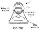
本発明の別の目的は、LEDベース照明サブシステムが照明の狭領域フィールドの目標物体を自動的に照明すると同時に、マルチ-モード画像形成及び検出(IFD)サブシステムがその中の位置合せされた1Dバーコード・シンボルの狭領域画像をキャプチャし、かつトリガ・スイッチによって広領域照明及び画像キャプチャ・モードに手動で切り替えられた場合に、LEDベース照明サブシステムが照明の広領域フィールドの目標物体を照明すると同時に、マルチ-モードIFDサブシステムがその上にランダムに配向された1Dまたは2Dコード・シンボルの広領域画像をキャプチャする、ハンド-サポータブル半自動デジタル・イメージング・ベース・バーコード読取りシステムを提供することにある。 Another object of the present invention is that the LED-based illumination subsystem automatically illuminates a target object in a narrow field of illumination while the multi-mode imaging and detection (IFD) subsystem is aligned therein. When a narrow area image of a 1D barcode symbol is captured and manually switched to wide area illumination and image capture mode by a trigger switch, the LED-based illumination subsystem will target the target object in the wide area field of illumination. Provides a hand-sportable semi-automatic digital imaging-based bar code reading system that simultaneously captures a wide-area image of 1D or 2D code symbols randomly oriented on it, with a multi-mode IFD subsystem There is to do.
本発明の別の目的は、狭領域画像キャプチャ・モード中に目標物体に照準を定めかつ位置合せされた1Dバーコード・シンボルを照明するために狭領域照明と、広領域画像キャプチャ・モード中にランダムに配向された1Dまたは2Dバーコード・シンボルの広領域画像を照明するために広領域照明とをイネーブルするマルチ-モード照明サブシステムを採用している、ハンド-サポータブル・イメージング・ベース・バーコード・シンボル読取り装置を提供することにある。 Another object of the present invention is to provide a narrow area illumination and a wide area image capture mode to illuminate a 1D barcode symbol aimed at and aligned with the target object during the narrow area image capture mode. Hand-supportable imaging base bar employing a multi-mode illumination subsystem that enables wide area illumination to illuminate a wide area image of randomly oriented 1D or 2D barcode symbols To provide a code symbol reader.
本発明の別の目的は、バーコード・シンボル・イメージング動作中に近視野及び遠視野広領域照明の生成を制御するために自動物体存在及び範囲検出を採用している、ハンド-サポータブル・イメージング・ベース・バーコード・シンボル読取り装置を提供することにある。 Another object of the present invention is hand-supportable imaging that employs automatic object presence and range detection to control the generation of near-field and far-field wide-area illumination during barcode symbol imaging operations. To provide a base bar code symbol reader.
本発明の別の目的は、汎用露光技法(global exposure technique)を用いているCMOS形画像センサを採用している、ハンド-サポータブル・イメージング・ベース・バーコード・シンボル読取り装置を提供することにある。 Another object of the present invention is to provide a hand-supportable imaging-based bar code symbol reader employing a CMOS image sensor using a global exposure technique. is there.
本発明の別の目的は、そのハンド-サポータブル筐体内に組み込まれた帯域通過光学フィルタ・サブシステムを有するCMOS形画像感知アレイを採用している、ハンド-サポータブル・イメージング・ベース・バーコード・シンボル読取り装置を提供することにある。 Another object of the present invention is a hand-supportable imaging-based barcode employing a CMOS image sensing array having a bandpass optical filter subsystem incorporated within the hand-supportable housing. • To provide a symbol reader.
本発明の別の目的は、リアルタイム画像分析に応じて動的に再構成可能である動作の複数のモードを有しているマルチ-モード画像処理バーコード・シンボル読取りサブシステムを採用している、ハンド-サポータブル・イメージング・ベース自動識別1D/2Dバーコード・シンボル読取り装置を提供することにある。 Another object of the present invention employs a multi-mode image processing barcode symbol reading subsystem having multiple modes of operation that are dynamically reconfigurable in response to real-time image analysis. It is to provide a hand-supportable imaging-based automatic identification 1D / 2D barcode symbol reader.
本発明の別の目的は、照明及びイメージング動作中にマルチ-モード画像形成及び検出サブシステムによって検出された物体が十分に照明されかつ検出された物体の高品質デジタル画像が形成されかつ検出されるようなLEDベース・マルチ-モード照明サブシステムの動作を自動的に制御する自動照明及び露光制御サブシステムを採用している、ハンド-サポータブル・イメージング・ベース・バーコード・シンボル読取り装置を提供することにある。 Another object of the present invention is that the objects detected by the multi-mode imaging and detection subsystem are fully illuminated during illumination and imaging operations and a high quality digital image of the detected objects is formed and detected. A hand-supportable imaging-based bar code symbol reader employing an automatic illumination and exposure control subsystem that automatically controls the operation of such LED-based multi-mode illumination subsystems There is.
本発明の別の目的は、3モードLEDベース照明サブシステムを採用している、ハンド-サポータブル・イメージング・ベース・バーコード・シンボル読取り装置を提供することにある。 Another object of the present invention is to provide a hand-supportable imaging based bar code symbol reader employing a three mode LED based illumination subsystem.
本発明の別の目的は、モジュラ画像処理アーキテクチャを有するマルチ-モード画像処理ベース・バーコード読取りサブシステムを採用している、ハンド-サポータブル・イメージング・ベース・バーコード・シンボル読取り装置を提供することにある。 Another object of the present invention is to provide a hand-supportable imaging-based bar code symbol reader employing a multi-mode image processing based bar code reading subsystem having a modular image processing architecture. There is.
本発明の別の目的は、動作の狭領域及び広領域画像キャプチャ・モードを有している半自動ハンド-サポータブル・イメージング・ベース・バーコード・シンボル読取り装置における1D/2Dバーコード・シンボロジーの自動識別を実行する方法を提供することにある。 Another object of the present invention is to automate 1D / 2D barcode symbology in a semi-automatic hand-supportable imaging-based barcode symbol reader having narrow and wide area image capture modes of operation. It is to provide a method for performing identification.
本発明の別の目的は、そこに図式的に表された1D/2Dバーコード・シンボルを読取るように半自動ハンド-サポータブル・イメージング・ベース・バーコード・シンボル読取り装置内で物体のキャプチャされたデジタル画像を処理する方法及び装置を提供することにある。 Another object of the present invention is to capture an object in a semi-automatic hand-supportable imaging-based bar code symbol reader to read the 1D / 2D bar code symbol schematically represented therein. It is to provide a method and apparatus for processing a digital image.
本発明の別の目的は、その中心から参照される物体のキャプチャされたデジタル画像に螺旋的掃引特徴抽出分析を採用している、ハンド-サポータブル・イメージング・ベース・バーコード・シンボル読取り装置を提供することにある。 Another object of the present invention is a hand-supportable imaging-based bar code symbol reader that employs spiral sweep feature extraction analysis on a captured digital image of an object referenced from its center. It is to provide.
本発明の別の目的は、1Dバーコード・シンボルを担持している物体のキャプチャされた狭領域デジタル画像の中心から参照された外方向に配向された方法で適用される簡単な復号画像処理動作を採用している画像処理ベース・バーコード読取りサブシステムを有している、自動ハンド-サポータブル・イメージング・ベース・バーコード・シンボル読取り装置を提供することにある。 Another object of the present invention is a simple decoded image processing operation applied in an outwardly oriented manner referenced from the center of a captured narrow area digital image of an object carrying a 1D barcode symbol. It is an object of the present invention to provide an automatic hand-supportable imaging-based bar code symbol reader having an image processing based bar code reading subsystem that employs the above.
本発明の別の目的は、自動物体存在及び範囲検出サブシステムによって生成される制御起動信号に応答する自動露光測定及び照明制御サブシステムによって駆動される遠視野及び近視野LED照明アレイを有するLEDベース・マルチ-モード照明サブシステムを採用しているデジタル・イメージング・ベース・バーコード・シンボル読取りシステムを提供することにある。 Another object of the present invention is an LED base having a far field and near field LED illumination array driven by an automatic exposure measurement and illumination control subsystem in response to a control activation signal generated by an automatic object presence and range detection subsystem. It is to provide a digital imaging based bar code symbol reading system employing a multi-mode illumination subsystem.
本発明の別の目的は、物体照明及び画像キャプチャ動作中に領域型画像感知アレイ及び自動物体存在検出サブシステムによって生成される制御起動信号に応答する自動露光測定及び制御サブシステムによって駆動されるLEDベース照明サブシステムを採用しているデジタル・イメージング・ベース・バーコード・シンボル読取りシステムを提供することにある。 Another object of the present invention is an LED driven by an automatic exposure measurement and control subsystem in response to a control activation signal generated by the area-based image sensing array and the automatic object presence detection subsystem during object illumination and image capture operations. It is an object of the present invention to provide a digital imaging base bar code symbol reading system employing a base illumination subsystem.
本発明の別の目的は、CMOS画像感知アレイの画素の実質的に全ての行が集積の状態にあるときにだけ自動的に検出された物体を狭帯域LEDベース照明のフィールドに露光し、それにより前記バーコード・シンボル読取り装置と物体との間の相対運動に係わりなく高品質デジタル画像をキャプチャするためにLED照明駆動装置回路を制御する自動露光測定及び照明制御サブシステムを採用しているハンド-サポータブル・イメージング・ベース・バーコード・シンボル読取り装置を提供することにある。 Another object of the present invention is to expose an automatically detected object to a field of narrowband LED-based illumination only when substantially all rows of pixels of a CMOS image sensing array are in an integrated state, Hands employing an automatic exposure measurement and illumination control subsystem to control LED illumination driver circuitry to capture high quality digital images regardless of relative movement between the bar code symbol reader and the object -To provide a portable imaging-based bar code symbol reader.
本発明の別の目的は、CMOS画像感知アレイがLEDベース照明アレイからの狭帯域照明に露光される時間分が、システムに搭載された前記LEDベース照明アレイがCMOS画像感知アレイ及び自動物体存在検出サブシステムによって生成された制御起動信号に応じて狭帯域照明を生成する時間を制御することによって管理される、デジタル・イメージング・ベース・バーコード読取りシステムを提供することにある。 Another object of the present invention is that the amount of time that the CMOS image sensing array is exposed to narrowband illumination from the LED-based illumination array is such that the LED-based illumination array mounted in the system is CMOS image sensing array and automatic object presence detection It is an object of the present invention to provide a digital imaging based barcode reading system that is managed by controlling the time to generate narrowband illumination in response to a control activation signal generated by a subsystem.
本発明の別の目的は、バーコード・シンボルを含んでいるキャプチャされたデジタル画像における興味領域(roi)の最大画素高さに比例する画素-オフセット距離の数によって離間された一組の並列仮想走査線に沿ってキャプチャされたデジタル画像を自動的に処理するサブシステムを有しているハンド-サポータブル・デジタル・イメージング・ベース・バーコード・シンボル読取りシステムを提供することにある。 Another object of the present invention is a set of parallel virtuals separated by a number of pixel-offset distances proportional to the maximum pixel height of the region of interest (roi) in the captured digital image containing barcode symbols. It is an object of the present invention to provide a hand-supportable digital imaging-based bar code symbol reading system having a subsystem for automatically processing digital images captured along a scan line.
本発明の別の目的は、単一のバーコード・シンボル読取りサイクル中にその読取りのモードを切り替え、かつ各前記読取りのモード内で、異なる画像処理ベース・バーコード・シンボル読取り方法を自動的に適用する、マルチ-モード画像処理シンボル読取りサブシステム採用しているデジタル・イメージング・ベース・バーコード・シンボル読取りシステムを提供することにある。 Another object of the present invention is to switch the mode of reading during a single bar code symbol reading cycle and automatically implement different image processing based bar code symbol reading methods within each said mode of reading. To provide a digital imaging-based bar code symbol reading system employing a multi-mode image processing symbol reading subsystem.
本発明の別の目的は、イメージング・ベース・バーコード・シンボル読取り装置における復号解画像度の下限を決定する方法及びシステムを提供することにある。 Another object of the present invention is to provide a method and system for determining the lower limit of the decoded resolution in an imaging-based bar code symbol reader.
本発明の別の目的は、照明及びイメージング動作中に前記物体からの光の鏡面反射形の反射によってもたらされる雑音が実質的に存在しないそのデジタル画像を生成するように物体を知的に照明する方法を採用しているハンド-サポータブル・デジタル・イメージング・ベース・バーコード・シンボル読取りシステムを提供することにある。 Another object of the invention is to intelligently illuminate an object so as to produce its digital image substantially free of noise caused by specular reflections of light from the object during illumination and imaging operations. The object is to provide a hand-supportable digital imaging-based bar code symbol reading system employing the method.
本発明の別の目的は、多層モジュラ・ソフトウェア・プラットフォーム上で実現されるハンド-サポータブル半自動デジタル・イメージング・ベース・バーコード・シンボル読取りシステムを提供することにある。 It is another object of the present invention to provide a hand-supportable semi-automatic digital imaging based bar code symbol reading system implemented on a multi-layer modular software platform.
本発明の別の目的は、デジタル・イメージング・ベース・バーコード・シンボル駆動式ポータブル・データ端末システムを提供することにある。 It is another object of the present invention to provide a digital imaging based bar code symbol driven portable data terminal system.
本発明の別の目的は、各イメージング・サイクル中に、その中の実質的に画素の全ての行が集積(統合・組合せ)の状態でありかつ共通の集積時間を有する場合に画素データの単一のフレームがCMOS領域形画像感知アレイによって自動的に検出され、そして画素データが前記CMOS領域形画像感知アレイからFIFOバッファに伝送され、そしてそれに続く画像処理のためにメモリにマップされる、ハンド-サポータブル・デジタル・イメージング・ベース・バーコード読取りシステムを提供することにある。 Another object of the present invention is that during each imaging cycle, pixel data is simply processed when substantially all rows of pixels therein are in an integrated (integrated / combined) state and have a common integration time. A frame is automatically detected by the CMOS area image sensing array and pixel data is transferred from the CMOS area image sensing array to a FIFO buffer and mapped to memory for subsequent image processing. -To provide a portable digital imaging-based bar code reading system.
本発明の別の目的は、視野を有する画像感知アレイを有し、かつLEDベース照明サブシステムを有しているハンド-サポータブル・イメージャ内の自動照明制御の方法を提供することにあり、この方法は、キャプチャされた画像の空間強度を分析することを含むソフトウェア・ベース画像照明計測プログラムを採用する。 Another object of the present invention is to provide a method of automatic illumination control in a hand-supportable imager having an image sensing array having a field of view and having an LED-based illumination subsystem. The method employs a software-based image illumination measurement program that includes analyzing the spatial intensity of the captured image.
本発明の別の目的は、改善照明制御のために、自動露光測定及び照明制御サブシステムと、ソフトウェア・ベース画像照明計測プログラムとを備えている、ハンド-サポータブル・デジタル・イメージング・ベース・バーコード・シンボル読取り装置を提供することにある。 Another object of the present invention is a hand-supportable digital imaging base bar comprising an automatic exposure measurement and illumination control subsystem and a software based image illumination measurement program for improved illumination control. To provide a code symbol reader.
本発明の別の目的は、画像クロッピング・ゾーン(ICZ)フレーミング及びポスト画像キャプチャ・クロッピング処理を採用しているハンド-サポータブル・デジタル・イメージング・ベース・バーコード・シンボル読取りシステムを提供することにある。
本発明のこれら及びその他の目的は、この後で及びここに添付した特許請求の範囲において、より明白に理解されるようになるであろう。Another object of the present invention is to provide a hand-supportable digital imaging-based bar code symbol reading system that employs image cropping zone (ICZ) framing and post image capture cropping processing. is there.
These and other objects of the present invention will become more clearly understood hereinafter and in the claims appended hereto.
本発明の目的を実行する方法のより完全な理解のために、以下の実施形態の詳細な説明を以下に簡単に説明する添付図面と共に読むことができるであろう。 For a more complete understanding of the manner of carrying out the objects of the invention, the following detailed description of embodiments may be read in conjunction with the accompanying drawings, which are briefly described below.
同じ構成要素が同じ参照番号を用いて示される、添付図面の図を参照して、本発明のハンド-サポータブ・イメージング・ベース・バーコード・シンボル読取りシステムの様々な実施形態をより詳細に説明する。 Various embodiments of the hand-supported imaging-based bar code symbol reading system of the present invention will be described in more detail with reference to the figures of the accompanying drawings, wherein like components are indicated with like reference numerals. .
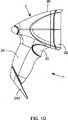
本発明の第1実施形態のハンド-サポータブル・デジタル・イメージング・ベース・バーコード読取りデバイス
図1A〜図1Kを参照して、実施形態では、図6A2に示された光透過特性を有している高域通過(赤色波長反射)光学フィルタ素子4Aを有する光透過窓3が設けられたハンドル部分2A及びヘッド部分2Bを有しているハンド-サポータブル筐体2を備えている、本発明の第1の実施形態のハンド-サポータブル・デジタル・イメージング・ベース・バーコード・シンボル読取りデバイス1を詳細に示す。以後、詳細に記述されるように、高域通過光フィルタ素子4Aは、高域通過光フィルタ素子4Aと協力する、図6A1に特性が示された内側に取り付けられた低域通過光フィルタ素子4B内で協力する。これらの高域及び低域通過フィルタ素子4A及び4Bは、筐体のヘッド部分に組込みかつイメージング動作中に照明の狭帯域(例えば、633ナノメートル)だけを筐体から出し入れさせる狭帯域光フィルタ・システム4を供給するように協力する。Hand- SportableDigital Imaging Base Barcode Reading Device of First Embodiment of the Invention Referring to FIGS. 1A-1K, the embodiment has the light transmission characteristics shown in FIG. 6A2. Of the present invention, comprising a
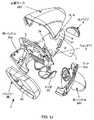
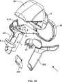
図1I、1J、及び1Kに最もよく示されているように、本実施形態のハンド-サポータブル筐体2は、左右筐体ハンドル半分2A1及び2A2;ハンドル半分2A1と2A2との間に取り付けられる脚状構造体2A3;筐体半分に設けられた一対の離間された開口2D1及び2D2内でスナップ・フィット(スナップ式に嵌合)しかつ一対の離間された開口2D1及び2D2内で枢動するトリガ・スイッチ構造体2C;それを通って光透過窓3が形成されかつそれらが接合される場合にハンドル半分2A1及び2A2によって形成された凹部内で支持され、かつシステムによって供給された全てのLED照明アレイを支持する光透過窓パネル5;電子光学構成要素を支持し、かつハンドル筐体半分内に取り付けられた直交して取り付けられたPCボード7に動作可能に接続される光学ベンチ6;発光ダイオード(LEDs)9のアレイの上に取り付けるための光パイプ・レンズ素子8及びハンド-サポータブル筐体のヘッド部分の後部内に取り付けられた光パイプ構造体10;及び、トップ筐体部分2B1及び左右ハンドル半分2A1及び2A2とその間に挟まれた光透過窓パネル5とを一緒に保持すると同時に、それに対するショック保護のレベルを供給するフロント・バンパー構造体2Eを備えている。 As best shown in FIGS. 1I, 1J, and 1K, the hand-
図27〜図33に示された本発明の他の実施形態では、ハンド-サポータブル筐体のフォーム・ファクタ(構造因子)は、異なりうる。更に別のアプリケーションでは、筐体がハンド-サポータブルである必要はないが、しかし、デスクトップまたはカウンタートップ表面上の固定支持のために、または商業的または工業的な応用での使用のために設計されうる。 In other embodiments of the present invention illustrated in FIGS. 27-33, the form factor of the hand-supportable enclosure may vary. In yet another application, the enclosure need not be hand-supportable, but designed for fixed support on a desktop or countertop surface, or for use in commercial or industrial applications Can be done.
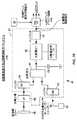
本発明のハンド-サポータブル・デジタル・イメージ・ベース・バーコード読取りデバイス用のシステム設計モデルとしての略ブロック機能図
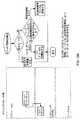
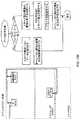
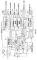
図2A1のシステム設計モデルに示されているように、実施形態のハンド-サポータブ・デジタル・イメージング・ベース・バーコード・シンボル読取りデバイス1は、図示するように、IRベース物体存在及び範囲検出サブシステム12;画像キャプチャの狭領域モード、画像キャプチャの近視野広領域モード、及び画像キャプチャの遠視野広領域モードを有しているマルチ-モード領域型画像形成及び検出(即ち、カメラ)サブシステム13;照明の狭領域モード、照明の近視野広領域モード、及び照明の遠視野広領域モードを有しているマルチ-モードLEDベース照明サブシステム14;自動露光測定及び照明制御サブシステム15;画像キャプチャリング及びバッファリング・サブシステム16;図2A2に示しかつ上記に詳述した画像処理ベース・バーコード・シンボル読取りの5つのモードを有しているマルチ-モード画像処理バーコード・シンボル読取りサブシステム17;入出力サブシステム18;ユーザ開始制御起動信号をデバイスに送るための手動起動可能トリガ・スイッチ2C;システム・モード構成パラメータ・テーブル(表)70;及び上述したサブシステムの各々と組み込まれたシステム制御サブシステム18を備えている。Schematic Block Functional Diagram as System Design Model for Hand-Sustainable Digital Image-Based Barcode Reading Device of the Present Invention As shown in the system design model ofFIG . The digital imaging based bar code
IRベース物体存在及び範囲検出サブシステム12の主な機能は、マルチ-モード画像形成及び検出サブシステム13のFOV内でIRベース物体検出フィールド20を自動的に生成し、物体検出フィールド(20A,20B)の所定領域内で物体の存在を検出し、かつ物体がシステムの物体検出フィールド内で検出される時間及び場所を示すためにシステム制御サブシステム19に供給される制御起動信号A1を生成することである。 The main function of the IR-based object presence and
第1の実施形態では、マルチ-モード画像形成及び検出(即ち、カメラ)サブシステム13は、その上に物体が画像形成される視野(FOV)23を生成するための画像形成(カメラ)光学系21と、照明及び画像収集/キャプチャ動作中に物体から反射された画像形成された光(投影光)を検出するためのCMOS領域画像感知アレイ22とを有している。 In the first embodiment, the multi-mode imaging and detection (ie, camera)
第1の実施形態では、マルチ-モードLEDベース照明サブシステム14の主な機能は、各々が狭光学帯域幅を有しかつそれぞれイメージングの狭領域及び広領域モード中にマルチ-モード画像形成及び検出サブシステム13のFOV内に制限された、狭領域照明フィールド24、近視野広領域照明フィールド25、及び遠視野広領域照明フィールド26を生成することである。この構成は、マルチ-モード照明サブシステム14から透過されかつ照明された物体から反射された光だけが、(1)パネル5の直前の光透過開口3に取り付けられた高域通過(即ち、赤色波長反射)フィルタ素子4A、及び(2)図3Cに示すように画像感知アレイ22の前またはパネル5の後のどこかに取り付けられた低域通過フィルタ素子4Bによって実現された狭帯域透過種類光学フィルタ・サブシステム4を通って最終的に透過されることを確実にするために設計されている。図6A4は、マルチ-モード照明サブシステム14で採用されたLED照明アレイからの放射のスペクトル特性に対して曲線で描いた、狭帯域透過スペクトル・フィルタ・サブシステム4の結果として得られた複合透過特性を示している。 In the first embodiment, the main function of the multi-mode LED-based
狭帯域組込み光フィルタ・サブシステム4の主な機能は、CMOS画像感知アレイ22が、マルチ-モード照明サブシステム14に関連付けられたLED駆動装置回路30によって駆動される3組のLEDベース照明アレイ27、28及び29によって透過された狭帯域可視照明だけを受信する一方で、光収集光学系によって収集された周囲光の全ての他の構成要素が画像感知アレイ22で実質的に拒否されることを確実にすることであり、それによりそこにおいて改善されたSNRを供給し、それゆえにシステムの性能を改善する。 The main function of the narrowband embedded
自動露光測定及び照明制御サブシステム15の主な機能は、2つの要素からなる:(1)その画像感知アレイ22の回りでシステムの光学系によって収集された光エネルギー(即ち、光)のパワー密度[ジュール/センチメートル(joules/cm)]をリアルタイムで測定し、かつ良好な画像形成及び検出に必要な露光量を示している自動露光制御信号を生成すること;及び(2)システム制御サブシステム19によって供給される照明アレイ選択制御信号と組み合せて、マルチ-モード照明サブシステムの選択したLEDアレイ27、28及び/又は29の出力パワーを自動的に駆動しかつ制御して、システムのFOV内の物体がLEDベース照明に最適に露光されかつ最適画像が画像感知アレイ22で形成されかつ検出されることである。 The main function of the automatic exposure measurement and
画像キャプチャリング及びバッファリング・サブシステム16の主な機能は、(1)システムの画像形成光学系21によって2D画像感知アレイ22に集束された2-D画像全体を検出すること、(2)キャプチャされた画像フレームの選択した興味領域に対してか、または検出した画像全体に対してデジタル画素データ31のフレームを生成すること、そして(3)それがキャプチャされたときに画像データの各フレームをバッファすることである。とりわけ、実施形態において、単一の2D画像フレーム(31)は、各画像キャプチャ及び処理サイクル中、または処理サイクルの特定のステージ中に、キャプチャされ、画像フレーム重ね書き、および画像キャプチャ及び復号処理の同期化に関連付けられた、Welch Allynに付与されかつここに参考として採用された、米国特許第5,932,862号及び5,942,741号において取り組まれたような、問題を排除する。 The main functions of the image capturing and
マルチ-モード・イメージング・バーコード・シンボル読取りサブシステム17の主な機能は、システム動作の両方の狭領域及び広領域照明モード中に、画像キャプチャリング及びバッファリング・サブシステム16によってキャプチャされかつバッファされた画像を処理することである。係る画像処理動作は、図14〜図25に例示され、かつこの後に詳細が記述される、画像ベース・バーコード復号方法を含む。 The main function of the multi-mode imaging bar code
入出力サブシステム18の主な機能は、外部ホスト・システム及びデバイスとの標準及び/又は専用の通信インターフェイスをサポートし、かつ処理した画像データ、等を係るインターフェイスにより係る外部ホスト・システムまたはデバイスに出力することである。係るインターフェイスの例、及びインターフェイスを実現するための技術は、その全体が参考文献としてここに採り入れられる米国特許第6,619,549号に記載れている。 The main function of the input / output subsystem 18 is to support a standard and / or dedicated communication interface with an external host system and device, and to process the processed image data, etc. with the external host system or device. Is to output. Examples of such interfaces and techniques for implementing the interfaces are described in US Pat. No. 6,619,549, which is hereby incorporated by reference in its entirety.
システム制御サブシステム19の主な機能は、図示するように、制御または管理シグナリング・サービスを組み込まれた各サブシステム構成要素に供給することである。このサブシステムは、実施形態において、プログラムされたマイクロプロセッサによって実現することができると同時に、図2Bに示され、かつ図11A〜13Lに表され、そしてこの後で詳細に記述される、コンピューティング・プラットフォーム上でサポートされる3層ソフトウェア・アーキテクチャによって実現される。 The main function of the
ハンド-サポータブル筐体に組み込まれた手動起動可能トリガ・スイッチ2Cの主な機能は、トリガ・スイッチ2Cを手動で押し下げることによりユーザが制御起動信号を生成することができ、かつ、ここに詳細に説明する、この制御起動信号をその複雑なシステム及びサブシステム制御動作を実行することに使用するシステム制御サブシステム19に供給することである。 The main function of the manually
システム・モード構成パラメータ・テーブル70の主な機能は、図26A〜26Cに示され、かつその複雑な動作中に要求されるようにシステム制御サブシステム19によって読取りかつ用いることができる、動作テーブルのプログラマブル・モードで特定されたシステム動作の利用可能なプログラマブル・モードの各々に対する一組の構成パラメータを(不揮発性/永続性メモリに)記憶することである。
各サブシステムの詳細な構造及び機能は、上記のように詳細にここに記述されるであろう。The main function of the system mode configuration parameter table 70 is the operation table shown in FIGS. 26A-26C and can be read and used by the
The detailed structure and function of each subsystem will now be described in detail as described above.
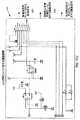
本発明のハンド-サポータブル・デジタル・イメージ・ベース・バーコード読取りデバイス用のシステム実施(開発)モデルとしての略図
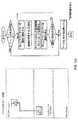
図2Bは、図1A〜図1Lに示したハンド-サポータブル・デジタル・イメージ・ベース・バーコード読取りデバイス1に対するシステム実施の略図を示す。このシステム実施に示すように、バーコード・シンボル読取りデバイスは、
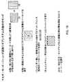
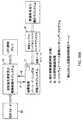
LEDベース・マルチ-モード照明サブシステム14及び自動露光測定及び照明制御サブシステム15によって実行される電子機能を実現しているコンポーネント(構成要素)を担持している照明ボード33;ランダム的にアクセス可能な興味領域(ROI)ウィンドウ機能を有する1280*1024解画像度で7フレーム/秒で、25Mhzマスタ・クロックで実行される高解画像度(1280×1024 8ビット 6マイクロン画素サイズ)CMOS画像感知アレイ22を担持し、マルチ-モード画像形成及び検出サブシステム13によって実行される電子機能を実現しているCMOSカメラ・ボード34;(i)16ビット 100Mhz外部バス・スピードを有する200mHz 1.0コア電圧で実行されるインテル・サビナール(Intel Sabinal)32ビットマイクロプロセッサPXA210 36、(ii)拡張可能(例えば、8+メガバイト)インテルJ3非同期16ビット・フラッシュ・メモリ37、(iii)100MHzの16メガバイトSDRAM38、(iv)50Mhzクロック周波数及び60MB/秒 データ速度で実行され、カメラ・タイミングを制御しかつ画像収集処理を駆動するように構成された、ザイリンクス・スパルタン(Xilinx Spartan)II FPGA FIFO39、(v)システムの他方のサブシステムを実現するための、マルチメディア・カード・ソケット40、(vi)I2Cバスによって調整可能なMCU用パワー管理モジュール41、及び(vii)一対のUARTs42A及び42B(一つがIRDAポート用、そして一つがJTAGポート用)、を含んでいるCPUボード35(即ち、コンピューティング・プラットフォーム);I/Oサブシステム18によって実行される機能を実現するためのインターフェイス・ボード43;及びサブシステム12を実現するためのIRベース物体存在及び範囲検出回路44、を備えている多数のハードウェア・コンポーネント(構成要素)を用いて実現される。FIG. 2B isa schematic diagramof a system implementation (development) model for the hand-sportable digital image-based barcode reading device of the present invention . FIG. 2B illustrates the hand-sportable digital image image shown in FIGS. 1 shows a schematic diagram of a system implementation for a base
Illumination board 33 carrying components that implement the electronic functions performed by the LED-based multi-mode illumination subsystem 14 and the automatic exposure measurement and illumination control subsystem 15; randomly accessible High resolution (1280 × 1024 8-bit 6-micron pixel size) CMOS image sensing array with a 1280 * 1024 resolution at 7 frames / second and a 25 Mhz master clock with a large region of interest (ROI) window function CMOS camera board 34 carrying 22 and implementing the electronic functions performed by the multi-mode imaging and detection subsystem 13; (i) 200 mHz 1.0 core voltage with 16-bit 100 Mhz external bus speed Intel Sabinal (Intel S abinal) 32-bit microprocessor PXA210 36, (ii) expandable (eg, 8+ megabytes) Intel J3 asynchronous 16-bit flash memory 37, (iii) 100 MHz 16 megabyte SDRAM 38, (iv) 50 Mhz clock frequency and 60 MB / s Xilinx Spartan II FPGA FIFO 39, (v) for implementing the other subsystem of the system, configured to run at data rate, control camera timing and drive image acquisition process Multimedia card socket 40, (vi) MCU power management module 41 adjustable by I2C bus, and (vii) a pair of UARTs 42A and 42B (one for the IRDA port and one for the JTAG port), Including a CPU board 35 (ie, a computing platform); an interface board 43 for implementing functions performed by the I / O subsystem 18; and an IR-based object presence for implementing the subsystem 12 and This is realized by using a number of hardware components (components) including the range detection circuit 44.
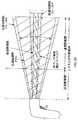
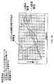
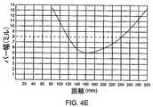
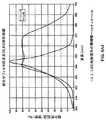
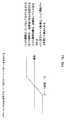
実施形態では、バーコード読取り装置によってサポートされる画像形成光学系21は、ターゲット(目標)への公称焦点距離で103mm(ミリメートル)の視野を供給する。光学系のパラメータの予備テストを図4Bに示す(図4B上の距離は、エッジから概ね80mmのバーコード・シンボル読取り装置の内側に配置される、画像感知アレイ22の位置から与えられる)。図4Cに示すように、画像形成光学系の被写界深度(depth of field)は、狭いモジュール毎に5ミル(mils)の解画像度を有するバーコードに対して概ね69mmから、狭いモジュール毎に13ミル(mils)の解画像度を有するバーコードに対して181mmまで変化する。 In an embodiment, the
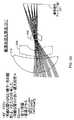
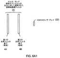
マルチ-モード照明サブシステム14は、イメージング・ウィンドウから短い距離及び長い距離の両方に配置されたバーコードの高コントラスト画像を生成するために十分な照明によりバーコード・シンボル読取り装置の光学的視野(FOV)23に及ぶように設計されている。また、照明サブシステムは、二つの目的:(a)読取り装置の光学的ビューの場所をユーザに示すこと;及び(b)画像のちょっと数ラインの素早いスキャンを可能にしかつバーコードが適切に位置合せされるならば超高速バーコード復号を試みること、を有している狭領域(薄い高さ)ターゲッティング・ビーム24も供給する。バーコードが復号するために一直線上に照明された画像に対して整合されていないならば、視野全体が、広領域照明フィールド25または26により照明され、かつ視野全体の画像は、画像キャプチャ及びバッファリング・サブシステム16によって収集され、かつその配向に関わりなくその中に存在するバーコード・シンボルの読取りを確実にするためにマルチ-モード・バーコード・シンボル読取りサブシステム17によって処理される。 The
バーコード・シンボル読取り装置内に採用されたインターフェイス・ボード43は、外部の世界と通信するためにバーコード・シンボル読取り装置に対するハードウェア通信インターフェイスを供給する。システムで実施されるインターフェイスは、RS232、キーボード・ウェッジ、及び/又はUSB、または上記の組合せ、並び手元にある特定のアプリケーションにより必要または要求されるその他のものを典型的に含む。 An
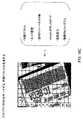
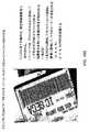
狭帯域照明の狭領域及び広領域フィールドによってそれぞれ支援された、イメージングのその狭領域(線形)及び広領域モード中の領域型画像形成及び検出(即ち、カメラ)サブシステムの明細書
図3B〜図3Eに示すように、マルチ-モード画像形成及び検出(IFD)サブシステム13は、動作の狭領域画像キャプチャ・モード(即ち、画像感知アレイの中心の回りの画素のいくつかの中央の行だけがイネーブルされる)及び広領域画像キャプチャ・モード(即ち、画像感知アレイの全ての画素がイネーブルされる)を有する。画像形成及び検出サブシステム13のCMOS画像感知アレイ22は、照明されかつ画像形成される物体上の視野(FOV)23を画像感知アレイに設置する画像形成光学系21を有する。図示するように、このFOVは、バーコード読取り装置内に組み込まれたマルチ-モード照明サブシステム14によって照明される。3B-Bspecification of the area-based imaging and detection (i.e. camera) subsystem during its narrow-area (linear) and wide-area modes of imaging, assisted by the narrow-area and wide-area fields of narrow-band illumination, respectively . As shown in 3E, the multi-mode imaging and detection (IFD)
マルチ-モード照明サブシステム14は、光透過ウィンドウ・パネル5に取り付けられ、かつ光透過ウィンドウ4Aの回りに配列された3つの異なるLED-ベース照明アレイ27,28及び29を含む。各照明アレイは、動作の異なるモード中にバーコード読取り装置のFOVの異なる部分を照明するように設計されている。マルチ-モード照明サブシステム14の狭領域(線形)照明モード中に、23で示されたFOVの中央狭-広部分は、図3Aに示した、狭領域照明アレイ27によって照明される。FOVの近視野部分内で物体を検出するIR物体存在及び範囲検出サブシステム12に応じて起動される、マルチ-モード照明サブシステム14の近視野広領域照明モード中に、FOVの近視野広領域部分は、図3Aに示した、近視野広領域照明アレイ28によって照明される。FOVの遠視野部分内で物体を検出するIR物体存在及び範囲検出サブシステム12に応じて起動される、マルチ-モード照明サブシステム14の遠視野広領域照明中に、FOVの遠視野広領域部分は、図3Aに示した、遠視野広領域照明アレイ29によって照明される。図3Aでは、狭帯域照明のこれらのフィールド(視野)と画像形成及び検出サブシステム13のFOVの遠及び近視野部分と間の空間関係が示されている。 The
図3Bには、マルチ-モードLEDベース照明サブシステム14が示されており、図3Cに示されかつハンド-サポータブル・デジタル・イメージング-ベース・バーコード・シンボル読取り装置内に組み込まれた、その狭帯域透過型光フィルタ・サブシステム4を通して可視狭帯域照明を透過している。マルチ-モード照明サブシステム14からの狭帯域照明は、画像形成及び検出サブシステム13の画像形成光学系のFOVを有する物体を照明し、かつそれから反射されかつ散乱された光線は、高域通過及び低域通過光学フィルタ4A及び4Bを通して透過され、そしてその上に集束された検出画像の形成のために最終的に画像感知アレイ22上に集束されると同時に、周囲光の他の構成要素は、画像感知アレイ22における画像検出に到達する前に実質的に拒否される。とりわけ、実施形態では、赤色波長反射高域通過光学フィルタ素子4Aは、画像形成光学系21の前のデバイスのイメージング・ウィンドウに配置される一方で、低域通過光学フィルタ素子4Bは、画像形成光学系21の集束レンズ素子間で画像感知アレイ22の前に配置される。これは、FOV内の物体が、サブシステム14から生成された照明の狭帯域内のスペクトル成分だけを用いて画像感知アレイ22で画像形成されることを確実にするためにバーコード読取り装置内に組み込まれる狭帯域光学フィルタ・サブシステム4を形成すると同時に、この狭い領域(例えば、15nm)の外側の周囲光の全ての他の構成要素を実質的に拒否する。 In FIG. 3B, a multi-mode LED-based
図3Dに示すように、ハンド-サポータブル・デジタル・イメージ-ベース・バーコード読取り装置内に採用された画像形成及び検出サブシステム14は、それぞれが可能な限り小さく作られ(12mmの最大直径を有し)、球面を有し、かつ一般的なガラス、例えば、LAK2(〜LaK9)、ZF10(=SF8)、LAF2(〜LaF3)で作られた、3つのレンズ21A,21B及び21Cを備えている。集合的に、これらのレンズは、図3Eに示すように、レンズ保持アセンブリ45内に一緒に保持され、かつバーコード読取り装置のCMOS画像感知アレイ22の光軸に沿って配列された画像形成サブシステムを形成する。 As shown in FIG. 3D, the imaging and
図3Eに示すように、レンズ保持アセンブリ45は、レンズ素子21A、21B及び21Cを保持するためのバレル構造体45A1、45A2;及び画像感知アレイ22を保持するためのベース構造体45Bを備え;アセンブリは、製造中に固定焦点レンズ・アセンブリの焦点を合わせるためにバレス構造体45Aがベース構造体45B内で摺動するように構成されている。 As shown in FIG. 3E, the
図3F1及び図3F2において、レンズ保持アセンブリ45は、イメージング・センサ・アレイ22は、システムの中心軸に沿って定義された光学経路(光路)に沿って取り付けられる。実施形態では、画像感知アレイは、例えば、ランダム的にアクセス可能な興味領域(ROI)ウィンドウ機能を有する、1280×1024画素解画像度(1/2"フォーマット)、6マイクロン画素サイズを有している。しかしながら、本発明の範囲または精神から逸脱することなく、ここに開示された本発明の原理を実施するために多くの他の種類のイメージング感知デバイス(例えば、CCD)を用いることができるということが理解される。 In FIGS. 3F1 and 3F2, the
変調伝達関数(MTF)を用いて本発明の画像ベース・バーコード読取り装置内の画像形成(即ち、カメラ)光学系を設計する方法
画像形成及び検出サブシステム13の画像形成(即ち、カメラ)光学系の機能は、画像感知アレイ22上に形成される物体の画像を、可能な限り正確的に、形成しかつ投影することである。画像の品質が様々な影響によって制限されるので、実際には、情報の損失なしで物体の絶対的に完全な画像再生を得ることは不可能である。これらの影響は、(i)回折、最良のレンズでさえも常に存在する;(ii)収差、存在するならば、一般的に、最小化されるだけで、消去されない;(iii)物体までの距離の変化、特にレンズがその焦点を動的に調整できないならば;等を含む。レンズ・アアセンブリを生成するために時間及びお金を費やす前に、本発明のバーコード・シンボル読取り装置に対する所与のレンズ設計は、アプリケーションの必要事項を満たすために十分によく動作するということを決定する必要がある。そこで、(i)レンズ性能を定量化するために一つ以上の設計基準を設定すること、及び(ii)所望の性能が達成されるまでこれらの基準の周りの設計を最適化することは、非常に有用である。Method for Designing Imaging (i.e. Camera) Optics in the Image-Based Barcode Reader of the Present Invention Using Modulation Transfer Function (MTF) Imaging and
そのシステムにおける画像形成光学系を設計するための好適な基準は、変調伝達関数、またはMTFである。MTFは、物体または画像に存在するコントラストの大きさ(程度)を与える。質的に、コントラストは、物体または画像における明るい領域と暗い領域との間の差と考えられうる。物体または画像の二つの領域の間の“輝度”における差が大きい程、以下の図に示すように、コントラストが大きく、図40Aに示すように、コントラストは、左から右に増大する。画像を考えて、画像センサからデータを与えると、定量的処理が可能である。一般的な8ビット・スケールでは、完全に黒である画素は、値0が割り当てられ、完全に飽和した白である画素は、値255が割り当てられる。従って、図40Bに示すように見える画像は、また、図40Cに示すように、その画素値のプロット(グラフ)によっても表されうる。これが目標物体の表示であるならば、結果として得られる画像は異なる。具体的には、上述した様々な影響により、コントラストは、厳密には保存されない。換言すると、物体特徴の間隔が近ければ、物体の画像におけるそのコントラストの再生が悪くなる。従って、物体の画像が図40Dに示したような図的表現のようなものに見えうるしかつ値のグラフは、図40Eに示す後に続く図的表現のようなものに見えうる。 A preferred criterion for designing the imaging optics in the system is the modulation transfer function, or MTF. The MTF gives the magnitude (degree) of contrast present in an object or image. Qualitatively, contrast can be thought of as the difference between light and dark areas in an object or image. The greater the difference in “luminance” between two regions of an object or image, the greater the contrast, as shown in the following figure, and the contrast increases from left to right as shown in FIG. 40A. Considering an image, given data from an image sensor, quantitative processing is possible. On a typical 8-bit scale, pixels that are completely black are assigned the
物体または画像に存在するコントラストの大きさを定量化するために数式が必要になり、そして光学系を通して画像形成された後のその変化は、評価されうる。有用なコントラスト量は、物体における所与の領域の変調Mとして定義することができ、以下のように与えられる: A mathematical formula is needed to quantify the magnitude of contrast present in the object or image, and its change after being imaged through the optical system can be evaluated. A useful amount of contrast can be defined as the modulation M of a given region in the object and is given as follows:

物体または画像におけるコントラストが大きい程、1の最大値までMの値が大きくなる。他方、物体または画像に何のコントラストもない(即ち、問題の物体の領域に識別可能な特徴がない)ことは、0の変調をもたらす。画像形成光学系が画像における目標物体の変調をどの程度保存するのかを決定するために、物体変調に対する画像変調の比、即ちMTFを形成することだけが必要である: The greater the contrast in the object or image, the greater the value of M up to a maximum value of 1. On the other hand, the absence of any contrast in the object or image (i.e. no distinguishable features in the area of the object in question) results in zero modulation. In order to determine how much the imaging optics preserves the modulation of the target object in the image, it is only necessary to form the ratio of image modulation to object modulation, ie MTF:
画像における物体コントラストの完全な再生(実際には不可能)は、1のMTFを結果としてもたらす。画像における物体コントラストの全損失は、0のMTFを与える。 Complete reproduction of object contrast in the image (which is not possible in practice) results in an MTF of 1. Total loss of object contrast in the image gives an MTF of zero.
ぶれ(blurring)と通常呼ばれる、画像の品質を劣化するあらゆる影響のインパクトを同時に考慮するので、MTFは、光学的設計における有用な概念である。先に説明したように、これらの影響は、回折、収差(球面、色、コマ、非点、画像面湾曲)及びその公称値からの物体距離の偏差を含む。しかしながら、MTFは、画像品質の単一の完全なまたはあらゆるものを含む量ではないということを完全性のために示しておくべきである。一つの潜在的な欠点は、MTFを検査することが同時に全ての影響の総合インパクトだけを明らかにし、かつ一つの欠陥または別の欠陥によってもたらされるぶれ(blurring)の間を識別することができないということである。どの影響がMTFを劣化し、かつそれぞれに対してどの程度までかを決定することが必要であるならば、他の方法を用いなければならないし、かつ他の基準を検査しなければならない。更に、MTFによってまったく明らかにされない、例えば、収差のような、潜在的な負の画像特性が存在する。光学設計者が気を付けないならば、得られることが可能であるように良好である、回折限界に近いMTFを有する画像は、あまりにも悪いので間近のアプリケーションで使用不能であるような収差を有しうることが可能である。 MTF is a useful concept in optical design because it simultaneously considers the impact of all the effects that degrade image quality, commonly referred to as blurring. As explained earlier, these effects include diffraction, aberration (spherical, color, coma, astigmatism, field curvature) and deviation of the object distance from its nominal value. However, it should be shown for completeness that the MTF is not a single complete or all-encompassing amount of image quality. One potential drawback is that inspecting the MTF at the same time reveals only the overall impact of all effects and cannot distinguish between blurring caused by one defect or another. That is. If it is necessary to determine which effects will degrade the MTF and to what extent for each, other methods must be used and other criteria must be examined. Furthermore, there are potential negative image characteristics, such as aberrations, that are not revealed at all by the MTF. Images with MTF close to the diffraction limit, which are good as can be obtained if the optical designer is not careful, have aberrations that are too bad to be usable in near-term applications. Can have.
本発明の設計方法によれば、所与の光学設計に対するMTFを計算した後に、問題のアプリケーションに対してどのMTFがよいのかを特定するために追加の基準が必要である。バーコード復号アプリケーションに対して、有用な経験則は、イメージング-ベース・バーコード・シンボル読取り装置でかなり確実に稼動するようにソフトウェアを復号するために0.3MTF以上が必要であるということである。本発明のイメージング-ベース・バーコード・シンボル読取り装置に採用された設計方針は、結果として得られた画像のMTFが0.3まで減少する点におけるコード素子サイズ(ミリメートルで)を、物体距離の関数として、決定することである。換言すると、各物体距離で、光学設計者は、本発明のマルチ-モード画像処理バーコード読取り装置によって読取られるために十分に画像形成されうるコード素子の最小サイズ(ミリメートルで)が何であるかを決定すべきである。実施形態で採用された画像形成光学系の設計の一つのステージにおいて、物体距離に対する最小コード素子サイズのグラフは、図41に示すように表される。係るグラフを与えて、光学設計チームは、結果としてもたらされるバーコード読取り装置性能が間近のアプリケーションの要件を満足するか否かを決定することが必要になる。この決定を行うことを助けるために、以下に記述する高度な光学設計方法及びツールを素晴らしい結果を伴って用いることができる。 According to the design method of the present invention, after calculating the MTF for a given optical design, additional criteria are needed to identify which MTF is better for the application in question. For bar code decoding applications, a useful rule of thumb is that 0.3 MTF or higher is required to decode software to run fairly reliably on imaging-based bar code symbol readers. . The design strategy employed in the imaging-based bar code symbol reader of the present invention is that the code element size (in millimeters) at the point where the MTF of the resulting image is reduced to 0.3 is the object distance. It is to decide as a function. In other words, at each object distance, the optical designer determines what is the minimum size (in millimeters) of the code element that can be imaged sufficiently to be read by the multi-mode image processing bar code reader of the present invention. Should be decided. In one stage of the design of the image forming optical system employed in the embodiment, a graph of the minimum code element size with respect to the object distance is expressed as shown in FIG. Given such a graph, the optical design team will need to determine whether the resulting bar code reader performance meets the requirements of the upcoming application. To help make this determination, the advanced optical design methods and tools described below can be used with great results.
本発明のイメージング・ベース・バーコード読取り装置に採用された画像形成光学系のDOFを理論的に特徴付ける方法
図4D〜図4I3を参照して、新規なソフトウェア対応設計ツール及び方法をここで記述する。Method for theoretically characterizing the DOF of the imaging optics employed in the imaging-based barcode reader of the present invention Referring now to FIGS. 4D-4I3, a novel software-enabled design tool and method will now be described. .
一般に、ソフトウェア対応式光学設計ツールは、(例えば、本発明のイメージング・ベース・バーコード・シンボル読取り装置で採用された21のような)画像形成光学系、並びに他のイメージング・ベース光学読取り装置の複合DOFを完全に理論的に特徴付け、かつ図式的に見てかつ解釈すると同時に、全ての所望の物体距離にわたりかつ全ての所望のコード・ミル・サイズに対して、光学的性能及び画像センサ限界を同時に考慮に入れる、新規な方法及び手段を提供する。 In general, software-enabled optical design tools include imaging optics (such as 21 employed in the imaging-based barcode symbol reader of the present invention), as well as other imaging-based optical readers. Fully theoretically characterize and view and interpret composite DOFs at the same time as optical performance and image sensor limits over all desired object distances and for all desired code mill sizes Provide new methods and means that take into account
画像形成光学系21の設計に対するレンズ素子の構成を与えると、本発明の光学設計方法は、本発明に従って複合DOFチャートを生成するために、図4I1〜図4I3に記述されたような、ソフトウェア-ベース光学設計ツールを用いることを含む。この光学設計ツールによって要求される機能を以下に記述する。図4I1〜図4I3に記述した、実施形態のソフトウェア-ベース光学設計ツール(即ち、コンピュータ・プログラム)は、以下に詳述する本発明の原理に従ってZPL(ゼマックス・プログラミング言語:Zemax Programming Language)でプログラムされた、Zemax光学モデリング・ソフトウェアを用いて開発された。 Given the configuration of the lens elements for the design of the
本発明の光学設計ツールによって要求される第1の機能は、物体距離の関数としてグラフに描かれた、画像形成光学系21からもたらされる画像の変調伝達関数(MTF)を計算することができなければならないということである。一般的な産業の経験則は、0.3MTFがバーコード復号に対する最小許容範囲であるということである。従って、このソフトウェア-ベース光学設計ツールは、画像のMTFが0.3まで減少する物体空間-周波数を、物体距離の関数として、決定することができなければならない。 The first function required by the optical design tool of the present invention must be able to calculate the modulation transfer function (MTF) of the image resulting from the
本発明の光学設計ツールによって要求される第2の機能は、物体空間-周波数をコード・ミル・サイズに変換することができなければならないということであり、そしてこのデータが物体距離に対してグラフに描かれるべきである。結果としてえられたグラフを図4Dに示し、図4Dでは、点線の曲線は、所与の物体距離で、復号することができる最小ミル・サイズ・コードによって、画像形成光学系の光学性能を示す。図4Eは、光学性能曲線と問題のミル・サイズとの交叉点を見出すことによって、このグラフからDOFを読取る方法を示す。 The second function required by the optical design tool of the present invention is that it must be able to convert object space-frequency to code mill size, and this data is graphed against object distance. Should be drawn to. The resulting graph is shown in FIG. 4D, where the dotted curve shows the optical performance of the imaging optics with a minimum mil size code that can be decoded at a given object distance. . FIG. 4E shows how to read the DOF from this graph by finding the intersection of the optical performance curve and the mil size in question.
しかしながら、画像形成光学系の光学的性能は、所与の幅のバーコード素子を有しているバーコード・シンボルを読取るためのイメージング-ベース・バーコード・シンボル読取り装置の能力を決定する唯一の要因ではない。画像処理ベース・バーコード・シンボル復号ソフトウェアは、画像形成光学系の視野内で、各最小幅コード素子に投影されるべき一定の最小数のセンサ画素“視野”を必要とする。一般的な産業の経験則は、許容範囲の復号に対して狭い要素毎に1.6画素が必要であるということである。本発明によれば、この経験則は、狭い要素毎に1.4から1.6画素の範囲に拡張されており、かつその画像形成光学系21の個々の性能に関わりなくバーコード・シンボル読取り装置1の最終的な性能を制限する標本理論によって課される限定と考えることができる。 However, the optical performance of the imaging optics is the only one that determines the ability of an imaging-based bar code symbol reader to read bar code symbols having a bar code element of a given width. It is not a factor. Image processing based barcode symbol decoding software requires a certain minimum number of sensor pixel “fields” to be projected onto each minimum width code element within the field of view of the imaging optics. A general industry rule of thumb is that 1.6 pixels per narrow element are required for acceptable decoding. In accordance with the present invention, this rule of thumb has been extended to a range of 1.4 to 1.6 pixels per narrow element, and barcode symbol reading is independent of the individual performance of the
従って、本発明の光学設計ツールによって要求される第3の機能は、画像形成光学系21を通して物体空間に投影された(即ち、画像形成光学系21の光学倍率を考慮して)場合に、単一センサ画素の視野の大きさを、物体距離の関数として、計算することができなければならないということである。1.4及び1.6画素規則の両方に対する、これら線形的機能は、図4Fに示したように、光学性能曲線と同じ軸にグラフとして描かれることが好ましい。 Therefore, the third function required by the optical design tool of the present invention is simply applied when projected onto the object space through the image forming optical system 21 (that is, considering the optical magnification of the image forming optical system 21). This means that the field size of one sensor pixel must be able to be calculated as a function of the object distance. These linear functions for both 1.4 and 1.6 pixel rules are preferably graphed on the same axis as the optical performance curve, as shown in FIG. 4F.
本発明の光学設計ツールの主な機能、及びイメージング-ベース・バーコード・シンボル読取り装置に対する図4Fに示したような複合DOFグラフを生成する方法を説明したので、ここで図4Gを参照して、1.6画素の場合について、光学性能及び標本限界の両方を考慮して、実際の複合DOF曲線を決定する方法を説明することがしかるべきである。また、レンズの焦点距離、レンズのfナンバー、等のような、他のシステム情報も図4Gの複合DOFグラフに、例えば、タイトル・ブロックに、表示されうる。 Having described the main functions of the optical design tool of the present invention and the method of generating a composite DOF graph as shown in FIG. 4F for an imaging-based bar code symbol reader, reference is now made to FIG. 4G. For the 1.6 pixel case, it should be explained how to determine the actual composite DOF curve considering both optical performance and sample limits. Also, other system information such as lens focal length, lens f-number, etc. may be displayed in the composite DOF graph of FIG. 4G, eg, in the title block.
図4Gに示すように、方法は、それが標本限界線と交叉するまで光学性能曲線をフォローする(辿る)ことを含む。そして、標本限界線は、それが光学性能曲線と再交差するまでフォローされ、その地点で光学性能曲線が再びファローされる。それゆえに、選択の標本限界線は、システムの復号分解能(decoding resolution)の下限を表わす。図4Hを参照すると、図4Gの複合グラフからDOFを読取る簡単な技法が示されている。 As shown in FIG. 4G, the method includes following the optical performance curve until it crosses the sample limit line. The sample limit line is then followed until it re-intersects the optical performance curve, at which point the optical performance curve is re-fallen. Therefore, the selected sample limit line represents the lower limit of the decoding resolution of the system. Referring to FIG. 4H, a simple technique for reading DOF from the composite graph of FIG. 4G is shown.
本発明の光学設計ツールは、ユーザがプログラムに数字を容易にタイプすることができる、ポップ-アップ・ウィンドウを支持している、有用でありうる、簡単なグラフィカル・ユーザ・インターフェイス(GUI)を備えているのが好ましい。また、光学設計ツールは、プログラム・ファイルで数字を変更しなければならないこととは対照的に、プログラムが実行されている間に、ユーザに必要な数字を特定されるために様々な方法を実施するのが好ましい。 The optical design tool of the present invention has a simple graphical user interface (GUI) that may be useful, supporting a pop-up window that allows a user to easily type numbers into a program. It is preferable. The optical design tool also implements various methods to identify the required numbers while the program is running, as opposed to having to change the numbers in the program file. It is preferable to do this.
本発明の光学設計方法を実行するやや好ましくない代替的な方法は、MTFデータを検査しかつ、例えば、Excelで結果をグラフに描くことによって複合DOFグラフを手動で構築することである。しかしながら、この方法は、大きな労働力を要し、そして図4I1〜図4I3で説明したソフトウェア対応光学設計ツールの使用がもたらすような、精度における明らかな増加をもたらさない。 A rather undesirable alternative to implementing the optical design method of the present invention is to manually construct a composite DOF graph by examining the MTF data and graphing the results with Excel, for example. However, this method is labor intensive and does not result in a clear increase in accuracy, such as that provided by using the software-enabled optical design tool described in FIGS. 4I1-4I3.
本発明のハンド-サポータブル画像ベース・バーコード読取りシステムに採用されたマルチ-モードLEDベース照明サブシステムの仕様
実施態様において、LEDベース・マルチ-モード照明サブシステム14は、狭領域照明アレイ27;近視野広領域照明アレイ28;及び遠視野広領域照明アレイ29を備えている。サブシステム14の3つの照明アレイによって生成された狭帯域照明の3つのフィールドを図5A1に概略的に示す。図27及び図28を参照して、以後に記述されるように、狭領域照明アレイ27は、2つの別々に動作可能なアレイ、具体的には:動作の広領域イメージング・モード中に自動IRベース物体存在及び範囲検出サブシステム12の近視野及び遠視野内で目標物体がそれぞれ検出された場合に起動される、近視野狭領域照明アレイ及び遠視野狭領域照明アレイとして実現することができる。しかしながら、説明の目的のために、本発明の第1の実施形態は、図5A1に示すように、実質的にシステムの動作範囲全体にわたり照明するように設計された単一フィールド狭領域(線形)照明アレイだけを採用する。In a specific embodiment ofthe multi-mode LED-based illumination subsystem employed in the hand-supportable image-based barcode reading system of the present invention , the LED-based
図5B、5C3及び5C4に示すように、狭領域(線形)照明アレイ27は、円筒形レンズ27B1及び27B2がそれぞれ設けられ、かつ光透過ウィンドウ・パネル5の左右部分に取り付けられた2対のLED光源27A1及び27A2を含む。画像形成及び検出サブシステム13の狭領域画像キャプチャ・モード中に、狭領域(線形)照明アレイ27は、システムのFOV内に狭い光学帯域幅の狭領域照明フィールド24を生成する。実施形態では、狭領域フィールド24は、遠視野で10mmよりも低い高さを有し、実施的に線形またはそれよりもプラナーな照明フィールドの外観(見掛け)を生成する。 As shown in FIGS. 5B, 5C3 and 5C4, the narrow area (linear)
近視野広領域照明アレイ28は、図5Bに示すように、光透過ウィンドウ・パネル5の上下部分に取り付けられたレンズなしで2組の(フラットトップ)LED光源28A1-28A6及び28A7-28A13を含む。画像形成及び検出サブシステム13の近視野広領域画像キャプチャ・モード中に、近視野広領域照明アレイ28は、システムのFOV内で狭い光学帯域幅の近視野広領域照明フィールド25を生成する。 The near-field wide-
図5B、5D3及び5D4に示すように、遠視野広領域照明アレイ29は、球面(即ち、平凸)レンズ29B1-29B6及び29B7-29B13がそれぞれ設けられ、かつ光透過ウィンドウ・パネル5の上下部分に取り付けられた2組のLED光源29A1-29A6及び29A7-29A13を含む。画像形成及び検出サブシステム13の遠視野広領域画像キャプチャ・モード中に、遠視野広領域照明アレイ29は、システムのFOV内で狭い光学帯域幅の遠視野広領域照明光線を生成する。 As shown in FIGS. 5B, 5D3, and 5D4, the far-field wide-
マルチ-モード照明サブシステムに採用された狭領域(線形)照明アレイ
図5A1に示すように、狭領域(線形)照明フィールド24は、システムの動作範囲内で約30mmから約200mmまで延伸し、かつシステムの近視野及び遠視野の両方の範囲に及ぶ。近視野広領域照明フィールド25は、システムの動作範囲内で約0mmから約100mmまで延伸する。遠視野広領域照明フィールド26は、システムの動作範囲内で約100mmから約200mmまで延伸する。図5A2に示すテーブル(表)は、本発明のマルチ-モードLEDベース照明サブシステム14によって支持される各照明モードの幾何学的特性及び特徴を特定する。Narrow-area (linear) illumination array employed in the multi-mode illumination subsystem As shown in FIG. 5A1, the narrow-area (linear)
マルチ-モードLEDベース照明サブシステム14に採用された狭領域照明アレイ27は、図5A1に特定されたように、視野の左側の境界からその右側の境界まで測定された、イメージング・ベース・バーコード・シンボル・リーダの視野(FOV)の中心の薄い領域を照明するように光学的に設計されている。以後に詳述するように、狭領域照明フィールド24は、自動IRベース物体存在及び範囲検出サブシステム12の物体検出フィールド内の物体の検出に応じてマルチ-モードLEDベース照明サブシステム14によって自動的に生成される。一般に、IRベース物体存在及び範囲検出サブシステム12の物体検出フィールド及び画像形成及び検出サブシステム13のFOVは、空間的に同一の広がりを有し、かつ物体検出フィールドは、イメージング・ベース・バーコード・シンボル・リーダの作業距離全体に沿ってFOVに空間的に重なる。物体の検出に応じて生成される狭領域照明フィールド24は、二つの目的を供給する:それは、バーコード・シンボル・リーダの光学的視野の場所に関してオペレータに視覚表示を供給し、それゆえに、視野照準機器として機能する;及びその画像収集モード中に、狭領域照明光線は、物体が存在する内のFOVの薄い領域を照明するために用いられ、かつ物体の狭い2-D画像は、その内に表されうる線形バーコード・シンボルを読取るために(画像感知アレイ22の画素の少なく数の行によって)迅速にキャプチャされ、バッファされかつ処理されうる。 The narrow
図5C1は、ランバーティアン発散度に対するマルチ-モード照明サブシステム14の狭領域照明アレイ27を実現するために用いられるLEDsの波長特性を示す。図5C2は、ランバーティアン発散度に対する同じLEDsの角座標特性を示す。図5C3は、本発明の照明サブシステムにおける狭領域(線形)照明アレイのLEDs(633nm InGaA1P)の前に用いる円柱レンズを示す。図示するように、円柱レンズの第1の表面は、狭領域(線形)照明パターンを生成するために垂直方向に湾曲され、かつ円柱レンズの第2の表面は、狭領域照明パターンを生成すべく線形照明パターンの高さを制御するために水平方向に湾曲されている。図5C4は、本発明の照明サブシステムの狭領域照明アレイを実現するために用いられるLEDsのペア及び二つの円柱レンズのレイアウトを示す。実施形態では、各LEDは、典型的条件下で約11.7mWの総出力電力を生成する。図5C5は、本発明のバーコード・リーダのイメージング・ウィンドウ(即ち、動作距離)から離れていくフィールドに沿って30、40、50、80、120、及び22ミリメートルで取った、実施形態の狭領域照明アレイによって生成された狭領域照明フィールドに対する一組の6つの照明プロフィールを示しており、領域間照明フィールドの空間強度は、約80ミリメートルで実質的に均等になるように開始することを示している。図示するように、狭領域照明ビームは、光透過/イメージング・ウィンドウから開始して40mm使用可能である。 FIG. 5C1 shows the wavelength characteristics of LEDs used to implement the narrow
マルチ-モード照明サブシステムに採用された近視野広領域照明アレイ
LEDベース・マルチ-モード照明サブシステム14に採用された近視野広領域照明アレイ28は、図5A1に定義されるように、イメージング・ベース・バーコード・シンボル・リーダの視野(FOV)の近視野部分にわたり広い領域を照明するように光学的に設計されている。以後に詳細に説明するように、近視野広領域照明フィールド28は、(1)IRベース物体存在及び範囲検出システム12によるシステムの近視野内の物体の検出;及び(2)以下の事象の一つ以上を含む、例えば、(i)狭領域照明モード中に線形バーコード・シンボルを成功裏に復号処理することの画像プロセッサの故障(障害);(ii)2-Dバーコード・シンボルに関連付けられた制御ワードのようなコード素子の検出;及び/又は(iii)物体が集束の状態でキャプチャされたことを示す画像における画素データの検出;に応じてLEDベース・マルチ-モード照明サブシステム14によって自動的に生成される。Near-field wide-area illumination array employed in the multi-mode illumination subsystem LED-based
一般に、IRベース物体存在及び範囲検出サブシステム12の物体検出フィールド及び画像形成及び検出サブシステム13のFOVは、空間的に同一の広がりをもちかつ物体検出フィールドは、イメージング・ベース・バーコード・シンボル・リーダの動作距離全体に沿ってFOVと空間的に重なる。上述したイベント(事象)の一つ以上に応じて生成された、近視野広領域照明フィールド23は、その内に物体が存在し、かついずれかの方位(配向)で、かつ事実上バーコード・シンボロジーの、その内に表されうる1Dまたは2Dバーコード・シンボルを読取るために物体の2-D画像を(画像感知アレイの全ての行によって)迅速にキャプチャし、バッファしかつ復号処理できる、図5Aに定義するように、イメージング・ベース・バーコード・シンボル・リーダの視野(FOV)の近視野部分にわたり広い領域を照明する。物体照明及び画像キャプチャ動作中の近視野広領域照明フィールドの強度は、近視野ワイド・アレイ照明アレイ28に関連付けられたLEDsがマルチ-モード照明サブシステム14によって電気的に駆動される方法によって決定される。LEDsが駆動される程度は、自動露光及び制御サブシステム15によって画像形成平面の近くで測定された反射光の強度によって決定される。自動露光測定及び照明制御サブシステム15の光検知器における反射光の強度が弱く、物体が低い光反射率特性を示しかつ画像検出アレイ22上に十分な露光を確保するために照明のより強い量がLEDsによって生成されることが必要であることを表すならば、自動露光測定及び照明制御サブシステム15は、LEDsをより強く駆動する(即ち、より高い動作電流で)。 In general, the object detection field of the IR-based object presence and
図5D1は、ランバーティアン発散度に対する本発明の照明サブシステムにおける広領域照明アレイを実現するために用いたLEDsの波長特性を示す。図5D2は、ランバーティアン発散度に対するマルチ-モード照明サブシステム14における近視野広領域照明アレイを実現するために用いたLEDsの極角(polar angle)特性を示す。図5D4は、マルチ-モード照明サブシステム14の狭い広領域照明アレイを実現するために用いられるLEDsの幾何学的レイアウトであり、それから生成される照明光線は、マルチ-モード照明サブシステム14の近視野広領域照明アレイにおけるLEDsの前のレンズをある角度に向けることによって照準を定める。図5D5は、イメージング・ベース・バーコード・シンボル・リーダ1のイメージング・ウィンドウ(即ち、動作距離)から離れていくフィールドに沿って10、20、30、40、60及び100ミリメートルで取られた、実施形態の近視野広領域アレイによって生成される近視野広領域照明フィールドに対する一組の6つのプロフィールを示す。これらのグラフは、近視野広領域照明フィールドの空間強度が約40ミリメートル(即ち、中心:エッジ(端)=2:1最大)で実質的に均等になり始めることを示す。 FIG. 5D1 shows the wavelength characteristics of LEDs used to implement a wide area illumination array in the illumination subsystem of the present invention versus Lambertian divergence. FIG. 5D2 shows the polar angle characteristics of LEDs used to implement a near-field wide-area illumination array in the
マルチ-モード照明サブシステムで採用される遠視野広領域照明アレイ
マルチ-モードLEDベース照明サブシステム14に採用される遠視野広領域照明アレイ26は、図5A1に定義されるように、イメージング・ベース・バーコード・シンボル・リーダの視野(FOV)の遠視野部分にわたり広い領域を照明するように光学的に設計されている。以後に詳述するように、遠視野広領域照明フィールド26は、(1)IRベース物体存在及び範囲検出サブシステム12によるシステムの近視野内の物体の検出;及び(2)一つ以上の以下の事象、例えば、(i)狭領域照明モード中に線形バーコード・シンボルを成功裏に復号処理することの画像プロセッサの故障(障害);(ii)2Dバーコード・シンボルに関連付けられた制御ワードのようなコード素子の検出;及び/又は(iii)物体が集束の状態でキャプチャされたことを示す画像における画素データの検出を含む:に応じてLEDベース・マルチ-モード照明サブシステム14によって自動的に生成される。一般的に、IRベース物体存在及び範囲検出サブシステム12の物体検出フィールド及び画像検出及び形成サブシステム13のFOV23は、空間的に同一の広がりを持ちかつ物体検出フィールド20は、イメージング・ベース・バーコード・シンボル・リーダの動作距離全体に沿ってFOV23と空間的に重なる。上述した一つ以上の事象に応じて生成された、遠視野広領域照明フィールド26は、その内に物体が存在する、図5Aに定義されたような、イメージング・ベース・バーコード・シンボル・リーダの視野(FOV)の遠視野部分にわたり広い領域を照明し、かつ物体の2-D画像は、ある配向で、かつ実質的にバーコード・シンボロジーの、その内に表されうる1Dまたは2-Dバーコード・シンボルを読取るために(画像感知アレイ22の全ての行によって)迅速にキャプチャされ、バッファされかつ処理されうる。物体照明及び画像キャプチャ動作中の遠視野広領域照明の強度は、遠視野広領域照明アレイ29に関連付けられたLEDsがマルチ-モード照明サブシステム14によって電気的に駆動される方法によって決定される。LEDsが駆動される程度(即ち、接合電流で測定された)は、自動露光測定及び照明制御サブシステム15によって画像形成平面の近くで測定された反射光の強度によって決定される。自動露光測定及び照明制御サブシステム15の光検出器における反射光の強度が弱く、物体が低光反射率特性を示しかつ画像感知アレイ22における十分な露光を確実にするためにより強い大きさの照明がLEDsによって生成されることが必要であることを示すならば、自動露光測定及び照明制御サブシステム15は、LEDsをより強く駆動する(即ち、より高い動作電流で)。Far-field wide-area illumination array employed in the multi-mode illumination subsystem The far-field wide-
動作の近視野及び遠視野広領域照明モードの両方の間中、自動露光測定及び照明制御サブシステム(即ち、モジュール)15は、画像キャプチャリング/収集処理中にマルチ-モード照明サブシステム14が画像感知アレイ22を狭帯域照明(即ち、概ね15nm(ナノメートル)の帯域幅を有する633nm)に露出する時間分(time duration)を測定しかつ制御し、そして係る計算された時間分が時間切れになった場合に係る照明の生成を自動的に終了する。本発明の原理によれば、この汎用露出制御処理は、各々及び全ての収集した画像が良好なコントラストを有しかつ飽和されないという、一貫しかつ信頼性があるバーコード読取りに必須の二つの条件を確実にする。 During both the near-field and far-field wide-area illumination modes of operation, the automatic exposure measurement and illumination control subsystem (ie, module) 15 allows the
図5D1は、ランバーティアン発散度に対するマルチ-モード照明サブシステム14の遠視野広領域照明アレイ29を実現するために用いるLEDsの波長特性を示す。図5D2は、ランバーティアン発散度に対するマルチ-モード照明サブシステム14の遠視野広領域照明アレイ29を実現するために用いるLEDsの極角特性を示す。図5D3は、マルチ-モード照明サブシステム14の遠視野広領域照明アレイのLEDsの前に用いられる平凸レンズを示す。図5D4は、照明サブシステムの遠(視野)広領域照明アレイ29を実現するために用いられるLEDs及び平凸レンズのレイアウトを示し、それから生成される照明光線は、マルチ-モード照明サブシステム14の遠視野広領域照明アレイのLEDsの前のレンズの角度を曲げることによって照準が定められる。図5D6は、イメージング・ベース・バーコード・シンボル・リーダ1のイメージング・ウィンドウ(即ち、作動距離)から離れていくフィールドに沿って100、150及び200ミリメートルで取られた、実施形態の遠視野広領域照明アレイによって生成された遠視野広領域照明フィールドに対する一組の照明プロフィールを示し、遠視野広領域照明フィールドの空間的強度が約100ミリメートルで実質的に均等になり始めることを示している。図5D7は、マルチ-モード照明サブシステム14から生成された遠視野広領域照明フィールドの中心に対する画素強度値を計算する好適な方法を示しているテーブル(表)を示しており、重要な信号強度(遠い中心(中間)フィールドにおいて80DNよりも大きい)を示している。 FIG. 5D1 shows the wavelength characteristics of LEDs used to implement the far-field wide-
本発明のイメージャのハンド-サポータブル筐体内に組み込まれた狭帯域光学フィルタ・サブシステムの仕様
図6A1に示すように、本発明のバーコード・リーダのハンド-サポータブル筐体は、その筐体内に組み込まれた、狭帯域マルチ-モード照明サブシステム14から生成される可視照明の波長の非常に狭い帯域(例えば、620-700ナノメートル)だけを実質的に透過し、かつどのようにしても生成された(即ち、周囲光源)この狭い光学帯域の外側の全ての他の光学波長を拒絶する狭帯域光学フィルタ・サブシステム4を有する。図示するように、狭帯域光学フィルタ・サブシステム4は、ハンド-サポータブル筐体の前面に形成されたその光透過開口3内に組み込まれた赤色波長反射(高帯域通過)イメージング・ウィンドウ・フィルタ4A;及びCMOS画像感知アレイ22の前に配置された低帯域通過光学フィルタ4Bを備えている。これらの光学フィルタ4A及び4Bは、上述した目的に対して協力して狭帯域光学フィルタ・サブシステム4を形成する。図6A2に示すように、低域通過光学フィルタ素子4Bに関連付けられた光透過特性(エネルギー対波長)は、620ナノメートル以下の光学波長がそれを通って通過される一方で、620ナノメートル以上の光学波長は、実質的にブロックされる(即ち、吸収または反射される)ことを示す。図6A3に示すように、高帯域通過イメージング・ウィンドウ・フィルタ素子4Aに関連付けられた光透過特性(エネルギー対波長)は、700ナノメートル以上の光学波長がそれを通って通過され、それによりユーザに赤色外観を生成する一方で、700ナノメートル以下の光学波長は、光学フィルタ4Aによって実質的にブロックされる(即ち、吸収または反射される)ことを示す。Specification of Narrowband Optical Filter Subsystem Embedded inImager Hand-Sustainable Enclosure of the Present Invention As shown in FIG. 6A1, the barcode reader hand-sportable enclosure of the present invention is contained within the enclosure. Substantially transmits only a very narrow band (eg, 620-700 nanometers) of the wavelength of visible illumination generated from the narrowband
システム動作中、スペクトル帯域通過フィルタ・サブシステム4は、画像キャプチャリング動作中にCMOS画像感知アレイ22の上に降り注ぐ、周囲光の影響をかなり低減する。本発明の光学フィルタにより、光学シャッター機構がシステムにおいて排除された。実際に、光学フィルタは、入射周囲光の85%以上を拒否することができ、かつ典型的な環境において、LED照明の強度は、CMOS画像感知アレイ22上で周囲光よりもかなり大きい。それゆえに、光学シャッターがほぼほとんどの通常のCMOSイメージング・システムで要求されると同時に、本発明のイメージング・ベース・バーコード読取りシステムは、自動露光測定及び照明制御サブシステム15及びCMOS画像感知アレイ22によって生成された制御信号を用いてそのLEDベース照明アレイ27、28及び29の照明時間を単に制御することによってそのCMOS画像感知アレイ22への狭帯域照明の露出時間を効率的に管理すると同時に、上述した帯域通過光学フィルタ・サブシステム4によりそれへの照明を制御する。結果は、移動部品がなく、かつ縮減された製造コストを有している、簡単なシステム設計である。 During system operation, the spectral
図示した帯域通過光学フィルタ・サブシステム4が、システムの光学経路に沿って他の光学構成要素によって互いに空間的に分離された、高域フィルタ素子4A及び低域フィルタ素子4Bを備えていると同時に、サブシステム4は、魅力的な赤色に着色された保護ウィンドウを生成すると同時に、イメージング・ベース・バーコード・シンボル・リーダ内でビューイングを不明瞭にするように高域ウィンドウ・フィルタ4Aの使用なしで、またはその使用により、画像形成及び検出(IFD)モジュール13の前方に、またはその画像感知アレイ22の前に設置された統合多層フィルタ構造体として実現されうる。好適には、赤色ウィンドウ・フィルタ4Aは、イメージング動作中にそれを通って透過された光のピント合せまたはピンぼけを回避するために平面特性を実質的に有する。 While the illustrated bandpass
本発明の自動露光測定及び照明制御サブシステムの仕様
自動露光測定及び照明制御サブシステム15の主な機能は、(i)CMOSイメージング感知アレイ22の画像平面における露光を測定すること及び(ii)マルチ-モード照明サブシステム14が起動されたLED照明アレイから生成された狭帯域照明で目標物体を照明する時間分を制御することによって収集した画像の輝度(明るさ)及びコントラストを制御することである。そこで、自動露光測定及び照明制御サブシステム15は、CMOSベース画像感知アレイ22に対する複雑なシャッタリング機構の必要性を除去する。この新規な機構は、本発明のイメージング・ベース・バーコード・シンボル・リーダが要求の多いエンド・ユーザ・アプリケーションにおいて高速かつ信頼性がある画像ベース・バーコード復号を保障すべく十分な輝度(明るさ)及びコントラストを有する非飽和(non-saturated)画像を生成することを確実にする。Specification of the Automatic Exposure Measurement and Illumination Control Subsystem of the Present Invention The main functions of the automatic exposure measurement and
物体照明中、狭帯域LEDベース光は、(ハンド-サポータブル・バーコード・リーダが照準を定めている)目標物体から反射されかつCMOS画像感知アレイ22によって累積される。特に、物体照明処理は、収集した画像フレームが良好なコントラストを有しかつ飽和されないように最適継続時間に対して実行されなければならない。そのような条件は、一貫性がありかつ信頼性があるバーコード復号動作及び性能に対して要求される。自動露光測定及び照明制御サブシステム15は、目標物体から反射された光の量を測定し、CMOS画像感知アレイ22がマルチ-モード照明サブシステム14に関連付けられた積極駆動形LEDベース照明アレイに露光されたままにされるべき最大時間を計算し、そしてそのようにするために計算された時間が終了した(即ち、期限切れになった)場合に照明アレイを自動的に解除する。 During object illumination, the narrowband LED-based light is reflected from the target object (which is aimed by a hand-supportable barcode reader) and accumulated by the CMOS
実施形態の図7Aに示すように、自動露光測定及び照明制御サブシステム15は、広帯域スペクトル・インターフェアレンスを除去する狭帯域光学フィルタ・サブシステム4を通して透過される、システムのFOVの中心部分から反射された狭帯域LEDベース光を収集するための、ハンド-サポータブル筐体のヘッド部分内に取り付けられた放物面光収集ミラー55;光収集ミラー55によってそこに集束されたフィルタされた狭帯域光学信号を検出する、光収集ミラー55の焦点に取り付けられた光感知デバイス(例えば、光ダイオード)56;及びCMOS画像感知アレイ22の集平面内の検出された露光レベルの強度を示す光ダイオード56によって生成された電気信号を処理する電子回路57を備えている。露光測定動作中、入射狭帯域LEDベース照明は、球面光収集ミラー55によってシステムのFOVの中心から集められかつ強度検査のための光ダイオード56に集束される前に狭帯域光学フィルタ・サブシステム4によって狭帯域フィルタされる。光ダイオード56は、検出した光信号を、収集した光信号の強度に直接的に対応している振幅を有する電気信号に変換する。 As shown in FIG. 7A of the embodiment, the automatic exposure measurement and
図7Bに示すように、システム制御サブシステム19は、自動露光測定及び照明制御サブシステム15のLEDアレイ駆動装置回路64によってシステム動作の瞬間にどのLED照明アレイ(即ち、狭領域照明アレイ27または遠視野及び狭フィールド広領域照明アレイ28または29)が選択的に駆動されるのかを決定する照明アレイ選択制御信号を生成する。図示するように電子回路57は、光検出器56からの電気信号を処理しかつ選択されたLED照明アレイに対する自動露出制御信号を生成する。次いで、この自動露出制御信号は、ここに開示した本発明の汎用露出制御目的を達成すると同時に、適当な強度レベルで可視照明を生成するようかつCMOS画像感知アレイ22が、十分なコントラスト及び輝度で、照明された物体のデジタル高解画像度画像を自動的に検出するように適格な時間分に対して一つ以上のLED照明アレイを選択しかつ駆動する(即ち、電源投入する)ために、システム制御サブシステム19からの照明アレイ選択制御信号と一緒に、LEDアレイ駆動装置回路64に供給される。図7B及び7Cに示すように、照明アレイ選択制御信号は、(i)手元のシステム動作のプログラムされたモードに対して、図2A1に示した、システム・モード構成パラメータ・テーブル70からシステム・モード構成パラメータを読取ること、及び(ii)自動IRベース物体存在及び範囲検出サブシステム12からの出力を検出すること、に応じてシステム制御サブシステム19によって生成される。 As shown in FIG. 7B, the
特に、実施形態では、システム制御サブシステム19によって起動のために選択することができる3つの可能なLEDベース照明アレイ27,28及び29が存在し、かつ照明アレイ28及び29の上部及び/又は下部LEDサブアレイは、動作の広領域画像キャプチャ・モード中の自動スペクトル反射雑音低減を含む、ここに教示される様々な目的に対して、サブアレイごとに選択的に起動または停止することができる。 In particular, in an embodiment, there are three possible LED-based
これらの照明アレイの各々は、一般的に、光検出器56で感知され、かつ信号処理回路57によって測定される、物体距離、物体表面反射率、及び周囲光状態の関数である、電子信号処理回路57によって生成される自動露出制御信号により異なる状態に駆動することができる。以下に信号処理回路57の動作を詳述する。 Each of these illumination arrays is typically electronic signal processing that is a function of object distance, object surface reflectance, and ambient light conditions as sensed by the
図7Bに示すように、球面光収集ミラー55によって生成される狭帯域フィルタ光学信号は、その振幅が検出された光学信号の強度に対応するアナログ電気信号を生成する光検出器D1 56に集束される。このアナログ電気信号は、処理の様々なステージのために信号処理回路57に供給される。処理の第1の段階は、それを、トランジスタQ1(58)の半分によって実現される、定電流源バッファ回路58を通過させることによって達成される、アナログ電気信号を電流ベース信号から電圧ベース信号へ変換することを含む。この反転された電圧信号は、次いで、トランジスタQ1(58)の第2の半分によってバッファ(一次保存)されかつ第1の入力として加算接合59へ供給される。図7Cに示すように、CMOS画像感知アレイ22は、デジタル電子ローリング・シャッター(ERS)パスル信号60を、出力として、生成し、このERSパスル信号60の時間分(持続時間)は、システムで許された最大露出時間に固定されている。ERSパルス信号60は、トランジスタQ2 61を通してバッファされかつ加算接合59の他方の側を形成する。トランジスタQ1及びQ2からの出力は、加算接合59への入力を形成する。コンデンサC5は、加算接合59の出力に設けられかつ信号処理回路57における電圧オーバーシュート(行き過ぎ量)を低減するために十分な最小集積時間を供給する。コンデンサC5間の出力信号は、比較器(コンパレータ)U1 62によって更に処理される。実施形態では、比較器基準電圧信号は、1.7ボルトに設定されている。この基準伝達信号は、露光測定回路57に対する最小しきい値レベルを設定する。比較器62からの出力信号は、自動露出制御信号として、図7Cに示したLEDアレイ駆動装置回路64の入力に供給される正の論理パルス信号を供給するために変換器(インバータ)U3 63によって変換される。 As shown in FIG. 7B, the narrowband filtered optical signal generated by the spherical
以下に詳述するように、図7Cに示すLEDアレイ駆動装置回路64は、起動されたLED照明アレイを自動的に駆動し、かつLEDアレイ駆動装置回路64の動作は、マルチ-モード照明サブシステム14が設定される動作のモードに依存する。次いで、マルチ-モード照明サブシステム14が設定される瞬時における動作のモードは、(i)物体存在及び範囲検出サブシステム12の動作の状態、及び(ii)図2A1に示すテーブル70から読取られたシステム・モード設定パラメータを用いてイメージング-ベース・バーコード・シンボル読取りシステムが設定される動作のプログラムされたモードに典型的に依存する。 As described in detail below, the LED
図7Cに示すように、LEDアレイ駆動装置回路64は、二つの入力信号:(i)信号処理回路57からの自動露出制御信号;及び(ii)照明アレイ選択制御信号を受信するアナログ及びデジタル回路を備えている。LEDアレイ駆動装置回路64は、出力として、狭領域照明アレイ27、近視野広領域照明アレイ28に採用された上部及び/又は下部LEDサブアレイ、及び/又は遠視野広領域照明アレイ29に採用された上部及び/又は下部LEDサブアレイのいずれかに供給されるデジタル・パルス幅変調(PCM)駆動信号を生成する。イメージング・ベース・バーコード・シンボル・リーダがどのシステム動作のモードに設定されているかにより、LEDアレイ駆動装置回路64は、物体照明及びイメージング動作中に上述したLED照明アレイの一つ以上を駆動する。以下に詳述するように、CMOS画像感知アレイ22の画素の全ての行が集積の状態にある(それゆえに共通集積時間を有する)場合、係るLED照明アレイは、周囲環境の光強度及びイメージング・ベース・バーコード・シンボル・リーダに関する目標物体の相対運動に係わりなく、良好なコントラスト及び輝度を有しているデジタル画像をキャプチャするために自動露光及び照明制御サブシステム15によって(アナログ方法で)計算された強度で及び時間分に対してLEDアレイ駆動装置回路64によって自動的に駆動される。 As shown in FIG. 7C, the LED
CMOS画像感知アレイを用いて実行される本発明の汎用露出制御方法
実施形態では、CMOS画像感知アレイ22は、図7Dに示すように(即ち、その連続フレーム・シャッター・モードよりも)その単一フレーム・シャッター・モードで動作され、かつCMOS画像感知アレイ22の画素の全ての行が共通集積時間を有し、それにより物体が高速運動の状態にある場合でも高品質画像をキャプチャすることを確実にする新規な露出制御方法を採用する。この新たな露出制御技法は、本発明の“汎用露出制御方法”と呼ばれ、かつ図7E1及び7E2のフローチャートは、この方法が実施形態のイメージング・ベース・バーコード・シンボル・リーダにおいて実現される方法を明確にかつ詳細に記述する。以下に汎用露出制御方法をいま詳細に記述する。In the general-purpose exposure control method embodimentof the present invention performed using a CMOS image sensing array, the CMOS
図7E1のブロックAに示されているように、汎用露出制御方法におけるステップAは、自動露光測定及び照明制御サブシステム、マルチ-モード照明サブシステム、及びそれに組み込まれたシステム制御サブシステムを採用しているイメージング・ベース・バーコード・シンボル読取りシステム内に設置されたCMOSイメージング感知アレイに対する動作の単一フレーム・シャッター・モードと、及びCMOS画像感知アレイにイメージ形成される物体が存在する空間の領域への視野を供給する画像形成光学系とを選択することを含む。 As shown in block A of FIG. 7E1, step A in the general exposure control method employs an automatic exposure measurement and illumination control subsystem, a multi-mode illumination subsystem, and a system control subsystem incorporated therein. Single-frame shutter mode of operation for a CMOS imaging sensing array installed in an imaging-based bar code symbol reading system, and the area of space in which objects imaged on the CMOS image sensing array reside Selecting an imaging optical system that provides a field of view.
図7E1のブロックBに示されているように、汎用露出制御方法におけるステップBは、視野の一部からの照明を連続的に収集し、収集した照明の強度を検出し、かつ処理するために、検出した強度に対応している電気アナログ信号を生成するために自動露光測定及び照明制御サブシステムを用いることを含む。 Step B in the general exposure control method, as shown in block B of FIG. 7E1, is for continuously collecting illumination from a portion of the field of view, detecting and processing the intensity of the collected illumination. Using an automatic exposure measurement and illumination control subsystem to generate an electrical analog signal corresponding to the detected intensity.
図7E1のブロックCに示されているように、汎用露出制御方法におけるステップCは、システムの画像形成光学系によってCMOS画像感知アレイへの画像の形成に応じてフォト的(写真的)に生成された電荷を画素のその行が集積し始めるようにCMOS画像感知アレイを(例えば、システム制御サブシステム19によりまたは直接的にトリガ・スイッチ2Cにより)起動することを含む。 As shown in block C of FIG. 7E1, step C in the general-purpose exposure control method is generated photographically in response to the formation of an image on the CMOS image sensing array by the system imaging optics. Activating the CMOS image sensing array (eg, by the
図7E1のブロックDに示されているように、汎用露出制御方法におけるステップDは、CMOS画像感知アレイ22が(i)画像感知アレイの画素の全ての行が集積の状態で動作される場合に電子ローリング・シャッター(ERS)デジタル・パルス信号を生成すること、及びその内の露光測定及び照明制御機能/動作を起動するようにこのERSパルス信号を自動露光測定及び照明制御サブシステム15に供給することを含む。 As shown in block D of FIG. 7E1, step D in the general exposure control method is when the CMOS
図7E2のブロックEに示すように、汎用露出制御方法におけるステップEは、サブシステム15内の露光測定及び照明制御機能の起動により、(i)その内で連続的に生成されている電気アナログ信号を処理すること、(ii)(図7Aに示された光収集光学系55によって決定された)視野23の中心部分内の露光レベルを測定すること、及び(iii)システム制御サブシステム19によって生成される照明アレイ選択制御信号によって選択されるマルチ-モード照明サブシステム14の少なくとも一つのLEDベース照明アレイ(27、28及び/又は29)からの照明の可視フィールドの生成を制御するための自動露出制御信号を生成すること、を含む。 As shown in block E of FIG. 7E2, step E in the general-purpose exposure control method includes (i) an electrical analog signal that is continuously generated by the exposure measurement and illumination control function activation in the
そして、図7E2のブロックFに示すように、汎用露出制御方法におけるステップFは、図7Dに示したように、確実にCMOS画像感知アレイの画素の全ての行が集積の状態にある場合に、選択したLEDベース照明アレイを駆動しかつそれが設定されうる画像キャプチャ・モードが何であれCMOS画像感知アレイ22の視野を照明するために(i)自動露光制御信号及び(ii)照明アレイ選択制御信号を使用すること、を含み、それによりCMOS画像感知アレイの画素の全ての行が共通の集積時間を有することを確実にする。CMOS画像感知アレイの画素の全ての行が共通の集積時間を有することができるようにすることによって、高速“汎用露出制御”が本発明のイメージング・ベース・バーコード・シンボル・リーダ内で効率的(有効)に達成され、かつ、結果として、バーコード・シンボル・リーダと目標物体との間の相対運動に係わりなく高品質画像がキャプチャされる。 Then, as shown in block F of FIG. 7E2, step F in the general-purpose exposure control method ensures that all rows of pixels of the CMOS image sensing array are in an integrated state, as shown in FIG. 7D. (I) an automatic exposure control signal and (ii) an illumination array selection control signal to drive the selected LED-based illumination array and illuminate the field of view of the CMOS
本発明のハンド-サポータブル・デジタル画像ベース・バーコード読取りデバイスに採用されたIRベース自動物体存在及び範囲検出サブシステムの仕様
図8Aに示すように、IR波長ベース自動物体存在及び範囲検出サブシステム12は、図1Jに示すように、光学系ベンチ6の前方部分に取り付けられたコンパクト光学系モジュール76の型で実現される。IR-Based Automatic Object Presence and Range Detection Subsystem Specifications Employed in the Hand-Sustainable Digital Image-Based Barcode Reading Device of the Present Invention As shown in FIG. 8A, an IR wavelength-based automatic object presence and range detection subsystem 1J is realized in the form of a compact
図8に示すように、実施形態の物体存在及び範囲検出モジュール12は、多数の従部品(サブコンポーネント)、具体的には:サブシステム12を実施するために用いられる光学及び電子光学コンポーネント(構成要素)を支持するための超小型フットプリントを有している光学ベンチ77;低電力IRレーザ光線79を生成するための、光学ベンチ77に取り付けられた少なくとも一つのIRレーザ・ダイオード78;IRレーザ光線を(例えば、ペンシル・ビームのような形状に)整形し、かつそれを光学ベンチ77上に支持されたIR光収集/集束光学系81の視野(FOV)によって定義(規定)された物体検出フィールド20の中心部分に指向するために光学ベンチ上に支持された、IR光線整形光学系80;7.5ミリワットまでの光学パワーにより周波数f0(例えば、75Mhz)でIRレーザ・ダイオードから生成されたIRレーザ光線の振幅を変調するために、光学ベンチ77上に支持された振幅変調(AM)回路82;物体検出フィールド内の物体から反射されたIR光学信号を受信しかつ受信した光学信号84を電気信号85に変換するための、IR光収集/集束光学系81の焦点に取り付けられた、光検出器(例えば、アバランシュ形IR光検出器)83;f0信号成分を分離しかつそれを増幅するための、光学ベンチ77に取り付けられた、増幅器及びフィルタ回路86;安定信号レベル維持するための、光学ベンチに取り付けられた、制限増幅器87;AM回路82からの基準信号成分f0とパッケージから反射された受信した信号成分f0とをミックスし、かつ基準f0信号と反射されたf0信号との位相差の余弦(Cosine:コサイン)に比例するDC電圧に等しい結果として得られる信号を生成するための、光学ベンチ77に取り付けられた、位相検出器88;位相差信号を増幅するための、光学ベンチ77に取り付けられた、増幅器回路89;更なる情報を供給するために用いることができる目標物体から反射された信号のLOG(対数)に比例する電圧を生成するための、光学ベンチ77に取り付けられた、受信信号強度インジケータ(RSSI)90;弱信号からの情報を拒否するための反射率レベルしきい値アナログ・マルチプレクサ91;及び、各範囲データ素子Rn,iが(i)IRレーザ・ダイオード78から(ii)物体検出フィールド20内の物体の表面上の点まで参照された物体距離の大きさを与える、時間におけるnT離散的インスタンスに沿って取った、時間ベース範囲データ素子{Rn,i}のシーケンスにRSSI回路90からのDC電圧信号を変換するための、光学ベンチ77に取り付けられた、12ビットA/Dコンバータ92;及び、以下に記述する範囲分析回路93を備えている。As shown in FIG. 8, the object presence and
一般的に、範囲分析回路93の機能は、A/Dコンバータ90からのデジタル範囲データを分析しかつ二つの制御起動信号、具体的には:(i)マルチ-モード照明サブシステム14が設定されうる動作のモードに係わらず、物体検出フィールドから物体が存在するか存在しないかを単に示している制御起動信号A1Aの“物体存在検出”型;及び(ii)マルチ-モード画像形成及び検出サブシステム13のFOVの近視野及び遠視野フィールド部分に対応する、物体検出フィールドの予め定められた近視野または遠視野部分のいずれかに検出された物体が位置決めされることを示している制御起動信号A1Bの“近視野/遠視野”範囲表示型、を生成することである。In general, the function of the
IRベース自動物体存在及び範囲検出サブシステム12を実現するために様々な種類のアナログ及びデジタル回路を設計することができる。代替的に、このサブシステムは、その全体が参考文献としてここに採り入れられる米国特許第6,637,659号に教示されたような様々な種類の範囲検出技法を用いて実現することができる。 Various types of analog and digital circuits can be designed to implement the IR-based automatic object presence and
実施形態では、自動物体存在及び範囲検出サブシステム12は、以下のように動作する。自動物体存在及び/又は範囲検出を必要とする動作のシステム・モードにおいて、自動物体存在及び範囲検出サブシステム12は、システム始動で起動されかつシステム動作中いつでもオペレーショナルであり、イメージング・ベース・シンボル・リーダの物体検出フィールド20の遠近部分の両方の内の物体の状態に関する情報をシステム制御サブシステムに典型的に連続的に供給する。一般的に、このサブシステムは、存在及び範囲の二つの基本的な状態を検出し、従って、動作の二つの基本的な状態を有する。その動作の第1の状態において、IRベース自動物体存在及び範囲検出サブシステム12は、FOV20の近視野領域内の物体を自動的に検出し、かつそれに応じて、この第1の事実の発生を示すためにシステム制御サブシステム19に供給される第1の制御起動信号を生成する。その動作の第1の状態において、IRベース自動物体存在及び範囲検出サブシステム12は、FOV20の遠視野領域内の物体を自動的に検出し、かつそれに応じて、この第2の事実の発生を示すためにシステム制御サブシステム19に供給される第2の制御起動信号を生成する。詳細にかつこの明細書全体を通して記述されるように、これらの制御起動信号は、(i)近視野及び/又は遠視野LED照明アレイのどちらを起動すべきか、及び(ii)CMOS画像感知アレイ22における品質画像露光を確実にするためにこれらのLED照明アレイをどのように強く駆動すべきであるかを決定するような、システム制御処理の特定のステージ中にシステム制御サブシステム19によって用いられる。 In an embodiment, the automatic object presence and
マイクロプロセッサ内の直接メモリ・アクセス(DMA)モジュールの制御下のSDRAMにイメージング・アレイによってキャプチャされた画素データのマッピングの仕様
図9に示すように、このデジタル・イメージング・ベース・バーコード・シンボル読取りデバイスに採用されたCMOS画像感知アレイ22は、図2Bに示した(FPGAにより実現される)FIFO39及びシステム・バスを通してそのマイクロプロセッサ36に動作可能に接続される。図示するように、SDRAM38も、また、システム・バスにより、マイクロプロセッサ36に動作可能に接続され、それにより、マイクロプロセッサ36内の直接メモリ・アクセス(DMA)モジュールの制御下のSDRAM38へのCMOS画像感知アレイ22によりキャプチャされた画素データのマッピングを可能にする。Specification for mapping of pixel data captured by imaging array in SDRAM under control of direct memory access (DMA) module in microprocessor This digital imaging based barcode symbol reading as shown in FIG. The CMOS
図10を参照して、CMOS画像感知アレイ22によりキャプチャされた画素データのバイトが、本発明のハンド-サポータブル・イメージング・ベース・バーコード読取りデバイス内で実行される各画像キャプチャ・サイクル中にそのSDRAM38のアドレス指定可能メモリ記憶場所へ自動的にマップされる(即ち、キャプチャされかつ記憶される)方法の詳細をここに説明する。 Referring to FIG. 10, a byte of pixel data captured by the CMOS
実施形態の実施において、CMOS画像感知アレイ22は、その内部SRAMを用いてFIFOを実現するFPGA39への並列データ接続にわたり8ビット・グレースケール・データ・バイトを送信する。FIFO39は、画素データを一時的に記憶しかつマイクロプロセッサ36は、(アドレスOXOCOOOOOO、チップ選択3へマップされる)FIFOからSDRAM38へのDMA転送を開始する。一般に、最新のマイクロプロセッサは、内部DMAモジュールを有し、かつ好適なマイクロプロセッサ設計では、DMAモジュールは、32-バイト・バッファを含む。CPUサイクルを消費せずに、DMAモジュールは、FIFO39からデータを読取り、DMAのバッファに読取ったデータ・バイトを記憶し、その後でSDRAM38へデータを書き込むようにプログラムすることができる。代替的に、DMAモジュールは、SDRAM38にFIFOデータを直接書き込むためにFPGA39に存在することができる。これは、バス要求信号をマイクロプロセッサ36送信することによって行われて、マイクロプロセッサ36は、次いでバスを引き継ぎかつSDRAM38にデータを書き込むFPGA39へのバスの制御を解放する。 In the implementation of the embodiment, the CMOS
以下に、CMOS画像感知アレイ22から出力された画素データがSDRAMのどきに記憶されるか、そしてマイクロプロセッサ(即ち、復号アルゴリズムを実現している)36が係る記憶された画素データ・バイトをアクセスする方法の簡単な説明を示す。図10は、SDRAM38のメモリ空間を示す。1.4MBのリザーブされたメモリ空間がCMOS画像感知アレイの出力を記憶するために用いられる。このメモリ空間は、CMOS画像感知アレイ22からの画素データの1:1マッピングである。各バイトは、画像感知アレイ22における画素を表す。メモリ空間は、画像感知アレイ22からの画素データのミラー・イメージ(鏡画像)である。それゆえに、復号プログラム(36)がメモリへアクセスする場合、それは、あたかもそれが画像感知アレイ22の未加工画素画像へアクセスしているかのようである。バーコード・リーダの動作のモードがマイクロプロセッサ36が最新データへ常にアクセスし、かつ画素データ・セットが最新露光の真の表示であることを保障するので、データを追跡するために時間コードは不要である。データの破損、即ち、古いデータがまだ処理されている間に新しいデータが入ってくること、を防ぐために、リザーブされた空間は、一度画素データの全フレームがメモリに書き込まれたならば更なるDMAアクセスを無効にすることによって保護される。DMAモジュールは、マイクロプロセッサ36がそのメモリを通過することを終了するか又はタイムアウト(時間切れ)が発生するまで再び有効にされる。 Below, the pixel data output from the CMOS
画像収集動作中、画像画素は、画像感知アレイ22から順次読出される。一般性の喪失なしで、あるCMOS画像センサに対して欄に関してまたは行に関して読出すことを選択しうるけれども、データの行ごとの読出しが好ましい。画素画像データ・セットは、アドレスOXAOEC0000で始まって、順次SDRAM38に配列される。SDRAM38の画素へランダム的にアクセスすることは、簡単な事項である:行y1/4 列xにおける画素は、アドレス(OXAOEC0000+yx1280+x)に見出される。 During the image acquisition operation, the image pixels are read sequentially from the
各画像フレームが画像感知アレイ22からフレーム開始信号を常に有するように、その信号は、アドレスOXAOEC0000でDMA処理を開始するために用いることができ、かつアドレスは、フレームの残りに対して連続的に増分される。しかし、各画像フレームの読取りは、データのミスアライメントを回避するためにアドレスOXAOEC0000で開始される。しかしながら、特に、マイクロプロセッサ36がROIウィンドウを有するようにCMOS画像感知アレイをプログラムしたならば、開始アドレスは、(OXAOEC0000+1280XR1)に変更される。ここにR1は、ROIの上部左角の行番号である。As each image frame always has a frame start signal from the
本発明のハンド-サポータブル・デジタル画像ベース・バーコード読取りデバイスの三層ソフトウェア・アーキテクチャの仕様
図11に示すように、本発明のハンド-サポータブル・デジタル・イメージング・ベース・バーコード・シンボル読取りデバイス1は、以下のソフトウェア・モジュールを備えている三層ソフトウェア・アーキテクチャが設けられている:(1)それぞれがソフトウェア・アーキテクチャのアプリケーション層内に存在している、主タスク・モジュール、コードゲート・タスク・モジュール、メトロセット・タスク・モジュール、アプリケーション・イベント・マネージャ・モジュール、ユーザ・コマンド・テーブル・モジュール、及びコマンド・ハンドラ・モジュール;(2)それぞれがソフトウェア・アーキテクチャのシステム・コア(SCORE)層内に存在している、タスク・マネージャ・モジュール、イベント・ディスパッチャー・モジュール、入出力マネージャ・モジュール、ユーザ・コマンド・マネージャ・モジュール、タイマー・サブシステム・モジュール、入出力サブシステム・モジュール及びメモリ制御サブシステム・モジュール;及び(3)それぞれがソフトウェア・アーキテクチャのオペレーティング・システム(OS)層内に存在している、リナックス・カーネル・モジュール、リナックス・ファイル・システム・モジュール、及びデバイス・ドライバ・モジュール。Specification of Three-Layer Software Architecture of Hand-Sustainable Digital Image-Based Barcode Reading Device of the Invention As shown in FIG. 11, the hand-sportable digital imaging-based barcode symbol reading of the
イメージング・ベース・バーコード・シンボル・リーダのオペレーティング・システム層がリナックス(Linux)オペレーティング・システムに基づくと同時に、他のオペレーティング・システム(例えば、マイクロソフト・ウィンドウズ、マックOXS、ユニックス、等)を用いることができるということ、及び設計は、主アプリケーション・ソフトウェア層とオペレーティング・システム層との間で独立を与えるのが好ましく、従って、アプリケーション・ソフトウェア層を他のプラットフォームへ潜在的に移送させることが可能であるということが理解される。本発明のシステム設計原理は、共有ソフトウェア・コンポーネント(構成要素)の広範囲に渡る使用を伴う他の将来の製品へのシステムの拡張性を与え、係る製品の設計を容易にし、それらの開発時間を減少させ、かつそれらの堅牢性(ロバストネス)を確実にすべきである。 The operating system layer of the imaging-based barcode symbol reader is based on the Linux operating system and at the same time uses other operating systems (eg, Microsoft Windows, Mac OXS, Unix, etc.) And the design preferably provides independence between the main application software layer and the operating system layer, so that the application software layer can potentially be transferred to other platforms. It is understood that there is. The system design principles of the present invention provide system extensibility to other future products with widespread use of shared software components, facilitating the design of such products and reducing their development time. It should be reduced and ensure their robustness.
実施形態では、上記特徴は、SCOREと呼ばれる、システム・コア・ソフトウェア層の最上部(トップ)で実行されるイベント駆動マルチ・タスキング、潜在的にマルチ-ユーザ、アプリケーション層の実現を通して達成される。SCORE層は、製品アプリケーション・ソフトウェアと静的にリンクされ、従って、システムのアプリケーション・レベルまたは層で実行される。SCORE層は、全てのオペレーティング・システムAPIsが、勿論、その上、アプリケーションに利用可能であるけれども、アプリケーションが基礎的なオペレーティング・システムの詳細を知る必要がないような方法でアプリケーションに一組のサービスを供給する。SCOREソフトウェア層は、動作するために製品アプリケーションに対してリアルタイム・イベント駆動、OS独立フレームワークを供給する。イベント駆動アーキテクチャは、(通常、しかし必ずしも必要ではないが、ハードウェア割り込みが発生した場合に)イベントを検出しかつリアルタイムな方法で処理するためにアプリケーションにイベントをポスト(掲示)する手段を生成することによって達成される。イベント検出及びポスティングは、SCOREソフトウェア層によって供給される。また、SCORE層は、製品アプリケーションにソフトウェア・タスクを開始し取消す手段も供給し、同時に実行することができ、従った、本発明のソフトウェア・システムのマルチ-タスキング特質を供給する。 In an embodiment, the above features are achieved through the implementation of an event-driven multi-tasking, potentially multi-user, application layer, executed at the top of the system core software layer, called SCORE. The SCORE layer is statically linked with the product application software and is therefore executed at the application level or layer of the system. The SCORE layer provides a set of services to an application in such a way that all operating system APIs are, of course, available to the application, but the application does not need to know the details of the underlying operating system. Supply. The SCORE software layer provides a real-time event driven, OS independent framework for product applications to operate. The event-driven architecture (usually but not necessarily, if a hardware interrupt occurs) creates a means to post the event to the application to detect and handle the event in a real-time manner Is achieved. Event detection and posting is provided by the SCORE software layer. The SCORE layer also provides a means for initiating and canceling software tasks to product applications and can be executed simultaneously, thus providing the multi-tasking characteristics of the software system of the present invention.
本発明のイメージング・ベース・バーコード・リーダに採用されたシステム・ソフトウェア・アーキテクチャのSCORE層内のソフトウェア・モジュールの仕様
SCORE層は、多数のサービスをアプリケーション層に供給する。
タスク・マネージャは、製品アプリケーション実行中にいつでも特定のアプリケーション・タスク(スレッド)を実行しかつ取消す手段を供給する。Specification of software modules within the SCORE layer of the system software architecture employed in the imaging-based barcode reader of the present invention The SCORE layer provides a number of services to the application layer.
The task manager provides a means to execute and cancel a specific application task (thread) at any time during the execution of the product application.
イベント・ディスパッチャーは、あらゆる種類の内部及び外部同期及び非同期イベントを知らせかつ配送する手段を供給する。 The event dispatcher provides a means of notifying and delivering all kinds of internal and external synchronous and asynchronous events.
イベントが発生した場合、アプリケーションに対して同期または非同期で、イベント・ディスパッチャーは、その現行状態に基づきアプリケーションによって要求されたようにそれに従ってイベントを実行する、アプリケーション・イベント・マネージャにそれらをディスパッチする。例えば、特定のイベント及びアプリケーションの現行状態に基づき、アプリケーション・イベント・マネージャは、新しいタスクを開始すること、または現在実行しているタスクを停止すること、または何か別のことを行うこと、または何もしないでイベントを完全に無視することを決定できる。 When events occur, either synchronously or asynchronously to the application, the event dispatcher dispatches them to an application event manager that executes the events accordingly as requested by the application based on its current state. For example, based on a particular event and the current state of the application, the application event manager can start a new task, stop a currently executing task, or do something else, or You can decide to do nothing and ignore the event completely.
入出力マネージャは、入出力デバイスのアクティビティをモニターしかつ係るアクティブティが検出された場合に適当なイベントをアプリケーションに知らせる手段を供給する。 The input / output manager provides a means of monitoring input / output device activity and notifying the application of appropriate events when such activity is detected.
入出力マネージャ・ソフトウェア・モジュールは、バックグラウンドで実行されかつ外部デバイス及びユーザ接続のアクティビティをモニターし、かつ係るアクティビティが検出される、アプリケーション層に適当なイベントを知らせる。入出力マネージャは、アプリケーションと並行に実行される高優先度スレッドであり、かつシリアル・ポート、ユーザ・トリガ・スイッチ2C、バーコード・リーダ、ネットワーク接続、等のような、ハードウェア・デバイスから非同期で入力してくる入出力信号に反応する。アプリケーションからのこれらの信号及び任意の入出力要求(又はその欠落)に基づき、それは、上述したようにできるだけ迅速に、イベント・ディスパッチャーを通してアプリケーション・イベント・マネージャに配送される、適格なシステム・イベントを生成する。 The I / O manager software module runs in the background and monitors external device and user connection activity and informs the application layer of appropriate events where such activity is detected. The I / O manager is a high priority thread that runs in parallel with the application and is asynchronous from hardware devices such as serial port,
ユーザ・コマンド・マネージャは、ユーザ・コマンドを管理する手段を供給し、アプリケーションによって供給されるユーザ・コマンド・テーブルを利用し、かつユーザによって入力されたデータに基づき適格なユーザ・コマンド・ハンドラーを実行する。 User Command Manager provides a means to manage user commands, utilizes user command tables supplied by the application, and executes eligible user command handlers based on data entered by the user To do.
入出力サブシステム・ソフトウェア・モジュールは、入出力接続を生成しかつ削除し、外部システム及びデバイスと通信する手段を供給する。 The I / O subsystem software module provides a means to create and delete I / O connections and to communicate with external systems and devices.
タイマー・サブシステムは、あらゆる種類の論理計時機構(論理タイマー)を生成し、削除し、かつ利用する手段を供給する。 The timer subsystem provides a means to create, delete and use all kinds of logical timing mechanisms (logical timers).
メモリ制御サブシステムは、標準ダイナミック・メモリ管理機能と完全にコンパチブルなデバイスでマルチ-レベル・ダイナミック・メモリを管理するインターフェイス、並びに収集したデータをバッファリングする手段を供給する。メモリ制御サブシステムは、ダイナミック・メモリのスレッド-レベル管理のための手段を供給する。メモリ制御サブシステムのインターフェイスは、標準Cメモリ管理機能と完全にコンパチブルである。システム・ソフトウェア・アーキテクチャは、デバイスで動作するための異なるレベルの権限を有しうる、潜在的な複数ユーザへのデバイスの接続性を供給するように設計されている。 The memory control subsystem provides an interface for managing multi-level dynamic memory in a device that is fully compatible with standard dynamic memory management functions, as well as means for buffering collected data. The memory control subsystem provides a means for thread-level management of dynamic memory. The memory control subsystem interface is fully compatible with standard C memory management functions. The system software architecture is designed to provide device connectivity to potential multiple users who may have different levels of authority to operate on the device.
ユーザ・コマンド・マネージャは、ユーザ・コマンドを入力し、かつそれを処理する役割を果たすアプリケーション・モジュールを実行する標準的な方法を供給する。ユーザ・コマンド・テーブルに記述された各ユーザ・コマンドは、ユーザ入力毎にユーザ・コマンド・マネージャによって開始(ランチ)することができが、しかし特定のユーザの権限がコマンドのセキュリティのレベルに一致する場合に限る、タスクである。イベント・ディスパッチャー・ソフトウェア・モジュールは、新しいタスクの開始、現在実行されているタスクを停止すること、又は何かをすること又は単にイベントを無視することを含んでいる、アプリケーション・イベント・マネージャにイベントを知らせかつ配送する手段を供給する。 The user command manager provides a standard way of executing application modules that are responsible for entering and processing user commands. Each user command described in the user command table can be initiated (launched) by the user command manager for each user input, but the authority of a particular user matches the security level of the command It is a task only in cases. The event dispatcher software module will send an event to the application event manager that includes starting a new task, stopping the currently running task, or doing something or simply ignoring the event. Provide a means of informing and delivering.
図12Bは、本発明のハンド-サポータブル・デジタル・イメージング・ベース・バーコード・シンボル読取りデバイス内で発生しかつディスパッチすることができるシステム-定義されたイベント(System-Defined Events)の例、具体的には:システム始動の完了を知らせかつパラメータを含まないSCORE_EVENT_POWER_UP;論理計時機構(論理タイマー)のタイムアウトを知らせ、かつパラメータ“pointer to timer id”(タイマーidへのポインタ)を含むSCORE_EVENT_TIMEOUT;予期せぬ入力データが利用可能であることを知らせかつパラメータ“pointer to connection id”(接続idへのポインタ)を含むSCORE_EVENT_UNEXPECTED_INPUT;ユーザがトリガを引いたことを知らせかつパラメータを含まないSCORE_EVENT_TRIG_ON;ユーザがトリガを解放したことを知らせかつパラメータを含まないSCORE_EVENT_TRIG_OFF;物体がバーコード・リーダの下に配置されることを知らせかつパラメータを含まないSCORE_EVENT_OBJECT_DETECT_ON;物体がバーコード・リーダの視野から取り除かれることを知らせかつパラメータを含まないSCORE_EVENT_OBJECT_DETECT_OFF;タスク実行の終りを知らせかつポインタUTIDを含むSCORE_EVENT_EXIT_TASK;及び実行中にタスクの中断を知らせるSCORE_EVENT_ABORT_TASKを一覧に示しているテーブル(表)を供給する。 FIG. 12B is an example of a system-defined event that can be generated and dispatched within the hand-supportable digital imaging-based bar code symbol reading device of the present invention. In the case of: SCORE_EVENT_POWER_UP notifying the completion of system startup and not including parameters; SCORE_EVENT_TIMEOUT notifying the time-out of the logical timing mechanism (logical timer) and including the parameter “pointer to timer id” (pointer to timer id); SCORE_EVENT_UNEXPECTED_INPUT to indicate that no input data is available and include the parameter “pointer to connection id” (pointer to connection id); SCORE_EVENT_TRIG_ON to indicate that the user has pulled the trigger and does not include the parameter; SCORE notifying the release and not including parameters _EVENT_TRIG_OFF; Informs that the object is placed under the barcode reader and does not include a parameter SCORE_EVENT_OBJECT_DETECT_ON; Informs that the object is removed from the barcode reader's field of view and does not include a parameter Provide a table that lists SCORE_EVENT_EXIT_TASK that informs and includes the pointer UTID; and SCORE_EVENT_ABORT_TASK that informs the task suspension during execution.
本発明のイメージング・ベース・バーコード・シンボル・リーダは、バーコード・リーダで利用可能な、RS232のような、標準通信回線で動作することができる、コマンド・ライン・インターフェイス(CLI)をユーザに供給する。CLIは、ほとんど診断目的で用いられるが、MetroSet及びMetroSelectプログラミング機能性に加えて、設定目的でも用いることができる。CLIを利用しているバーコード・リーダにコマンドを送信するために、ユーザは、例えばCtrlとSのような、実際に複数及び同時のキーストロークスの組合せでありうる、特別な文字を打ち込むことによってユーザ・コマンド・マネージャをまず入力しなければならない。Windows HyperTerminalのような、標準かつ広く利用可能なソフトウェア通信ツールは、バーコード・リーダと通信するために用いることができる。バーコード・リーダは、ユーザに、“MTLG>”のようなプロンプトを送り戻すことによって、コマンドを受け入れるための準備を肯定応答(承認)する。ユーザは、ここで有効なアプリケーション・コマンドを打ち込むことができる。ユーザ・コマンド・マネージャを終了しかつスキャナをその通常動作に戻すために、ユーザは、例えばCtrlとRのような、実際に複数及び同時のキーストロークスの組合せでありうる、別の特別な文字を入力しなければならない。 The imaging-based bar code symbol reader of the present invention provides a user with a command line interface (CLI) that can operate on a standard communication line, such as RS232, available with a bar code reader. Supply. CLI is mostly used for diagnostic purposes, but in addition to MetroSet and MetroSelect programming functionality, it can also be used for configuration purposes. To send a command to a barcode reader using CLI, the user can type a special character, which can actually be a combination of multiple and simultaneous keystrokes, such as Ctrl and S, for example. You must enter the User Command Manager first. Standard and widely available software communication tools such as Windows HyperTerminal can be used to communicate with the barcode reader. The bar code reader acknowledges (acknowledges) the preparation to accept the command by sending back a prompt such as “MTLG>” to the user. The user can now enter valid application commands. In order to exit the user command manager and return the scanner to its normal operation, the user can enter another special character that can actually be a combination of multiple and simultaneous keystrokes, such as Ctrl and R, for example. Must be entered.
有効コマンドの例は、バーコード・リーダのメモリからホストPCに画像をアップロードするために用いられる“Save Image”コマンドでありうる。このコマンドは、以下のようなCLIフォーマットを有している:
save[filename[compr]]
ここで
(1)saveは、コマンド名である。
(2)filenameは、画像がその中に保存されるファイルの名前である。省略されたならば、デフォルトのfilenameは、“image.bmp”である。
(3)comprは、0から10までの圧縮数字である。省略されたならば、デフォルトの圧縮数字は、0であり、圧縮なしを意味する。圧縮数字が高い程、画像圧縮比が高く、画像伝送が速いが、画像がより歪むようになる。An example of a valid command may be a “Save Image” command used to upload an image from the barcode reader memory to the host PC. This command has the following CLI format:
save [filename [compr]]
Where (1) save is a command name.
(2) filename is the name of the file in which the image is stored. If omitted, the default filename is “image.bmp”.
(3) compr is a compressed number from 0 to 10. If omitted, the default compression digit is 0, meaning no compression. The higher the compression number, the higher the image compression ratio and the faster the image transmission, but the image becomes more distorted.
本発明のイメージング・ベース・バーコード・シンボル・リーダは、多くのコマンドを有することができる。全てのコマンドは、製品アプリケーション・ソフトウェア層に含まれる単一のテーブル(表)(図11に示されたユーザ・コマンド・テーブル(表))に記述されている。各有効コマンドに対して、テーブルの適格な記録(レコード)は、コマンド名、コマンドの短い説明、コマンドの種類、及びコマンドを実現する関数(機能)のアドレスを含む。 The imaging-based bar code symbol reader of the present invention can have many commands. All commands are described in a single table (table) (user command table (table) shown in FIG. 11) included in the product application software layer. For each valid command, the eligible records in the table include the command name, a short description of the command, the type of command, and the address of the function (function) that implements the command.
ユーザがコマンドを入力する場合、ユーザ・コマンド・マネージャは、テーブルのコマンドを探す。見出せたならば、それは、そのアドレスが入力されたコマンドの記録(レコード)に与えられている関数(機能)を実行する。関数(機能)から戻ると、ユーザ・コマンド・マネージャは、コマンドが完了しかつユーザ・コマンド・マネージャが新しいコマンドを受け入れる準備ができていることを示しているプロンプト(指示メッセージ)をユーザに送信する。 When a user enters a command, the user command manager looks for a command in the table. If found, it executes the function given in the record of the command whose address was entered. Upon return from the function (function), the user command manager sends a prompt to the user indicating that the command is complete and the user command manager is ready to accept a new command. .
本発明のイメージング・ベース・バーコード・リーダに採用されたシステム・ソフトウェア・アーキテクチャのアプリケーション層内のソフトウェア・モジュールの仕様
このシステム内に採用された画像処理ソフトウェアは、画素データを備えているキャプチャされた画像のフレーム内のバーコードを見付け出しかつ認識することによってそのバーコード読取り機能を実行する。画像処理ソフトウェアのモジュール設計は、光学文字認識(OCR)及び光学文字検証(OCV);様々な表面上の直接マークが付けられたシンボルを読取りかつ検証すること;顔(人相)認識及び他のバイオメトリクス識別:のような、バーコード・シンボル読取りに関するかまたは関しない他の潜在的なアプリケーションに対する将来で利用することができる、豊富な組の画像処理機能を供給する。Specification of software modules in the application layer of the system software architecture employed in the imaging-based barcode reader of the present invention The image processing software employed in this system is captured with pixel data. The barcode reading function is performed by finding and recognizing the barcode in the frame of the image. Image processing software modular design includes optical character recognition (OCR) and optical character verification (OCV); reading and verifying directly marked symbols on various surfaces; facial (human phase) recognition and other Biometric identification: provides a rich set of image processing functions that can be used in the future for other potential applications related to or not related to barcode symbol reading.
無限ループにおける、コード・ゲート(CodeGate)・タスクは、以下のタスクを実行する。それは、視野(FOV)の中心における“薄く”狭い水平領域を照明しかつその領域のデジタル画像を収集する。次いで、それは、以後に詳細に説明する本発明の画像処理バーコード・シンボル読取りサブシステム17によって支持される画像処理ソフトウェア・ファシリティを用いて画像データのキャプチャされたフレームに表されたバーコード・シンボルを読取ることを試みる。バーコード・シンボルが成功裏に読取られたならば、サブシステム17は、復号されたデータを特別な復号データ・バッファに保存する。さもなければ、それは、復号データ・バッファをクリアする。次いで、それはループを続ける。コード・ゲート(CodeGate)・タスク・ルーチンは、それ自身の上には決して存在しない。他のイベントに反応している場合に、それは、システムの他のモジュールによって取消すことができる。例えば、ユーザがトリガ・スイッチ2Cを引いた場合、イベントTRIGGER_ONがアプリケーションにポストされる。このエベントを処理する役割をするアプリケーション・ソフトウェアは、コード・ゲート(CodeGate)・タスクが実行されているかどうかをチェックし、実行されているならば、それは、それを取消しかつ主タスクを開始する。また、コード・ゲート(CodeGate)・タスクは、ユーザがバーコード・リーダを物体から離れるように移動する場合、またはユーザがバーコード・リーダから離れるように物体を移動する場合にポストされるOBJECT_DETECT_OFFイベントにより取消すことができる。コード・ゲート(CodeGate)・タスク・ルーチンは、プログラムされた動作の“半自動トリガ式”システム・モード(図26Aのシステム動作のモード11〜14番目)が本発明の照明及びイメージング・プラットフォーム上で実現される場合に(主タスクにより)有効にされる。 The CodeGate task in an infinite loop performs the following tasks: It illuminates a “thin” narrow horizontal area in the center of the field of view (FOV) and collects a digital image of that area. It then displays the bar code symbol represented in the captured frame of image data using an image processing software facility supported by the image processing bar code
図13Mに示した狭領域照明タスクは、プログラムされた動作の“手動トリガ式”システム・モード(図26Aのシステム動作のモード1〜5番目)が本発明の照明及びイメージング・プラットフォーム上で実現される場合に(主タスクにより)有効にされる簡単なルーチンである。しかしながら、このルーチンは、コード・ゲート(CodeGate)・タスクと同時には決して有効にされない。図13Dのイベント・フローチャートに示すように、コード・ゲート(CodeGate)・タスクまたは狭領域照明タスクのいずれかは、ここに記述した多様な種類のシステム動作を実現するために主タスク・ルーチンで有効にされる。 In the narrow area illumination task shown in FIG. 13M, a “manually triggered” system mode of programmed operation (modes 1-5 of the system operation of FIG. 26A) is implemented on the illumination and imaging platform of the present invention. A simple routine that is enabled (by the main task). However, this routine is never enabled at the same time as the CodeGate task. As shown in the event flow chart of FIG. 13D, either the CodeGate task or the narrow area lighting task is valid in the main task routine to implement the various types of system operations described here. To be.
イメージング・ベース・バーコード・シンボル・リーダが設定されるシステム・モードにより、主タスクは、典型的に異なって実行するが、図13Jに記述された制限内である。例えば、以後に詳述されるイメージング・ベース・バーコード・シンボル・リーダは、システム動作第12番目のプログラマブル・モード(即ち、半自動トリガ式複数試み1D/2D単一読取りモード)に設定される場合、主タスクは、復号データ・バッファがコード・ゲート(CodeGate)・タスクによって復号されたデータを含むかどうかをまずチェックする。含むならば、それは、データ出力手順を実行することによりユーザにデータを直ぐに送信して出る。さもなければ、ループにおいて、主タスクは、以下のことを行う:それは、視野の全領域を照明しかつその領域の全フレーム画像を収集する。それは、キャプチャされた画像のバーコード・シンボルを読取ることを試みる。それがバーコード・シンボルを成功裏に読取るならば、それは、データ出力手順を実行することによりユーザにデータを直ぐに送信して出る。さもなければ、それはループを続ける。特に、成功裏の読取りによりかつデータ出力手順を実行する前に、主タスクは、“リーダ・プログラミング”コマンドまたは一連のコマンドに対して復号されたデータを分析する。必要に応じて、それは、MetroSelect機能性を実行する。主タスクは、他のイベントに反応する場合に、システム内の他のモジュールによって取消すことができる。例えば、本発明のバーコード・リーダは、MetroSelect及びMetroSetのような、標準計量(Metrologic)設定方法を用いて再設定(再構成)することができる。MetroSelect機能性は、主タスク中に実行される。 Depending on the system mode in which the imaging-based barcode symbol reader is set, the main task typically performs differently, but is within the limits described in FIG. 13J. For example, the imaging-based bar code symbol reader detailed below will be set to the twelfth programmable mode of system operation (ie, semi-automatic multiple trial 1D / 2D single reading mode). The main task first checks whether the decoded data buffer contains data decoded by the CodeGate task. If so, it immediately sends the data out to the user by performing a data output procedure. Otherwise, in the loop, the main task does the following: it illuminates the entire area of the field of view and collects all frame images of that area. It attempts to read the barcode symbol of the captured image. If it successfully reads the barcode symbol, it immediately sends the data out to the user by performing a data output procedure. Otherwise it continues the loop. In particular, the main task analyzes the decoded data for a “reader programming” command or series of commands with a successful read and prior to performing the data output procedure. If necessary, it performs MetroSelect functionality. The main task can be canceled by other modules in the system if it reacts to other events. For example, the barcode reader of the present invention can be reconfigured (reconfigured) using standard metrology setting methods such as MetroSelect and MetroSet. MetroSelect functionality is performed during the main task.
MetroSet機能性は、特別なMetroSetタスクによって実行される。Focus RS232ソフトウェア・ドライバ(駆動装置)がその通信回線で特別なNULL信号を検出した場合、それは、METROSET_ONイベントをアプリケーションにポストする。このイベントを処理する役割をするアプリケーション・ソフトウェアは、MetroSetタスクを開始する。一度MetroSetタスクが完了したならば、スキャナは、その通常動作に戻る。 MetroSet functionality is performed by special MetroSet tasks. If the Focus RS232 software driver (drive) detects a special NULL signal on its communication line, it posts a METROSET_ON event to the application. The application software that is responsible for handling this event initiates the MetroSet task. Once the MetroSet task is complete, the scanner returns to its normal operation.
(図26Aのシステム動作のモード6〜10番目)は、以下のソフトウェア・システム変更を行うことによって本発明の照明及びイメージング・プラットフォーム上で容易に実現することができる:(1)自動読取りタスク・ルーチンが、システム・ルーチン・ライブラリに追加され、自動読取りタスクは、無限ループ・ルーチンでありうる第1の自動狭領域照明及び画像キャプチャ及び処理を試みるためにコード・ゲート(CodeGate)・タスク及び主タスクの主動作が一緒にシーケンスされ、自動広領域照明及び画像キャプチャ及び処理が後に続き、そして物体が特定の所定の期間内でもはや検出されなくなるまで、無限ループの広領域動作を繰返し;かつ(2)“Auto-Read Task Routine is enabled”(自動読取りタスク・ルーチンが有効にされる)かどうかを更に尋ねるために図13Dに示すObject_Detect_Onイベント処理ルーチンにおける問合せブロック“Is CodeGate Task or Narrow-Area Illumination Task Enabled?”(コード・ゲート(CodeGate)・タスクまたは狭領域照明タスクは、有効にされるか?)を変更し、そして“Yes”制御経路に、“Auto-Read Task”(自動読取りタスク)を開始するブロックを供給し、そしてリターン(Return)に制御を進める。 (System operation modes 6-10 in FIG. 26A) can be easily implemented on the illumination and imaging platform of the present invention by making the following software system changes: (1) Automatic reading task Routines are added to the system routine library and the auto-read task is the first automatic narrow-area illumination and image capture and processing to attempt a first infinite loop routine that can be an infinite loop routine. The main actions of the task are sequenced together, followed by automatic wide area illumination and image capture and processing, and repeating the infinite loop of wide area actions until the object is no longer detected within a certain predetermined period; and ( 2) “Auto-Read Task Routine is enabled” The query block “Is CodeGate Task or Narrow-Area Illumination Task Enabled?” In the Object_Detect_On event processing routine shown in FIG. ) And the “Yes” control path is supplied with a block that initiates an “Auto-Read Task” and the control proceeds to Return.
本発明のイメージング・ベース・バーコード・リーダに採用されたシステム・ソフトウェア・アーキテクチャのアプリケーション層内のオペレーティング・システム層ソフトウェア・モジュール
トリガ・ドライバ(駆動装置)を含む、デバイス・ドライバ・ソフトウェア・モジュールは、イメージング・ベース・デバイスに採用されるハードウェア・ベース手動始動式トリガ・スイッチ2Cとのソフトウェア接続を設定するための手段と、イメージング・ベース・デバイスに載せられた画像収集機能性を実現するための画像収集ドライバと、及びイメージング・ベース・デバイスに載せられた物体検出機能性を実現するためのIRドライバとを供給する。A device driver software module, includingan operating system layer software module trigger driver (driver)within the application layer of the system software architecture employed in the imaging-based barcode reader of the present invention, To implement a software connection with a hardware-based manually activated
図12Iに示すように、デバイス駆動ソフトウェア・モジュールは、:本発明のイメージング・ベース・バーコード・シンボル・リーダに採用されたハードウェア・ベース手動始動式トリガ・スイッチ2Cとのソフトウェア接続を設定するためのトリガ・ドライバ;イメージング・ベース・バーコード・シンボル・リーダに載せられた画像収集機能性を実現するための画像収集ドライバ;及びイメージング・ベース・バーコード・シンボル・リーダに載せられた物体検出機能性を実現するためのIRドライバを含む。 As shown in FIG. 12I, the device driven software module sets up a software connection with: hardware based manually activated
本発明のハンド-サポータブル・デジタル・イメージング・ベース・バーコード読取りデバイスの三層ソフトウェア・アーキテクチャによって支持された基本システム動作
図13A〜図13Lにおいて、本発明のデジタル・イメージング・ベース・バーコード読取りデバイスの三層ソフトウェア・アーキテクチャによって支持された基本システム動作を概略的に示す。特に、これら基本動作は、ここの開示した画像収集及び処理プラットフォームを用いて、図23に一覧に示しかつ以下に詳細を説明したシステム動作の多数のプログラマブル・モードを実現するために様々な組合せに組み合せることができる、本発明のシステム・アーキテクチャを有する機能的モジュール(または構築ブロック)を示す。本発明の説明、及び不明化の回避の目的で、これら基本システム動作は、システム動作12番目のプログラマブル・モード:マルチ-モード・バーコード読取りサブシステム17のノー-ファインダー・モード及び手動又は自動モードを参照して以下に説明する。Basic System Operation Supported by the Three-Layer Software Architecture of the Hand-Sustainable Digital Imaging-Based Barcode Reading Device of the Present Invention In FIGS. 13A-13L, the digital imaging-based barcode reading of the
図13Aは、ユーザが物体上のバーコード・シンボルに向けてバーコード・リーダをポイントする場合にシステムのシステム・コア層内で実行される基本動作を示す。係る動作は、IRデバイス・ドライバによる、フィールド内の物体の自動検出を有効にすること、及び入出力マネージャ・ソフトウェア・モジュールの目を覚まさせることを含む。図13Bに示すように、入出力マネージャは、次いで、物体を検出することに応じてイベント・ディスパッチャー・ソフトウェア・モジュールにSCORE_OBJECT_DETECT_ONイベントをポストする。次いで、図13Cに示すように、イベント・ディスパッチャー・ソフトウェア・モジュールは、アプリケーション層にSCORE_OBJECT_DETECT_ONイベントを渡す。 FIG. 13A shows the basic operations performed within the system core layer of the system when the user points the barcode reader towards a barcode symbol on the object. Such operations include enabling automatic detection of objects in the field by the IR device driver and waking up the input / output manager software module. As shown in FIG. 13B, the I / O manager then posts a SCORE_OBJECT_DETECT_ON event to the event dispatcher software module in response to detecting the object. The event dispatcher software module then passes the SCORE_OBJECT_DETECT_ON event to the application layer, as shown in FIG. 13C.
アプリケーション層でSCORE_OBJECT_DETECT_ONイベントを受信することにより、アプリケーション・イベント・マネージャは、狭領域(線形)照明アレイ27を起動する(図13Dに示す)イベント処理ルーチンを実行し(即ち、狭領域照明及び画像キャプチャ・モード中に)、そして提示モードが選択されたかどうか、及びシステム設定中にコード・ゲート・タスクまたは狭領域照明モードが有効にされたかどうかにより、このイベント処理ルーチンは、図13Jに記述した主タスク、図13Eに記述したコード・ゲート・タスク、または図13Mに記述した狭領域照明タスクのいずれかを実行する。図13Dのフローチャートに示すように、システム・イベント処理ルーチンは、提示モードが選択された(即ち、有効にされた)かどうかを決定することをまず含み、次いで、イベント処理ルーチンは、コード・ゲート・タスクまたは狭領域照明ルーチンが(主タスクにより)有効にされたかどうかを決定する。コード・ゲート・タスクが有効にされたならば、アプリケーション層は、コード・ゲート・タスクを開始する。狭領域照明タスクが有効にされたならば、アプリケーション層は、図示するように狭領域照明タスクを開始する。 Upon receiving the SCORE_OBJECT_DETECT_ON event at the application layer, the application event manager executes an event processing routine (shown in FIG. 13D) that activates the narrow area (linear) illumination array 27 (ie, narrow area illumination and image capture). Depending on whether the presentation mode has been selected and whether the code gate task or narrow area lighting mode has been enabled during system setup, this event processing routine is the main one described in FIG. 13J. Perform either the task, the code gate task described in FIG. 13E, or the narrow area lighting task described in FIG. 13M. As shown in the flowchart of FIG. 13D, the system event processing routine first includes determining whether the presentation mode has been selected (ie, enabled), and then the event processing routine includes a code gate. Determine if a task or narrow area lighting routine has been enabled (by the main task). If the code gate task is enabled, the application layer initiates the code gate task. Once the narrow area lighting task is enabled, the application layer initiates the narrow area lighting task as shown.
図13Eに示すように、アプリケーション層は、マルチ-モード画像形成及び検出サブシステム13の狭領域画像キャプチャ・モードをまず起動することにより(即ち、CMOSセンサ・アレイ22の数個の中間行の画素を有効にすることのより)コード・ゲート・タスクを実行し、そしてバーコード・リーダのFOVの中心における狭画像を収集/キャプチャする。次いで、コード・ゲート・タスクは、選択されたシステム動作12番目のプログラマブル・モードによって有効にされたファインダー無し(No-Finder)モジュールを用いてキャプチャされた狭領域画像上で画像処理動作を実行する。画像処理方法がバーコード・シンボルの成功裏の読取りを結果としてもたらすならば、コード・ゲート・タスクは、復号されたシンボル文字データをコード・ゲート・データ・バッファに保存する;そうでなければ、タスクは、コード・ゲート・データ・バッファをクリアし、そして画像収集が再発するタスクの主ブロックに戻る。 As shown in FIG. 13E, the application layer first activates the narrow area image capture mode of the multi-mode imaging and detection subsystem 13 (ie, several intermediate rows of pixels in the CMOS sensor array 22). Code gate task) and collect / capture a narrow image at the center of the barcode reader FOV. The code gate task then performs an image processing operation on the narrow area image captured using the no-finder module enabled by the selected system operation 12th programmable mode. . If the image processing method results in a successful reading of the barcode symbol, the code gate task stores the decoded symbol character data in the code gate data buffer; The task clears the code gate data buffer and returns to the main block of the task where image acquisition recurs.
図13Fに示すように、コード・タスクを実行している間にユーザがバーコード・リーダのトリガ・スイッチ2Cを引くと、OS層のトリガ・スイッチ・ドライバは、システム・コア層の入出力マネージャを自動的に目覚めさせる。図13Gに示すように、入出力マネージャは、トリガ・デバイス・ドライバによって目覚めさせられたことに応じて、またシステム・コア層のイベント・ディスパッチャーにSCORE_TRIGGER_ONイベントをポスト(掲示)する。図13Hに示すように、イベント・ディスパッチャーは、次いで、アプリケーション層のアプリケーション・イベント・マネージャにSCORE_TRIGGER_ONイベントを渡す。図13I1及び図13I2に示すように、アプリケーション・イベント・マネージャは、システム・コア層のタスク・マネージャ内の処理ルーチン(トリガ・オン・イベント(Trigger On Event))を呼出すことによってSCORE_TRIGGER_ONイベントに応答する。 As shown in FIG. 13F, when the user pulls the bar code
図13I1及び図13I2のフローチャートに示すように、ルーチンは、提示モード(Presentation Mode)(即ち、システム動作10番目のプログラムされたモード)が有効にされたかどうかを決定し、そうであれば、ルーチンが出る。ルーチンが提示モード(Presentation Mode)(即ち、システム動作10番目のプログラムされたモード)が有効にされていないということを決定したならば、それは、コード・ゲート・タスクか実行されているどうかを決定し、それが実行されているならば、それはコード・ゲート・タスクをまず取消しそしてマルチ-モード照明サブシステム14に関連付けられた狭領域照明アレイ27を停止し、その後、主タスクを実行する。しかしながら、ルーチンがコード・ゲート・タスクが実行されていないということを決定したならば、それは、狭領域照明タスクが実行されているかどうかを決定し、そしてそれが実行されていないならば、主タスクが開始される。しかしながら、狭領域照明タスクが実行されているならば、ルーチンは、狭領域照明光線をフル・パワー(全出力)まで増大しかつシステムの視野の中心の狭領域画像を収集し、そしてキャプチャされた狭領域画像のバーコードを読取ることを試みる。読取りの試みが成功したならば、復号された(シンボル文字)データは、復号データ・バッファに保存され、狭領域照明タスクが取消され、狭領域照明光線が停止され、そしてルーチンは、図示するように、主タスクを開始する。読取りの試みが不成功であったならば、ルーチンは、復号データ・バッファをクリアし、狭領域照明タスクが取消され、狭領域照明光線が停止され、そしてルーチンは、図示するように、主タスクを開始する。 As shown in the flowcharts of FIGS. 13I1 and 13I2, the routine determines whether the Presentation Mode (ie, the 10th programmed mode of system operation) has been enabled, and if so, the routine coming out. If the routine determines that the Presentation Mode (ie, the 10th programmed mode of system operation) has not been enabled, it determines whether the code gate task is being executed. If it is running, it first cancels the code gate task and stops the narrow
図13Mに示すように、狭領域タスク・ルーチンは、再帰的方法で(例えば、コード・ゲート・タスクの実行中に生成されたフル・パワー狭領域照明光線と比較して典型的には半分以下のパワーで)システムの視野の中心に生成されかつ指向された狭領域照明光線を単に保持する無限ループ・ルーチンである。 As shown in FIG. 13M, the narrow area task routine is typically recursively less than half compared to a full power narrow area illumination beam generated during the execution of a code gate task. Is an infinite loop routine that simply holds a narrow area illumination beam generated and directed at the center of the field of view of the system.
図13Jに示すように、アプリケーション層により主タスクで実行される第1のステップは、コード・ゲート・データが現在利用可能である(即ち、復号データ・バッファに記憶されている)かどうかを決定することであり、係るデータが利用可能であるならば、主タスクは、図13Kに記述されたデータ出力点順を直接実行する。しかしながら、係るデータが現在利用可能ではないということを主タスクが決定したならば、それは、読取りタイムアウト・タイマー(Read TimeOut Timer)を始動して、読取りタイムアウト・タイマーによって許されたタイム・フレーム内で、検出された物体の広領域画像を収集する。特に、この広領域画像収集処理は、以下の動作、具体的には:(i)マルチ-モード照明サブシステム14の広領域照明モード及びCMOS画像形成及び検出モジュールの広領域キャプチャ・モードをまず起動すること;(ii)物体が(IRベース物体存在及び範囲検出サブシステム12による物体範囲測定を通して)FOVの近視野または遠視野部分に存在するかを決定すること;及び(iii)自動露光測定及び制御サブシステム15によって決定された強度及び持続時間における近視野照明アレイ28または遠視野照明アレイ29(または特別のプログラムされた場合において潜在的に28及び29の両方)のいずれかを用いてFOVの近視野または遠視野部分の物体を照明するために近視野または遠視野広領域照明アレイを起動すること;同時に(iv)詳細に上述した本発明の汎用露出制御方法に従ってCMOS画像感知アレイ22に画像形成された光の空間強度を感知すること、を実行することを含む。次いで、(自動またはオムニスキャン(並びここの開示されていない他の適格な代替復号アルゴリズム/処理)のような、ここに教示した他の画像処理ベース読取り方法をイメージング・ベース・バーコード・シンボル・リーダのためにエンド・ユーザによってどのシステム動作のプログラムされたモードが選択されたされたにより用いることができるということが理解されるが)、主タスクは、動作の手動、ROI-特定または自動モードのいずれかを用いてキャプチャされた画像で画像処理動作を実行する。特に、図13Jに示した実施形態では、各画像収集/処理フレームの時間分は、そこの示した開始読取りタイムアウト・タイマー及び停止読取りタイムアウト・タイマー・ブロックによって設定され、かつシステム動作12番目のプログラムされたモード内で、主タスクは、トリガ・スイッチ2Cがオペレータによって手動で押し下げられかつ単一のバーコードがまだ読取られていない限りは、単一のバーコード・シンボルを読取るために繰返された(即ち、複数の)試みを支持する。次いで、(単一の)バーコード・シンボルを成功裏に読取ることにより、主タスクは、データ出力手順を実行する。特に、バーコード・シンボルを読取ることにおける単一の試みが有効にされる、システム動作の他のプログラムされたモードにおいて、主タスクは、係るシステム挙動を支持するために適宜変更される。係る場合には、代替的に命名された主タスク(例えば、主タスク2番目)は、実行時間中に要求されたシステム挙動を有効にするために実行される。 As shown in FIG. 13J, the first step performed in the main task by the application layer determines whether code gate data is currently available (ie, stored in the decoded data buffer). If such data is available, the main task directly executes the data output point order described in FIG. 13K. However, if the main task determines that such data is not currently available, it will start a read timeout timer (Read TimeOut Timer) within the time frame allowed by the read timeout timer. Collect a wide area image of the detected object. In particular, this wide area image acquisition process involves the following operations, specifically: (i) the wide area illumination mode of the
また、主タスク中に異なる種類のシンボル読取り方法のいくつかを有効にしかつ利用し、かつコード・ゲート・タスク中に狭領域画像を処理すると同時に、及び/又は主タスクで実行されている画像収集/処理フレームまたはサイクルの一つの間中にキャプチャされた広領域画像の前処理と同時に、得られた計算結果に基づき特定の読取り方法を適用することが可能であるということもこの際指摘すべきである。ここで行われる主要な点は、G画像処理ベース・バーコード読取り方法の選択及び応用(アプリケーション)がキャプチャされた画像の構造内に表されたグラフィカル・インテリジェンスについて学習した情報に応じて、マルチ-モード画像処理ベース・バーコード・シンボル読取りサブシステム17内で利用可能な異なるモードの選択的起動を通して発生するのが好ましく、かつ係るダイナミックが高度画像処理システム、音声認識システム、等で一般的に用いられるダイナミック適応学習の原理に従って発生すべきであるということである。この一般的なアプローチは、バーコード読取りの許された方法が、リアルタイムに基づきキャプチャされた画像で発見された検出された条件に応じてではなく、エンド・ユーザによって選択される静的に定義されたモードに基づき予め選択されるような、従来技術のイメージング・ベース・バーコード・シンボル・リーダで用いられるアプローチとは好対照である。 It also enables and uses some of the different kinds of symbol reading methods during the main task and processes the narrow area image during the code gate task and / or the image acquisition being performed in the main task It should also be pointed out here that it is possible to apply a specific reading method based on the obtained calculation results simultaneously with the pre-processing of the wide area image captured during one of the processing frames or cycles It is. The main point here is the selection of G image processing based barcode reading methods and applications (applications) depending on the information learned about the graphical intelligence represented in the captured image structure. It preferably occurs through selective activation of the different modes available within the mode image processing based bar code
図13Kに示すように、主タスクでコールされる、データ出力手順によって実行される第1のステップは、主タスクによって生成されたシンボル文字データがバーコード・リーダをプログラムするためかしないためかを決定することを含む。データがバーコード・シンボル・リーダをプログラムするためではないならば、データ出力手順は、バーコード・リーダ・システム構成によりデータを送り出し、そしてオペレータへの適当な視覚及び音声指示を生成し、そして手順を出る。データがバーコード・シンボル・リーダをプログラムするためであるならば、データ出力手順は、バーコード・リーダ構成(ファイル)構造の適当な構成素子をセットし、そして不揮発性RAM(例えば、NOVRAM)にバーコード・リーダ構成パラメータを保存する。次いで、データ出力手順は、バーコード・シンボル・リーダを再構成し、そしてオペレータに適当な視覚及び音声指示を生成し、そして手順を出る。図13Lに示すように、復号されたデータは、システム・コア層の入出力モジュールからシステムのLinux(リナックス)・OS(オペレーティング・システム)層内のデバイス・ドライバに送信される。 As shown in FIG. 13K, the first step executed by the data output procedure called by the main task is whether or not the symbol character data generated by the main task is for programming the barcode reader. Including deciding. If the data is not to program a bar code symbol reader, the data output procedure will send the data out by the bar code reader system configuration and generate appropriate visual and audio instructions to the operator, and the procedure Exit. If the data is to program a bar code symbol reader, the data output procedure sets the appropriate components of the bar code reader configuration (file) structure and stores it in non-volatile RAM (eg, NOVRAM). Save the barcode reader configuration parameters. The data output procedure then reconfigures the bar code symbol reader and generates appropriate visual and audio instructions to the operator and exits the procedure. As shown in FIG. 13L, the decrypted data is transmitted from the input / output module in the system core layer to the device driver in the Linux / OS (operating system) layer of the system.
バーコード・シンボル・リーダのCMOS画像感知アレイで鏡面形反射を実質的に低減する方法で広領域照明により物体を照明するように主タスクシステム制御ルーチン中に用いる広領域照明制御方法
図13N1〜図13N3を参照して、本発明による、鏡面反射なしで物体を照明する方法を、ここで詳細に説明する。この制御ルーチンは、図13Jに示す、主タスク・ルーチンの広領域画像ステップの収集中にコールすることができる。Wide-area illumination control method used during main task system control routine to illuminate objects with wide-area illumination in a manner that substantially reduces specular reflection in a CMOS image sensing array of a bar code symbol reader . With reference to 13N3, the method for illuminating an object without specular reflection according to the invention will now be described in detail. This control routine can be called during the acquisition of the large task image step of the main task routine shown in FIG. 13J.
図13N1のステップAに示すように、照明制御方法の第1のステップは、CMOS画像感知アレイ22がバーコード・シンボル読取りシステム内で各照明及びイメージング・サイクルを開始する前に露光される周囲光レベルを測定するために自動露光測定及び照明制御サブシステム15を用いることを含む。 As shown in step A of FIG. 13N1, the first step of the illumination control method is to allow ambient light to be exposed before the CMOS
ステップBに示すように、照明制御方法は、システムの視野(FOV)の近視野部分または遠視野部分のいずれかにおける物体の存在及び範囲を測定するために自動IRベース物体存在及び範囲検出サブシステム12用いることを含む。 As shown in step B, the illumination control method includes an automatic IR-based object presence and range detection subsystem to measure the presence and range of objects in either the near or far field portion of the system field of view (FOV). 12 use.
ステップCに示すように、照明制御方法は、近視野広領域照明アレイ28または遠視野広領域照明アレイ29のいずれかに関連付けられた上部及び下部LED照明サブシステムの両方を駆動するために検出された範囲及び測定された露光レベルを用いることを含む。 As shown in Step C, the illumination control method is detected to drive both the upper and lower LED illumination subsystems associated with either the near field wide
ステップDに示すように、照明制御方法は、ステップC中に生成された照明フィールドを用いてCMOS画像感知アレイ22で広領域画像をキャプチャすることを含む。 As shown in step D, the illumination control method includes capturing a wide area image with the CMOS
ステップEに示すように、照明制御方法は、鏡面反射条件を示す、キャプチャされた広領域画像における高空間強度レベルの発生を検出するためにステップD中にキャプチャされた広領域画像を迅速に処理することを含む。 As shown in step E, the illumination control method quickly processes the wide area image captured during step D to detect the occurrence of high spatial intensity levels in the captured wide area image that indicate specular reflection conditions. Including doing.
ステップFに示すように、照明制御方法は、鏡面反射条件が処理された広領域画像で検出されるかどうかを決定し、そうであれば、近視野または遠視野広領域照明アレイのいずれかに関連付けられた上部LED照明サブアレイだけを駆動することを含む。また、鏡面反射条件が処理された広領域画像で検出されなかったならば、検出された範囲及び測定された露光レベルが近視野または遠視野広領域照明アレイのいずれかに関連付けられた上部及び下部LEDサブアレイの両方を駆動するために用いられる。 As shown in step F, the illumination control method determines whether a specular condition is detected in the processed wide area image, and if so, either near field or far field wide area illumination array. Including driving only the associated upper LED illumination sub-array. Also, if specular reflection conditions were not detected in the processed wide area image, the upper and lower areas where the detected range and measured exposure level were associated with either a near field or far field wide area illumination array. Used to drive both LED subarrays.
ステップGに示すように、照明制御方法は、ステップF中に生成された照明フィールドを用いてCMOS画像感知アレイ22で広領域画像をキャプチャすることを含む。 As shown in step G, the illumination control method includes capturing a wide area image with the CMOS
ステップHに示すように、照明制御方法は、鏡面反射条件を示す、キャプチャされた広領域画像の高空間強度レベルの発生を検出するためにステップG中にキャプチャされた高領域画像を迅速に処理することを含む。 As shown in step H, the illumination control method quickly processes the high area image captured during step G to detect the occurrence of a high spatial intensity level of the captured wide area image indicating the specular reflection condition. Including doing.
ステップIに示すように、照明制御方法は、鏡面反射条件が処理された広領域画像でまだ検出されるかどうかを決定し、かつそうであれば、近視野又は遠視野広領域照明アレイのいずれかに関連付けられた他のLEDサブアレイを駆動することを含む。鏡面反射条件が処理された広領域画像で検出されなかったならば、検出された範囲及び測定された露光レベルは、近視野広領域照明アレイ28又は遠視野広領域照明アレイ29のいずれかに関連付けられた(ステップCにおけるように)同じLED照明サブアレイを駆動するために用いられる。 As shown in Step I, the illumination control method determines whether a specular condition is still detected in the processed wide area image, and if so, either the near field or far field wide area illumination array. Driving other LED sub-arrays associated with the. If a specular condition is not detected in the processed wide area image, the detected range and the measured exposure level are related to either the near field wide
ステップJに示すように、照明制御方法は、ステップI中に生成された照明フィールドを用いてCMOS画像感知アレイで広領域画像をキャプチャすることを含む。 As shown in Step J, the illumination control method includes capturing a wide area image with a CMOS image sensing array using the illumination field generated during Step I.
ステップKに示すように、照明制御方法は、キャプチャされた広領域画像の高空間強度レベルの欠落を検出するためにステップJ中にキャプチャされた高領域画像を迅速に処理し、先に検出された鏡面反射条件の削除を確認することを含む。 As shown in step K, the lighting control method quickly processes the high area image captured during step J to detect the lack of high spatial intensity levels in the captured wide area image and is detected earlier. Including confirming removal of specular reflection conditions.
ステップLに示すように、照明制御方法は、ステップKにおいて処理された広領域画像で鏡面反射条件が検出されなかったかどうかを決定し、かつ検出されなかったならば、広領域画像は、マルチ-モード画像処理バーコード読取りサブシステム17に対して選択されたモードを用いて処理される。処理された広領域画像で鏡面反射条件がまだ検出されるならば、制御処理は、ステップAに戻り、上述したように、ステップAからステップKを繰返す。 As shown in step L, the lighting control method determines whether a specular reflection condition has not been detected in the wide area image processed in step K, and if not, the wide area image is multi- Mode Image Processing Processed using the mode selected for the
本発明のハンド-サポータブル・デジタル画像ベース・バーコード読取り装置内に採用されたマルチ-モード・バーコード・シンボル読取りサブシステムによって支持されるシンボロジー及びモードの仕様
図14は、本発明のハンド-サポータブル・デジタル・イメージング・ベース・バーコード・シンボル読取りデバイス内に採用されたマルチ-モード・バーコード・シンボル読取りサブシステム17によって支持される様々なバーコード・シンボロジーを一覧表に示す(リストする)。そこに示したように、これらのバーコード・シンボロジーは、Code 128; Code 39; I2 of I5; Code 93; Codabar; UPC/EAN; Telepen; UK-Plessey; Trioptic; Matrix 2 of 5; Ariline 2 of 5; Straight 2 of 5; MSI-Plessey; Code 11;及びPDF 417を含む。Specification of Symbolology and Modes Supported by the Multi-Mode Barcode Symbol Reading Subsystem Adopted in the Hand-Sustainable Digital Image-Based Barcode Reader of the Present Invention FIG. The various bar code symbologies supported by the multi-mode bar code
本発明のマルチ-モード・バーコード・シンボル読取りサブシステムにおける動作の様々なモードの仕様
図15に示すように、実施形態のマルチ-モード画像処理ベース・バーコード・シンボル読取りサブシステム17は、動作の5つの主要モード、具体的には:動作の自動モード;動作の手動モード;動作のROI-特定モード;動作のファインダー無しモード;及び動作のオムニスキャン(Omniscan)・モード、を支持する。ここに詳細に説明するように、本発明の画像処理ベース・バーコード読取り処理の寿命中にこれら動作のモードの様々な組合せを用いることができる。Specification of Various Modes of Operation in the Multi-Mode Barcode Symbol Reading Subsystem of the Present Invention As shown in FIG. 15, the embodiment multi-mode image processing based bar code
図16は、(i)図13Eに示したREAD BAR CODE(S) IN CAPTURED NARROW-AREA IMAGE(キャプチャされた狭領域画像のバーコードを読取る)と称されるブロックのコード・ゲート・タスク・ソフトウェア・モジュール、又は(ii)図13jに示した“READ BAR CODE(S) IN CAPTURED WIDE-AREA IMAGE”(キャプチャされた広領域画像のバーコードを読取る)と称されるブロックの主タスク・ソフトウェア・モジュールのいずれかから一度コールされた、“マルチ-モード画像処理ベース・バーコード・シンボル読取りサブシステム17”と称されるソフトウェア・サブ-アプリケーションをセットアップしかつクリーニング・アップすることを含む。 FIG. 16 shows code gate task software of a block called (i) READ BAR CODE (S) IN CAPTURED NARROW-AREA IMAGE (reading a bar code of a captured narrow area image) shown in FIG. 13E. The main task software of the module or block called “READ BAR CODE (S) IN CAPTURED WIDE-AREA IMAGE” (reads the barcode of the captured wide area image) shown in FIG. Including setting up and cleaning up a software sub-application called “Multi-Mode Image Processing Base Barcode
マルチ-モード・バーコード・シンボル読取りサブシステムの自動モード
その動作の自動モードにおいて、マルチ-モード・バーコード・シンボル読取りサブシステム17は、増分する方法でその中に表された一つ異常のバーコードをサーチし、かつ画像全体が処理されるまでサーチすることを継続するように、その完全なバッファリングの前に、デジタル画像データのキャプチャされたフレームを処理することを自動的に開始するように設定されている。Automatic Mode of Multi-Mode Bar Code Symbol Reading Subsystem In itsautomatic mode of operation, the multi-mode bar code
画像ベース処理のこのモードは、画像内に存在しうるバーコードの、位置、または配向、または数に関する予備知識が利用可能でない場合にバーコード位置決め及び読取りを有効にする。動作のこのモードでは、マルチ-モード・バーコード・シンボル読取りサブシステム17は、最上部左角から処理することを開始しそれが低部右角に到達するまで継続し、それがそれらに遭遇するときに潜在的なバーコードを読取る。 This mode of image-based processing enables barcode positioning and reading when no prior knowledge is available regarding the position, orientation, or number of barcodes that may be present in the image. In this mode of operation, the multi-mode bar code
マルチ-モード・バーコード・シンボル読取りサブシステムの手動モード
その動作の手動モードでは、マルチ-モード・バーコード・シンボル読取りサブシステム17は、ユーザがバーコード・リーダの照準を定める画像の中心またはスウィープ・スポットから開始して、その中に表された少なくとも一つのバーコード・シンボルをサーチする(即ち、見出す)ように、デジタル画像データのキャプチャされたフレームを自動的に処理するように設定されている。自動モードとは異なり、これは、抽出された画像特徴データのフレームまたはブロックを通して螺旋的な方法でサーチし、そしてそれにマークを付けかつバーコード・シンボルが画像データのキャプチャされたフレーム内で認識される/読取られるまで対応する生デジタル画像データを画像処理することによって行われる。Manual Mode of the Multi-Mode Barcode Symbol Reading Subsystem In itsmanual mode of operation, the multi-mode barcode
画像処理のこのモードは、画像内に存在することができる最大数のバーコードが予め知られている場合でかつ主なバーコードの部分が画像の中心の近くに空間位置の高い確率を有する場合にバーコード位置決め及び読取りを有効にする。マルチ-モード・バーコード・シンボル読取りサブシステム17は、矩形ストリップに沿って、中心から徐々に離れるように中心から画像を処理することを開始して、かつ画像全体が処理されるか又はプログラムされた最大数のバーコードが読取られるまで継続する。 This mode of image processing is used when the maximum number of barcodes that can be present in the image is known in advance and the main barcode part has a high probability of spatial location near the center of the image Enable barcode positioning and reading. The multi-mode bar code
マルチ-モード・バーコード・シンボル読取りサブシステムのROI-特定モード
その動作のROI-特定モードでは、マルチ-モード・バーコード・シンボル読取りサブシステム17は、マルチ-モード・バーコード・シンボル読取りサブシステム17内の先に動作のモード中に収集した座標によって特定された、キャプチャされた画像の興味領域(ROI)から開始して、デジタル画像データのキャプチャされたフレームを自動的に処理するように設定されている。手動モードとは異なり、これは、動作の先のファインダー無しモード、自動モード、又はOmniスキャン・モードのいずれかの間中に導き出された受信したROI-特定座標を分析することによって行われ、そして画像特徴データを処理することが直ぐに開始され、かつバーコード・シンボルが画像データのキャプチャされたフレーム内で認識される/読取られるまで対応する生デジタル画像データを画像-処理する。それゆえに、典型的には、ROI-特定モードがマルチ-モード・バーコード・シンボル読取りサブシステム17の他のモードと共に用いられる。ROI-specific mode of the multi-mode bar code symbol reading subsystem In itsROI-specific mode of operation, the multi-mode bar code
画像処理のこのモードは、画像内に存在しうる最大数のバーコードが予め知られている場合及び主要バーコードの部分が画像の特定されたROIの近くに空間位置の高い確率を有する場合にバーコード位置決め及び読取りを有効にする。マルチ-モード・バーコード・シンボル読取りサブシステムは、これらの最初に特定された画像座標から画像を処理することを開始し、そしてROI特定領域から螺旋的な方法で漸次的に離れるように、そして画像全体が処理されるかまたはプログラムされた最大数のバーコードが読取られるまで継続する。 This mode of image processing is used when the maximum number of barcodes that can exist in the image is known in advance and when the portion of the main barcode has a high probability of spatial location near the specified ROI of the image. Enable bar code positioning and reading. The multi-mode barcode symbol reading subsystem begins processing the image from these initially specified image coordinates and gradually moves away from the ROI specific region in a spiral manner, and Continue until the entire image has been processed or the programmed maximum number of barcodes has been read.
マルチ-モード・バーコード・シンボル読取りサブシステムのファインダー無しモード
その動作のファインダー無しモードにおいて、マルチ-モード・バーコード・シンボル読取りサブシステム17は、その中に表された一つ以上のバーコード・シンボルを読取るように、自動、手動及びROI特定モードで用いられた特徴抽出及びマーキング動作なしで、デジタル画像データのキャプチャされた狭領域(線形)フレームを自動的に処理するように設定されている。Multi-mode barcode symbol reading subsystem finderless mode In itsfinderless mode of operation, the multi-mode barcode
このモードは、画像が、その部分が画像の中心に近い空間位置の高い可能性を有しかつバーコードが水平軸に対して零度に配向されたことが知られている場合に、最大で一つの(一次元)バーコード・シンボルを含むということが、予め、知られている場合にバーコード読取りを有効にする。特に、これは、バーコード・リーダが、バーコード・シンボル・リーダが読取られるバーコード・シンボルで手動的にポイントされる、動作のハンド・ヘルド・モードに用いられる典型的な場合である。このモードでは、マルチ-モード・バーコード・シンボル読取りサブシステム17は、画像の中心で開始し、全てのバーコード位置合せステップをスキップし、かつ水平軸に対して零(0)度及び180度で画像をフィルタする:濾過作用ステップによって生成された“バー-アンド-スペース-カウント”データを用いて、それは、潜在的なバーコード・シンボルを読取る。 This mode is at most equal when the image is known to have a high spatial position near the center of the image and the barcode is known to be oriented at zero degrees with respect to the horizontal axis. The inclusion of two (one-dimensional) barcode symbols enables barcode reading if it is known in advance. In particular, this is the typical case where the barcode reader is used in a hand held mode of operation where the barcode symbol reader is manually pointed at the barcode symbol being read. In this mode, the multi-mode bar code
マルチ-モード・バーコード読取りサブシステムのOmni-スキャン・モード
その動作のOmniスキャン・モードでは、マルチ-モード・バーコード・シンボル読取りサブシステム17は、処理された画像に表された単一のバーコード・シンボルを読取るように、自動、手動及びROI-特定モードで用いられる特徴抽出及びマーキング動作なしで、一つ以上の所定の仮想スキャン・ライン配向に沿ってデジタル画像データのキャプチャされたフレームを自動的に処理するように設定されている。Omni-Scan Mode ofMulti-Mode Barcode Reading Subsystem In the Omni-Scan mode of operation, the multi-mode bar code
このモードは、その部分が画像の中心に近い空間位置の高い確率を有するが、しかしあらゆる方向に配向されうる、画像が最大で一つ(1次元)のバーコードを含むということが、先に、知られている場合にバーコード読取りを有効にする。マルチ-モード・バーコード・シンボル読取りサブシステム17は、画像の中心で開始し、全てのバーコード位置合せステップをスキップし、異なる開始画素位置におけるかつ異なるスキャン・アングルの画像をフィルタする。濾過作用ステップによって生成されたバー-アンド-スペース-カウント・データを用いて、Omniモードは、可能性があるバーコード・シンボルを読取る。 This mode has a high probability that the part is in spatial position close to the center of the image, but that the image contains at most one (one-dimensional) barcode, which can be oriented in any direction. Enable barcode reading when known. The multi-mode barcode
その動作の自動モード中に動作された本発明のマルチ-モード・バーコード・シンボル読取りサブシステムの仕様
図17Aに示すように、その動さの自動モード中にマルチ-モード・バーコード・シンボル読取りサブシステムによって実行された画像処理方法は、以下の主要な動作のステップを具備する、具体的には:(1)処理の第1のステージは、高解画像度画像データのキャプチャされたフレームの低解画像度画像を処理することによって興味領域(ROIs)をサーチすること(即ち、見付けること)、低解画像度画像をN×Nブロックに区分すること、空間派生ベースの画像処理技法を用いて各ブロックに対する特徴ベクトル(Fv)を生成すること、高変調の領域に対して特徴ベクトルを検査することによってROIsにマークを付けること、(2)処理の第2のステージは、バーコード配向を計算し、かつROIとしてバーコードの3つのコーナーにマークを付けることを含む、そして(3)処理の第3のステージは、バーコード画像データをトラバースすることによってROI内に表されたバーコード・シンボルを読取ること、特徴ベクトルを更新すること、フィルタされた画像データの零交叉を検査すること、バー及びスペース・パターンを生成すること、及び通常の復号アルゴリズムを用いてバー及びスペース・パターンを復号することを含む。Specification of the multi-mode barcode symbol reading subsystem of the present invention operated during its automatic mode of operation As shown in FIG. 17A,multi-mode barcode symbol reading during its automatic mode of operation . The image processing method performed by the subsystem comprises the following main operational steps, specifically: (1) The first stage of processing is the capture of captured frames of high resolution image data. Search for (ie, find) regions of interest (ROIs) by processing the low resolution image, partition the low resolution image into N × N blocks, and use spatial derivation based image processing techniques Mark ROIs by generating feature vectors (Fv) for each block and examining feature vectors for high modulation regions (2) the second stage of processing includes calculating the barcode orientation and marking the three corners of the barcode as an ROI, and (3) the third stage of processing is Read bar code symbols represented in ROI by traversing bar code image data, update feature vectors, check zero crossings of filtered image data, generate bar and space patterns And decoding the bar and space pattern using conventional decoding algorithms.
以下に説明するように、動作の自動モードに含まれた画像処理のこれら3つ(3)のステージは、4つの主な処理ブロック(即ち、モジュール)、具体的には:図2A2に示しかつ以下に詳述する、トラッカー・モジュール(Tracker Module)100、ファイダー・モジュール(Finder Module)101、マーカー・モジュール(Marker Module)102、及びデコーダ・モジュール(Decoder Module)103に更に分割(再分割)することができる。マルチ-モード・バーコード・シンボル読取りサブシステム17の自動モードが呼出される場合、これら4つの処理ブロック(即ち、モジュール)は、画像全体の矩形副領域が呼出し毎に処理できるように、順次かつ任意で、増分的に実行される。 As described below, these three (3) stages of image processing included in the automatic mode of operation are the four main processing blocks (ie, modules), specifically: shown in FIG. 2A2 and Further division (subdivision) into a
その動作の自動モード中にマルチ-モード・バーコード・シンボル読取りサブシステム内での画像ベース処理の第1のステージ
その動作の自動モード中に、マルチ-モード・バーコード・シンボル読取りサブシステム17における処理の第1のステージは、(i)図18Aに示すように、高解画像度画像データのキャプチャされたフレームの低解画像度G画像を処理することによって興味領域(ROIs)をサーチすること(即ち、見付けること);(ii)図18Bに示すように、パッケージ・ラベルの低解画像度画像をN×Nブロックに区分すること;(iii)勾配ベクトル、エッジ密度量、並行エッジ・ベクトルの数、エドゲル(edgels)のセントロイド、強度変化、及び低解画像度からキャプチャされた強度のヒストグラムを用いて図18Cに示すように、低解画像度画像データの各ブロックに対する特徴ベクトルを生成すること、(iv)図18Dに示すように(空間派生ベース画像処理技法を用いて)高変調、高エッジ密度、多数の並行エッジ・ベクトル及び大きな強度変化の検出によって並行線に対する領域に対する特徴ベクトルを検査すること;及び(v)ROIsにマークを付けること、を具備する。一般に、この処理のステージは、全デジタル画像データ・フレームの全てのラインがメモリにバッファされる前に開始され、かつ読取り処理を始めることができる前にメモリにバッファされるべき所与の(第1の)特徴ブロックにおける行の数だけを典型的に必要とする。First stage of image-based processing within the multi-mode bar code symbol reading subsystem during the automatic mode of operation In the multi-mode bar code
トラッカー・モジュールの詳細の仕様
図17BのブロックA、B、C、C1及びXXに示すように、トラッカー・モジュール100の第1の呼出しは、ファインダ・モジュール101、マーケット・モジュール102、及びデコーダ・モジュール103サブコンポーネントをそれらの初期状態にリセットする(ブロックAのように);それは、特徴ベクトル・アレイFv(ブロックDで)及び興味領域(ROI)の数をリセットする。全ての後続の呼出しは、3つのブロックのそれぞれの最大処理ライン数を画像の現行y次元(current y-dimension)にセットする。トラッカー・モジュールは、マルチ-モード・バーコード・シンボル読取りサブシステムを中止することまたは休止することを容易にするために又は作動中にパラメータを変更するために任意のコールバック機能(ポーズ・チェッカー)を呼出す。Tracker Module Details Specification As shown in blocks A, B, C, C1 and XX of FIG. 17B, the first call of the
ファインダ・モジュールの詳細な仕様
図17BのブロックD〜Yに示すように、ファインダ・モジュール101(処理ブロック)は、画像を、それぞれがそれに関連付けられた特徴ベクトル・アレイ(Fv)素子を有する、N×Nブロックに分割する。Fv素子は、その画像ブロック内の並行線の存在の高い可能性を識別する一組の数字を包含する。ブロックD〜Yに示すように、ファインダ・モジュール101は、より低い空間解画像度で画像を処理する;それは、選択された線のそれぞれの内のn番目毎の線及びn番目毎の画素を処理し、それによりnでダウン-サンプルされた(down-sampled-by-n)最初の画像で計算を実行する。各選択された線に対してそれは、以下の計算をする:Detailed Specifications of the Finder Module As shown in blocks DY of FIG. 17B, the finder module 101 (processing block) has an image, each with a feature vector array (Fv) element associated with it, N Divide into × N blocks. The Fv element contains a set of numbers that identify the high probability of the presence of parallel lines in the image block. As shown in blocks D to Y, the
Nx=供給された(副)画像のx-次元である。
Nx =x -dimension of the supplied (sub) image.
ブロックMで、ファインダ・モジュールは、以下のものでedgel(x,y)が属するFvブロックを更新する: In block M, the finder module updates the Fv block to which edgel (x, y) belongs with:
n=Fvブロックiの内側のedgelの数
n = number of edgels inside Fv block i
ブロックNで、ファインダ・モジュールは、現行画像セクションの全ての線を通過し(読み)かつ上記特徴を用いてFvアレイを満たす(populates)。ブロックO〜Uで、ファインダ・モジュールは、全ての線が処理されたかどうかを確かめる。 At block N, the finder module passes (reads) all the lines of the current image section and populates the Fv array with the above features. In blocks OU, the finder module checks to see if all lines have been processed.
ブロックVで、ファインダ・モジュールは、Fvブロック内で並行線の存在を強力にポイントする特徴に対して各Fvアレイ素子を検査する。ブロックWで、edgelの数がしきい値を超え、edgel方向アレイ素子の少なくとも一つがしきい値を超えた場合に興味があるFvが興味領域(ROI)の部分であるとして宣言され、そして At block V, the finder module examines each Fv array element for features that strongly point to the presence of parallel lines within the Fv block. In block W, the Fv that is of interest if the number of edgels exceeds a threshold and at least one of the edgel directional array elements exceeds the threshold is declared to be part of the region of interest (ROI), and
特に、ブロックC、E、及びTで、ファインダ・モジュールは、スキャニング・アプリケーションに制御を行わせるためにポーズ・チェッカー(Pause Checker)コールバック機能を呼出す。 In particular, in blocks C, E, and T, the finder module calls a Pause Checker callback function to let the scanning application take control.
その動作の自動モード中のマルチ-モード・バーコード・シンボル読取りサブシステム内の画像ベース処理の第2のステージ
動作の自動モード中、マルチ-モード・バーコード・シンボル読取りサブシステム17における処理の第2のステージは、(i)並行線に対する特徴ベクトルを分析することによってバーコード配向を計算すること、及び(ii)x、y座標により、ROIとしてバーコードの4つのコーナーにマークを付けることを含む。During the automatic mode of the second stage operation ofthe image-based processing in the multi-mode barcode symbol reading subsystem during the automatic mode of operation,the first of the processing in the multi-mode barcode
図18E及び図18Fは、その動作の自動モード中のマルチ-モード・バーコード・シンボル読取りサブシステム17内での処理の第2のマーキング・ステージ中の、バーコード配向を計算することを示し、各特徴ベクトル・ブロック内で、バーコードを表しているスキャン・ライン・データが異なる角度でトラバースされ(即ち、スライスされ)、スライスは、“最小二乗誤差”に基づき互いに一致され、正しい配向は、バーコードの全てのスライスを通して最小二乗誤差感知と一致するその角度であるべく決定される。 18E and 18F show calculating the barcode orientation during the second marking stage of processing within the multi-mode barcode
図18Gは、その動作の自動モード中にマルチ-モード・バーコード・シンボル読取りサブシステム17内での処理の第2のマーキング・ステージ中の、検出されたバーコード・シンボルの4つのコーナーのマーキングを示す。処理のこのステージ中に、係るマーキング動作は、パーセルの完全高解画像度画像で実行され、バーコードは、ブロックの中心から開始していずれかの方向に横断され、変調の程度(大きさ)は、強度変化を用いて検出され、かつバーコードの4つのコーナーのx、y座標(画素)は、1及び2から開始してかつバーコード配向に垂直に移動することにより検出され、高解画像度画像内のバーコード・シンボルの検出された4つのコーナーによりROIを結果として定義する。 FIG. 18G shows the marking of the four corners of the detected barcode symbol during the second marking stage of processing within the multi-mode barcode
マーカー・モジュールの詳細な仕様
図2A2に示すマルチ-モード・バーコード・シンボル読取りサブシステム17内で、図17BのブロックZ〜ブロックKKで示されたマーカー・モジュールは、ファインダ・モジュールに取って代わり、かつROIの完全な大きさ(程度)を決定すべく各ROIを検査する。次いで、ファインダ・モジュールは、ROIのセントロイドの位置をチェックしかつそれをメモリの累積された画像のライン番号と比較する。Detailed Specification of Marker Module Within the multi-mode bar code
Ny=累積画像のy-次元
不等式(12)が保持されるならば、マーカー・モジュールは、画像のy-次元が不等が保持しないようになるまでこのROIに対する計算を延期する。マーカー・モジュールがROIを処理することを継続する場合、それは、以下を計算することによって、バーコードの部分で潜在的にありうる並行線の配向をまず決定する: If the inequality (12) is retained, the marker module postpones the calculation for this ROI until the y-dimension of the image does not retain the inequality. If the marker module continues to process the ROI, it first determines the potential parallel line orientation in the portion of the barcode by calculating:
最小E(β)をもたらす角度θは、並行線の実際の配向角度の密接近似(close approximation)であるものと仮定される。 The angle θ that results in the minimum E (β) is assumed to be a close approximation of the actual orientation angle of the parallel lines.
並行線の正しい配向を計算することにより、マーカー・モジュールは、線の配向の方向に並びにそれに対して180度で(例えば、1<N<10であるような、N×N画素のスポット・サイズ・ウィンドウを用いて)画像をトラバースする(即ち、スキャンする)ことによってROIの近傍における並行線の最も狭い幅及び最も広い幅を計算する。全ての角度測定は、水平軸に対して時計方向であるということに注目すべきである。式(14)は、β=θ,θ+180でトラバース式(traversal equation)を特定する。線の幅を計算するために用いられた方法の詳細は、デコーダ・モジュールのセクションで詳細に説明される。 By calculating the correct orientation of the parallel lines, the marker module is in the direction of the line orientation as well as 180 degrees relative to it (eg N × N pixel spot size such that 1 <N <10). Calculate the narrowest and widest width of parallel lines in the vicinity of the ROI by traversing (ie, scanning) the image (using a window). It should be noted that all angle measurements are clockwise with respect to the horizontal axis. Equation (14) specifies a traversal equation with β = θ, θ + 180. Details of the method used to calculate the line width are described in detail in the decoder module section.
マーカー・モジュールは、バーコード・シンボロジーに対して許容可能な最小クワイエット・ゾーン(静穏帯)を密接に近似する画素計数(n)を決定するために最も狭い素子及び最も広い素子を用いる。それは、次いで、式(14)を用いて再び画像を横断しかつ次の式を計算する: The marker module uses the narrowest and widest elements to determine a pixel count (n) that closely approximates the minimum quiet zone acceptable for barcode symbology. It then traverses the image again using equation (14) and calculates the following equation:
vi=画素Iで始まるn画素の組の分散
マーカー・モジュールは、次いで、潜在的なバーコードの四辺形の境界を包囲する(取り囲む)全てのFvブロックに現行のROI識別子でマークを付ける;異なる識別子を有する一つ以上のROIsが既に存在するならば、マーカー・モジュールは、他のものを完全に包囲するそのROIをピックする(選ぶ)。古いROIsは、それらが現行のROI内に完全に取り囲まれない場合に限り保持される。 The marker module then marks all Fv blocks that surround (enclose) the quadrilateral boundary of the potential barcode with the current ROI identifier; one or more ROIs with different identifiers already exist If so, the marker module picks (chooses) that ROI that completely surrounds the others. Old ROIs are preserved only if they are not completely enclosed within the current ROI.
また、マーカー・モジュールは、バーコード読取りアプリケーション(実行中)に制御を行わせるためにポーズ・チェッカー(Pause Checker)を頻繁に呼出す。 The marker module also frequently calls a Pause Checker to allow the barcode reading application (running) to take control.
その動作の自動モード中のマルチ-モード・バーコード・シンボル読取りサブシステム内の画像ベース処理の第3のステージ
処理の第3のステージは、バーコードを横断しかつ特徴ベクトルを更新することによってROI内に表されたバーコード・シンボルを読取ること、フィルタされた画像の零交叉を検査すること、バー及びスペース・パターンを生成すること、及びバー及びスペース・パターンを復号することを含む。The third stage of the thirdstage of image-based processing within the multi-mode bar code symbol reading subsystem during its automatic mode of operation is the ROI by traversing the bar code and updating the feature vector. Reading the bar code symbols represented within, examining the zero crossings of the filtered image, generating bar and space patterns, and decoding the bar and space patterns.
図18Hは、その動作の自動モード中のマルチ-モード・バーコード・シンボル読取りサブシステム内の処理の第3のステージ中の特徴ベクトルを更新することを示す。処理のこのステージ中に、(例えばN×N画素(例えば、1<N<10)のスポット・サイズ・ウィンドウを用いて)バーコードをトラバースする間に特徴ベクトルFvのヒストグラム成分が更新され、黒色-白色間遷移(black-to-white transition)の推定が計算され、かつバーコードの狭い素子及び広い素子の推定もまた計算される。 FIG. 18H shows updating the feature vector during the third stage of processing within the multi-mode barcode symbol reading subsystem during the automatic mode of operation. During this stage of processing, the histogram component of the feature vector Fv is updated while traversing the barcode (eg, using a spot size window of N × N pixels (eg, 1 <N <10)), and black -Estimates of black-to-white transition are calculated, and estimates of narrow and wide bar code elements are also calculated.
図18Iは、その動作の自動モード中のマルチ-モード・バーコード・シンボル読取りサブシステム17内の処理の第3のステージ中の零交叉に対するサーチを示す。処理のこのステージ中、高解画像度バーコード画像は、バーコード配向に垂直な方向にメジアンフィルタされ、二次導関数零交叉は、エッジ交叉を定義し、零交叉データは、エッジ遷移を検出するためだけに用いられ、かつ黒/白遷移推定は、図式的に示されるように、上部及び下部境界(バウンド)をバー及びスペース・グレー・レベルの方に向けて置くために用いられる。 FIG. 18I shows a search for zero crossing during the third stage of processing within the multi-mode bar code
図18Jは、その動作の自動モード中のマルチ-モード・バーコード・シンボル読取りサブシステム17内の処理の第3のステージ中のバー及びスペース・パターンを生成すること示す。処理のこのステージ中、エッジ遷移は、ランプ関数としてモデル化され、エッジ遷移は、1画素幅であるように仮定され、エッジ遷移位置は、副画素レベルで決定され、そしてバー及びスペース・パターン計数は、エッジ遷移データを用いて寄せ集められる。 FIG. 18J illustrates generating a bar and space pattern during the third stage of processing within the multi-mode barcode
図18Kは、その動作の自動モード中のマルチ-モード・バーコード・シンボル読取りサブシステム17内の処理の第3のステージ中の復号バー及びスペース・パターンを生成すること示す。処理のこのステージ中、バー及びスペース・データは、境界でフレームされ、かつバー及びスペース・データは、既存のレーザ・スキャニング・バーコード・復号アルゴリズムを用いて復号される。 FIG. 18K shows generating decoded bar and space patterns during the third stage of processing within the multi-mode barcode
デコーダ・モジュールの詳細な仕様
図17BのブロックLL〜AAAに示されるように、デコーダ・モジュールは、マーカー・モジュールに取って代わりかつマーカー・モジュールによって先に定義された各ROIを検査する。各ROIに対して、デコーダ・モジュールは、(可能なクワイエット・ゾーンの方向に向けて)潜在的なバーコードのより長い端(より高い先端)を計算するために四角形境界座標{x,y}を用いる。次いで、デコーダ・モジュールは、以下のように可能なスキャン・ラインの最大数を計算する:Detailed Specification of Decoder Module As shown in blocks LL-AAA of FIG. 17B, the decoder module replaces the marker module and examines each ROI previously defined by the marker module. For each ROI, the decoder module (in the direction of a possible quiet zone) uses quadrilateral boundary coordinates {x, y} to calculate the longer end (higher end) of the potential barcode. Is used. The decoder module then calculates the maximum number of possible scan lines as follows:
特に、パラメータn(即ち、スキャン・ライン毎の画素オフセット)は、どの位遠くまでデコーダ・モジュールが(先の仮想スキャン方向に並行な)その仮想スキャン方向を上方へ移動するかを表しかつ各画像処理サイクル中に画像を処理する。キャプチャされた画像がある程度の雑音(及びバーコード・シンボルを復号できない場合に確実により大きなレベル)によって破損されるように、デコーダ・モジュールは、成功裏の復号を結果としてもたらさなかったスキャン・データの先のラインから可能な限り遠くに離れて配置(位置決め)されるスキャン・データのライン上でその次の処理サイクルを実行することが必要であるが、しかし同時に、デコーダ・モジュールは、多くのバーコード・シンボロジーに与えられている固有の雑音排除性特徴を有効に使うべきである。そこで、本発明によれば、スキャン・ライン毎の画素オフセット変数nは、ほとんどの従来技術のシステムにおけるように、任意に選択されないで、それよりも、慎重に(i)考慮中であるROIの最大画素高さ(長さ)を決定し、かつ(ii)ROIのこの最大画素高さをROIの最大画素高さに比例する多数の画素オフセット距離に分割することによって決定される。好適な実施形態では、画像処理の後続のサイクルに対してROIを分割できるスキャン・ラインのシーケンスの数、それゆえにスキャン・ライン毎の画素オフセットを定義することは、は、式:f(m,n)=(2m−1)/2n-1によって記述され、ここでn=1、2、…、Nであり、かつ1<m<2n-1である。In particular, the parameter n (i.e. pixel offset per scan line) represents how far the decoder module moves up in its virtual scan direction (parallel to the previous virtual scan direction) and each image Process the image during the processing cycle. To ensure that the captured image is corrupted by some noise (and certainly a greater level if the barcode symbol cannot be decoded), the decoder module is responsible for the scan data that did not result in successful decoding. It is necessary to perform the next processing cycle on a line of scan data that is located (positioned) as far as possible from the previous line, but at the same time, the decoder module has many bars. The inherent noise immunity features given in code symbology should be used effectively. Thus, according to the present invention, the pixel offset variable n per scan line is not arbitrarily chosen, as in most prior art systems, but rather (i) the ROI being considered carefully. It is determined by determining the maximum pixel height (length) and (ii) dividing this maximum pixel height of the ROI into a number of pixel offset distances proportional to the maximum pixel height of the ROI. In the preferred embodiment, defining the number of sequences of scan lines that can divide the ROI for subsequent cycles of image processing, and hence the pixel offset per scan line, is given by the equation: f (m, n) = (2m−1) / 2n−1 , where n = 1, 2,... , N and 1 <m <2n−1 .
デコーダ・モジュールは、式(14)を用いて潜在的なバーコードを横断しかつ一次及び二次導関数に対する概算(近似式)を計算する: The decoder module uses equation (14) to traverse the potential barcode and calculate an approximation (approximation) for the first and second derivatives:
デコーダ・モジュールは、
ならば、デコーダ・モジュールは、“スペースからバーへの遷移”が発生したという結論に達する。
If so, the decoder module concludes that a “space to bar transition” has occurred.
もし: if:
デコーダ・モジュールは、隣接するバー/スペース遷移の画素位置における差を取りかつ潜在的なバーコードの各素子の幅を決定するためにそれを(I''iを用いて見出した)バー-スペース/スペース-バー遷移の補間中間点に加算する。これは、最も狭い並行線及び最も広い並行線の幅を計算するためにマーカー・モジュールによって用いられたものと同じ方法である。The decoder module takes the difference in the pixel positions of adjacent bar / space transitions and determines it to determine the width of each element of the potential bar code (found using I ″i ) Add to the interpolation midpoint of the / space-bar transition. This is the same method used by the marker module to calculate the width of the narrowest parallel line and the widest parallel line.
各スキャン-ラインに対する“バー-及び-スペース-計数”データを計算して、デコーダ・モジュールは、図18Kに示されるように、イメージング・ベース・バーコード・シンボル・リーダ内に支持された、異なる(そして別々に有効にされる)シンボロジー-デコーダを呼出す。1-次元またはある2-次元シンボロジー(PDF417のような)である、各シンボロジー・デコーダは、潜在的なバーコード・シンボルを復号しようとする前に正しい数のバー及びスペースそしてまた正しい開始/停止パターンの存在を検出する。 By calculating the “bar-and-space-count” data for each scan-line, the decoder module is supported in an imaging-based barcode symbol reader, as shown in FIG. 18K. Call the symbology-decoder (and be enabled separately). Each symbolic decoder, one-dimensional or some two-dimensional symbology (such as PDF417), has the correct number of bars and spaces and also the correct start / stop before trying to decode a potential barcode symbol Detect the presence of a pattern.
デコーダ・モジュールが現行の“スキャン-ライン・データ”を用いて復号するならば、それは、全ての他のスキャン・ラインをスキップする。デコーダ・モジュールがスタック・シンボロジーを検出するならば、それは、より多くのスキャン-ライン・データを集結することを継続する。復号することに失敗したならば、デコーダ・モジュールは、スキャン-ライン角度(バーコード配向角度)を徐々に調整しかつ処理を繰返す。また、デコーダ・モジュールは、スキャン-ライン・データを収集する処理において、破損したかまたは不完全に表されたバーコードを通して読取るために一つのスキャン-ラインからのバー-及び-スペース・データを隣接するスキャン-ラインのものと相関させる。デコーダ・モジュールによって復号される全てのバーコードに対して、復号された結果を保存するためにコールバック機能が呼出される。デコーダ・モジュールは、スキャニング・アプリケーションに制御を任せるために頻繁にポーズ・チェッカー・コールバック機能をコールする。 If the decoder module decodes using the current “scan-line data”, it skips all other scan lines. If the decoder module detects stack symbology, it continues to collect more scan-line data. If decoding fails, the decoder module gradually adjusts the scan-line angle (barcode orientation angle) and repeats the process. The decoder module also contiguously bar and space data from one scan-line to read through corrupted or incompletely represented barcodes in the process of collecting scan-line data. Correlate with scan-line ones. For every barcode decoded by the decoder module, a callback function is called to save the decoded result. The decoder module calls the pause checker callback function frequently to give control to the scanning application.
その自動モードで、マルチ-モード・バーコード・シンボル読取りサブシステム17は、画像全体に対して、そして任意で漸次収集した画像に対して、この処理全体を繰返す。 In its automatic mode, the multi-mode barcode
その動作の手動モード中に動作された本発明のマルチ-モード・バーコード・シンボル読取りサブシステムの仕様
図19Aは、その動作の手動モード中にマルチ-モード・バーコード・シンボル読取りサブシステムによって実行される処理に含まれるステップ(段階)を示す。この動作の手動モード中に、処理の第1のステージは、高解画像度画像データのキャプチャされたフレームの低解画像度画像を処理することによって興味領域(ROIs)をサーチしかつ見付けること、低解画像度画像をN×Nブロックに区分すること、及び空間派生ベース画像処理技法を用いて中間部ロックに対する特徴ベクトルを生成することを含む。そして、処理の第2のステージは、高変調の領域に対する特徴ベクトルを検査することによってROIsにマークを付けかつ(螺旋的な方法で)中間ブロックを取り囲んでいる他のブロックに対する特徴ベクトルを生成するために第1のステージに戻り、バーコード配向(方位)を計算しかつROIとしてバーコードの4つのコーナーに結果としてマークを付けることを含み、そして(3)処理の第3のステージは、バーコードをトラバースすることによってROI内に表されたバーコード・シンボルを読取ること、特徴ベクトルを更新すること、フィルタされた画像の零交叉を検査すること、バー及びスペース・パターンを生成すること、及びバー及びスペース・パターンを復号することを含む。Specification of the multi-mode barcode symbol reading subsystem of the present invention operated during the manual mode of operation FIG. 19A is performed by the multi-mode barcode symbol reading subsystem during the manual mode of operation. The steps included in the processing to be performed are shown. During the manual mode of this operation, the first stage of processing searches and finds regions of interest (ROIs) by processing the low resolution image of the captured frame of high resolution image data; Partitioning the low resolution image into N × N blocks and generating a feature vector for the intermediate lock using spatially derived base image processing techniques. The second stage of processing then marks ROIs by examining the feature vectors for the highly modulated regions and generates feature vectors for the other blocks surrounding the intermediate block (in a spiral manner). To return to the first stage, calculate the barcode orientation (orientation) and mark the resulting four corners of the barcode as ROI, and (3) the third stage of processing is Reading the bar code symbol represented in the ROI by traversing the code, updating the feature vector, examining zero crossings of the filtered image, generating bar and space patterns, and Includes decoding bar and space patterns.
自動モードのように、これら動作の手動モードにおける画像処理の3つ(3)のステージは、4つの主な処理ブロック(即ち、モジュール)、具体的には:詳細が上述された、トラッカー・モジュール、ファインダ・モジュール、マーカー・モジュール、及びデコーダ・モジュール、に再分割することができる。マルチ-モード・バーコード・シンボル読取りサブシステム17の手動モードが呼出された場合には、これら4つの処理ブロック(即ち、モジュール)は、画像全体の矩形副領域を呼出し毎に処理できるように、順次にかつ任意で、増分的に実行される。 Like the automatic mode, the three (3) stages of image processing in the manual mode of these operations are the four main processing blocks (ie modules), specifically: the tracker module, the details of which are described above. , Finder module, marker module, and decoder module. When the manual mode of the multi-mode barcode
図19Bは、その動作の手動モード中にマルチ-モード・バーコード・シンボル読取りサブシステム17によって実行される復号処理に含まれるステップ(段階)を示す。ブロックAで示すように、アプリケーション層の主タスクまたはコード・ゲート・タスクは、中心特徴ベクトルが関連付けられる、キャプチャされた画像データの中心ブロックの中心座標を見付けるためにトラッカー・モジュールを呼出す。この画像データの中心ブロックは、イメージング・ベース・バーコード・シンボル・リーダによってキャプチャされた画像フレームの中心部分に沿って配置された画像画素に関連付けられている。このステップは、トラッカー・モジュール、ファインダ・モジュール、マーカー・モジュール、及びデコーダ・モジュール・サブコンポーネントをそれらの初期状態にリセットすることを含む;それは、特徴ベクトル・アレイ及び興味領域(ROI)の数をリセットする。図19Bのフローチャートには示されていないが、トラッカー・モジュールは、マルチ-モード・バーコード・シンボル読取りサブシステム17を中止することまたは中断することを容易にするかまたは作動中のパラメータを変更するために制御フロー内の様々な場所で任意のコールバック機能(ポーズ・チェッカー)を呼出す。 FIG. 19B shows the steps involved in the decoding process performed by the multi-mode barcode
図19BのブロックBで示されているように、ファインダ・モジュールが呼出されかつキャプチャされた画像が、それぞれがそれに関連付けられた特徴ベクトル(Fv)アレイ素子を有する、N×Nブロックに再分割される。Fv素子は、その画像ブロック内の並列線の存在の強力な可能性を識別する一組の数字を包含する。上述したように、ファインダ・モジュールは、低空間解画像度で画像を処理する;具体的には、それは、選択された線のそれぞれの内のn番目毎のライン及びn番目毎の画素を処理し、それによりnによりダウン-サンプルされた最初の画像上で計算を実行する。各選択されたラインに対してそれは計算する。ブロックCでは、サブシステム17は、(完全なバーコード・シンボルの境界となっている)ROIが見出したかどうかを決定し、見出したならば、マーカー・モジュールを呼出す。次いで、ブロックEで、サブシステム17は、ROIがマーカー・モジュールによってマークを付けられたかどうかを決定し、マークを付けられたならば、デコーダ・モジュールが呼出され、そしてROIが処理される。バーコード・シンボルがブロックGでROI内で読取られたならば、ブロックHでサブシステム17は、実際の復号サイクルの数が必要な復号サイクルの数に等しいかどうかを決定する。等しければ、サブシステム17の動作の手動モードが停止され、かつフローがアプリケーション層に戻る。 As shown in block B of FIG. 19B, the finder module is invoked and the captured image is subdivided into N × N blocks, each with a feature vector (Fv) array element associated with it. The The Fv element contains a set of numbers that identify the strong possibility of the presence of parallel lines in the image block. As described above, the finder module processes the image with a low spatial resolution; specifically, it processes every nth line and every nth pixel in each of the selected lines. So that the calculation is performed on the first image down-sampled by n. For each selected line it calculates. In block C,
図19BのブロックCでサブシステム17がROIが見付からないということを決定したならば、サブシステムは、ブロックIに進む。サブシステムが全ての特徴ベクトルがまだ検査されていないということを決定したならば、サブシステムは、ブロックJに進み、ブロックJは、画像画素データ・セットを通る螺旋的経路の軌跡に沿って、中心特徴ベクトルに最も近い次の特徴ベクトルに分析を進める。次いで、ブロックBで、サブシステムは、この次の特徴ベクトル上で動作するためにファインダ・モジュールを再び呼出す。 If
ブロックGで、サブシステムが、デコーダ・モジュールがROIのバーコード・シンボルを成功裏に復号しないということを決定したならば、それは、ブロックIに進みかつ全ての特徴ベクトルが検査されていないかどうかを決定する。 In block G, if the subsystem determines that the decoder module does not successfully decode the ROI barcode symbol, then it proceeds to block I and all feature vectors have not been checked. Decide.
サブシステム17は、単一のバーコード・シンボルがROI内で読取られるまで図19Bのフローチャートによって特定された動作のモードで動作する。ファインダ・モジュールの各インスタンスは、ブロックBで見付けることができかつブロックGで成功裏に復号することができるバーコード・シンボルを包含しているROIを見付けるために別のブロックの(別の特徴ベクトルに対応している)画素データの分析を含む。画素データのブロックの逐次分析は、図19BのブロックAで決定された、中央開始点の回りの螺旋的パターンをフォローする。特に、動作の手動モード中に、サブシステムは、動作の自動モードに関連して上述した画像処理技法を利用する。
動作の自動モードに対する動作の手動モードの主な利点は、手動モードは、ユーザが読取られるバーコード・シンボルにバーコード・リーダをポイントする(向ける)場合、手動モードのバーコード・リーダは、キャプチャされた画像データの上部最左ブロックから開始してキャプチャされた画像全体を実質的にスキャンしかつ処理する自動モードと比較して、画像を収集しかつ非常に素早い方法でバーコード・シンボルを包含しているROI内の画素データを処理する可能性が高く、特に、ハンド-ヘルド・バーコード読取りアプリケーションにおいてより速い応答時間を確実にするということである。 The main advantage of the manual mode of operation over the automatic mode of operation is that if the manual mode points the bar code reader to the bar code symbol that the user reads, the manual mode bar code reader captures Start with the top left block of captured image data, collect images and include barcode symbols in a very quick way compared to an automatic mode that scans and processes the entire captured image substantially It is likely to process the pixel data in the ROI that is running, especially to ensure faster response times in hand-held barcode reading applications.
その動作のファインダ無し(NoFinder)モード中に動作された本発明のマルチ-モード・バーコード・シンボル読取りサブシステムの仕様
図20Aは、その動作のファインダ無し(NoFinder)モード中のマルチ-モード・バーコード・シンボル読取りサブシステムによって実行される画像処理が、動作の自動、手動及びROI-特定モードとは異なり、画像処理の単一のステージを実質的に含むことを示す。このファインダ無し(NoFinder)モード中、サブシステム17は、トラッカー・モジュール、ファインダ・モジュール又はマーカー・モジュールを採用せず、(i)その中間から開始して、一度にスキャン・データの一つのラインだけ、バーコード・リーダによってキャプチャされた狭領域高解画像度画像を直接処理し、(ii)フィルタされた画像の零交叉を検査し、(iii)それからバー及びスペース・パターンを生成し、そして(iv)通常の復号アルゴリズムを用いてバー及びスペース・パターンを復号するためにデコーダ・モジュールだけを代わりに呼出す。読取り処理が成功しなかったならば、サブシステム17は、キャプチャされた狭領域画像の画素高さと見なされるROIの一定の最大高さを仮定して計算される画素オフセットnから開始して、キャプチャされた狭領域画像内のスキャン・データの別のラインをトラバースする。Specification of Multi-Mode Barcode Symbol Reading Subsystem of the Invention Operated During No-Finder Mode of Operation FIG. 20A shows a multi-mode bar during no-finder mode of operation. It shows that the image processing performed by the code symbol reading subsystem substantially includes a single stage of image processing, unlike the automatic, manual and ROI-specific modes of operation. During this NoFinder mode, the
図20Bは、その動作のファインダー無し(NoFinder)モード中にマルチ-モード・バーコード・シンボル読取りサブシステム17によって実行される画像処理方法に含まれるステップを示す。図20BのブロックAで示されるように、サブシステム17は、キャプチャされた狭領域画像の中心画素をまず見出す(即ち、計算する)。そして、ブロックBで、サブシステム17は、デコーダ・モジュールを呼出しかつ計算した中心画素を用いてデコーダ・モジュールを設定する。デコーダ・モジュール内で、サブブロックB1〜B8は、次いで図20Aに示すように実行される。ブロックB1に示すように、デコーダ・モジュールは、計算された中心点から開始して、(例えば、N×N画素(ここで、1<N<10)のスポット-サイズ・ウィンドウを用いて)水平方向にかつ西方向に画像をスキャンし、そしてバーコードにおける第1の境界が見出されたかどうかを決定するためにスキャンした画像データを処理する。特に、この仮想スキャニング処理は、画像バッファにおけるスポット−サイズ・ウィンドウ及び画素データの数学的コンボリューション(畳み込み)として実現される。ブロックB2で第1の境界が見出されたならば、計算された中心点からもう一度開始して、ブロックB3でデコーダ・モジュールは、(例えば、N×N画素(ここで、1<N<10)のスポット-サイズ・ウィンドウを用いて)水平方向にかつ東方向に画像をスキャンし、そして、ブロックB4でバーコードにおける第2の境界が見出されたかどうかを決定するためにスキャンした画像データを処理する。第2の境界がブロックB4で見出されたならば、デコーダ・モジュールは、ブロックB5でキャプチャされた画像を処理する。ブロックB6で、デコーダ・モジュールが画像データのスキャンされたライン内のバーコード・シンボルを成功裏に読取ったならば、サブシステムは、デコーダ・モジュールを終了しかつ動作のファインダー無しモードを停止する。 FIG. 20B shows the steps involved in the image processing method performed by the multi-mode bar code
図20AのブロックB2でデコーダ・モジュールがバーコード・シンボルの第1の境界を見出せなかったならば、それは、ブロックB7に進みかつそれがキャプチャされた狭領域画像内の全ての可能なスキャン・ラインを試みたかどうかを決定する。デコーダ・モジュールが狭領域画像を通して全ての可能なスキャン・ラインを処理することを試みたならば、それは、停止ブロックに進みかつ動作のファインダー無しモードを終了する。デコーダ・モジュールが狭領域画像を通して全ての可能なスキャン・ラインを処理することを試みていないならば、それは、ブロックB8に進み、ブロックB8ではそれがキャプチャされた狭領域画像のスキャン・データの次のラインに進み(即ち、オフセット画素量nだけ)、そして(例えば、N×N画素(ここで、1<N<10)のスポット-サイズ・ウィンドウを用いて)新しいスキャン-ラインに沿ってスキャニング及びプロセッシングが再開されるブロックB1に戻る。 If the decoder module did not find the first boundary of the barcode symbol in block B2 of FIG. 20A, it proceeds to block B7 and all possible scan lines in the narrow area image from which it was captured. Determine whether you tried. If the decoder module attempts to process all possible scan lines through the narrow area image, it proceeds to the stop block and ends the no-finder mode of operation. If the decoder module has not attempted to process all possible scan lines through the narrow area image, it proceeds to block B8, where it follows the scan data of the narrow area image from which it was captured. Scanning along a new scan-line (ie, using a spot-size window of N × N pixels (where 1 <N <10)) And return to block B1 where processing is resumed.
ブロックB4で、第2のバーコード境界が見出されなかったならば、デコーダ・モジュールは、ブロックB7に進みかつキャプチャされた画像を通して全てのスキャン・ラインが試みられたかどうかを決定する。試みられたならば、サブシステム17は、デコーダ・モジュールを終了しかつその動作のファインダー無しモードを出る。処理のこのステージで全てのスキャン・ラインが試みられていないならば、デコーダ・モジュールは、ブロックB8に進みかつ上述したように、処理のためにスキャン・データの次のラインへ進む。 If at block B4 no second bar code boundary is found, the decoder module proceeds to block B7 and determines whether all scan lines have been attempted through the captured image. If attempted,
図20AのブロックB6でデコーダ・モジュールが処理されているスキャン・データの現行ライン内のバーコードを読取らないならば、それは、ブロックB7に進み、ブロックB7ではそれはスキャン・データの全てのラインが試みられたかどうかを決定する。スキャン・データの全てのラインが試みられていないならば、ブロックB8でデコーダ・モジュールは、キャプチャされた狭領域画像のスキャン・データの次のラインに進み(即ち、オフセット画素量nだけ)、そして(例えば、N×N画素(ここで、1<N<10)のスポット-サイズ・ウィンドウを用いて)新しいスキャン-ラインに沿ってスキャニング及びプロセッシングが再開されるブロックB1に戻る。ブロックB7で、デコーダ・モジュールがスキャン・データの全てのラインが試みられたということを決定したならば、デコーダ・モジュールは、停止しかつその処理を終了する。デコーダ・モジュールによって復号される全てのバーコードに対して、復号した結果を保存するためにコールバック機能が呼出される。デコーダ・モジュールは、バーコード・シンボル読取りアプリケーションに制御させるために頻繁にポーズ・チェッカー・コールバック機能をコールする。 If the decoder module does not read the barcode in the current line of scan data being processed in block B6 of FIG. 20A, it proceeds to block B7, where all lines of scan data are Determine if an attempt was made. If all lines of scan data have not been attempted, at block B8, the decoder module advances to the next line of scan data for the captured narrow area image (ie, by offset pixel amount n), and Return to block B1 where scanning and processing is resumed along a new scan-line (eg, using a spot-size window of N × N pixels (where 1 <N <10)). If, at block B7, the decoder module determines that all lines of scan data have been attempted, the decoder module stops and ends its processing. For every barcode decoded by the decoder module, a callback function is called to save the decoded result. The decoder module frequently calls the pause checker callback function to allow the barcode symbol reading application to control.
その動作のオムニスキャン(Omniscan)・モード中に動作する本発明のマルチ-モード・バーコード・シンボル読取りサブシステムの仕様
図21Aは、その動作のオムニスキャン(Omniscan)・モード中のマルチ-モード・バーコード・シンボル読取りサブシステムによって実行される画像処理方法が、動作の自動、手動及びROI-特定モードとは異なり、画像処理の単一のステージを実質的に含むことを示す。このオムニスキャン・モード中、デコーダ・モジュールは、トラッカー・モジュール、ファインダ・モジュールまたはマーカー・モジュールを採用せず、代わりに、サブシステム17によってキャプチャされた画像データの2Dフレーム全体を通して横断している複数の離間された(例えば、50画素)仮想スキャニング・ラインに沿って、バーコード・リーダによってキャプチャされた狭領域高解画像度画像を直接処理する。動作のオムニスキャン・モード中、デコーダ・モジュールは、画像形成されたバーコード・シンボルが、1:1アスペクト比を有する(例えば、1"高さ×1"幅)キャプチャされた広領域高解画像度画像の中心に存在すると仮定する。これらの仮定に基づき、サブシステム17は、第1の所定の角度配向(例えば、0、30、60、90、120または150度)で開始し、そして:(i)(N×N画素(ここで、1<N<10)のスポット-サイズ・ウィンドウを用いて)一組の並行に離間された(例えば、50画素)仮想スキャン・ラインに沿って高解画像度画像を直接処理し;(ii)これらの仮想スキャン・ラインに沿って零交叉を検査し;(iii)それからバー及びスペース・パターンを生成し;そして(iv)バー及びスペース・パターンを復号処理する。選択した角度配向に沿って画像処理がバーコード・シンボルを読取ることに失敗したならば、サブシステム17は、先に処理した一組の仮想スキャン・ライン(例えば、0、30、60、90、120または150度)とは異なる角度で配向された異なる組の並行に離間された仮想スキャン・ラインに沿って高解画像度を自動的に再処理する。この処理サイクルは、単一のバーコード・シンボルが処理された画像内で読取られるまで継続する。Specification of the multi-mode barcode symbol reading subsystem of the present invention operating during the Omniscan mode of operation FIG. 21A shows the multi-mode during the Omniscan mode of operation. It is shown that the image processing method performed by the barcode symbol reading subsystem substantially includes a single stage of image processing, unlike the automatic, manual and ROI-specific modes of operation. During this omniscan mode, the decoder module does not employ a tracker module, finder module or marker module, but instead traverses through the entire 2D frame of image data captured by the
図21Bは、その動作のオムニスキャン・モード中にマルチ-モード・バーコード・シンボル読取りサブシステム17によって実行される画像処理方法に含まれるステップを示す。図21BのブロックAで示すように、サブシステム17は、キャプチャされた狭領域画像の開始画素及びスキャン角(走査角)をまず見出す(即ち、計算する)。次いで、ブロックBで、サブシステム17は、デコーダ・モジュールを呼出し、かつ計算した(i)開始画素及び(ii)開始スキャン角を用いてデコーダ・モジュールを設定する。デコーダ・モジュール内で、サブ-ブロックB1〜B8は、図21Bに示すように次いで実行される。ブロックB1で示すように、デコーダ・モジュールは、計算された開始点及び開始角から開始して、N×N画素(ここで、1<N<10)のスポット-サイズ・ウィンドウを用いて開始角で北西方向に画像をスキャンし、そしてブロックB2でバーコード・シンボルの第1の境界が見出されたかどうかを決定するためにスキャンした画像データを処理する。特に、この仮想スキャニング処理は、画像バッファにおけるスポット−サイズ・ウィンドウ及び画素データの数学的コンボリューション(畳み込み)として実現される。ブロックB2で第1の境界が見出されたならば、計算された中心点及び開始角からもう一度開始して、ブロックB3でデコーダ・モジュールは、(例えば、N×N画素(ここで、1<N<10)のスポット-サイズ・ウィンドウを用いて)開始角で南西方向に画像をスキャンし、そして、ブロックB4でバーコードにおける第2の境界が見出されたかどうかを決定するためにスキャンした画像データを処理する。第2の境界がブロックB4で見出されたならば、デコーダ・モジュールは、ブロックB5で上述したデコーダ・モジュールを呼出しかつデコーダ・モジュールを復号処理する。ブロックB6で、デコーダ・モジュールが画像データのスキャンされたライン内のバーコード・シンボルを成功裏に読取ったならば、サブシステムは、デコーダ・モジュールを終了しかつ動作のオムニスキャン・モードを停止する。 FIG. 21B shows the steps involved in the image processing method performed by the multi-mode barcode
図21AのブロックB2でデコーダ・モジュールがバーコード・シンボルの第1の境界を見出せなかったならば、それは、ブロックB7に進みかつそれがキャプチャされた狭領域画像内の開始画素及び開始角の組合せにおける全ての可能なスキャン・ラインを試みたかどうかを決定する。ブロックB7でデコーダ・モジュールが狭領域画像を通して開始画素及び角の組合せにおける全ての可能なスキャン・ラインを処理することを試みたならば、それは、“停止”ブロックに進みかつデコーダ動作のオムニスキャン・モードを終了する。デコーダ・モジュールが狭領域画像を通して開始画素及び角度配向における全ての可能なスキャン・ラインを処理することを試みていないならば、それは、ブロックB8に進み、ブロックB8ではそれがキャプチャされた狭領域画像のスキャン・データの次のラインに進み(即ち、オフセット画素量nだけ)、そして(N×N画素(ここで、例えば1<N<10)のスポット-サイズ・ウィンドウを用いて)新しいスキャン-ラインに沿ってスキャニング及びプロセッシングが再開されるブロックB1に戻る。 If the decoder module did not find the first boundary of the barcode symbol in block B2 of FIG. 21A, it proceeds to block B7 and the combination of the start pixel and start angle in the narrow area image from which it was captured. Determine if all possible scan lines in have been attempted. If at block B7 the decoder module attempts to process all possible scan lines at the start pixel and corner combination through the narrow area image, it proceeds to the "stop" block and the decoder operates an omni-scan Exit mode. If the decoder module has not attempted to process all possible scan lines at the starting pixel and angular orientation through the narrow area image, it proceeds to block B8 where it was captured narrow area image. To the next line of scan data (ie, by an offset pixel amount n) and a new scan (with a spot-size window of N × N pixels, eg 1 <N <10) Return to block B1 where scanning and processing resumes along the line.
ブロックB4で、第2のバーコード境界が見出されなかったならば、デコーダ・モジュールは、ブロックB7に進みかつ(キャプチャされた画像を通して)全ての可能な開始画素及び角が試みられたかどうかを決定する。試みられたならば、デコーダ・モジュールは、その処理を終了しかつ動作のオムニスキャン・モードを出る。処理のこのステージで全ての開始画素及び角の組合せが試みられていないならば、デコーダ・モジュールは、ブロックB8に進みかつスキャン・データ画像処理のために次の開始画素及び角へ進み、かつ上述したようにブロックB1に戻る。 If at block B4 no second barcode boundary was found, the decoder module proceeds to block B7 and determines whether all possible starting pixels and corners have been attempted (through the captured image). decide. If attempted, the decoder module terminates its processing and exits the omniscan mode of operation. If not all start pixel and corner combinations have been attempted at this stage of processing, the decoder module proceeds to block B8 and proceeds to the next start pixel and corner for scan data image processing, and as described above. Return to block B1.
図21AのブロックGでデコーダ・モジュールが、処理されているスキャン・データの現行の組の並行線内のバーコードを復号しないならば、それは、ブロックIに進み、ブロックIでは(異なる組の開始画素及び角における)並行スキャン・ラインの次の組に進み、そして(N×N画素(ここで、1<N<10)のスポット-サイズ・ウィンドウを用いて)並行スキャン-ラインの新しい組に沿ってスキャニング及びプロセッシングが再開されるブロックBに戻る。デコーダ・モジュールによって復号される全てのバーコードに対して、復号した結果を保存するためにコールバック機能が呼出される。デコーダ・モジュールは、バーコード読取りアプリケーションに制御させるために頻繁にポーズ・チェッカー・コールバック機能をコールする。 If the decoder module in block G of FIG. 21A does not decode the barcodes in the current set of parallel lines of scan data being processed, it proceeds to block I and in block I (the start of a different set). Proceed to the next set of parallel scan lines (in pixels and corners) and to a new set of parallel scan lines (using a spot-size window where N × N pixels (where 1 <N <10)) Return to block B where scanning and processing is resumed. For every barcode decoded by the decoder module, a callback function is called to save the decoded result. The decoder module frequently calls the pause checker callback function to allow the barcode reading application to control.
その動作のROI-特定モード中に動作された本発明のマルチ-モード・バーコード・シンボル読取りサブシステムの仕様
図22Aは、その動作のROI-特定モード中のマルチ-モード・バーコード・シンボル読取りサブシステムによって実行される画像処理方法に含まれるステップを示す。特に、動作のROI-特定モードは、それが、動作の異なるモード、例えば、動作のファインダー無しモードまたはオムニスキャン・モード中にキャプチャされた画像・フレームの処理中に先に識別された特定の“興味領域”(ROI)を自動的に処理するために用いられるということを除いて、動作の手動モードに類似する。Specification of the multi-mode barcode symbol reading subsystem of the present invention operated during the ROI-specific mode of operation FIG. 22A shows the multi-mode barcode symbol reading during the ROI-specific mode of operation. The steps included in the image processing method executed by the subsystem are shown. In particular, the ROI-specific mode of operation is the specific “-” identified earlier during processing of images and frames captured during different modes of operation, eg, no-finder mode of operation or omni-scan mode. Similar to the manual mode of operation, except that it is used to automatically process a region of interest (ROI).
図22Aに反映されているように、この動作のROI-特定モード中に、処理の第1のステージは、他の動作のモード(例えば、オムニスキャン・モード、自動モードまたはファインダー無しモード読取りすることの失敗が発生した後に)中に取得した興味領域(ROI)座標{x,y}を受取ること、及び(オムニスキャン・モードから)キャプチャされた低解画像度画像をN×Nブロックに再区分すること、及びオムニスキャン、自動またはファインダー無し・モジュールからインポートされかつそれらの中で収集された特徴を用いてROI-特定ブロックに対する特徴ベクトルをインスタンス生成すること(及び更なる空間派生ベース画像処理技法を場合により利用すること)を含む。処理の第2のステージは、高変調の領域に対する特徴ベクトルを検査することによって更なるROIsにマークを付けること、及び(螺旋的な方法で)特定されたブロックを取り囲んでいる他のブロックに対する特徴ベクトルを生成するために第1のステージに戻ること、バーコード配向を計算しかつ復号処理されるべきROI内に含まれたバーコードの4つのコーナーにマークを付けることを含む。処理の第3のステージは、バーコードに関連付けられた画素データをトラバースすることによってROI内に表されたバーコード・シンボルを読取ること及び特徴ベクトルを更新すること、フィルタされた画像の零交叉を検査すること、バー及びスペース・パターンを生成すること、及び通常のバーコード復号アルゴリズムを用いてバー及びスペース・パターンを復号することを含む。 As reflected in FIG. 22A, during the ROI-specific mode of this operation, the first stage of processing reads other modes of operation (eg, omni-scan mode, automatic mode or finderless mode). Receive the region of interest (ROI) coordinates {x, y} acquired during (after the failure of) and repartition the captured low-resolution image into N × N blocks (from omniscan mode) And instantiating feature vectors for ROI-specific blocks using features imported from and collected in omni-scan, automatic or finderless modules (and further spatial derivation based image processing techniques) In some cases). The second stage of processing marks additional ROIs by examining feature vectors for regions of high modulation, and features for other blocks surrounding the identified block (in a spiral manner) Returning to the first stage to generate the vector, calculating the barcode orientation and marking the four corners of the barcode contained within the ROI to be decoded. The third stage of processing reads the bar code symbol represented in the ROI by traversing the pixel data associated with the bar code and updates the feature vector, zero crossing of the filtered image. Inspection, generating bar and space patterns, and decoding the bar and space patterns using conventional bar code decoding algorithms.
図22Bは、その動作のROI-特定モード中にマルチ-モード・バーコード・シンボル読取りサブシステムによって実行される画像処理方法に含まれるステップを示す。ブロックAで示すように、オムニスキャンまたはファインダー無しモードに関連付けられたデコーダ・モジュールは、初期特徴ベクトルがインスタンス生成される(バーコード・シンボルの少なくとも一部が存在する可能性が高い)特定のROIに対する{x,y}座標を受取る。そして、ブロックBで、ファインダ・モジュールが呼出され、かつブロックCで、ファインダ・モジュールが(完全なバーコード・シンボルを包含している)ROIが見出されたか否かを決定する。ROI包含バーコードが見出されたということをファインダ・モジュールが決定したならば、ファインダ・モジュールは、マーカー・モジュールを呼出し、それによりブロックEで、マーカー・モジュールは、ROI包含バーコード・シンボルがマーカー・モジュールによってマークを付けられたかどうかを決定する。マークが付けられたならば、デコーダ・モジュールが呼出され、そしてROIに関連付けられた高解画像度画素データが処理される。バーコード・シンボルがブロックGでROI内で読取られたならば、ブロックHでデコーダ・モジュールは、復号の実際の数が(即ち、エンド・ユーザによってセットされた)復号サイクルの必要な数に等しいかどうかを決定する。そうであれば、動作の手動モードが停止され、かつフローは、アプリケーション層に戻る。 FIG. 22B shows the steps involved in the image processing method performed by the multi-mode barcode symbol reading subsystem during the ROI-specific mode of operation. As indicated by block A, the decoder module associated with the omniscan or no finder mode is the specific ROI for which the initial feature vector is instantiated (which is likely to have at least a portion of the barcode symbol). Receive {x, y} coordinates for. Then, at block B, the finder module is called, and at block C, the finder module determines whether an ROI (including the complete barcode symbol) has been found. If the finder module determines that an ROI inclusion barcode has been found, the finder module calls the marker module, thereby causing the marker module to return the ROI inclusion barcode symbol in block E. Determine if it has been marked by the marker module. If so, the decoder module is called and the high resolution pixel data associated with the ROI is processed. If a bar code symbol is read in the ROI at block G, at block H, the decoder module has the actual number of decoding equal to the required number of decoding cycles (ie, set by the end user). Decide whether or not. If so, the manual mode of operation is stopped and the flow returns to the application layer.
図22BのブロックCでファインダ・モジュールが、完全なバーコードを包含している)ROIを見出せなかったということを決定したならば、ファインダ・モジュールは、ブロックIに進む。ファインダ・モジュールが全ての特徴ベクトルがまだ検査されていないということを決定したならば、ファインダ・モジュールは、画像画素データ・セットを通る螺旋的経路の軌跡に沿って、ROI-特定された特徴ベクトルに最も近い次の特徴ベクトルに分析を進めるブロックJに進む。そして、ブロックBで、ファインダ・モジュールは、この次の特徴ベクトル上で動作するためにそれ自体を再呼出しする。 If it is determined in block C of FIG. 22B that the finder module could not find an ROI (which contains the complete barcode), the finder module proceeds to block I. If the finder module determines that all feature vectors have not yet been examined, the finder module follows the path of the spiral path through the image pixel data set along with the ROI-specified feature vector. Proceed to block J where analysis proceeds to the next feature vector closest to. Then, at block B, the finder module recalls itself to operate on this next feature vector.
ブロックGで、デコーダ・モジュールがROIのバーコード・シンボルを成功裏に読取らないならば、それは、ブロックJに進みかつ全ての特徴ベクトルが検査されていないかどうかを決定する。そうであれば、デコーダ・モジュールは、動作のROI-特定モードを終了する。典型的に、サブシステム17は、例えば、単一のバーコード・シンボルが、完全なバーコード・シンボルを包含しているとしてマークが付けられたROI内で読取られるまで、この動作のモードを継続する。ファインダ・モジュールの各インスタンスは、ブロックCで見出すことができ、かつブロックGで成功裏に読取ることができる、完全なバーコード・シンボルを包含しているROIを見出すように(別の特徴ベクトルに対応している)画素データの別のブロックの分析を含む。画素データのブロックの逐次分析は、図22BのブロックAで決定された、中心開始点に関する螺旋的パターンに従う。特に、動作の手動モード中、サブシステムは、動作の自動モードに関して上述した画像処理技法を利用する。 If, at block G, the decoder module does not successfully read the ROI barcode symbol, it proceeds to block J and determines whether all feature vectors have been examined. If so, the decoder module ends the ROI-specific mode of operation. Typically,
その動作の第1のマルチ-リード(オムニスキャン/ROI-特定)モード中に動作された本発明のマルチ-モード・バーコード・シンボル読取りサブシステムの仕様
図23は、それがその動作の第1のマルチ-リード(例えば、オムニスキャン/ROI-特定)モードに駆動される場合のマルチ-モード・バーコード・シンボル読取りサブシステム17の動作を記述する。この動作の第1のマルチ-リード・モードでは、サブシステム17は、ここの教示される、適応学習技法を適用して、高速でキャプチャされた高解画像度画像を適応的に処理しかつ読取る。Specification of the multi-mode barcode symbol reading subsystem of the present invention operated during the first multi-read (Omniscan / ROI-specific) mode of operation FIG. The operation of the multi-mode bar code
例えば、マルチ-モード画像処理シンボル復号サブシステムは、図23に示すように、その動作の第1のマルチ-リード(オムニスキャン/ROI-特定)モードで動作するように設定されている。この場合には、動作のオムニスキャン・モード中に、PDF417バーコード・シンボルに関連付けられたコード・フラグメントがキャプチャされた(狭または広)領域画像内で検出されるが、その処理が不成功であったならば、マルチ-モード・バーコード・シンボル読取りサブシステム17は、自動的に(i)上述した動作のROI-特定モードを入力し、そして(ii)動作のオムニスキャン・モード中に特徴ベクトル分析によって収集されたROI座標によって特定されたROIでキャプチャされた画像の処理を直ぐに開始する。実施形態では、サブシステム17におけるこのモードの切り替えは、単一のバーコード・シンボル読取りサイクル内で発生し、かつその内で潜在的な数十の異なるバーコード・シンボル復号アルゴリズムが各復号サイクルで典型的に適用される画像処理ベース・バーコード読取りの少なくとも二つの異なるモード(即ち、方法)を用いてキャプチャされた画像フレームを処理することを含む。 For example, the multi-mode image processing symbol decoding subsystem is set to operate in the first multi-read (Omniscan / ROI-specific) mode of operation as shown in FIG. In this case, during the omniscan mode of operation, the code fragment associated with the PDF417 barcode symbol is detected in the captured (narrow or wide) region image, but the process is unsuccessful. If present, the multi-mode bar code
動作のマルチ-リード(オムニスキャン/ROI-特定)モードの一つの潜在的な利点は、動作の手動モードに対して、マルチ-リード・モードが、キャプチャされた画像に存在するときにはいつでも、1Dバーコード・シンボロジー、及び様々な種類の2Dバーコード・シンボロジーを最初にかつ迅速に読取るために動作のオムニスキャン・モードを供給し、かつ(そのコード・フラグメントを通して)PDF417シンボロジーが検出されるときにはいつでも、マルチ-モード・バーコード・シンボル読取りサブシステム17は、(そこではバーコード・シンボルの存在の可能性が高い)特定のROIで高解画像度画像データを直ぐに処理するためにその動作のROI-特定モードに(作動中に)自動的に切り替えることができるということである。 One potential advantage of the multi-read (Omniscan / ROI-specific) mode of operation is that the 1D bar is always present when the multi-read mode is present in the captured image versus the manual mode of operation. Provide an omni-scan mode of operation to initially and quickly read code symbology, and various types of 2D barcode symbology, and whenever PDF417 symbology is detected (through its code fragment) The multi-mode bar code
その動作の第2のマルチ-リード(ファインダー無し/ROI-特定)モード中に動作する本発明のマルチ-モード・バーコード・シンボル読取りサブシステムの仕様
図24は、適応学習技法を適用して、高速で、キャプチャされた高解画像度画像を適応的に処理しかつ読取るようにそれがその動作の第2のマルチ-リード(例えば、ファインダー無し/ROI-特定)モードに駆動される場合のマルチ-モード・バーコード・シンボル読取りサブシステム17を示す。Specification of the multi-mode barcode symbol reading subsystem of the present invention that operates during the second multi-read (no finder / ROI-specific) mode of operation, FIG. Multi-speed when it is driven to a second multi-lead (eg, no finder / ROI-specific) mode of operation to adaptively process and read the captured high resolution image at high speed A mode bar code
例えば、図24に示すように、マルチ-モード・バーコード・シンボル読取りサブシステム17は、システムによってキャプチャされた広領域画像を処理する場合にその第2のマルチ-リード(ファインダー無し/ROI-特定)モードで動作するように設定されていると仮定する。この場合には、動作のファインダー無しモード中に、PDF417バーコード・シンボルに関連付けられたコード・フラグメントがキャプチャされた広領域画像内で検出されたが、その処理が不成功であったならば、画像形成及び検出サブシステムは、(i)広領域画像を自動的にキャプチャし、同時にサブシステム17は、(ii)上述した動作のオムニスキャン・モードを自動的に入力し、そして(iii)動作のファインダー無しモード中に処理された広領域画像に対応しているy座標によって特定されたROIでキャプチャされた広領域画像の処理を直ぐに開始する。実施形態において、画像処理バーコード・シンボル読取りサブシステム17におけるモードの切替えは、単一のバーコード・シンボル読取りサイクル内で発生し、かつ画潜在的に数十の異なるバーコード・シンボル復号アルゴリズムが各復号サイクル中に典型的に適用されるそれぞれの内で、画像処理ベース・バーコード読取り(即ち、ファインダー無しモード及びROI-特定)の少なくとも二つの異なるモード(即ち、方法)を用いて単一のキャプチャされた画像フレームを処理することを含む。 For example, as shown in FIG. 24, the multi-mode barcode
代替的に、サブシステム17は、システムによってキャプチャされた狭領域画像を最初にそして広領域画像を次いで処理する場合にその“マルチ-リード・モード”で動作するように設定(構成)されていると仮定する。この場合には、動作のファインダー無しモード中にPDF417バーコード・シンボルに関連付けられたコード・フラグメントがキャプチャされた狭領域画像内で検出されたが、その復号処理が不成功であったならば、サブシステム17は、自動的に(i)広領域画像がシステムによって自動的にキャプチャされるように、上述したその動作のROI-特定モードを入力し、そして(ii)動作のファインダー無しモード中に処理された狭領域画像に対応しているy座標によって特定されたROIでキャプチャされた広領域画像の処理を直ぐに開始する。実施形態において、画像処理バーコード・シンボル読取りサブシステム17におけるこのモードの切替えは、単一のバーコード・シンボル読取りサイクル内で発生し、かつ画潜在的に数十の異なるバーコード・シンボル復号アルゴリズムが各復号サイクル中に典型的に適用されるそれぞれの内で、画像処理ベース・バーコード読取り(即ち、ファインダー無しモード及びROI-特定)の少なくとも二つの異なるモード(即ち、方法)を用いて二つのキャプチャされた画像フレームを処理することを含む。 Alternatively,
実現のその方法に係わらず、動作の手動モードに対する“ファインダー無し/ROI-特定”マルチ-モード動作の一つの潜在的な利点は、ファインダー無しモードが、それら(1Dバーコード・シンボロジー)がバーコード・シンボル・リーダに提供されるときにはいつでも1Dバーコード・シンボロジーを迅速に読取ることができ、そして2D(例えば、PDF417)バーコード・シンボロジーに遭遇したときにはいつでも、バーコード・シンボル・リーダは、バーコード・シンボルが存在する高い可能性があり、かつかなりターゲット化された方法でそのようにする、キャプチャされた広領域画像フレームの特定ROIを直ぐに処理するように、ファインダー無しモード中に処理した狭(または広)領域画像から収集した特徴を用いてその読取りの方法をROI-特定モードに自動的に切り替えることができるということである。 Regardless of how it is implemented, one potential advantage of “no finder / ROI-specific” multi-mode operation over manual mode of operation is that no finder mode allows them (1D barcode symbology) to be barcoded. • A 1D barcode symbology can be quickly read whenever provided to a symbol reader, and whenever a 2D (eg PDF417) barcode symbology is encountered, the barcode symbol reader Narrow processed during no viewfinder mode to immediately process a specific ROI of the captured wide-area image frame, which is likely to have a symbol present and does so in a fairly targeted manner. (Or wide) using features collected from regional images. It is that the reading method ROI- can automatically switching to a particular mode.
その動作の第3のマルチ-リード(ファインダー無し/オムニスキャン/ROI-特定)モード中に動作する本発明のマルチ-モード・バーコード・シンボル読取りサブシステムの仕様
図25は、適応学習技法を適用して、高速で、キャプチャされた高解画像度画像を適応的に処理しかつ読取るようにそれがその動作の第3のマルチ-リード(ファインダー無し/オムニスキャン/ROI-特定)モードに駆動される場合のマルチ-モード・バーコード・シンボル読取りサブシステム17を示す。Specification of the multi-mode barcode symbol reading subsystem of the present invention operating during the third multi-read (no finder / omni scan / ROI-specific) mode of operation FIG. 25 applies adaptive learning techniques It is then driven into a third multi-read (no finder / omni scan / ROI-specific) mode of operation to adaptively process and read the captured high resolution image at high speed The multi-mode bar code
例えば、図25に示すように、マルチ-モード・バーコード・シンボル読取りサブシステム17は、システムによってキャプチャされた広領域画像を処理する場合にその“マルチ-リード・モード”で動作するように設定されていると仮定する。この場合には、動作のファインダー無しモード中に、PDF417バーコード・シンボルに関連付けられたコード・フラグメントがキャプチャされた狭領域画像内で検出されたが、その復号処理が不成功であったならば、画像形成及び検出サブシステムは、(i)広領域画像をキ自動的にャプチャすると同時に、サブシステム17は、(ii)上述した動作のオムニスキャン・モードを自動的に入力し、そして(iii)動作のファインダー無しモード中に処理された狭領域画像で検出されたコード・フラグメントのx及び/又はy座標によって特定された開始画素及び開始角で開始して、複数の並列に空間的に離間された(例えば、50画素で)仮想スキャン・ラインでキャプチャされた広領域画像の処理を直ぐに開始する。そして、オムニスキャン・モードがROI内のバーコード・シンボルを成功裏に読取れないならば、サブシステム17は、(ii)上述した動作のROI-特定モードを自動的に入力し、そして(iii)動作のオムニスキャン・モード中に処理された広領域画像で検出されたコード・フラグメントに対応しているx,y座標によって特定されたROIでキャプチャされた広領域画像の処理を直ぐに開始する。実施形態において、画像処理バーコード・シンボル読取りサブシステム17におけるモードの切替えは、単一のバーコード・シンボル読取りサイクル内で発生し、かつ潜在的に数十の異なるバーコード・シンボル復号アルゴリズムが各復号サイクル中に典型的に適用されるそれぞれの内で、画像処理ベース・バーコード読取りの少なくとも三つの異なるモード(即ち、方法)(ファインダー無しモード/オムニスキャン・モード/ROI-特定モード)を用いて二つのキャプチャされた画像フレームを処理することを含む。 For example, as shown in FIG. 25, the multi-mode bar code
動作の手動モードに対する“ファインダー無し/オムニスキャン/ROI-特定”マルチ-リード・モード動作の一つの潜在的な利点は、その実現の方法に係わらず、それらがバーコード・シンボル・リーダに提供されるときにはいつでもファインダー無しモードが1Dバーコード・シンボロジーを迅速に収集することができ、そして2Dシンボロジーに遭遇したときにはいつでも、バーコード・シンボル・リーダは、オムニスキャン・モード、処理された画像データ上の収集された特徴、にその読取りの方法を自動的に切替えることができ、そしてこの復号方法が成功しないならば、バーコード・リーダは、バーコード・シンボル存在の高い可能性が存在し、かつかなりターゲット化された方法でそのようにする、キャプチャされた画像フレームの特定のROIを直ぐに処理するためにオムニスキャン・モード中に収集された特徴を用いてその読取りの方法をROI-特定モードに自動的に切替えることができるということである。 One potential advantage of “no finder / omniscan / ROI-specific” multi-read mode operation over manual mode of operation is that they are provided to barcode symbol readers, regardless of how they are implemented. Whenever a finderless mode can quickly collect 1D barcode symbology, and whenever 2D symbology is encountered, the barcode symbol reader is in omni-scan mode, on processed image data If the method of reading can be automatically switched to the collected features, and if this decoding method is not successful, the bar code reader is likely to have a bar code symbol present and Captured image frames that do so in a targeted manner The feature collected during the omni-scan mode can be automatically switched to the ROI-specific mode using features collected during the omni-scan mode for immediate processing of a specific ROI.
本発明のハンド-サポータブル・デジタル画像ベース・バーコード読取りデバイス内のバーコード読取り動作のプログラマブル・モード
図26に示すように、本発明のイメージング・ベース・バーコード・シンボル・リーダは、少なくとも17の(17)動作のプログラマブル・システム・モード、具体的には:システム動作のプログラムされたモード第1番目--マルチ-モード・バーコード読取りサブシステムのファインダー無しモードを採用している手動トリガ式単一-試み1D単一-読取りモード;システム動作のプログラムされたモード第2番目--マルチ-モード・バーコード読取りサブシステムのファインダー無しモードを採用している手動トリガ式複数-試み1D単一-読取りモード;システム動作のプログラムされたモード第3番目--マルチ-モード・バーコード読取りサブシステムのファインダー無しモード及び自動又は手動モードを採用している手動トリガ式単一-試み1D/2D単一-読取りモード;システム動作のプログラムされたモード第4番目--マルチ-モード・バーコード読取りサブシステムのファインダー無しモード及び自動又は手動モードを採用している手動トリガ式複数-試み1D/2D単一-読取りモード;システム動作のプログラムされたモード第5番目--マルチ-モード・バーコード読取りサブシステムのファインダー無しモード及び自動又は手動モードを採用している手動トリガ式複数-試み1D/2D複数-読取りモード;システム動作のプログラムされたモード第6番目--マルチ-モード・バーコード読取りサブシステムのファインダー無しモードを採用している自動トリガ式単一-試み1D単一-読取りモード;システム動作のプログラムされたモード第7番目--マルチ-モード・バーコード読取りサブシステムのファインダー無しモードを採用している自動トリガ式複数-試み1D単一-読取りモード;システム動作のプログラムされたモード第8番目--マルチ-モード・バーコード読取りサブシステムのファインダー無しモード及び手動及び/又は自動モードを採用している自動トリガ式複数-試み1D/2D単一-読取りモード;システム動作のプログラムされたモード第9番目--マルチ-モード・バーコード読取りサブシステムのファインダー無しモード及び手動及び/又は自動モードを採用している自動トリガ式複数-試み1D/2D複数-読取りモード;システム動作のプログラムされたモード第10番目--マルチ-モード・バーコード読取りサブシステムの手動、自動またはオムニスキャン・モードを採用している自動トリガ式複数-試み1D/2D単一-読取りモード;システム動作のプログラムされたモード第11番目--マルチ-モード・バーコード読取りサブシステムのファインダー無しモード及び自動又は手動モードを採用している半自動トリガ式単一-試み1D/2D単一-読取りモード;システム動作のプログラムされたモード第12番目--マルチ-モード・バーコード読取りサブシステムのファインダー無しモード及び自動又は手動モードを採用している半自動トリガ式複数-試み1D/2D単一-読取りモード;システム動作のプログラムされたモード第13番目--マルチ-モード・バーコード読取りサブシステムのファインダー無しモード及び自動又は手動モードを採用している半自動トリガ式複数-試み1D/2D複数-読取りモード;システム動作のプログラムされたモード第14番目--マルチ-モード・バーコード読取りサブシステムのファインダー無しモード及びオムニスキャン・モードを採用している半自動トリガ式複数-試み1D/2D複数-読取りモード;システム動作のプログラムされたモード第15番目--マルチ-モード・バーコード読取りサブシステムの自動、手動またはオムニスキャン・モードを採用している連続的自動トリガ式複数-試み1D/2D複数-読取りモード;システム動作のプログラムされたモード第16番目イメージング・ベース・バーコード・リーダ動作の診断モード;及びシステム動作のプログラムされたモード第17番目イメージング・ベース・バーコード・リーダ動作のライブ・ビデオ・モード、を有している。Programmable Mode of Barcode Reading Operation in the Hand-Sustainable Digital Image-Based Barcode Reading Device of the Present Invention As shown in FIG. 26, the imaging-based barcode symbol reader of the present invention has at least 17 (17) Programmable system mode of operation, specifically: programmed mode of system operation 1st--manual trigger type employing multi-mode barcode reading subsystem no-finder mode Single-attempt 1D single-read mode; programmed mode of system operation second--manually-triggered multiple-trial 1D single employing multi-mode bar code reading subsystem -Read mode; 3rd programmed mode of system operation--Mal Manual-triggered single-attempting 1D / 2D single-reading mode adopting finder-less mode and automatic or manual mode of h-mode bar code reading subsystem; 4th programmed mode of system operation- -Manual-triggered multiple adopting multi-mode barcode reading subsystem no-finder mode and automatic or manual mode-Attempt 1D / 2D single-reading mode; 5th programmed mode of system operation- -Manual-triggered multi-barcode reading subsystem adopting no-finder mode and automatic or manual mode-Trial 1D / 2D multi-reading mode; 6th programmed mode of system operation- A self-adopting multi-mode bar code reading subsystem with no viewfinder mode Dynamic-triggered single-attempt 1D single-reading mode; 7th programmed mode of system operation--auto-triggered multiple-attack employing multi-mode bar code reading subsystem finderless mode 1D single-read mode; 8th programmed mode of system operation--auto-triggered multi-attempt adopting finderless mode and manual and / or automatic mode of multi-mode barcode reading subsystem 1D / 2D single-read mode; 9th programmed mode of system operation--auto-triggered multiple adopting finderless mode and manual and / or automatic mode of multi-mode bar code reading subsystem -Trial 1D / 2D multiple-read mode; 10th programmed mode of system operation-Multi- Auto-triggered multiple-trial 1D / 2D single-reading mode adopting manual, automatic or omniscan mode of the barcode reading subsystem; eleventh programmed mode of system operation--multi -Semi-automatic triggering single mode adopting finderless mode and automatic or manual mode of mode barcode reading subsystem-Attempt 1D / 2D single-reading mode; 12th programmed mode of system operation- Semi-automatic triggering multi-mode bar code reading subsystem adopting no-finder mode and automatic or manual mode-Trial 1D / 2D single-reading mode; programmed mode of system operation 13th-- Multi-mode bar code reading subsystem finderless mode and automatic or manual Semi-automatic triggering multiple adopting mode-Trial 1D / 2D multiple-reading mode; 14th programmed mode of system operation--no-finder mode and omniscan mode of multi-mode barcode reading subsystem Adopts semi-automatic triggering multiple-trial 1D / 2D multiple-reading mode; 15th programmed mode of system operation--automatic, manual or omniscan mode of multi-mode barcode reading subsystem Adopting continuous auto-triggered multiple-trial 1D / 2D multiple-reading mode; programmed mode of system operation; diagnostic mode of 16th imaging-based barcode reader operation; and programmed system operation Mode 17th Imaging Base Barcode Reader It has a live video mode of operation.
好適には、システム動作のこれらのモードは、例えば、Metrologic Instruments, Inc.によって開発され、かつMetroSelect Single Line Configuration Programming Method(メトロセレクト単一ライン構成プログラミング方法)の名前で市販されているバーコード・スキャニング・プログラミング技術を記述する、米国特許第6,565,005号に教示されているようなプログラミング・メニューから一連のバーコード・シンボルを読取ることによってプログラムすることができる。 Preferably, these modes of system operation are, for example, barcode codes developed by Metrologic Instruments, Inc. and marketed under the name MetroSelect Single Line Configuration Programming Method. It can be programmed by reading a series of bar code symbols from a programming menu as taught in US Pat. No. 6,565,005, which describes scanning programming techniques.
これらプログラマブル・システム動作モードは、以下に詳述する。代替的に、PCを用いてバーコード・シンボル・リーダの設定パラメータを見て変更するためにMetroSet Graphical User Interface(メトロセット・グラフィカル・ユーザインターフェイス)(GUI)を用いることができる。代替的に、バーコード・シンボル・リーダの設定パラメータを見て変更するためにCommand Line Interface(コマンド・ライン・インターフェイス)(CLI)を用いることもできる。 These programmable system operating modes are described in detail below. Alternatively, a MetroSet Graphical User Interface (GUI) can be used to view and change the barcode symbol reader configuration parameters using a PC. Alternatively, a Command Line Interface (CLI) can be used to view and change the barcode symbol reader configuration parameters.
これらバーコード・リーダ動作のプログラマブル・モードは、本発明の原理に従ってそれを実現するために互いに設定されるシステムの他の構成要素を参照してここに詳細に説明される。 These programmable modes of bar code reader operation are described in detail herein with reference to other components of the system that are set together to implement it in accordance with the principles of the present invention.
イメージング・ベース・バーコード・リーダ・スタートアップ(起動)動作の概説
このバーコード・リーダが起動した場合、そのFPGAは、12.5/50/25MHzクロック・ファームウェアで自動的にプログラムされかつ全ての必要なデバイス・ドライバもまた自動的に設置される。また、オペレーティング・システムへのログインもユーザ“ルート(root)”に対して自動的に行われ、そしてユーザは、the/root/directoryに自動的に指向される。自動物体検出を採用しているほとんど全てのプログラマブル・システム動作モードに対して、IR物体検出ソフトウェア・ドライバが自動的に設置される。また、狭領域照明モードを採用している全てのプログラマブル・システム動作モードに対して、狭領域照明ソフトウェア・ドライバが自動的に設置されて、パルス幅変調(PWM)が狭領域LEDベース照明アレイ27を駆動するために用いられる。バーコード・リーダ動作を開始するために、オペレーティング・システムは、まずthe/tmp/directory(“cd/tmp”)をコールし、そしてthe/root/directoryがフラッシュROMに配置され、かつキャプチャされた画像を保存するために、RAMに配置される、the directory/tmp/がホストへの遷移で画像が記憶される現行のディレクトリであるべきであるから、/root/directoryに配置されたfocusapp プログラムが実行される。Overview of Imaging-Based Barcode Reader Startup Operation When this barcode reader is activated, its FPGA is automatically programmed with 12.5 / 50/25 MHz clock firmware and all necessary Device drivers are also installed automatically. Also, login to the operating system is done automatically for the user “root” and the user is automatically directed to the / root / directory. IR object detection software drivers are automatically installed for almost all programmable system operating modes that employ automatic object detection. Also, for all programmable system operating modes that employ a narrow area illumination mode, a narrow area illumination software driver is automatically installed and pulse width modulation (PWM) is applied to the narrow area LED-based
手動トリガ式動作モードで本発明のハンド-サポータブル画像処理バーコード・シンボル・リーダを動作すること
本発明のハンド-サポータブル画像処理バーコード・シンボル・リーダは、図26Aの1番目〜5番目で示される、多数の異なる“手動トリガ式”システム動作モードのいずれか一つで動作するようにプログラムすることができる。しかしながら、これら手動トリガ式動作モードのそれぞれの間中、画像処理バーコード・シンボル・リーダは、手動トリガ式動作の汎用方法に従ってそのサブシステム構成要素を制御しかつ調整する。Operating the Hand-Sustainable Image Processing Bar Code Symbol Reader of the Present Invention in Manual Triggered Mode of Operation The hand-sportable image processing bar code symbol reader of the present invention is first through fifth in FIG. 26A. Can be programmed to operate in any one of a number of different “manually triggered” system operating modes. However, during each of these manually triggered modes of operation, the image processing bar code symbol reader controls and adjusts its subsystem components according to the general method of manual triggered operation.
特に、そのIRベース物体検出フィールド内の対処物の自動検出により、IRベース物体存在及び検出サブシステムは、物体検出イベントを自動的に生成し、かつそれに応じて、マルチ-モードLEDベース照明サブシステムは、前記画像形成及び検出サブシステムのFOV内で狭帯域照明の狭領域フィールドを自動的に生成する。 In particular, with the automatic detection of the counterpart in its IR-based object detection field, the IR-based object presence and detection subsystem automatically generates an object detection event and, accordingly, a multi-mode LED-based illumination subsystem Automatically generates a narrow field of narrowband illumination within the FOV of the imaging and detection subsystem.
手動始動可能トリガを押し下げているユーザによるトリガ・イベントの生成により、以下の動作が自動的に実行される:
(i)画像キャプチャリング及びバッファリング・サブシステムは、前記マルチ-モード画像形成及び検出サブシステムの狭領域画像キャプチャ・モード中に、FOV内で狭帯域照明の狭領域フィールドを用いて物体の狭領域デジタル画像を自動的にキャプチャしかつバッファし;そして
(ii)画像処理バーコード・シンボル読取りサブシステムは、その中に表された1Dバーコード・シンボルを読取るために狭領域デジタル画像を処理することを試みる前記1Dデジタル画像を自動的に処理し、かつその中の1Dバーコード・シンボルを成功裏に復号することにより、その表現であるシンボル文字データを自動的に生成する。Generation of a trigger event by a user holding down a manually startable trigger automatically performs the following actions:
(I) The image capturing and buffering subsystem uses the narrow area field of narrow band illumination in the FOV during the narrow area image capture mode of the multi-mode imaging and detection subsystem. Automatically capture and buffer the area digital image; and (ii) the image processing barcode symbol reading subsystem processes the narrow area digital image to read the 1D barcode symbol represented therein. The 1D digital image that attempts to be automatically processed, and the 1D barcode symbol therein is successfully decoded to automatically generate symbol character data that is a representation thereof.
次いで、前記マルチ-モード画像処理バーコード・シンボル読取りサブシステムが狭領域デジタル画像に表される1Dバーコード・シンボルを成功裏に読取ることに失敗したことにより、以下の動作が自動的に実行される:
(i)マルチ-モードLEDベース照明サブシステムは、マルチ-モード画像形成及び検出サブシステムのFOV内で狭帯域照明の広領域フィールドを自動的に請求項製し、
(ii)画像キャプチャリング及びバッファリング・サブシステムは、画像キャプチャリング及びバッファリングの広領域画像キャプチャ・モード中に、広領域デジタル画像をキャプチャしかつバッファし、そして
(iii)画像処理バーコード・シンボル読取りサブシステムは、その中に表される1D又は2Dバーコード・シンボルを読取るために広領域デジタル画像を処理し、かつその中の1D又は2Dバーコード・シンボルを成功裏に復号することにより、その表現であるシンボル文字データを自動的に生成する。Then, due to the multi-mode image processing barcode symbol reading subsystem failing to successfully read the 1D barcode symbol represented in the narrow area digital image, the following operations are automatically performed: R:
(I) the multi-mode LED-based illumination subsystem automatically claims a wide field field of narrowband illumination within the FOV of the multi-mode imaging and detection subsystem;
(Ii) the image capturing and buffering subsystem captures and buffers a wide area digital image during the wide area image capture mode of image capturing and buffering; and (iii) an image processing barcode; The symbol reading subsystem processes the wide area digital image to read the 1D or 2D barcode symbol represented therein and successfully decodes the 1D or 2D barcode symbol therein. The symbol character data which is the expression is automatically generated.
システム動作1番目のプログラムされたモード:マルチ-モード・バーコード・シンボル読取りサブシステムのファインダー無し(No-Finder)モードを採用している手動トリガ式単一-試み1D単一-読取りモード
システム動作1番目のプログラムされたモードは、以下のようなシステムの設定を含む:IRベース物体存在及び範囲検出サブシステム12を無効にすること;そして手動トリガ起動の使用、マルチ-モード照明サブシステム14内の狭領域照明モード、画像形成及び検出サブシステム13の狭領域画像キャプチャ・モード、及びマルチ-モード・バーコード読取りサブシステム17のファインダー無しモードを有効にすること。System Operation First Programmed Mode: Manual Triggered Single-Attemp 1D Single-Read Mode System OperationEmploying No-Finder Mode of Multi-Mode Bar Code Symbol Reading Subsystem The first programmed mode includes system settings such as: disabling IR-based object presence and
システム動作のこのモード中、ユーザがトリガ・スイッチ2Cを引いた場合、システムは、マルチ-モード照明サブシステム14内の狭領域照明モード、画像形成及び検出サブシステム13の狭領域画像キャプチャ・モード、及びマルチ-モード・バーコード・シンボル読取りサブシステム17のファインダー無しモードを起動する。次いで、バーコード・リーダは、狭領域照明を用いて目標物体を照明し、目標物体の狭領域画像をキャプチャし、かつマルチ-モード・バーコード・シンボル読取りサブシステム17のファインダー無しモードを開始する。キャプチャされた画像は、次いでファインダー無しモードを用いて処理される。プログラムされた画像処理の単一のサイクルが1Dバーコード・シンボルの成功裏の読取りを結果としてもたらすならば、結果として得られたシンボル文字データは、ホスト・システムによる使用のために入出力サブシステム18に送信される。プログラムされた画像処理の単一のサイクルが1Dバーコード・シンボルの成功裏の読取りを結果としてもたらさないならば、サイクルが終了され、全てのサブシステムが停止され、そしてバーコード・リーダは、その動作のスリープ・モード(節電モード)に戻り、かつシステムを起動動作にトリガする次のイベント(例えば、トリガ・スイッチ2Cを手動で引くこと)を待つ。 During this mode of system operation, if the user pulls the
システム動作2番目のプログラムされたモード:マルチ-モード・バーコード・シンボル読取りサブシステムのファインダー無し(No-Finder)モードを採用している手動トリガ式複数-試み1D単一-読取りモード
システム動作2番目のプログラムされたモードは、以下のシステムの設定を含む:IRベース物体存在及び範囲検出サブシステム12を無効にすること;そして手動トリガ起動の使用、マルチ-モード照明サブシステム14内の狭領域照明モード、画像形成及び検出サブシステム13の狭領域画像キャプチャ・モード、及びマルチ-モード・バーコード読取りサブシステム17のファインダー無しモードを有効にすること。System Operation Second Programmed Mode: Manual Triggered Multi-Trial 1D Single-Read
システム動作のこのモード中、ユーザがトリガ・スイッチ2Cを引いた場合、システムは、マルチ-モード照明サブシステム14内の狭領域照明モード、画像形成及び検出サブシステム13の狭領域画像キャプチャ・モード、及びマルチ-モード・バーコード・シンボル読取りサブシステム17のファインダー無しモードを起動する。次いで、バーコード・リーダは、狭領域照明を用いて目標物体を照明し、目標物体の狭領域画像をキャプチャし、かつマルチ-モード・バーコード・シンボル読取りサブシステム17のファインダー無しモードを開始する。キャプチャされた画像は、次いでファインダー無しモードを用いて処理される。プログラムされた画像処理の単一のサイクルが1Dバーコード・シンボルの成功裏の読取りを結果としてもたらすならば、結果として得られたシンボル文字データは、ホスト・システムによる使用のために入出力サブシステムに送信される。プログラムされた画像処理のサイクルが成功裏の読取りを生成しないならば、システムは、トリガ・スイッチ2Cが引かれている限り照明/キャプチャ/プロセッシングの連続的サイクルを自動的に有効にし、そして、システムが目標物体のキャプチャされた画像内でバーコード・シンボルを読取るまで;その後でのみ、またはユーザがトリガ・スイッチ2Cを解放した場合に、バーコード・シンボル・リーダがそのスリープ・モードに戻り、かつシステムを起動動作にトリガする次のイベントを待つ。実施形態では、デフォルト復号タイムアウト(時間切れ)設定は、トリガ・スイッチ2Cがユーザによって引かれている間、それが成功するかまたはトリガ・スイッチ2Cが手動で解放されるまでイメージング・ベース・バーコード・シンボル・リーダが500ms(最大で)毎に読取りを再度試みることを確実にする。 During this mode of system operation, if the user pulls the
システム動作3番目のプログラムされたモード:マルチ-モード・バーコード・シンボル読取りサブシステムのファインダー無し(No-Finder)モード及び自動、手動又はROI-特定モードを採用している手動トリガ式単一-試み1D/2D単一-読取りモード
システム動作3番目のプログラムされたモードは、以下のシステムの設定を含む:IRベース物体存在及び範囲検出サブシステム12を無効にすること;そして手動トリガ起動の使用、マルチ-モード照明サブシステム14内の狭領域及び広領域照明モード、画像形成及び検出サブシステム13の狭領域及び広領域画像キャプチャ・モード、及びマルチ-モード・バーコード読取りサブシステム17のファインダー無しモード及び手動、ROI-特定及び/又は自動モードを有効にすること。System Operation Third Programmed Mode: Multi-Mode Bar Code Symbol Reading Subsystem No-Finder Mode and Manual Triggered Single Adopting Automatic, Manual or ROI-Specific Mode Attempt 1D / 2D single-read mode system operation The third programmed mode includes the following system settings: disabling IR-based object presence and
システム動作のこのプログラマブル・モード中、ユーザがバーコード・ラベルを有する物体の方向にバーコード・リーダを向け、そしてトリガ・スイッチ2Cを引くまで、バーコード・リーダは、アイドル(そのスリープ・モード)である。このイベントが発生した場合、システムは、マルチ-モード照明サブシステム14内の狭領域照明モード(即ち、狭領域照明アレイ27を駆動する)、画像形成及び検出サブシステム13の狭領域画像キャプチャ・モード、及びマルチ-モード・バーコード読取りサブシステム17のファインダー無しモードを起動する。次いで、バーコード・リーダは、狭領域照明を用いて目標物体を照明し、目標物体の狭領域画像をキャプチャし、かつマルチ-モード・バーコード読取りサブシステム17のファインダー無しモードを開始する。キャプチャされた狭領域画像は、次いで、ファインダー無しモードを用いて処理される。プログラムされた画像処理のこの単一サイクルが1Dバーコード・シンボルの成功裏の読取りを結果としてもたらすならば、結果として得られたシンボル文字データは、ホスト・システムによる使用のために入出力サブシステム18に送信される。プログラムされた画像処理のこのサイクルが成功裏の読取りを生成しないならば、システムは、マルチ-モード照明サブシステム14内の狭領域照明モード、画像形成及び検出サブシステム13の狭領域画像キャプチャ・モード、及びマルチ-モード・バーコード読取りサブシステム17のファインダー無しモードを停止し、そしてマルチ-モード照明サブシステム14内の広領域照明モード、画像形成及び検出サブシステム13の広領域画像キャプチャ・モード、及びマルチ-モード・バーコード読取りサブシステム17の手動、ROI-特定及び/又は自動モードを起動する。次いで、バーコード・リーダは、近視野及び遠視野広領域照明の両方を用いて目標物体を照明し、目標物体の広領域画像をキャプチャし、そしてマルチ-モード・バーコード読取りサブシステム17の手動、ROI-特定又は自動モードを開始する。キャプチャされた広領域画像は、次いで、手動、ROI-特定又は自動モードを用いて処理される。プログラムされた画像処理のこのサイクルが1D又は2Dバーコード・シンボルの成功裏の読取りを結果としてもたらすならば、結果として得られたシンボル文字データは、ホスト・システムによる使用のために入出力サブシステム18に送信される。プログラムされた画像処理のこのサイクルが成功裏の読取りを生成しないならば、サブシステム19は、全てのサブシステムを停止し、そしてその動作のスリープ・モードに戻り、かつそれをその動作の起動モードに入力させるイベントを待つ。 During this programmable mode of system operation, the bar code reader is idle (its sleep mode) until the user points the bar code reader in the direction of the object with the bar code label and pulls the
システム動作4番目のプログラムされたモード:マルチ-モード・バーコード・シンボル読取りサブシステムのファインダー無し(No-Finder)モード及び自動、手動又はROI-特定モードを採用している手動トリガ式複数-試み1D/2D単一-読取りモード
システム動作4番目のプログラムされたモードは、以下のシステムの設定を含む:IRベース物体存在及び範囲検出サブシステム12を無効にすること;そして手動トリガ起動の使用、マルチ-モード照明サブシステム14内の狭領域及び広領域照明モード、画像形成及び検出サブシステム13の狭領域及び広領域画像キャプチャ・モード、及びマルチ-モード・バーコード読取りサブシステム17のファインダー無しモード及び手動、ROI-特定及び/又は自動モードを有効にすること。System Operation Fourth Programmed Mode: Manual-triggered multi-attempt adopting multi-mode bar code symbol reading subsystem No-Finder mode and automatic, manual or ROI-specific mode 1D / 2D single-read mode system operation The fourth programmed mode includes the following system settings: disabling IR-based object presence and
システム動作のこのプログラマブル・モード中、ユーザがトリガ・スイッチ2Cを引いた場合、システムは、マルチ-モード照明サブシステム14内の狭領域照明モード、画像形成及び検出サブシステム13の狭領域画像キャプチャ・モード、及びマルチ-モード・バーコード読取りサブシステム17のファインダー無しモードを起動する。次いで、バーコード・リーダは、狭領域照明を用いて目標物体を照明し、目標物体の狭領域画像をキャプチャし、かつマルチ-モード・バーコード読取りサブシステム17のファインダー無しモードを開始する。キャプチャされた狭領域画像は、次いで、ファインダー無しモードを用いて処理される。プログラムされた画像処理のこの単一サイクルが1Dバーコード・シンボルの成功裏の読取りを結果としてもたらすならば、結果として得られたシンボル文字データは、ホスト・システムによる使用のために入出力サブシステム18に送信される。プログラムされた画像処理のこのサイクルが成功裏の読取りを生成しないならば、システムは、マルチ-モード照明サブシステム14内の狭領域照明モード、画像形成及び検出サブシステム13の狭領域画像キャプチャ・モード、及びマルチ-モード・バーコード読取りサブシステム17のファインダー無しモードを停止し、そしてマルチ-モード照明サブシステム14内の広領域照明モード、画像形成及び検出サブシステム13の広領域画像キャプチャ・モード、及びマルチ-モード・バーコード読取りサブシステム17の手動及び/又は自動モードを起動する。次いで、バーコード・リーダは、近視野及び遠視野広領域照明の両方を用いて目標物体を照明し、目標物体の広領域画像をキャプチャし、そしてマルチ-モード・バーコード読取りサブシステムの手動(又は自動)モードを開始する。キャプチャされた広領域画像は、次いで、マルチ-モード・バーコード読取りサブシステムの手動モードを用いて処理される。プログラムされた画像処理のこのサイクルが1D又は2Dバーコード・シンボルの成功裏の読取りを結果としてもたらすならば、結果として得られたシンボル文字データは、ホスト・システムによる使用のために入出力サブシステム18に送信される。プログラムされた画像処理のこのサイクルが単一の1D又は2Dバーコード・シンボルの成功裏の読取りを生成しないならば、サブシステム19は、トリガ・スイッチ2Cが引かれている限り広領域照明/広領域画像キャプチャ及びプロセッシングの連続的サイクルを自動的に有効にし、そして、システムが目標物体のキャプチャされた画像内でバーコード・シンボルを読取るまで;その後でのみ、またはユーザがトリガ・スイッチ2Cを解放した場合に、バーコード・シンボル・リーダがその動作のスリープ・モードに戻り、かつシステムを起動動作にトリガする次のイベントを待つ。実施形態では、デフォルト復号タイムアウト(時間切れ)が、プログラミングによって簡単に変更することができる500msに設定される。このデフォルト復号タイムアウト設定は、トリガ・スイッチ2Cがユーザによって引かれている間、それが成功するかまたはトリガ・スイッチ2Cが手動で解放されるまでイメージング・ベース・バーコード・シンボル・リーダが500ms(最大で)毎に読取りを再度試みることを確実にする。 During this programmable mode of system operation, if the user pulls the
システム動作5番目のプログラムされたモード:マルチ-モード・バーコード・シンボル読取りサブシステムのファインダー無し(No-Finder)モード及び自動、手動又はROI-特定モードを採用している手動トリガ式複数-試み1D/2D複数-読取りモード
システム動作5番目のプログラムされたモードは、以下のシステムの設定を含む:IRベース物体存在及び範囲検出サブシステム12を無効にすること;そして手動トリガ起動の使用、マルチ-モード照明サブシステム14内の狭領域及び広領域照明モード、画像形成及び検出サブシステム13の狭領域及び広領域画像キャプチャ・モード、及びマルチ-モード・バーコード読取りサブシステム17のファインダー無しモード及び手動、ROI-特定及び/又は自動モードを有効にすること。System Operation Fifth programmed mode: Manual-triggered multi-attack adopting multi-mode bar code symbol reading subsystem no-finder mode and automatic, manual or ROI-specific mode 1D / 2D Multiple-Read Mode System Operation The fifth programmed mode includes the following system settings: disabling IR-based object presence and
システム動作のこのプログラマブル・モード中、ユーザがトリガ・スイッチ2Cを引いた場合、システムは、マルチ-モード照明サブシステム14内の狭領域照明モード、画像形成及び検出サブシステム13の狭領域画像キャプチャ・モード、及びマルチ-モード・バーコード読取りサブシステムのファインダー無しモードを起動する。次いで、バーコード・リーダは、狭領域照明を用いて目標物体を照明し、目標物体の狭領域画像をキャプチャし、かつマルチ-モード・バーコード読取りサブシステムのファインダー無しモードを開始する。キャプチャされた狭領域画像は、次いで、ファインダー無しモードを用いて処理される。プログラムされた画像処理のこの単一サイクルが1Dバーコード・シンボルの成功裏の読取りを結果としてもたらすならば、結果として得られたシンボル文字データは、ホスト・システムによる使用のために入出力サブシステム18に送信される。プログラムされた画像処理のこのサイクルが成功裏の読取りを生成しないならば、システムは、マルチ-モード照明サブシステム14内の狭領域照明モード、画像形成及び検出サブシステム13の狭領域画像キャプチャ・モード、及びマルチ-モード・バーコード読取りサブシステム17のファインダー無しモードを停止し、そしてマルチ-モード照明サブシステム14内の広領域照明モード、画像形成及び検出サブシステム13の広領域画像キャプチャ・モード、及びマルチ-モード・バーコード読取りサブシステム17の手動及び/又は自動モードを起動する。次いで、バーコード・リーダは、近視野及び遠視野広領域照明の両方を用いて目標物体を照明し、目標物体の広領域画像をキャプチャし、そしてマルチ-モード・バーコード読取りサブシステム17の手動(ROI-特定及び/又は自動)モードを開始する。キャプチャされた広領域画像は、次いで、マルチ-モード・バーコード読取りサブシステムの手動モードを用いて処理される。プログラムされた画像処理のこのサイクルが1D又は2Dバーコード・シンボルの成功裏の読取りを結果としてもたらすならば、結果として得られたシンボル文字データは、ホスト・システムによる使用のために入出力サブシステム18に送信される。プログラムされた画像処理のこのサイクルが一つ以上の1D又は2Dバーコード・シンボルの成功裏の読取りを生成しないならば、サブシステム19は、トリガ・スイッチ2Cが引かれている限り広領域照明/広領域画像キャプチャ/画像プロセッシングの連続的サイクルを自動的に有効にし、そして、システムが目標物体のキャプチャされた画像内で一つ以上の1D及び/又は2Dバーコード・シンボルを読取るまで;その後でのみ、またはユーザがトリガ・スイッチ2Cを解放した場合に、バーコード・シンボル・リーダがその動作のスリープ・モードに戻り、かつシステムを起動動作にトリガする次のイベントを待つ。実施形態では、デフォルト復号タイムアウトが、プログラミングによって簡単に変更することができる500msに設定される。このデフォルト復号タイムアウト設定は、トリガ・スイッチ2Cがユーザによって引かれている間、それが成功するかまたはトリガ・スイッチ2Cが手動で解放されるまでイメージング・ベース・バーコード・シンボル・リーダが500ms(最大で)毎に読取りを再度試みることを確実にする。 During this programmable mode of system operation, if the user pulls the
システム動作6番目のプログラムされたモード:マルチ-モード・バーコード・シンボル読取りサブシステムのファインダー無し(No-Finder)モードを採用している自動トリガ式単一-試み1D単一-読取りモード
システム動作6番目のプログラムされたモードは、以下のシステムの設定を含む:手動トリガ起動の使用を無効にすること;そしてIRベース物体存在及び範囲検出サブシステム12、マルチ-モード照明サブシステム14内の狭領域照明モードのみ、画像形成及び検出サブシステム13の狭領域画像キャプチャ・モードのみ、及びマルチ-モード・バーコード読取りサブシステム17のファインダー無しモードを有効にすること。System Operation Sixth programmed mode: Auto-triggered single-attempt 1D single-read mode system operationemploying No-Finder mode of multi-mode barcode symbol reading subsystem The sixth programmed mode includes the following system settings: disabling the use of manual trigger activation; and narrowing within IR-based object presence and
システム動作のこのプログラムされたモード中、ユーザがバーコード・ラベルを有する物体の方向にリーダを向けるまで、バーコード・リーダは、アイドルである。一度物体がバーコード・リーダの視野の下にあり、かつ物体が自動的に検出されたならば、バーコード・リーダは、“目覚め”かつシステムは、マルチ-モード照明サブシステム14内の狭領域照明モード、画像形成及び検出サブシステム13の狭領域画像キャプチャ・モード、及びマルチ-モード・バーコード読取りサブシステム17のファインダー無しモードを起動する。これは、システムにバーコード・リーダの視野(FOV)の中心の目標物体の“狭い”水平領域を照明させて、バーコード・リーダによって照準が定められた領域がどこであるかをユーザに示し、それゆえに、ユーザが目標バーコード上に狭領域照明光線を配置しかつ位置合せできるようにする。次いで、システムは、狭領域画像をキャプチャ/収集し、狭領域画像は、次いで、その動作のファインダー無しモードに設定されたバーコード・シンボル読取りサブシステム17を用いて処理される。プログラムされた復号処理のこの単一サイクルが1Dバーコード・シンボルの成功裏の読取りを結果としてもたらすならば、結果として得られたシンボル文字データは、ホスト・システムによる使用のために入出力サブシステム18に送信される。プログラムされた画像処理のこのサイクルが成功裏の読取りを生成しないならば、システムは、全てのサブシステムを停止し、バーコード・リーダをその動作のスリープ・モードにさせて、かつシステムを起動動作にトリガする次のイベントを待つ。 During this programmed mode of system operation, the barcode reader is idle until the user points the reader towards the object with the barcode label. Once the object is under the barcode reader's field of view and the object is automatically detected, the barcode reader is “waken up” and the system is a narrow area within the
システム動作7番目のプログラムされたモード:マルチ-モード・バーコード・シンボル読取りサブシステムのファインダー無し(No-Finder)モードを採用している自動トリガ式複数-試み1D単一-読取りモード
システム動作7番目のプログラムされたモードは、以下のシステムの設定を含む:手動トリガ起動の使用を無効にすること;そしてIRベース物体存在及び範囲検出サブシステム12、マルチ-モード照明サブシステム14内の狭領域照明モード、画像形成及び検出サブシステム13の狭領域画像キャプチャ・モード、及びマルチ-モード・バーコード読取りサブシステム17のファインダー無しモードを有効にすること。System Operation Seventh Programmed Mode: Auto-triggered multi-attempt 1D single-read
システム動作のこのプログラムされたモード中、ユーザがバーコード・ラベルを有する物体の方向にリーダを向けるまで、バーコード・リーダは、アイドルである。一度物体がバーコード・リーダの視野の下にあり、かつ物体が自動的に検出されたならば、バーコード・リーダは、“目覚め”かつシステムは、マルチ-モード照明サブシステム14内の狭領域照明モード、画像形成及び検出サブシステム13の狭領域画像キャプチャ・モード、及びマルチ-モード・バーコード読取りサブシステム17のファインダー無しモードを起動する。これは、システムにバーコード・リーダの視野(FOV)の中心の目標物体の“狭い”水平領域を照明させて、バーコード・リーダによって照準が定められた領域がどこであるかをユーザに示し、それゆえに、ユーザが目標バーコード上に狭領域照明光線を配置しかつ位置合せできるようにする。次いで、システムは、狭領域画像をキャプチャ/収集し、狭領域画像は、次いで、その動作のファインダー無しモードを用いて処理される。プログラムされた画像処理のこの単一サイクルが1Dバーコード・シンボルの成功裏の読取りを結果としてもたらすならば、結果として得られたシンボル文字データは、ホスト・システムによる使用のために入出力サブシステム18に送信される。プログラムされた画像処理のこのサイクルが成功裏の読取りを生成しないならば、システムは、トリガ・スイッチ2Cが引かれている限り狭領域照明/狭領域画像キャプチャ/プロセッシングの連続的サイクルを自動的に有効にし、そして、システムが目標物体のキャプチャされた画像内で単一の1Dバーコード・シンボルを読取るまで;その後でのみ、またはユーザがトリガ・スイッチ2Cを解放した場合に、バーコード・シンボル・リーダがその動作のスリープ・モードに戻り、かつシステムを起動動作にトリガする次のイベントを待つ。実施形態では、デフォルト復号タイムアウトが、プログラミングによって簡単に変更することができる500msに設定される。このデフォルト復号タイムアウト設定は、トリガ・スイッチ2Cがユーザによって引かれている間、それが成功するかまたはトリガ・スイッチ2Cが手動で解放されるまでイメージング・ベース・バーコード・シンボル・リーダが500ms(最大で)毎に読取りを再度試みることを確実にする。 During this programmed mode of system operation, the barcode reader is idle until the user points the reader towards the object with the barcode label. Once the object is under the barcode reader's field of view and the object is automatically detected, the barcode reader is “waken up” and the system is a narrow area within the
システム動作8番目のプログラムされたモード:マルチ-モード・バーコード・シンボル読取りサブシステムのファインダー無し(No-Finder)モード及び手動、ROI-特定モード及び/又は自動モードを採用している自動トリガ式複数-試み1D/2D単一-読取りモード
システム動作8番目のプログラムされたモードは、以下のシステムの設定を含む:システム動作の全てのフェーズ中の手動トリガ起動の使用を無効にすること;そしてIRベース物体存在及び範囲検出サブシステム12、マルチ-モード照明サブシステム14内の狭領域照明モード、画像形成及び検出サブシステム13の狭領域画像キャプチャ・モード、及びマルチ-モード・バーコード読取りサブシステム17のファインダー無しモード及び手動、ROI-特定及び/又は自動モードを有効にすること。System Operation 8th programmed mode: Multi-mode bar code symbol reading subsystem No-Finder mode and manual, ROI-specific mode and / or automatic triggering mode adopting automatic mode Multiple-Attempted 1D / 2D Single-Read Mode System Operation The eighth programmed mode includes the following system settings: disabling the use of manual trigger activation during all phases of system operation; IR-based object presence and
システム動作のこのプログラムされたモード中、ユーザがバーコード・ラベルを有する物体の方向にリーダを向けるまで、バーコード・リーダは、アイドルである。一度物体がスキャナの視野の下にあり、かつ物体が自動的に検出されたならば、バーコード・リーダは、“目覚め”かつシステムは、マルチ-モード照明サブシステム14内の狭領域照明モード、画像形成及び検出サブシステム13の狭領域画像キャプチャ・モード、及びマルチ-モード・バーコード読取りサブシステム17のファインダー無しモードを起動する。これは、システムにバーコード・リーダの視野(FOV)の中心の目標物体の“狭い”水平領域を照明させて、バーコード・リーダによって照準が定められた領域がどこであるかをユーザに示し、それゆえに、ユーザが目標バーコード上に狭領域照明光線を配置しかつ位置合せできるようにする。次いで、システムは、狭領域画像をキャプチャ/収集し、狭領域画像は、次いで、動作のファインダー無しモードを用いて処理される。プログラムされた画像処理のこの単一サイクルが1Dバーコード・シンボルの成功裏の読取りを結果としてもたらすならば、結果として得られたシンボル文字データは、ホスト・システムによる使用のために入出力サブシステム18に送信される。プログラムされた画像処理のこのサイクルが成功裏の読取りを生成しないならば、システムは、マルチ-モード照明サブシステム14内の狭領域照明モード、画像形成及び検出サブシステム13の狭領域画像キャプチャ・モード、及びマルチ-モード・バーコード読取りサブシステム17のファインダー無しモードを停止し、そしてマルチ-モード照明サブシステム14内の広領域照明モード、画像形成及び検出サブシステム13の広領域画像キャプチャ・モード、及びマルチ-モード・バーコード読取りサブシステム17の手動、ROI-特定及び/又は自動モードを起動する。次いで、バーコード・リーダは、(目標物体の検出した範囲により)近視野又は遠視野広領域照明のいずれかを用いて目標物体を照明し、目標物体の広領域画像をキャプチャし、そしてマルチ-モード・バーコード読取りサブシステム17の手動、ROI-特定又は自動モードを開始する。キャプチャされた広領域画像は、次いで、読取りの手動モードを用いて処理される。プログラムされた画像処理のこのサイクルが1D又は2Dバーコード・シンボルの成功裏の読取りを結果としてもたらすならば、結果として得られたシンボル文字データは、ホスト・システムによる使用のために入出力サブシステム18に送信される。プログラムされた画像処理のこのサイクルが一つ以上の1D又は2Dバーコード・シンボルの成功裏の読取りを生成しないならば、システムは、目標物体が検出されている限り広領域照明/広領域画像キャプチャ/プロセッシングの連続的サイクルを自動的に有効にし、そして、システムが目標物体のキャプチャされた画像内で一つ以上の1D及び/又は2Dバーコード・シンボルを読取るまで;その後でのみ、またはユーザが物体をバーコード・リーダの視野の外に移動した場合に、バーコード・シンボル・リーダがその動作のスリープ・モードに戻り、かつシステムを起動動作にトリガする次のイベントを待つ。実施形態では、デフォルト復号タイムアウトが、プログラミングによって簡単に変更することができる500msに設定される。このデフォルト復号タイムアウト設定は、物体がバーコード・リーダによって検出されている間、それが成功するかまたは物体がバーコード・リーダのFOVから離れるように移動されるまでバーコード・シンボル・リーダが500ms(最大で)毎に読取りを再度試みることを確実にする。 During this programmed mode of system operation, the barcode reader is idle until the user points the reader towards the object with the barcode label. Once the object is below the field of view of the scanner and the object is automatically detected, the bar code reader “wakes up” and the system operates in a narrow area illumination mode within the
システム動作9番目のプログラムされたモード:マルチ-モード・バーコード・シンボル読取りサブシステムのファインダー無し(No-Finder)モード及び手動、ROI-特定モード及び/又は自動モードを採用している自動トリガ式複数-試み1D/2D複数-読取りモード
システム動作9番目のプログラムされたモードは、以下のシステムの設定を含む:システム動作の全てのフェーズ中の手動トリガ起動の使用を無効にすること;そしてIRベース物体存在及び範囲検出サブシステム12、マルチ-モード照明サブシステム14内の狭領域照明モード、画像形成及び検出サブシステム13の狭領域画像キャプチャ・モード、及びマルチ-モード・バーコード読取りサブシステム17のファインダー無しモード及び手動又は自動モードを有効にすること。System Operation 9th programmed mode: Auto-triggered using multi-mode bar code symbol reading subsystem No-Finder mode and manual, ROI-specific mode and / or automatic mode Multiple-Trial 1D / 2D Multiple-Read Mode System Operation The ninth programmed mode includes the following system settings: disabling the use of manual trigger activation during all phases of system operation; and IR Base object presence and
システム動作のこのプログラムされたモード中、ユーザがバーコード・ラベルを有する物体の方向にリーダを向けるまで、バーコード・リーダは、アイドルである。一度物体がスキャナの視野の下にあり、かつ物体が自動的に検出されたならば、バーコード・リーダは、“目覚め”かつシステムは、マルチ-モード照明サブシステム14内の狭領域照明モード、画像形成及び検出サブシステム13の狭領域画像キャプチャ・モード、及びマルチ-モード・バーコード読取りサブシステム17のファインダー無しモードを起動する。これは、システムにバーコード・リーダの視野(FOV)の中心の目標物体の“狭い”水平領域を照明させて、バーコード・リーダによって照準が定められた領域がどこであるかをユーザに示し、それゆえに、ユーザが目標バーコード上に狭領域照明光線を配置しかつ位置合せできるようにする。次いで、システムは、狭領域画像をキャプチャ/収集し、狭領域画像は、次いで、ファインダー無しモードを用いて処理される。プログラムされた画像処理のこの単一サイクルが1Dバーコード・シンボルの成功裏の読取りを結果としてもたらすならば、結果として得られたシンボル文字データは、ホスト・システムによる使用のために入出力サブシステム18に送信される。プログラムされた画像処理のこのサイクルが成功裏の読取りを生成しないならば、システムは、マルチ-モード照明サブシステム14内の狭領域照明モード、画像形成及び検出サブシステム13の狭領域画像キャプチャ・モード、及びマルチ-モード・バーコード読取りサブシステム17のファインダー無しモードを停止し、そしてマルチ-モード照明サブシステム14内の広領域照明モード、画像形成及び検出サブシステム13の広領域画像キャプチャ・モード、及びマルチ-モード・バーコード読取りサブシステム17の手動及び/又は自動モードを起動する。次いで、バーコード・リーダは、(目標物体の検出した範囲により)近視野又は遠視野広領域照明のいずれかを用いて目標物体を照明し、目標物体の広領域画像をキャプチャし、そしてマルチ-モード・バーコード読取りサブシステム17の手動(ROI-特定又は自動)モードを開始する。キャプチャされた広領域画像は、次いで、復号の手動方法を用いて処理される。プログラムされた画像処理のこのサイクルが単一の1D又は2Dバーコード・シンボルの成功裏の読取りを結果としてもたらすならば、結果として得られたシンボル文字データは、ホスト・システムによる使用のために入出力サブシステム18に送信される。プログラムされた画像処理のこのサイクルが単一の1D又は2Dバーコード・シンボルの成功裏の読取りを生成しないならば、システムは、目標物体が検出されている限り広領域照明/広領域画像キャプチャ/プロセッシングの連続的サイクルを自動的に有効にし、そして、システムが目標物体のキャプチャされた画像内で一つ以上の1D及び/又は2Dバーコード・シンボルを読取るまで;その後でのみ、またはユーザが物体をバーコード・リーダの視野の外に移動した場合に、バーコード・シンボル・リーダがその動作のスリープ・モードに戻り、かつシステムを起動動作にトリガする次のイベントを待つ。実施形態では、デフォルト復号タイムアウトが、プログラミングによって簡単に変更することができる500msに設定される。このデフォルト復号タイムアウト設定は、物体がバーコード・リーダによって検出されている間、それが成功するかまたは物体がバーコード・リーダのFOVから離れるように移動されるまでバーコード・シンボル・リーダが500ms(最大で)毎に読取りを再度試みることを確実にする。 During this programmed mode of system operation, the barcode reader is idle until the user points the reader towards the object with the barcode label. Once the object is below the field of view of the scanner and the object is automatically detected, the bar code reader “wakes up” and the system operates in a narrow area illumination mode within the
システム動作10番目のプログラムされたモード:マルチ-モード・バーコード・シンボル読取りサブシステムの手動、ROI-特定モード、自動又はオムニスキャン・モードを採用している自動トリガ式複数-試み1D/2D単一-読取りモード
システム動作10番目のプログラムされたモードは、以下のシステムの設定を含む:システム動作の全てのフェーズ中の手動トリガ起動の使用を無効にすること;そしてIRベース物体存在及び範囲検出サブシステム12、マルチ-モード照明サブシステム14内の狭領域照明モード、画像形成及び検出サブシステム13の狭領域画像キャプチャ・モード、及びマルチ-モード・バーコード読取りサブシステム17の手動、ROI-特定、自動又はオムニスキャン・モードを有効にすること。System Operation 10th programmed mode: multi-mode bar code symbol reading subsystem manual, ROI-specific mode, auto-triggered multi-trial 1D / 2D single adopting automatic or omni-scan mode One-Read Mode System Operation The tenth programmed mode includes the following system settings: disabling the use of manual trigger activation during all phases of system operation; and IR-based object presence and
システム動作のこのプログラムされたモード中、ユーザがバーコード・リーダの視野の下でバーコード・シンボルを有する物体を提示し、かつ物体が自動的に検出されるまで、バーコード・リーダは、アイドルであり、バーコード・リーダは、“目覚め”かつシステムは、マルチ-モード照明サブシステム14内の広領域照明モード、画像形成及び検出サブシステム13の広領域画像キャプチャ・モード、及びマルチ-モード・バーコード読取りサブシステム17の手動、ROI-特定、自動又はオムニスキャン・モードのいずれかを起動する。これは、システムに、(目標物体の検出された範囲により)遠視野又は近視野広領域照明でバーコード・リーダの視野(FOV)内の目標物体の広領域を照明させ、読取りの手動、ROI-特定、自動又はオムニスキャン・モードのいずれかを用いて次いで処理される広領域画像をキャプチャ/収集させる。プログラムされた処理のこの単一サイクルが(手動、ROI-特定及び自動方法を用いた場合に)1D又は2Dバーコード・シンボルの成功裏の読取りを結果としてもたらすならば、結果として得られたシンボル文字データは、ホスト・システムによる使用のために入出力サブシステムに送信される。プログラムされた画像処理のこのサイクルが成功裏の読取りを生成しないならば、システムは、目標物体が検出されている限り広領域照明/広領域画像キャプチャ/プロセッシングの連続的サイクルを自動的に有効にし、そして、システムが目標物体のキャプチャされた画像内で単一の1D及び/又は2Dバーコード・シンボルを読取るまで;その後でのみ、またはユーザが物体をバーコード・リーダのFOVの外に移動した場合に、バーコード・シンボル・リーダがその動作のスリープ・モードに戻り、かつシステムを起動動作にトリガする次のイベントを待つ。実施形態では、デフォルト復号タイムアウトが、プログラミングによって簡単に変更することができる500msに設定される。このデフォルト復号タイムアウト設定は、物体がバーコード・リーダによって検出されている間、それが成功するかまたは物体がバーコード・リーダのFOVから離れるように移動されるまでバーコード・シンボル・リーダが500ms(最大で)毎に読取りを再度試みることを確実にする。 During this programmed mode of system operation, the bar code reader is idle until the user presents an object with a bar code symbol under the bar code reader's field of view and the object is automatically detected. The bar code reader is “awake” and the system is a wide area illumination mode within the
システム動作11番目のプログラムされたモード:マルチ-モード・バーコード・シンボル読取りサブシステムのファインダー無しモード及び自動、ROI-特定モード又は手動モードを採用している半自動トリガ式単一-試み1D/2D単一-読取りモード
システム動作11番目のプログラムされたモードは、以下のシステムの設定を含む:システム動作のフェーズ中の手動トリガ起動の使用を無効にすること;そしてIRベース物体存在及び範囲検出サブシステム12、マルチ-モード照明サブシステム14内の狭領域及び広領域照明モード、画像形成及び検出サブシステム13の狭領域及び広領域画像キャプチャ・モード、及びマルチ-モード・バーコード読取りサブシステム17のファインダー無しモード及び手動、ROI-特定、及び/又は自動モードを有効にすること。System Operation 11th programmed mode: semi-automatic triggering single-attempt 1D / 2D adopting finderless mode and automatic, ROI-specific mode or manual mode of multi-mode barcode symbol reading subsystem Single-read mode system operation The eleventh programmed mode includes the following system settings: disabling the use of manual trigger activation during the phase of system operation; and IR-based object presence and range
システム動作のこのプログラムされたモード中、ユーザがバーコード・ラベルを有する物体の方向にリーダを向けるまで、バーコード・リーダは、アイドルである。一度物体がバーコード・リーダの視野の下にあり、かつ物体が自動的に検出されたならば、バーコード・リーダは、“目覚め”かつシステムは、マルチ-モード照明サブシステム14内の狭領域照明モード、画像形成及び検出サブシステム13の狭領域画像キャプチャ・モード、及びマルチ-モード・バーコード読取りサブシステム17のファインダー無しモードを起動する。これは、システムにバーコード・リーダの視野(FOV)の中心の目標物体の“狭い”水平領域を照明させて、バーコード・リーダによって照準が定められた領域がどこであるかをユーザに示し、それゆえに、ユーザが目標バーコード上に狭領域照明光線を配置しかつ位置合せできるようにする。次いで、システムは、狭領域画像をキャプチャ/収集し、狭領域画像は、次いで、ファインダー無しモードを用いて処理される。プログラムされた画像処理のこの単一サイクルが1Dバーコード・シンボルの成功裏の読取りを結果としてもたらすならば、結果として得られたシンボル文字データは、ホスト・システムによる使用のために入出力サブシステム18に送信される。プログラムされた画像処理のこのサイクルが成功裏の読取りを生成しないならば、システムは、マルチ-モード照明サブシステム14内の狭領域照明モード、画像形成及び検出サブシステム13の狭領域画像キャプチャ・モード、及びマルチ-モード・バーコード読取りサブシステム17のファインダー無しモードを停止し、そしてマルチ-モード照明サブシステム14内の広領域照明モード、画像形成及び検出サブシステム13の広領域画像キャプチャ・モード、及びマルチ-モード・バーコード読取りサブシステム17の手動、ROI-特定及び/又は自動モードを起動する。次いで、ユーザが狭領域照明及び画像キャプチャ中にトリガ・スイッチ2Cを引いてそのようにすることを継続するならば、バーコード・リーダは、広領域照明を用いて目標物体を照明し、目標物体の広領域画像をキャプチャし、そしてマルチ-モード・バーコード読取りサブシステム17の手動、ROI-特定又は自動モードを開始する。キャプチャされた広領域画像は、次いで、バーコード読取りの手動、ROI-特定又は自動モード/方法を用いて処理される。プログラムされた画像処理のこのサイクルが単一の1D又は2Dバーコード・シンボルの成功裏の読取りを結果としてもたらすならば、結果として得られたシンボル文字データは、ホスト・システムによる使用のために入出力サブシステム18に送信される。プログラムされた画像処理のこのサイクルが単一の1D又は2Dバーコード・シンボルの成功裏の読取りを生成しないならば、サブシステム19は、全てのサブシステムを自動的に停止し、バーコード・シンボル・リーダをその動作のスリープ・モードに戻し、かつシステムを起動動作にトリガする次のイベントを待たせる。 During this programmed mode of system operation, the barcode reader is idle until the user points the reader towards the object with the barcode label. Once the object is under the barcode reader's field of view and the object is automatically detected, the barcode reader is “waken up” and the system is a narrow area within the
システム動作12番目のプログラムされたモード:マルチ-モード・バーコード・シンボル読取りサブシステムのファインダー無しモード及び自動、ROI-特定又はオムニスキャン・モードを採用している半自動トリガ式複数-試み1D/2D単一-読取りモード
システム動作12番目のプログラムされたモードは、以下のシステムの設定を含む:システム動作のフェーズ中の手動トリガ起動の使用を無効にすること;そしてIRベース物体存在及び範囲検出サブシステム12、マルチ-モード照明サブシステム14内の狭領域及び広領域照明モード、画像形成及び検出サブシステム13の狭領域及び広領域画像キャプチャ・モード、及びマルチ-モード・バーコード読取りサブシステム17のファインダー無しモード及び手動、ROI-特定、及び/又は自動モードを有効にすること。System Operation 12th Programmed Mode: Multi-mode bar code symbol reading subsystem no-finder mode and semi-automatic triggering multi-trial 1D / 2D adopting automatic, ROI-specific or omniscan mode Single-read mode system operation The 12th programmed mode includes the following system settings: disabling the use of manual trigger activation during the phase of system operation; and IR-based object presence and range
システム動作のこのプログラムされたモード中、ユーザがバーコード・ラベルを有する物体の方向にリーダを向けるまで、バーコード・リーダは、アイドルである。一度物体がバーコード・リーダの視野の下にあり、かつ物体が自動的に検出されたならば、バーコード・リーダは、“目覚め”かつシステムは、マルチ-モード照明サブシステム14内の狭領域照明モード、画像形成及び検出サブシステム13の狭領域画像キャプチャ・モード、及びマルチ-モード・バーコード読取りサブシステム17のファインダー無しモードを起動する。これは、システムにバーコード・リーダの視野(FOV)の中心の目標物体の“狭い”水平領域を照明させて、バーコード・リーダによって照準が定められた領域がどこであるかをユーザに示し、それゆえに、ユーザが目標バーコード上に狭領域照明光線を配置しかつ位置合せできるようにする。次いで、システムは、狭領域画像をキャプチャ/収集し、狭領域画像は、次いで、ファインダー無しモードを用いて処理される。プログラムされた画像処理のこの単一サイクルが1Dバーコード・シンボルの成功裏の読取りを結果としてもたらすならば、結果として得られたシンボル文字データは、ホスト・システムによる使用のために入出力サブシステム18に送信される。プログラムされた画像処理のこのサイクルが成功裏の読取りを生成しないならば、システムは、マルチ-モード照明サブシステム14内の狭領域照明モード、画像形成及び検出サブシステム13の狭領域画像キャプチャ・モード、及びマルチ-モード・バーコード読取りサブシステム17のファインダー無しモードを停止し、そしてマルチ-モード照明サブシステム14内の広領域照明モード、画像形成及び検出サブシステム13の広領域画像キャプチャ・モード、及びマルチ-モード・バーコード読取りサブシステム17の手動、ROI-特定及び/又は自動モードを起動する。次いで、ユーザが狭領域照明及び画像キャプチャ中にトリガ・スイッチ2Cを引いてそのようにすることを継続するならば、バーコード・リーダは、広領域照明を用いて目標物体を照明し、目標物体の広領域画像をキャプチャし、そしてマルチ-モード・バーコード読取りサブシステム17の手動、ROI-特定又は自動モードを開始する。キャプチャされた広領域画像は、次いで、読取りの手動モードを用いて処理される。プログラムされた画像処理のこのサイクルが単一の1D又は2Dバーコード・シンボルの成功裏の読取りを結果としてもたらすならば、結果として得られたシンボル文字データは、ホスト・システムによる使用のために入出力サブシステム18に送信される。プログラムされた画像処理のこのサイクルが単一の1D又は2Dバーコード・シンボルの成功裏の読取りを生成しないならば、システムは、トリガ・スイッチ2Cが引かれている限り広領域照明/広領域画像キャプチャ/プロセッシングの連続的サイクルを自動的に有効にし、そして、システムが目標物体のキャプチャされた画像内で一つ以上の1D及び/又は2Dバーコード・シンボルを読取るまで;その後でのみ、またはユーザがトリガ・スイッチ2Cを解放した場合に、バーコード・シンボル・リーダは、その動作のスリープ・モードに戻り、かつシステムを起動動作にトリガする次のイベントを待つ。実施形態では、デフォルト復号タイムアウトが、プログラミングによって簡単に変更することができる500msに設定される。このデフォルト復号タイムアウト設定は、トリガ・スイッチ2Cがユーザによって引かれている間、それが成功するかまたはトリガ・スイッチ2Cが手動で解放されるまでバーコード・シンボル・リーダが500ms(最大で)毎に読取りを再度試みることを確実にする。 During this programmed mode of system operation, the barcode reader is idle until the user points the reader towards the object with the barcode label. Once the object is under the barcode reader's field of view and the object is automatically detected, the barcode reader is “waken up” and the system is a narrow area within the
システム動作12番目のプログラマブル・モードの実現
フォーカスIRモジュールが物体検出フィールド20の前方で物体を検出する場合、それは、アプリケーション層にOBJECT_DETECT_ONイベントをポスト(掲示)する。このイベントを処理する役目があるアプリケーション層ソフトウェアは、コード・ゲート・タスクを始動する。ユーザがトリガ・スイッチ2Cを引いた場合、TRIGGER_ONイベントがアプリケーションにポストされる。このイベントを処理する役目があるアプリケーション層ソフトウェアは、コード・ゲート・タスクが実行されているかどうかをチェックし、そして実行されているならば、それは、それを取消して主タスクを始動する。ユーザがトリガ・スイッチ2Cを解放した場合、TRIGGER_OFFイベントがアプリケーションにポストされる。このイベントを処理する役目があるアプリケーション層ソフトウェアは、主タスクが実行されているかどうかをチェックし、そして実行されているならば、それは、それを取消す。物体が物体検出フィールド20内にまだあるならば、アプリケーション層は、再びコード・ゲート・タスクを始動する。System Operation 12th ProgramMode Realization When the focus IR module detects an object in front of the
ユーザがバーコード・リーダを物体から離れるように移動する(又は物体がバーコード・リーダから離れる)場合、OBJECT_DETECT_OFFイベントがアプリケーション層にポストされる。このイベントを処理する役目があるアプリケーション層ソフトウェアは、コード・ゲート・タスクが実行されているかどうかをチェックし、そして実行されているならば、それは、それを取消す。コード・ゲート・タスクは、無限ループで、次のことを実行する。それは、視野の中心の“狭い”水平領域を照明する狭領域照明アレイ27を起動し、そして画像形成及び検出サブシステム13は、その狭領域(即ち、CMOS画像感知アレイ22の数行の画素)の画像を収集し、そして画像に表されたバーコード・シンボルを読取ることを試みる。読取りが成功したならば、それは、復号データを特別なコード・ゲート・データ・バッファに保存する。さもなければ、それは、コード・ゲート・データ・バッファをクリア(消去)する。次いで、それは、ループを継続する。コード・ゲート・タスクは、それ自体の上に決して存在しない;それは、他のイベントに反応している場合にFocus(フォーカス)ソフトウェアの他のモジュールによって取消す(キャンセルする)ことができる。 If the user moves the barcode reader away from the object (or the object leaves the barcode reader), an OBJECT_DETECT_OFF event is posted to the application layer. The application layer software that is responsible for handling this event checks whether the code gate task is running, and if so, it cancels it. The code gate task performs the following in an infinite loop: It activates a narrow
ユーザがトリガ・スイッチ2Cを引く場合、イベントTRIGGER_ONがアプリケーション層にポストされる。このイベントを処理する役目があるアプリケーション層ソフトウェアは、コード・ゲート・タスクが実行されているかどうかをチェックし、実行されているならば、それは、それを取消しそして主タスクを始動する。また、主タスクは、ユーザがバーコード・リーダを物体から離れるように移動するか、または物体をバーコード・リーダから離れるように移動する場合にポストされる、OBJECT_DETECT_OFFイベントにより取消すことができる。 When the user pulls
システム動作13番目のプログラムされたモード:マルチ-モード・バーコード・シンボル読取りサブシステムのファインダー無しモード及び自動、ROI-特定又は手動モードを採用している半自動トリガ式複数-試み1D/2D複数-読取りモード
システム動作13番目のプログラムされたモードは、以下のシステムの設定を含む:動作のシステム起動フェーズ中の手動トリガ起動の使用を無効にすること;そしてIRベース物体存在及び範囲検出サブシステム12、マルチ-モード照明サブシステム14内の狭領域及び広領域照明モード、画像形成及び検出サブシステム13の狭領域及び広領域画像キャプチャ・モード、及びマルチ-モード・バーコード読取りサブシステム17のファインダー無しモード及び手動、ROI-特定、及び/又は自動モードを有効にすること。System Operation 13th Programmed Mode: Multi-mode Barcode Symbol Reading Subsystem No-Finder Mode and Semi-Automatic Triggered Multiple Employing Automatic, ROI-Specific or Manual Modes-Trial 1D / 2D Multiple- Read Mode System Operation The 13th programmed mode includes the following system settings: disabling use of manual trigger activation during the system activation phase of operation; and IR-based object presence and
システム動作のこのプログラムされたモード中、ユーザがバーコード・ラベルを有する物体の方向にリーダを向けるまで、バーコード・リーダは、アイドルである。一度物体がバーコード・リーダの視野の下にあり、かつ物体が物体存在及び範囲検出サブシステム12によって自動的に検出されたならば、バーコード・リーダは、“目覚め”かつシステムは、マルチ-モード照明サブシステム14内の狭領域照明モード、画像形成及び検出サブシステム13の狭領域画像キャプチャ・モード、及びマルチ-モード・バーコード読取りサブシステム17のファインダー無しモードを起動する。これは、システムにバーコード・リーダの視野(FOV)の中心の目標物体の“狭い”水平領域を照明させて、バーコード・リーダによって照準が定められた領域がどこであるかをユーザに示し、それゆえに、ユーザが目標バーコード上に狭領域照明光線を配置しかつ位置合せできるようにする。次いで、システムは、狭領域画像をキャプチャ/収集し、狭領域画像は、次いで、ファインダー無しモードを用いて処理される。プログラムされた画像処理のこのサイクルが1Dバーコード・シンボルの成功裏の読取りを結果としてもたらすならば、結果として得られたシンボル文字データは、ホスト・システムによる使用のために入出力サブシステム18に送信される。プログラムされた画像処理のこのサイクルが成功裏の読取りを生成しないならば、システムは、マルチ-モード照明サブシステム14内の狭領域照明モード、画像形成及び検出サブシステム13の狭領域画像キャプチャ・モード、及びマルチ-モード・バーコード読取りサブシステム17のファインダー無しモードを停止し、そしてマルチ-モード照明サブシステム14内の広領域照明モード、画像形成及び検出サブシステム13の広領域画像キャプチャ・モード、及びマルチ-モード・バーコード読取りサブシステム17の手動及び/又は自動モードを起動する。次いで、ユーザが狭領域照明及び画像キャプチャ中にトリガ・スイッチ2Cを引いてそのようにすることを継続するならば、バーコード・リーダは、広領域照明を用いて目標物体を自動的に照明し、目標物体の広領域画像をキャプチャし、そしてマルチ-モード・バーコード読取りサブシステム17の手動、ROI-特定及び/又は自動モードを呼出す。キャプチャされた広領域画像は、次いで、読取りの手動、ROI-特定又は自動モードを用いて処理される。プログラムされた画像処理のこの単一のサイクルが一つ以上の1D又は2Dバーコード・シンボルの成功裏の読取りを結果としてもたらすならば、結果として得られたシンボル文字データは、ホスト・システムによる使用のために入出力サブシステム18に送信される。プログラムされた復号処理のこのサイクルが一つ以上の1D又は2Dバーコード・シンボルの成功裏の読取りを生成しないならば、システムは、トリガ・スイッチ2Cが引かれている限り広領域照明/広領域画像キャプチャ/画像プロセッシングの連続的サイクルを自動的に有効にし、そして、システムが目標物体のキャプチャされた画像内で一つ以上の1D及び/又は2Dバーコード・シンボルを読取るまで;その後でのみ、またはユーザがトリガ・スイッチ2Cを解放した場合に、バーコード・シンボル・リーダは、その動作のスリープ・モードに戻り、かつシステムを起動動作にトリガする次のイベントを待つ。実施形態では、デフォルト復号タイムアウトが、プログラミングによって簡単に変更することができる500msに設定される。このデフォルト復号タイムアウト設定は、トリガ・スイッチ2Cがユーザによって引かれている間、それが成功するかまたはトリガ・スイッチ2Cが手動で解放されるまでイメージング・ベース・バーコード・シンボル・リーダが500ms(最大で)毎に読取りを再度試みることを確実にする。 During this programmed mode of system operation, the barcode reader is idle until the user points the reader towards the object with the barcode label. Once the object is under the barcode reader's field of view and the object is automatically detected by the object presence and
システム動作14番目のプログラムされたモード:マルチ-モード・バーコード・シンボル読取りサブシステムのファインダー無しモード及びオムニスキャン・モードを採用している半自動トリガ式複数-試み1D/2D複数-読取りモード
システム動作14番目のプログラムされたモードは、以下のシステムの設定を含む:動作のシステム起動フェーズ中の手動トリガ起動の使用を無効にすること;そしてIRベース物体存在及び範囲検出サブシステム12、マルチ-モード照明サブシステム14内の狭領域及び広領域照明モード、画像形成及び検出サブシステム13の狭領域及び広領域画像キャプチャ・モード、及びマルチ-モード・バーコード読取りサブシステム17のファインダー無しモード及びオムニスキャン・モードを有効にすること。System Operation 14th programmed mode: Semi-automatic triggered multi-trial 1D / 2D multi-read mode system operationemploying no-finder mode and omni-scan mode of multi-mode barcode symbol reading subsystem The fourteenth programmed mode includes the following system settings: disabling the use of manual trigger activation during the system activation phase of operation; and IR-based object presence and
システム動作のこのプログラムされたモード中、ユーザがバーコード・ラベルを有する物体の方向にリーダを向けるまで、バーコード・リーダは、アイドルである。一度物体がバーコード・リーダの視野の下にあり、かつ物体が物体存在及び範囲検出サブシステム12によって自動的に検出されたならば、バーコード・リーダは、“目覚め”かつシステムは、マルチ-モード照明サブシステム14内の狭領域照明モード、画像形成及び検出サブシステム13の狭領域画像キャプチャ・モード、及びマルチ-モード・バーコード読取りサブシステム17のファインダー無しモードを起動する。これは、狭領域照明アレイ27にバーコード・リーダの視野(FOV)の中心の目標物体の“狭い”水平領域を照明させて、バーコード・リーダによって照準が定められた領域がどこであるかをユーザに示し、それゆえに、ユーザが目標バーコード上に狭領域照明光線を配置しかつ位置合せできるようにする。次いで、サブシステム13は、狭領域画像をキャプチャ/収集し、狭領域画像は、次いで、そのファインダー無しモードを用いてサブシステム17によって処理される。プログラムされた画像処理のこの単一のサイクルが1Dバーコード・シンボルの成功裏の読取りを結果としてもたらすならば、結果として得られたシンボル文字データは、ホスト・システムによる使用のために入出力サブシステム18に送信され、そしてシステムは、全てのサブシステムを停止しかつその動作のスリープ状態を再開する。プログラムされた画像処理のこのサイクルが成功裏の読取りを生成しないならば、それにも係わらずそれは、画像に表されるシンボロジーを表す一つ以上のコード・フラグメントを生成しうる(例えば、PDF417)。この場合には、システムは、マルチ-モード照明サブシステム14内の狭領域照明モード、画像形成及び検出サブシステム13の狭領域画像キャプチャ・モード、及びマルチ-モード・バーコード読取りサブシステム17のファインダー無しモードを停止し;そして、ユーザがおおよそこの時にトリガ・スイッチ2Cを引いているならば、システムは、マルチ-モード照明サブシステム14内の広領域照明モード、画像形成及び検出サブシステム13の広領域画像キャプチャ・モード、及び多分特定の配向で画像内の2Dコード・フォーマット(例えば、PDFフォーマット・コード)を示しているコード・フラグメントが見出されたならば、マルチ-モード・バーコード読取りサブシステム17のオムニスキャン・モードを起動する。次いで、バーコード・リーダは、広領域照明を用いて目標物体を自動的に照明すること、目標物体の広領域画像をキャプチャすること、及びマルチ-モード・バーコード読取りサブシステム17のオムニスキャン・モードを呼出すことに進む。キャプチャされた広領域画像は、まずオムニスキャン・モードを用いて、第1の処理方向(例えば、0度で)を用いて処理され、そして単一のバーコード・シンボルが成功裏に読取られるまで異なる角度方向で(例えば、6つの可能な方向/配向で)読取りのオムニスキャン・モードを逐次前進する。(オムニスキャン・モードを用いて)プログラムされた復号処理のこの単一のサイクルが単一の1D又は2Dバーコード・シンボルの成功裏の復号を結果としてもたらすならば、結果として得られたシンボル文字データは、ホスト・システムによる使用のために入出力サブシステム18に送信される。プログラムされた画像処理のこのサイクルが単一の1D及び/又は2Dバーコード・シンボルの成功裏の読取りを生成しないならば、システムは、トリガ・スイッチ2Cが引かれている限り広領域照明/広領域画像キャプチャ/プロセッシングの連続的サイクルを自動的に有効にし、そして、システムが目標物体のキャプチャされた画像内で単一の1D及び/又は2Dバーコード・シンボルを読取るまで。その後でのみ、またはユーザがトリガ・スイッチ2Cを解放した場合に、システムは、その動作のスリープ・モードに戻り、かつシステムを起動動作にトリガする次のイベントを待つ。実施形態では、デフォルト復号タイムアウトが、プログラミングによって簡単に変更することができる500msに設定される。このデフォルト復号タイムアウト設定は、トリガ・スイッチ2Cがユーザによって引かれている間、それが成功するかまたはトリガ・スイッチ2Cが手動で解放されるまでイメージング・ベース・バーコード・シンボル・リーダが500ms(最大で)毎に読取りを再度試みることを確実にする。 During this programmed mode of system operation, the barcode reader is idle until the user points the reader towards the object with the barcode label. Once the object is under the barcode reader's field of view and the object is automatically detected by the object presence and
システム動作15番目のプログラムされたモード:マルチ-モード・バーコード・シンボル読取りサブシステムの自動、手動、ROI-特定又はオムニスキャン・モードを採用している連続自動トリガ式複数-試み1D/2D複数-読取りモード
システム動作15番目のプログラムされたモードは、以下のシステムの設定を含む:システム動作の全フェーズ中の手動トリガ起動の使用を無効にすること;そしてIRベース物体存在及び範囲検出サブシステム12、マルチ-モード照明サブシステム14内の広領域照明モード、画像形成及び検出サブシステム13の広領域画像キャプチャ・モード、及びマルチ-モード・バーコード読取りサブシステム17の手動、ROI-特定、自動又はオムニスキャン・モードを有効にすること。System Operation 15th programmed mode: Continuous, auto-triggered multi-attempt 1D / 2D multiple adopting automatic, manual, ROI-specific or omni-scan mode of multi-mode barcode symbol reading subsystem Read mode system operation The fifteenth programmed mode includes the following system settings: disabling the use of manual trigger activation during all phases of system operation; and IR-based object presence and
システム動作のこのプログラムされたモード中、バーコード・リーダは、遠視野及び近視野広領域照明の両方でバーコード・リーダの視野(FOV)内の目標物体の広領域を連続的かつ逐次的に照明し、その広領域画像をキャプチャし、そして動作の手動、ROI-特定、自動又はオムニスキャン・モードのいずれかを用いて広領域画像を処理する。(手動、ROI-特定及び自動モードが用いられる場合)プログラムされた画像処理のいずれかのサイクルが1D又は2Dバーコード・シンボルの成功裏の読取りを結果としてもたらすならば、結果として得られたシンボル文字データは、ホスト・システム(即ち、典型的に、テスト測定システム)による使用のために入出力サブシステム18に送信される。プログラムされた画像処理のいずれかのサイクルが成功裏の読取りを生成しない場合ならば、システムは、広領域照明/広領域画像キャプチャ/プロセッシングの連続的サイクルを自動的に有効にする。実施形態では、デフォルト復号タイムアウトが、プログラミングによって簡単に変更することができる500msに設定される。このデフォルト復号タイムアウト設定は、物体がバーコード・リーダによって検出されている間、それが成功するかまたは物体がバーコード・リーダのFOVから離れるように移動されるまでイメージング・ベース・バーコード・シンボル・リーダが500ms(最大で)毎に読取りを再度試みることを確実にする。 During this programmed mode of system operation, the barcode reader continuously and sequentially maps a wide area of the target object within the barcode reader's field of view (FOV) with both far field and near field wide field illumination. Illuminate and capture the wide area image and process the wide area image using either manual, ROI-specific, automatic or omniscan modes of operation. If any cycle of programmed image processing results in successful reading of 1D or 2D barcode symbols (if manual, ROI-specific and automatic modes are used), the resulting symbol The character data is sent to the input / output subsystem 18 for use by the host system (ie, typically a test measurement system). If any cycle of programmed image processing does not produce a successful read, the system automatically enables a continuous cycle of wide area illumination / wide area image capture / processing. In an embodiment, the default decoding timeout is set to 500 ms, which can be easily changed by programming. This default decoding timeout setting is used for imaging-based barcode symbols until it succeeds while the object is detected by the barcode reader or until the object is moved away from the barcode reader FOV. Ensure that the reader tries to read again every 500 ms (maximum).
イメージング・ベース・バーコード・リーダ動作の診断モード:システム動作16番目のプログラマブル・モード
システム動作16番目のプログラムされたモードは、診断モードである。認定されたユーザは、バーコード・リーダでコマンド・ライン・インターフェイス(CLI)を開始するためにバーコード・リーダに特別のコマンドを送信することができる。バーコード・リーダがユーザから係る要求を受信する場合、それは、スキャナがユーザ・コマンドを受け入れる準備が整っているというハンドシェーキング表示としてプロンプト“MTLG>”をユーザに送り戻す。次いで、ユーザは、いずれかの有効コマンドをバーコード・リーダに入力しかつその実行の結果を見る(ビューする)ことができる。RS232のように通信回路にわたり診断モードのリーダと通信するために、ユーザは、例えば、Windows HyperTerminal(ウィンドウズ・ハイパーターミナル)のような、あらゆる標準通信プログラムを用いることができる。この動作のモードは、新たに導入された特徴をテスト/デバッグか又はバーコード・リーダ設定パラメータを見る(ビューする)/変更するために用いることができる。それは、また、リーダ・メモリからホスト・コンピュータに画像及び/又は先に復号されたバーコード・データのバックログをダウンロードするために用いることができる。Diagnostic Mode for Imaging Base Barcode Reader Operation: System Operation 16th Programmable Mode System Operation The 16thprogrammed mode is a diagnostic mode. Authorized users can send special commands to the barcode reader to initiate a command line interface (CLI) with the barcode reader. When the barcode reader receives such a request from the user, it sends the prompt “MTLG>” back to the user as a handshaking indication that the scanner is ready to accept user commands. The user can then enter any valid command into the barcode reader and view (view) the results of its execution. To communicate with a reader in diagnostic mode across a communication circuit such as RS232, the user can use any standard communication program such as, for example, Windows HyperTerminal. This mode of operation can be used to test / debug newly introduced features or to view / view barcode reader configuration parameters. It can also be used to download a backlog of images and / or previously decoded barcode data from a reader memory to a host computer.
イメージング・ベース・バーコード・リーダ動作のライブ・ビデオ・モード:システム動作17番目のプログラマブル・モード
システム動作17番目のプログラム・モードは、他の支持イメージング・モードとの組合せで用いることができる。このモードでは、バーコード・リーダによって収集された画像は、サブシステム17による画像処理ベース・バーコード・シンボル読取りの結果(係る結果が利用可能であるならば)と一緒にリアルタイムでホスト・コンピュータに送信される。Live Video Mode of Imaging Base Barcode Reader Operation: System Operation 17th Programmable Mode System Operation The 17th program mode can be used in combination with other supported imaging modes. In this mode, the image collected by the barcode reader is sent to the host computer in real time along with the results of image processing based barcode symbol reading by subsystem 17 (if such results are available). Sent.
照明の4つの異なるモードが供給される、本発明のデジタル・イメージング・ベース・バーコード・シンボル読取り装置の第2の実施形態
上述した第1の実施形態では、マルチ-モード照明サブシステム14は、照明の3つの主要モードを有していた:(1)狭領域照明モード;(2)近視野広領域照明モード;及び(3)遠視野広領域照明モード。Second Embodiment of the Digital Imaging Base Barcode Symbol Reader of the Present Invention Where Four Different Modes of Illumination are Provided In the firstembodiment described above, the
図27A、27B及び28に示す本発明のデジタル・イメージング・ベース・バーコード・シンボル読取り装置の第2の代替実施形態では、マルチ-モード照明サブシステム14は、照明の4つの主要モードを支持するように変更される:(1)近視野狭領域照明モード;(2)遠視野狭領域照明モード;(3)近視野広領域照明モード;及び(4)遠視野広領域照明モード。一般に、これら動作の近視野及び遠視野狭領域照明モードは、マルチ-モード画像形成及び検出サブシステム13の狭領域画像キャプチャ・モード中に実行され、かつ図28に図示され、かつ図2A1に示されるように、近視野狭領域照明アレイ27A及び遠視野狭領域照明アレイ27Bによって支持される。第2の実施形態では、これらの照明アレイ27A、27Bの各々は、それぞれが結果として得られた狭領域(即ち、線形)照明光線をシステムの視野の近視野部分24A及び遠視野部分24Bにそれぞれ集束するために適当な焦点距離の円柱レンズを有している、少なくとも一対のLEDsを用いて実現される。 In the second alternative embodiment of the digital imaging-based bar code symbol reader of the present invention shown in FIGS. 27A, 27B and 28, the
FOVの近及び遠視野部分に対して(わたり)狭領域照明フィールドを生成するために一対の独立照明アレイを用いることの一つの利点は、その幅方向の寸法に沿って比較的“狭い”または“狭く先細り(テーパー)された”狭領域照明フィールドの生成をより密に制御することが可能であるということである。例えば、図27Bに示すように、バーコード・メニュー読取りアプリケーション中に、近視野狭領域照明アレイ27Aは、その幅方向及び高さ方向の寸法の両方に沿って狭い照明フィールド24Aを(FOVの近視野部分にわたり)生成するために用いることができ、一つの種類または別の種類のバーコード・メニューから読取られる単一のバーコード・シンボルに照明フィールド(光線)をユーザに容易に整合(位置合せ)させることができ、それにより二つ以上のバーコード・シンボル又は単に誤ったバーコード・シンボルの不注意な読取りを回避する。同時に、近視野狭領域照明アレイ27Bは、その幅方向の寸法に沿って十分に広い照明フィールド24Bを(FOVの遠視野部分にわたり)生成するために用いることができ、物体をフィールドの遠い部分に向けて単に移動することにより、バーコード・リーダの視野の遠視野部分の細長いバーコード・シンボルをユーザに容易に読取らせることができる。 One advantage of using a pair of independent illumination arrays to create a narrow field illumination field for the near and far field portions of the FOV is that it is relatively “narrow” along its width dimension, or This means that it is possible to more closely control the generation of a “narrowly tapered” narrow field illumination field. For example, as shown in FIG. 27B, during a bar code menu reading application, the near-field narrow-
本発明のデジタル・イメージング・ベース・バーコード・シンボル読取り装置の第3の実施形態
代替的に、本発明のイメージング・ベース・バーコード・シンボル読取り装置は、様々なアプリケーション環境でバーコード・シンボルの読取りを支持するあらゆる種類のフォーム・ファクタ(形状因子)を実質的に有することができる。本発明のバーコード・シンボル読取りデバイスに対する一つの代替的フォーム・ファクタを図29A〜29Cに示し、そこでは、本発明のポータブル・デジタル・イメージング・ベース・バーコード・シンボル読取りデバイス1が様々な斜視図から示され、同時に存在モードに配置されている(即ち、プログラムされたシステム・モード12番目に設定された)。Third Embodiment of Digital Imaging-Based Barcode Symbol Reader of the Present Invention Alternatively, the imaging-based barcode symbol reader of the present invention can be used for bar code symbols in various application environments. It can have virtually any type of form factor that supports reading. One alternative form factor for the bar code symbol reading device of the present invention is shown in FIGS. 29A-29C, where the portable digital imaging based bar code
本発明のデジタル・イメージング・ベース・バーコード読取り装置
図30に示すように、本発明のデジタル・イメージング・ベース・バーコード読取り装置1´、1"は、様々な種類の情報収集及び処理システムに容易に組み合せる(統合する)ことができるデジタル・イメージング・ベース・バーコード読取りエンジン100の型でも実現することができる。特に、図30に示すトリガ・スイッチ2Cは、エンジン設計の筐体に象徴的に表され、かつこのトリガ・スイッチ2C又は機能的に同等なデバイスは、ユーザがエンジンと対話(相互作用)できかつそれを起動することができるようにエンジンが組み込まれる、結果として得られたシステムの筐体と典型的に組み合される(統合される)ということが理解される。本発明による係るエンジンは、様々な形状及び大きさで実現することができかつここの教示した様々な画像キャプチャ及び処理機能を必要とする(要求する)様々な種類のシステム及びデバイス内に組み込むことができる。Digital Imaging Base Barcode Reader of the Present Invention As shown in FIG. 30, the digital imaging
本発明の無線バーコード駆動式ポータブル・データ端末(PDT)システムの実施形態
図31、32及び33は、ここに記述した本発明のデジタル・イメージング・ベース・バーコード・シンボル読取りエンジン100を採用しているバーコード駆動式PDT150;及び受話器台供給基地局155を備えている:本発明による無線バーコード駆動式ポータブル・データ端末(PDT)システム140を示す。Embodiments of the Wireless Barcode Driven Portable Data Terminal (PDT) System of the Present Invention FIGS. 31, 32 and 33 employ the digital imaging based barcode
図31及び32に示すように、デジタル・イメージング・ベース・バーコード・シンボル読取りエンジン100は、パッケージ上のバーコード・シンボルを読取るために用いることができ、かつ読取られたバーコードを表すシンボル文字データを、RF対応2方向データ通信リンク170により受話器台供給基地局155に自動的に伝送することができる。同時に、様々な小売業、産業、教育及びその他の環境でシステム140を用いて実行することができる様々な情報ベース・トランザクションを支持するためにロバスト(頑強)なデータ入力及び表示機能がPDT150に供給される。 As shown in FIGS. 31 and 32, the digital imaging based bar code
図32に示すように、無線バーコード駆動式ポータブル・データ端末システム140は:ハンド-サポータブル筐体151;図30に示し、かつ上述したように、ハンド-サポータブル筐体151のヘッド部分内に取り付けられたようなデジタル・イメージング・ベース・バーコード・シンボル読取りエンジン100;ユーザ制御コンソール151A;システム、及び無線PDTの仮想マシン上で実行されているエンド-ユーザ・アプリケーションによって生成されたグラフィカル・ユーザ・インターフェイス(GUIs)に入力されるキャプチャされた画像、データを、リアルタイムな方法で、表示するための、ユーザ制御コンソール151Aの下に取り付けられかつハンド-サポータブル筐体と組み合された(統合された)高解画像度カラーLCD表示盤152及びドライバ(駆動装置);及びこの実施形態の無線PDT2Bのハードウェア及びソフトウェア・プラットフォームにより実現されるべきエンド-ユーザ・アプリケーションの要求によるシステム制御動作を実行するための、PDT筐体内に包含されたPDT計算サブシステム180を備えている。 As shown in FIG. 32, the wireless barcode driven portable
図34のブロック概略図に示すように、図31及び32に示した無線ハンド-サポータブル・バーコード駆動式ポータブル・データ端末システム140に対する設計モデル、及び可能なホスト・システム173及び/又はネットワーク174とインターフェイスするその受話器台支持基地局155は、システム・バスに関して統合する多数のサブシステム、具体的には:電磁気ベース無線2方向データ通信リンク170のPDT側を実現するためのデータ伝送回路156;プログラム・メモリ(例えば、DRAM)158;不揮発性メモリ(例えば、SRAM)159;狭及び広領域画像を光学的にキャプチャしかつそこに認識されたバーコード・シンボルを読取るためのデジタル・イメージング・ベース・バーコード・シンボル読取りエンジン100;薄膜-切り替え式キーパッド160のような手動データ入力デバイス;LCDパネル152;LCDコントローラ161;LCDバックライト輝度制御回路162;及びシステム・バス(例えば、データ、アドレス及び制御バス)に統合された(組み合された)システム・プロセッサ163、を備えている。また、バッテリ電源回路164が、PDTデバイスを実現するために用いられた技術によって決定された特定の電圧で、調整電源を、様々なサブシステムに供給するために設けられている。 As shown in the block schematic diagram of FIG. 34, a design model for the wireless hand-supportable barcode driven portable
図34に示すように、基地局155は、また多数の集積サブシステム、具体的には:電磁気ベース無線2方向データ通信リンク170の基地側を実現するためのデータ受信回路165;通信制御モジュールを含んでいるデータ伝送サブシステム171;基地局155の動作を制御するための基地局コントローラ172(例えば、プログラムされたマイクロコントローラ)も備えている。図示するように、データ伝送サブシステム171は、この技術でよく知られた、USBまたはR232通信インターフェイス、TCP/IP、AppleTalk等によりホスト・システム173又はネットワーク174とインターフェイスする。一緒に使用して、データ伝送及び受信回路156及び165は、本発明の無線PDTによって採用される無線電磁気2方向デジタル・データ通信リンク170を実現する。 As shown in FIG. 34, the
特に、図29A〜29Cに示す無線ハンド-サポータブル・バーコード駆動式ポータブル・データ端末システム140並びにPOSデジタル・イメージング・ベース・バーコード・シンボル・リーダ1"は、それぞれ動作の二つの主要モードを有する:(1)PDT150又はPOSリーダ1"がその受話器台から移動されかつバーコード駆動式トランザクション端末または単にバーコード・シンボル・リーダとして用いられるような、動作のハンド-オン・モード;及び(2)PDT150又はPOSリーダ"がその受話器台供給基地局155にそのまま残り、かつほとんどの小売店舗販売時点(POS)環境で要求されるような、提示式バーコード・シンボル・リーダとして用いられるるような、動作のハンド-フリー・モード。係るシステム動作のハンド-オン・モード及びハンド-フリー・モードは、2003年10月11日に出願され、かつその全体がここに参考文献として採用される、同時出願係属中の米国特許出願第10/684,273号にその詳細が記述されている。 In particular, the wireless hand-supportable barcode-driven portable
係るハンド-オン及びハンド-フリー種類のアプリケーションにおいて、本発明のデジタル・イメージング・バーコード・シンボル読取りデバイスに採用されたトリガ・スイッチ2Cは、図33に示すようにPDTがその基地局155に配置された場合にPDT150及びそのエンジン100をその提示モード(Presentation Mode)(即ち、動作12番目のシステム・モード)又はその他の適当なシステム・モードに自動的に設定しかつ呼出すように設計された、適格なスタンド-検出(stand-detection)機構で容易に変更及び拡大することができる。次いで、図31及び図32に示すように、PDT150がピックアップされかつその受話器台支持基地局155から移動された場合、トリガ・スイッチ2C及びスタンド-検出機構、装置は、PDT150及びそのエンジン100を(図26A及び26Bに示された表(テーブル)から選択された)システム動作の適当なハンド-オン支持モード自動的に設定しかつ呼出すように構成することができ、動作のハンド-オン・モードを有効にする。 In such hand-on and hand-free types of applications, the
同様に、POSデジタル・イメージング・ベース・バーコード・シンボル読取りデバイス1"に採用されたトリガ・スイッチ2Cは、リーダ1"が図29A及び29Bに示すように、カウンタートップ表面上に存在している場合に、POSリーダ1"を提示モード(即ち動作12番目のシステム・モード)又はその他の適当なシステム・モードに自動的に設定しかつ呼出すように設計された、スタンド-検出(stand-detection)機構で容易に変更及び拡大することができる。次いで、POSリーダ"がその動作のハンド-オン・モードでの使用のために、カウンタートップ表面からピックアップされた場合、トリガ・スイッチ2C及びスタンド-検出機構、装置は、図29Cに示すように、システム動作の適当なハンド-オン支持モードにリーダ1"を自動的に設定しかつ呼出す。係る実施形態では、スタンド-検出機構は、デバイスがカウンタートップ表面からピックアップされたときに次いで起動される、物理的接触スイッチ、又はIR物体感知スイッチを採用することができる。係る機構は、ここに開示された教示を考慮して明らかになる。 Similarly, the
自動露光測定及び照明制御サブシステム及びソフトウェア-ベース照明メータリング・プログラムを採用しているハンド-サポータブル・デジタル・イメージング・ベース・バーコード・シンボル読取り装置
図1〜図34に示したシステムでは、自動照明制御は、露出中のLED照明の存続時間を正確に制御することによって供給され、それにより、よく照明された画像をキャプチャする。しかしながら、ある状況では、より大きな程度の照明制御が必要になり図35〜36に示した方法が有用でありうる。Hand-Sportable Digital Imaging Base Barcode Symbol Reader Employing Automatic Exposure Measurement and Illumination Control Subsystem and Software-Based Illumination Metering Program In the system shown in FIGS. Automatic lighting control is provided by precisely controlling the lifetime of LED lighting during exposure, thereby capturing a well-lit image. However, in certain situations, a greater degree of lighting control is required and the method shown in FIGS. 35-36 may be useful.
図35〜36では、強化された自動照明制御スキームが本発明のハンド-ヘルド画像処理バーコード・リーダ内で実施されている。この代替照明制御スキームによれば、キャプチャされた画像の照明レベルは、画像検出アレイの中心部分における実際の光照明レベルを測定することによってまず(即ち、最初に)決定され、そしてこの測定に基づき適当な照明持続時間レベルが計算される。次いで、画像がこの持続時間レベルを用いてキャプチャされた後、ソフトウェア照明メータリング・プログラムは、キャプチャされた画像の空間強度分布を分析し、かつより微調整された画像を供給するために、新しい照明持続時間が後続の画像照明及びキャプチャ動作における使用のために計算されるべきであるかどうかを決定するために用いられる。キャプチャされた画像に表わされた光/照明レベルがソフトウェア-ベース照明メータリング・プログラムによって許容可能であると決定されたならば、次いでプログラムは、自動的に(i)自動露光測定及び照明制御サブシステムによる使用のための修正照明持続時間(カウント)を計算し、かつ(ii)それに修正照明持続時間を供給する。次いで、自動露光測定及び照明制御サブシステムは、システムによって支持される次の物体照明及び画像キャプチャリング動作中に視野(FOV)に配送される照明を制御するためにこの修正照明持続時間を用いる。この強化された自動照明制御方法を用いることによって、本発明の画像処理ベース・バーコード・シンボル・リーダは、最適照明レベルを有しているリアルタイムで微調整された画像をキャプチャするその機能における更なる柔軟性が供給される。 In FIGS. 35-36, an enhanced automatic lighting control scheme is implemented in the hand-held image processing bar code reader of the present invention. According to this alternative illumination control scheme, the illumination level of the captured image is first determined (ie, initially) by measuring the actual light illumination level in the central portion of the image detection array, and based on this measurement An appropriate lighting duration level is calculated. Then, after the image is captured using this duration level, the software lighting metering program analyzes the spatial intensity distribution of the captured image and provides a new fine-tuned image. Used to determine whether the illumination duration should be calculated for use in subsequent image illumination and capture operations. If the light / illumination level represented in the captured image is determined to be acceptable by the software-based illumination metering program, then the program will automatically (i) automatic exposure measurement and illumination control. Calculate a modified illumination duration (count) for use by the subsystem and (ii) supply it with a modified illumination duration. The automatic exposure measurement and illumination control subsystem then uses this modified illumination duration to control the next object illumination supported by the system and the illumination delivered to the field of view (FOV) during the image capturing operation. By using this enhanced automatic lighting control method, the image processing-based bar code symbol reader of the present invention is further improved in its ability to capture real-time fine-tuned images with optimal lighting levels. Flexibility is provided.
図35は、ソフトウェア-ベース照明メータリング・プログラムが自動露光測定及び照明制御サブシステムがLEDベース・マルチ-モード照明サブシステムの動作を制御することを支援するために用いられるような、本発明のハンド-サポータブル・デジタル・イメージング・ベース・バーコード・シンボル読取りデバイスを概略的に示す。図35Aは、自動照明制御のこの強化された方法、具体的には、(自動露光測定及び照明制御サブシステムによって決定された)現行照明持続時間が、画像処理ベース・バーコード・シンボル読取りサブシステム内で実行されたソフトウェア-実現式、画像処理ベース照明メータリング・プログラムによって計算された照明持続時間で自動的に上書きされる方法をより詳細に示す。次いで、この上書きされた照明持続時間は、本発明の強化された自動照明制御スキームに従って、システムによってキャプチャされた次の画像フレーム中に生成されかつCMOS画像検出アレイに搬送されたLED照明の量を制御するために、自動露光測定及び照明制御サブシステムによって用いられる。 FIG. 35 illustrates the present invention as a software-based illumination metering program is used to assist the automatic exposure measurement and illumination control subsystem to control the operation of the LED-based multi-mode illumination subsystem. 1 schematically illustrates a hand-supportable digital imaging-based bar code symbol reading device. FIG. 35A shows this enhanced method of automatic illumination control, specifically the current illumination duration (determined by the automatic exposure measurement and illumination control subsystem) is image processing based barcode symbol reading subsystem. Fig. 2 shows in more detail how software-implemented, executed automatically within, is automatically overwritten with the lighting duration calculated by the image processing based lighting metering program. This overwritten illumination duration then represents the amount of LED illumination generated and transported to the CMOS image detection array during the next image frame captured by the system in accordance with the enhanced automatic illumination control scheme of the present invention. Used by the automatic exposure measurement and illumination control subsystem to control.
図36は、図35Aに示した強化された自動照明制御スキーム/方法を実行することに含まれたステップを示しているフローチャートである。図36のブロック図で示すように、方法の第1のステップは、自動的に(i)CMOS画像感知アレイの視野の特定の(即ち、中心の)部分における照明レベルを測定し、かつ(ii)キャプチャされた画像において所望の空間強度を達成するために必要な照明持続時間(即ち、時間計数)を決定するために、自動露光測定及び照明制御サブシステムを用いることを含む。 FIG. 36 is a flowchart illustrating the steps involved in implementing the enhanced automatic lighting control scheme / method shown in FIG. 35A. As shown in the block diagram of FIG. 36, the first step of the method automatically (i) measures the illumination level in a particular (ie, central) portion of the field of view of the CMOS image sensing array and (ii) And) using an automatic exposure measurement and illumination control subsystem to determine the illumination duration (ie, time count) required to achieve the desired spatial intensity in the captured image.
図36のブロックBで示されるように、自動露光測定及び照明制御サブシステムは、LED-ベース照明サブシステムを駆動しかつ画像形成及び検出サブシステムの視野内の物体のデジタル画像をキャプチャするためにこの計算された/決定された照明持続時間を用いる。 As shown in block B of FIG. 36, the automatic exposure measurement and illumination control subsystem drives the LED-based illumination subsystem and captures a digital image of the object in the field of view of the imaging and detection subsystem. Use this calculated / determined lighting duration.
図36のブロックCで示されるように、画像処理バーコード読取りサブシステム(例えば、画像プロセッサ)は、キャプチャされた画像の空間強度分布をリアルタイムで分析しかつ測定し、かつ、現行又は後続の画像キャプチャ・サイクル中に、画像データの次の又は後続のフレームをキャプチャする場合に修正照明持続時間が要求されるかまたは望ましいかを決定する。 As shown in block C of FIG. 36, the image processing barcode reading subsystem (eg, image processor) analyzes and measures the spatial intensity distribution of the captured image in real time, and the current or subsequent image. During the capture cycle, determine if a modified illumination duration is required or desirable when capturing the next or subsequent frame of image data.
図36のブロックDに示されるように、自動露光測定及び照明制御サブシステム内で、(分析した画像をキャプチャするために用いられた)先に決定された照明持続時間は、上記ブロックCで決定された修正照明持続時間(計数)により自動的に上書きされる。 As shown in block D of FIG. 36, within the automatic exposure measurement and illumination control subsystem, the previously determined illumination duration (used to capture the analyzed image) is determined in block C above. Automatically overwritten by the modified illumination duration (count).
図36のブロックEに示されるように、次いで、自動露光測定及び照明制御サブシステムは、LEDベース照明サブシステムを駆動しかつシステムの視野内で照明された物体の後続のデジタル画像をキャプチャするために(ソフトウェア-ベース照明メータリング・プログラムによって計算された)修正照明持続時間を用いる。 As shown in block E of FIG. 36, the automatic exposure measurement and illumination control subsystem then drives the LED-based illumination subsystem and captures subsequent digital images of the illuminated object within the system's field of view. Use the modified lighting duration (calculated by the software-based lighting metering program).
図36に示すように、ブロックC〜Eに示されたステップは、各画像キャプチャ・サイクルで、優れた画像コントラストを有する最適化された空間強度レベルを有しているデジタル画像を最終的に生成するために、帰納的方法で多くの回数繰返すことができる。 As shown in FIG. 36, the steps shown in blocks CE ultimately produce a digital image with an optimized spatial intensity level with excellent image contrast at each image capture cycle. To do so, it can be repeated many times in an inductive manner.
画像クロッピング・ゾーン(ICZ)フレーミング・パターン、及び自動ポスト-画像キャプチャ・クロッピング方法を採用しているハンド-サポータブル画像処理ベース・バーコード・シンボル・リーダ
上述したハンド-ヘルド画像処理バーコード・シンボル・リーダは、システムの狭領域視野の近傍でユーザへ可視表示を供給する狭領域照明光線を採用する。しかしながら、動作のその広領域画像キャプチャ・モード中にシステムを動作すると同時に、特定のアプリケーションにおいて、システムの広領域視野の可視表示を供給することが望ましいであろう。係るターゲティング/マーキング機能を供給するための様々な技法がこの技術分野で知られているが、図37〜39を参照して新規な方法を以下に説明する。Hand-Sportable Image Processing Base Barcode Symbol Reader Employing Image Cropping Zone (ICZ) Framing Pattern and Automatic Post-Image Capture Cropping Method Hand-Held Image Processing Barcode Symbol as described above The reader employs a narrow area illumination beam that provides a visual indication to the user in the vicinity of the system's narrow field view. However, it may be desirable to provide a visual representation of the system's wide field of view in certain applications while simultaneously operating the system during its wide region image capture mode of operation. Various techniques for providing such targeting / marking functionality are known in the art, and the novel method is described below with reference to FIGS.
図37は、その内で物体照明及びイメージング中に画像形成されるようにターゲットされた(照準が定められた)物体を視覚的に取り囲むことができるICZを抽象化(概念化)するために画像クラッピング・ゾーン(ICZ)フレーミング・パターン、及び自動ポスト画像キャプチャ・クロッピング方法を採用しているハンド-サポータブル画像処理ベース・バーコード・シンボル・リーダを示す。図38に示すように、このハンド-サポータブル画像処理ベース・バーコード・シンボル・リーダは、それがシステム制御サブシステムの制御下で動作される一つ以上の画像クロッピング・ゾーン(ICZ)照明フレーミング・ソースを含むということ以外には、上述したそれらの設計に類似する。好適には、これらのICZフレーミング源は、ポスト画像キャプチャ動作中にクロップされる、ICZのコーナーを示している4つの比較的明るいLEDsを用いて実現される。代替的に、ICZフレーミング源は、ICZのコーナーを示している4つのビームレット、またはキャプチャされた画像に表れる明るいラインを生成するために光回折素子(即ち、ボリューム送信ホログラム)を通って伝送される可視レーザ・ダイオードを生成するVLDでありうる。係るコーナー点又は境界線(それによって生成された)によって生成されたICZフレームは、エッジ・トレーシング・アルゴリズムを用いて位置決めする(見付け出す)ことができ、そしてROIのコーナーは、トレースされた境界線から識別することができる。 FIG. 37 illustrates an image query to abstract (conceptualize) an ICZ within which an object that is targeted (aimed) can be visually imaged during object illumination and imaging. FIG. 2 illustrates a hand-supportable image processing based bar code symbol reader employing a wrapping zone (ICZ) framing pattern and an automatic post image capture and cropping method. As shown in FIG. 38, this hand-held portable image processing based bar code symbol reader has one or more image cropping zone (ICZ) illumination framings that are operated under the control of the system control subsystem. Similar to those designs described above, except that they include sources. Preferably, these ICZ framing sources are implemented using four relatively bright LEDs that indicate the corners of the ICZ that are cropped during a post image capture operation. Alternatively, the ICZ framing source is transmitted through a light diffractive element (ie, a volume transmission hologram) to produce four beamlets that show the corners of the ICZ, or bright lines that appear in the captured image. VLD that produces visible laser diodes. The ICZ frame generated by such a corner point or boundary line (generated thereby) can be located (found) using an edge tracing algorithm, and the corner of the ROI is the traced boundary Can be identified from the line.
図39を参照して、本発明のICZフレ-ミング及びポスト画像キャプチャ・クロッピング処理をここで説明する。 With reference to FIG. 39, the ICZ framing and post image capture / cropping process of the present invention will now be described.
図39のブロックAで示されるように、方法の第1のステップは、広領域照明及び画像キャプチャリング動作中にシステムのFOV内でICZフレーミング・パターンを投影することを含む。 As indicated by block A in FIG. 39, the first step of the method includes projecting an ICZ framing pattern within the FOV of the system during wide area illumination and image capturing operations.
図39のブロックBで示されるように、方法の第2のステップは、ユーザがICZフレーミング・パターン内で画像形成されるべき物体を視覚的に位置合せすることを含む(しかしながらそれは実現されうる)。 As shown in block B of FIG. 39, the second step of the method involves the user visually aligning the object to be imaged in the ICZ framing pattern (but it can be realized). .
図39のブロックCで示されるように、方法の第3のステップは、画像形成及び検出サブシステム及び画像キャプチャ及びバッファリング・サブシステムがシステムのFOV全体の広領域画像を形成しかつキャプチャすることを含み、それは、画像形成されるべき物体の回りで位置合せされたICZフレーミング・パターンを包囲する(即ち、空間的に取り囲む)。 As shown in block C of FIG. 39, the third step of the method is that the imaging and detection subsystem and the image capture and buffering subsystem form and capture a wide area image of the entire FOV of the system. Which surrounds (ie spatially surrounds) the ICZ framing pattern aligned around the object to be imaged.
図39のブロックDで示されるように、方法の第4のステップは、ブロックBでキャプチャされた広領域画像全体に包含されたこれらの画素から、ICZによって定義された空間的境界内で画素を自動的にクロップするために、画像処理バーコード読取りサブシステム内で実現された、自動ソフトウェア-ベース画像クロッピング・アルゴリズムを用いることを含む。画像歪みがICZフレーミング・パターンのキャプチャされた画像に存在しうるという事実により、クロップされた矩形画像は、ICZフレーミング・パターンそれ自体及びICZフレーミング・パターンに入らない近隣の画素を部分的に包含しうる。 As shown in block D of FIG. 39, the fourth step of the method is to extract the pixels within the spatial boundaries defined by ICZ from those pixels contained in the entire wide area image captured in block B. Using automatic software-based image cropping algorithms implemented in the image processing barcode reading subsystem to automatically crop. Due to the fact that image distortion may be present in the captured image of the ICZ framing pattern, the cropped rectangular image partially includes the ICZ framing pattern itself and neighboring pixels that do not enter the ICZ framing pattern. sell.
図39のブロックEで示されるように、方法の第5のステップは、画像処理バーコード読取りサブシステムが、その中に図式的に表された1D又は2Dバーコード・シンボルを読取るようにICZのクロップされた画像画素によって表された画像を自動的に復号処理することを含む。 As shown in block E of FIG. 39, the fifth step of the method is to have the image processing barcode reading subsystem read ICZ's so that it reads the 1D or 2D barcode symbol represented schematically therein. Automatically decoding the image represented by the cropped image pixels.
図39のブロックFで示されるように、方法の第6のステップは、画像処理バーコード読取りサブシステムが、復号されたバーコード・シンボルを表すシンボル文字データを(ホスト・システムに)出力することを含む。 As shown in block F of FIG. 39, the sixth step of the method is for the image processing barcode reading subsystem to output (to the host system) symbol character data representing the decoded barcode symbol. including.
特に、従来技術のFOVターゲッティング方法では、ユーザは、ユーザがキャプチャすることを意図したものといくらか一致する画像をキャプチャする。この状況は、ファインダーとカメラ・レンズの視野が互いに実質的にのみ一致するような、低価格の自動露出カメラに類似する。上述したICZフレーミング及びポスト-処理画素クロッピング方法を採用している提案したスキームでは、ユーザは、ユーザがICZフレーミング・パターンでフレームしたそのものである画素をキャプチャする。従来技術のFOV方法に対するこのシステムの利点は、自動露出カメラに対するSLRカメラの利点に類似する、具体的には、精度及び信頼性。 In particular, in the prior art FOV targeting methods, the user captures an image that somewhat matches what the user intended to capture. This situation is similar to a low-cost auto-exposure camera where the viewfinder and camera lens field of view substantially coincide with each other. In the proposed scheme that employs the ICZ framing and post-processing pixel cropping method described above, the user captures pixels that are exactly what the user frames with the ICZ framing pattern. The advantages of this system over prior art FOV methods are similar to the advantages of SLR cameras over auto-exposure cameras, specifically accuracy and reliability.
ICZフレーミング及びポスト-処理画素クロッピング方法を用いることの別の利点は、ICZフレーミング・パターン(しかしながら実現される)が画像形成及び検出サブシステムの視野と一致することを必要としないということである。また、ICZフレーミング・パターンは、並列光学軸を有することを必要としない。この方法の唯一の基本的必要要件は、システムの作動距離に沿って、ICZフレーミング・パターンが画像形成及び検出サブシステムの視野(FOV)内に入るということである。 Another advantage of using the ICZ framing and post-processing pixel cropping methods is that the ICZ framing pattern (but implemented) does not need to match the field of view of the imaging and detection subsystem. Also, the ICZ framing pattern does not need to have parallel optical axes. The only basic requirement of this method is that, along the working distance of the system, the ICZ framing pattern falls within the field of view (FOV) of the imaging and detection subsystem.
しかしながら、ICZフレーミング・パターンがカメラの視野の内側に完全に入らない(即ち、ICZフレーミング・パターンが完全な収集された画像内に入らない)場合に、これは、キャプチャされかつクロップされた画像がイメージング・システムの焦点深度に入らないということをユーザに視覚的に暗示するようにシステムのICZフレーミング・パターン及び光軸角を設計しうる。それゆえに、イメージャは、より適格な距離でユーザが画像収集処理を繰返しうるようにユーザに視覚的または音声的フィードバックを供給することができる。 However, if the ICZ framing pattern does not fall completely inside the camera's field of view (ie, the ICZ framing pattern does not fall within the fully collected image), this means that the captured and cropped image The ICZ framing pattern and optical axis angle of the system can be designed to visually imply to the user that they are not within the depth of focus of the imaging system. Thus, the imager can provide visual or audio feedback to the user so that the user can repeat the image collection process at a more appropriate distance.
容易に思い浮かぶある変更
本発明の代替的実施形態では、マルチ-モード照明サブシステム14内で採用された照明アレイ27、28及び29は、例えば、Metrologic Instruments, Inc.を出願人としてかつここの完全に示されるかのように、その全てが参照文献としてここに採用された、2002年5月30日に発行された、WIPO公報No.WO02/43195A2に詳細が教示される、可視レーザ・ダイオード(VLDs)のような、LED以外のソリッドステートの光源を用いて実現されうる。しかしながら、本発明のイメージング・ベース・バーコード・シンボル・リーダにVLDベース照明技法を用いる場合、物体照明及びイメージング動作中にコヒーレント照明源を用いる場合に画像検出アレイ22で生成されるスペックル・ノイズを除去するかさもなければ実質的に低減するために大いなる注意が払われなければならない。上記WIPO公報No.WO02/43195A2は、VLD-ベース照明アレイを用いる場合に画像形成及び検出中にスペックル・ノイズを除去するか又は実質的に低減するための様々な方法及び装置を提供する。Modifications that will readily occur In an alternative embodiment of the present invention, the
CMOS画像感知アレイ技術が本発明の好適な実施形態で用いられるものとして説明されたが、代替的実施形態では、CCD式画像感知アレイ技術、並びにその他の種類の画像検出技術を用いることができるということが理解される。 Although CMOS image sensing array technology has been described as being used in a preferred embodiment of the present invention, alternative embodiments may use CCD image sensing array technology, as well as other types of image detection technology. It is understood.
上記に詳細に説明したバーコード・リーダ設計は、例えば、イサーネットTCP/IPのような、産業界で一般的に用いられるインターフェイスを有する、産業用または商業用定位置バーコード・リーダ/イメージャとしての使用に容易に適応することができる。システムにイサーネットTCP/IPポートを備えることによって、例えば:インターネットにわたる係るバーコード読取りシステムへのマルチ-ユーザ・アクセス;単一のユーザ・アプリケーションからネットワーク上の複数のバーコード読取りシステムの制御;ライブ・ビデオ動作における係るバーコード読取りシステムの有効な使用;係るバーコード読取りシステムのウェブ-サービス、即ち、システム又はインターネット・ブラウザからのシステムのネットワークを制御すること、等のような、多くの有用な特徴が有効にされる(可能になる)。 The bar code reader design described in detail above is suitable as an industrial or commercial home position bar code reader / imager with an interface commonly used in industry, for example, Ethernet TCP / IP. Can be easily adapted for use. By providing the system with an Ethernet TCP / IP port, for example: multi-user access to such barcode reading systems across the Internet; control of multiple barcode reading systems on the network from a single user application; Effective use of such barcode reading system in video operation; many useful features such as web-service of such barcode reading system, ie controlling system or network of system from internet browser, etc. Is enabled (enabled).
本発明の実施形態は、1-D及び2-Dバーコード構造を含んでいる様々な種類のバーコード・シンボル読取りアプリケーションに関連して説明されたが、本発明は、あらゆる機会可読な印、データ型、またはバーコード・シンボル構造、英数字文字認識ストリング、手書き、及びこの技術分野で現在知られているかまたは将来開発される様々なデータ型、を含んでいるが、それらに限定されない、図式的に符号化された型の情報を読取る(即ち、認識する)ために用いることができるということが理解される。以後、用語“コード・シンボル”(コード記号)は、全ての係る情報担持構造体又は図式的に符号化された情報のその他の型を含むものとする。 While embodiments of the present invention have been described in connection with various types of barcode symbol reading applications including 1-D and 2-D barcode structures, the present invention is not limited to any opportunity-readable mark, Data types, or diagrams, including but not limited to bar code symbol structures, alphanumeric character recognition strings, handwriting, and various data types currently known in the art or developed in the future It will be understood that it can be used to read (ie, recognize) information of a type that is automatically encoded. Hereinafter, the term “code symbol” (code symbol) shall include all such information-carrying structures or other types of graphically encoded information.
また、本発明のイメージング・ベース・バーコード・シンボル・リーダは、様々なユーザ・アプリケーションにおいて、運転免許証、許可証、クレジットカード、デビットカード、等に印刷された写真及びマーク(印)を含んでいる様々な種類のグラフィック・イメージ(図式的画像)をキャプチャしかつ処理するために用いることもできる。 The imaging-based bar code symbol reader of the present invention also includes photographs and marks printed on a driver's license, permit, credit card, debit card, etc. in various user applications. It can also be used to capture and process various types of graphic images (schematic images).
実施形態のバーコード・シンボル読取りサブシステムに採用された画像キャプチャ及び処理技術は、ここに開示された新規な教示の利益を有する当業者にとって容易に理解される様々な方法で変更されうるということが理解される。その実施形態の全ての係る変更及び変形は、ここに添付した本発明の特許請求の範囲によって定義された本発明の適用範囲及び精神内にあるとものと思われる。 The image capture and processing techniques employed in the embodiment barcode symbol reading subsystem can be modified in various ways readily understood by those of ordinary skill in the art having the benefit of the novel teachings disclosed herein. Is understood. All such modifications and variations of the embodiments are believed to be within the scope and spirit of the invention as defined by the claims appended hereto.
Claims (34)
Translated fromJapanese物体が画像形成される視野(FOV)を生成する画像形成光学系、及び画像感知アレイの画素が有効にされる画像キャプチャ・モードの照明動作中に物体から反射された画像形成された光を検出するCMOS領域型画像感知アレイを有している画像形成及び検出サブシステムと; Imaging optics that generate a field of view (FOV) in which the object is imaged, and imaged light reflected from the object during illumination operation in an image capture mode in which pixels of the image sensing array are enabled An imaging and detection subsystem having a CMOS area-type image sensing array;
LEDベース照明アレイを有しており、その画像キャプチャ・モード中に画像形成及び検出サブシステムのFOV内の狭領域照明のフィールドを生成するマルチ-モードLEDベース照明サブシステムと; A multi-mode LED-based illumination subsystem having an LED-based illumination array and generating a field of narrow area illumination within the FOV of the imaging and detection subsystem during its image capture mode;
前記画像形成及び検出サブシステムのFOV内の物体検出フィールドを生成する自動物体存在決定サブシステムと; An automatic object presence determination subsystem that generates an object detection field in the FOV of the imaging and detection subsystem;
前記FOVの中心部分に入射する露光を自動的に測定し、かつ前記LEDベース・マルチ-モード照明サブシステムの動作を制御する自動露光測定及び照明制御サブシステムと; An automatic exposure measurement and illumination control subsystem that automatically measures exposure incident on the central portion of the FOV and controls the operation of the LED-based multi-mode illumination subsystem;
前記画像形成及び検出サブシステムによって検出された2-D画像をキャプチャリングしかつバッファリングする画像キャプチャリング及びバッファリング・サブシステムと; An image capturing and buffering subsystem for capturing and buffering 2-D images detected by the imaging and detection subsystem;
前記画像キャプチャリング及びバッファリング・サブシステムによってキャプチャされかつバッファされた画像を処理しかつ表された1-D及び2-Dバーコード・シンボルを読取るマルチモード画像処理ベース・バーコード・シンボル読取りサブシステムと; A multi-mode image processing based barcode symbol reading sub that processes the captured and buffered images by the image capturing and buffering subsystem and reads the represented 1-D and 2-D barcode symbols. With the system;
外部ホスト・システムまたは他の情報受信または応答デバイスへ処理した画像データを出力する入出力サブシステムと;及び An input / output subsystem for outputting processed image data to an external host system or other information receiving or responding device; and
上述した前記サブシステム構成要素を起動しかつ制御する一又はそれ以上のシステム制御サブシステムと One or more system control subsystems that activate and control the subsystem components described above;
、を備え、With
一度前記CMOS領域型画像感知アレイが前記システム制御サブシステムによって起動され、かつ前記CMOS領域型画像感知アレイの全ての行が集積の状態にある場合、前記システム制御サブシステムは、前記自動露光測定及び照明制御サブシステムを自動的に起動し、当該自動露光測定及び照明制御サブシステムは、それに応じて、前記CMOS領域型画像感知アレイの全ての行が集積の状態にありかつ共通の集積時間を有する場合、、正確な方法で前記LEDベース照明サブシステムに関連付けられたLEDベース照明アレイを自動的に駆動して、前記CMOSアレイ領域型画像感知アレイの画素の全ての行を同時に、前記LEDベース照明に露出し、それによりに、前記ハンド−サポータブル・デジタル・イメージング・ベース・バーコード・シンボル読取りデバイスと物体との間の相対運動に係わりなくデジタル画像をキャプチャするために前記画像キャプチャリング及びバッファリング・サブシステムを有効にする、ことを特徴とするハンド-サポータブル・デジタル・イメージング・ベース・バーコード・シンボル読取りデバイス。 Once the CMOS area image sensing array is activated by the system control subsystem and all rows of the CMOS area image sensing array are in an integrated state, the system control subsystem includes the automatic exposure measurement and Automatically illuminating the illumination control subsystem, the auto exposure measurement and illumination control subsystem correspondingly having all rows of the CMOS area image sensing array integrated and having a common integration time If the LED-based illumination array associated with the LED-based illumination subsystem is automatically driven in an accurate manner, all rows of pixels of the CMOS array area-type image sensing array are simultaneously Exposure to the hand-supportable digital imaging base Enabling the image capturing and buffering subsystem to capture a digital image regardless of the relative movement between the code symbol reading device and the object; Imaging-based barcode symbol reader.
ことを特徴とする請求項1に記載のハンド-サポータブル・デジタル・イメージング・ベース・バーコード・シンボル読取りデバイス。The hand-supportable digital imaging-based bar code symbol reading device according to claim 1.
入射照明は、前記光収集ミラーを用いて前記FOVの中心の選択された部分から収集され、そして前記LEDベース照明サブシステムによって生成された照明を制御するために反射された照明の強度の検出及び前記自動露光測定及び照明制御サブシステムによる後続の処理のために光ダイオードに集束される、 Incident illumination is collected from a selected portion of the center of the FOV using the light collection mirror, and detection of reflected illumination intensity to control the illumination generated by the LED-based illumination subsystem and Focused on a photodiode for subsequent processing by the automatic exposure measurement and illumination control subsystem;
ことを特徴とする請求項2に記載のハンド-サポータブル・デジタル・イメージング・ベース・バーコード・シンボル読取りデバイス。The hand-supportable digital imaging-based bar code symbol reading device according to claim 2.
ことを特徴とする請求項3に記載のハンド-サポータブル・デジタル・イメージング・ベース・バーコード・シンボル読取りデバイス。The hand-supportable digital imaging-based bar code symbol reading device according to claim 3.
ことを特徴とする請求項1に記載のハンド-サポータブル・デジタル・イメージング・ベース・バーコード・シンボル読取りデバイス。The hand-supportable digital imaging-based bar code symbol reading device according to claim 1.
(a)CMOS領域型イメージング感知アレイに対して動作の単一フレーム・シャッター・モードを選択し; (A) selecting a single frame shutter mode of operation for the CMOS domain imaging sensing array;
(b)後続処理のために、FOVの部分からの照明を連続的に収集し、収集された照明の強度を検出し、かつ検出された強度に対応している電気アナログ信号を生成するために前記自動露光測定及び照明制御サブシステムを使用し; (B) For subsequent processing, to continuously collect illumination from a portion of the FOV, detect the intensity of the collected illumination, and generate an electrical analog signal corresponding to the detected intensity Using the automatic exposure measurement and illumination control subsystem;
(c)その画素の行が前記画像形成光学系により前記CMOS領域型画像感知アレイに光学画像の形成に応じて光的に生成された電荷を集積することを開始するように前記CMOS領域型画像感知アレイを起動し; (C) the CMOS region-type image so that the row of pixels starts to accumulate charges generated optically in response to the formation of the optical image in the CMOS region-type image sensing array by the image-forming optical system. Activate the sensing array;
(d)自動的に(i)画像感知アレイの画素の全ての行が集積の状態で動作される場合に電子ローリング・シャッターデジタル・パルス信号を生成し、かつ(ii)その中の露光測定及び照明制御機能/動作を起動するように前記自動露光測定及び照明制御サブシステムに前記電子ローリング・シャッターパルス信号を供給するために、前記CMOS画像感知アレイを使用し; (D) automatically generates (i) an electronic rolling shutter digital pulse signal when all rows of pixels of the image sensing array are operated in an integrated state, and (ii) exposure measurements therein and Using the CMOS image sensing array to provide the electronic rolling shutter pulse signal to the automatic exposure measurement and illumination control subsystem to activate illumination control functions / operations;
(e)サブシステム内の露光測定及び照明制御機能の起動により、(i)その中で連続的に生成されている電気アナログ信号を処理し、(ii)(光収集光学系によって決定された)FOVの中心部分内の露光レベルを測定し、そして(iii)前記LEDベース照明アレイからの可視照明の生成を制御するために自動露出制御信号を生成し; (E) by activation of exposure measurement and illumination control functions in the subsystem, (i) processing the electrical analog signal continuously generated therein, (ii) (determined by the light collection optics) Measuring the exposure level in the central portion of the FOV and (iii) generating an automatic exposure control signal to control the generation of visible illumination from the LED-based illumination array;
(f)前記CMOS領域型画像感知アレイの画素の全ての行が集積の状態にあるまさにその場合に、前記LEDベース照明アレイを駆動しかつそれが設定されうるあらゆる画像キャプチャ・モードにおける前記CMOS画像感知アレイの視野を照明するために自動露出制御振動を使用し、それにより前記CMOS領域型画像感知アレイの画素の全ての行が共通集積時間を有することを確実にする、 (F) The CMOS image in any image capture mode in which the LED-based illumination array can be driven and set exactly when all rows of pixels of the CMOS area type image sensing array are in an integrated state. Using automatic exposure control vibrations to illuminate the field of view of the sensing array, thereby ensuring that all rows of pixels of the CMOS area type image sensing array have a common integration time;
ことを具備する、ことを特徴とする請求項5に記載のハンド-サポータブル・デジタル・イメージング・ベース・バーコード・シンボル読取りデバイス。The hand-supportable digital imaging-based bar code symbol reading device according to claim 5, comprising:
ハンド-サポータブル筐体と; With hand-supportable enclosure;
物体が画像形成される視野(FOV)を生成する画像形成光学系、及び画像感知アレイの画素の行が有効にされる画像キャプチャ・モードの照明動作中に物体から反射された画像形成された光を検出するCMOS領域型画像感知アレイ、を有している領域型画像形成及び検出サブシステムと; Imaging optics for generating a field of view (FOV) in which the object is imaged, and imaged light reflected from the object during illumination operation in an image capture mode in which a row of pixels of the image sensing array is enabled A regional imaging and detection subsystem having a CMOS regional image sensing array for detecting
(i)前記LEDベース照明サブシステムから伝送され、(ii)前記照明された物体から散乱され、かつ(iii)前記ハンド-サポータブル筐体内に組み込まれた狭帯域伝送型光学フィルタ・サブシステムを通して伝送された、可視LEDベース照明だけが、前記CMOS領域型画像感知アレイによって検出されると同時に、周囲光の全ての他の構成要素が拒まれるように、画像キャプチャ・モード中に前記FOV内の狭帯域照明の狭領域及び広領域フィールドを生成するLEDベース照明サブシステムと; (I) transmitted from the LED-based illumination subsystem, (ii) scattered from the illuminated object, and (iii) through a narrowband transmission type optical filter subsystem embedded in the hand-supportable housing Only the transmitted visible LED-based illumination is detected by the CMOS area-type image sensing array while at the same time all other components of ambient light are rejected in the FOV during image capture mode. An LED-based illumination subsystem that produces a narrow and wide field of narrowband illumination;
前記画像形成及び検出サブシステムによって検出された2-D画像をキャプチャリングしかつバッファリングする画像キャプチャリング及びバッファリング・サブシステムと; An image capturing and buffering subsystem for capturing and buffering 2-D images detected by the imaging and detection subsystem;
前記画像キャプチャリング及びバッファリング・サブシステムによってキャプチャされかつバッファされた画像を処理しかつ表された1-D及び2-Dバーコード・シンボルを読取る画像処理ベース・バーコード・シンボル読取りサブシステムと; An image processing based barcode symbol reading subsystem that processes the captured and buffered images by the image capturing and buffering subsystem and reads the represented 1-D and 2-D barcode symbols; ;
処理した画像データを外部ホスト・システムまたは他の情報受信または応答デバイスに出力する入出力サブシステムと;及び An input / output subsystem for outputting the processed image data to an external host system or other information receiving or responding device; and
一又はそれ以上の上述した前記サブシステムを制御するシステム制御サブシステムと; A system control subsystem for controlling one or more of the aforementioned subsystems;
を備え、With
前記CMOS領域型画像感知アレイの全ての行が集積の状態にあり、かつ共通の集積時間を有する場合のみに、前記LED照明アレイは、正確な方法で駆動され、前記CMOS領域型画像検出アレイの画素の全ての行が、同時に狭帯域の前記LEDベース照明に露出される、 Only when all the rows of the CMOS area-type image sensing array are in an integrated state and have a common integration time, the LED illumination array is driven in an accurate manner, and the CMOS area-type image sensing array All rows of pixels are exposed to the narrowband LED-based illumination simultaneously,
ことを特徴とするハンド-サポータブル・デジタル・イメージング・ベース・バーコード・シンボル読取りデバイス。A hand-supportable digital imaging-based bar code symbol reading device.
前記FOVの中心部分に入射する露光を自動的に測定し、かつ前記LEDベース照明サブシステムの動作を制御する自動露光測定及び照明制御サブシステムと、 An automatic exposure measurement and illumination control subsystem that automatically measures exposure incident on the central portion of the FOV and controls the operation of the LED-based illumination subsystem;
を更に備えている、Further comprising
ことを特徴とする請求項7に記載のハンド-サポータブル・デジタル・イメージング・ベース・バーコード・シンボル読取りデバイス。8. The hand-supportable digital imaging-based bar code symbol reading device of claim 7.
かつAnd
前記狭帯域透過型光学フィルタ・サブシステムは、前記狭帯域マルチ-モード照明サブシステムから生成された可視照明の620〜700ナノメートルの波長だけを透過し、かつしかしながら生成されたこの狭い光学帯域以外の全ての他の光学波長(即ち、周囲光源)を拒み; The narrowband transmission optical filter subsystem transmits only wavelengths from 620 to 700 nanometers of visible illumination generated from the narrowband multi-mode illumination subsystem, but other than this narrow optical band generated. Reject all other optical wavelengths (ie ambient light sources);
前記狭帯域透過型光学フィルタ・サブシステムは、波長の第1の帯域を透過する前記光透過開口内に組み込まれた第1の光学フィルタと、波長の第2の帯域する、前記CMOS画像感知アレイの前に配置された、第2の光学フィルタとを含み;かつ The narrowband transmission optical filter subsystem includes a first optical filter incorporated in the light transmission aperture that transmits a first band of wavelengths and a CMOS image sensing array that has a second band of wavelengths. A second optical filter disposed in front of; and
前記第1及び第2の光学フィルタは、波長の前記狭帯域を透過する前記狭帯域透過型光学フィルタ・サブシステムを形成すべく協調する、 The first and second optical filters cooperate to form the narrowband transmission optical filter subsystem that transmits the narrowband of wavelengths;
ことを特徴とする請求項7に記載のハンド-サポータブル・デジタル・イメージング・ベース・バーコード・シンボル読取りデバイス。8. The hand-supportable digital imaging-based bar code symbol reading device of claim 7.
前記第2の光学フィルタ素子は、700ナノメートルを超える光学波長を透過し、かつ700nmを下回る光学波長を阻止する、 The second optical filter element transmits optical wavelengths above 700 nanometers and blocks optical wavelengths below 700 nm;
ことを特徴とする請求項9に記載のハンド-サポータブル・デジタル・イメージング・ベース・バーコード・シンボル読取りデバイス。 10. A hand-supportable digital imaging-based bar code symbol reading device according to claim 9.
ことを特徴とする請求項9に記載のハンド-サポータブル・デジタル・イメージング・ベース・バーコード・シンボル読取りデバイス。10. A hand-supportable digital imaging-based bar code symbol reading device according to claim 9.
物体が画像形成される視野(FOV)を生成する画像形成光学系、及び画像感知アレイの全ての行が有効にされる画像キャプチャ・モードにおいて照明動作中に物体から反射された画像形成された光を検出し、かつ前記領域型画像感知アレイの画素の全ての行が集積動作の状態にある場合に、第1の制御起動信号を自動的に生成する領域型画像感知アレイを有している画像形成及び検出サブシステムと; Imaging optics that generate a field of view (FOV) in which the object is imaged, and imaged light reflected from the object during illumination operation in an image capture mode in which all rows of the image sensing array are enabled And having an area-type image sensing array that automatically generates a first control activation signal when all rows of pixels of the area-type image sensing array are in an integrated operation state. A formation and detection subsystem;
LED照明アレイから前記FOV内でLEDベース照明を自動的に生成するLEDベース照明サブシステムと; An LED-based illumination subsystem that automatically generates LED-based illumination within the FOV from an LED illumination array;
前記デバイスの作動範囲内で前記FOVの相当な部分を空間的に取り囲む物体検出フィールドを自動的に生成し、かつ前記FOV内で物体の存在を検出しかつそれに応じて前記第2の制御起動信号を生成する自動物体存在検出サブシステムと; Automatically generating an object detection field spatially surrounding a substantial portion of the FOV within the operating range of the device, and detecting the presence of an object in the FOV and correspondingly the second control activation signal An automatic object presence detection subsystem that generates
前記LED照明アレイからLEDベース照明を生成しかつ物体照明及び帯画像キャプチャ動作中にそれにより前記検出された物体を照明するように、前記第1及び第2の制御起動信号の両方の生成に応じて、前記LED照明アレイの動作を制御し、前記CMOS領域型画像感知アレイの全ての行が集積の状態にありかつ共通の集積時間を有する場合のみに、前記LED照明のアレイは、正確な方法で駆動され、前記CMOS領域型画像検出アレイにおける画素の全ての行が、同時に狭帯域の前記LEDベース照明に露出される自動露光測定及び照明制御サブシステムと; Responsive to generating both the first and second control activation signals to generate LED-based illumination from the LED illumination array and thereby illuminate the detected object thereby during object illumination and band image capture operations The array of LED lighting is an accurate method only when all the rows of the CMOS area-type image sensing array are in an integrated state and have a common integration time. An automatic exposure measurement and illumination control subsystem, wherein all rows of pixels in the CMOS area type image sensing array are simultaneously exposed to the narrowband LED-based illumination;
前記照明された物体のデジタル画像をキャプチャリングしかつバッファリングする画像キャプチャリング及びバッファリング・サブシステムと; An image capturing and buffering subsystem for capturing and buffering a digital image of the illuminated object;
前記画像キャプチャリング及びバッファリング・サブシステムによってキャプチャされかつバッファされた前記デジタル画像を処理し、かつその中に図式的に表された1D及び2Dバーコード・シンボルを読取る画像処理ベース・バーコード・シンボル読取りサブシステムと; An image processing based barcode that processes the digital image captured and buffered by the image capturing and buffering subsystem and reads the 1D and 2D barcode symbols represented schematically therein; A symbol reading subsystem;
処理された画像データを外部ホスト・システムまたは他の情報受信または応答デバイスへ出力する入出力サブシステムと; An input / output subsystem for outputting processed image data to an external host system or other information receiving or responding device;
前記サブシステムの動作を制御しかつ協調させるシステム制御サブシステムと;及び A system control subsystem for controlling and coordinating the operation of said subsystem; and
前記サブシステムを収容し、そしてそれを通して前記FOVが拡張し、前記LEDベース照明が投影され、かつ前記物体から反射されかつ散乱された光が透過されるイメージング・ウィンドウを有する光透過パネルを有している筐体とを備えている、 A light transmissive panel that houses the subsystem and through which the FOV extends, the LED-based illumination is projected, and has an imaging window through which light reflected and scattered from the object is transmitted A housing with
ことを特徴とするデジタル・イメージング・ベース・バーコード・シンボル読取りデバイス。A digital imaging based bar code symbol reading device.
ことを特徴とする請求項12に記載のデジタル・イメージング・ベース・バーコード・シンボル読取りデバイス。13. The digital imaging-based bar code symbol reading device according to claim 12, wherein:
ことを特徴とする請求項13に記載のデジタル・イメージング・ベース・バーコード・シンボル読取りデバイス。14. A digital imaging-based bar code symbol reading device according to claim 13.
ことを特徴とする請求項12に記載のデジタル・イメージング・ベース・バーコード・シンボル読取りデバイス。13. The digital imaging-based bar code symbol reading device according to claim 12, wherein:
ことを特徴とする請求項12に記載のデジタル・イメージング・ベース・バーコード・シンボル読取りデバイス。13. The digital imaging-based bar code symbol reading device according to claim 12, wherein:
ことを特徴とする請求項16に記載のデジタル・イメージング・ベース・バーコード・シンボル読取りデバイス。The digital imaging-based bar code symbol reading device of claim 16.
ことを特徴とする請求項12に記載のデジタル・イメージング・ベース・バーコード・シンボル読取りデバイス。13. The digital imaging-based bar code symbol reading device according to claim 12, wherein:
ことを特徴とする請求項12に記載のデジタル・イメージング・ベース・バーコード・シンボル読取りデバイス。13. The digital imaging-based bar code symbol reading device according to claim 12, wherein:
ことを特徴とする請求項12に記載のデジタル・イメージング・ベース・バーコード・シンボル読取りデバイス。13. The digital imaging-based bar code symbol reading device according to claim 12, wherein:
イメージング・ウィンドウを有する光透過パネルを有しているハンド-サポータブル筐体と; A hand-supportable housing having a light transmissive panel with an imaging window;
(i)前記イメージング・ウィンドウを通りかつ物体が画像形成される視野(FOV)を生成する画像形成光学系、及び(ii)画像感知アレイの全ての行が有効にされる画像キャプチャ・モードにおいて照明動作中に物体から反射された画像形成された光を検出し、かつ前記CMOS領域型画像感知アレイの画素の全ての行が集積動作の状態にある場合に、第1の制御起動信号を自動的に生成するCMOS領域型画像感知アレイを有している画像形成及び検出サブシステムと; (I) imaging optics that produces a field of view (FOV) through which the object is imaged and (ii) illumination in an image capture mode in which all rows of the image sensing array are enabled A first control activation signal is automatically generated when imaged light reflected from an object during operation is detected and all rows of pixels of the CMOS area image sensing array are in integrated operation. An imaging and detection subsystem having a CMOS area type image sensing array to be generated;
前記LED照明アレイから、前記イメージング・ウィンドウを通って前記FOVに投影される狭帯域LEDベース照明のフィールドを自動的に生成するLEDベース照明サブシステムと; An LED-based illumination subsystem that automatically generates a field of narrowband LED-based illumination that is projected from the LED illumination array through the imaging window onto the FOV;
前記作動範囲の相当な部分にわたり前記FOVと空間的に重なり合う物体検出フィールドを自動的に生成し、かつ前記物体検出フィールド内で物体の存在を自動的に検出しかつそれに応じて前記第2の制御起動信号を生成する自動物体存在検出サブシステムと; Automatically generating an object detection field that spatially overlaps the FOV over a substantial portion of the operating range, and automatically detecting the presence of an object in the object detection field and correspondingly the second control An automatic object presence detection subsystem for generating an activation signal;
(i)前記FOVの中心部分に入射する露光を自動的に測定する露光測定回路と、及び(ii)前記CMOS領域型画像検出アレイの画素の実質的に全ての行が集積の状態にありかつ共通の集積時間を有する場合にだけ前記CMOS領域型画像検出アレイの画素の全ての行が、前記狭帯域LEDベース照明に同時に露出される正確な方法で、前記LED照明アレイが駆動されるように、前記第1及び第2の制御起動信号の両方の生成に応じて前記LED照明アレイの動作を制御するLED照明ドライバ回路とを有している、自動露光測定及び照明制御サブシステムと; (I) an exposure measurement circuit that automatically measures exposure incident on the central portion of the FOV; and (ii) substantially all rows of pixels of the CMOS area image sensing array are in an integrated state; The LED illumination array is driven in a precise manner in which all rows of pixels of the CMOS area image sensing array are exposed to the narrowband LED base illumination simultaneously only if they have a common integration time. An automatic exposure measurement and illumination control subsystem having an LED illumination driver circuit that controls operation of the LED illumination array in response to generation of both the first and second control activation signals;
前記バーコード・シンボル読取りデバイスと前記照明された物体との間の相対運動に係わりなく前記照明された物体のデジタル画像をキャプチャリングしかつバッファリングする画像キャプチャリング及びバッファリング・サブシステムと; An image capturing and buffering subsystem that captures and buffers a digital image of the illuminated object regardless of relative movement between the barcode symbol reading device and the illuminated object;
前記画像キャプチャリング及びバッファリング・サブシステムによってキャプチャされかつバッファされた前記デジタル画像を処理し、かつその中に図式的に表された1D及び2Dバーコード・シンボルを読取る画像処理ベース・バーコード・シンボル読取りサブシステムと; An image processing based barcode that processes the digital image captured and buffered by the image capturing and buffering subsystem and reads the 1D and 2D barcode symbols represented schematically therein; A symbol reading subsystem;
一又はそれ以上の前記サブシステムの動作を制御しかつ協調させるシステム制御サブシステムとを備えている、 A system control subsystem that controls and coordinates the operation of one or more of the subsystems;
ことを特徴とするハンド-サポータブル・デジタル・イメージング・ベース・バーコード・シンボル読取りデバイス。A hand-supportable digital imaging-based bar code symbol reading device.
ことを特徴とする請求項21に記載のハンド-サポータブル・デジタル・イメージング・ベース・バーコード・シンボル読取りデバイス。24. The hand-supportable digital imaging-based bar code symbol reading device of claim 21.
ことを特徴とする請求項21に記載のハンド-サポータブル・デジタル・イメージング・ベース・バーコード・シンボル読取りデバイス。24. The hand-supportable digital imaging-based bar code symbol reading device of claim 21.
ことを特徴とする請求項23に記載のハンド-サポータブル・デジタル・イメージング・ベース・バーコード・シンボル読取りデバイス。24. The hand-supportable digital imaging-based bar code symbol reading device of claim 23.
ことを特徴とする請求項21に記載のハンド-サポータブル・デジタル・イメージング・ベース・バーコード・シンボル読取りデバイス。24. The hand-supportable digital imaging-based bar code symbol reading device of claim 21.
イメージング・ウィンドウを有する光透過パネルを有しているハンド-サポータブル筐体と; A hand-supportable housing having a light transmissive panel with an imaging window;
その上に物体が画像形成される視野(FOV)を生成する画像形成光学系、及び画像感知アレイの全ての行が有効にされる画像キャプチャ・モードにおいて照明動作中に物体から反射された画像形成された光を検出し、かつ前記CMOS領域型画像感知アレイの画素の全ての行が集積動作の状態にある場合に、第1の制御起動信号を自動的に生成するCMOS領域型画像感知アレイを有している画像形成及び検出サブシステムと; Imaging optics for generating a field of view (FOV) on which the object is imaged, and imaging reflected from the object during illumination operation in an image capture mode in which all rows of the image sensing array are enabled A CMOS area type image sensing array that detects the generated light and automatically generates a first control activation signal when all the rows of pixels of the CMOS area type image sensing array are in an integrated operation state. Having an imaging and detection subsystem;
(i)前記LEDベース照明サブシステムから伝送された、(ii)前記照明された物体から反射/散乱された、及び(iii)前記CMOS領域型画像感知アレイの前に配置された狭帯域伝送型光学フィルタ・サブシステムを通って伝送された、狭帯域照明だけが前記CMOS領域型画像感知アレイによって検出されると同時に、周囲光の全ての他の構成要素が拒まれるように、前記画像キャプチャ・モード中にLED照明アレイから前記FOV内で狭帯域照明のフィールドを自動的に生成するLEDベース照明サブシステムと; Narrowband transmission type (i) transmitted from the LED-based illumination subsystem, (ii) reflected / scattered from the illuminated object, and (iii) disposed in front of the CMOS area type image sensing array Only the narrowband illumination transmitted through the optical filter subsystem is detected by the CMOS area image sensing array, while at the same time all other components of ambient light are rejected. An LED-based illumination subsystem that automatically generates a field of narrowband illumination in the FOV from an LED illumination array during mode;
前記作動範囲の相当な部分に沿って前記FOVを空間的に取り囲む物体検出フィールドを自動的に生成し、かつ前記物体検出フィールド内で物体の存在を自動的に検出しかつそれに応じて前記第2の制御起動信号を生成する自動物体存在検出サブシステムと; Automatically generating an object detection field spatially surrounding the FOV along a substantial portion of the operating range, and automatically detecting the presence of an object in the object detection field and correspondingly the second An automatic object presence detection subsystem that generates a control activation signal for;
前記FOVの中心部分に入射する露光を自動的に測定し、かつ前記CMOS領域型画像検出アレイの画素の全ての行が集積の状態にありかつ共通の集積時間を有する場合にだけ前記CMOS領域型画像検出アレイの画素の全ての行が、前記狭帯域照明に同時に露出される正確な方法で前記LED照明アレイが駆動されるように、物体照明及びイメージング動作中に前記LED照明アレイの動作を制御する自動露光測定及び照明制御サブシステムと; The CMOS region type is only measured if the exposure incident on the central portion of the FOV is automatically measured and all rows of pixels of the CMOS region type image detection array are in an integrated state and have a common integration time. Control the operation of the LED illumination array during object illumination and imaging operations so that the LED illumination array is driven in a precise manner in which all rows of pixels of the image detection array are simultaneously exposed to the narrowband illumination. An automatic exposure measurement and illumination control subsystem;
前記CMOS領域型画像検出アレイが前記狭帯域照明に露出する時間分は、前記LED照明アレイが前記第1及び第2の制御起動信号の生成に応じて狭帯域照明の前記フィールドを生成する時間を制御している前記自動露光測定及び照明制御サブシステムによって管理され; The time required for the CMOS area type image detection array to be exposed to the narrowband illumination is the time for the LED illumination array to generate the field of the narrowband illumination in response to the generation of the first and second control activation signals. Managed by the controlling automatic exposure measurement and illumination control subsystem;
前記システムと前記照明された物体との間の相対運動に係わりなく前記照明された物体のデジタル画像をキャプチャリングしかつバッファリングする画像キャプチャリング及びバッファリング・サブシステムと; An image capturing and buffering subsystem that captures and buffers a digital image of the illuminated object regardless of relative motion between the system and the illuminated object;
前記画像キャプチャリング及びバッファリング・サブシステムによってキャプチャされかつバッファされた前記デジタル画像を処理し、かつその中に図式的に表された1D及び2Dバーコード・シンボルを読取る画像処理ベース・バーコード・シンボル読取りサブシステムと; An image processing based barcode that processes the digital image captured and buffered by the image capturing and buffering subsystem and reads the 1D and 2D barcode symbols represented schematically therein; A symbol reading subsystem;
一又はそれ以上の前記サブシステムの動作を制御しかつ協調させるシステム制御サブシステムと; A system control subsystem that controls and coordinates the operation of one or more of the subsystems;
前記サブシステムを収容し、そしてそれを通して前記FOVが拡張し、前記狭帯域照明が投影され、かつ前記物体から反射されかつ散乱された狭帯域照明が前記CMOS領域型画像感知アレイの方向に再透過されるイメージング・ウィンドウを有する光透過パネルを有している筐体と、 Accommodates the subsystem and through which the FOV extends, the narrowband illumination is projected, and the narrowband illumination reflected and scattered from the object is retransmitted in the direction of the CMOS domain image sensing array A housing having a light transmissive panel having an imaging window to be
を備えている、With
ことを特徴とするデジタル・イメージング・ベース・バーコード・シンボル読取りシステム。A digital imaging-based bar code symbol reading system.
ことを特徴とする請求項26に記載のデジタル・イメージング・ベース・バーコード・シンボル読取りシステム。27. The digital imaging based bar code symbol reading system of claim 26.
ことを特徴とする請求項27に記載のデジタル・イメージング・ベース・バーコード・シンボル読取りシステム。28. A digital imaging-based bar code symbol reading system according to claim 27.
ことを特徴とする請求項26に記載のデジタル・イメージング・ベース・バーコード・シンボル読取りシステム。27. The digital imaging based bar code symbol reading system of claim 26.
ことを特徴とする請求項29に記載のデジタル・イメージング・ベース・バーコード・シンボル読取りシステム。30. A digital imaging-based bar code symbol reading system according to claim 29.
ことを特徴とする請求項29に記載のデジタル・イメージング・ベース・バーコード・シンボル読取りシステム。30. A digital imaging-based bar code symbol reading system according to claim 29.
前記自動露光測定及び照明制御サブシステムは、CMOS領域型画像感知アレイが前記第1又は第2のLEDベース照明アレイからの狭帯域照明に露出される時間分は、LEDベース照明アレイが前記第1及び第2の制御起動信号に応じて狭帯域照明を生成する時間を制御することによって管理されるように、前記第1又は第2のLED照明アレイのいずれかを自動的に駆動するために前記第1の制御起動信号及び第1及び第2の型の第2の制御起動信号に応答する、 The automatic exposure measurement and illumination control subsystem is configured such that the LED-based illumination array is exposed to the narrowband illumination from the first or second LED-based illumination array for the amount of time that the CMOS-based image sensing array is exposed to the first. And to automatically drive either the first or second LED illumination array to be managed by controlling the time to generate narrowband illumination in response to a second control activation signal. Responsive to a first control activation signal and a second control activation signal of the first and second types;
ことを特徴とする請求項31に記載のデジタル・イメージング・ベース・バーコード・シンボル読取りシステム。32. The digital imaging-based bar code symbol reading system of claim 31.
ことを特徴とする請求項26に記載のデジタル・イメージング・ベース・バーコード・シンボル読取りシステム。27. The digital imaging based bar code symbol reading system of claim 26.
ことを特徴とする請求項26に記載のデジタル・イメージング・ベース・バーコード・シンボル読取りシステム。27. The digital imaging based bar code symbol reading system of claim 26.
Applications Claiming Priority (27)
| Application Number | Priority Date | Filing Date | Title |
|---|---|---|---|
| US10/712,787US7128266B2 (en) | 2003-11-13 | 2003-11-13 | Hand-supportable digital imaging-based bar code symbol reader supporting narrow-area and wide-area modes of illumination and image capture |
| US10/893,798US7185817B2 (en) | 2003-11-13 | 2004-07-16 | Hand-supportable digital imaging-based bar codes symbol reader employing multi-mode subsystems |
| US10/893,800US7273180B2 (en) | 2003-11-13 | 2004-07-16 | Hand-supportable imaging-based bar code symbol reader having a multi-mode bar code symbol image processor dynamically reconfigurable in response to real-time image processing operations carried out on captured images |
| US10/894,476US7178733B2 (en) | 2003-11-13 | 2004-07-16 | Hand-supportable imaging-based bar code symbol reader employing automatic object presence and range detection to control the generation of near-field and far-field wide-area illumination during bar code symbol imaging operations |
| US10/893,797US7188770B2 (en) | 2003-11-13 | 2004-07-16 | Hand-supportable semi-automatic imaging-based bar code reading system wherein an led-based illumination subsystem automatically illuminates a detected target object in a narrow-area field of illumination, and illuminates the detected target object in a wide-area field of illumination upon manual activation of a trigger switch |
| US10/894,412US7213762B2 (en) | 2003-11-13 | 2004-07-19 | Hand-supportable imaging-based bar code symbol reader employing a CMOS-type image sensing array in combination with a band-pass optical filter subsystem, narrow-band illumination subsystem, and automatic light exposure measurement and illumination control subsystem |
| US10/894,477US7360706B2 (en) | 2003-11-13 | 2004-07-19 | Hand-supportable imaging-based auto-discriminating 1D/2D bar code symbol reader employing a multi-mode image processing bar code symbol reading subsystem having a plurality of modes of operation which are dynamically reconfigurable in response to real-time image analysis |
| US10/894,478US7357325B2 (en) | 2003-11-13 | 2004-07-19 | Hand-supportable imaging-based bar code symbol reader employing a CMOS-type image sensor using global exposure techniques |
| US10/895,271US7216810B2 (en) | 2003-11-13 | 2004-07-20 | Hand-supportable multi-mode digital imaging-based bar code symbol reader employing an automatic illumination and exposure control subsystem that automatically controls the operation of a multi-mode led-based illumination subsystem so that detected objects are sufficiently illuminated and good quality digital images thereof are formed and detected |
| US10/895,811US7225988B2 (en) | 2003-11-13 | 2004-07-20 | Hand-supportable imaging-based bar code symbol reader employing a tri-mode led-based illumination subsystem |
| US10/897,389US7225989B2 (en) | 2003-11-13 | 2004-07-22 | Method of performing auto-discrimination of 1D/2D bar code symbologies in a semi-automatic hand-supportable imaging-based bar code symbol reader having narrow-area and wide-area image capture modes of operation |
| US10/897,390US7237722B2 (en) | 2003-11-13 | 2004-07-22 | Hand-supported imaging-based bar code symbol reader employing a multi-mode image-processing based bar code reading subsystem with modular image-processing architecture |
| US10/901,463US7086595B2 (en) | 2003-11-13 | 2004-07-27 | Method of and apparatus for processing captured digital images of objects within a semi-automatic hand-supportable imaging-based bar code symbol reader so as to read 1d and/or 2d bar code symbols graphically represented therein |
| US10/901,446US7428998B2 (en) | 2003-11-13 | 2004-07-27 | Automatic hand-supportable image-based bar code symbol reader having image-processing based bar code reading subsystem employing simple decode image processing operations applied in an outwardly-directed manner referenced from the center of a captured narrow-area digital image of an object bearing a 1D bar code symbol |
| US10/901,426US7278575B2 (en) | 2003-11-13 | 2004-07-27 | Hand-supportable image-based bar code symbol reader employing helically-sweeping feature-extraction analysis on a captured digital image of an object referenced from the center thereof |
| US10/901,429US7243847B2 (en) | 2003-11-13 | 2004-07-28 | Digital imaging-based bar code symbol reader employing an LED-based illumination subsystem driven by an automatic light exposure measurement and illumination control subsystem |
| US10/901,428US7293714B2 (en) | 2003-11-13 | 2004-07-28 | Hand-supportable digital imaging-based bar code symbol reading system automatically processing captured images along parallel virtual scan lines based on the maximum pixel height of the region of interest (ROI) |
| US10/901,445US7240844B2 (en) | 2003-11-13 | 2004-07-28 | Hand-suportable imaging-based bar code symbol reader employing an automatic light exposure measurement and illumination control subsystem for measuring illumination exposure on CMOS image sensing array and controlling LED illumination array driver circuitry |
| US10/901,427US7267282B2 (en) | 2003-11-13 | 2004-07-28 | Hand-supportable imaging-based bar code symbol reader capable of exposing an automatically detected object to a field of narrow-band LED-based illumination only when substantially all rows of pixels in a CMOS image sensing array are in a state of integration |
| US10/901,461US7320431B2 (en) | 2003-11-13 | 2004-07-28 | Digital imaging-based bar code symbol reading system employing a multi-mode illumination subsystem with far-field and near field led-based illumination arrays |
| US10/901,914US7325738B2 (en) | 2003-11-13 | 2004-07-29 | Method of and system for determining the lower limit of decoding resolution in an imaging-based bar code symbol reader |
| US10/902,709US7270272B2 (en) | 2003-11-13 | 2004-07-29 | Digital image-based bar code symbol reading system employing a multi-mode image-processing symbol reading subsystem |
| US10/902,710US7281661B2 (en) | 2003-11-13 | 2004-07-29 | Hand-supportable digital imaging-based bar code symbol reading system employing a method of intelligently illuminating an object so as to generate a digital image thereof which is substantially free of noise caused by specular-type reflection |
| US10/903,904US7255279B2 (en) | 2003-11-13 | 2004-07-30 | Hand-supportable digital imaging-based bar code reading system wherein, during each imaging cycle, a single frame of pixel data is automatically detected by a CMOS area-type image sensing array when substantially all rows of pixels therein are in a state of integration and have a common integration time, and then pixel data is transmitted from said CMOS area-type image sensing array into a FIFO buffer, and then mapped into memory for subsequent image processing |
| US10/909,255US7299986B2 (en) | 2003-11-13 | 2004-07-30 | Digital imaging-based bar code symbol driven portable data terminal system |
| US10/909,270US7284705B2 (en) | 2003-11-13 | 2004-07-30 | Hand-supportable semi-automatic digital imaging-based bar code symbol reading system realized upon a multi-tier modular software platform |
| PCT/US2004/038389WO2005050390A2 (en) | 2003-11-13 | 2004-11-15 | Hand-supportable imaging-based bar code symbol reader supporting narrow-area and wide-area modes of illumination and image capture |
Publications (3)
| Publication Number | Publication Date |
|---|---|
| JP2007521575A JP2007521575A (en) | 2007-08-02 |
| JP2007521575A5 JP2007521575A5 (en) | 2007-12-27 |
| JP4586026B2true JP4586026B2 (en) | 2010-11-24 |
Family
ID=34624197
Family Applications (1)
| Application Number | Title | Priority Date | Filing Date |
|---|---|---|---|
| JP2006540001AExpired - LifetimeJP4586026B2 (en) | 2003-11-13 | 2004-11-15 | Hand-supportable imaging-based barcode symbol reader that supports narrow and wide modes of illumination and image capture |
Country Status (4)
| Country | Link |
|---|---|
| EP (1) | EP1690162B1 (en) |
| JP (1) | JP4586026B2 (en) |
| CA (1) | CA2546289A1 (en) |
| WO (1) | WO2005050390A2 (en) |
Families Citing this family (40)
| Publication number | Priority date | Publication date | Assignee | Title |
|---|---|---|---|---|
| US7954719B2 (en) | 2000-11-24 | 2011-06-07 | Metrologic Instruments, Inc. | Tunnel-type digital imaging-based self-checkout system for use in retail point-of-sale environments |
| US9092841B2 (en) | 2004-06-09 | 2015-07-28 | Cognex Technology And Investment Llc | Method and apparatus for visual detection and inspection of objects |
| US20050276445A1 (en) | 2004-06-09 | 2005-12-15 | Silver William M | Method and apparatus for automatic visual detection, recording, and retrieval of events |
| US8891852B2 (en) | 2004-06-09 | 2014-11-18 | Cognex Technology And Investment Corporation | Method and apparatus for configuring and testing a machine vision detector |
| US8127247B2 (en) | 2004-06-09 | 2012-02-28 | Cognex Corporation | Human-machine-interface and method for manipulating data in a machine vision system |
| US8243986B2 (en) | 2004-06-09 | 2012-08-14 | Cognex Technology And Investment Corporation | Method and apparatus for automatic visual event detection |
| US9292187B2 (en) | 2004-11-12 | 2016-03-22 | Cognex Corporation | System, method and graphical user interface for displaying and controlling vision system operating parameters |
| US7636449B2 (en) | 2004-11-12 | 2009-12-22 | Cognex Technology And Investment Corporation | System and method for assigning analysis parameters to vision detector using a graphical interface |
| US7568628B2 (en) | 2005-03-11 | 2009-08-04 | Hand Held Products, Inc. | Bar code reading device with global electronic shutter control |
| US7770799B2 (en) | 2005-06-03 | 2010-08-10 | Hand Held Products, Inc. | Optical reader having reduced specular reflection read failures |
| KR20060129117A (en) | 2005-06-10 | 2006-12-15 | 삼성전자주식회사 | Microwave Oven Control Device and Method |
| US8181878B2 (en) | 2006-01-25 | 2012-05-22 | Cognex Technology And Investment Corporation | Method and apparatus for providing a focus indication for optical imaging of visual codes |
| JP5115131B2 (en)* | 2007-10-11 | 2013-01-09 | 株式会社デンソーウェーブ | Optical information reader |
| EP2071490A1 (en)* | 2007-12-07 | 2009-06-17 | Agfa HealthCare NV | Method and device for identifying an object |
| US8678287B2 (en) | 2008-02-12 | 2014-03-25 | Datalogic ADC, Inc. | Two-plane optical code reader for acquisition of multiple views of an object |
| US8353457B2 (en) | 2008-02-12 | 2013-01-15 | Datalogic ADC, Inc. | Systems and methods for forming a composite image of multiple portions of an object from multiple perspectives |
| EP2248069B1 (en) | 2008-02-12 | 2013-08-28 | Datalogic ADC, Inc. | Systems and methods for forming a composite image of multiple portions of an object from multiple perspectives |
| US8608076B2 (en) | 2008-02-12 | 2013-12-17 | Datalogic ADC, Inc. | Monolithic mirror structure for use in a multi-perspective optical code reader |
| US8261990B2 (en) | 2008-12-26 | 2012-09-11 | Datalogic ADC, Inc. | Data reader having compact arrangement for acquisition of multiple views of an object |
| US8322621B2 (en) | 2008-12-26 | 2012-12-04 | Datalogic ADC, Inc. | Image-based code reader for acquisition of multiple views of an object and methods for employing same |
| EP2382583B1 (en) | 2008-12-26 | 2016-09-21 | Datalogic ADC, Inc. | Systems and methods for imaging |
| EP2793163B1 (en) | 2010-03-11 | 2016-05-18 | Datalogic IP TECH S.r.l. | Image capturing device |
| US8947590B2 (en) | 2011-11-22 | 2015-02-03 | Cognex Corporation | Vision system camera with mount for multiple lens types |
| US10498933B2 (en) | 2011-11-22 | 2019-12-03 | Cognex Corporation | Camera system with exchangeable illumination assembly |
| US11366284B2 (en) | 2011-11-22 | 2022-06-21 | Cognex Corporation | Vision system camera with mount for multiple lens types and lens module for the same |
| US9651499B2 (en) | 2011-12-20 | 2017-05-16 | Cognex Corporation | Configurable image trigger for a vision system and method for using the same |
| US8847150B2 (en) | 2012-10-08 | 2014-09-30 | Symbol Technologies, Inc. | Object detecting system for imaging-based barcode readers |
| US9746636B2 (en) | 2012-10-19 | 2017-08-29 | Cognex Corporation | Carrier frame and circuit board for an electronic device |
| US9111163B2 (en) | 2013-07-31 | 2015-08-18 | Symbol Technologies, Llc | Apparatus for and method of electro-optically reading a selected target by image capture from a picklist of targets |
| US9269454B1 (en)* | 2014-12-03 | 2016-02-23 | Winbound Electronics Corporation | Counter using one-time-programmable memory |
| CN106874818B (en) | 2016-08-30 | 2019-11-22 | 阿里巴巴集团控股有限公司 | A kind of Digital Object Unique Identifier DOI recognition methods and device |
| JP6994413B2 (en)* | 2018-03-05 | 2022-01-14 | 東芝テック株式会社 | Imaging equipment and product imaging equipment |
| CN109559305B (en)* | 2018-11-26 | 2023-06-30 | 易思维(杭州)科技有限公司 | Line structured light image rapid processing system based on SOC-FPGA |
| CN111243500B (en)* | 2018-11-29 | 2022-02-11 | 上海和辉光电股份有限公司 | Display panel |
| US11592809B2 (en) | 2019-11-29 | 2023-02-28 | Rohde & Schwarz Gmbh & Co. Kg | System and method for measurement data management in a distributed environment |
| CN111695257B (en)* | 2020-06-11 | 2023-04-11 | 业成科技(成都)有限公司 | LED layout generation method and device, computer equipment and readable storage medium |
| US11314959B1 (en)* | 2021-06-30 | 2022-04-26 | Datalogic Ip Tech S.R.L. | System and method for identification and quantification of types of failure in automated reading of barcodes |
| JP7672313B2 (en)* | 2021-09-03 | 2025-05-07 | 東芝テック株式会社 | Code reader and program |
| US11790197B2 (en)* | 2021-10-11 | 2023-10-17 | Zebra Technologies Corporation | Miniature long range imaging engine with auto-focus, auto-zoom, and auto-illumination system |
| CN117635622A (en) | 2022-08-12 | 2024-03-01 | 手持产品公司 | Apparatus and computer-implemented method for geometric image cropping for improved image processing |
Family Cites Families (9)
| Publication number | Priority date | Publication date | Assignee | Title |
|---|---|---|---|---|
| US5140146A (en)* | 1989-11-20 | 1992-08-18 | Symbol Technologies, Inc. | Bar code symbol reader with modulation enhancement |
| US5258605A (en)* | 1990-03-13 | 1993-11-02 | Symbol Technologies, Inc. | Scan generators for bar code reader using linear array of lasers |
| CA2131884A1 (en)* | 1992-03-12 | 1993-09-16 | Dennis A. Durbin | Reader for decoding two-dimensional optical information |
| US5446271A (en)* | 1993-08-06 | 1995-08-29 | Spectra-Physics Scanning Systems, Inc. | Omnidirectional scanning method and apparatus |
| JP2781716B2 (en)* | 1993-09-28 | 1998-07-30 | 株式会社テック | Symbol reader |
| US5521366A (en)* | 1994-07-26 | 1996-05-28 | Metanetics Corporation | Dataform readers having controlled and overlapped exposure integration periods |
| JPH09259215A (en)* | 1996-03-26 | 1997-10-03 | Tec Corp | Code reader |
| DE69838714T2 (en)* | 1997-05-05 | 2008-10-30 | Symbol Technologies, Inc. | OPTICAL SCREENING DEVICE AND IMAGE READER FOR IMAGE READING AND DECODING OF OPTICAL INFORMATION WITH ONE- AND TWO-DIMENSIONAL SYMBOLS WITH CHANGING DEPTH |
| DE60237553D1 (en)* | 2001-01-22 | 2010-10-14 | Hand Held Prod Inc | Optical reader with partial frame operating mode |
- 2004
- 2004-11-15JPJP2006540001Apatent/JP4586026B2/ennot_activeExpired - Lifetime
- 2004-11-15CACA002546289Apatent/CA2546289A1/ennot_activeAbandoned
- 2004-11-15EPEP04811195Apatent/EP1690162B1/ennot_activeExpired - Lifetime
- 2004-11-15WOPCT/US2004/038389patent/WO2005050390A2/enactiveApplication Filing
Also Published As
| Publication number | Publication date |
|---|---|
| CA2546289A1 (en) | 2005-06-02 |
| EP1690162A2 (en) | 2006-08-16 |
| EP1690162A4 (en) | 2010-06-09 |
| EP1690162B1 (en) | 2012-01-18 |
| WO2005050390A2 (en) | 2005-06-02 |
| JP2007521575A (en) | 2007-08-02 |
| WO2005050390A3 (en) | 2006-04-27 |
Similar Documents
| Publication | Publication Date | Title |
|---|---|---|
| JP4586026B2 (en) | Hand-supportable imaging-based barcode symbol reader that supports narrow and wide modes of illumination and image capture | |
| CN101551848B (en) | Handheld Imaging-Based Barcode Symbol Reader Supporting Narrow-Area and Wide-Area Mode Illumination and Image Capture | |
| US7624926B2 (en) | Method of automatically reading code symbols on objects present within the field of view (FOV) of a hand-supportable digital-imaging based code symbol reader, by simultaneously projecting an image cropping zone (ICZ) framing pattern and a field of illumination within the FOV during object illumination and imaging operations | |
| US7270272B2 (en) | Digital image-based bar code symbol reading system employing a multi-mode image-processing symbol reading subsystem |
Legal Events
| Date | Code | Title | Description |
|---|---|---|---|
| A521 | Request for written amendment filed | Free format text:JAPANESE INTERMEDIATE CODE: A523 Effective date:20071108 | |
| A621 | Written request for application examination | Free format text:JAPANESE INTERMEDIATE CODE: A621 Effective date:20071108 | |
| A977 | Report on retrieval | Free format text:JAPANESE INTERMEDIATE CODE: A971007 Effective date:20091119 | |
| A131 | Notification of reasons for refusal | Free format text:JAPANESE INTERMEDIATE CODE: A131 Effective date:20091214 | |
| A601 | Written request for extension of time | Free format text:JAPANESE INTERMEDIATE CODE: A601 Effective date:20100303 | |
| A602 | Written permission of extension of time | Free format text:JAPANESE INTERMEDIATE CODE: A602 Effective date:20100310 | |
| A521 | Request for written amendment filed | Free format text:JAPANESE INTERMEDIATE CODE: A523 Effective date:20100614 | |
| TRDD | Decision of grant or rejection written | ||
| A01 | Written decision to grant a patent or to grant a registration (utility model) | Free format text:JAPANESE INTERMEDIATE CODE: A01 Effective date:20100806 | |
| A01 | Written decision to grant a patent or to grant a registration (utility model) | Free format text:JAPANESE INTERMEDIATE CODE: A01 | |
| A61 | First payment of annual fees (during grant procedure) | Free format text:JAPANESE INTERMEDIATE CODE: A61 Effective date:20100906 | |
| R150 | Certificate of patent or registration of utility model | Ref document number:4586026 Country of ref document:JP Free format text:JAPANESE INTERMEDIATE CODE: R150 | |
| FPAY | Renewal fee payment (event date is renewal date of database) | Free format text:PAYMENT UNTIL: 20130910 Year of fee payment:3 | |
| R250 | Receipt of annual fees | Free format text:JAPANESE INTERMEDIATE CODE: R250 | |
| R250 | Receipt of annual fees | Free format text:JAPANESE INTERMEDIATE CODE: R250 | |
| R250 | Receipt of annual fees | Free format text:JAPANESE INTERMEDIATE CODE: R250 | |
| R250 | Receipt of annual fees | Free format text:JAPANESE INTERMEDIATE CODE: R250 | |
| R250 | Receipt of annual fees | Free format text:JAPANESE INTERMEDIATE CODE: R250 | |
| R250 | Receipt of annual fees | Free format text:JAPANESE INTERMEDIATE CODE: R250 | |
| R250 | Receipt of annual fees | Free format text:JAPANESE INTERMEDIATE CODE: R250 | |
| R250 | Receipt of annual fees | Free format text:JAPANESE INTERMEDIATE CODE: R250 | |
| R250 | Receipt of annual fees | Free format text:JAPANESE INTERMEDIATE CODE: R250 | |
| R250 | Receipt of annual fees | Free format text:JAPANESE INTERMEDIATE CODE: R250 | |
| R250 | Receipt of annual fees | Free format text:JAPANESE INTERMEDIATE CODE: R250 | |
| R250 | Receipt of annual fees | Free format text:JAPANESE INTERMEDIATE CODE: R250 | |
| EXPY | Cancellation because of completion of term |