JP4584526B2 - Devices and methods for treating fractured and / or diseased bones - Google Patents
Devices and methods for treating fractured and / or diseased bonesDownload PDFInfo
- Publication number
- JP4584526B2 JP4584526B2JP2001574036AJP2001574036AJP4584526B2JP 4584526 B2JP4584526 B2JP 4584526B2JP 2001574036 AJP2001574036 AJP 2001574036AJP 2001574036 AJP2001574036 AJP 2001574036AJP 4584526 B2JP4584526 B2JP 4584526B2
- Authority
- JP
- Japan
- Prior art keywords
- bone
- shaft
- cavity
- vertebral body
- expandable structure
- Prior art date
- Legal status (The legal status is an assumption and is not a legal conclusion. Google has not performed a legal analysis and makes no representation as to the accuracy of the status listed.)
- Expired - Fee Related
Links
- 210000000988bone and boneAnatomy0.000titleclaimsabstractdescription191
- 238000000034methodMethods0.000titledescription53
- 239000000463materialSubstances0.000claimsabstractdescription74
- 239000000945fillerSubstances0.000claimsdescription107
- 210000004872soft tissueAnatomy0.000claimsdescription4
- 239000007787solidSubstances0.000claimsdescription3
- 230000000149penetrating effectEffects0.000claimsdescription2
- 230000000717retained effectEffects0.000claims1
- 230000001054cortical effectEffects0.000abstractdescription12
- 238000003780insertionMethods0.000description30
- 230000037431insertionEffects0.000description30
- 206010017076FractureDiseases0.000description24
- 239000002639bone cementSubstances0.000description24
- 208000010392Bone FracturesDiseases0.000description19
- 239000004568cementSubstances0.000description17
- 238000002347injectionMethods0.000description11
- 239000007924injectionSubstances0.000description11
- 229920003023plasticPolymers0.000description11
- 239000004033plasticSubstances0.000description11
- 206010010214Compression fractureDiseases0.000description10
- 230000037118bone strengthEffects0.000description8
- 230000036407painEffects0.000description8
- 238000013459approachMethods0.000description6
- 239000011230binding agentSubstances0.000description6
- 230000000694effectsEffects0.000description6
- 238000002594fluoroscopyMethods0.000description6
- 238000001356surgical procedureMethods0.000description6
- 230000007423decreaseEffects0.000description5
- 239000003814drugSubstances0.000description5
- 239000012530fluidSubstances0.000description5
- 239000007788liquidSubstances0.000description5
- -1polyethylenePolymers0.000description5
- 208000001132OsteoporosisDiseases0.000description4
- 239000000853adhesiveSubstances0.000description4
- 230000001070adhesive effectEffects0.000description4
- 238000001574biopsyMethods0.000description4
- 239000002131composite materialSubstances0.000description4
- 230000008602contractionEffects0.000description4
- 208000037265diseases, disorders, signs and symptomsDiseases0.000description4
- 210000004705lumbosacral regionAnatomy0.000description4
- 230000003014reinforcing effectEffects0.000description4
- 206010041569spinal fractureDiseases0.000description4
- 230000035882stressEffects0.000description4
- 210000003462veinAnatomy0.000description4
- 239000004698PolyethyleneSubstances0.000description3
- 239000000919ceramicSubstances0.000description3
- 238000002591computed tomographyMethods0.000description3
- 230000007774longtermEffects0.000description3
- 229910052751metalInorganic materials0.000description3
- 239000002184metalSubstances0.000description3
- 239000000203mixtureSubstances0.000description3
- 239000000178monomerSubstances0.000description3
- 210000000056organAnatomy0.000description3
- 239000002245particleSubstances0.000description3
- 229920000573polyethylenePolymers0.000description3
- 239000004814polyurethaneSubstances0.000description3
- 229920002635polyurethanePolymers0.000description3
- 230000008569processEffects0.000description3
- 239000012779reinforcing materialSubstances0.000description3
- 239000010935stainless steelSubstances0.000description3
- 229910001220stainless steelInorganic materials0.000description3
- 229910000811surgical stainless steelInorganic materials0.000description3
- IJGRMHOSHXDMSA-UHFFFAOYSA-NAtomic nitrogenChemical compoundN#NIJGRMHOSHXDMSA-UHFFFAOYSA-N0.000description2
- 229920002799BoPETPolymers0.000description2
- 102000008186CollagenHuman genes0.000description2
- 108010035532CollagenProteins0.000description2
- 206010027476MetastasesDiseases0.000description2
- 208000034578Multiple myelomasDiseases0.000description2
- 239000005041Mylar™Substances0.000description2
- 206010035226Plasma cell myelomaDiseases0.000description2
- 229920006362Teflon®Polymers0.000description2
- TZCXTZWJZNENPQ-UHFFFAOYSA-Lbarium sulfateChemical compound[Ba+2].[O-]S([O-])(=O)=OTZCXTZWJZNENPQ-UHFFFAOYSA-L0.000description2
- 239000012620biological materialSubstances0.000description2
- OSGAYBCDTDRGGQ-UHFFFAOYSA-Lcalcium sulfateChemical compound[Ca+2].[O-]S([O-])(=O)=OOSGAYBCDTDRGGQ-UHFFFAOYSA-L0.000description2
- 230000008859changeEffects0.000description2
- 229920001436collagenPolymers0.000description2
- 238000002316cosmetic surgeryMethods0.000description2
- 230000006378damageEffects0.000description2
- 201000010099diseaseDiseases0.000description2
- 208000035475disorderDiseases0.000description2
- 229940079593drugDrugs0.000description2
- 229920001971elastomerPolymers0.000description2
- 150000002739metalsChemical class0.000description2
- 238000012806monitoring deviceMethods0.000description2
- 210000005036nerveAnatomy0.000description2
- 230000037361pathwayEffects0.000description2
- 229920003229poly(methyl methacrylate)Polymers0.000description2
- 239000004926polymethyl methacrylateSubstances0.000description2
- 239000005060rubberSubstances0.000description2
- 210000001519tissueAnatomy0.000description2
- 238000012800visualizationMethods0.000description2
- 238000003466weldingMethods0.000description2
- 208000020084Bone diseaseDiseases0.000description1
- 206010006187Breast cancerDiseases0.000description1
- 208000026310Breast neoplasmDiseases0.000description1
- OYPRJOBELJOOCE-UHFFFAOYSA-NCalciumChemical compound[Ca]OYPRJOBELJOOCE-UHFFFAOYSA-N0.000description1
- 239000004593EpoxySubstances0.000description1
- LFQSCWFLJHTTHZ-UHFFFAOYSA-NEthanolChemical compoundCCOLFQSCWFLJHTTHZ-UHFFFAOYSA-N0.000description1
- 206010015866ExtravasationDiseases0.000description1
- VLHUSFYMPUDOEL-WZTVWXICSA-NIothalamate meglumineChemical compoundCNC[C@H](O)[C@@H](O)[C@H](O)[C@H](O)CO.CNC(=O)C1=C(I)C(NC(C)=O)=C(I)C(C(O)=O)=C1IVLHUSFYMPUDOEL-WZTVWXICSA-N0.000description1
- 206010027452Metastases to boneDiseases0.000description1
- 206010028980NeoplasmDiseases0.000description1
- 241000208125NicotianaSpecies0.000description1
- 235000002637Nicotiana tabacumNutrition0.000description1
- 239000004677NylonSubstances0.000description1
- 206010033799ParalysisDiseases0.000description1
- 239000004743PolypropyleneSubstances0.000description1
- FAPWRFPIFSIZLT-UHFFFAOYSA-MSodium chlorideChemical compound[Na+].[Cl-]FAPWRFPIFSIZLT-UHFFFAOYSA-M0.000description1
- 239000004809TeflonSubstances0.000description1
- 208000027418Wounds and injuryDiseases0.000description1
- 239000004676acrylonitrile butadiene styreneSubstances0.000description1
- 238000004026adhesive bondingMethods0.000description1
- 230000032683agingEffects0.000description1
- 239000003570airSubstances0.000description1
- 210000003484anatomyAnatomy0.000description1
- 230000000712assemblyEffects0.000description1
- 238000000429assemblyMethods0.000description1
- 210000001142backAnatomy0.000description1
- 230000004888barrier functionEffects0.000description1
- 230000015572biosynthetic processEffects0.000description1
- 210000002449bone cellAnatomy0.000description1
- 230000014461bone developmentEffects0.000description1
- 210000002805bone matrixAnatomy0.000description1
- 239000000316bone substituteSubstances0.000description1
- 229910052791calciumInorganic materials0.000description1
- 239000011575calciumSubstances0.000description1
- 159000000007calcium saltsChemical class0.000description1
- ZOMBKNNSYQHRCA-UHFFFAOYSA-Jcalcium sulfate hemihydrateChemical compoundO.[Ca+2].[Ca+2].[O-]S([O-])(=O)=O.[O-]S([O-])(=O)=OZOMBKNNSYQHRCA-UHFFFAOYSA-J0.000description1
- 201000011510cancerDiseases0.000description1
- 239000003560cancer drugSubstances0.000description1
- 239000003795chemical substances by applicationSubstances0.000description1
- 210000000038chestAnatomy0.000description1
- 230000001684chronic effectEffects0.000description1
- 238000004891communicationMethods0.000description1
- 230000006835compressionEffects0.000description1
- 238000007906compressionMethods0.000description1
- 230000001010compromised effectEffects0.000description1
- 238000001816coolingMethods0.000description1
- 230000003111delayed effectEffects0.000description1
- 238000013461designMethods0.000description1
- 238000011161developmentMethods0.000description1
- 230000018109developmental processEffects0.000description1
- 238000010586diagramMethods0.000description1
- 238000005516engineering processMethods0.000description1
- 238000000605extractionMethods0.000description1
- 230000036251extravasationEffects0.000description1
- 239000004744fabricSubstances0.000description1
- 230000009969flowable effectEffects0.000description1
- 239000004088foaming agentSubstances0.000description1
- 239000012634fragmentSubstances0.000description1
- 238000002695general anesthesiaMethods0.000description1
- 239000011507gypsum plasterSubstances0.000description1
- 230000035876healingEffects0.000description1
- 230000036541healthEffects0.000description1
- 201000011066hemangiomaDiseases0.000description1
- 210000004394hip jointAnatomy0.000description1
- 230000003054hormonal effectEffects0.000description1
- 229910052588hydroxylapatiteInorganic materials0.000description1
- 238000001802infusionMethods0.000description1
- 208000014674injuryDiseases0.000description1
- 238000001990intravenous administrationMethods0.000description1
- 230000002427irreversible effectEffects0.000description1
- 210000000629knee jointAnatomy0.000description1
- 238000002690local anesthesiaMethods0.000description1
- 238000013507mappingMethods0.000description1
- 238000002844meltingMethods0.000description1
- 230000008018meltingEffects0.000description1
- 229940029985mineral supplementDrugs0.000description1
- 235000020786mineral supplementNutrition0.000description1
- 238000012986modificationMethods0.000description1
- 230000004048modificationEffects0.000description1
- 201000000050myeloid neoplasmDiseases0.000description1
- 229910052757nitrogenInorganic materials0.000description1
- 229920001778nylonPolymers0.000description1
- 230000000399orthopedic effectEffects0.000description1
- 230000000010osteolytic effectEffects0.000description1
- 230000035515penetrationEffects0.000description1
- XYJRXVWERLGGKC-UHFFFAOYSA-Dpentacalcium;hydroxide;triphosphateChemical compound[OH-].[Ca+2].[Ca+2].[Ca+2].[Ca+2].[Ca+2].[O-]P([O-])([O-])=O.[O-]P([O-])([O-])=O.[O-]P([O-])([O-])=OXYJRXVWERLGGKC-UHFFFAOYSA-D0.000description1
- 229920001155polypropylenePolymers0.000description1
- 229920001296polysiloxanePolymers0.000description1
- 239000011148porous materialSubstances0.000description1
- 230000000750progressive effectEffects0.000description1
- 230000001737promoting effectEffects0.000description1
- 102000004169proteins and genesHuman genes0.000description1
- 108090000623proteins and genesProteins0.000description1
- 230000002685pulmonary effectEffects0.000description1
- 238000001959radiotherapyMethods0.000description1
- 238000011084recoveryMethods0.000description1
- 230000002787reinforcementEffects0.000description1
- 230000008439repair processEffects0.000description1
- 239000011780sodium chlorideSubstances0.000description1
- 238000005476solderingMethods0.000description1
- 210000000278spinal cordAnatomy0.000description1
- 210000004341tarsal jointAnatomy0.000description1
- 230000009974thixotropic effectEffects0.000description1
- 230000000451tissue damageEffects0.000description1
- 231100000827tissue damageToxicity0.000description1
- 231100000331toxicToxicity0.000description1
- 230000002588toxic effectEffects0.000description1
- 239000011782vitaminSubstances0.000description1
- 229940088594vitaminDrugs0.000description1
- 229930003231vitaminNatural products0.000description1
- 150000003722vitamin derivativesChemical class0.000description1
- 235000019195vitamin supplementNutrition0.000description1
- XLYOFNOQVPJJNP-UHFFFAOYSA-NwaterSubstancesOXLYOFNOQVPJJNP-UHFFFAOYSA-N0.000description1
- 210000003857wrist jointAnatomy0.000description1
Images


Classifications
- A—HUMAN NECESSITIES
- A61—MEDICAL OR VETERINARY SCIENCE; HYGIENE
- A61F—FILTERS IMPLANTABLE INTO BLOOD VESSELS; PROSTHESES; DEVICES PROVIDING PATENCY TO, OR PREVENTING COLLAPSING OF, TUBULAR STRUCTURES OF THE BODY, e.g. STENTS; ORTHOPAEDIC, NURSING OR CONTRACEPTIVE DEVICES; FOMENTATION; TREATMENT OR PROTECTION OF EYES OR EARS; BANDAGES, DRESSINGS OR ABSORBENT PADS; FIRST-AID KITS
- A61F2/00—Filters implantable into blood vessels; Prostheses, i.e. artificial substitutes or replacements for parts of the body; Appliances for connecting them with the body; Devices providing patency to, or preventing collapsing of, tubular structures of the body, e.g. stents
- A61F2/02—Prostheses implantable into the body
- A61F2/30—Joints
- A61F2/46—Special tools for implanting artificial joints
- A61F2/4601—Special tools for implanting artificial joints for introducing bone substitute, for implanting bone graft implants or for compacting them in the bone cavity
- A—HUMAN NECESSITIES
- A61—MEDICAL OR VETERINARY SCIENCE; HYGIENE
- A61B—DIAGNOSIS; SURGERY; IDENTIFICATION
- A61B17/00—Surgical instruments, devices or methods
- A61B17/16—Instruments for performing osteoclasis; Drills or chisels for bones; Trepans
- A61B17/1604—Chisels; Rongeurs; Punches; Stamps
- A—HUMAN NECESSITIES
- A61—MEDICAL OR VETERINARY SCIENCE; HYGIENE
- A61B—DIAGNOSIS; SURGERY; IDENTIFICATION
- A61B17/00—Surgical instruments, devices or methods
- A61B17/16—Instruments for performing osteoclasis; Drills or chisels for bones; Trepans
- A61B17/1662—Instruments for performing osteoclasis; Drills or chisels for bones; Trepans for particular parts of the body
- A61B17/1671—Instruments for performing osteoclasis; Drills or chisels for bones; Trepans for particular parts of the body for the spine
- A—HUMAN NECESSITIES
- A61—MEDICAL OR VETERINARY SCIENCE; HYGIENE
- A61B—DIAGNOSIS; SURGERY; IDENTIFICATION
- A61B17/00—Surgical instruments, devices or methods
- A61B17/56—Surgical instruments or methods for treatment of bones or joints; Devices specially adapted therefor
- A61B17/58—Surgical instruments or methods for treatment of bones or joints; Devices specially adapted therefor for osteosynthesis, e.g. bone plates, screws or setting implements
- A61B17/88—Osteosynthesis instruments; Methods or means for implanting or extracting internal or external fixation devices
- A61B17/885—Tools for expanding or compacting bones or discs or cavities therein
- A61B17/8852—Tools for expanding or compacting bones or discs or cavities therein capable of being assembled or enlarged, or changing shape, inside the bone or disc
- A61B17/8855—Tools for expanding or compacting bones or discs or cavities therein capable of being assembled or enlarged, or changing shape, inside the bone or disc inflatable, e.g. kyphoplasty balloons
- A—HUMAN NECESSITIES
- A61—MEDICAL OR VETERINARY SCIENCE; HYGIENE
- A61B—DIAGNOSIS; SURGERY; IDENTIFICATION
- A61B17/00—Surgical instruments, devices or methods
- A61B17/34—Trocars; Puncturing needles
- A61B17/3472—Trocars; Puncturing needles for bones, e.g. intraosseus injections
- A—HUMAN NECESSITIES
- A61—MEDICAL OR VETERINARY SCIENCE; HYGIENE
- A61B—DIAGNOSIS; SURGERY; IDENTIFICATION
- A61B17/00—Surgical instruments, devices or methods
- A61B17/56—Surgical instruments or methods for treatment of bones or joints; Devices specially adapted therefor
- A61B17/58—Surgical instruments or methods for treatment of bones or joints; Devices specially adapted therefor for osteosynthesis, e.g. bone plates, screws or setting implements
- A61B17/88—Osteosynthesis instruments; Methods or means for implanting or extracting internal or external fixation devices
- A61B17/8802—Equipment for handling bone cement or other fluid fillers
- A61B17/8805—Equipment for handling bone cement or other fluid fillers for introducing fluid filler into bone or extracting it
- A—HUMAN NECESSITIES
- A61—MEDICAL OR VETERINARY SCIENCE; HYGIENE
- A61B—DIAGNOSIS; SURGERY; IDENTIFICATION
- A61B17/00—Surgical instruments, devices or methods
- A61B17/00234—Surgical instruments, devices or methods for minimally invasive surgery
- A61B2017/00238—Type of minimally invasive operation
- A61B2017/00261—Discectomy
- A—HUMAN NECESSITIES
- A61—MEDICAL OR VETERINARY SCIENCE; HYGIENE
- A61B—DIAGNOSIS; SURGERY; IDENTIFICATION
- A61B17/00—Surgical instruments, devices or methods
- A61B2017/0046—Surgical instruments, devices or methods with a releasable handle; with handle and operating part separable
- A61B2017/00464—Surgical instruments, devices or methods with a releasable handle; with handle and operating part separable for use with different instruments
- A—HUMAN NECESSITIES
- A61—MEDICAL OR VETERINARY SCIENCE; HYGIENE
- A61B—DIAGNOSIS; SURGERY; IDENTIFICATION
- A61B17/00—Surgical instruments, devices or methods
- A61B2017/00535—Surgical instruments, devices or methods pneumatically or hydraulically operated
- A61B2017/00539—Surgical instruments, devices or methods pneumatically or hydraulically operated hydraulically
- A—HUMAN NECESSITIES
- A61—MEDICAL OR VETERINARY SCIENCE; HYGIENE
- A61B—DIAGNOSIS; SURGERY; IDENTIFICATION
- A61B17/00—Surgical instruments, devices or methods
- A61B2017/00535—Surgical instruments, devices or methods pneumatically or hydraulically operated
- A61B2017/00557—Surgical instruments, devices or methods pneumatically or hydraulically operated inflatable
- A—HUMAN NECESSITIES
- A61—MEDICAL OR VETERINARY SCIENCE; HYGIENE
- A61B—DIAGNOSIS; SURGERY; IDENTIFICATION
- A61B17/00—Surgical instruments, devices or methods
- A61B2017/00831—Material properties
- A61B2017/00867—Material properties shape memory effect
- A—HUMAN NECESSITIES
- A61—MEDICAL OR VETERINARY SCIENCE; HYGIENE
- A61B—DIAGNOSIS; SURGERY; IDENTIFICATION
- A61B50/00—Containers, covers, furniture or holders specially adapted for surgical or diagnostic appliances or instruments, e.g. sterile covers
- A61B2050/005—Containers, covers, furniture or holders specially adapted for surgical or diagnostic appliances or instruments, e.g. sterile covers with a lid or cover
- A61B2050/0065—Peelable cover
- A—HUMAN NECESSITIES
- A61—MEDICAL OR VETERINARY SCIENCE; HYGIENE
- A61B—DIAGNOSIS; SURGERY; IDENTIFICATION
- A61B90/00—Instruments, implements or accessories specially adapted for surgery or diagnosis and not covered by any of the groups A61B1/00 - A61B50/00, e.g. for luxation treatment or for protecting wound edges
- A61B90/06—Measuring instruments not otherwise provided for
- A61B2090/062—Measuring instruments not otherwise provided for penetration depth
- A—HUMAN NECESSITIES
- A61—MEDICAL OR VETERINARY SCIENCE; HYGIENE
- A61B—DIAGNOSIS; SURGERY; IDENTIFICATION
- A61B50/00—Containers, covers, furniture or holders specially adapted for surgical or diagnostic appliances or instruments, e.g. sterile covers
- A61B50/30—Containers specially adapted for packaging, protecting, dispensing, collecting or disposing of surgical or diagnostic appliances or instruments
- A61B50/33—Trays
- A—HUMAN NECESSITIES
- A61—MEDICAL OR VETERINARY SCIENCE; HYGIENE
- A61B—DIAGNOSIS; SURGERY; IDENTIFICATION
- A61B90/00—Instruments, implements or accessories specially adapted for surgery or diagnosis and not covered by any of the groups A61B1/00 - A61B50/00, e.g. for luxation treatment or for protecting wound edges
- A61B90/39—Markers, e.g. radio-opaque or breast lesions markers
- A—HUMAN NECESSITIES
- A61—MEDICAL OR VETERINARY SCIENCE; HYGIENE
- A61F—FILTERS IMPLANTABLE INTO BLOOD VESSELS; PROSTHESES; DEVICES PROVIDING PATENCY TO, OR PREVENTING COLLAPSING OF, TUBULAR STRUCTURES OF THE BODY, e.g. STENTS; ORTHOPAEDIC, NURSING OR CONTRACEPTIVE DEVICES; FOMENTATION; TREATMENT OR PROTECTION OF EYES OR EARS; BANDAGES, DRESSINGS OR ABSORBENT PADS; FIRST-AID KITS
- A61F2/00—Filters implantable into blood vessels; Prostheses, i.e. artificial substitutes or replacements for parts of the body; Appliances for connecting them with the body; Devices providing patency to, or preventing collapsing of, tubular structures of the body, e.g. stents
- A61F2/02—Prostheses implantable into the body
- A61F2/30—Joints
- A61F2/44—Joints for the spine, e.g. vertebrae, spinal discs
- A—HUMAN NECESSITIES
- A61—MEDICAL OR VETERINARY SCIENCE; HYGIENE
- A61F—FILTERS IMPLANTABLE INTO BLOOD VESSELS; PROSTHESES; DEVICES PROVIDING PATENCY TO, OR PREVENTING COLLAPSING OF, TUBULAR STRUCTURES OF THE BODY, e.g. STENTS; ORTHOPAEDIC, NURSING OR CONTRACEPTIVE DEVICES; FOMENTATION; TREATMENT OR PROTECTION OF EYES OR EARS; BANDAGES, DRESSINGS OR ABSORBENT PADS; FIRST-AID KITS
- A61F2/00—Filters implantable into blood vessels; Prostheses, i.e. artificial substitutes or replacements for parts of the body; Appliances for connecting them with the body; Devices providing patency to, or preventing collapsing of, tubular structures of the body, e.g. stents
- A61F2/02—Prostheses implantable into the body
- A61F2/30—Joints
- A61F2/46—Special tools for implanting artificial joints
- A61F2/4603—Special tools for implanting artificial joints for insertion or extraction of endoprosthetic joints or of accessories thereof
- A—HUMAN NECESSITIES
- A61—MEDICAL OR VETERINARY SCIENCE; HYGIENE
- A61F—FILTERS IMPLANTABLE INTO BLOOD VESSELS; PROSTHESES; DEVICES PROVIDING PATENCY TO, OR PREVENTING COLLAPSING OF, TUBULAR STRUCTURES OF THE BODY, e.g. STENTS; ORTHOPAEDIC, NURSING OR CONTRACEPTIVE DEVICES; FOMENTATION; TREATMENT OR PROTECTION OF EYES OR EARS; BANDAGES, DRESSINGS OR ABSORBENT PADS; FIRST-AID KITS
- A61F2/00—Filters implantable into blood vessels; Prostheses, i.e. artificial substitutes or replacements for parts of the body; Appliances for connecting them with the body; Devices providing patency to, or preventing collapsing of, tubular structures of the body, e.g. stents
- A61F2/02—Prostheses implantable into the body
- A61F2/28—Bones
- A61F2002/2835—Bone graft implants for filling a bony defect or an endoprosthesis cavity, e.g. by synthetic material or biological material
- A—HUMAN NECESSITIES
- A61—MEDICAL OR VETERINARY SCIENCE; HYGIENE
- A61F—FILTERS IMPLANTABLE INTO BLOOD VESSELS; PROSTHESES; DEVICES PROVIDING PATENCY TO, OR PREVENTING COLLAPSING OF, TUBULAR STRUCTURES OF THE BODY, e.g. STENTS; ORTHOPAEDIC, NURSING OR CONTRACEPTIVE DEVICES; FOMENTATION; TREATMENT OR PROTECTION OF EYES OR EARS; BANDAGES, DRESSINGS OR ABSORBENT PADS; FIRST-AID KITS
- A61F2/00—Filters implantable into blood vessels; Prostheses, i.e. artificial substitutes or replacements for parts of the body; Appliances for connecting them with the body; Devices providing patency to, or preventing collapsing of, tubular structures of the body, e.g. stents
- A61F2/02—Prostheses implantable into the body
- A61F2/30—Joints
- A61F2002/30001—Additional features of subject-matter classified in A61F2/28, A61F2/30 and subgroups thereof
- A61F2002/30003—Material related properties of the prosthesis or of a coating on the prosthesis
- A61F2002/3006—Properties of materials and coating materials
- A61F2002/3008—Properties of materials and coating materials radio-opaque, e.g. radio-opaque markers
- A—HUMAN NECESSITIES
- A61—MEDICAL OR VETERINARY SCIENCE; HYGIENE
- A61F—FILTERS IMPLANTABLE INTO BLOOD VESSELS; PROSTHESES; DEVICES PROVIDING PATENCY TO, OR PREVENTING COLLAPSING OF, TUBULAR STRUCTURES OF THE BODY, e.g. STENTS; ORTHOPAEDIC, NURSING OR CONTRACEPTIVE DEVICES; FOMENTATION; TREATMENT OR PROTECTION OF EYES OR EARS; BANDAGES, DRESSINGS OR ABSORBENT PADS; FIRST-AID KITS
- A61F2/00—Filters implantable into blood vessels; Prostheses, i.e. artificial substitutes or replacements for parts of the body; Appliances for connecting them with the body; Devices providing patency to, or preventing collapsing of, tubular structures of the body, e.g. stents
- A61F2/02—Prostheses implantable into the body
- A61F2/30—Joints
- A61F2002/30001—Additional features of subject-matter classified in A61F2/28, A61F2/30 and subgroups thereof
- A61F2002/30316—The prosthesis having different structural features at different locations within the same prosthesis; Connections between prosthetic parts; Special structural features of bone or joint prostheses not otherwise provided for
- A61F2002/30535—Special structural features of bone or joint prostheses not otherwise provided for
- A61F2002/30581—Special structural features of bone or joint prostheses not otherwise provided for having a pocket filled with fluid, e.g. liquid
- A—HUMAN NECESSITIES
- A61—MEDICAL OR VETERINARY SCIENCE; HYGIENE
- A61F—FILTERS IMPLANTABLE INTO BLOOD VESSELS; PROSTHESES; DEVICES PROVIDING PATENCY TO, OR PREVENTING COLLAPSING OF, TUBULAR STRUCTURES OF THE BODY, e.g. STENTS; ORTHOPAEDIC, NURSING OR CONTRACEPTIVE DEVICES; FOMENTATION; TREATMENT OR PROTECTION OF EYES OR EARS; BANDAGES, DRESSINGS OR ABSORBENT PADS; FIRST-AID KITS
- A61F2/00—Filters implantable into blood vessels; Prostheses, i.e. artificial substitutes or replacements for parts of the body; Appliances for connecting them with the body; Devices providing patency to, or preventing collapsing of, tubular structures of the body, e.g. stents
- A61F2/02—Prostheses implantable into the body
- A61F2/30—Joints
- A61F2/46—Special tools for implanting artificial joints
- A61F2002/4635—Special tools for implanting artificial joints using minimally invasive surgery
- A—HUMAN NECESSITIES
- A61—MEDICAL OR VETERINARY SCIENCE; HYGIENE
- A61F—FILTERS IMPLANTABLE INTO BLOOD VESSELS; PROSTHESES; DEVICES PROVIDING PATENCY TO, OR PREVENTING COLLAPSING OF, TUBULAR STRUCTURES OF THE BODY, e.g. STENTS; ORTHOPAEDIC, NURSING OR CONTRACEPTIVE DEVICES; FOMENTATION; TREATMENT OR PROTECTION OF EYES OR EARS; BANDAGES, DRESSINGS OR ABSORBENT PADS; FIRST-AID KITS
- A61F2/00—Filters implantable into blood vessels; Prostheses, i.e. artificial substitutes or replacements for parts of the body; Appliances for connecting them with the body; Devices providing patency to, or preventing collapsing of, tubular structures of the body, e.g. stents
- A61F2/02—Prostheses implantable into the body
- A61F2/30—Joints
- A61F2/46—Special tools for implanting artificial joints
- A61F2/4657—Measuring instruments used for implanting artificial joints
- A61F2002/4662—Measuring instruments used for implanting artificial joints for measuring penetration depth
- A—HUMAN NECESSITIES
- A61—MEDICAL OR VETERINARY SCIENCE; HYGIENE
- A61F—FILTERS IMPLANTABLE INTO BLOOD VESSELS; PROSTHESES; DEVICES PROVIDING PATENCY TO, OR PREVENTING COLLAPSING OF, TUBULAR STRUCTURES OF THE BODY, e.g. STENTS; ORTHOPAEDIC, NURSING OR CONTRACEPTIVE DEVICES; FOMENTATION; TREATMENT OR PROTECTION OF EYES OR EARS; BANDAGES, DRESSINGS OR ABSORBENT PADS; FIRST-AID KITS
- A61F2250/00—Special features of prostheses classified in groups A61F2/00 - A61F2/26 or A61F2/82 or A61F9/00 or A61F11/00 or subgroups thereof
- A61F2250/0058—Additional features; Implant or prostheses properties not otherwise provided for
- A61F2250/0096—Markers and sensors for detecting a position or changes of a position of an implant, e.g. RF sensors, ultrasound markers
- A61F2250/0098—Markers and sensors for detecting a position or changes of a position of an implant, e.g. RF sensors, ultrasound markers radio-opaque, e.g. radio-opaque markers
- A—HUMAN NECESSITIES
- A61—MEDICAL OR VETERINARY SCIENCE; HYGIENE
- A61F—FILTERS IMPLANTABLE INTO BLOOD VESSELS; PROSTHESES; DEVICES PROVIDING PATENCY TO, OR PREVENTING COLLAPSING OF, TUBULAR STRUCTURES OF THE BODY, e.g. STENTS; ORTHOPAEDIC, NURSING OR CONTRACEPTIVE DEVICES; FOMENTATION; TREATMENT OR PROTECTION OF EYES OR EARS; BANDAGES, DRESSINGS OR ABSORBENT PADS; FIRST-AID KITS
- A61F2310/00—Prostheses classified in A61F2/28 or A61F2/30 - A61F2/44 being constructed from or coated with a particular material
- A61F2310/00005—The prosthesis being constructed from a particular material
- A61F2310/00353—Bone cement, e.g. polymethylmethacrylate or PMMA
Landscapes
- Health & Medical Sciences (AREA)
- Life Sciences & Earth Sciences (AREA)
- Surgery (AREA)
- Orthopedic Medicine & Surgery (AREA)
- Animal Behavior & Ethology (AREA)
- General Health & Medical Sciences (AREA)
- Veterinary Medicine (AREA)
- Engineering & Computer Science (AREA)
- Biomedical Technology (AREA)
- Heart & Thoracic Surgery (AREA)
- Public Health (AREA)
- Medical Informatics (AREA)
- Molecular Biology (AREA)
- Nuclear Medicine, Radiotherapy & Molecular Imaging (AREA)
- Oral & Maxillofacial Surgery (AREA)
- Transplantation (AREA)
- Dentistry (AREA)
- Cardiology (AREA)
- Physical Education & Sports Medicine (AREA)
- Vascular Medicine (AREA)
- Pathology (AREA)
- Prostheses (AREA)
- Surgical Instruments (AREA)
- Materials For Medical Uses (AREA)
- Medicines That Contain Protein Lipid Enzymes And Other Medicines (AREA)
- Acyclic And Carbocyclic Compounds In Medicinal Compositions (AREA)
- Pharmaceuticals Containing Other Organic And Inorganic Compounds (AREA)
Abstract
Description
Translated fromJapanese【0001】
(発明の背景)
(発明の分野)
本発明は、骨折した骨および/または病変した骨を処置するためのデバイスおよび方法に関する。より詳細には、本発明は、種々のデバイス(キャビティ形成デバイスを含む)を使用して、骨折した骨および/または病変した骨を修復、補強および/または処置するためのデバイスおよび方法に関する。
【0002】
(背景の説明)
正常な健康な骨は、タンパク質、コラーゲンおよびカルシウム塩から作られる骨組みから構成される。健康な骨は、代表的に、ヒトの通常の日常活動の中で個人が体験する種々の応力に抵抗するのに十分な強度であり、そして正常には、衰えるまでの様々な長さの期間にわたってより強い応力に抵抗し得る。しかし、骨粗鬆症または多数の他の疾患(乳癌、血管腫、骨溶解性転移または脊髄性骨髄腫損傷のような疾患が挙げられる)、ならびにアルコール、タバコおよび/または種々の薬物の長期間の過剰な使用により、健康な骨は長期にわたって影響を受けそして有意に衰弱し得る。もし検査を受けていない場合、骨が特に、骨折しやすくなり、崩壊し、そして/または通常の日常的な応力にさえも抵抗できなくなる程度まで、このような因子は骨強度を低下させ得る。
【0003】
不運にも、骨強度の低下は、しばしば、骨の完全性がすでに重篤に損なわれるまで、発見するのが困難である。例えば、骨粗鬆症の影響は、しばしば、骨の骨折がすでに起こってしまった後まで発見されず、この時点で、大部分の患者の全体的な骨強度は、代表的に危険なレベルまで低下している。さらに、主には、子供および早期成人期に大部分の骨の発達が起こるため、骨強度の長期低下は、代表的に、不可逆的である。さらに、多数の骨疾患(骨粗鬆症、癌および他の骨関連障害を含む)は、医療発展の現段階においては、日常的に治癒することができない。
【0004】
高齢化社会集団における多数の個人について、診断未確定の骨強度および/または処置不能な骨強度の低下は、通常の日常活動さえも有意な骨折の脅威を引き起こす程度にまで、これら個人の骨をすでに弱らせている。例えば、脊椎の骨が有意に減退した場合、脊椎における圧縮力は、しばしば、椎体の骨折および/または変形を引き起こし得る。十分に弱まった骨については、階段を降りるまたは食料雑貨を運ぶような通常の日常活動さえも、ヒトの足の圧縮体重下で、まさにチョークのように、1つ以上の脊髄骨の崩壊を引き起こし得る。この様式における椎体の骨折は、代表的に、脊椎骨圧縮骨折といわれる。研究者は、50歳を超える女性全体の少なくとも25%、および幾らか少ない割合の男性が、骨粗鬆症単独に起因して、1つ以上の脊椎骨圧縮骨折を羅患することを推定する。米国では、700,000人を超える脊椎骨圧縮骨折が毎年起こり、そのうち200,000人を超えるヒトが、入院のような何らかの形態を要求されると推定されている。弱まった骨から生じる他の一般的に起こる骨折としては、いくつか挙げれば、股関節部、手首、膝および足根関節の骨折が挙げられ得る。
【0005】
脊椎骨圧縮骨折のような骨折は、しばしば、痛みの発症を引き起こし、これは、慢性的でかつ激しい。骨折それ自体により引き起こされる痛みは別にして、脊柱の関与は、神経の収縮および/または損傷を引き起こし得、完全麻痺、機能の喪失および患者身体にわたって放散する激しい痛みを引き起こす。しかし、神経に影響を与えない場合でさえも、骨折の全ての型に関連するこの激しい痛みは、消耗性であり、多数の応力、障害移動性および他の長期結果を引き起こす。例えば、進行性脊椎骨折は、長期にわたって、脊椎(「円背」)の重篤な変形を引き起こし、個体を猫背にし、そして有意な肺能力の低下および死亡率の増加もまた引き起こし得る。
【0006】
最近まで、脊椎骨圧縮骨折、ならびに骨強度における他の重篤な骨折および/または損失のための処置選択は、主として、全て並みの結果を伴う強力な経口または静脈内投薬、減少した活性、装具の装着(bracing)および/または放射線治療での痛みの取り扱いに極度に制限された。これらの問題を抱える患者が代表的に高齢であり、そしてしばしば、種々の他の重要な健康合併症を羅患するため、これら個体の多くは、侵襲性手術に耐え得ない。さらに、骨強度のさらなる喪失を阻止するために、多数の患者は、ホルモンおよび/またはビタミン/ミネラル補充を受け、再度並みの結果およびしばしば有意な副作用を伴う。
【0007】
過去十年にわたって、脊椎形成術(vertebroplasty)とよばれる技術が、米国で導入されてきた。脊椎形成術は、流動可能な補強材料(通常は、ポリメチルメタクリレート(PMMA−骨セメントとして一般に既知))の骨折して弱まったまたは病変した椎体への注射を包含する。注射直後に、液体注入材料は、硬化するかまたは重合化し、望ましくは椎体を内部から支持し、痛みを緩和し、そして注射した椎体のさらなる崩壊を防止する。
【0008】
脊椎形成術は、脊椎骨圧縮骨折に関連するいくらかの痛みを減少することが示されてきたが、この手順は、特定の固有の欠点を有する。脊椎形成術に関連する最も有意な危険性は、椎体への注射の間、液体骨結合剤の流れを制御することが開業医にできないことである。セメントの位置および流動パターンは、CTスキャンまたはX線透視鏡によりモニタリングされ得るが、一旦この液体結合剤が注射針を出ると、骨内の最小の抵抗経路に本質的に従い、これはしばしば、海綿質および/または皮質骨におけるクラックおよび/またはギャップを介する。さらに、海綿質が骨結合剤の注射に抵抗し、かつ小さい直径の針が代表的に脊椎形成術手順において使用されるため、骨結合剤が針を介して椎体内まで押し込まれるのに、非常に高い圧力が必要とされる。粘性を有する骨結合剤は、小さい直径の針を介して注射するのが困難であり、従って、多数の開業医は、セメント注射を改良するために、セメント混合物を「弱くする(thin out)」ことを選択し、これは、究極的に漏出の問題を悪化させる。現在の研究において、骨転移または多発性骨髄腫を患う37人の患者が、脊椎形成術で処置されたが、72.5%の手順は、椎体の外側へのセメントの漏出を生じた(Cortet B.ら、Percutaneous Vertebroplasty in Patients With Osteolytic Metastases or Multiple Myeloma(1998)。さらに、さらなる液体モノマーをセメント混合物に添加することによってこの結合剤を「弱くする」ことを、開業医が試みた場合、非重合モノマーまたは「遊離」モノマーの量が増加し、これは、患者に対して究極的に有毒であり得る。
【0009】
椎骨形成術(vertebroplasty)の別の欠点は、椎骨内に存在する種々の静脈およびその他の軟組織構造体を(CTスキャニングまたはX線蛍光透視法を用いて)可視化する能力がないことに起因する。代表的には、椎体内の針の位置は可視化されるが、椎体内の静脈構造の位置はそうではない。従って、小直径椎骨形成術針は、椎体中の静脈内に容易に偶発的に配置され得、そして液体セメントが静脈系中に直接ポンプ輸送され、そこで、このセメントは、前外静脈叢または椎体静脈を通って椎骨の前面壁および/または後面壁から容易に出て行く。
【0010】
椎骨形成術において固有の別の顕著な欠点は、この手順が、補強材料の注入前に、椎体を前骨折状態に回復する能力のないことである。骨は骨折および/または変形し、そしてセメントの注入前に再配置されないので、椎骨形成術は、骨を、本質的に、その骨折した状態に「凍結」する。さらに、伝統的な椎骨形成術手順が有意な前骨折解剖部分を回復し得るであろうことは高度にありそうもない。なぜなら、骨セメントは最も小さい抵抗の経路に向かって流れ、皮質骨の任意の一団となった動きが、次いで骨セメントが直ぐに流れる椎体の内面および/または壁にギャップを作成し得るであろうからである。
【0011】
椎骨圧縮骨折およびその他の骨関連障害のような骨折を処置するためのより最近に開発された手順は、KyphoplastyTMとしてとして知られている。例えば、米国特許第4,969,888号および同第5,108,404号を参照のこと。Kyphoplastyでは、拡張可能な本体が、骨折または弱体化した骨中の小開口部を通じて挿入され、そして次いで骨内で拡張される。この手順は、海綿質を圧縮し、そして所望されるように、骨折した骨をその前骨折配向に向かって移動させ、セメントまたは任意の数の合成骨充填物のような硬化可能な材料で充填され得る骨内のキャビティを作る。要するに、この手順は、骨をその前骨折位置またはその近傍に「調節」し、そして内部「キャスト」を作成し、骨をさらなる骨折および/または崩壊から保護する。この手順は、勿論、同様に種々のその他の骨における使用に適切である。
【0012】
Kyphoplastyは骨を前骨折状態に回復し得、そして注入された骨充填剤がKyphoplasty手順の間に椎体から漏失する可能性はより少ないが、Kyphoplastyは、増大したコストで、椎骨形成術手順より大きい数の外科的ツールを必要とする。さらに、代表的には、Kyphoplastyツールは、椎骨形成術ツールより直径が大きく、そしてそれ故、より大きな切開を必要とし、そして一般により侵襲的である。
【0013】
(発明の要旨)
本発明は、弱体化した骨、病変した骨および/または骨折した骨を、修復、補強および/または処置する医療手順における現在の戦略および設計に関連する多くの課題および欠点を克服する。1つの好ましい実施形態では、本発明は、このような手順を容易にする改良された椎骨形成術手順および外科的機器に関する。
【0014】
本発明の方法の一般的な実施形態では、挿入デバイス(好適には、11ゲージ脊髄針アセンブリ)が、針の位置決めをモニターするために蛍光透視X線を用い、標的とされた椎体中に挿入される。キャビティ形成デバイスは、椎体中に針を通って挿入される。このキャビティ形成デバイスは、望ましくは、針の遠位先端部の近傍にある海綿質を圧縮し、骨内に小キャビティを形成する。このキャビティ形成デバイスは、取り出され、そしてセメントが脊髄針を通じて導入される。蛍光透視剤と混合された骨セメントのような骨充填剤が、椎体内の骨充填剤の流れをモニターするためにエックス線蛍光透視法を用いてキャビティ中に注入される。骨充填剤導入は、所望の充填量に到達するときに停止され、椎体の骨折部分は、それらの前骨折位置に接近および/または戻るか、または骨充填剤漏失が切迫する。キャビティは、椎体内に骨充填剤導入の前に作成されるので、非常に低い注入圧力が用いられ得、セメント漏失の可能性を有意に低減する。さらに、所望の流れ経路の作成は、椎体内の骨充填剤材料の配置におけるより大きな制御を可能にする。
【0015】
本発明の方法の別の一般的な実施形態は、(市販の脊髄針アセンブリのような)挿入デバイスが、針の位置決めをモニターするために蛍光透視X線を用い、標的となる骨の皮質骨領域を通じ、そして海綿質領域中に挿入される。骨充填剤のような第1の材料が、挿入デバイスを通じて海綿質領域中に導入される。次いで拡張可能な構造体がこの挿入デバイスを通じて挿入され、そして骨内で拡張し、第1の材料および/または海綿質を圧縮し、それによって、キャビティおよび/またはキャビティを実質的に取り囲む圧縮された海綿質のバリア領域を作成する。次いで、第1の材料と同じ材料であり得る第2の材料が、この挿入デバイスを通じて骨中に導入される。所望であれば、この第1の材料は、外科的手順の間にキャビティを支持するために十分な強度を有する材料を含み得、それによって、拡張可能な構造体の収縮および除去の際にこのキャビティの崩壊を防ぐ。このような第1の材料は、制限されずに、骨セメント、骨グラフト材料または金属製および非金属製ステントを含む。
【0016】
さらなる実施形態では、本発明の方法は、椎骨を強化するために、圧縮および/または骨折椎骨に対して実施され、それを、少なくとも部分的には、その前骨折位置に戻し、さらなる骨折または崩壊から椎骨を保護し、そして/または脊髄骨折および圧縮にともなう痛みを軽減する。
【0017】
本発明の1つの実施形態では、キャビティ形成デバイスは、バルーンカテーテルを備える。このバルーンカテーテルは、望ましくは、バルーン材料を通って伸びる中空チューブを取り込む。このカテーテルの近位端で、チューブおよび拡張可能な構造体はフィッティングに連結される。遠位端で、この拡張可能な構造体は、上記中空チューブに、および/またはその周りに直接固定される。この拡張可能な構造体および中空チューブの遠位端はシールされる。この中空チューブの遠位端近傍には、この拡張可能構造体を拡張および収縮するために、中空チューブの中またはそれから膨張媒体が通過する1つ以上の開口部がある。
【0018】
本発明のバルーンカテーテルは、11ゲージ針アセンブリのような挿入デバイスを通じて、椎体のような骨中に、カテーテルの遠位端を医師が決定した長さまで針を超えて伸ばして挿入され得る。このカテーテルが膨張媒体で充填されるとき、針を超えて伸びるカテーテルの部分は外側に拡張し、海綿質を圧縮し、そして椎体内に所望のキャビティを形成する。
【0019】
本発明の別の実施形態では、キャビティ形成デバイスは、その遠位端に1つ以上のワイアまたは「剛毛」を取り込むシャフトを備える。このキャビティ形成デバイスは、望ましくは、挿入デバイス(例えば、脊椎針)を通じ、椎体のような骨の海綿状領域中に挿入される。この剛毛が椎体に入るとき、それらは海綿質を制御された様式で置き換え、海綿質中に1つ以上の小経路またはキャビティを作成する。このキャビティ形成デバイスは、椎体および針から取り出され、そして骨充填剤が椎体中に導入される。通常、最も小さい抵抗性の経路に向かって流れるこの骨充填剤は、最初、小キャビティを通じて流れる。所望であれば、医師は、骨充填剤の導入を中断し得、そしてキャビティ形成デバイスを再挿入することによりさらなるキャビティを作成し得る。海綿質を通る所望の経路を作成することにより、本発明は、椎体の外側からのセメント漏失の機会を低減するか、そして/または椎体の顕著な部分を通じる骨充填剤の分配を改善する。
【0020】
本発明のその他の目的、利点、および実施形態は、一部、以下の明細書中に提示され、そして一部は、本明細書の記載から明らかであり、または本発明の実施から学習され得る。
【0021】
(発明の説明)
本明細書中に具体化されそして広範に記載されるように、本発明は、弱化、病変および/または骨折した骨を修復、補強および/または処置するための外科的方法に関する。本発明はさらに、このような外科的方法を容易にするための種々のデバイスに関する。
【0022】
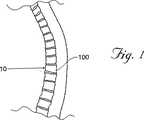
図1は、典型的なヒトの棘1を示し、ここで圧縮骨折10が腰椎100において生じている。図3に最もよく示されるように、椎骨100は骨折しており、上部板103および底部板104は、椎骨100の前壁10に向かって全体的に押し下げられ、そしてそれらの骨折前の通常の平行な配向(平行線90として概して示されている)から離れる。
【0023】
図4は、図3の椎骨の冠状(頂面)図を示す。椎骨100は、椎体105を含み、これは椎骨100の前(すなわち、前面(front)または胸部(chest))側上に延びる。椎体105は、ほぼ楕円板の形状であり、前壁10および後壁261を含む。椎体105のジオメトリーは、一般的に対称的である。椎体105は、緻密皮質骨110から形成される外部を含む。皮質骨110は、網状海綿質(cancellous or spongy)の骨115(髄様骨または海綿質(trabecular)ともいう)の内部容積を囲う。
【0024】
脊柱管150は、各椎骨100の後(すなわち、背部)側に位置する。脊髄151は、脊柱管150を通る。椎弓135は、脊柱管150を取り囲む。椎弓135の左右の茎120は、椎体105に隣接する。棘突起130は、椎弓135の後部から延びており、左右の横突起125および乳頭突起126も同様に延びる。
【0025】
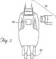
図2は、本発明の開示される方法のために準備された患者50を示す。これらの手順は、開示される手順を行うように適切に訓練されそして資格を与えられた医療専門家により外来患者または入院患者(inpatient)ベースで行われ得る。望ましくは、患者は、外科的手順の間、全身麻酔または局所麻酔下におかれる。
【0026】
本発明の1つの実施形態において、外科的方法は、挿入デバイス350(図5Aを参照のこと)を、好ましくは図2に60として示されるような背部の標的領域を通して、骨(例えば、骨折した椎体105)に経皮的に挿入する工程を包含する。挿入デバイス350は、好ましくは鋭利な末端を有する、任意の型および大きさの中空の装置であり得る。1つの好ましい実施形態において、挿入デバイス350は、直径約11ゲージの中空針を備える。11ゲージ針は、この手順に好ましい。なぜならば、この針は、種々の器具および材料の通過を可能にするのに十分な大きさの中空チューブキャビティを組み込むが、この針の全体の大きさは、患者における骨および組織の損傷を最小にするのに十分な程小さいからである。しかし、種々のその他の大きさの針アセンブリ(6〜14ゲージの針を含む)が、本発明のデバイスおよび方法と共に使用され得、種々の結果を与えることが理解されるべきである。さらに、種々の他のアクセス器具(例えば、米国特許第4,969,888号、同第5,108,404号、同第5,827,289号、同第5,972,015号、同第6,048,346号、および同第6,066,154号(これらの各々が本明細書中で参考として援用される)に記載されるような器具)は、種々の結果を伴い、本発明の技術により使用され得る。
【0027】
挿入デバイス350は、好ましくは、強固な非反応性の医療等級の材料(例えば、外科用スチール)から構成される。所望される場合、挿入デバイス350は、操作アセンブリに装着される。この操作アセンブリは、非反応性で医療等級の材料から構成され、この材料としては、プラスチック、セラミック、金属、複合材、アクリロニトリル−ブタジエン−スチレン(ABS),ポリエチレン、ポリプロピレン、ポリウレタン、テフロン(登録商標)、または外科用スチールが挙げられるがこれらに限定されない。図5Aは、本発明の種々の実施形態と共に典型的に使用される市販の針アセンブリを示し、これらは、さらに以下に記載される。
【0028】
図5Aに示されるように、11ゲージ生検針(Franklin Lakes,NJのBecton Dickinson & Coから市販される)のような挿入デバイス350は、背部の軟質組織を通って椎体105に挿入され得る。一般的に、このような手順のためのアプローチは、経茎的(transpedicular)であるが、当業者に周知の処置レベルおよび/または邪魔になる解剖学的特徴に依存して、種々のその他のアプローチ(側方アプローチ、茎外(extrapedicular)アプローチおよび/または前方アプローチを含む)が使用され得る。1つの実施形態において、デバイス350は、当該分野で周知のように、針本体348およびスタイレット349を備える。デバイス350の挿入の間、デバイス350の位置は、望ましくは可視化装置(例えば、リアルタイムX線、CTスキャン装置70(図2を参照のこと)、MRI、または当業者に一般的に使用される任意の他のモニタリング装置)を使用してモニタリングされる。これらの装置としては、BrainLab CorporationまたはGeneral Electric Corporationから市販されるシステムのようなコンピュータ補助誘導装置およびマッピング装置を含む。
【0029】
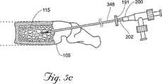
1つの好ましい実施形態において、挿入デバイス350の遠位端351は、椎体105において、好ましくは椎体105の後側に向いた位置に位置付けられる。所望ならば、遠位端351は、前側向きを含めて、椎体105全体の種々の場所に位置付けられ得る。一旦位置決めされると、挿入デバイス350のスタイレット349は取外され(図5Bを参照のこと)、そしてキャビティ形成デバイス200が、シャフト348を通って椎体105に挿入され得る。図5Cを参照のこと。キャビティ形成デバイス200(これは、望ましくは生物学的に適合性でかつ医療用に許容可能な材料で構成される)は、小さな機械的タンプ(tamp)、リーマー、穿孔機、バルーンカテーテル(以下に記載される)または海綿質を移動させ得る任意の適切なデバイスであり得る。一旦キャビティ形成デバイスが椎体105内に位置付けられると、このデバイスを使用して、海綿質115を移動して、それによりキャビティ170を生成する。図5Fを参照のこと。
【0030】
図9および10に示される1つの実施形態において、キャビティ形成デバイスは、バルーンカテーテル200を備える。バルーンカテーテル200は、望ましくは椎体の少なくとも20%を横切って延びるが、生成されるキャビティの所望の大きさに依存して、これよりも多いかまたは少ない量を延び得る。この実施形態において、バルーンカテーテル201が膨張するにつれて、海綿質は、制御された様式でキャビティ170から全体的に外へと除去され、望ましくはキャビティ170の外周辺のかなりの部分の周りに、圧縮された骨の領域172を形成する。
【0031】
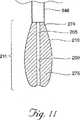
バルーンカテーテル200(これは以下により詳細に記載される)は、シャフト348の中空内部を通って椎体105へと適合するような大きさにされるかまたは折り畳まれる。一旦、椎体105内の所望の位置に位置すると、バルーンカテーテル190は、医療適用における使用に適切な加圧充填媒体275(空気、窒素、生理食塩水または水を含むがこれらに限定されない)で満たされる。図5Dおよび11を参照のこと。好ましい実施形態において、充填媒体275は、放射線不透性流体(例えば、St.Louis,MOのMallinkrodt,Inc.から市販されるConray(登録商標)液)であり、この流体により、医師は、膨張の間、カテーテル190を可視化し得る。所望の場合、カテーテルを膨張させる代替方法(機械的エキスパンダー、ジャッキ、拡張スプリングおよび/または膨張/発泡剤を含む)が種々の結果を伴って使用され得る。
【0032】
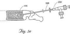
1つの実施形態において、カテーテル201は、任意の適切な容積まで膨張されて、椎体105内にキャビティ170を生成する。好ましい実施形態において、カテーテル201は、少なくとも容量が0.20ccまで膨張されるが、骨質および骨密度に依存して、1、2、4、6、または8ccのような有意に大きなサイズまで膨張され得る。キャビティを生成した後、カテーテル201は、収縮され(図5Eを参照のこと)、そして椎体105およびシャフト348から除去される。(図5Fを参照のこと)。骨充填剤180を、針本体348に適合性の任意の型のプランジャー、押出し機および/またはフィードラインアセンブリ349を使用して、シャフト348を通して椎体105に導入する。一旦骨充填剤の注入が完了すると、シャフト348が引き抜かれ得る。
【0033】
所望の場合、バルーンカテーテル201の一部は、一時的または永久に椎体105内に残され得る。例えば、キャビティ形成および膨張媒体の除去の後、バルーンカテーテル201の収縮膨張部分は、骨充填剤180で再充填されて、椎体105内に残され得る。あるいは、膨張媒体275は、骨充填剤180を含み得る。バルーンカテーテル201がこのような膨張媒体で充填された後、カテーテル201の少なくとも一部は、永久にキャビティ170内に残され得る。代替の実施形態において、カテーテル201(キャビティ170内に残ることを意図される)は、生体吸収性材料および/または拡張可能な構造体として布帛/メッシュ材料を備え得る。
【0034】
キャビティ170の生成の際に、カテーテル201の膨張は、拡張可能な材料210を海綿質115に対して押し出させ、これがキャビティ170の周辺部の大部分に沿って圧縮骨領域または「シェル」172を形成し得る。このシェル172は、望ましくは骨充填剤180がキャビティ170から出るのを阻止するかまたは防止し、それにより骨充填剤の溢出を阻止し、かつ/または所望の場合、キャビティ内での骨充填剤180の加圧を容易にする。キャビティ170内の圧力が増加するにつれて、キャビティ170の壁は、骨充填剤180によって、望ましくはさらに外側に押しやられ、椎体105内のさらなる海綿質を圧縮し、かつ/またはキャビティ170のサイズを増大させる。十分な圧力が利用可能であり、そしてシェル172の完全性が、骨充填剤180が有意に漏れることなしに維持され得る場合、骨折した皮質骨を動かし得る圧力が発生され得る。
【0035】
本発明の1つの実施形態において、キャビティ形成の後、一定量の材料(例えば、骨充填剤180)は、低圧下でシャフト348を通って椎体105に導入される。骨充填剤の量は、望ましくはキャビティ170の容積より大きいが、より少ない骨充填剤が種々の結果を伴って導入され得る。一旦キャビティ170が実質的に充填されると、骨充填剤180の続きの導入は、望ましくはキャビティ170内の骨充填剤180を加圧し、その結果、増加した圧力が、キャビティ壁の少なくとも一部を外側に移動させ、それによりキャビティ170を拡大し、そしてさらに海綿質を圧縮し、かつ/または皮質骨を移動させる。望ましくは、骨充填剤180の導入は、骨充填剤の椎体からの漏出が切迫しているように見えるか、皮質骨が骨折前の位置を回復したか、かつ/または医師が、十分な骨充填剤180が骨内に注入されたと決定するまで続けられる。所望の場合、医師は、キャビティ形成デバイスを利用して、骨充填剤のためのさらなるキャビティを生成し得るか、またはシャフト348が椎体から除去されてこの手順を完了し得る。
【0036】
骨充填剤180は、整形外科手術で使用される任意の適切な充填剤料であり得、これらの材料としては、同種移植片組織もしくは自家移植片組織、ハイドロキシアパタイト、エポキシ、PMMA骨セメント、または合成代用骨(Wright Medical Technology, medical grade plaster of parisからのOsteoset(登録商標)、Norian CorporationからのSkeletal Repair System(SRS(登録商標))セメント、またはZimmerからのCollagraft等)が挙げられるが、これらに限定されない。骨充填剤180が椎体105に導入されるにつれて、この導入は、骨充填剤180が椎体105の外側に流出しないことを確実にするために、望ましくはX線透視検査または任意の他の適切なモニタリングデバイスもしくは方法によりモニタリングされる。可視化を容易にするために、骨充填剤180は、透視検査剤(例えば、放射線不透性の硫酸バリウム)と混合され得る。別の実施形態において、骨充填剤180は、骨セメントの混合物およびチキソトロピー材料(これは、望ましくは骨セメントの溢出を制限および/または防止する)を含み得る。
【0037】
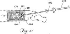
図5G〜5Lに示される、開示される方法の代替の実施形態において、第1の骨充填剤180は、キャビティ170内に導入され、第1の骨充填剤180の量は、望ましくはキャビティ170の容積より少ないか、またはキャビティ170の容積にほぼ等しい。例えば、キャビティ170を生成するために利用されたバルーンカテーテル200が1.0ccの膨張流体で膨張される場合、約1.0cc以下の骨充填剤180は、最初にキャビティ170内に注入される。当然のことながら、所望の場合、キャビティの容積より多い量の第1の骨充填剤180は、キャビティ内に注入され得る。次いで、シャフト348は、椎体105内に再び位置付けられ、(図5Hを参照のこと)デバイス350の遠位端351は、望ましくはキャビティ170に含まれる第1の骨充填剤180のボーラス400内に位置する。図5Iに最もよく示されるように、次いで第2の量の骨充填剤182は、椎体105中に注入され、この充填剤は、望ましくは第1の量の骨充填剤180を、キャビティ170の壁に対して外側に追いやる。望ましくは、第1の量の骨充填剤180は、キャビティ170からの溢出に耐え、キャビティ170の壁に対して外側に押し、さらに海綿質115を圧縮しかつ/またはキャビティ170のサイズを増大させる。第2の量の骨充填剤182の導入は、望ましくは椎体からの骨充填剤の漏出が切迫しているように見えるか、皮質骨がその骨折前の位置を回復したか、かつ/または医師が、十分な骨充填剤180が骨に注入されたと決定するまで、続けられる。所望の場合、医師は、カテーテル200を再挿入して、さらなるキャビティを生成し得るか、またはシャフト348が除去されてこの手順を完了し得る。
【0038】
図8A〜8Cは、開示される方法の代替の実施形態を示し、ここで、医師は、第1の材料(例えば、骨充填剤180)をキャビティ170に導入し、続いてキャビティ形成デバイス200を骨に挿入する。次いで、このキャビティ形成デバイス200は、拡張され、そして望ましくは、この骨充填剤180をこのキャビティの壁に対して圧縮し、任意の有意な亀裂および/またはセメントが流れる静脈通路を密封する。1つのさらなる実施形態において、医師は、このキャビティ形成デバイスを取り出す前および/または第2の材料(例えば、骨充填剤)を導入する前に、第1の骨充填剤を部分的または完全に硬化させるために、待ち得る。続いて、この第2の材料(示されず)は、ほとんど漏出の心配なく、椎体に注入され得る。所望ならば、この方法は、セメント漏出が差し迫っているようである場合はいつも使用され得、そして医師が十分な骨充填剤180が骨に注入されたことを決定するまで、複数回繰り返される。さらに、医師は、皮質骨がその以前に骨折した位置を快復するまで、この手順を繰返し得る。代替の実施形態において、医師は、第1の骨充填剤の導入の前にキャビティ形成デバイスを使用し、次いでこの第1の骨充填剤をキャビティに導入し、続いて記載される方法の1つ以上に従う。
【0039】
第1の骨充填剤は、望ましくは、キャビティに導入され得るが、第2の骨充填剤がこのキャビティに注入される場合に、このキャビティおよび/または椎体からの溢出に耐える材料を含む。本発明の一実施形態において、この第1および第2の骨充填剤は、骨セメントを含み、第1の骨セメントは、第2の骨セメントより溢出に対して抵抗性である。例えば、第1の骨セメントの成分は、第1の骨セメントが第2の骨セメントより速く硬化するように、特別に適応され得る。あるいは、この第1の骨セメントは、第2の骨セメントの前に調製され、そして/または椎体に導入され、第2の骨セメントの前に第1の骨セメントが部分的にかまたは完全に硬化され得る。あるいは、第1の骨セメントの硬化(curing)および/または固化(hardening)は、(例えば、熱を適用することによって)促進されるか、または第2の骨セメントの硬化および/または固化は、(例えば、冷却によって)遅延され得る。別の実施形態において、この第1および第2の骨充填剤は、骨セメントを含み、第1の骨セメントは、望ましくは、第2の骨セメントより粘性である。別の代替の実施形態において、この第1の骨充填剤は、拡張可能構造体(例えば、ステント)を含む。
【0040】
別の実施形態において、第1の骨充填剤は、第2の骨充填剤より粘性の材料を含み、この第1および第2の骨充填剤は、異なる材料を含む。別の実施形態において、この第1の骨充填剤は、第2の骨充填剤よりも海綿質への溢出に対してより抵抗性である材料を含む。別の実施形態において、第1の骨充填剤は、第2の骨充填剤中の粒子よりも一般的に大きな粒子を有する材料を含む。さらなる実施形態において、第1の骨充填剤の粒子は、一般的に、海綿質内の平均細孔サイズよりも大きい。別の実施形態において、第1の骨充填剤は、硬化可能(settable)材料(例えば、ツーパートプラスチック材料または他の硬化可能(curable)生体材料)を含む。
【0041】
図16A〜16Dは、開示される方法の代替の実施形態を示し、ここで、第1の材料(例えば、骨充填剤180)は、最初に、ヒト骨の海綿質115(例えば、椎体105)に導入される。続いて、拡張可能構造体210(例えば、バルーンカテーテル200の遠位端において見られるような構造体)が、椎体105に挿入される。次いで、拡張可能構造体210は、拡張され、これは骨充填剤180および/または海綿質115をずらし、椎体105内にキャビティ170を作製する。一実施形態において、拡張可能構造体210の拡張は、骨充填剤180を海綿質115の方にさらに押しつけ、そして/または海綿質をさらに圧迫する。骨充填剤180の漏出を最小化するために、この骨充填剤は、拡張可能構造体210の拡張の前に、部分的にかまたは完全に固化され得る。あるいは、この拡張可能構造体210が拡張され得、そして骨充填剤180は、この拡張可能構造体210の周りで部分的または完全に同化され得る。いずれの場合においても、第2の材料(任意のさらなる骨充填剤)は、キャビティ170に導入され得る。一実施形態において、この第2の材料は、静止位置において骨を支持する材料である。この方法は、セメント漏出が差し迫っているようである場合はいつも使用され得、そして医師が、十分な量の様々な材料が骨に導入されたことを決定するまで、複数回繰り返され得る。あるいは、この医師は、皮質骨領域または以前骨折した位置付近の場合には、充填材料の導入を停止し得る。
【0042】
海綿質内にキャビティおよび/または好ましい流路を作製することによって、本発明は、海綿質への骨充填剤の非常に高圧の注入の必要性を排除する。所望ならば、骨充填剤は、大気圧および/または周囲圧においてかまたはその付近で、あるいは、約400ポンド/平方インチ未満の圧力で、骨充填剤送達システム(例えば、PCT公開番号WO00/09024(これは本明細書中で参考として援用される)に記載されるシステム)を使用して、骨に注入され得る。従って、より粘性の骨充填剤(例えば、濃化骨セメント)が、低圧下で骨に注入され得(例えば、周囲圧または大気圧におけるかまたはその付近の送達圧で、送達デバイスを出る)、骨の外側のセメント漏出および/または溢出の機会を減少する。
【0043】
(キャビティ形成デバイス)
本発明はまた、開示される本発明の技術に従って構築されるキャビティ形成デバイスを含む。一実施形態において、このキャビティ形成デバイスは、図9、10および11に示されるように、バルーンカテーテル201を備える。このカテーテルは、中空チューブ205を備え、この中空チューブ205は、望ましくは、医療グレードの材料(例えば、プラスチックまたはステンレス鋼)から構成される。この中空チューブ205の遠位端206は、一般的にバルーンカテーテルに使用されるような可撓性材料(金属、プラスチック、複合材料、ポリエチレン、マイラー、ゴムまたはポリウレタンを含むが、これらに限定されない)から構成される拡張可能材料210により囲まれる。1つ以上の開口部250は、遠位端206付近のチューブ205に配置され、望ましくは、このチューブ205の中空内部と、このチューブ205とこの拡張可能構造体210との間に形成される管腔との間の流体連絡を可能にする。1つ以上の膨張ポート222、224を有する継手220は、このチューブ205の近位端207に固定される。この実施形態において、一旦、カテーテル201が、椎体105内の所望の位置に存在すると、膨張媒体275は、この膨張ポート222を通してこの継手220に導入され、ここで、この媒体は、継手220を通り、中空チューブ205を通り、開口部(単数または複数)250を通って、拡張可能構造体210と中空チューブ205との間の管腔274に移動する。この膨張媒体275が注入される場合、この膨張媒体275の圧力は、この拡張可能構造体210を中空チューブ205から離され、この拡張可能構造体210を外向きに膨張させ、それにより海綿質115を圧縮し、そしてキャビティ170を形成する。一旦、所望のキャビティサイズが達成されると、この膨張媒体275は、カテーテル200から引き出され、この拡張可能構造体は、キャビティ170内で圧潰し、そしてカテーテル200が引き出され得る。
【0044】
例えば、本発明の1つの好ましい実施形態に従って構築されるバルーンカテーテル201は、11ゲージの針と共に使用するために適切であり、このカテーテル201は、0.035インチの外径および10.75インチの長さを有する中空ステンレス鋼皮下チューブ205を備える。1つ以上の開口部250が、このチューブ205の遠位端から約0.25インチの所に形成される。好ましい実施形態において、中空チューブ205の遠位端206は、当該分野で周知の任意の手段(接着剤を含む)を使用して密閉して閉じられる。
【0045】
一実施形態において、中空チューブ205は、プラスチックの押出し成形したチューブを備える拡張可能構造体210により実質的に取り囲まれる。一実施形態において、このプラスチックチューブは、0.046インチの内径、0.082インチの外径、および91/2インチの長さを有する。このプラスチックチューブの遠位端206は、当該分野で公知の手段(例えば、適切な接着剤)によって、中空チューブ205の遠位端に結合される。あるいは、このプラスチックチューブは、当該分野で周知の手段によって、中空チューブ205の遠位端206の周りで熱密閉され得る。3/16インチの外径を有する熱収縮チューブ215の3/4インチ長の部品は、プラスチックチューブの近位端の周りに固定され得る。一実施形態において、中空チューブ205の近位端は、継手220に挿入され、そして熱収縮チューブ215は、望ましくは、当該分野で公知の適切な接着剤を使用して、継手220に結合される。この継手220は、多数の部品メーカーから市販されるルアーT型継手であり得、当業者に公知の任意の適切な材料から作製され得る。この継手220は、さらなる機器(例えば、ポンプおよびシリンジ(示されず))への取付けのために、1つ以上のポート222、224を備える。所望ならば、この中空チューブ205は同様に、適切な接着剤を使用して、この継手220に結合され得る。あるいは、図12に示されるように、拡張可能構造体210は、この中空チューブ205より有意に短くあり得、そしてその遠位端206およびその近位端209において、中空チューブ205に結合される。
【0046】
この中空チューブ205および1つ以上の開口部250は、開示される手順の間、カテーテルからの膨張媒体の引き出しを容易にする。カテーテルが収縮している場合、この拡張可能構造体210は、通常、チューブ205に対して圧潰し、このチューブ205は、しばしば管腔を密閉して閉じ(少なくとも1つの第2の引き出し経路の非存在下で)、そしてカテーテルの拡張可能構造体210からの膨張媒体のさらなる引き出しを阻止する。しかし、開示される本発明の実施形態において、チューブ205の遠位端付近の1つ以上の開口部250により、膨張媒体275は中空皮下チューブ205を通して引き出され、拡張可能構造体210をさらに収縮し得る。この中空皮下チューブ205の強固な壁は、膨張媒体を排除する真空下における圧潰に抵抗し、膨張媒体のための流路を維持し、そしてカテーテルから膨張媒体を迅速に引き出し、このことは、望ましくは、たった数秒のカテーテルの収縮を可能にする。
【0047】
開示される実施形態において、カテーテル201が膨張される場合、膨張媒体275は、代表的には、拡張可能構造体210と中空チューブ205との間の管腔全体を満たし、カテーテル201をこの拡張可能構造体210の長さ全体に沿って拡張しようとする。しかし、カテーテル201の大部分が、シャフト348の管腔内に位置され、カテーテル201の遠位端206は、椎体105内に伸張するため、シャフト348は、望ましくは、拡張可能構造体210の拡張を制限し、主にカテーテル200の遠位端206において、拡張可能構造体210を拡張させる。望ましくは、カテーテル201のさらなる挿入または引き出しは、シャフト348の遠位端から伸張する拡張可能構造体210の量を変え、これにより椎体105内を自由に拡張する拡張可能構造体210の長さを増加または減少する。椎体105へ挿入するカテーテル201の量を選択することによって、医師は、外科的手順の間、拡張可能構造の長さを変え、最終的にカテーテル201により生成されるキャビティ170のサイズを変え得る。従って、開示される実施形態は、様々な長さの複数のカテーテルの必要性を排除および/または軽減し得る。所望ならば、マーク269(図9を参照のこと)が、シャフト348から伸張するカテーテル201の長さに対応するカテーテルの近位端に沿って配置され得、これにより医師は、椎体105内のカテーテル200の拡張可能構造体210のサイズを判断し得る。同様に、以下に開示される代替の実施形態において、キャビティ形成デバイス201は、シャフト348の先端部を越えて伸張する剛毛425の長さに対応するマークを取込み得る。
【0048】
図13に示される代替の実施形態において、カテーテルの拡張可能部分211の長さは、第2の位置214に中空チューブ205に沿って拡張可能構造体210を固定および/または接着し、それにより第2の位置214を越える拡張を制限することによって、さらに制限され得る。例えば、拡張可能部分211の所望の最大長さが3インチである場合、この拡張可能構造体210は、中空チューブ205の遠位端206から約3インチ離れた第2の位置214で、中空チューブ205に固定され得る。望ましくは、この配置により、医師は、カテーテル201の残りの部分203の拡張を制限および/または防止しつつ、3インチまでの拡張可能部分211の拡張長さを選択し得る。この配置はまた、シャフト本体348の近位端191から伸張するカテーテルの部分202の望まない拡張を防止し得る(図5Cを参照のこと)。
【0049】
上記のように、開示される実施形態において、拡張可能構造体は、望ましくは、中空チューブの遠位端に固定され、このことは、この拡張可能構造体210が、例えば完全な放射状の引き裂きにより引き裂かれたかまたは傷付けられた場合、拡張可能構造体210の断片の回収を容易にする。中空チューブ205は望ましくは、拡張可能構造体210の断片(示されず)に取り付けられたままであるため、これらの断片は、中空チューブ205と共に椎体105から引き出され得る。さらに、遠位取り付けは、望ましくは、中空チューブ205の長手軸に沿った拡張可能構造体210の有意な拡張を防止および/または軽減する。
【0050】
図17は、本発明の代替の実施形態に従って構成された、キャビティ形成デバイス300を示す。この実施形態の多くの特徴は、先に記載した実施形態と類似であるので、同様の参照番号が、同様の構成要素を示すために使用される。この実施形態において、中空チューブ205は、フィッティング220(例えば、T型フィッティング)を通って延び、そしてキャップ310に固定される。好ましい実施形態において、中空チューブ205は、フィッティング220に対して回転し得る。所望であれば、シール(図示せず)(例えば、シリコーンまたはTeflon(登録商標)のOリング)が、近位フィッティング222に組み込まれて、中空チューブ205を通る膨張媒体の漏出を制限および/または防止し得る。
【0051】
使用中に、キャビティ形成デバイス300は、先に記載した実施形態と類似の様式で、海綿質を圧縮し、そして/またはキャビティを形成する。しかし、一旦、キャビティが形成され、そしてデバイス300の引き抜きが所望されると、キャップ310が回転され得、拡張可能材料210をフィッティング220に対してねじり、そして拡張可能構造体210を中空チューブ205に対して引く(望ましくは、デバイス300の拡張可能な部分の外径全体を最小にする)。次いで、デバイス300は、シャフト348を通して容易に引き抜かれ得る。拡張可能な構造体210が可塑的に変形したか、または何らかの様式で故障した場合でさえも、この実施形態は、容易な引き抜きおよび/または挿入のために、拡張可能な構造体210が中空チューブ205の周囲に巻かれることを可能にする。あるいは、中空チューブ205は、フィッティング220の長手方向軸に対して移動可能であり得、このことは、拡張可能な構造体210を、中空チューブ205に対してさらに伸縮させる。
【0052】
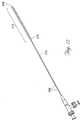
図6Aおよび6Bは、本発明の代替の実施形態に従って構成された、キャビティ形成デバイス410を示す。キャビティ形成デバイス410は、挿入デバイス350のシャフト348を通るように所望の大きさにされる、シャフト420を備える。ハンドルアセンブリ415(これは、キャビティ形成デバイス410の操作を容易にする)が、シャフト420の近位端412に固定されている。1つ以上のワイヤまたは「剛毛」425が、シャフト420の遠位端423に固定されている。剛毛425は、溶接、ハンダ付け、接着または当該分野において周知の他の固定手段によって、シャフト420に固定され得る。あるいは、剛毛425は、シャフト420と一体的に形成され得るか、またはレーザーもしくは当該分野において周知の他の手段を使用して、シャフトからエッチングされ得る。剛毛およびシャフトは、強靭な非反応性の医療等級の材料(例えば、外科用鋼鉄)で形成され得る。1つの実施形態において、剛毛425は、シャフト425の長手方向に沿って延びるが、シャフトの軸からわずかに外向きに放射する。この様式で、剛毛425は、シャフト348を通過するために収集または「収束」され得るが、シャフト348から出る際には拡張または「扇状に広がり」得る。所望であれば、これらの剛毛は、海綿質115への通過を容易にするために、直状または湾曲状であり得る。さらに、所望であれば、1つ以上の剛毛425は中空であり得、デバイス410の挿入の間に、開業医が海綿質の生検サンプルを採取することを可能にする。
【0053】
図7に示すように、キャビティ形成デバイス410は、望ましくは、標的の骨(例えば、椎体105)に位置するシャフト348を通して挿入され得る。剛毛425が海綿質115に入るにつれて、剛毛425は、望ましくは、骨115を移動させ、そして1つ以上のキャビティ426または好ましい流路を、椎体に作製する。所望であれば、開業医は、剛毛425をシャフト348内に引き戻し、キャビティ形成デバイス410を再配置し(例えば、デバイス410を回転させることによって)、そして剛毛425を再挿入し、これによって、海綿質115においてさらなるキャビティを作製し得る。
【0054】
キャビティ形成デバイス410の除去の後に、骨充填剤のような材料(図示せず)が、シャフト348を通して導入され得る。骨充填剤は、望ましくは、剛毛425によって作製されたキャビティ426を通って初めに移動する。所望であれば、開業医は、骨充填剤の導入を中断し得、そしてキャビティ形成デバイス410を再挿入することによって、さらなるキャビティを作製し得る。さらに、骨充填剤の漏出が起こるかまたは起こりそうである場合には、開業医は、骨充填剤の注入を中断し、上記のようにさらなるキャビティを作製し、導入された/漏出した骨充填剤が十分に固化してさらなる管外遊出に抵抗性となるまで待ち、その後、骨充填剤の導入を続け得る。先に記載したように、骨充填剤は、結果が変化する多くの異なる材料または材料の組合せを含み得る。
【0055】
図14は、本発明の代替の実施形態に従って構成された、キャビティ形成デバイス500を示す。キャビティ形成デバイス500は、挿入デバイス350のシャフト348を通過する大きさにされた、シャフト520を備える。ハンドルアセンブリ515(これは、キャビティ形成デバイス500の操作を容易にする)が、シャフト520の近位端512に固定されている。望ましくは、キャビティ形成デバイス500のシャフト520は、挿入デバイス350のシャフト348より長い。シャフト520の遠位端525は、海綿質115への通過を容易にすると考えられ得(図示せず)、または椎体105の前壁10を貫通する機会を最小にするように、丸められるかもしくは平坦にされ得る。さらに、所望であれば、シャフト520の遠位端525は、中空であり得(図示せず)、開業医がデバイス500の挿入の間に海綿質115の生検サンプルを採取することを可能にする。
【0056】
図15は、本発明の代替の実施形態に従って構成された、キャビティ形成デバイス600を示す。キャビティ形成デバイス600は、挿入デバイス350のシャフト348を通過するような大きさにされた、シャフト620を備える。ハンドルアセンブリ615(これは、キャビティ形成デバイス600の操作を容易にする)が、シャフト620の近位端612に固定されている。シャフト620は、望ましくは、挿入デバイス350のシャフト348より長い。シャフト620の遠位端625は、海綿質115を通る通過を容易にすると考えられ(図示せず)、または椎体105の前壁10の貫通の機会を最小にするために、丸められるかもしくは平坦にされ得る。この実施形態において、デバイス600の遠位端625は、ドリルねじ627を組み込み、これは、海綿質115を通してのデバイス600の前進を容易にし得る。さらに、所望であれば、シャフト620の遠位端625は、中空であり得、開業医がデバイス600の挿入の間に海綿質115の生検サンプルを採取することを可能にする。
【0057】
デバイスの除去の後に、骨充填剤(図示せず)が、シャフト348を通して導入され得る。望ましくは、この骨充填剤は、このデバイスによって作製されたキャビティを通って初めに移動する。所望であれば、開業医は、骨充填剤の導入を中断し得、そしてこのデバイスを再挿入することによって、さらなるキャビティを作製し得る。さらに、骨充填剤の漏出が起こるかまたは起こりそうな場合には、開業医は、骨充填剤の導入を中断し、上記のようにさらなるキャビティを形成し、導入された/漏出した骨充填剤が十分に固化するのを待ち、その後、骨充填剤の導入を続け得る。先に記載したように、骨充填剤は、結果が変化する多くの異なる材料または材料の組み合わせを含み得る。
【0058】
図18〜20は、本発明の別の代替の実施形態に従って構成された、キャビティ形成デバイス600aを示す。このデバイスの構成要素の多くは先に記載したものと類似であるので、類似の参照番号が、類似の構成要素を示すために使用される。キャビティ形成デバイス600aは、シャフト620aを備え、このシャフトは、挿入デバイス350のシャフト348を通過するための大きさにされる。ハンドルアセンブリ615a(これは、キャビティ形成デバイス600aの操作を容易にする)が、シャフト620aの近位端612aに固定される。シャフト620aは、望ましくは、挿入デバイス350のシャフト348より長い。シャフト620aの遠位端625aは、海綿質115への通過を容易にするために、丸められるかまたは面取りされ得、あるいは椎体105の前壁10を貫通する可能性を最小にするために、平坦にされ得る。
【0059】
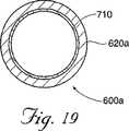
開口部またはウィンドウ700が、望ましくは、シャフト620aに形成される。図19および20に示すように、拡張可能な構造体710が、シャフト620aの少なくとも部分的に内部に、望ましくはウィンドウ700に隣接した位置に、配置される。シャフト620aを通って延びる管腔を通しての膨張流体の導入の際に、拡張可能な構造体710が拡張し、そして拡張可能な構造体710の少なくとも一部が、ウィンドウ700を通ってシャフト620aの外側に延びる。望ましくは、この構造体が拡張し続ける場合に、拡張可能な構造体710は、ウィンドウ700を通って「成長」し(図20のP1→P2→P3へと)、これによって、海綿質を圧縮し、キャビティを作成し、そして/または海綿質を移動させる。拡張可能な構造体710の収縮の際に、拡張可能な構造体710の大部分は、望ましくは、このツールを椎体から除去するために、シャフト620a内に引き戻される。1つの実施形態において、拡張可能な構造体710を構成する材料の少なくとも一部は、この構造体が拡張するにつれて可塑的に変形する。
【0060】
拡張可能な構造体710は、医療デバイスの適用において一般的な、可撓性の材料(プラスチック、ポリエチレン、マイラー、ゴム、ナイロン、ポリウレタン、金属、セラミックまたは複合材料が挙げられるが、これらに限定されない)から構成され得る。望ましくは、シャフト620aは、拡張可能な構造体710の材料より拡張に対して抵抗性の材料(ステンレス鋼、セラミック、複合材料および/または硬質プラスチックが挙げられるが、これらに限定されない)を含む。代替の実施形態において、拡張可能な構造体710およびシャフト620aに対して、類似の材料であるが、異なる厚みおよび/または量で使用され得、これによって、拡張可能な構造体がシャフト620aの材料より拡張しやすくされる。拡張可能な構造体710は、当該分野において周知の種々の手段(溶接、融解、接着などのような手段が挙げられるが、これらに限定されない)によって、シャフト620aに直接結合され得る。代替の実施形態において、拡張可能な構造体は、シャフト620aの内側または外側に、あるいはその組合せで、固定され得る。
【0061】
先に記載したように、キャビティ形成デバイス500、600および600aのいずれかが、標的の骨(例えば、椎体105)に位置するシャフト348を通して挿入され得る。このデバイスが海綿質115に入るにつれて、このデバイスは、望ましくは、骨115を移動させ、そして1つ以上のキャビティを、椎体に形成する。所望であれば、医師は、このデバイスをシャフト348内に引き戻し得、そして必要なように再挿入して、所望のキャビティを海綿質115に作製し得る。
【0062】
図18〜20のキャビティ形成デバイスの実施形態において、キャビティ形成デバイス600aは、付随する挿入デバイスなしで利用され得る。このような場合には、このキャビティ形成デバイスは、望ましくは、椎体の軟部組織および皮膚性骨/海綿質を貫通し得る、鋭利な遠位端を組み込む。所望であれば、この遠位端は、中空または中実の構成であり得る。同様に、拡張可能な構造体の大きさおよび構成、ならびにキャビティ形成デバイスの所望の強度に依存して、ウィンドウが、シャフト620aの周囲のいくらかの周囲に延び得る。
【0063】
1つ以上のキャビティを海綿質115内に作製することによって、本発明のキャビティ形成デバイスは、望ましくは、骨充填剤180のための好ましい流路を作製する。さらに、このキャビティ形成デバイスはまた、望ましくは、キャビティ外の他の天然の流路(例えば、海綿質の静脈および/または亀裂)を閉鎖および/またはブロックし得る。さらに、本明細書中に開示される方法およびデバイスを使用して、骨に既に導入された骨充填剤を操作し得る。従って、本発明は、椎体の外側へのセメントの漏出の可能性を低下させ、そして/または椎体の有意な部分にわたる骨充填剤の分布を改善する。さらに、本発明に記載される、キャビティおよび所望の流路の作製は、より大きな制御下で、そしてより低い圧力下で、より安全に生体材料を交換することを可能にする。
【0064】
上記特定の用途に加えて、本明細書中に開示されるキャビティ形成デバイスおよび方法は、弱化した、罹患した、そして/または破砕した骨、ならびに身体全体にわたる種々の位置にある他の器官の処置および/または補強における使用に、十分に適合される。例えば、開示されるデバイスおよび方法を使用して、補強材料および/または医薬(例えば、癌薬、置換骨細胞、コラーゲン、骨マトリックス、鉱物質除去したカルシウム、および他の材料/医薬)を、破砕し、弱化し、そして/または病変した骨に直接送達し得、これによって、これらの材料の効力を増加させ、弱化した骨を補強し、そして/または治癒を促進する。さらに、このような材料を身体内の1つの骨に注入することにより、医薬/材料が身体内の他の骨および/または器官に移動しそして/また配送されることが可能となり得、これによって、この材料および/または医薬が直接注入されない骨および/または他の器官の質を高める。
【0065】
本発明の他の実施形態および用途は、本明細書の考察および本明細書中に開示される本発明の実施から、当業者に明らかである。本明細書中で参照された全ての文献は、具体的かつ全体的に、本明細書中に参考として援用される。本明細書および実施例は、例示のみと考えられるべきであり、本発明の真の範囲および意図は、添付の特許請求の範囲によって示される。当業者によって容易に理解されるように、開示された実施形態の各々の変形および改変は、添付の特許請求の範囲によって規定される本発明の範囲内で、容易になされ得る。
【図面の簡単な説明】
【図1】 図1は、1つの椎骨における圧縮骨折をもつ脊柱の図である。
【図2】 図2は、手術を受けようとする患者の図である。
【図3】 図3は、圧縮骨折を示す腰椎の一部切り欠き側面図である。
【図4】 図4は、腰椎の頂頭図である。
【図5A】 図5Aは、椎体中に挿入された脊髄針を示す腰椎の側面図である。
【図5B】 図5Bは、脊髄針からスタイレットが取り除かれた、図5Aの腰椎の側面図である。
【図5C】 図5Cは、椎体中に挿入された本発明の1実施形態に従ってキャビティ形成デバイスが構成された、図5Bの腰椎の側面図である。
【図5D】 図5Dは、キャビティ形成デバイスが膨張した、図5Cの腰椎の側面図である。
【図5E】 図5Eは、キャビティ形成デバイスが収縮した、図5Dの腰椎の側面図である。
【図5F】 図5Fは、キャビティ形成デバイスが椎体から除去された、図5Eの腰椎の側面図である。
【図5G】 図5Gは、骨充填剤が椎体中に注入された、図5Fの腰椎の側面図である。
【図5H】 図5Hは、脊髄針がキャビティ中に進行した、図5Gの腰椎の側面図である。
【図5I】 図5Iは、第2の骨充填剤が椎体中に注入された、図5Hの腰椎の側面図である。
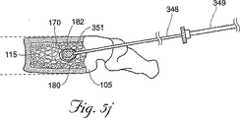
【図5J】 図5Jは、さらなる骨充填剤が椎体中に注入された、図5Iの腰椎の側面図である。
【図5K】 図5Kは、さらなる骨充填剤が椎体中に注入された、図5Jの腰椎の側面図である。
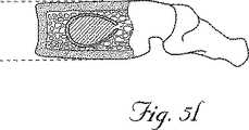
【図5L】 図5Lは、脊髄針が椎体から取り除かれた、図5Kの腰椎の側面図である。
【図6A】 図6Aは、本発明の代替の実施形態に従って構成されたキャビティ形成デバイスの側面図である。
【図6B】 図6Bは、図6Aのキャビティ形成デバイスの遠位端のクローズアップ図である。
【図7A】 椎骨中に挿入されている図6Aのキャビティ形成デバイスを示す腰椎の側面図である。
【図7B】 図7Bは、キャビティ形成デバイスが椎骨内に配置された図7Aの腰椎の側面図である。
【図7C】 図7Cは、キャビティ形成デバイスが椎骨から引き抜かれた図7Bの腰椎の側面図である。
【図8A】 図8Aは、本発明の教示に従う、椎体を処置する代替手順を示す、腰椎の側面図である。
【図8B】 図8Bは、キャビティ形成デバイスが骨充填剤中に挿入された、図8Aの腰椎の側面図である。
【図8C】 図8Cは、キャビティ形成デバイスがキャビティ中で拡張した、図8Bの腰椎の側面図である。
【図9】 図9は、本発明の1つの実施形態に従って構成されたキャビティ形成デバイスの側面図である。
【図10】 図10は、図9のキャビティ形成デバイスの遠位端のクローズアップ図である。
【図11】 図11は、膨張媒体によるバルーン材料の膨張を示す、針の遠位端から突出するバルーンカテーテルの遠位端のクローズアップ図である。
【図12】 図12は、本発明の代替の実施形態に従って構成されたキャビティ形成デバイスの側面図である。
【図13】 図13は、本発明の別の代替の実施形態に従って構成されたキャビティ形成デバイスの側面図である。
【図14】 図14は、本発明の別の代替の実施形態に従って構成されたキャビティ形成デバイスの側面図である。
【図15】 図15は、本発明の別の代替の実施形態に従って構成されたキャビティ形成デバイスの側面図である。
【図16A】 図16Aは、本発明の教示に従う椎体を処置するための代替手順を示す腰椎の側面図である。
【図16B】 図16Bは、骨充填剤が椎骨中に注入された図16Aの腰椎の側面図である。
【図16C】 図16Cは、キャビティ形成デバイスが椎骨中に挿入された図16Bの腰椎の側面図である。
【図16D】 図16Dは、キャビティ形成デバイスがキャビティ中で拡張した図16Cの腰椎の側面図である。
【図17】 図17は、本発明の別の代替の実施形態に従って構成されたキャビティ形成デバイスの側面図である。
【図18】 図18は、本発明の別の代替の実施形態に従って構成されたキャビティ形成デバイスの側面図である。
【図19】 図19は、図18のキャビティ形成デバイスの線19−19に沿った断面図である。
【図20】 図20は、図18のキャビティ形成デバイスの線20−20に沿った断面図である。[0001]
(Background of the Invention)
(Field of Invention)
The present invention relates to devices and methods for treating fractured bones and / or diseased bones. More particularly, the present invention relates to devices and methods for repairing, reinforcing and / or treating fractured bones and / or diseased bones using various devices (including cavity forming devices).
[0002]
(Background explanation)
Normal healthy bone is composed of a skeleton made from protein, collagen and calcium salts. Healthy bones are typically strong enough to resist the various stresses experienced by an individual during their normal daily activities, and normally vary in length of time to decline Can resist stronger stresses over time. However, osteoporosis or many other diseases (including diseases such as breast cancer, hemangiomas, osteolytic metastases or spinal myeloma injury), and long-term excesses of alcohol, tobacco and / or various drugs By use, healthy bones can be affected over time and significantly debilitated. If not examined, such factors can reduce bone strength, especially to the extent that bones are prone to fracture, collapse, and / or cannot resist even normal daily stress.
[0003]
Unfortunately, reduced bone strength is often difficult to detect until bone integrity has already been severely compromised. For example, the effects of osteoporosis are often not discovered until after a bone fracture has already occurred, at which point the overall bone strength of most patients is typically reduced to dangerous levels. Yes. Furthermore, long-term decline in bone strength is typically irreversible, mainly because most bone development occurs in children and early adulthood. Furthermore, many bone diseases (including osteoporosis, cancer and other bone-related disorders) cannot be cured routinely at the current stage of medical development.
[0004]
For a large number of individuals in an aging society group, the decline in undiagnosed bone strength and / or uncontrollable bone strength can cause these individuals' bones to such an extent that even routine activities pose a significant fracture threat. Already weakened. For example, if the spinal bone is significantly reduced, compressive forces in the spine can often cause vertebral body fractures and / or deformations. For sufficiently weakened bones, even normal daily activities, such as going down stairs or carrying grocery, cause the collapse of one or more spinal bones, just like chalk, under the compressed weight of a human foot. obtain. Vertebral fractures in this manner are typically referred to as vertebral compression fractures. Researchers estimate that at least 25% of all women over the age of 50, and some less, men suffer from one or more vertebral compression fractures due to osteoporosis alone. In the United States, it is estimated that more than 700,000 vertebral compression fractures occur each year, of which more than 200,000 people are required some form of hospitalization. Other commonly occurring fractures that result from weakened bones can include hip, wrist, knee, and tarsal joint fractures, to name a few.
[0005]
Fractures such as vertebral compression fractures often cause the onset of pain, which is chronic and severe. Apart from the pain caused by the fracture itself, spinal column involvement can cause nerve contraction and / or damage, causing complete paralysis, loss of function and severe pain that dissipates across the patient's body. However, even if it does not affect the nerves, this severe pain associated with all types of fractures is debilitating, causing numerous stresses, disability mobility and other long-term consequences. For example, progressive vertebral fractures can cause severe deformities of the spine ("dorsal dorsum") over time, cause individuals to fall back, and can also cause significant pulmonary decline and increased mortality.
[0006]
Until recently, treatment choices for vertebral compression fractures, and other severe fractures and / or losses in bone strength, have mainly been strong oral or intravenous dosing with reduced results, reduced activity, brace of Extremely limited to handling pain with bracing and / or radiation therapy. Because patients with these problems are typically older and often suffer from various other important health complications, many of these individuals cannot tolerate invasive surgery. Furthermore, to prevent further loss of bone strength, many patients receive hormonal and / or vitamin / mineral supplements, again with comparable results and often significant side effects.
[0007]
Over the past decade, a technique called vertebraplasty has been introduced in the United States. Vertebroplasty involves the injection of a flowable reinforcing material (usually polymethylmethacrylate (PMMA—commonly known as bone cement)) into a fractured or weakened vertebral body. Immediately after injection, the liquid infusion material hardens or polymerizes, desirably supporting the vertebral body from the inside, relieving pain, and preventing further collapse of the injected vertebral body.
[0008]
While spinoplasty has been shown to reduce some of the pain associated with vertebral compression fractures, this procedure has certain inherent disadvantages. The most significant risk associated with spinoplasty is that the practitioner cannot control the flow of liquid bone binder during injection into the vertebral body. The location and flow pattern of the cement can be monitored by CT scan or fluoroscopy, but once this liquid binder exits the needle, it essentially follows the minimal resistance pathway in the bone, which is often the sponge. Through cracks and / or gaps in the quality and / or cortical bone. In addition, since the cancellous material resists the injection of the bone binder and small diameter needles are typically used in spinoplasty procedures, the bone binder is pushed through the needle and into the vertebral body. Very high pressure is required. Viscous bone binders are difficult to inject through small diameter needles, and many practitioners therefore “thin out” cement mixtures to improve cement injection. This will ultimately exacerbate the problem of leakage. In the current study, 37 patients with bone metastases or multiple myeloma were treated with spinoplasty, but 72.5% of the procedures resulted in leakage of cement outside the vertebral body ( Cortet B. et al., Percutaneous Vertebroplasty in Pattens With Osteotic Metastases or Multiple Myelomas (1998) In addition, attempts to “weaken” this binder by adding additional liquid monomers to the cement mixture. The amount of polymerized monomer or “free” monomer is increased, which can ultimately be toxic to the patient.
[0009]
Another drawback of vertebraplasty is due to the inability to visualize (using CT scanning or x-ray fluoroscopy) the various veins and other soft tissue structures present in the vertebra. Typically, the position of the needle within the vertebral body is visualized, but the position of the venous structure within the vertebral body is not. Thus, a small diameter vertebroplasty needle can be easily and accidentally placed in a vein in the vertebral body, and liquid cement is pumped directly into the venous system, where the cement can be Easily exits through the vertebral veins from the anterior and / or posterior walls of the vertebra.
[0010]
Another notable drawback inherent in vertebral plastic surgery is that this procedure is not capable of restoring the vertebral body to a pre-fracture state prior to injection of the reinforcing material. Vertebroplasty essentially “freezes” the bone to its fractured state because the bone fractures and / or deforms and is not repositioned prior to cement injection. Furthermore, it is highly unlikely that traditional vertebroplasty procedures could restore significant anterior fracture anatomy. Because bone cement will flow towards the path of least resistance, any gang of cortical bone could then create a gap in the inner surface and / or wall of the vertebral body where bone cement flows immediately Because.
[0011]
A more recently developed procedure for treating fractures such as vertebral compression fractures and other bone related disorders is Kyphoplasty.TM Known as. See, for example, U.S. Pat. Nos. 4,969,888 and 5,108,404. In Kyphoplasty, an expandable body is inserted through a small opening in a fracture or weakened bone and then expanded within the bone. This procedure compresses the cancellous and, as desired, moves the fractured bone toward its pre-fracture orientation and fills with a curable material such as cement or any number of synthetic bone fillers. Create a cavity in the bone that can be done. In essence, this procedure “adjusts” the bone at or near its pre-fracture location and creates an internal “cast” to protect the bone from further fracture and / or collapse. This procedure is of course suitable for use in various other bones as well.
[0012]
Although Kyphoplasty can restore bone to a pre-fracture state and the injected bone filler is less likely to leak from the vertebral body during the Kyphoplasty procedure, Kyphoplasty is more expensive than the vertebral plastic surgery procedure Requires a large number of surgical tools. In addition, Kyphoplasty tools are typically larger in diameter than vertebroplasty tools and therefore require larger incisions and are generally more invasive.
[0013]
(Summary of the Invention)
The present invention overcomes many challenges and disadvantages associated with current strategies and designs in medical procedures for repairing, reinforcing and / or treating weakened, diseased and / or fractured bones. In one preferred embodiment, the present invention relates to an improved vertebroplasty procedure and surgical instrument that facilitates such a procedure.
[0014]
In a general embodiment of the method of the present invention, an insertion device (preferably an 11 gauge spinal needle assembly) uses fluoroscopic x-rays to monitor needle positioning and into the targeted vertebral body. Inserted. The cavity forming device is inserted through the needle into the vertebral body. The cavity forming device desirably compresses the cancellous material near the distal tip of the needle to form a small cavity in the bone. The cavitation device is removed and cement is introduced through the spinal needle. Bone filler such as bone cement mixed with fluoroscopy is injected into the cavity using X-ray fluoroscopy to monitor the flow of bone filler in the vertebral body. Bone filler introduction is stopped when the desired fill volume is reached and the fracture portions of the vertebral bodies approach and / or return to their anterior fracture location or bone filler loss is imminent. Since the cavity is created prior to the introduction of bone filler into the vertebral body, very low injection pressures can be used, significantly reducing the likelihood of cement leakage. Furthermore, the creation of the desired flow path allows greater control over the placement of the bone filler material within the vertebral body.
[0015]
Another general embodiment of the method of the present invention is that an insertion device (such as a commercially available spinal needle assembly) uses fluoroscopy X-rays to monitor needle positioning and cortical bone of the target bone Inserted through the region and into the cancellous region. A first material, such as a bone filler, is introduced into the cancellous region through the insertion device. The expandable structure is then inserted through the insertion device and expanded within the bone, compressing the first material and / or cancellous material, thereby substantially surrounding the cavity and / or cavity Create a sponge-like barrier area. A second material, which can be the same material as the first material, is then introduced into the bone through the insertion device. If desired, the first material can include a material having sufficient strength to support the cavity during a surgical procedure, thereby reducing the expandable structure during contraction and removal. Prevent the cavity from collapsing. Such first materials include, without limitation, bone cement, bone graft material or metallic and non-metallic stents.
[0016]
In a further embodiment, the method of the invention is performed on a compressed and / or fractured vertebra to strengthen the vertebra, which is at least partially returned to its pre-fracture position and further fracture or collapse. Protects the vertebrae from and / or reduces pain associated with spinal fractures and compression.
[0017]
In one embodiment of the invention, the cavity forming device comprises a balloon catheter. The balloon catheter desirably incorporates a hollow tube that extends through the balloon material. At the proximal end of the catheter, the tube and expandable structure are connected to the fitting. At the distal end, the expandable structure is secured directly to and / or around the hollow tube. This expandable structure and the distal end of the hollow tube are sealed. Near the distal end of the hollow tube is one or more openings through which the inflation medium passes into or from the hollow tube to expand and contract the expandable structure.
[0018]
The balloon catheter of the present invention can be inserted through an insertion device, such as an 11 gauge needle assembly, into a bone, such as a vertebral body, with the distal end of the catheter extending beyond the needle to a length determined by the physician. When the catheter is filled with an inflation medium, the portion of the catheter that extends beyond the needle expands outward, compresses the cancellous material, and forms the desired cavity in the vertebral body.
[0019]
In another embodiment of the present invention, the cavity forming device comprises a shaft that incorporates one or more wires or “bristle” at its distal end. This cavitation device is desirably inserted through an insertion device (eg, spinal needle) into a spongy region of bone such as the vertebral body. As the bristles enter the vertebral body, they replace the cancellous material in a controlled manner, creating one or more small pathways or cavities in the cancellous material. The cavitation device is removed from the vertebral body and needle and bone filler is introduced into the vertebral body. Normally, this bone filler that flows towards the least resistant path first flows through a small cavity. If desired, the physician can interrupt the introduction of the bone filler and create additional cavities by reinserting the cavity forming device. By creating the desired path through the cancellous material, the present invention reduces the chance of cement leakage from the outside of the vertebral body and / or improves the distribution of bone filler through significant portions of the vertebral body To do.
[0020]
Other objects, advantages, and embodiments of the present invention are presented in part in the following specification, and in part will be apparent from the description, or may be learned from practice of the invention. .
[0021]
(Description of the invention)
As embodied and broadly described herein, the present invention relates to surgical methods for repairing, reinforcing and / or treating weakened, lesioned and / or fractured bones. The invention further relates to various devices for facilitating such surgical methods.
[0022]
FIG. 1 shows a typical human spine 1 where a
[0023]
FIG. 4 shows a coronal (top) view of the vertebra of FIG. The
[0024]
The
[0025]
FIG. 2 shows a patient 50 prepared for the disclosed method of the present invention. These procedures can be performed on an outpatient or inpatient basis by a medical professional appropriately trained and qualified to perform the disclosed procedures. Desirably, the patient is placed under general or local anesthesia during the surgical procedure.
[0026]
In one embodiment of the present invention, a surgical method is performed by inserting an insertion device 350 (see FIG. 5A), preferably through a target area on the back as shown as 60 in FIG. Including percutaneous insertion into the vertebral body 105). The
[0027]
The
[0028]
As shown in FIG. 5A, an
[0029]
In one preferred embodiment, the
[0030]
In one embodiment shown in FIGS. 9 and 10, the cavity forming device comprises a
[0031]
Balloon catheter 200 (which will be described in more detail below) is sized or folded to fit into
[0032]
In one embodiment, the
[0033]
If desired, a portion of the
[0034]
Upon creation of the
[0035]
In one embodiment of the invention, after cavity formation, a quantity of material (eg, bone filler 180) is introduced into the
[0036]
[0037]
In an alternative embodiment of the disclosed method shown in FIGS. 5G-5L, a
[0038]
8A-8C illustrate an alternative embodiment of the disclosed method, wherein a physician introduces a first material (eg, bone filler 180) into the
[0039]
The first bone filler can desirably be introduced into the cavity, but includes a material that resists overflow from the cavity and / or vertebral body when the second bone filler is injected into the cavity. In one embodiment of the invention, the first and second bone fillers comprise bone cement, and the first bone cement is more resistant to overflow than the second bone cement. For example, the components of the first bone cement can be specially adapted so that the first bone cement hardens faster than the second bone cement. Alternatively, the first bone cement is prepared before the second bone cement and / or is introduced into the vertebral body so that the first bone cement is partially or completely before the second bone cement. Can be cured. Alternatively, curing and / or hardening of the first bone cement is promoted (eg, by applying heat), or hardening and / or setting of the second bone cement is Can be delayed (eg, by cooling). In another embodiment, the first and second bone fillers include bone cement, and the first bone cement is desirably more viscous than the second bone cement. In another alternative embodiment, the first bone filler includes an expandable structure (eg, a stent).
[0040]
In another embodiment, the first bone filler includes a material that is more viscous than the second bone filler, and the first and second bone fillers include different materials. In another embodiment, the first bone filler comprises a material that is more resistant to spongy overflow than the second bone filler. In another embodiment, the first bone filler comprises a material having particles that are generally larger than the particles in the second bone filler. In a further embodiment, the first bone filler particles are generally larger than the average pore size within the cancellous. In another embodiment, the first bone filler comprises a curable material (eg, a two-part plastic material or other curable biomaterial).
[0041]
16A-16D illustrate an alternative embodiment of the disclosed method, wherein the first material (eg, bone filler 180) is initially the human bone cancellous 115 (eg, vertebral body 105). ). Subsequently, an expandable structure 210 (eg, a structure as seen at the distal end of the balloon catheter 200) is inserted into the
[0042]
By creating cavities and / or preferred channels within the sponge, the present invention eliminates the need for very high pressure injection of bone filler into the sponge. If desired, the bone filler can be delivered at or near atmospheric pressure and / or at a pressure of less than about 400 pounds per square inch (eg, PCT Publication No. WO00 / 09024). Can be injected into the bone using the system described in (which is incorporated herein by reference). Thus, a more viscous bone filler (eg, concentrated bone cement) can be injected into the bone under low pressure (eg, exiting the delivery device at or near ambient or atmospheric pressure), Reduce the chance of cement leakage and / or overflow outside the bone.
[0043]
(Cavity forming device)
The present invention also includes a cavity forming device constructed in accordance with the disclosed inventive techniques. In one embodiment, the cavity forming device comprises a
[0044]
For example, a
[0045]
In one embodiment, the
[0046]
This
[0047]
In the disclosed embodiment, when the
[0048]
In the alternative embodiment shown in FIG. 13, the length of the
[0049]
As described above, in the disclosed embodiments, the expandable structure is desirably secured to the distal end of the hollow tube, which means that the
[0050]
FIG. 17 illustrates a
[0051]
In use, the
[0052]
6A and 6B show a
[0053]
As shown in FIG. 7, the
[0054]
After removal of the
[0055]
FIG. 14 shows a cavity forming device 500 configured in accordance with an alternative embodiment of the present invention. The cavity forming device 500 includes a
[0056]
FIG. 15 illustrates a
[0057]
After removal of the device, a bone filler (not shown) can be introduced through the
[0058]
18-20 illustrate a
[0059]
An opening or
[0060]
The
[0061]
As previously described, any of the
[0062]
In the embodiment of the cavity forming device of FIGS. 18-20, the
[0063]
By creating one or more cavities in the cancellous 115, the cavity forming device of the present invention desirably creates a preferred flow path for the
[0064]
In addition to the specific applications described above, the cavitation devices and methods disclosed herein treat weakened, diseased, and / or crushed bone, and other organs at various locations throughout the body. And / or well adapted for use in reinforcement. For example, the disclosed devices and methods can be used to disrupt reinforcing materials and / or medicaments (eg, cancer drugs, replacement bone cells, collagen, bone matrix, demineralized calcium, and other materials / medicaments). Can be delivered directly to the affected bone, thereby increasing the efficacy of these materials, reinforcing the weakened bone, and / or promoting healing. Further, by injecting such material into one bone in the body, it may be possible for the medicament / material to move and / or be delivered to other bones and / or organs in the body, thereby Enhance the quality of bones and / or other organs where this material and / or medication is not directly injected.
[0065]
Other embodiments and applications of the invention will be apparent to those skilled in the art from consideration of the specification and practice of the invention disclosed herein. All documents referred to herein are specifically and entirely incorporated herein by reference. The specification and examples should be considered exemplary only, with the true scope and spirit of the invention being indicated by the appended claims. As will be readily appreciated by those skilled in the art, variations and modifications of each of the disclosed embodiments may be readily made within the scope of the invention as defined by the appended claims.
[Brief description of the drawings]
FIG. 1 is an illustration of a spinal column with a compression fracture in one vertebra.
FIG. 2 is a diagram of a patient seeking surgery.
FIG. 3 is a partially cutaway side view of a lumbar vertebra showing a compression fracture.
FIG. 4 is a top view of the lumbar spine.
FIG. 5A is a side view of the lumbar spine showing a spinal needle inserted into the vertebral body.
FIG. 5B is a side view of the lumbar vertebra of FIG. 5A with the stylet removed from the spinal needle.
FIG. 5C is a side view of the lumbar vertebra of FIG. 5B configured with a cavity-forming device in accordance with one embodiment of the present invention inserted into a vertebral body.
FIG. 5D is a side view of the lumbar vertebra of FIG. 5C with the cavity forming device inflated.
FIG. 5E is a side view of the lumbar vertebra of FIG. 5D with the cavity forming device deflated.
FIG. 5F is a side view of the lumbar vertebra of FIG. 5E with the cavity forming device removed from the vertebral body.
FIG. 5G is a side view of the lumbar vertebra of FIG. 5F with bone filler injected into the vertebral body.
FIG. 5H is a side view of the lumbar vertebra of FIG. 5G with the spinal needle advanced into the cavity.
FIG. 5I is a side view of the lumbar vertebra of FIG. 5H with a second bone filler injected into the vertebral body.
FIG. 5J is a side view of the lumbar vertebra of FIG. 5I with additional bone filler injected into the vertebral body.
FIG. 5K is a side view of the lumbar vertebra of FIG. 5J with additional bone filler injected into the vertebral body.
FIG. 5L is a side view of the lumbar vertebra of FIG. 5K with the spinal needle removed from the vertebral body.
FIG. 6A is a side view of a cavity forming device configured in accordance with an alternative embodiment of the present invention.
FIG. 6B is a close-up view of the distal end of the cavity forming device of FIG. 6A.
7A is a side view of the lumbar vertebra showing the cavity-forming device of FIG. 6A being inserted into a vertebra. FIG.
FIG. 7B is a side view of the lumbar vertebra of FIG. 7A with the cavity-forming device positioned within the vertebra.
FIG. 7C is a side view of the lumbar vertebra of FIG. 7B with the cavity-forming device withdrawn from the vertebra.
FIG. 8A is a side view of a lumbar vertebra showing an alternative procedure for treating a vertebral body in accordance with the teachings of the present invention.
FIG. 8B is a side view of the lumbar spine of FIG. 8A with the cavity forming device inserted into the bone filler.
FIG. 8C is a side view of the lumbar vertebra of FIG. 8B with the cavity-forming device expanded in the cavity.
FIG. 9 is a side view of a cavity forming device configured in accordance with one embodiment of the present invention.
FIG. 10 is a close-up view of the distal end of the cavity forming device of FIG. 9;
FIG. 11 is a close-up view of the distal end of a balloon catheter protruding from the distal end of the needle, showing the inflation of the balloon material by the inflation medium.
FIG. 12 is a side view of a cavity forming device configured in accordance with an alternative embodiment of the present invention.
FIG. 13 is a side view of a cavity forming device configured in accordance with another alternative embodiment of the present invention.
FIG. 14 is a side view of a cavity forming device configured in accordance with another alternative embodiment of the present invention.
FIG. 15 is a side view of a cavity forming device configured in accordance with another alternative embodiment of the present invention.
FIG. 16A is a side view of the lumbar spine showing an alternative procedure for treating a vertebral body in accordance with the teachings of the present invention.
FIG. 16B is a side view of the lumbar vertebra of FIG. 16A with bone filler injected into the vertebra.
FIG. 16C is a side view of the lumbar vertebra of FIG. 16B with a cavity-forming device inserted into the vertebra.
FIG. 16D is a side view of the lumbar vertebra of FIG. 16C with the cavity forming device expanded in the cavity.
FIG. 17 is a side view of a cavity forming device configured in accordance with another alternative embodiment of the present invention.
FIG. 18 is a side view of a cavity forming device configured in accordance with another alternative embodiment of the present invention.
19 is a cross-sectional view of the cavity forming device of FIG. 18 taken along line 19-19.
FIG. 20 is a cross-sectional view of the cavity forming device of FIG. 18 taken along line 20-20.
Claims (12)
Translated fromJapanese遠位端(625a)を有するシャフト(620a)であって、該シャフト(620a)が、少なくとも一部、海綿質によって占領される内部容量を有する椎体中への経皮接近通路を通って導入されるサイズであり、該キャビティ形成デバイスが、該シャフト内に少なくとも一部保持される拡張可能な構造体(710)、および該シャフト(620a)から外方の所望の方向に該拡張可能な構造体(710)の拡張を方向付け該海綿質中にキャビティを生成する、該遠位端から間隔を置かれた該シャフト(620a)の遠位端部分の側面中の開口部(700)を含み、
ここで、該シャフトが、該シャフトを通り、そして該椎体中に導入される骨充填剤を含める形態である、キャビティ形成デバイス。A cavity forming device comprising:
A shaft (620a) having a distal end (625a), the shaft (620a) being introduced through a percutaneous access passage into a vertebral body having an internal volume occupied at least in part by the sponge. And an expandable structure (710) in which the cavity forming device is at least partially retained within the shaft, and the expandable structure in a desired direction outward from the shaft (620a) An opening (700) in the side of the distal end portion of the shaft (620a) spaced from the distal end that directs expansion of the body (71 0) and creates a cavity in the spongeonly including,
A cavity forming devicewherein the shaft is configured to include a bone filler that passes through the shaft and is introduced into the vertebral body .
Applications Claiming Priority (3)
| Application Number | Priority Date | Filing Date | Title |
|---|---|---|---|
| US19468500P | 2000-04-05 | 2000-04-05 | |
| US60/194,685 | 2000-04-05 | ||
| PCT/US2001/011456WO2001076514A2 (en) | 2000-04-05 | 2001-04-05 | Methods and devices for treating fractured and/or diseased bone |
Related Child Applications (1)
| Application Number | Title | Priority Date | Filing Date |
|---|---|---|---|
| JP2006267394ADivisionJP2007044544A (en) | 2000-04-05 | 2006-09-29 | Device for treating fractured and/or diseased bone |
Publications (3)
| Publication Number | Publication Date |
|---|---|
| JP2003530151A JP2003530151A (en) | 2003-10-14 |
| JP2003530151A5 JP2003530151A5 (en) | 2006-11-09 |
| JP4584526B2true JP4584526B2 (en) | 2010-11-24 |
Family
ID=22718531
Family Applications (2)
| Application Number | Title | Priority Date | Filing Date |
|---|---|---|---|
| JP2001574036AExpired - Fee RelatedJP4584526B2 (en) | 2000-04-05 | 2001-04-05 | Devices and methods for treating fractured and / or diseased bones |
| JP2006267394APendingJP2007044544A (en) | 2000-04-05 | 2006-09-29 | Device for treating fractured and/or diseased bone |
Family Applications After (1)
| Application Number | Title | Priority Date | Filing Date |
|---|---|---|---|
| JP2006267394APendingJP2007044544A (en) | 2000-04-05 | 2006-09-29 | Device for treating fractured and/or diseased bone |
Country Status (11)
| Country | Link |
|---|---|
| US (25) | US6726691B2 (en) |
| EP (1) | EP1272131B1 (en) |
| JP (2) | JP4584526B2 (en) |
| KR (1) | KR100717224B1 (en) |
| CN (1) | CN1427700B (en) |
| AT (1) | ATE318559T1 (en) |
| AU (4) | AU5326701A (en) |
| CA (1) | CA2404916C (en) |
| DE (1) | DE60117524T2 (en) |
| ES (1) | ES2262642T3 (en) |
| WO (1) | WO2001076514A2 (en) |
Families Citing this family (419)
| Publication number | Priority date | Publication date | Assignee | Title |
|---|---|---|---|---|
| US20030229372A1 (en)* | 1994-01-26 | 2003-12-11 | Kyphon Inc. | Inflatable device for use in surgical protocols relating to treatment of fractured or diseased bone |
| US6248110B1 (en) | 1994-01-26 | 2001-06-19 | Kyphon, Inc. | Systems and methods for treating fractured or diseased bone using expandable bodies |
| US20060100635A1 (en)* | 1994-01-26 | 2006-05-11 | Kyphon, Inc. | Inflatable device for use in surgical protocol relating to fixation of bone |
| US20030032963A1 (en) | 2001-10-24 | 2003-02-13 | Kyphon Inc. | Devices and methods using an expandable body with internal restraint for compressing cancellous bone |
| ATE361028T1 (en)* | 1994-01-26 | 2007-05-15 | Kyphon Inc | IMPROVED INFLATABLE DEVICE FOR USE IN SURGICAL METHODS OF FIXATION OF BONE |
| US20070282443A1 (en)* | 1997-03-07 | 2007-12-06 | Disc-O-Tech Medical Technologies Ltd. | Expandable element |
| US6440138B1 (en)* | 1998-04-06 | 2002-08-27 | Kyphon Inc. | Structures and methods for creating cavities in interior body regions |
| US6719773B1 (en) | 1998-06-01 | 2004-04-13 | Kyphon Inc. | Expandable structures for deployment in interior body regions |
| CA2333761C (en) | 1998-06-01 | 2008-05-27 | Kyphon Inc. | Expandable preformed structures for deployment in interior body regions |
| CA2452508C (en) | 1998-10-26 | 2010-09-14 | Expanding Orthopedics Inc. | Expandable orthopedic device |
| US7621950B1 (en) | 1999-01-27 | 2009-11-24 | Kyphon Sarl | Expandable intervertebral spacer |
| CA2363254C (en) | 1999-03-07 | 2009-05-05 | Discure Ltd. | Method and apparatus for computerized surgery |
| US6740093B2 (en) | 2000-02-28 | 2004-05-25 | Stephen Hochschuler | Method and apparatus for treating a vertebral body |
| AU5326701A (en)* | 2000-04-05 | 2001-10-23 | Kyphon Inc | Methods and devices for treating fractured and/or diseased bone |
| CN101543422B (en) | 2000-04-07 | 2012-07-04 | 科丰有限公司 | System for determining the expansion direction of an expandable structure within a bone |
| US7815649B2 (en) | 2000-04-07 | 2010-10-19 | Kyphon SÀRL | Insertion devices and method of use |
| DE10064202A1 (en) | 2000-05-25 | 2001-11-29 | Pajunk Gmbh | Device for applying bone cement and cannula for such a device |
| US6899713B2 (en) | 2000-06-23 | 2005-05-31 | Vertelink Corporation | Formable orthopedic fixation system |
| EP1292239B1 (en)* | 2000-06-23 | 2013-02-13 | University Of Southern California | Percutaneous vertebral fusion system |
| US6875212B2 (en)* | 2000-06-23 | 2005-04-05 | Vertelink Corporation | Curable media for implantable medical device |
| US6964667B2 (en)* | 2000-06-23 | 2005-11-15 | Sdgi Holdings, Inc. | Formed in place fixation system with thermal acceleration |
| US20080086133A1 (en)* | 2003-05-16 | 2008-04-10 | Spineology | Expandable porous mesh bag device and methods of use for reduction, filling, fixation and supporting of bone |
| DE60141653D1 (en) | 2000-07-21 | 2010-05-06 | Spineology Group Llc | A STRONG, POROUS NET BAG DEVICE AND ITS USE IN BONE SURGERY |
| WO2002013700A2 (en)* | 2000-08-11 | 2002-02-21 | Sdgi Holdings, Inc. | Surgical instrumentation and method for treatment of the spine |
| US6679886B2 (en) | 2000-09-01 | 2004-01-20 | Synthes (Usa) | Tools and methods for creating cavities in bone |
| WO2002034148A2 (en)* | 2000-10-25 | 2002-05-02 | Kyphon Inc. | Systems and methods for reducing fractured bone using a fracture reduction cannula |
| DE10060815A1 (en)* | 2000-12-07 | 2002-06-20 | Henkel Kgaa | Stone composite panels |
| US7008433B2 (en) | 2001-02-15 | 2006-03-07 | Depuy Acromed, Inc. | Vertebroplasty injection device |
| US6595998B2 (en)* | 2001-03-08 | 2003-07-22 | Spinewave, Inc. | Tissue distraction device |
| US6632235B2 (en) | 2001-04-19 | 2003-10-14 | Synthes (U.S.A.) | Inflatable device and method for reducing fractures in bone and in treating the spine |
| US20030055316A1 (en)* | 2001-09-19 | 2003-03-20 | Brannon James Kevin | Endoscopic bone debridement |
| AU2002350026A1 (en) | 2001-11-01 | 2003-05-12 | Lawrence M. Boyd | System and method for the pretreatment of the endplates of an intervertebral disc |
| DE10154163A1 (en)* | 2001-11-03 | 2003-05-22 | Advanced Med Tech | Device for straightening and stabilizing the spine |
| US20040127563A1 (en)* | 2002-03-22 | 2004-07-01 | Deslauriers Richard J. | Methods of performing medical procedures which promote bone growth, compositions which promote bone growth, and methods of making such compositions |
| AU2003244854A1 (en)* | 2002-07-09 | 2004-01-23 | Anglo-European College Of Chiropractic Ltd | Method for imaging the relative motion of skeletal segments |
| US20040011532A1 (en)* | 2002-07-16 | 2004-01-22 | White Jack D. | Combined rod guide and rod rotator device |
| US20040054414A1 (en) | 2002-09-18 | 2004-03-18 | Trieu Hai H. | Collagen-based materials and methods for augmenting intervertebral discs |
| US8361067B2 (en) | 2002-09-30 | 2013-01-29 | Relievant Medsystems, Inc. | Methods of therapeutically heating a vertebral body to treat back pain |
| US9782572B2 (en) | 2002-09-30 | 2017-10-10 | Nordson Corporation | Apparatus and methods for treating bone structures, tissues and ducts using a narrow gauge cannula system |
| US7488337B2 (en)* | 2002-09-30 | 2009-02-10 | Saab Mark A | Apparatus and methods for bone, tissue and duct dilatation |
| CA2735324A1 (en)* | 2002-11-05 | 2004-05-21 | Spineology, Inc. | A semi-biological intervertebral disc replacement system |
| JP2006515765A (en)* | 2002-11-15 | 2006-06-08 | エスディージーアイ・ホールディングス・インコーポレーテッド | Collagen-based materials and methods for treating synovial joints |
| US20040186471A1 (en)* | 2002-12-07 | 2004-09-23 | Sdgi Holdings, Inc. | Method and apparatus for intervertebral disc expansion |
| US7048739B2 (en)* | 2002-12-31 | 2006-05-23 | Depuy Spine, Inc. | Bone plate and resilient screw system allowing bi-directional assembly |
| AU2004212942A1 (en) | 2003-02-14 | 2004-09-02 | Depuy Spine, Inc. | In-situ formed intervertebral fusion device |
| ES2545328T3 (en) | 2003-03-14 | 2015-09-10 | Depuy Spine, Inc. | Bone cement hydraulic injection device in percutaneous vertebroplasty |
| US7306610B2 (en)* | 2003-03-21 | 2007-12-11 | Cana Lab Corporation | Method and device for forming a hardened cement in a bone cavity |
| US8066713B2 (en) | 2003-03-31 | 2011-11-29 | Depuy Spine, Inc. | Remotely-activated vertebroplasty injection device |
| US7473267B2 (en)* | 2003-04-25 | 2009-01-06 | Warsaw Orthopedic, Inc. | System and method for minimally invasive posterior fixation |
| US20040220672A1 (en)* | 2003-05-03 | 2004-11-04 | Shadduck John H. | Orthopedic implants, methods of use and methods of fabrication |
| WO2004103152A2 (en)* | 2003-05-16 | 2004-12-02 | Spine Wave, Inc. | Tissue distraction device |
| TW587932B (en)* | 2003-05-21 | 2004-05-21 | Guan-Gu Lin | Removable animal tissue filling device |
| TWI235055B (en)* | 2003-05-21 | 2005-07-01 | Guan-Gu Lin | Filling device capable of removing animal tissues |
| US7569626B2 (en) | 2003-06-05 | 2009-08-04 | Dfine, Inc. | Polymer composites for biomedical applications and methods of making |
| US8415407B2 (en)* | 2004-03-21 | 2013-04-09 | Depuy Spine, Inc. | Methods, materials, and apparatus for treating bone and other tissue |
| US6923813B2 (en) | 2003-09-03 | 2005-08-02 | Kyphon Inc. | Devices for creating voids in interior body regions and related methods |
| US8579908B2 (en) | 2003-09-26 | 2013-11-12 | DePuy Synthes Products, LLC. | Device for delivering viscous material |
| TW200511970A (en)* | 2003-09-29 | 2005-04-01 | Kwan-Ku Lin | A spine wrapping and filling apparatus |
| US7655010B2 (en)* | 2003-09-30 | 2010-02-02 | Depuy Spine, Inc. | Vertebral fusion device and method for using same |
| US7524103B2 (en) | 2003-11-18 | 2009-04-28 | Boston Scientific Scimed, Inc. | Apparatus for mixing and dispensing a multi-component bone cement |
| US7789912B2 (en) | 2004-01-08 | 2010-09-07 | Spine Wave, Inc. | Apparatus and method for injecting fluent material at a distracted tissue site |
| US7641664B2 (en)* | 2004-02-12 | 2010-01-05 | Warsaw Orthopedic, Inc. | Surgical instrumentation and method for treatment of a spinal structure |
| US20050216025A1 (en)* | 2004-03-22 | 2005-09-29 | Cana Lab Corporation | Device for forming a hardened cement in a bone cavity |
| EP1789088A4 (en) | 2004-03-24 | 2009-12-30 | Doctor S Res Group Inc | METHOD FOR IMPLEMENTING MEDICAL METHODS FOR PROMOTING BONE GROWTH, METHOD FOR PRODUCING COMPOUNDS FOR PROMOTING BONE GROWTH AND DEVICE FOR USE IN SUCH PROCEDURES |
| US7465318B2 (en)* | 2004-04-15 | 2008-12-16 | Soteira, Inc. | Cement-directing orthopedic implants |
| US20080132899A1 (en)* | 2004-05-17 | 2008-06-05 | Shadduck John H | Composite implant and method for treating bone abnormalities |
| US8142462B2 (en) | 2004-05-28 | 2012-03-27 | Cavitech, Llc | Instruments and methods for reducing and stabilizing bone fractures |
| US7621952B2 (en)* | 2004-06-07 | 2009-11-24 | Dfine, Inc. | Implants and methods for treating bone |
| US20060085081A1 (en)* | 2004-06-07 | 2006-04-20 | Shadduck John H | Implants and methods for treating bone |
| US20060095138A1 (en)* | 2004-06-09 | 2006-05-04 | Csaba Truckai | Composites and methods for treating bone |
| FR2871366A1 (en) | 2004-06-09 | 2005-12-16 | Ceravic Soc Par Actions Simpli | PROSTHETIC EXPANSIBLE BONE IMPLANT |
| JP2008503275A (en)* | 2004-06-16 | 2008-02-07 | ウォーソー・オーソペディック・インコーポレーテッド | Surgical instruments and methods for treatment of spinal structures |
| FR2871679A1 (en)* | 2004-06-18 | 2005-12-23 | Charles Abulker | Percutaneous vertebral implant, useful for straightening collapsed disks and consolidating damaged intervertebral spaces, comprises balloon open at one end for threading on a carrier |
| US7789913B2 (en)* | 2004-06-29 | 2010-09-07 | Spine Wave, Inc. | Methods for injecting a curable biomaterial into an intervertebral space |
| CN101065080B (en) | 2004-07-30 | 2021-10-29 | 德普伊新特斯产品有限责任公司 | Materials and Instruments for Manipulating Bone and Other Tissues |
| US20060085009A1 (en)* | 2004-08-09 | 2006-04-20 | Csaba Truckai | Implants and methods for treating bone |
| US8038682B2 (en) | 2004-08-17 | 2011-10-18 | Boston Scientific Scimed, Inc. | Apparatus and methods for delivering compounds into vertebrae for vertebroplasty |
| US7521457B2 (en)* | 2004-08-20 | 2009-04-21 | Boehringer Ingelheim International Gmbh | Pyrimidines as PLK inhibitors |
| US7931688B2 (en) | 2004-08-25 | 2011-04-26 | Spine Wave, Inc. | Expandable interbody fusion device |
| US20060106459A1 (en)* | 2004-08-30 | 2006-05-18 | Csaba Truckai | Bone treatment systems and methods |
| JP2008511422A (en)* | 2004-09-02 | 2008-04-17 | クロストゥリーズ・メディカル・インコーポレーテッド | Device and method for distraction of spinal disc space |
| WO2006034436A2 (en) | 2004-09-21 | 2006-03-30 | Stout Medical Group, L.P. | Expandable support device and method of use |
| US20060229628A1 (en)* | 2004-10-02 | 2006-10-12 | Csaba Truckai | Biomedical treatment systems and methods |
| US8852240B2 (en) | 2004-10-25 | 2014-10-07 | Kieran Murphy, Llc | Methods and compositions for fostering and preserving bone growth |
| US7559932B2 (en) | 2004-12-06 | 2009-07-14 | Dfine, Inc. | Bone treatment systems and methods |
| US8048083B2 (en) | 2004-11-05 | 2011-11-01 | Dfine, Inc. | Bone treatment systems and methods |
| US7678116B2 (en)* | 2004-12-06 | 2010-03-16 | Dfine, Inc. | Bone treatment systems and methods |
| US20060100706A1 (en)* | 2004-11-10 | 2006-05-11 | Shadduck John H | Stent systems and methods for spine treatment |
| US7682378B2 (en)* | 2004-11-10 | 2010-03-23 | Dfine, Inc. | Bone treatment systems and methods for introducing an abrading structure to abrade bone |
| US7799078B2 (en)* | 2004-11-12 | 2010-09-21 | Warsaw Orthopedic, Inc. | Implantable vertebral lift |
| US8562607B2 (en)* | 2004-11-19 | 2013-10-22 | Dfine, Inc. | Bone treatment systems and methods |
| US20060122614A1 (en)* | 2004-12-06 | 2006-06-08 | Csaba Truckai | Bone treatment systems and methods |
| US7722620B2 (en) | 2004-12-06 | 2010-05-25 | Dfine, Inc. | Bone treatment systems and methods |
| US7717918B2 (en) | 2004-12-06 | 2010-05-18 | Dfine, Inc. | Bone treatment systems and methods |
| US8070753B2 (en) | 2004-12-06 | 2011-12-06 | Dfine, Inc. | Bone treatment systems and methods |
| AR055833A1 (en)* | 2005-01-07 | 2007-09-12 | Celonova Biosciences Inc | IMPLANTABLE THREE DIMENSIONAL BEAR SUPPORT |
| US20060184192A1 (en)* | 2005-02-11 | 2006-08-17 | Markworth Aaron D | Systems and methods for providing cavities in interior body regions |
| US20060182780A1 (en)* | 2005-02-16 | 2006-08-17 | Riley Susan L | Resorbable hollow devices for implantation and delivery of therapeutic agents |
| US20060247657A1 (en)* | 2005-04-27 | 2006-11-02 | Sdgi Holdings, Inc. | Methods and systems for characterizing intervertebral disc space |
| US7513901B2 (en)* | 2005-05-19 | 2009-04-07 | Warsaw Orthopedic, Inc. | Graft syringe assembly |
| US7955339B2 (en)* | 2005-05-24 | 2011-06-07 | Kyphon Sarl | Low-compliance expandable medical device |
| US20070042326A1 (en)* | 2005-06-01 | 2007-02-22 | Osseous Technologies Of America | Collagen antral membrane expander |
| US7628800B2 (en)* | 2005-06-03 | 2009-12-08 | Warsaw Orthopedic, Inc. | Formed in place corpectomy device |
| US7988735B2 (en)* | 2005-06-15 | 2011-08-02 | Matthew Yurek | Mechanical apparatus and method for delivering materials into the inter-vertebral body space for nucleus replacement |
| US7850711B1 (en)* | 2005-06-22 | 2010-12-14 | Biomet Sports Medicine, Llc | Method and apparatus for securing soft tissue to bone |
| JP4907908B2 (en)* | 2005-06-29 | 2012-04-04 | ルネサスエレクトロニクス株式会社 | Driving circuit and display device |
| WO2007008794A2 (en)* | 2005-07-07 | 2007-01-18 | Crosstrees Medical, Inc. | Devices and methods for the treatment of bone fracture |
| US20070010844A1 (en)* | 2005-07-08 | 2007-01-11 | Gorman Gong | Radiopaque expandable body and methods |
| US20070010845A1 (en)* | 2005-07-08 | 2007-01-11 | Gorman Gong | Directionally controlled expandable device and methods for use |
| US20070010848A1 (en)* | 2005-07-11 | 2007-01-11 | Andrea Leung | Systems and methods for providing cavities in interior body regions |
| WO2007008667A2 (en)* | 2005-07-11 | 2007-01-18 | Kyphon, Inc. | Systems and methods for providing cavities in interior body regions |
| US20070068329A1 (en)* | 2005-07-11 | 2007-03-29 | Phan Christopher U | Curette system |
| WO2007008984A1 (en)* | 2005-07-11 | 2007-01-18 | Kyphon, Inc. | Systems and methods for inserting biocompatible filler materials in interior body regions |
| US8105236B2 (en)* | 2005-07-11 | 2012-01-31 | Kyphon Sarl | Surgical access device, system, and methods of use |
| US20070010824A1 (en)* | 2005-07-11 | 2007-01-11 | Hugues Malandain | Products, systems and methods for delivering material to bone and other internal body parts |
| US20070006692A1 (en)* | 2005-07-11 | 2007-01-11 | Phan Christopher U | Torque limiting device |
| US8021365B2 (en)* | 2005-07-11 | 2011-09-20 | Kyphon Sarl | Surgical device having interchangeable components and methods of use |
| EP1903949A2 (en) | 2005-07-14 | 2008-04-02 | Stout Medical Group, L.P. | Expandable support device and method of use |
| US9381024B2 (en) | 2005-07-31 | 2016-07-05 | DePuy Synthes Products, Inc. | Marked tools |
| US9918767B2 (en) | 2005-08-01 | 2018-03-20 | DePuy Synthes Products, Inc. | Temperature control system |
| US8016834B2 (en) | 2005-08-03 | 2011-09-13 | Helmut Weber | Process and device for treating vertebral bodies |
| WO2008103781A2 (en) | 2007-02-21 | 2008-08-28 | Benvenue Medical, Inc. | Devices for treating the spine |
| DE502005004461D1 (en)* | 2005-08-16 | 2008-07-31 | Zimmer Gmbh | operation system |
| AU2006279558B2 (en) | 2005-08-16 | 2012-05-17 | Izi Medical Products, Llc | Spinal tissue distraction devices |
| US8366773B2 (en) | 2005-08-16 | 2013-02-05 | Benvenue Medical, Inc. | Apparatus and method for treating bone |
| US8777479B2 (en) | 2008-10-13 | 2014-07-15 | Dfine, Inc. | System for use in bone cement preparation and delivery |
| US8540723B2 (en) | 2009-04-14 | 2013-09-24 | Dfine, Inc. | Medical system and method of use |
| US9066769B2 (en) | 2005-08-22 | 2015-06-30 | Dfine, Inc. | Bone treatment systems and methods |
| US8066712B2 (en) | 2005-09-01 | 2011-11-29 | Dfine, Inc. | Systems for delivering bone fill material |
| US7442195B1 (en) | 2005-09-12 | 2008-10-28 | Behrens Alfred F | Apparatus and method for the reduction of bone fractures |
| CN100340215C (en)* | 2005-09-19 | 2007-10-03 | 吴乃庆 | Bone dilator |
| US7691105B2 (en)* | 2005-09-26 | 2010-04-06 | Depuy Spine, Inc. | Tissue augmentation, stabilization and regeneration technique |
| US20070093899A1 (en)* | 2005-09-28 | 2007-04-26 | Christof Dutoit | Apparatus and methods for treating bone |
| US20070088436A1 (en)* | 2005-09-29 | 2007-04-19 | Matthew Parsons | Methods and devices for stenting or tamping a fractured vertebral body |
| CN103251449B (en) | 2005-10-13 | 2016-03-02 | 斯恩蒂斯有限公司 | Drug-impregnated encasement |
| US8360629B2 (en) | 2005-11-22 | 2013-01-29 | Depuy Spine, Inc. | Mixing apparatus having central and planetary mixing elements |
| WO2007062394A2 (en)* | 2005-11-23 | 2007-05-31 | Crosstrees Medical, Inc. | Devices and methods for the treatment of bone fracture |
| US20070162132A1 (en) | 2005-12-23 | 2007-07-12 | Dominique Messerli | Flexible elongated chain implant and method of supporting body tissue with same |
| US7901409B2 (en) | 2006-01-20 | 2011-03-08 | Canaveral Villegas Living Trust | Intramedullar devices and methods to reduce and/or fix damaged bone |
| WO2007087400A2 (en)* | 2006-01-23 | 2007-08-02 | Osseon Therapeutics, Inc. | Bone cement composite containing particles in a non-uniform spatial distribution and devices for implementation |
| US20070233249A1 (en)* | 2006-02-07 | 2007-10-04 | Shadduck John H | Methods for treating bone |
| US20070213717A1 (en)* | 2006-02-14 | 2007-09-13 | Sdgi Holdings, Inc. | Biological fusion in the vertebral column |
| US20070227547A1 (en)* | 2006-02-14 | 2007-10-04 | Sdgi Holdings, Inc. | Treatment of the vertebral column |
| US20070213718A1 (en)* | 2006-02-14 | 2007-09-13 | Sdgi Holdings, Inc. | Treatment of the vertebral column |
| US7520888B2 (en)* | 2006-02-14 | 2009-04-21 | Warsaw Orthopedic, Inc. | Treatment of the vertebral column |
| US20070233258A1 (en)* | 2006-02-28 | 2007-10-04 | Zimmer Spine, Inc. | Vertebroplasty- device and method |
| WO2007106774A2 (en)* | 2006-03-13 | 2007-09-20 | The Johns Hopkins University | Orthopedic screw system |
| CN100434046C (en)* | 2006-03-16 | 2008-11-19 | 刘小勇 | A device for treating vertebral body compression fractures |
| US20070232905A1 (en)* | 2006-04-04 | 2007-10-04 | Francis Tom J | Unconstrained Balloon Sizer |
| US9867646B2 (en) | 2006-04-07 | 2018-01-16 | Gamal Baroud | Integrated cement delivery system for bone augmentation procedures and methods |
| CA2648283A1 (en) | 2006-04-07 | 2007-10-18 | Societe De Commercialisation Des Produits De La Recherche Appliquee Socp Ra Sciences Et Genie S.E.C. | Integrated cement delivery system for bone augmentation procedures and methods |
| US8676293B2 (en)* | 2006-04-13 | 2014-03-18 | Aecc Enterprises Ltd. | Devices, systems and methods for measuring and evaluating the motion and function of joint structures and associated muscles, determining suitability for orthopedic intervention, and evaluating efficacy of orthopedic intervention |
| WO2007122608A2 (en)* | 2006-04-20 | 2007-11-01 | Depuy Spine, Inc. | Instrumentation kit for delivering viscous bone filler material |
| US7811290B2 (en)* | 2006-04-26 | 2010-10-12 | Illuminoss Medical, Inc. | Apparatus and methods for reinforcing bone |
| US7806900B2 (en)* | 2006-04-26 | 2010-10-05 | Illuminoss Medical, Inc. | Apparatus and methods for delivery of reinforcing materials to bone |
| EP2023864B1 (en) | 2006-05-01 | 2019-07-10 | Stout Medical Group, L.P. | Expandable support device |
| US8480673B2 (en)* | 2006-06-01 | 2013-07-09 | Osteo Innovations Llc | Cavity creation device and methods of use |
| US20100069786A1 (en)* | 2006-06-29 | 2010-03-18 | Depuy Spine, Inc. | Integrated bone biopsy and therapy apparatus |
| US8399619B2 (en)* | 2006-06-30 | 2013-03-19 | Warsaw Orthopedic, Inc. | Injectable collagen material |
| US8118779B2 (en)* | 2006-06-30 | 2012-02-21 | Warsaw Orthopedic, Inc. | Collagen delivery device |
| US20080009877A1 (en)* | 2006-07-07 | 2008-01-10 | Meera Sankaran | Medical device with expansion mechanism |
| US20080027456A1 (en)* | 2006-07-19 | 2008-01-31 | Csaba Truckai | Bone treatment systems and methods |
| US20080021312A1 (en)* | 2006-07-19 | 2008-01-24 | Olson Robert M | Needle targeting device |
| KR100787391B1 (en)* | 2006-09-01 | 2007-12-21 | 안용철 | Balloon Catheter for Spinal Therapy |
| US8357168B2 (en)* | 2006-09-08 | 2013-01-22 | Spine Wave, Inc. | Modular injection needle and seal assembly |
| AU2007297097A1 (en) | 2006-09-14 | 2008-03-20 | Depuy Spine, Inc. | Bone cement and methods of use thereof |
| US20080086142A1 (en)* | 2006-10-06 | 2008-04-10 | Kohm Andrew C | Products and Methods for Delivery of Material to Bone and Other Internal Body Parts |
| US20080091207A1 (en)* | 2006-10-13 | 2008-04-17 | Csaba Truckai | Bone treatment systems and methods |
| US8137352B2 (en) | 2006-10-16 | 2012-03-20 | Depuy Spine, Inc. | Expandable intervertebral tool system and method |
| US8950929B2 (en) | 2006-10-19 | 2015-02-10 | DePuy Synthes Products, LLC | Fluid delivery system |
| WO2008073190A2 (en)* | 2006-11-03 | 2008-06-19 | Kyphon Sarl | Materials and methods and systems for delivering localized medical treatments |
| US7879041B2 (en) | 2006-11-10 | 2011-02-01 | Illuminoss Medical, Inc. | Systems and methods for internal bone fixation |
| CA2669129C (en) | 2006-11-10 | 2014-09-16 | Illuminoss Medical, Inc. | Systems and methods for internal bone fixation |
| US20080114364A1 (en)* | 2006-11-15 | 2008-05-15 | Aoi Medical, Inc. | Tissue cavitation device and method |
| US20080119821A1 (en)* | 2006-11-17 | 2008-05-22 | Warsaw Orthopedic, Inc. | Multiport Cannula |
| WO2008070863A2 (en) | 2006-12-07 | 2008-06-12 | Interventional Spine, Inc. | Intervertebral implant |
| US8696679B2 (en) | 2006-12-08 | 2014-04-15 | Dfine, Inc. | Bone treatment systems and methods |
| WO2008076330A1 (en)* | 2006-12-15 | 2008-06-26 | Soteira, Inc. | Drills and methods for vertebrostenting |
| US8663328B2 (en)* | 2006-12-21 | 2014-03-04 | Warsaw Orthopedic, Inc. | Methods for positioning a load-bearing component of an orthopedic implant device by inserting a malleable device that hardens in vivo |
| US8480718B2 (en)* | 2006-12-21 | 2013-07-09 | Warsaw Orthopedic, Inc. | Curable orthopedic implant devices configured to be hardened after placement in vivo |
| US7771476B2 (en) | 2006-12-21 | 2010-08-10 | Warsaw Orthopedic Inc. | Curable orthopedic implant devices configured to harden after placement in vivo by application of a cure-initiating energy before insertion |
| US8758407B2 (en)* | 2006-12-21 | 2014-06-24 | Warsaw Orthopedic, Inc. | Methods for positioning a load-bearing orthopedic implant device in vivo |
| US8926623B2 (en)* | 2007-01-12 | 2015-01-06 | Warsaw Orthopedic, Inc. | System and method for forming porous bone filling material |
| US8268010B2 (en) | 2007-01-12 | 2012-09-18 | Warsaw Orthopedic, Inc. | System and method for forming bone filling materials with microparticles |
| DE102007003645A1 (en) | 2007-01-22 | 2008-07-24 | Somatex Medical Technologies Gmbh | Damaged bone structures i.e. vertebral body, treating instrument for use during e.g. osteoporosis treatment, has elongate opening enabling expansion of barrel surface during force exertion in proximal-axial direction on cylinder distal end |
| WO2008095052A2 (en) | 2007-01-30 | 2008-08-07 | Loma Vista Medical, Inc., | Biological navigation device |
| WO2008097855A2 (en)* | 2007-02-05 | 2008-08-14 | Dfine, Inc. | Bone treatment systems and methods |
| EP2124778B1 (en) | 2007-02-21 | 2019-09-25 | Benvenue Medical, Inc. | Devices for treating the spine |
| US20080208260A1 (en)* | 2007-02-22 | 2008-08-28 | Csaba Truckai | Spine treatment devices and methods |
| US20080269754A1 (en)* | 2007-03-06 | 2008-10-30 | Orthobond, Inc. | Preparation Tools and Methods of Using the Same |
| WO2008111279A1 (en)* | 2007-03-13 | 2008-09-18 | Olympus Terumo Biomaterials Corp. | Balloon, unit for resetting bone fracture caused by pyramidal compression and method of operating the same |
| PL2124831T3 (en) | 2007-03-15 | 2017-03-31 | Ortho-Space Ltd. | Prosthetic devices |
| WO2008114483A1 (en)* | 2007-03-16 | 2008-09-25 | Olympus Terumo Biomaterials Corp. | Unit for resetting bone fracture caused by pyramidal compression |
| US20090036799A1 (en)* | 2007-03-30 | 2009-02-05 | Medtronic Spinal And Biologics Business | Methods and Systems For The Diagnosis and Treatment of Medical Conditions in the Spine and Other Body Parts |
| US20080255624A1 (en)* | 2007-03-30 | 2008-10-16 | Gregory Arcenio | Methods and devices for multipoint access of a body part |
| US9539042B2 (en)* | 2007-03-30 | 2017-01-10 | Orthovita, Inc. | Syringe for the delivery of viscous compositions |
| WO2008124533A1 (en) | 2007-04-03 | 2008-10-16 | Dfine, Inc. | Bone treatment systems and methods |
| US8062364B1 (en) | 2007-04-27 | 2011-11-22 | Knee Creations, Llc | Osteoarthritis treatment and device |
| CN101663043B (en)* | 2007-04-27 | 2014-03-12 | 尤尼基因实验室公司 | Methods and compositions for fostering and preserving bone growth |
| WO2008137428A2 (en) | 2007-04-30 | 2008-11-13 | Dfine, Inc. | Bone treatment systems and methods |
| US20100274246A1 (en)* | 2007-05-10 | 2010-10-28 | Oren Globerman | Expandable intramedullary nail for small bone fixation |
| US20090131952A1 (en)* | 2007-05-21 | 2009-05-21 | Brian Schumacher | Delivery system and method for inflatable devices |
| DE602007007737D1 (en) | 2007-05-23 | 2010-08-26 | Stryker Trauma Gmbh | milling cutter |
| US7967867B2 (en) | 2007-05-31 | 2011-06-28 | Spine Wave, Inc. | Expandable interbody fusion device |
| WO2008151226A1 (en)* | 2007-06-04 | 2008-12-11 | Eusa Pharma, Inc. | Treatment of vertebral cancer with 153 samarium |
| US8900307B2 (en) | 2007-06-26 | 2014-12-02 | DePuy Synthes Products, LLC | Highly lordosed fusion cage |
| US9597118B2 (en)* | 2007-07-20 | 2017-03-21 | Dfine, Inc. | Bone anchor apparatus and method |
| EP2180850B1 (en)* | 2007-07-25 | 2018-11-21 | Depuy Spine, Inc. | Expandable bone filler materials and methods of using same |
| US8523901B2 (en) | 2007-08-14 | 2013-09-03 | Illuminoss Medical, Inc. | Apparatus and methods for attaching soft tissue to bone |
| US7959684B2 (en)* | 2007-09-11 | 2011-06-14 | Joy Medical Devices Corporation | Method for forming a bioresorbable composite implant in a bone |
| US7883511B2 (en)* | 2007-09-12 | 2011-02-08 | Fernyhough Jeffrey C | Method and composition for use in reinforcing bone |
| WO2009036466A1 (en)* | 2007-09-14 | 2009-03-19 | Crosstrees Medical, Inc. | Material control device for inserting material into a targeted anatomical region |
| US20090093852A1 (en)* | 2007-10-05 | 2009-04-09 | Hynes Richard A | Spinal stabilization treatment methods for maintaining axial spine height and sagital plane spine balance |
| US20090099481A1 (en) | 2007-10-10 | 2009-04-16 | Adam Deitz | Devices, Systems and Methods for Measuring and Evaluating the Motion and Function of Joints and Associated Muscles |
| US20090105775A1 (en)* | 2007-10-19 | 2009-04-23 | David Mitchell | Cannula with lateral access and directional exit port |
| US8597301B2 (en)* | 2007-10-19 | 2013-12-03 | David Mitchell | Cannula with lateral access and directional exit port |
| US9427289B2 (en) | 2007-10-31 | 2016-08-30 | Illuminoss Medical, Inc. | Light source |
| SE532685C2 (en)* | 2007-11-06 | 2010-03-16 | Tigran Technologies Ab Publ | Grains or granules for the treatment of a damaged vertebra |
| US8556949B2 (en) | 2007-11-14 | 2013-10-15 | DePuy Synthes Products, LLC | Hybrid bone fixation element and methods of using the same |
| EP2214580B1 (en) | 2007-11-16 | 2013-05-22 | Synthes GmbH | Porous containment device for stabilization of vertebral compression fractures |
| US20090131886A1 (en) | 2007-11-16 | 2009-05-21 | Liu Y King | Steerable vertebroplasty system |
| US9510885B2 (en) | 2007-11-16 | 2016-12-06 | Osseon Llc | Steerable and curvable cavity creation system |
| US20090131867A1 (en) | 2007-11-16 | 2009-05-21 | Liu Y King | Steerable vertebroplasty system with cavity creation element |
| US20090131950A1 (en)* | 2007-11-16 | 2009-05-21 | Liu Y King | Vertebroplasty method with enhanced control |
| US20090299282A1 (en)* | 2007-11-16 | 2009-12-03 | Osseon Therapeutics, Inc. | Steerable vertebroplasty system with a plurality of cavity creation elements |
| WO2009073209A1 (en)* | 2007-12-06 | 2009-06-11 | Osseon Therapeutics, Inc. | Vertebroplasty implant with enhanced interfacial shear strength |
| US8403968B2 (en) | 2007-12-26 | 2013-03-26 | Illuminoss Medical, Inc. | Apparatus and methods for repairing craniomaxillofacial bones using customized bone plates |
| CA2781407A1 (en) | 2008-01-14 | 2009-07-23 | Michael P. Brenzel | Apparatus and methods for fracture repair |
| EP2237748B1 (en) | 2008-01-17 | 2012-09-05 | Synthes GmbH | An expandable intervertebral implant |
| US20100030220A1 (en)* | 2008-07-31 | 2010-02-04 | Dfine, Inc. | Bone treatment systems and methods |
| US9161798B2 (en)* | 2008-02-01 | 2015-10-20 | Dfine, Inc. | Bone treatment systems and methods |
| US9445854B2 (en)* | 2008-02-01 | 2016-09-20 | Dfine, Inc. | Bone treatment systems and methods |
| US8465295B2 (en)* | 2008-02-06 | 2013-06-18 | The Mitre Corporation | Fluid percussion system and method for modeling penetrating brain injury |
| JP4612694B2 (en)* | 2008-02-07 | 2011-01-12 | 浩巳 松崎 | Surgical instrument set |
| ES2483996T3 (en) | 2008-02-28 | 2014-08-08 | Dfine, Inc. | Bone treatment systems and methods |
| US8936641B2 (en) | 2008-04-05 | 2015-01-20 | DePuy Synthes Products, LLC | Expandable intervertebral implant |
| WO2009125242A1 (en) | 2008-04-08 | 2009-10-15 | Vexim | Apparatus for restoration of the spine and methods of use thereof |
| US9180416B2 (en) | 2008-04-21 | 2015-11-10 | Dfine, Inc. | System for use in bone cement preparation and delivery |
| US20090299373A1 (en)* | 2008-05-30 | 2009-12-03 | Cook Incorporated | Kyphoplasty banded balloon catheter |
| US20090299374A1 (en) | 2008-06-02 | 2009-12-03 | Loma Vista Medical, Inc. | Inflatable medical devices |
| WO2009155319A1 (en) | 2008-06-17 | 2009-12-23 | Soteira, Inc. | Devices and methods for fracture reduction |
| US8372070B2 (en)* | 2008-06-26 | 2013-02-12 | Olympus Medical Systems Corp. | Surgical system and surgical operation method |
| GB0813659D0 (en) | 2008-07-25 | 2008-09-03 | Smith & Nephew | Fracture putty |
| US10028753B2 (en) | 2008-09-26 | 2018-07-24 | Relievant Medsystems, Inc. | Spine treatment kits |
| CA2737374C (en) | 2008-09-26 | 2017-03-28 | Relievant Medsystems, Inc. | Systems and methods for navigating an instrument through bone |
| JP5575777B2 (en) | 2008-09-30 | 2014-08-20 | ディファイン, インコーポレイテッド | System used to treat vertebral fractures |
| US8758349B2 (en) | 2008-10-13 | 2014-06-24 | Dfine, Inc. | Systems for treating a vertebral body |
| US20100114315A1 (en)* | 2008-10-31 | 2010-05-06 | Manderson Easton L | Intramedullary locked compression screw for stabilization and union of complex ankle and subtalar deformities |
| BRPI0823138A2 (en)* | 2008-10-31 | 2015-06-16 | Illuminoss Medical Inc | Systems and methods for internal bone fixation |
| WO2010056895A1 (en) | 2008-11-12 | 2010-05-20 | Stout Medical Group, L.P. | Fixation device and method |
| US20100211176A1 (en) | 2008-11-12 | 2010-08-19 | Stout Medical Group, L.P. | Fixation device and method |
| US20100160921A1 (en)* | 2008-12-19 | 2010-06-24 | Arthrocare Corporation | Cancellous bone displacement system and methods of use |
| US8123752B2 (en)* | 2009-01-23 | 2012-02-28 | Spartek Medical. Inc. | Systems and methods for injecting bone filler into the spine |
| WO2010094032A2 (en) | 2009-02-16 | 2010-08-19 | Aoi Medical Inc. | Trauma nail accumulator |
| US20120041462A1 (en)* | 2009-02-27 | 2012-02-16 | Sae Won Meditech. Co., Ltd. | Apparatus for forming hole in spongelike bone |
| EP2405835B1 (en) | 2009-03-12 | 2017-11-15 | Vexim | Apparatus for bone restoration of the spine |
| US8535327B2 (en) | 2009-03-17 | 2013-09-17 | Benvenue Medical, Inc. | Delivery apparatus for use with implantable medical devices |
| WO2010111246A1 (en) | 2009-03-23 | 2010-09-30 | Soteira, Inc. | Devices and methods for vertebrostenting |
| US9526620B2 (en) | 2009-03-30 | 2016-12-27 | DePuy Synthes Products, Inc. | Zero profile spinal fusion cage |
| US8210729B2 (en) | 2009-04-06 | 2012-07-03 | Illuminoss Medical, Inc. | Attachment system for light-conducting fibers |
| BRPI1015207A2 (en)* | 2009-04-07 | 2016-05-03 | Illuminoss Medical Inc | photodynamic bone stabilization systems and methods for treating spine conditions |
| US8512338B2 (en) | 2009-04-07 | 2013-08-20 | Illuminoss Medical, Inc. | Photodynamic bone stabilization systems and methods for reinforcing bone |
| EP2416721B1 (en)* | 2009-04-09 | 2013-07-10 | Synthes GmbH | Minimally invasive spine augmentation and stabilization system |
| US20100298832A1 (en) | 2009-05-20 | 2010-11-25 | Osseon Therapeutics, Inc. | Steerable curvable vertebroplasty drill |
| EP2467098A4 (en) | 2009-08-19 | 2015-07-08 | Illuminoss Medical Inc | Devices and methods for bone alignment, stabilization and distraction |
| WO2011038236A2 (en) | 2009-09-25 | 2011-03-31 | Ortho Kinematics, Inc. | Systems and devices for an integrated imaging system with real-time feedback loops and methods therefor |
| US20110112507A1 (en)* | 2009-11-10 | 2011-05-12 | Carefusion 207, Inc. | Curable material delivery systems and methods |
| US9095393B2 (en) | 2012-05-30 | 2015-08-04 | Carefusion 2200, Inc. | Method for balloon-aided vertebral augmentation |
| US8226657B2 (en) | 2009-11-10 | 2012-07-24 | Carefusion 207, Inc. | Systems and methods for vertebral or other bone structure height restoration and stabilization |
| US8894658B2 (en) | 2009-11-10 | 2014-11-25 | Carefusion 2200, Inc. | Apparatus and method for stylet-guided vertebral augmentation |
| US8864768B2 (en) | 2009-11-20 | 2014-10-21 | Zimmer Knee Creations, Inc. | Coordinate mapping system for joint treatment |
| EP2501303B1 (en) | 2009-11-20 | 2020-02-12 | Zimmer Knee Creations, Inc. | Navigation and positioning instruments for joint repair |
| US9259257B2 (en) | 2009-11-20 | 2016-02-16 | Zimmer Knee Creations, Inc. | Instruments for targeting a joint defect |
| US8821504B2 (en) | 2009-11-20 | 2014-09-02 | Zimmer Knee Creations, Inc. | Method for treating joint pain and associated instruments |
| US8951261B2 (en) | 2009-11-20 | 2015-02-10 | Zimmer Knee Creations, Inc. | Subchondral treatment of joint pain |
| WO2011063240A1 (en) | 2009-11-20 | 2011-05-26 | Knee Creations, Llc | Implantable devices for subchondral treatment of joint pain |
| JP2013511356A (en) | 2009-11-20 | 2013-04-04 | ニー・クリエイションズ・リミテッド・ライアビリティ・カンパニー | Device for variable angle approach to joints |
| US20110125264A1 (en)* | 2009-11-20 | 2011-05-26 | Knee Creations, Llc | Implantable devices for subchondral treatment of joint pain |
| WO2011063260A1 (en) | 2009-11-20 | 2011-05-26 | Knee Creations, Llc | Bone-derived implantable devices for subchondral treatment of joint pain |
| US8734458B2 (en)* | 2009-12-07 | 2014-05-27 | Globus Medical, Inc. | Methods and apparatus for treating vertebral fractures |
| US9326799B2 (en)* | 2009-12-07 | 2016-05-03 | Globus Medical, Inc. | Methods and apparatus for treating vertebral fractures |
| US11090092B2 (en)* | 2009-12-07 | 2021-08-17 | Globus Medical Inc. | Methods and apparatus for treating vertebral fractures |
| US9526538B2 (en)* | 2009-12-07 | 2016-12-27 | Globus Medical, Inc. | Methods and apparatus for treating vertebral fractures |
| US9358058B2 (en)* | 2012-11-05 | 2016-06-07 | Globus Medical, Inc. | Methods and apparatus for treating vertebral fractures |
| US9393129B2 (en) | 2009-12-10 | 2016-07-19 | DePuy Synthes Products, Inc. | Bellows-like expandable interbody fusion cage |
| WO2011075745A2 (en)* | 2009-12-18 | 2011-06-23 | Palmaz Scientific, Inc. | Interosteal and intramedullary implants and method of implanting same |
| US20110178520A1 (en) | 2010-01-15 | 2011-07-21 | Kyle Taylor | Rotary-rigid orthopaedic rod |
| WO2011091052A1 (en) | 2010-01-20 | 2011-07-28 | Kyle Taylor | Apparatus and methods for bone access and cavity preparation |
| US20110196432A1 (en)* | 2010-01-30 | 2011-08-11 | Griffis Iii Jack C | Method and system for compression and fixation of tendon to bone |
| US9220554B2 (en)* | 2010-02-18 | 2015-12-29 | Globus Medical, Inc. | Methods and apparatus for treating vertebral fractures |
| WO2011112615A1 (en) | 2010-03-08 | 2011-09-15 | Krinke Todd A | Apparatus and methods for securing a bone implant |
| US10058336B2 (en) | 2010-04-08 | 2018-08-28 | Dfine, Inc. | System for use in treatment of vertebral fractures |
| US9526507B2 (en) | 2010-04-29 | 2016-12-27 | Dfine, Inc. | System for use in treatment of vertebral fractures |
| US9125671B2 (en) | 2010-04-29 | 2015-09-08 | Dfine, Inc. | System for use in treatment of vertebral fractures |
| CN102985015B (en) | 2010-04-29 | 2016-08-03 | Dfine有限公司 | System for treating vertebral fractures |
| US8535380B2 (en) | 2010-05-13 | 2013-09-17 | Stout Medical Group, L.P. | Fixation device and method |
| US8684965B2 (en) | 2010-06-21 | 2014-04-01 | Illuminoss Medical, Inc. | Photodynamic bone stabilization and drug delivery systems |
| US9907560B2 (en) | 2010-06-24 | 2018-03-06 | DePuy Synthes Products, Inc. | Flexible vertebral body shavers |
| US8979860B2 (en) | 2010-06-24 | 2015-03-17 | DePuy Synthes Products. LLC | Enhanced cage insertion device |
| US8623091B2 (en) | 2010-06-29 | 2014-01-07 | DePuy Synthes Products, LLC | Distractible intervertebral implant |
| TWI579007B (en)* | 2010-07-02 | 2017-04-21 | 艾格諾福斯保健公司 | Use of bone regenerative material |
| WO2012009486A2 (en) | 2010-07-13 | 2012-01-19 | Loma Vista Medical, Inc. | Inflatable medical devices |
| US9144501B1 (en) | 2010-07-16 | 2015-09-29 | Nuvasive, Inc. | Fracture reduction device and methods |
| EP2608747A4 (en) | 2010-08-24 | 2015-02-11 | Flexmedex Llc | Support device and method for use |
| US9402732B2 (en) | 2010-10-11 | 2016-08-02 | DePuy Synthes Products, Inc. | Expandable interspinous process spacer implant |
| US10188436B2 (en) | 2010-11-09 | 2019-01-29 | Loma Vista Medical, Inc. | Inflatable medical devices |
| US9149286B1 (en) | 2010-11-12 | 2015-10-06 | Flexmedex, LLC | Guidance tool and method for use |
| ES2626256T3 (en) | 2010-11-22 | 2017-07-24 | Dfine, Inc. | System to use in the treatment of vertebral fractures |
| US8771276B2 (en) | 2010-12-01 | 2014-07-08 | Carefusion 2200, Inc. | Systems and methods for forming a cavity in, and delivering curable material into, bone |
| CA2821110A1 (en) | 2010-12-13 | 2012-06-21 | Ortho Kinematics, Inc. | Methods, systems and devices for clinical data reporting and surgical navigation |
| EP2654584A1 (en) | 2010-12-22 | 2013-10-30 | Illuminoss Medical, Inc. | Systems and methods for treating conditions and diseases of the spine |
| CA2831840C (en) | 2011-02-22 | 2017-08-22 | Knee Creations, Llc | Navigation and positioning systems and guide instruments for joint repair |
| US9308001B2 (en)* | 2011-03-18 | 2016-04-12 | Carlos Andres Rodriguez | Vertebral cavitation surgical tool |
| EP2688631B1 (en) | 2011-03-25 | 2021-12-01 | Nordson Corporation | Apparatus and methods for accessing and dilating bone structures using a narrow gauge cannula |
| EP2693967B1 (en) | 2011-04-07 | 2017-10-18 | Vexim Sas | Expandable orthopedic device |
| US9554840B2 (en)* | 2011-04-08 | 2017-01-31 | Kyphon SÀRL | Low cost low profile inflatable bone tamp |
| CN102198304A (en)* | 2011-05-04 | 2011-09-28 | 南通伊诺精密塑胶导管有限公司 | Multi-cavity microflow guide pipe formed by welding with joint |
| EP2717808A2 (en) | 2011-06-09 | 2014-04-16 | Zimmer GmbH | Instruments and devices for subchondral joint repair |
| US20120316571A1 (en) | 2011-06-10 | 2012-12-13 | Knee Creations, Llc | Subchondral treatment of osteoarthritis in joints |
| US8814873B2 (en) | 2011-06-24 | 2014-08-26 | Benvenue Medical, Inc. | Devices and methods for treating bone tissue |
| US8936644B2 (en) | 2011-07-19 | 2015-01-20 | Illuminoss Medical, Inc. | Systems and methods for joint stabilization |
| US20130023876A1 (en) | 2011-07-19 | 2013-01-24 | Illuminoss Medical, Inc. | Combination Photodynamic Devices |
| CA2841962A1 (en)* | 2011-07-19 | 2013-01-24 | Illuminoss Medical, Inc. | Devices and methods for bone restructure and stabilization |
| US9138187B2 (en) | 2011-08-07 | 2015-09-22 | Zimmer Knee Creations, Inc. | Treatment of subchondral bone by biochemical diagnosis to prevent the progression of osteoarthritis of the joint |
| US9119646B2 (en) | 2011-08-07 | 2015-09-01 | Zimmer Knee Creations, Inc. | Subchondral treatment to prevent the progression of osteoarthritis of the joint |
| US8623089B2 (en) | 2011-08-07 | 2014-01-07 | Zimmer Knee Creations, Inc. | Subchondral treatment of joint pain of the spine |
| US9119639B2 (en) | 2011-08-09 | 2015-09-01 | DePuy Synthes Products, Inc. | Articulated cavity creator |
| EP2747682A4 (en) | 2011-08-23 | 2015-01-21 | Flexmedex Llc | Tissue removal device and method |
| KR101206525B1 (en) | 2011-09-06 | 2012-11-30 | (주)세원메디텍 | Balloon system for Spinal Fractures |
| EP2765925A1 (en) | 2011-10-11 | 2014-08-20 | Zimmer Knee Creations, Inc. | Methods and instruments for subchondral treatment of osteoarthritis in a small joint |
| US9289307B2 (en) | 2011-10-18 | 2016-03-22 | Ortho-Space Ltd. | Prosthetic devices and methods for using same |
| WO2013082497A1 (en)* | 2011-11-30 | 2013-06-06 | Beth Israel Deaconess Medical Center | Systems and methods for endoscopic vertebral fusion |
| CN103284782A (en)* | 2012-11-27 | 2013-09-11 | 上海纳米技术及应用国家工程研究中心 | Degradable high polymer reticular balloon for vertebral fracture treatment and preparation method of balloon |
| JP2015503966A (en)* | 2011-12-22 | 2015-02-05 | デピュイ・シンセス・プロダクツ・エルエルシーDePuy Synthes Products, LLC | Adjustable vertebral body balloon |
| TWI590843B (en) | 2011-12-28 | 2017-07-11 | 信迪思有限公司 | Films and methods of manufacture |
| AU2012362524B2 (en) | 2011-12-30 | 2018-12-13 | Relievant Medsystems, Inc. | Systems and methods for treating back pain |
| US9155578B2 (en) | 2012-02-28 | 2015-10-13 | DePuy Synthes Products, Inc. | Expandable fastener |
| CA2868869C (en) | 2012-03-27 | 2021-01-12 | Dfine, Inc. | Methods and systems for use in controlling tissue ablation volume by temperature monitoring |
| US9949755B2 (en) | 2012-03-30 | 2018-04-24 | Zimmer Knee Creations, Inc. | Surgical access systems, instruments and accessories |
| CN104661606B (en)* | 2012-04-11 | 2018-04-06 | 维贾伊·瓦德 | Cartilage repair, maintenance and growth by bone-cartilage stimulation and delivery systems and related methods therefor |
| CN104582639A (en)* | 2012-05-29 | 2015-04-29 | Nlt-脊椎有限公司 | Laterally deflectable implant |
| US8939977B2 (en) | 2012-07-10 | 2015-01-27 | Illuminoss Medical, Inc. | Systems and methods for separating bone fixation devices from introducer |
| WO2014045124A2 (en) | 2012-09-07 | 2014-03-27 | Zimmer Knee Creations, Inc. | Instruments for controlled delivery of injectable materials into bone |
| WO2014053913A2 (en) | 2012-09-07 | 2014-04-10 | Zimmer Knee Creations, Inc. | Navigation instruments for subchondral bone treatment |
| US10588691B2 (en) | 2012-09-12 | 2020-03-17 | Relievant Medsystems, Inc. | Radiofrequency ablation of tissue within a vertebral body |
| US9445918B1 (en) | 2012-10-22 | 2016-09-20 | Nuvasive, Inc. | Expandable spinal fusion implants and related instruments and methods |
| WO2014071161A1 (en) | 2012-11-05 | 2014-05-08 | Relievant Medsystems, Inc. | System and methods for creating curved paths through bone and modulating nerves within the bone |
| US8715351B1 (en) | 2012-11-29 | 2014-05-06 | Spine Wave, Inc. | Expandable interbody fusion device with graft chambers |
| US9918766B2 (en) | 2012-12-12 | 2018-03-20 | Dfine, Inc. | Devices, methods and systems for affixing an access device to a vertebral body for the insertion of bone cement |
| US9687281B2 (en) | 2012-12-20 | 2017-06-27 | Illuminoss Medical, Inc. | Distal tip for bone fixation devices |
| US9192420B2 (en) | 2013-01-24 | 2015-11-24 | Kyphon Sarl | Surgical system and methods of use |
| US9351779B2 (en) | 2013-01-25 | 2016-05-31 | Kyphon SÀRL | Expandable device and methods of use |
| US9439693B2 (en) | 2013-02-01 | 2016-09-13 | DePuy Synthes Products, Inc. | Steerable needle assembly for use in vertebral body augmentation |
| US9717601B2 (en) | 2013-02-28 | 2017-08-01 | DePuy Synthes Products, Inc. | Expandable intervertebral implant, system, kit and method |
| US9522070B2 (en) | 2013-03-07 | 2016-12-20 | Interventional Spine, Inc. | Intervertebral implant |
| US9149318B2 (en)* | 2013-03-07 | 2015-10-06 | Kyphon Sarl | Low cost inflatable bone tamp |
| US8900312B2 (en) | 2013-03-12 | 2014-12-02 | Spine Wave, Inc. | Expandable interbody fusion device with graft chambers |
| US8828019B1 (en) | 2013-03-13 | 2014-09-09 | Spine Wave, Inc. | Inserter for expanding an expandable interbody fusion device |
| US10085783B2 (en) | 2013-03-14 | 2018-10-02 | Izi Medical Products, Llc | Devices and methods for treating bone tissue |
| US20160144067A1 (en) | 2013-06-21 | 2016-05-26 | DePuy Synthes Products, Inc. | Films and methods of manufacture |
| US9724151B2 (en) | 2013-08-08 | 2017-08-08 | Relievant Medsystems, Inc. | Modulating nerves within bone using bone fasteners |
| US9539041B2 (en) | 2013-09-12 | 2017-01-10 | DePuy Synthes Products, Inc. | Minimally invasive biomaterial injection system |
| EP3057517B1 (en) | 2013-10-15 | 2020-04-08 | Stryker Corporation | Device for creating a void space in a living tissue, the device including a handle with a control knob that can be set regardless of the orientation of the handle |
| CN105939677A (en) | 2013-12-12 | 2016-09-14 | 康文图斯整形外科公司 | Tissue displacement tools and methods |
| FR3015221B1 (en) | 2013-12-23 | 2017-09-01 | Vexim | EXPANSIBLE INTRAVERTEBRAL IMPLANT SYSTEM WITH POSTERIOR PEDICULAR FIXATION |
| US9439783B2 (en) | 2014-03-06 | 2016-09-13 | Spine Wave, Inc. | Inserter for expanding body tissue |
| US11065132B2 (en) | 2014-03-06 | 2021-07-20 | Spine Wave, Inc. | Method of expanding a space between opposing tissue surfaces |
| US9107766B1 (en) | 2014-03-06 | 2015-08-18 | Spine Wave, Inc. | Expandable spinal interbody fusion device and inserter |
| US9265623B2 (en) | 2014-03-06 | 2016-02-23 | Spine Wave, Inc. | Method of expanding a spinal interbody fusion device |
| US9445921B2 (en) | 2014-03-06 | 2016-09-20 | Spine Wave, Inc. | Device for expanding and supporting body tissue |
| US11464500B2 (en)* | 2014-03-09 | 2022-10-11 | Spinesmith Holdings, Llc | Combined trocar and cannula bone marrow aspiration device with integral valve and ports for aspiration, and methods for using same |
| CN104546089A (en)* | 2015-01-09 | 2015-04-29 | 彭大勇 | Percutaneous puncture transverse balloon distraction percutaneous kyphoplasty surgical instrument |
| US10080571B2 (en) | 2015-03-06 | 2018-09-25 | Warsaw Orthopedic, Inc. | Surgical instrument and method |
| US11426290B2 (en) | 2015-03-06 | 2022-08-30 | DePuy Synthes Products, Inc. | Expandable intervertebral implant, system, kit and method |
| US9901392B2 (en) | 2015-05-11 | 2018-02-27 | Dfine, Inc. | System for use in treatment of vertebral fractures |
| US20160354161A1 (en) | 2015-06-05 | 2016-12-08 | Ortho Kinematics, Inc. | Methods for data processing for intra-operative navigation systems |
| WO2017046647A1 (en) | 2015-09-18 | 2017-03-23 | Ortho-Space Ltd. | Intramedullary fixated subacromial spacers |
| CN106618714B (en)* | 2015-11-02 | 2020-08-25 | 山东冠龙医疗用品有限公司 | Filling device for injecting bone filling material |
| CN106618713B (en)* | 2015-11-02 | 2020-08-25 | 山东冠龙医疗用品有限公司 | Filling device for injecting bone filling material |
| US20170304076A1 (en)* | 2016-04-20 | 2017-10-26 | Arthrex, Inc. | Spacer fabrics for use in a spinal implant device |
| US11510788B2 (en) | 2016-06-28 | 2022-11-29 | Eit Emerging Implant Technologies Gmbh | Expandable, angularly adjustable intervertebral cages |
| EP3474784A2 (en) | 2016-06-28 | 2019-05-01 | Eit Emerging Implant Technologies GmbH | Expandable and angularly adjustable intervertebral cages with articulating joint |
| AU2017204355B2 (en) | 2016-07-08 | 2021-09-09 | Mako Surgical Corp. | Scaffold for alloprosthetic composite implant |
| US10231846B2 (en) | 2016-08-19 | 2019-03-19 | Stryker European Holdings I, Llc | Bone graft delivery loading assembly |
| JP2019534130A (en) | 2016-10-27 | 2019-11-28 | ディーファイン,インコーポレイティド | Articulated osteotome with cement delivery channel |
| WO2018097992A2 (en) | 2016-11-22 | 2018-05-31 | Dfine, Inc. | Swivel hub |
| CA3041114A1 (en) | 2016-11-28 | 2018-05-31 | Dfine, Inc. | Tumor ablation devices and related methods |
| US10470781B2 (en) | 2016-12-09 | 2019-11-12 | Dfine, Inc. | Medical devices for treating hard tissues and related methods |
| US10888433B2 (en) | 2016-12-14 | 2021-01-12 | DePuy Synthes Products, Inc. | Intervertebral implant inserter and related methods |
| US10660656B2 (en) | 2017-01-06 | 2020-05-26 | Dfine, Inc. | Osteotome with a distal portion for simultaneous advancement and articulation |
| EP3573806A4 (en) | 2017-01-30 | 2019-12-11 | Ortho-Space Ltd. | Processing machine and methods for processing dip-molded articles |
| US10631881B2 (en) | 2017-03-09 | 2020-04-28 | Flower Orthopedics Corporation | Plating depth gauge and countersink instrument |
| US10398563B2 (en) | 2017-05-08 | 2019-09-03 | Medos International Sarl | Expandable cage |
| US11344424B2 (en) | 2017-06-14 | 2022-05-31 | Medos International Sarl | Expandable intervertebral implant and related methods |
| WO2019010252A2 (en) | 2017-07-04 | 2019-01-10 | Conventus Orthopaedics, Inc. | APPARATUS AND METHODS FOR TREATING BONES |
| US10940016B2 (en) | 2017-07-05 | 2021-03-09 | Medos International Sarl | Expandable intervertebral fusion cage |
| WO2019210235A1 (en)* | 2018-04-27 | 2019-10-31 | Kleiner Device Labs, Llc. | Tools for spinal surgery |
| CN108771563A (en)* | 2018-06-01 | 2018-11-09 | 赵群 | Bone cement antiseep pushing in device |
| CN108670394B (en)* | 2018-06-14 | 2024-04-19 | 谢少鹏 | A bone expansion structure |
| US11071572B2 (en) | 2018-06-27 | 2021-07-27 | Illuminoss Medical, Inc. | Systems and methods for bone stabilization and fixation |
| US11129728B1 (en) | 2018-10-03 | 2021-09-28 | Guillermo Molina | Surgically implantable joint spacer |
| US11446156B2 (en) | 2018-10-25 | 2022-09-20 | Medos International Sarl | Expandable intervertebral implant, inserter instrument, and related methods |
| US11937864B2 (en) | 2018-11-08 | 2024-03-26 | Dfine, Inc. | Ablation systems with parameter-based modulation and related devices and methods |
| CN109745114A (en)* | 2018-11-20 | 2019-05-14 | 宁波华科润生物科技有限公司 | A kind of multi-functional vertebral plasty instrument |
| US11129727B2 (en) | 2019-03-29 | 2021-09-28 | Medos International Sari | Inflatable non-distracting intervertebral implants and related methods |
| US11849986B2 (en) | 2019-04-24 | 2023-12-26 | Stryker Corporation | Systems and methods for off-axis augmentation of a vertebral body |
| US11298242B2 (en) | 2019-06-14 | 2022-04-12 | Medos International Sarl | Biomaterial delivery device, and related systems and methods |
| AU2020346827A1 (en) | 2019-09-12 | 2022-03-31 | Relievant Medsystems, Inc. | Systems and methods for tissue modulation |
| US11986229B2 (en) | 2019-09-18 | 2024-05-21 | Merit Medical Systems, Inc. | Osteotome with inflatable portion and multiwire articulation |
| DE102020102100A1 (en) | 2020-01-29 | 2021-07-29 | Joline Gmbh & Co. Kg | Erecting device, insertion device with an erecting device and method for straightening and stabilizing the spine |
| DE202020102740U1 (en) | 2020-01-29 | 2021-05-03 | Joline Gmbh & Co. Kg | Erecting device and insertion device with an erecting device |
| US11684485B1 (en) | 2020-02-04 | 2023-06-27 | Guillermo Molina | Surgically implantable joint spacer |
| US11426286B2 (en) | 2020-03-06 | 2022-08-30 | Eit Emerging Implant Technologies Gmbh | Expandable intervertebral implant |
| US12082876B1 (en) | 2020-09-28 | 2024-09-10 | Relievant Medsystems, Inc. | Introducer drill |
| EP4268150A4 (en) | 2020-12-22 | 2024-12-18 | Relievant Medsystems, Inc. | PREDICTION OF CANDIDATES FOR SPINAL NEUROMODULATION |
| US11850160B2 (en) | 2021-03-26 | 2023-12-26 | Medos International Sarl | Expandable lordotic intervertebral fusion cage |
| US11752009B2 (en) | 2021-04-06 | 2023-09-12 | Medos International Sarl | Expandable intervertebral fusion cage |
| US12433668B1 (en) | 2021-11-08 | 2025-10-07 | Relievant Medsystems, Inc. | Impedance stoppage mitigation during radiofrequency tissue ablation procedures |
| US12090064B2 (en) | 2022-03-01 | 2024-09-17 | Medos International Sarl | Stabilization members for expandable intervertebral implants, and related systems and methods |
Family Cites Families (278)
| Publication number | Priority date | Publication date | Assignee | Title |
|---|---|---|---|---|
| FR439636A (en) | 1912-02-02 | 1912-06-19 | Louis Marie Clement Charnaux | Expandable catheter for the diagnosis and treatment of bowel, esophagus and urethral disorders |
| US1366877A (en)* | 1920-11-17 | 1921-01-25 | Joseph E Craig | Guide and gage for dental drills |
| US1965653A (en)* | 1932-11-01 | 1934-07-10 | James W Kennedy | Dilator |
| GB512456A (en) | 1938-03-09 | 1939-09-15 | Helena Sadilkova | An apparatus for widening narrow or constricted internal organs of the body or their parts |
| US2773500A (en)* | 1955-01-26 | 1956-12-11 | Harold S Young | Intraosseous fluid injection instrument |
| US3091743A (en)* | 1960-01-04 | 1963-05-28 | Sylvania Electric Prod | Power divider |
| US3049125A (en)* | 1960-03-28 | 1962-08-14 | Kriwkowitsch George | Nose packing device |
| US3091237A (en)* | 1960-05-16 | 1963-05-28 | Clawson N Skinner | Facial muscle and tissue conditioning device |
| US3112743A (en) | 1960-09-01 | 1963-12-03 | Orthopaedic Specialties Corp | Method for treatment of bone fractures |
| US3181533A (en)* | 1962-01-15 | 1965-05-04 | William C Heath | Surgical snare |
| US3626949A (en)* | 1969-01-23 | 1971-12-14 | Wallace B Shute | Cervical dilator |
| DE1906284A1 (en)* | 1969-02-08 | 1970-09-03 | Dr Esfandiar Shahrestani | Endoprosthesis, especially for hip joints |
| US3640280A (en)* | 1969-11-26 | 1972-02-08 | Daniel R Slanker | Power-driven reciprocating bone surgery instrument |
| GB1340788A (en)* | 1971-02-04 | 1974-01-30 | Matburn Holdings Ltd | Nasal tampons |
| US3889666A (en)* | 1971-10-07 | 1975-06-17 | Robins Co Inc A H | Method of preparation for/and insertion of IUD prepackaged in a tubular inserter |
| US3779241A (en) | 1971-10-20 | 1973-12-18 | Ethyl Corp | Intrauterine contraceptive device and method for its use |
| US3850176A (en) | 1972-02-07 | 1974-11-26 | G Gottschalk | Nasal tampon |
| GB1430083A (en)* | 1972-03-08 | 1976-03-31 | Nat Res Dev | Cement fixation in the human body |
| US3800788A (en)* | 1972-07-12 | 1974-04-02 | N White | Antral catheter for reduction of fractures |
| US3949479A (en)* | 1972-11-13 | 1976-04-13 | Oscar Malmin | Endodontic operating and sealing method and apparatus therefor |
| JPS5239596B2 (en)* | 1974-04-04 | 1977-10-06 | ||
| US3875595A (en)* | 1974-04-15 | 1975-04-08 | Edward C Froning | Intervertebral disc prosthesis and instruments for locating same |
| US3889655A (en)* | 1974-04-19 | 1975-06-17 | David Enrique Ayora | Container for boiling milk |
| GB1519139A (en)* | 1974-06-18 | 1978-07-26 | Crock H V And Pericic L | L securing elongate members to structurs more especially in surgical procedures |
| US4024639A (en)* | 1975-02-25 | 1977-05-24 | End-Dent, Inc. | Bone implants and method for inserting the same |
| US4088022A (en)* | 1975-02-25 | 1978-05-09 | International Telephone And Telegraph Corporation | Turbine flowmeter and components thereof |
| US4005527A (en)* | 1975-12-22 | 1977-02-01 | Wilson Ralph S | Depth gauge |
| US4083369A (en)* | 1976-07-02 | 1978-04-11 | Manfred Sinnreich | Surgical instruments |
| US5643314A (en)* | 1995-11-13 | 1997-07-01 | Navius Corporation | Self-expanding stent |
| US4205683A (en) | 1977-01-07 | 1980-06-03 | Victory Engineering Corporation | Adapter for inflating balloon catheter |
| US4203444A (en)* | 1977-11-07 | 1980-05-20 | Dyonics, Inc. | Surgical instrument suitable for closed surgery such as of the knee |
| CH625119A5 (en)* | 1978-03-28 | 1981-09-15 | Sulzer Ag | |
| US4323071A (en)* | 1978-04-24 | 1982-04-06 | Advanced Catheter Systems, Inc. | Vascular guiding catheter assembly and vascular dilating catheter assembly and a combination thereof and methods of making the same |
| US4274163A (en)* | 1979-07-16 | 1981-06-23 | The Regents Of The University Of California | Prosthetic fixation technique |
| US4327736A (en)* | 1979-11-20 | 1982-05-04 | Kanji Inoue | Balloon catheter |
| US4315512A (en)* | 1980-01-24 | 1982-02-16 | Fogarty Thomas J | Piston extension balloon dilatation catheter apparatus and method |
| US4369772A (en)* | 1980-04-28 | 1983-01-25 | University Of Florida | Method for strengthening a fractured bone |
| SU906530A1 (en) | 1980-06-12 | 1982-02-23 | Омский политехнический институт | Method of closing defects of air-bone cavities |
| US4313434A (en)* | 1980-10-17 | 1982-02-02 | David Segal | Fracture fixation |
| US4338942A (en)* | 1980-10-20 | 1982-07-13 | Fogarty Thomas J | Dilatation catherter apparatus |
| DE3142730A1 (en)* | 1981-04-01 | 1982-10-21 | Curt Dipl.-Ing. 1000 Berlin Kranz | "JOINT PROSTHESIS" |
| US4399814A (en)* | 1981-04-27 | 1983-08-23 | Massachusetts Institute Of Technology | Method and apparatus for pressure-coated bones |
| US4367816A (en)* | 1981-06-10 | 1983-01-11 | Wilkes Kenneth R | Tear strip for gas sterilizable package and package |
| US4494535A (en)* | 1981-06-24 | 1985-01-22 | Haig Armen C | Hip nail |
| US4488549A (en) | 1981-08-25 | 1984-12-18 | University Of Exeter | Pressurization of cement in bones |
| US4466435A (en)* | 1981-09-04 | 1984-08-21 | Murray William M | Bone cement nozzle and method |
| US4432358A (en)* | 1982-01-22 | 1984-02-21 | Fixel Irving E | Compression hip screw apparatus |
| US4467479A (en)* | 1982-02-05 | 1984-08-28 | Brody Garry S | Method of surgically repairing an injured human joint and a prosthetic device therefor |
| US4462394A (en)* | 1982-05-03 | 1984-07-31 | Howmedica, Inc. | Intramedullary canal seal for cement pressurization |
| US4595006A (en)* | 1982-08-16 | 1986-06-17 | Burke Dennis W | Apparatus for cemented implantation of prostheses |
| SU1148610A1 (en) | 1983-04-12 | 1985-04-07 | Ивано-Франковский Государственный Медицинский Институт | Method of endoprosthetics of hip joint |
| US4573448A (en)* | 1983-10-05 | 1986-03-04 | Pilling Co. | Method for decompressing herniated intervertebral discs |
| US5190546A (en)* | 1983-10-14 | 1993-03-02 | Raychem Corporation | Medical devices incorporating SIM alloy elements |
| US4572186A (en)* | 1983-12-07 | 1986-02-25 | Cordis Corporation | Vessel dilation |
| US4619655A (en) | 1984-01-26 | 1986-10-28 | University Of North Carolina | Plaster of Paris as a bioresorbable scaffold in implants for bone repair |
| US4722948A (en)* | 1984-03-16 | 1988-02-02 | Dynatech Corporation | Bone replacement and repair putty material from unsaturated polyester resin and vinyl pyrrolidone |
| CA1226976A (en)* | 1984-03-30 | 1987-09-15 | Nobuyoshi Nakajima | Method and apparatus for automatically correcting subtraction image density |
| CA1227902A (en)* | 1984-04-02 | 1987-10-13 | Raymond G. Tronzo | Fenestrated hip screw and method of augmented internal fixation |
| JPS6145710A (en)* | 1984-08-08 | 1986-03-05 | 日本酸素株式会社 | Manufacturing method for vacuum insulated cooking utensils |
| US4667396A (en)* | 1984-10-05 | 1987-05-26 | Duran Reginald F | Method of construction of a heat treatment furnace |
| US4686973A (en)* | 1984-10-12 | 1987-08-18 | Dow Corning Corporation | Method of making an intramedullary bone plug and bone plug made thereby |
| US4697584A (en)* | 1984-10-12 | 1987-10-06 | Darrel W. Haynes | Device and method for plugging an intramedullary bone canal |
| US4637396A (en)* | 1984-10-26 | 1987-01-20 | Cook, Incorporated | Balloon catheter |
| JPS61135671A (en)* | 1984-12-04 | 1986-06-23 | 三菱鉱業セメント株式会社 | Implant material |
| US4628945A (en) | 1985-01-25 | 1986-12-16 | Johnson Jr Glenn W | Inflatable ankle brace with porous compressible filler |
| US4685447A (en)* | 1985-03-25 | 1987-08-11 | Pmt Corporation | Tissue expander system |
| US4625722A (en) | 1985-05-03 | 1986-12-02 | Murray William M | Bone cement system and method |
| US4706670A (en) | 1985-11-26 | 1987-11-17 | Meadox Surgimed A/S | Dilatation catheter |
| US4644951A (en)* | 1985-09-16 | 1987-02-24 | Concept, Inc. | Vacuum sleeve for a surgical appliance |
| US4888024A (en) | 1985-11-08 | 1989-12-19 | Powlan Roy Y | Prosthetic device and method of fixation within the medullary cavity of bones |
| US4646738A (en)* | 1985-12-05 | 1987-03-03 | Concept, Inc. | Rotary surgical tool |
| US4780450A (en) | 1985-12-20 | 1988-10-25 | The University Of Maryland At Baltimore | Physically stable composition and method of use thereof for osseous repair |
| US4888022A (en) | 1985-12-30 | 1989-12-19 | Huebsch Donald L | Endoprosthesis |
| US4892550A (en)* | 1985-12-30 | 1990-01-09 | Huebsch Donald L | Endoprosthesis device and method |
| US4714478A (en) | 1986-01-17 | 1987-12-22 | Fischer William B | Prosthesis, method, and tool for installing same |
| US4650489A (en)* | 1986-01-30 | 1987-03-17 | Massachusetts Institute Of Technology | Prosthetic device for implantation in bone |
| DE3643235C1 (en)* | 1986-12-18 | 1987-11-12 | Braun Melsungen Ag | Steel cannulas for spinal and peridural anesthesia |
| US5358486A (en)* | 1987-01-09 | 1994-10-25 | C. R. Bard, Inc. | Multiple layer high strength balloon for dilatation catheter |
| US4878495A (en)* | 1987-05-15 | 1989-11-07 | Joseph Grayzel | Valvuloplasty device with satellite expansion means |
| US4796629A (en)* | 1987-06-03 | 1989-01-10 | Joseph Grayzel | Stiffened dilation balloon catheter device |
| US4989888A (en)* | 1987-08-17 | 1991-02-05 | Qureshi Khurshid A | Combination child restraint and stroller |
| US4772287A (en)* | 1987-08-20 | 1988-09-20 | Cedar Surgical, Inc. | Prosthetic disc and method of implanting |
| DE3736604C2 (en) | 1987-10-29 | 1997-07-10 | Christian Dr Med Milewski | Device for maintaining and restoring limiting bone walls of a body cavity after a surgical procedure |
| US4896662A (en)* | 1987-11-30 | 1990-01-30 | Pfizer Hospital Products Group, Inc. | Sealing device for introducing cement into a bone canal |
| JP2580677B2 (en)* | 1988-02-23 | 1997-02-12 | 三菱マテリアル株式会社 | Artificial root |
| US4909252A (en)* | 1988-05-26 | 1990-03-20 | The Regents Of The Univ. Of California | Perfusion balloon catheter |
| DE8807485U1 (en)* | 1988-06-06 | 1989-08-10 | Mecron Medizinische Produkte Gmbh, 1000 Berlin | Intervertebral disc endoprosthesis |
| EP0431046B1 (en) | 1988-08-24 | 1995-05-03 | SLEPIAN, Marvin J. | Biodegradable polymeric endoluminal sealing |
| US5090957A (en)* | 1988-10-05 | 1992-02-25 | Abiomed, Inc. | Intraaortic balloon insertion |
| US4913701A (en)* | 1988-10-06 | 1990-04-03 | Numed, Inc. | Balloon catheter and method of manufacturing the same |
| US4919153A (en)* | 1988-10-11 | 1990-04-24 | Origin Medsystems, Inc. | Method and apparatus for removing pre-placed prosthetic joints and preparing for their replacement |
| US5019042A (en)* | 1988-11-23 | 1991-05-28 | Harvinder Sahota | Balloon catheters |
| US5090958A (en)* | 1988-11-23 | 1992-02-25 | Harvinder Sahota | Balloon catheters |
| US4983183A (en)* | 1989-02-06 | 1991-01-08 | Horowitz Stephen M | Hip prosthesis and method for implanting the same |
| US4969888A (en) | 1989-02-09 | 1990-11-13 | Arie Scholten | Surgical protocol for fixation of osteoporotic bone using inflatable device |
| US5137512A (en)* | 1989-03-17 | 1992-08-11 | Scimed Life Systems, Inc. | Multisegment balloon protector for dilatation catheter |
| US4987892A (en)* | 1989-04-04 | 1991-01-29 | Krag Martin H | Spinal fixation device |
| JP2545981B2 (en)* | 1989-05-09 | 1996-10-23 | 東レ株式会社 | Balloon catheter |
| CA2007210C (en)* | 1989-05-10 | 1996-07-09 | Stephen D. Kuslich | Intervertebral reamer |
| US5062845A (en) | 1989-05-10 | 1991-11-05 | Spine-Tech, Inc. | Method of making an intervertebral reamer |
| US5272012A (en) | 1989-06-23 | 1993-12-21 | C. R. Bard, Inc. | Medical apparatus having protective, lubricious coating |
| US5632746A (en)* | 1989-08-16 | 1997-05-27 | Medtronic, Inc. | Device or apparatus for manipulating matter |
| US5749879A (en)* | 1989-08-16 | 1998-05-12 | Medtronic, Inc. | Device or apparatus for manipulating matter |
| US4986830A (en)* | 1989-09-22 | 1991-01-22 | Schneider (U.S.A.) Inc. | Valvuloplasty catheter with balloon which remains stable during inflation |
| US4932975A (en)* | 1989-10-16 | 1990-06-12 | Vanderbilt University | Vertebral prosthesis |
| US5059193A (en)* | 1989-11-20 | 1991-10-22 | Spine-Tech, Inc. | Expandable spinal implant and surgical method |
| US5290306A (en)* | 1989-11-29 | 1994-03-01 | Cordis Corporation | Puncture resistant balloon catheter |
| US5674192A (en) | 1990-12-28 | 1997-10-07 | Boston Scientific Corporation | Drug delivery |
| US5049132A (en)* | 1990-01-08 | 1991-09-17 | Cordis Corporation | Balloon catheter for delivering therapeutic agents |
| US5176638A (en)* | 1990-01-12 | 1993-01-05 | Don Michael T Anthony | Regional perfusion catheter with improved drug delivery control |
| US5116305A (en)* | 1990-02-01 | 1992-05-26 | Abiomed, Inc. | Curved intra aortic balloon with non-folding inflated balloon membrane |
| US5122134A (en)* | 1990-02-02 | 1992-06-16 | Pfizer Hospital Products Group, Inc. | Surgical reamer |
| US5147366A (en)* | 1990-03-01 | 1992-09-15 | Pfizer Hospital Products Group, Inc. | Pressurization of bone cement surrounding an endoprosthesis |
| US5163949A (en) | 1990-03-02 | 1992-11-17 | Bonutti Peter M | Fluid operated retractors |
| US5331975A (en)* | 1990-03-02 | 1994-07-26 | Bonutti Peter M | Fluid operated retractors |
| US5514153A (en)* | 1990-03-02 | 1996-05-07 | General Surgical Innovations, Inc. | Method of dissecting tissue layers |
| US5295994A (en)* | 1991-11-15 | 1994-03-22 | Bonutti Peter M | Active cannulas |
| US5454365A (en) | 1990-11-05 | 1995-10-03 | Bonutti; Peter M. | Mechanically expandable arthroscopic retractors |
| US5053035A (en)* | 1990-05-24 | 1991-10-01 | Mclaren Alexander C | Flexible intramedullary fixation rod |
| US5083923A (en)* | 1990-06-04 | 1992-01-28 | Mcspadden John T | Method of obturating an extirpated root canal |
| US5013318A (en)* | 1990-07-31 | 1991-05-07 | Special Devices Incorporated | Medical instrument for measuring depth of fastener hold in bone |
| US5047035A (en) | 1990-08-10 | 1991-09-10 | Mikhail Michael W E | System for performing hip prosthesis revision surgery |
| US5100423A (en)* | 1990-08-21 | 1992-03-31 | Medical Engineering & Development Institute, Inc. | Ablation catheter |
| NL9001858A (en) | 1990-08-23 | 1992-03-16 | Stamicarbon | Bone reconstruction, fracture repair or prosthetic mounting - provides high strength and stiffness bone repair using fibre-reinforced, resin-bonded material anchored within cavity in bone |
| US5163989A (en) | 1990-08-27 | 1992-11-17 | Advanced Cardiovascular Systems, Inc. | Method for forming a balloon mold and the use of such mold |
| US5127912A (en)* | 1990-10-05 | 1992-07-07 | R. Charles Ray | Sacral implant system |
| ATE197906T1 (en)* | 1990-10-09 | 2000-12-15 | Medtronic Inc | DEVICE FOR MANIPULATING MATTER |
| US5100390A (en)* | 1990-10-22 | 1992-03-31 | Norma A. Lubeck | Lubeck spinal catheter needle |
| US5102413A (en)* | 1990-11-14 | 1992-04-07 | Poddar Satish B | Inflatable bone fixation device |
| US5071435A (en) | 1990-12-20 | 1991-12-10 | Albert Fuchs | Extendible bone prosthesis |
| CS277533B6 (en)* | 1990-12-29 | 1993-03-17 | Krajicek Milan | Fixed osteaosynthesis appliance |
| US5102402A (en)* | 1991-01-04 | 1992-04-07 | Medtronic, Inc. | Releasable coatings on balloon catheters |
| US5893840A (en)* | 1991-01-04 | 1999-04-13 | Medtronic, Inc. | Releasable microcapsules on balloon catheters |
| US5254091A (en)* | 1991-01-08 | 1993-10-19 | Applied Medical Resources Corporation | Low profile balloon catheter and method for making same |
| US5359995A (en) | 1991-02-04 | 1994-11-01 | Sewell Jr Frank | Method of using an inflatable laparoscopic retractor |
| US5171248A (en) | 1991-02-27 | 1992-12-15 | Intermedics Orthopedics, Inc. | Medullary caliper |
| US5176683A (en)* | 1991-04-22 | 1993-01-05 | Kimsey Timothy P | Prosthesis press and method of using the same |
| US5865728A (en)* | 1991-05-29 | 1999-02-02 | Origin Medsystems, Inc. | Method of using an endoscopic inflatable lifting apparatus to create an anatomic working space |
| US5361752A (en)* | 1991-05-29 | 1994-11-08 | Origin Medsystems, Inc. | Retraction apparatus and methods for endoscopic surgery |
| JP3307392B2 (en)* | 1991-05-29 | 2002-07-24 | オリジン・メドシステムズ・インク | Endoscope retraction device for surgery |
| DE4143453C2 (en) | 1991-07-11 | 1997-09-11 | Haerle Anton | Centering element for bone implants |
| US5329846A (en)* | 1991-08-12 | 1994-07-19 | Bonutti Peter M | Tissue press and system |
| US5488653A (en)* | 1991-09-04 | 1996-01-30 | Comsat Corporation | Facsimile interface unit (FIU) enhanced capabilities negotiation |
| US5232446A (en)* | 1991-10-30 | 1993-08-03 | Scimed Life Systems, Inc. | Multi-sinus perfusion balloon dilatation catheter |
| US5302129A (en)* | 1991-11-19 | 1994-04-12 | Heath Derek E | Endodontic procedure and instrument |
| GB2261819A (en) | 1991-11-21 | 1993-06-02 | Leon Aleksander Lindsey | Inflatable intranasal packing device |
| NO924368L (en)* | 1991-11-22 | 1993-05-24 | Lubrizol Corp | PROCEDURE FOR THE MANUFACTURING OF SINTERED BODIES AND COMPOSITIONS USED IN THESE |
| US5514143A (en)* | 1991-11-27 | 1996-05-07 | Apogee Medical Products, Inc. | Apparatus and method for use during surgery |
| US5176692A (en)* | 1991-12-09 | 1993-01-05 | Wilk Peter J | Method and surgical instrument for repairing hernia |
| SE510358C2 (en)* | 1992-02-20 | 1999-05-17 | Goesta Ullmark | Device for use in transplanting bone tissue material into a bone cavity |
| US5555883A (en)* | 1992-02-24 | 1996-09-17 | Avitall; Boaz | Loop electrode array mapping and ablation catheter for cardiac chambers |
| US5295959A (en)* | 1992-03-13 | 1994-03-22 | Medtronic, Inc. | Autoperfusion dilatation catheter having a bonded channel |
| US5446639A (en)* | 1992-04-03 | 1995-08-29 | Nippon Sheet Glass Co., Ltd. | Illuminating apparatus |
| US5505702A (en)* | 1992-04-09 | 1996-04-09 | Scimed Life Systems, Inc. | Balloon catheter for dilatation and perfusion |
| US5380290A (en)* | 1992-04-16 | 1995-01-10 | Pfizer Hospital Products Group, Inc. | Body access device |
| US5368566A (en) | 1992-04-29 | 1994-11-29 | Cardiovascular Dynamics, Inc. | Delivery and temporary stent catheter having a reinforced perfusion lumen |
| JP3041133B2 (en)* | 1992-06-01 | 2000-05-15 | 松下電器産業株式会社 | Ionization deposition equipment |
| US5540711A (en)* | 1992-06-02 | 1996-07-30 | General Surgical Innovations, Inc. | Apparatus and method for developing an anatomic space for laparoscopic procedures with laparoscopic visualization |
| US5531865A (en)* | 1992-08-19 | 1996-07-02 | Cole; Leland G. | Electrolytic water purification process |
| US5295995A (en)* | 1992-08-27 | 1994-03-22 | Kleiman Jay H | Perfusion dilatation catheter |
| US5284443A (en)* | 1992-08-28 | 1994-02-08 | Coltene/Whaledent, Inc. | Method of forming dental restorations |
| US5325848A (en)* | 1992-09-10 | 1994-07-05 | Ethicon, Inc. | Endoscopic tissue manipulator with expandable frame |
| US5411514A (en)* | 1992-09-30 | 1995-05-02 | Linvatec Corporation | Bendable variable angle rotating shaver |
| US5467786A (en) | 1992-12-10 | 1995-11-21 | William C. Allen | Method for repairing tears and incisions in soft tissue |
| US5320611A (en)* | 1993-02-04 | 1994-06-14 | Peter M. Bonutti | Expandable cannula having longitudinal wire and method of use |
| US5961499A (en) | 1993-02-04 | 1999-10-05 | Peter M. Bonutti | Expandable cannula |
| CA2155422C (en)* | 1993-02-10 | 2005-07-12 | Stephen D. Kuslich | Spinal stabilization surgical method |
| EP0684787B1 (en)* | 1993-02-19 | 2004-05-12 | Boston Scientific Corporation | Surgical extractor |
| DK171747B1 (en)* | 1993-03-02 | 1997-05-05 | Metra Aps | dilatation catheter |
| US5476495A (en)* | 1993-03-16 | 1995-12-19 | Ep Technologies, Inc. | Cardiac mapping and ablation systems |
| US5441538A (en)* | 1993-04-12 | 1995-08-15 | Bonutti; Peter M. | Bone implant and method of securing |
| US5383932A (en)* | 1993-04-27 | 1995-01-24 | Johnson & Johnson Professional, Inc. | Absorbable medullary plug |
| DE4315821A1 (en) | 1993-05-12 | 1994-11-17 | Christian Dr Med Milewski | Device for tamponade and for keeping open bone-restricted body cavities and passages after surgical manipulation |
| US5403348A (en)* | 1993-05-14 | 1995-04-04 | Bonutti; Peter M. | Suture anchor |
| DE4328690B4 (en) | 1993-08-26 | 2006-08-17 | SDGI Holdings, Inc., Wilmington | Intervertebral implant for vertebral body blocking and implantation instrument for positioning the intervertebral implant |
| CA2131972C (en)* | 1993-09-14 | 2007-12-11 | J. Lee Berger | Grooved catheter director apparatus |
| US5509919A (en)* | 1993-09-24 | 1996-04-23 | Young; Merry A. | Apparatus for guiding a reaming instrument |
| US5480400A (en)* | 1993-10-01 | 1996-01-02 | Berger; J. Lee | Method and device for internal fixation of bone fractures |
| US5423850A (en)* | 1993-10-01 | 1995-06-13 | Berger; J. Lee | Balloon compressor for internal fixation of bone fractures |
| US5425710A (en)* | 1993-10-26 | 1995-06-20 | Medtronic, Inc. | Coated sleeve for wrapping dilatation catheter balloons |
| WO1995014433A1 (en)* | 1993-11-24 | 1995-06-01 | Orthopaedic Innovations, Inc. | Cannulated instrumentation for total joint arthroplasty and method of use |
| US5514137A (en)* | 1993-12-06 | 1996-05-07 | Coutts; Richard D. | Fixation of orthopedic devices |
| US5397307A (en) | 1993-12-07 | 1995-03-14 | Schneider (Usa) Inc. | Drug delivery PTCA catheter and method for drug delivery |
| US5484411A (en)* | 1994-01-14 | 1996-01-16 | Cordis Corporation | Spiral shaped perfusion balloon and method of use and manufacture |
| US6248110B1 (en) | 1994-01-26 | 2001-06-19 | Kyphon, Inc. | Systems and methods for treating fractured or diseased bone using expandable bodies |
| US6716216B1 (en)* | 1998-08-14 | 2004-04-06 | Kyphon Inc. | Systems and methods for treating vertebral bodies |
| US20030229372A1 (en) | 1994-01-26 | 2003-12-11 | Kyphon Inc. | Inflatable device for use in surgical protocols relating to treatment of fractured or diseased bone |
| US7044954B2 (en)* | 1994-01-26 | 2006-05-16 | Kyphon Inc. | Method for treating a vertebral body |
| US20060100635A1 (en) | 1994-01-26 | 2006-05-11 | Kyphon, Inc. | Inflatable device for use in surgical protocol relating to fixation of bone |
| US6241734B1 (en) | 1998-08-14 | 2001-06-05 | Kyphon, Inc. | Systems and methods for placing materials into bone |
| ATE361028T1 (en)* | 1994-01-26 | 2007-05-15 | Kyphon Inc | IMPROVED INFLATABLE DEVICE FOR USE IN SURGICAL METHODS OF FIXATION OF BONE |
| WO1995020362A1 (en) | 1994-01-26 | 1995-08-03 | Reiley Mark A | Improved inflatable device for use in surgical protocol relating to fixation of bone |
| US5468245A (en) | 1994-02-03 | 1995-11-21 | Vargas, Iii; Joseph H. | Biomedical cement bonding enhancer |
| US5387193A (en)* | 1994-02-09 | 1995-02-07 | Baxter International Inc. | Balloon dilation catheter with hypotube |
| US5489291A (en)* | 1994-02-23 | 1996-02-06 | Wiley; Roy C. | Apparatus for removing tissue during surgical procedures |
| US5397320A (en)* | 1994-03-03 | 1995-03-14 | Essig; Mitchell N. | Dissecting surgical device and associated method |
| US5456267A (en) | 1994-03-18 | 1995-10-10 | Stark; John G. | Bone marrow harvesting systems and methods and bone biopsy systems and methods |
| GB9407135D0 (en)* | 1994-04-11 | 1994-06-01 | Aberdeen University And Plasma | Treatment of osteoporosis |
| US5452732A (en) | 1994-04-26 | 1995-09-26 | Bircoll; Mel | Method of dissecting along connective tissue lines |
| JPH09512466A (en)* | 1994-04-29 | 1997-12-16 | ボストン・サイエンティフィック・コーポレーション | Technology for cutting coagulated tissue |
| US5512037A (en)* | 1994-05-12 | 1996-04-30 | United States Surgical Corporation | Percutaneous surgical retractor |
| US5571189A (en)* | 1994-05-20 | 1996-11-05 | Kuslich; Stephen D. | Expandable fabric implant for stabilizing the spinal motion segment |
| US5547458A (en)* | 1994-07-11 | 1996-08-20 | Ethicon, Inc. | T-shaped abdominal wall lift with telescoping member |
| JPH0838618A (en) | 1994-07-29 | 1996-02-13 | Nippon Zeon Co Ltd | Balloon catheter for expanding body cavity and method for manufacturing the same |
| US5989260A (en) | 1994-08-22 | 1999-11-23 | Yao; Meei-Huei | Intramedullary nail guide rod with measure scale marked thereon |
| US6102929A (en) | 1994-09-15 | 2000-08-15 | Mentor Urology, Inc. | Prostatic tissue expander |
| US5456287A (en)* | 1994-10-03 | 1995-10-10 | Thomas Industries Inc. | Compressor/vacuum pump reed valve |
| US5562736A (en) | 1994-10-17 | 1996-10-08 | Raymedica, Inc. | Method for surgical implantation of a prosthetic spinal disc nucleus |
| US5627624A (en)* | 1994-10-31 | 1997-05-06 | Lsi Logic Corporation | Integrated circuit test reticle and alignment mark optimization method |
| US5643305A (en)* | 1994-11-18 | 1997-07-01 | Al-Tameem; Moshin | Device for excision of a fistula |
| US5601561A (en)* | 1995-01-17 | 1997-02-11 | W. L. Gore & Associates, Inc. | Guided bone rasp |
| US5615690A (en)* | 1995-02-15 | 1997-04-01 | Symbiosis Corporation | Tissue core biopsy cannula |
| EP0727197B1 (en)* | 1995-02-17 | 2001-08-29 | Sulzer Orthopädie AG | Apparatus for placing an intramedullary plug in the medullary canal of a tubular bone |
| US5624447A (en)* | 1995-03-20 | 1997-04-29 | Othy, Inc. | Surgical tool guide and entry hole positioner |
| US6117456A (en)* | 1995-05-19 | 2000-09-12 | Etex Corporation | Methods and products related to the physical conversion of reactive amorphous calcium phosphate |
| US6027742A (en)* | 1995-05-19 | 2000-02-22 | Etex Corporation | Bioresorbable ceramic composites |
| US5549388A (en)* | 1995-05-22 | 1996-08-27 | Wilkes; Kenneth R. | Pleated sterilization pouch |
| US6015406A (en)* | 1996-01-09 | 2000-01-18 | Gyrus Medical Limited | Electrosurgical instrument |
| US5796105A (en)* | 1995-09-08 | 1998-08-18 | Wang; Ting-I | Extended range optical scintillometer with interruption protection for measuring atmospheric refractive turbulence |
| WO1997015341A1 (en) | 1995-10-23 | 1997-05-01 | Racz Gabor J Jr | Stellate block needle |
| JP2001500023A (en)* | 1996-02-12 | 2001-01-09 | メンター ユロロジー,インコーポレーテッド | Prostate tissue expander |
| US5736591A (en)* | 1996-03-01 | 1998-04-07 | The Goodyear Tire & Rubber Co. | Latex with resistance to bacterial growth |
| US5792044A (en)* | 1996-03-22 | 1998-08-11 | Danek Medical, Inc. | Devices and methods for percutaneous surgery |
| US5681317A (en)* | 1996-06-12 | 1997-10-28 | Johnson & Johnson Professional, Inc. | Cement delivery system and method |
| US5741261A (en)* | 1996-06-25 | 1998-04-21 | Sdgi Holdings, Inc. | Minimally invasive spinal surgical methods and instruments |
| US5779708A (en)* | 1996-08-15 | 1998-07-14 | Cyberdent, Inc. | Intraosseous drug delivery device and method |
| EP0873145A2 (en)* | 1996-11-15 | 1998-10-28 | Advanced Bio Surfaces, Inc. | Biomaterial system for in situ tissue repair |
| US5976105A (en) | 1997-03-05 | 1999-11-02 | Marcove; Ralph C. | Intra annular ultrasound disc apparatus and method |
| US5849014A (en) | 1997-03-20 | 1998-12-15 | Johnson & Johnson Professional, Inc. | Cement restrictor system and method of forming a cement plug within the medullary canal of a bone |
| US5868708A (en)* | 1997-05-07 | 1999-02-09 | Applied Medical Resources Corporation | Balloon catheter apparatus and method |
| US5876399A (en)* | 1997-05-28 | 1999-03-02 | Irvine Biomedical, Inc. | Catheter system and methods thereof |
| US5972015A (en) | 1997-08-15 | 1999-10-26 | Kyphon Inc. | Expandable, asymetric structures for deployment in interior body regions |
| NZ513472A (en) | 1997-06-09 | 2002-12-20 | Kyphon Inc | Apparatus for treating fractured or diseased bone using plastically expandable bodies |
| CA2328229C (en)* | 1997-07-09 | 2007-04-17 | Tegementa, L.L.C. | Interbody device and method for treatment of osteoporotic vertebral collapse |
| US6852095B1 (en)* | 1997-07-09 | 2005-02-08 | Charles D. Ray | Interbody device and method for treatment of osteoporotic vertebral collapse |
| US5837752A (en)* | 1997-07-17 | 1998-11-17 | Massachusetts Institute Of Technology | Semi-interpenetrating polymer networks |
| US6280472B1 (en) | 1997-07-23 | 2001-08-28 | Arthrotek, Inc. | Apparatus and method for tibial fixation of soft tissue |
| JP4255208B2 (en)* | 1997-07-24 | 2009-04-15 | レックス メディカル リミテッド パートナーシップ | Device for resecting subcutaneous target tissue mass |
| US6048346A (en) | 1997-08-13 | 2000-04-11 | Kyphon Inc. | Systems and methods for injecting flowable materials into bones |
| US6019776A (en)* | 1997-10-14 | 2000-02-01 | Parallax Medical, Inc. | Precision depth guided instruments for use in vertebroplasty |
| US6309420B1 (en)* | 1997-10-14 | 2001-10-30 | Parallax Medical, Inc. | Enhanced visibility materials for implantation in hard tissue |
| US6036682A (en)* | 1997-12-02 | 2000-03-14 | Scimed Life Systems, Inc. | Catheter having a plurality of integral radiopaque bands |
| US6046346A (en)* | 1997-12-26 | 2000-04-04 | Honshu Chemical Industry Co., Ltd. | Production of alkali metal cyclopentadienylide and production of dihalobis (η-substituted-cyclopentadienyl) zirconium from alkali metal cyclopentadienylide |
| US5997581A (en) | 1997-12-29 | 1999-12-07 | Johnson & Johnson Professional, Inc. | Hip stem cement spacer |
| US6468279B1 (en) | 1998-01-27 | 2002-10-22 | Kyphon Inc. | Slip-fit handle for hand-held instruments that access interior body regions |
| US6036711A (en)* | 1998-02-18 | 2000-03-14 | United States Surgical Corporation | Reusable cannula |
| US20060241164A1 (en) | 1998-02-27 | 2006-10-26 | The Board Of Trustees Of The University Of Illinoi | Pharmacological treatment for sleep apnea |
| WO1999049819A1 (en)* | 1998-04-01 | 1999-10-07 | Parallax Medical, Inc. | Pressure applicator for hard tissue implant placement |
| US6440138B1 (en)* | 1998-04-06 | 2002-08-27 | Kyphon Inc. | Structures and methods for creating cavities in interior body regions |
| CA2333761C (en)* | 1998-06-01 | 2008-05-27 | Kyphon Inc. | Expandable preformed structures for deployment in interior body regions |
| JP4156197B2 (en)* | 1998-08-06 | 2008-09-24 | ウォーソー・オーソペディック・インコーポレーテッド | Composite intervertebral spacer |
| US6086594A (en)* | 1998-10-16 | 2000-07-11 | Brown; Byron L. | Cement pressurizing device |
| US6214012B1 (en)* | 1998-11-13 | 2001-04-10 | Harrington Arthritis Research Center | Method and apparatus for delivering material to a desired location |
| US6214734B1 (en)* | 1998-11-20 | 2001-04-10 | Vlsi Technology, Inc. | Method of using films having optimized optical properties for chemical mechanical polishing endpoint detection |
| US6135769A (en)* | 1998-11-20 | 2000-10-24 | Kwan; Danny Pak-Nam | Intraosseous injection system |
| US6436143B1 (en)* | 1999-02-22 | 2002-08-20 | Anthony C. Ross | Method and apparatus for treating intervertebral disks |
| US6224579B1 (en)* | 1999-03-31 | 2001-05-01 | The Trustees Of Columbia University In The City Of New York | Triclosan and silver compound containing medical devices |
| US6582446B1 (en)* | 1999-05-06 | 2003-06-24 | J. Alexander Marchosky | Method and apparatus for percutaneous osteoplasty |
| US6626887B1 (en)* | 1999-06-08 | 2003-09-30 | Intravantage, Inc. | Hard tissue drug delivery device and method |
| AU760700B2 (en) | 1999-08-12 | 2003-05-22 | Wilson-Cook Medical Inc. | Dilation balloon having multiple diameters |
| CA2287112C (en)* | 1999-09-02 | 2008-02-19 | Kieran Murphy | Method and apparatus for strengthening vertebral bodies |
| US6091237A (en)* | 1999-09-14 | 2000-07-18 | Chen; Lee-Fei | Three-phrase clamp-type power meter |
| AU5326701A (en) | 2000-04-05 | 2001-10-23 | Kyphon Inc | Methods and devices for treating fractured and/or diseased bone |
| US7815649B2 (en)* | 2000-04-07 | 2010-10-19 | Kyphon SÀRL | Insertion devices and method of use |
| CN101543422B (en)* | 2000-04-07 | 2012-07-04 | 科丰有限公司 | System for determining the expansion direction of an expandable structure within a bone |
| US7025771B2 (en)* | 2000-06-30 | 2006-04-11 | Spineology, Inc. | Tool to direct bone replacement material |
| DE60141653D1 (en)* | 2000-07-21 | 2010-05-06 | Spineology Group Llc | A STRONG, POROUS NET BAG DEVICE AND ITS USE IN BONE SURGERY |
| WO2002013700A2 (en)* | 2000-08-11 | 2002-02-21 | Sdgi Holdings, Inc. | Surgical instrumentation and method for treatment of the spine |
| US6679886B2 (en)* | 2000-09-01 | 2004-01-20 | Synthes (Usa) | Tools and methods for creating cavities in bone |
| WO2002034148A2 (en)* | 2000-10-25 | 2002-05-02 | Kyphon Inc. | Systems and methods for reducing fractured bone using a fracture reduction cannula |
| US20030044447A1 (en)* | 2000-12-21 | 2003-03-06 | Diana Zanini | Antimicrobial contact lenses and methods for their production |
| US6375659B1 (en)* | 2001-02-20 | 2002-04-23 | Vita Licensing, Inc. | Method for delivery of biocompatible material |
| US6706069B2 (en)* | 2001-09-13 | 2004-03-16 | J. Lee Berger | Spinal grooved director with built in balloon |
| US6804692B2 (en)* | 2001-12-21 | 2004-10-12 | Agere Systems, Inc. | Method and apparatus for reassembly of data blocks within a network processor |
| US20040054414A1 (en)* | 2002-09-18 | 2004-03-18 | Trieu Hai H. | Collagen-based materials and methods for augmenting intervertebral discs |
| US6875219B2 (en)* | 2003-02-14 | 2005-04-05 | Yves P. Arramon | Bone access system |
| WO2004099308A1 (en)* | 2003-05-12 | 2004-11-18 | Lg Electronics Inc. | Anti-microbial plastic composition and washing machine comprising the parts manufactured by using the same |
| US7745509B2 (en)* | 2003-12-05 | 2010-06-29 | 3M Innovative Properties Company | Polymer compositions with bioactive agent, medical articles, and methods |
- 2001
- 2001-04-05AUAU5326701Apatent/AU5326701A/enactivePending
- 2001-04-05JPJP2001574036Apatent/JP4584526B2/ennot_activeExpired - Fee Related
- 2001-04-05CNCN018090974Apatent/CN1427700B/ennot_activeExpired - Fee Related
- 2001-04-05KRKR1020027013399Apatent/KR100717224B1/ennot_activeExpired - Fee Related
- 2001-04-05ATAT01926753Tpatent/ATE318559T1/ennot_activeIP Right Cessation
- 2001-04-05ESES01926753Tpatent/ES2262642T3/ennot_activeExpired - Lifetime
- 2001-04-05USUS09/827,260patent/US6726691B2/ennot_activeExpired - Fee Related
- 2001-04-05AUAU2001253267Apatent/AU2001253267B2/ennot_activeCeased
- 2001-04-05DEDE60117524Tpatent/DE60117524T2/ennot_activeExpired - Lifetime
- 2001-04-05WOPCT/US2001/011456patent/WO2001076514A2/enactiveIP Right Grant
- 2001-04-05CACA002404916Apatent/CA2404916C/ennot_activeExpired - Fee Related
- 2001-04-05EPEP01926753Apatent/EP1272131B1/ennot_activeExpired - Lifetime
- 2003
- 2003-03-25USUS10/397,049patent/US7959638B2/ennot_activeExpired - Fee Related
- 2003-04-22USUS10/420,206patent/US20030220648A1/ennot_activeAbandoned
- 2004
- 2004-02-20USUS10/783,723patent/US20040167562A1/ennot_activeAbandoned
- 2006
- 2006-06-12USUS11/450,336patent/US20060241644A1/ennot_activeAbandoned
- 2006-08-04USUS11/462,482patent/US20060276819A1/ennot_activeAbandoned
- 2006-09-27USUS11/527,838patent/US8152813B2/ennot_activeExpired - Fee Related
- 2006-09-27USUS11/527,953patent/US7967827B2/ennot_activeExpired - Fee Related
- 2006-09-27USUS11/528,105patent/US8317865B2/ennot_activeExpired - Fee Related
- 2006-09-27USUS11/527,954patent/US20070225705A1/ennot_activeAbandoned
- 2006-09-27USUS11/527,955patent/US20070055266A1/ennot_activeAbandoned
- 2006-09-27USUS11/528,165patent/US20070055281A1/ennot_activeAbandoned
- 2006-09-27USUS11/527,952patent/US20070055278A1/ennot_activeAbandoned
- 2006-09-27USUS11/527,837patent/US20070055277A1/ennot_activeAbandoned
- 2006-09-27USUS11/528,164patent/US20070055280A1/ennot_activeAbandoned
- 2006-09-27USUS11/528,146patent/US8226717B2/ennot_activeExpired - Fee Related
- 2006-09-27USUS11/527,859patent/US20070055300A1/ennot_activeAbandoned
- 2006-09-29JPJP2006267394Apatent/JP2007044544A/enactivePending
- 2007
- 2007-02-20AUAU2007200754Apatent/AU2007200754B2/ennot_activeCeased
- 2007-04-25USUS11/789,643patent/US20080058827A1/ennot_activeAbandoned
- 2007-10-29USUS11/978,271patent/US8246681B2/ennot_activeExpired - Fee Related
- 2007-10-29USUS11/978,478patent/US20080140084A1/ennot_activeAbandoned
- 2007-10-29USUS11/978,375patent/US20080071283A1/ennot_activeAbandoned
- 2007-10-29USUS11/978,443patent/US20080140079A1/ennot_activeAbandoned
- 2007-10-29USUS11/978,374patent/US20080065190A1/ennot_activeAbandoned
- 2007-10-29USUS11/978,352patent/US20080065089A1/ennot_activeAbandoned
- 2007-10-29USUS11/978,445patent/US20080132935A1/ennot_activeAbandoned
- 2009
- 2009-01-23AUAU2009200263Apatent/AU2009200263B2/ennot_activeCeased
Also Published As
Similar Documents
| Publication | Publication Date | Title |
|---|---|---|
| JP4584526B2 (en) | Devices and methods for treating fractured and / or diseased bones | |
| AU2001253267A1 (en) | Methods and devices for treating fractured and/or diseased bone | |
| AU2001253267A2 (en) | Methods and devices for treating fractured and/or diseased bone | |
| HK1056499A (en) | Methods and devices for treating fractured and/or diseased bone |
Legal Events
| Date | Code | Title | Description |
|---|---|---|---|
| A521 | Request for written amendment filed | Free format text:JAPANESE INTERMEDIATE CODE: A523 Effective date:20060925 | |
| A621 | Written request for application examination | Free format text:JAPANESE INTERMEDIATE CODE: A621 Effective date:20060925 | |
| A871 | Explanation of circumstances concerning accelerated examination | Free format text:JAPANESE INTERMEDIATE CODE: A871 Effective date:20060925 | |
| A975 | Report on accelerated examination | Free format text:JAPANESE INTERMEDIATE CODE: A971005 Effective date:20061018 | |
| A131 | Notification of reasons for refusal | Free format text:JAPANESE INTERMEDIATE CODE: A131 Effective date:20070110 | |
| A601 | Written request for extension of time | Free format text:JAPANESE INTERMEDIATE CODE: A601 Effective date:20070404 | |
| A602 | Written permission of extension of time | Free format text:JAPANESE INTERMEDIATE CODE: A602 Effective date:20070411 | |
| A521 | Request for written amendment filed | Free format text:JAPANESE INTERMEDIATE CODE: A523 Effective date:20070710 | |
| A02 | Decision of refusal | Free format text:JAPANESE INTERMEDIATE CODE: A02 Effective date:20070911 | |
| A521 | Request for written amendment filed | Free format text:JAPANESE INTERMEDIATE CODE: A523 Effective date:20080108 | |
| A911 | Transfer to examiner for re-examination before appeal (zenchi) | Free format text:JAPANESE INTERMEDIATE CODE: A911 Effective date:20080501 | |
| A912 | Re-examination (zenchi) completed and case transferred to appeal board | Free format text:JAPANESE INTERMEDIATE CODE: A912 Effective date:20080704 | |
| A711 | Notification of change in applicant | Free format text:JAPANESE INTERMEDIATE CODE: A711 Effective date:20090710 | |
| A601 | Written request for extension of time | Free format text:JAPANESE INTERMEDIATE CODE: A601 Effective date:20100121 | |
| A602 | Written permission of extension of time | Free format text:JAPANESE INTERMEDIATE CODE: A602 Effective date:20100127 | |
| A601 | Written request for extension of time | Free format text:JAPANESE INTERMEDIATE CODE: A601 Effective date:20100219 | |
| A602 | Written permission of extension of time | Free format text:JAPANESE INTERMEDIATE CODE: A602 Effective date:20100224 | |
| A601 | Written request for extension of time | Free format text:JAPANESE INTERMEDIATE CODE: A601 Effective date:20100319 | |
| A602 | Written permission of extension of time | Free format text:JAPANESE INTERMEDIATE CODE: A602 Effective date:20100325 | |
| A01 | Written decision to grant a patent or to grant a registration (utility model) | Free format text:JAPANESE INTERMEDIATE CODE: A01 | |
| A61 | First payment of annual fees (during grant procedure) | Free format text:JAPANESE INTERMEDIATE CODE: A61 Effective date:20100902 | |
| R150 | Certificate of patent or registration of utility model | Free format text:JAPANESE INTERMEDIATE CODE: R150 | |
| FPAY | Renewal fee payment (event date is renewal date of database) | Free format text:PAYMENT UNTIL: 20130910 Year of fee payment:3 | |
| R250 | Receipt of annual fees | Free format text:JAPANESE INTERMEDIATE CODE: R250 | |
| LAPS | Cancellation because of no payment of annual fees |