JP4583380B2 - Resin-impregnated tower for on-site curing type liners - Google Patents
Resin-impregnated tower for on-site curing type linersDownload PDFInfo
- Publication number
- JP4583380B2 JP4583380B2JP2006538461AJP2006538461AJP4583380B2JP 4583380 B2JP4583380 B2JP 4583380B2JP 2006538461 AJP2006538461 AJP 2006538461AJP 2006538461 AJP2006538461 AJP 2006538461AJP 4583380 B2JP4583380 B2JP 4583380B2
- Authority
- JP
- Japan
- Prior art keywords
- resin
- tubular member
- impregnated
- liner
- tube
- Prior art date
- Legal status (The legal status is an assumption and is not a legal conclusion. Google has not performed a legal analysis and makes no representation as to the accuracy of the status listed.)
- Expired - Fee Related
Links
- 229920005989resinPolymers0.000claimsabstractdescription69
- 239000011347resinSubstances0.000claimsabstractdescription69
- 238000000034methodMethods0.000claimsabstractdescription56
- 239000000463materialSubstances0.000claimsabstractdescription48
- 238000000576coating methodMethods0.000claimsabstractdescription27
- 239000011248coating agentSubstances0.000claimsabstractdescription25
- 238000011065in-situ storageMethods0.000claimsdescription27
- 238000007789sealingMethods0.000claimsdescription15
- 238000004519manufacturing processMethods0.000claimsdescription4
- 238000005470impregnationMethods0.000abstractdescription20
- 238000009434installationMethods0.000abstractdescription14
- 230000008569processEffects0.000description16
- 239000012530fluidSubstances0.000description13
- XLYOFNOQVPJJNP-UHFFFAOYSA-NwaterSubstancesOXLYOFNOQVPJJNP-UHFFFAOYSA-N0.000description9
- 238000000605extractionMethods0.000description6
- 229920000642polymerPolymers0.000description6
- 239000000853adhesiveSubstances0.000description4
- 230000001070adhesive effectEffects0.000description4
- -1polypropylenePolymers0.000description4
- 102100037978InaD-like proteinHuman genes0.000description3
- 101150003018Patj geneProteins0.000description3
- 239000004743PolypropyleneSubstances0.000description3
- 230000002745absorbentEffects0.000description3
- 239000002250absorbentSubstances0.000description3
- 239000006260foamSubstances0.000description3
- 229920001155polypropylenePolymers0.000description3
- 238000009958sewingMethods0.000description3
- 229920001187thermosetting polymerPolymers0.000description3
- 238000004804windingMethods0.000description3
- 239000011358absorbing materialSubstances0.000description2
- 230000008901benefitEffects0.000description2
- 238000010276constructionMethods0.000description2
- 230000006866deteriorationEffects0.000description2
- 238000012986modificationMethods0.000description2
- 230000004048modificationEffects0.000description2
- 229920000728polyesterPolymers0.000description2
- 230000008439repair processEffects0.000description2
- 238000003860storageMethods0.000description2
- OKTJSMMVPCPJKN-UHFFFAOYSA-NCarbonChemical compound[C]OKTJSMMVPCPJKN-UHFFFAOYSA-N0.000description1
- 239000004698PolyethyleneSubstances0.000description1
- 239000003082abrasive agentSubstances0.000description1
- NIXOWILDQLNWCW-UHFFFAOYSA-Nacrylic acid groupChemical groupC(C=C)(=O)ONIXOWILDQLNWCW-UHFFFAOYSA-N0.000description1
- 230000032683agingEffects0.000description1
- 229910052799carbonInorganic materials0.000description1
- 230000006835compressionEffects0.000description1
- 238000007906compressionMethods0.000description1
- 238000001816coolingMethods0.000description1
- 238000009826distributionMethods0.000description1
- 230000000694effectsEffects0.000description1
- 229920001971elastomerPolymers0.000description1
- 230000007613environmental effectEffects0.000description1
- 239000003822epoxy resinSubstances0.000description1
- 239000004744fabricSubstances0.000description1
- 239000011521glassSubstances0.000description1
- 238000010438heat treatmentMethods0.000description1
- 239000012784inorganic fiberSubstances0.000description1
- 238000002386leachingMethods0.000description1
- 229920000647polyepoxidePolymers0.000description1
- 229920000573polyethylenePolymers0.000description1
- 229920006254polymer filmPolymers0.000description1
- 229920000098polyolefinPolymers0.000description1
- 229920002635polyurethanePolymers0.000description1
- 239000004814polyurethaneSubstances0.000description1
- 239000004800polyvinyl chlorideSubstances0.000description1
- 229920000915polyvinyl chloridePolymers0.000description1
- 230000005180public healthEffects0.000description1
- 230000005855radiationEffects0.000description1
- 239000010865sewageSubstances0.000description1
- 238000010561standard procedureMethods0.000description1
- 230000007847structural defectEffects0.000description1
- 229920001169thermoplasticPolymers0.000description1
- 239000004416thermosoftening plasticSubstances0.000description1
- 238000011282treatmentMethods0.000description1
- 229920001567vinyl ester resinPolymers0.000description1
- 229920002554vinyl polymerPolymers0.000description1
- 238000005406washingMethods0.000description1
- 239000002699waste materialSubstances0.000description1
- 239000002023woodSubstances0.000description1
Images


Classifications
- F—MECHANICAL ENGINEERING; LIGHTING; HEATING; WEAPONS; BLASTING
- F16—ENGINEERING ELEMENTS AND UNITS; GENERAL MEASURES FOR PRODUCING AND MAINTAINING EFFECTIVE FUNCTIONING OF MACHINES OR INSTALLATIONS; THERMAL INSULATION IN GENERAL
- F16L—PIPES; JOINTS OR FITTINGS FOR PIPES; SUPPORTS FOR PIPES, CABLES OR PROTECTIVE TUBING; MEANS FOR THERMAL INSULATION IN GENERAL
- F16L55/00—Devices or appurtenances for use in, or in connection with, pipes or pipe systems
- F16L55/16—Devices for covering leaks in pipes or hoses, e.g. hose-menders
- F16L55/162—Devices for covering leaks in pipes or hoses, e.g. hose-menders from inside the pipe
- B—PERFORMING OPERATIONS; TRANSPORTING
- B29—WORKING OF PLASTICS; WORKING OF SUBSTANCES IN A PLASTIC STATE IN GENERAL
- B29C—SHAPING OR JOINING OF PLASTICS; SHAPING OF MATERIAL IN A PLASTIC STATE, NOT OTHERWISE PROVIDED FOR; AFTER-TREATMENT OF THE SHAPED PRODUCTS, e.g. REPAIRING
- B29C53/00—Shaping by bending, folding, twisting, straightening or flattening; Apparatus therefor
- B29C53/36—Bending and joining, e.g. for making hollow articles
- B29C53/38—Bending and joining, e.g. for making hollow articles by bending sheets or strips at right angles to the longitudinal axis of the article being formed and joining the edges
- B29C53/382—Bending and joining, e.g. for making hollow articles by bending sheets or strips at right angles to the longitudinal axis of the article being formed and joining the edges using laminated sheets
- B—PERFORMING OPERATIONS; TRANSPORTING
- B29—WORKING OF PLASTICS; WORKING OF SUBSTANCES IN A PLASTIC STATE IN GENERAL
- B29C—SHAPING OR JOINING OF PLASTICS; SHAPING OF MATERIAL IN A PLASTIC STATE, NOT OTHERWISE PROVIDED FOR; AFTER-TREATMENT OF THE SHAPED PRODUCTS, e.g. REPAIRING
- B29C63/00—Lining or sheathing, i.e. applying preformed layers or sheathings of plastics; Apparatus therefor
- B29C63/0017—Lining or sheathing, i.e. applying preformed layers or sheathings of plastics; Apparatus therefor characterised by the choice of the material
- B29C63/0021—Lining or sheathing, i.e. applying preformed layers or sheathings of plastics; Apparatus therefor characterised by the choice of the material with coherent impregnated reinforcing layers
- B—PERFORMING OPERATIONS; TRANSPORTING
- B29—WORKING OF PLASTICS; WORKING OF SUBSTANCES IN A PLASTIC STATE IN GENERAL
- B29C—SHAPING OR JOINING OF PLASTICS; SHAPING OF MATERIAL IN A PLASTIC STATE, NOT OTHERWISE PROVIDED FOR; AFTER-TREATMENT OF THE SHAPED PRODUCTS, e.g. REPAIRING
- B29C63/00—Lining or sheathing, i.e. applying preformed layers or sheathings of plastics; Apparatus therefor
- B29C63/02—Lining or sheathing, i.e. applying preformed layers or sheathings of plastics; Apparatus therefor using sheet or web-like material
- B29C63/04—Lining or sheathing, i.e. applying preformed layers or sheathings of plastics; Apparatus therefor using sheet or web-like material by folding, winding, bending or the like
- B29C63/06—Lining or sheathing, i.e. applying preformed layers or sheathings of plastics; Apparatus therefor using sheet or web-like material by folding, winding, bending or the like around tubular articles
- B29C63/065—Lining or sheathing, i.e. applying preformed layers or sheathings of plastics; Apparatus therefor using sheet or web-like material by folding, winding, bending or the like around tubular articles continuously
- F—MECHANICAL ENGINEERING; LIGHTING; HEATING; WEAPONS; BLASTING
- F16—ENGINEERING ELEMENTS AND UNITS; GENERAL MEASURES FOR PRODUCING AND MAINTAINING EFFECTIVE FUNCTIONING OF MACHINES OR INSTALLATIONS; THERMAL INSULATION IN GENERAL
- F16L—PIPES; JOINTS OR FITTINGS FOR PIPES; SUPPORTS FOR PIPES, CABLES OR PROTECTIVE TUBING; MEANS FOR THERMAL INSULATION IN GENERAL
- F16L55/00—Devices or appurtenances for use in, or in connection with, pipes or pipe systems
- F16L55/16—Devices for covering leaks in pipes or hoses, e.g. hose-menders
- F16L55/162—Devices for covering leaks in pipes or hoses, e.g. hose-menders from inside the pipe
- F16L55/165—Devices for covering leaks in pipes or hoses, e.g. hose-menders from inside the pipe a pipe or flexible liner being inserted in the damaged section
- F16L55/1652—Devices for covering leaks in pipes or hoses, e.g. hose-menders from inside the pipe a pipe or flexible liner being inserted in the damaged section the flexible liner being pulled into the damaged section
- F16L55/1654—Devices for covering leaks in pipes or hoses, e.g. hose-menders from inside the pipe a pipe or flexible liner being inserted in the damaged section the flexible liner being pulled into the damaged section and being inflated
- F—MECHANICAL ENGINEERING; LIGHTING; HEATING; WEAPONS; BLASTING
- F16—ENGINEERING ELEMENTS AND UNITS; GENERAL MEASURES FOR PRODUCING AND MAINTAINING EFFECTIVE FUNCTIONING OF MACHINES OR INSTALLATIONS; THERMAL INSULATION IN GENERAL
- F16L—PIPES; JOINTS OR FITTINGS FOR PIPES; SUPPORTS FOR PIPES, CABLES OR PROTECTIVE TUBING; MEANS FOR THERMAL INSULATION IN GENERAL
- F16L55/00—Devices or appurtenances for use in, or in connection with, pipes or pipe systems
- F16L55/16—Devices for covering leaks in pipes or hoses, e.g. hose-menders
- F16L55/162—Devices for covering leaks in pipes or hoses, e.g. hose-menders from inside the pipe
- F16L55/165—Devices for covering leaks in pipes or hoses, e.g. hose-menders from inside the pipe a pipe or flexible liner being inserted in the damaged section
- F16L55/1656—Devices for covering leaks in pipes or hoses, e.g. hose-menders from inside the pipe a pipe or flexible liner being inserted in the damaged section materials for flexible liners
- B—PERFORMING OPERATIONS; TRANSPORTING
- B29—WORKING OF PLASTICS; WORKING OF SUBSTANCES IN A PLASTIC STATE IN GENERAL
- B29L—INDEXING SCHEME ASSOCIATED WITH SUBCLASS B29C, RELATING TO PARTICULAR ARTICLES
- B29L2023/00—Tubular articles
- B29L2023/005—Hoses, i.e. flexible
- B29L2023/006—Flexible liners
- Y—GENERAL TAGGING OF NEW TECHNOLOGICAL DEVELOPMENTS; GENERAL TAGGING OF CROSS-SECTIONAL TECHNOLOGIES SPANNING OVER SEVERAL SECTIONS OF THE IPC; TECHNICAL SUBJECTS COVERED BY FORMER USPC CROSS-REFERENCE ART COLLECTIONS [XRACs] AND DIGESTS
- Y10—TECHNICAL SUBJECTS COVERED BY FORMER USPC
- Y10T—TECHNICAL SUBJECTS COVERED BY FORMER US CLASSIFICATION
- Y10T156/00—Adhesive bonding and miscellaneous chemical manufacture
- Y10T156/10—Methods of surface bonding and/or assembly therefor
- Y10T156/1002—Methods of surface bonding and/or assembly therefor with permanent bending or reshaping or surface deformation of self sustaining lamina
- Y10T156/1007—Running or continuous length work
- Y10T156/1008—Longitudinal bending
- Y10T156/1013—Longitudinal bending and edge-joining of one piece blank to form tube
Landscapes
- Engineering & Computer Science (AREA)
- General Engineering & Computer Science (AREA)
- Manufacturing & Machinery (AREA)
- Mechanical Engineering (AREA)
- Lining Or Joining Of Plastics Or The Like (AREA)
- Reinforced Plastic Materials (AREA)
- Laminated Bodies (AREA)
- Protection Of Pipes Against Damage, Friction, And Corrosion (AREA)
- Application Of Or Painting With Fluid Materials (AREA)
- Moulding By Coating Moulds (AREA)
- Superconductors And Manufacturing Methods Therefor (AREA)
- Organic Low-Molecular-Weight Compounds And Preparation Thereof (AREA)
Abstract
Description
Translated fromJapanese本発明は、既設導管及び管路の非開削更生に用いられる現場硬化型ライナーに関し、特に、引込み及び膨張により既設導管を非開削更生するための現場硬化型ライナーであって、外側を不浸透層で覆われることになる、内側の不浸透層を有するライナーを、連続的に含浸させる含浸タワーに関する。 The present invention relates to an in-situ hardening type liner used for non-opening rehabilitation of existing conduits and pipes, and more particularly to a in-situ hardening type liner for non-opening rehabilitation of existing conduits by retraction and expansion, and an outer impermeable layer. It relates to an impregnation tower in which a liner having an inner impermeable layer which is to be covered with is continuously impregnated.
既設の導管及び輸送管路、特に、流体を通すために用いられる衛生下水排水管、雨水排水管、水道、ガス管線のような地中管路は、流体の漏れが原因で補修を頻繁に必要とすることが一般によく知られている。このような漏れは、周囲環境から輸送管路の内部又は流通部へと内側へ向かう場合がある。あるいは、漏れは、輸送管路の通流部から周囲環境へと外側へ向かう場合がある。浸入あるいは浸出のいずれにせよ、この種の漏れを回避することが望ましい。 Existing conduits and transport pipelines, especially sanitary sewage drains, storm drains, water pipes and gas pipelines that are used to allow fluids to be repaired frequently due to fluid leaks It is generally well-known. Such a leak may be directed inwardly from the surrounding environment to the interior of the transport pipeline or to the distribution section. Alternatively, the leak may go outward from the flow path through the transport pipeline to the surrounding environment. It is desirable to avoid this type of leakage, whether intrusion or leaching.
既設導管での漏れは、元の輸送管路の不適切な設置、又は通常の経年変化による管路自体の劣化、又は腐食性物質や研磨性物質を運ぶ影響に起因する。管継手又はその近傍での亀裂は、地震のような環境条件、又は上方表面上での大型車両の通行、又は同様な自然又は人工の振動、又はその他の原因により引き起こされる。原因の如何にかかわらず、そのような漏れは望ましくなく、輸送管路内を運ばれる流体の浪費となり、又は周囲環境への損害をもたらし、公衆衛生に対する危険な障害を生じさせる可能性がある。漏れが続くと、それは、表土及び導管の側面支持が喪失し、既設導管の構造上の欠陥につながることがある。 Leakage in existing conduits is due to improper installation of the original transport pipeline, or deterioration of the pipeline itself due to normal aging, or the effect of carrying corrosive or abrasive materials. Cracks at or near the fittings are caused by environmental conditions such as earthquakes, or heavy vehicle traffic over the upper surface, or similar natural or artificial vibrations, or other causes. Regardless of the cause, such a leak is undesirable and can waste fluid carried in the transport line or cause damage to the surrounding environment and create a dangerous hazard to public health. If the leak continues, it can cause loss of topsoil and side support of the conduit, leading to structural defects in the existing conduit.
絶えず増大している人件費及び機械設備費の故に、既設管路を掘り起こして新しい管路と交換することによって、漏れている可能性がある地中の管路又は部分を修理することは、ますます困難で非経済的になっている。そのため、既存輸送管路の現場修復又は更生のための種々の方法が考案されてきている。これらの新しい方法によれば、管路又は管路部分を掘り起こして交換することに伴う費用と危険、そして、一般の人々が被る、工事中の多大な不便が回避される。現在広く用いられていて最も功を奏する、輸送管路の修復又は非開削更生工法のひとつは、インシチュフォーム(登録商標)工法と呼ばれる。インシチュフォーム(登録商標)工法は、特許文献1乃至3に詳細に述べられており、その内容は引用によってすべて本明細書に組み込まれる。 Due to the ever-increasing labor and machinery costs, it is increasingly repairing underground pipes or parts that may be leaking by digging up existing pipes and replacing them with new pipes Increasingly difficult and uneconomical. For this reason, various methods have been devised for on-site repair or rehabilitation of existing transportation pipelines. These new methods avoid the costs and dangers associated with digging and replacing pipes or pipe sections and the great inconvenience during construction that the general population suffers. One of the most widely used and most effective methods for repairing or non-opening rehabilitation of transport pipelines is called the in situ form (registered trademark) method. The in situ form (registered trademark) construction method is described in detail in Patent Documents 1 to 3, the contents of which are all incorporated herein by reference.
前記インシチュフォーム(登録商標)工法の標準的技法において、フェルト布、発泡体又は同様の樹脂含浸可能材料を用い、外側の不浸透性被覆を有する細長い可撓性の管状ライナーは、熱硬化性の硬化樹脂で含浸され、既存の輸送管路内に設置される。そのプロセスの最も広く行なわれる実施の形態では、インシチュフォーム(登録商標)の特許文献2、3に記載されているように、前記ライナーが反転プロセスを用いて設置される。この反転プロセスでは、反転されたライナーの内側に半径方向の圧力が加えられ、ライナーが輸送管路の全長に沿って広がるにつれて、輸送管路の内表面に押し付けられて、これに係合する。インシチュフォーム(登録商標)工法は、ロープ又はケーブルによって樹脂含浸ライナーを導管内に引き込むとともに、ライナー内で反転される別の流体不浸透性膨張ブラッダー(エアバッグ)又はチューブを用いることにより、既存の輸送管路の内壁に対してライナーの硬化を引き起こすことで実施される。そのような樹脂含浸ライナーは、一般に「現場硬化型パイプ」又は「CIPPライナー」と称され、その設置はCIPP設置と呼ばれる。 In the standard technique of the in situ foam method, an elongated flexible tubular liner using a felt cloth, foam or similar resin-impregnable material and having an outer impermeable coating is thermoset. It is impregnated with a hardened resin and installed in the existing transportation pipeline. In the most widely performed embodiment of the process, the liner is installed using an inversion process, as described in US Pat. In this inversion process, radial pressure is applied to the inside of the inverted liner and is pressed against and engages the inner surface of the transport line as the liner spreads along the entire length of the transport line. The in-situ form (R) method uses an existing fluid impervious inflatable bladder (airbag) or tube that pulls the resin impregnated liner into the conduit with a rope or cable and is inverted within the liner. This is done by causing the liner to harden against the inner wall of the transport line. Such resin impregnated liners are commonly referred to as “in-situ cured pipes” or “CIPP liners” and their installation is referred to as CIPP installation.
反転設置と引込み及び膨張CIPP設置の両方のために、従来の現場硬化型可撓性管状ライナーは、その初期状態で比較的柔軟性があって、実質的に不浸透性のポリマー被覆の滑らかな外層を有している。この外側の被覆によって、フェルトのような樹脂含浸可能な材料の内層に樹脂を含浸させることが可能になる。反転されると、この不浸透層はライナーの内側となり、樹脂含浸可能層が既設輸送管路の壁部に対向する。この可撓性ライナーは、輸送管路内に現場で設置されると、該輸送管路は、好ましくは水又は空気のような反転用流体を用いて内部から加圧されるが、これは、ライナーを半径方向の外側に押しつけて既設輸送管路の内表面に嵌め合わせて合致させるためである。樹脂の硬化は、水のような熱い硬化用流体を、反転されたライナーへ導入することによって開始され、該硬化用流体の導入は、反転されるライナーの端部に取り付けられた再循環ホースを通じて行われる。その後、含浸可能な材料に含浸された樹脂は硬化して、既存の輸送管路内にぴったり合って固定された硬いパイプライニングを形成する。その新しいライナーは、既存輸送管路の内部又は外部へのこれ以上の漏れが生じないように防ぐために、いかなる亀裂も効果的に封止し、いかなる管路部又は管継手の劣化をも修復する。硬化した樹脂は、また、周囲環境に対する付加的な構造上の支持を提供できるように、既設輸送管路の壁面を強化する役目を果たす。 For both flip and retract and inflated CIPP installations, conventional in-situ curable flexible tubular liners are relatively soft in their initial state and have a smooth, substantially impermeable polymer coating. Has an outer layer. This outer coating makes it possible to impregnate the inner layer of a resin-impregnable material such as felt. When inverted, this impervious layer is inside the liner, and the resin-impregnable layer faces the wall of the existing transport line. When the flexible liner is installed in-situ within the transport line, the transport line is preferably pressurized from the inside with a reversing fluid such as water or air, This is because the liner is pressed outward in the radial direction so as to fit into the inner surface of the existing transportation pipeline. Curing of the resin is initiated by introducing a hot curing fluid, such as water, into the inverted liner, which is introduced through a recirculation hose attached to the end of the inverted liner. Done. The resin impregnated in the impregnable material then cures to form a hard pipe lining that fits securely in the existing transport line. The new liner effectively seals any cracks and repairs any deterioration of pipes or fittings to prevent further leaks into or out of existing transportation pipelines . The cured resin also serves to strengthen the walls of the existing transport pipeline so that additional structural support for the surrounding environment can be provided.
現場硬化型管状ライナーが引込み及び膨張法によって設置される場合に、ライナーは反転プロセスと同じ方法で樹脂に含浸され、既存の輸送管路内に引き込まれ、折り畳まれた状態で既設輸送管路内に配置される。典型的な設置において、その下端部にエルボーを有する膨張管路又は導管であるダウンチューブは、既存のマンホール又はアクセス・ポイント内に配置され、そして、反転ブラッダーはダウンチューブを通され、広げられてエルボーの水平部の口部を覆って折り返され、折り畳まれたライナーに挿入される。その後、既設導管内の折り畳まれたライナーは、膨張ブラッダーの折り返された端部を覆うように配置されてこれに固定される。その後、水などの反転用流体がダウンチューブへ送られ、そして、その水圧によって、膨張ブラッダーはエルボーの水平部から押し出され、折り畳まれたライナーは既設管路の内表面に対して広げられる。膨張ブラッダーの反転は、そのブラッダーが下流のマンホール又は第2のアクセス・ポイントに到達して広がるまで続く。この時に既設導管の内表面に対して押圧されたライナーは硬化する。硬化は、反転するブラッダーの端部につながれた再循環ラインとほぼ同じ方法で膨張ブラッダーに導入される熱い硬化用水の導入によって開始され、含浸された層内の樹脂の硬化が引き起こされる。 When in-situ curable tubular liners are installed by retraction and expansion methods, the liner is impregnated with resin in the same way as the reversal process, drawn into the existing transport pipeline and folded into the existing transport pipeline Placed in. In a typical installation, the downtube, an expansion line or conduit having an elbow at its lower end, is placed within an existing manhole or access point, and the inversion bladder is passed through the downtube and unfolded It is folded over the elbow's horizontal mouth and inserted into the folded liner. The folded liner in the existing conduit is then placed and secured to the folded end of the expansion bladder. Thereafter, a reversing fluid, such as water, is sent to the down tube, and the water pressure pushes the expansion bladder out of the horizontal portion of the elbow and the folded liner is spread against the inner surface of the existing conduit. The inversion of the inflation bladder continues until the bladder reaches the downstream manhole or second access point and spreads. At this time, the liner pressed against the inner surface of the existing conduit is cured. Curing is initiated by the introduction of hot curing water introduced into the expansion bladder in much the same way as the recirculation line connected to the end of the reversing bladder, causing the resin in the impregnated layer to cure.
ライナー内の樹脂が硬化した後、膨張ブラッダーは除去されるか、又は硬化したライナー内に残される。引込み及び膨張法と反転法のいずれも、一般にそのプロセス中のいくつかの時点において、狭いマンホール空間への作業員の立入りを必要とする。例えば、反転するライナー又はブラッダーをエルボーの端部に固定し、それを折り畳まれたライナーに挿入するためには、内部への人の立入りが必要となる。 After the resin in the liner is cured, the expansion bladder is removed or left in the cured liner. Both retraction and expansion methods and inversion methods generally require entry of workers into a narrow manhole space at some point during the process. For example, in order to secure an inverted liner or bladder to the end of an elbow and insert it into a folded liner, a person must enter the interior.
ライナーがどのように設置されるかにかかわらず、硬化可能な熱硬化性樹脂は、「ウェット・アウト」と呼ばれるプロセスによってライナーの樹脂吸収層に含浸される。ウェット・アウト・プロセスは、一般にライニング技術で周知のように、外側の不浸透性フィルム内に形成される端部又は開口部から樹脂吸収層へ樹脂を注入し、真空に引き、そして、含浸されたライナーをニップ・ローラーに通す。ポリエステル、ビニール・エステル、エポキシ樹脂のような各種の樹脂を用いることができ、それは要望に応じて変更することができる。室温では比較的安定であって、空気、蒸気又は温水で加熱されるか、又は紫外光のような適切な放射に曝されることで容易に硬化する樹脂を用いることが好ましい。 Regardless of how the liner is installed, the curable thermosetting resin is impregnated into the resin absorbent layer of the liner by a process called “wet out”. The wet-out process generally involves injecting resin into the resin-absorbing layer from the edges or openings formed in the outer impermeable film, pulling a vacuum, and impregnating, as is well known in the lining art. Pass the liner through the nip roller. Various resins such as polyester, vinyl ester, epoxy resin can be used and can be varied as desired. It is preferable to use a resin that is relatively stable at room temperature and is easily cured by heating with air, steam or warm water, or exposure to appropriate radiation such as ultraviolet light.
このような真空含浸によってライナーをウェット・アウトするための処置のひとつが、インシチュフォーム(登録商標)の特許文献4に記述されている。ライナーが内側及び外側の不浸透層を有する場合、特許文献1に述べられているように、その管状ライナーは平らな状態で提供され、平らになったライナーの両側にはスリットが形成され、両側から樹脂が注入される。ライナーの後端部から真空に引きながら設置する際にウェット・アウトを行うための別の装置は、特許文献5に示されている。尚、これら特許のそれぞれの内容は引用によって本明細書に組み込まれる。
近年の取り組みは、空気を利用して最寄りのアクセス・ポイントから引き込まれたライナー内へブラッダーを反転させる、引込み及び膨張法を改善するために行なわれてきた。反転するブラッダーが末端のアクセス・ポイントに到達すると、蒸気が最寄りのアクセス・ポイントへ導入され、樹脂含浸可能な層に含浸された樹脂の硬化が開始される。このプロセスによって、硬化がより速くなるという利点が提供されるが、これは、硬化用流体としての蒸気によって運ばれる増加したエネルギーによるものである。しかし、このプロセスでは、引き込まれて含浸されたライナー内へのブラッダーの反転がさらに必要となる。引き込まれたライナーの中へブラッダーを反転するというこのステップを回避するための取り組みには、地上でその反転ステップを行なうことが含まれる。例えば、上記特許文献6において、前記プロセスは、ホース・アセンブリを既設管路に引き込む前に、キャリブレーション・ホースを、地上で、平らに横たわったライニング・ホースの内側へと反転させるステップを含んでいる。このプロセスは、地下での反転を回避するものの、引込みの前に地上で横たえることができるライニングの長さが厳しく制限される。 Recent efforts have been made to improve the retraction and expansion methods that use air to flip the bladder into the liner retracted from the nearest access point. When the reversing bladder reaches the end access point, steam is introduced to the nearest access point and curing of the resin impregnated in the resin-impregnable layer is initiated. This process provides the advantage of faster cure, due to the increased energy carried by the vapor as the curing fluid. However, this process further requires reversal of the bladder into the drawn and impregnated liner. Efforts to avoid this step of flipping the bladder into the retracted liner include performing the flip step on the ground. For example, in U.S. Patent No. 6,057,059, the process includes the step of inverting the calibration hose to the inside of a flat lining hose on the ground before drawing the hose assembly into the existing line. Yes. While this process avoids underground flipping, it severely limits the length of the lining that can be laid on the ground before retraction.
この反転を回避するための別の提案は、硬化用流体を、引き込まれたライナーに直接導入できるように、内側の被覆と外側の被覆とを有するライナーを製造することである。ここでの不都合な点として、内側と外側の不浸透性被覆の間に配置された樹脂不浸透性材料を含浸しようとする場合に困難性に直面する。外側の被覆は、含浸されたライナーを扱うために不可欠であり、そのライナーを既設管路に引き込むことを可能にするものであり、内側の被覆は、蒸気を用いた硬化のために望ましいものである。 Another proposal to avoid this inversion is to produce a liner having an inner coating and an outer coating so that the curing fluid can be introduced directly into the retracted liner. The disadvantage here is that difficulties are encountered when trying to impregnate a resin-impermeable material disposed between the inner and outer impermeable coatings. The outer coating is essential to handle the impregnated liner and allows the liner to be drawn into the existing pipeline, while the inner coating is desirable for curing with steam. is there.
反転法や引込み及び膨張による非開削更生工法の両者に修正が加えられたにもかかわらず、これらの工法は非常に多くの労働力を必要とし、反転工程が必要であるためにコストの増加を被っている。したがって、外側を不浸透層でラップされた現場硬化型ライナーを連続的に含浸させるための方法及び装置の提供が望まれている。 In spite of modifications to both the reversal method and the non-open-cut rehabilitation method due to retraction and expansion, these methods require a great deal of labor and increase the cost due to the reversal process. Covered. Accordingly, it is desirable to provide a method and apparatus for continuously impregnating an in-situ curable liner that is wrapped on the outside with an impermeable layer.
一般的に述べると、本発明によれば、既設輸送管路の引込み及び膨張更生に適した現場硬化型ライナーを含浸させるための、非加圧型樹脂含浸タワーが提供される。この含浸タワーは、その内部に通して樹脂含浸可能材料を含浸させるのに十分な樹脂圧力水頭を有するように構成されている。管状の樹脂含浸可能材料が途切れなく、タワーの頂部にあるローラー上に直接引き上げられ、タワー内部の樹脂を通ってタワー底部にあるローラーの下を通過し、またタワー内部を通って頂部に位置するキャリブレーションローラーまで引き上げられて頂部から出て行く。その後、ウェット・アウトされたチューブは外側の樹脂不浸透層によって包まれて封止される。外層は単に熱接着を用いてヒートシールし、又はテーピングしてもよい。この外側の封止は、樹脂含浸された材料を単に封入するものであってもよいが、既設導管にライナーが搬入され引き込まれるときの取り扱いや摩耗に対して十分な強度を有する必要がある。 Generally speaking, according to the present invention, there is provided a non-pressurized resin impregnated tower for impregnating an in-situ cured liner suitable for retraction of existing transportation lines and expansion. The impregnation tower is configured to have a sufficient resin pressure head to impregnate the resin impregnable material therethrough. Tubular resin impregnable material is seamlessly pulled up directly onto the roller at the top of the tower, passes through the resin inside the tower, passes under the roller at the bottom of the tower, and is located at the top through the inside of the tower Pull up to the calibration roller and go out from the top. Thereafter, the wet-out tube is wrapped and sealed with an outer resin-impermeable layer. The outer layer may simply be heat sealed or taped using thermal bonding. This outer seal may simply encapsulate the resin-impregnated material, but it must have sufficient strength against handling and wear when the liner is carried into and pulled into the existing conduit.
樹脂含浸可能材料は、各種の方法で管状に形成して封止することができる。この中には、従来のヒートシールとテーピング、ソーイングとテーピング、又は押し出し材によるシーリングが含まれる。一実施形態において、ライナーは、内部に不浸透層を有し、これが含浸可能材料に接合される。このライナーは、形成装置の周囲に不浸透層を外側にして形成され、従来方法の中の1つの方法で封止され、その後に形成装置内で連続的に反転されるようにしてもよい。こうして外側の層は樹脂吸収層の一層又は複数の層となり、樹脂を含有するように、含浸されてから不浸透ポリマー層によって包まれ、これにより、保管及び含浸ライナーの既設導管への引き込みが可能となる。内側の層は不浸透性であって、硬化用流体の高温に対して耐えられるものであることが必要である。 The resin-impregnable material can be formed into a tubular shape and sealed by various methods. This includes conventional heat sealing and taping, sawing and taping, or sealing with extruded materials. In one embodiment, the liner has an impermeable layer therein that is joined to the impregnable material. The liner may be formed around the forming device with the impermeable layer on the outside, sealed in one of the conventional ways, and then continuously inverted in the forming device. The outer layer thus becomes one or more layers of the resin-absorbing layer, impregnated to contain the resin and then encased in an impermeable polymer layer, which allows storage and pulling of the impregnated liner into the existing conduit It becomes. The inner layer must be impermeable and able to withstand the high temperatures of the curing fluid.
したがって、本発明の目的は、既設輸送管路の現場硬化型更生の改良された方法を提供することである。 Accordingly, it is an object of the present invention to provide an improved method of in-situ hardening rehabilitation of existing transport pipelines.
本発明の別の目的は、既設輸送管路の現場硬化型更生用ライナーの改良された含浸用装置を提供することである。 Another object of the present invention is to provide an improved impregnation apparatus for in-situ curable rehabilitation liners for existing transport lines.
本発明のさらに別の目的は、既設輸送管路の非開削更生に適した、内側に不浸透層を有する樹脂含浸ライナーの含浸装置を提供することである。 Still another object of the present invention is to provide an impregnation apparatus for a resin-impregnated liner having an impervious layer on the inside, which is suitable for non-opening rehabilitation of an existing transportation pipeline.
本発明のさらに別の目的は、真空を利用することなく、連続長の外側不浸透性被覆又はラッピングを有する樹脂含浸現場硬化型ライナーの改良された製造方法を提供することである。 Yet another object of the present invention is to provide an improved method of making a resin impregnated in-situ curable liner having a continuous length outer impermeable coating or wrapping without the use of vacuum.
本発明のさらに別の目的は、引込み及び膨張非開削管路設置用の現場硬化型ライナーの含浸方法を提供することである。 Yet another object of the present invention is to provide a method for impregnating in-situ curable liners for installation of retracted and inflated uncut pipelines.
本発明のさらに別の目的は、内側の不浸透層及び外側の不浸透被覆を有する樹脂含浸現場硬化型ライナーの製造方法を提供することである。 Yet another object of the present invention is to provide a method for producing a resin impregnated in-situ curable liner having an inner impermeable layer and an outer impermeable coating.
本発明のさらに別の目的は、一体化された内側の不浸透層及び外側の不浸透性被覆を有する樹脂含浸現場硬化型ライナーの製造方法を提供することである。 Yet another object of the present invention is to provide a method for producing a resin impregnated in-situ curable liner having an integral inner impermeable layer and an outer impermeable coating.
本発明のさらに別の目的及び利点について、その一部は明らかであり、またその一部は本明細書から明らかとなる。 Some of the further objects and advantages of the present invention will be apparent and will be apparent from the specification.
したがって、本発明は、数個のステップとかかるステップの1つ以上とその他の各ステップとの関係、構成の特徴を具体化する装置、かかるステップを実現するよう構成された部分の組み合わせと配置、及び下記の詳細な開示において例示する特性、特徴、性能、及び構成部分の関係を有する製品からなり、本発明の範囲は請求の範囲によって示されることとなる。 Accordingly, the present invention relates to several steps and the relationship between one or more of such steps and each other step, a device that embodies the features of the configuration, the combination and arrangement of parts configured to implement such steps, And products having the characteristics, features, performance, and component relationships exemplified in the detailed disclosure below, and the scope of the present invention is indicated by the claims.
本発明をより深く理解するために、添付図面に関連して行なわれる以下の記述を参照されたい。 For a better understanding of the present invention, reference should be made to the following description taken in conjunction with the accompanying drawings.
本発明に従って作成される樹脂含浸現場硬化型ライナーは、内側及び外側の不浸透性ライニングを有することにより、引込み及び膨張法を用いて設置し、膨張ブラッダーを用いることなく加熱された流体によって膨張及び硬化させることができる。このライナーは、内側と外側に不浸透性ポリマー被覆又は層を有しており、連続した長さに作成される。内側と外側の不浸透層の間に樹脂吸収性材料を有する平らなライナーが、従来の真空含浸技術を用いて含浸するために必要とされるさらなる取り組みに鑑みて作られるのに対して、真空を用いることなく該ライナーが含浸される。 Resin impregnated in-situ curable liners made in accordance with the present invention have inner and outer impermeable linings so that they can be installed using a retraction and expansion method and expanded and heated by a heated fluid without using an expansion bladder. It can be cured. The liner has an impervious polymer coating or layer on the inside and outside and is made to a continuous length. A flat liner with a resin-absorbing material between the inner and outer impermeable layers is made in view of the additional efforts required to impregnate using conventional vacuum impregnation techniques, whereas vacuum The liner is impregnated without using.
この必要なさらなる取り組みは、上記特許文献6に示唆されるプロセスによって明らかとなる。ここで、キャリブレーション・ホースは、地上で、平らに横たわった含浸されたライニング・ホース内へと反転されるか、又は含浸されたライニング・ホースは、圧縮空気を用いて管状フィルム内へと反転される。この場合、ライニング・ホースの長さは、ライニングされることになる地中導管の長さに近似する。1つの管を別の管内へと反転させるには、最も長い層の長さに等しくかつ途切れない長さが必要とされる。前記2つの層が予め含浸されていない場合、適切に含浸するためには、横たわった平らな管の両側で層の間に樹脂を注入することが必要である。これは、ライニング・チューブを含浸する方法として困難で非効率的である。すなわち、その長さが制限されるだけでなく、その含浸はきわめて困難である。 This necessary further effort is made clear by the process suggested in US Pat. Here, the calibration hose is inverted into the impregnated lining hose lying flat on the ground, or the impregnated lining hose is inverted into the tubular film using compressed air Is done. In this case, the length of the lining hose approximates the length of the underground conduit to be lined. Inverting one tube into another requires a length that is equal to and unbroken by the length of the longest layer. If the two layers are not pre-impregnated, in order to properly impregnate, it is necessary to inject resin between the layers on both sides of the lying flat tube. This is a difficult and inefficient way of impregnating the lining tube. That is, not only is its length limited, but its impregnation is extremely difficult.
図1は、今日一般的に用いられて本技術分野で周知とされるタイプの、可撓性を有する現場硬化型ライナー11を示す。ライナー11は、外側の不浸透性高分子フィルム層13を有するフェルト層12のような、可撓性をもった樹脂含浸可能な材料の1層以上から形成される。フェルト層12及び外側の高分子層13は縫い目線14に沿って縫合されて管状ライナーを形成する。テープ形状又は押し出し成形材料とされる、コンパチブル(適合性のある)熱可塑性フィルム16は、ライナー11の不浸透性を確保にするために、縫い目線14の上に配置されるか、又はそれを覆って押し出し成形される。本記述の全体を通して用いられる図1に示される実施の形態において、ライナー11は、第2のフェルト層17からなる内側管状部分を含んでおり、これは外側のフェルト層12の縫い目線14の位置以外で、管内の1箇所に配置される縫い目線18に沿って縫合される。そして、高分子層13を有する外側のフェルト層12は、内側の管状層17の周りに形成される。含浸後に、ライナー11は、ある連続する長さでもって冷却装置に保管されるが、これは樹脂の硬化が早過ぎないように抑制するためである。その後、ライナー11は、既設輸送管路に引き込まれた後で望ましい長さに切断されるか、又は既設輸送管路内に反転される前に切断される。 FIG. 1 shows a flexible field
図1に示すタイプのライナー11は、水及び空気に対して浸透性をもたない。これにより、上記したように空気又は水による反転に用いることが可能になる。しかし、本発明に従った引込み及び膨張設置において、ライナーは既設輸送管路内に引き込まれるので、該ライナーの外側の被覆は、取り扱いが容易であって樹脂の保持が可能であり、かつライナーの損傷を防ぐのに十分な不浸透性を有していればよい。 The
より大きな直径のライナーでは、フェルト又は樹脂含浸可能な材料を数層用いてもよい。フェルト層12及び17は、ポリエステル、アクリル・ポリプロピレンなどの天然又は合成の可撓性を有する樹脂吸収性材料、又はガラス及びカーボンなどの無機繊維であってもよい。あるいは、その樹脂吸収性材料は発泡体であってもよい。外側の含浸可能層12の不浸透性フィルム13は、本技術分野で周知のような、ポリエチレン又はポリプロピレンのようなポリオレフィン、ポリ塩化ビニルのようなビニル・ポリマー、又はポリウレタンでもよい。いずれの方式の縫製、粘着性接着又は火炎接着、又はその他任意の便利な方法を用いて前記材料を管状に接合させてもよい。すべての非開削更生設置の最初の段階で、既存の輸送管路は洗浄及びビデオテープ撮影によって準備が整えられる。 For larger diameter liners, several layers of felt or resin impregnable material may be used. The felt layers 12 and 17 may be natural or synthetic flexible resin-absorbing materials such as polyester and acrylic / polypropylene, or inorganic fibers such as glass and carbon. Alternatively, the resin absorbent material may be a foam. The
次に図2を参照すると、本発明に従って作成された現場硬化型ライナー21が断面で示されている。ライナー21は、従来のライナー11と同様な方法で構成されているが、内側の不浸透層22を有する内部管状部材を含み、この内側の不浸透層22はそれに接合された薄いフェルト又は樹脂含浸可能層23を有する。不浸透層22を有する内部フェルト層23は、縫い目線24に沿って一列の縫い目26で縫い合わされており、縫い目26の上に貼り付けられたテープ27によって封止されている。外側のフェルト層28は、内側の薄いフェルト層23の周りに巻き付けられ、縫い目29によって管状に形成される。最後に、外側の層又はラップ部31が外側のフェルト層28の周囲に配置される。 Referring now to FIG. 2, an in-situ
内側及び外側の不浸透層をともに有するライナーを備えることにより、設置の間にライナーを反転させ、又は、既設導管にライナーを引き込んだ後に膨張ブラッダーを反転させる必要がなくなる。従って、設置時の人件費をかなり節約できる。そして、樹脂を膨張させ硬化させるために、蒸気のような加熱された硬化用流体を利用することも可能になる。この場合に、すべての加熱された流体は、地下でライナー内に導入されて、より安全な労働環境が提供される。 By providing a liner having both an inner and outer impermeable layer, it is not necessary to invert the liner during installation or to invert the inflation bladder after drawing the liner into an existing conduit. Therefore, labor costs during installation can be saved considerably. It is also possible to utilize a heated curing fluid, such as steam, to expand and cure the resin. In this case, all heated fluid is introduced underground into the liner to provide a safer working environment.
フェルト層23及び28は、真空を利用した通常の方法で含浸されてもよい。あるいは、フェルト層23及び28は、初めに樹脂に含浸され、その後に外側の不浸透性ラップ部31が取り付けられる。これによって、内側と外側の不浸透層の間にフェルト層を有する完成したライナーを含浸するという困難性が回避される。特許文献1において、エリック・ウッド(Eric Wood)は、平らに構成されたライナーの両側に挿入された針を用いてフェルト層に樹脂を注入することを提案した。この作業では、外側の被覆に針穴を開け、塞ぐことが必要になる。また、特許文献4に教示される真空含浸プロセスは、内側の被覆が内側及び外側の被覆を有するライナー内の樹脂の流れに対する障害物になるので、真空引きを両側で行わない限り、適切ではない。含浸の困難を克服するために、ライナー21は、平らな被覆されたフェルトと被覆なしのフェルトの連続ロールから製造され、外側のラップ部31の取り付けの前に連続的に含浸される。 The felt layers 23 and 28 may be impregnated by a usual method using a vacuum. Alternatively, the felt layers 23 and 28 are first impregnated with resin and then the outer
図2においてフェルト層23及び28は、縫合及び/又はテープ貼付によって管状に形成されるが、フェルト又はその他の樹脂含浸可能材料を管内に形成するための従来周知の方法はいずれも適切である。例えば、管については、種々の接着剤又は粘着剤、及び火炎接着を用いて形成することできる。テープは、縫製作業中に形成されるフェルト材料の突き合わせられた縁部及び穴を封止するために、粘着性ストリップを取り付けることによって、又は高分子材料の層を押し出し成形することによって、内側フェルト層23の内側不浸透層22に貼り付けられてもよい。 In FIG. 2, the felt layers 23 and 28 are formed into a tubular shape by stitching and / or tape application, but any conventionally known method for forming felt or other resin-impregnable material in the tube is suitable. For example, the tube can be formed using various adhesives or adhesives and flame bonding. The tape can be applied to the inner felt by attaching an adhesive strip or by extruding a layer of polymeric material to seal the butted edges and holes of the felt material formed during the sewing operation. It may be affixed to the inner
図3を参照すると、不浸透性材料からなる封止された内層を有する樹脂含浸可能材料の、一本の管を連続して形成する方法が示されている。被覆されたフェルト36のロールは、不浸透層38を有する連続長のフェルト37を有しており、これが方向ローラー39を越えて管形成装置41に送り込まれるが、その際、平らな形状とされ、かつその被覆側がローラー39に面している。 Referring to FIG. 3, a method of continuously forming a single tube of resin impregnable material having a sealed inner layer of impermeable material is shown. The roll of coated felt 36 has a continuous length of
管形成装置41は、管状支持フレーム42と、縫合装置43とを含み、該縫合装置43は縫製及びテープ貼付機械、接着機械又は火炎接着機械装置でもよい。ローラー39に面した不浸透層38を有するフェルト37は、矢印Aの方向に、管形成装置41の近接端部へ供給され、そこで支持フレーム42の周りに巻き付けられる。そして、フェルト37を内側とし、不浸透層38を外側にして、縫い目線46に沿って管44に縫合される。管44は、その後、テープ貼付装置47を通過して縫い目線46上にテープ48が貼り付けられ、不浸透性とされかつ被覆されてテープが貼り付けられた管状部材45が形成される。 The
テープが貼り付けられた管状部材45は、その後、管状支持フレーム42に沿って支持フレーム42の遠位端に位置する反転リング49へと移動し続ける。それから、テープが貼り付けられた管状部材45は、管状支持フレーム42の中へと反転され、矢印Bで規定する線に沿って管状支持フレーム42の近接端部から引き出されると、不浸透層38が管45の内部となる。このとき、反転された管45は、図4の断面図に示す構造を有し、不浸透層38が管45の内側とされかつフェルト層37が外側とされる。その後、管45は、1つ以上の素のフェルト層を追加するために、矢印Bの方向に移動を続ける。そして管45は、さらなる利用のために保管され、外側の不浸透性被覆で巻き付けられるか、又は最終的な巻き付けの前に、図5に示すような樹脂含浸ステップへと直接送られる。 The taped
図5は、管状部材45の供給部51の含浸を概略的に示す。ここで、管45は、1組のゴム被覆引込みローラー52及び53によって、所定のレベルまで熱硬化性樹脂57で満たされかつ頂部が開いた樹脂タワー54に引き込まれ、含浸つまりウェット・アウトされた管55を形成する。管45はローラー53を通過して、タワー54の全長分だけ底部ローラー59まで引き下げられ、このローラーによって、管45が1組の圧縮ローラー61及び62の方向へと上方に向けられる。タワー54は、高さが約6から14フィート(1.8288乃至4.2672メートル)とされるが、管45の含浸可能な層をウェット・アウト及び含浸するのに十分な圧力水頭を提供するのに十分な、任意の高さでよい。含浸可能材料を含浸するために十分な圧力水頭を提供するために必要な高さは、樹脂の粘度、含浸可能材料の厚さ、及びタワーを通過する供給速度に依存する。この時、タワー54から出てくる含浸された管55は、最終的に外側の不浸透性被覆でラッピングされる準備が整っている。 FIG. 5 schematically shows the impregnation of the
この時、頂部が開いたタワー54から矢印Dの方向に出てきた含浸済の管55は、矢印D’の方向に、形成パイプ64の取入端部64aに供給され、フィルム・チューブ72を反転させることによって包まれる。フィルム・チューブ72が反転されると、縁封止部73はチューブ72の内部に移り、縁封止部73が含浸された管55とフィルム・チューブ72との間に位置される。ウェット・アウトされた管55と反転されたフィルム・チューブ72とを含む、巻き付けられたウェット・アウト済みの管74は、形成パイプ64の取出端部64bから引き出され、保管及び設置場所への輸送のために冷蔵トラックへと送られる。 At this time, the impregnated
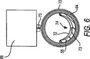
また、図5に示すフィルム巻き付け及び封止部63は、取入端部64aと取出端部64bとを有する形成パイプ64と、形成パイプ64の中央部上方に配置される縁部封止装置65を含んで成る。樹脂不浸透性フィルム材料67のロール66は、形成パイプ64の中に送られるにつれて、含浸された管55の周りに巻き付けられる。樹脂不浸透性フィルム材料67は、ロール66から一連の方向ローラー68a乃至68eへと供給され、フィルム67がローラー70a乃至70dを超えて形成パイプ64に送られる際に、1対の駆動ローラー69a及び69bによって引かれる。取出端部64bのデフレクター71は、フィルム67が縁部封止装置65に送られる前に、これを形成パイプ64の周りに導き、フィルム67を、それから外部へ延長している縁封止部73を有するチューブ72として形成する。形成パイプ64に沿って移動する不浸透性材料のチューブ72は、矢印Eで示す方向において、形成パイプ64の取入端部64aへと引き込まれ、そこでチューブ72は、形成パイプ64の内部及び含浸された管55の上に、引き続いて反転され、破線の矢印Fで示す反対方向に引かれる。 Further, the film winding and sealing portion 63 shown in FIG. 5 includes a forming
図6を参照すると、図5の線6−6に沿った封止装置65及び形成パイプ64の断面を示している。フィルム・チューブ72が形成パイプ64の外側を通過する際に、封止装置65はフィルム・チューブ72に縁封止部73を形成する。いったんチューブ72が反転されると、形成パイプ64の取出端部64bから引き出される縁封止部73は巻き付けられたウェット・アウト済みチューブ74の内部となる。尚、外側の不浸透性フィルム72の付加については、ウェット・アウトの前でも後でもよい。これがウェット・アウトの前である場合には、図3に示すように作成された管45が、図5の管形成アセンブリ63へと直接送られて、図7に断面で示すライナー74が得られる。この場合、樹脂含浸可能材料37は含浸されていない。 Referring to FIG. 6, a cross-section of sealing
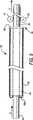
図8を参照すると、含浸された管55の周りに、外側の不浸透性チューブ81を巻き付けるための代替的な装置が、参照符号82で概略的に示されている。ここで管45は、図5のウェット・アウトタワー54に関連して記載したのと同じ方法で含浸されてもよく、その後、管55は、取入端部83a及び取出端部83bを有するスタッファー・パイプ83に送られる。尚、ここで、同一の要素については図5で用いた参照番号を用いている。 Referring to FIG. 8, an alternative device for wrapping the outer
可撓性をもった不浸透性チューブ81の供給部は、取入端部83a及び取出端部83bを有するスタッファー・パイプ83の外表面上に搭載される。樹脂タワー54を離れた含浸済みの管55は、スタッファー・パイプ83の取入端部83a内に送り込まれる。管55がスタッファー・パイプ83の取入端部83a内に入る際に、不浸透性チューブ81はスタッファー・パイプ83の外側から引き離され、取入端部83aの周りでスタッファー・パイプの内部へと反転され、それが取出端部83bから離れるにつれて、含浸済みの管55を包み込んでいく。これにより、内側の不浸透層38及び外側の不浸透性被覆81を有する完成したライナー86が形成される。外側の被覆81を有するチューブ86は、スタッファー・チューブ83の取出端部83bから矢印Fの方向へと、1組の駆動ローラー87及び88、又は牽引装置のようなそのほかの引張装置によって取り出される。押し出されたチューブが本実施形態で用いられる場合、外側の不浸透性被覆81には継ぎ目がない。このような方法でチューブ86を作成することによる唯一の制限は、スタッファー・チューブ83に配置可能な不浸透性チューブ81の長さである。約1,000フィート(約304.8メートル)の不浸透性チューブは、長さが約20フィート(約6.096メートル)のスタッファー・チューブ上に圧縮可能なことがわかっている。より長いスタッファー・チューブであれば、その上に、さらに長い不浸透性チューブを保有することができる。 The supply portion of the
図9は、スタッファー・チューブ83を出るときのライナー86の断面図である。図4との関係において説明したように、ライナー86は、樹脂吸収性材料37の内側管状部材を含み、該材料がテープ48で封止された不浸透性の内側被覆38を有する。スタッファー・チューブ83を出た後では、ライナー86が外側の管状ラップ部81を含んでいる。管状ラップ部81が前もって押し出されたチューブであるという事実から分かるように、外側のラップ部81は、図6及び図8と関連するような継ぎ目を有していない。 FIG. 9 is a cross-sectional view of
設置場所に置かれさえすれば、内側の不浸透層38と外側の不浸透性ラッピング72を有する含浸チューブ74又は86は、いつでも引込み及び膨張法による設置のための準備が整うことになる。この方法は、特許文献1に完全に記述されており、その内容は引用によって本明細書に組み込まれる。引込み及び膨張法により含浸ライナー74を設置する場合、内側に不浸透層38が存在するので、ライナーを膨張させるための反転ブラッダーを別途用いる必要はない。ポリプロピレンのような、内側の不浸透層38のための材料を適切に選択することによって、既設管路内の所定の位置でライナー74又は86に導入される蒸気を用いて、硬化させることができる。 As long as it is in place, the impregnated
ライナーが内側の不浸透層38をもたず、また外側不浸透性ラッピング72で包まれている場合に、上記特許文献2に記載されているような従来の反転方法を用いて設置を行うことができる。また、このようなライナーは、その内容が参照により本願に組み込まれる上記特許文献7及び特許文献8に記載されるような膨張ブラッダーを用いて設置してもよい。 When the liner does not have the inner
本願に記載の工法や装置は、内側及び外側の不浸透層をともに有する現場硬化型ライナーを作成するための、利便性のよい手段を提供する。つまり、図5に示す含浸タワーは、外側の不浸透層を付加する前に、内側の不浸透層を有する樹脂含浸可能な管を含浸させる方法を容易に提供する。 The methods and apparatus described herein provide a convenient means for creating an in-situ curable liner having both inner and outer impermeable layers. That is, the impregnation tower shown in FIG. 5 easily provides a method of impregnating a resin-impregnated tube having an inner impermeable layer before adding the outer impermeable layer.
図5に示される装置で作成される管は、連続して含浸を行いたいという要求に鑑み、煩雑な真空や高圧技術を用いた含浸の必要性を回避している。 In view of the demand for continuous impregnation, the tube produced by the apparatus shown in FIG. 5 avoids the need for impregnation using complicated vacuum and high pressure techniques.
したがって、上記の記載によって明らかとなった目的のなかでも、先に示した目的が効果的に得られることがわかる。また、本発明の精神と趣旨を逸脱しない範囲で、上記の工程の実施、記載の製品、先に示した構成に変更を加えてもよいことから、上記の記載に含まれ添付の図面に示される一切の事項は、例示的なものであって、限定的ではないものと解釈されることを意図している。 Therefore, it can be understood that the above-described purpose can be effectively obtained among the purposes clarified by the above description. In addition, modifications may be made to the implementation of the above steps, the described products, and the above-described configuration without departing from the spirit and spirit of the present invention. All matters discussed are intended to be illustrative and not limiting.
さらに、特許請求の範囲は、本明細書に述べられた本発明の一般的で具体的な特徴のすべてに及ぶことが意図され、そして、本発明の範囲のすべての記述は、言語の問題として、それらの間に収まると言えるであろうことも理解される。 Further, the claims are intended to cover all of the general and specific features of the invention described herein, and all statements in the scope of the invention are language issues. It is also understood that it will fit between them.
Claims (7)
Translated fromJapanese樹脂含浸可能材料の1層以上を含む第1の管状部材を1本提供し、
前記管状部材を、5〜14フィート(1.524〜4.2672メートル)の高さの樹脂含浸タワー内に供給し、前記樹脂含浸可能材料を樹脂で完全に含浸させ、
含浸された前記管状部材を前記タワーから引き出す方法であって、
含浸された前記管状部材の周りに樹脂不浸透性被覆を配置して外側の被覆とし、
含浸された前記管状部材の周りに樹脂不浸透性被覆を配置するステップにおいて、樹脂不浸透性材料の管を用意し、含浸された前記管状部材の周りに樹脂不浸透性材料の管を配置するステップを含み、
含浸された前記管状部材の周りに外側の被覆を配置するステップは、含浸された管状の材料が前記外側の被覆を通過する際に、樹脂不浸透性材料の管を、含浸された管状の材料の上へと反転させることを含む方法。In the method of impregnating the in-situ curable liner with resin,
Providing a first tubular member comprising one or more layers of resin-impregnable material;
Feeding said tubular memberinto a resin impregnated towerat a height of 5-14 feet (1.524-4.2672 meters), and fully impregnating said resin-impregnable material with resin;
A method of withdrawing the impregnated tubular member from the tower,
Placing a resin impervious coating around the impregnated tubular member to provide an outer coating;
In placing a resin impermeable coating about the impregnated the tubular member, providing a tube of resin impermeablematerials, the tube of resin impermeablematerials around the impregnated the tubular member Including the step of placing,
The step of placing an outer coating around the impregnated tubular member comprises the step of impregnating the tube of resin impervious material with the impregnated tubular material as the impregnated tubular material passes through the outer coating. A method comprising flipping over.
内側に樹脂不浸透層を有する,樹脂含浸可能材料の少なくとも1層の第1の管状部材を形成し,
1本の樹脂含浸可能材料であってその一面に不浸透層が接合された材料を提供し、
前記樹脂含浸可能材料を第1の方向に供給し、該材料を、外側に不浸透層を有する管状に形成し、
前記管状部材の長手方向の縁部同士を接合し、
外層が前記樹脂含浸可能材料となるように、前記管状部材を第2の反対方向においてそれ自身の中へと反転させ、そして、
引き続いて、前記一体化された不浸透層を内部に有する前記管状部材を取り出し、
前記第1の管状部材を、5〜14フィート(1.524〜4.2672メートル)の高さの樹脂含浸タワー内に供給し、前記樹脂含浸可能材料を樹脂で含浸させ、
含浸された前記管状部材を前記タワーから引き出し、
前記含浸された管状部材の周りに樹脂不浸透性の被覆を配置する方法。A method of making an in-situ cured liner having an impermeable layer on the inside,
Forming a first tubular member of at least one layer of resin-impregnable material having a resin impervious layer on the inside;
Providing a resin impregnable material having an impermeable layer bonded to one surface thereof;
Supplying the resin impregnable material in a first direction, forming the material into a tubular shape having an impermeable layer on the outside;
Joining the longitudinal edges of the tubular member together,
Inverting the tubular member into itself in a second opposite direction so that the outer layer is the resin-impregnable material; and
Subsequently, the tubular member having the integrated impermeable layer therein is taken out,
Feeding said first tubular memberinto a resin impregnated towerat a height of 5-14 feet (1.524-4.2672 meters); impregnating said resin-impregnable material with resin;
Pull the impregnated tubular member out of the tower;
Placing a resin impervious coating around the impregnated tubular member;
Applications Claiming Priority (2)
| Application Number | Priority Date | Filing Date | Title |
|---|---|---|---|
| US10/704,461US7238251B1 (en) | 2003-11-07 | 2003-11-07 | Method of preparing cured in place liner using resin impregnation tower |
| PCT/US2004/036629WO2005047758A1 (en) | 2003-11-07 | 2004-11-03 | Resin impregnation tower for cured in place liner |
Publications (3)
| Publication Number | Publication Date |
|---|---|
| JP2007516861A JP2007516861A (en) | 2007-06-28 |
| JP2007516861A5 JP2007516861A5 (en) | 2008-08-07 |
| JP4583380B2true JP4583380B2 (en) | 2010-11-17 |
Family
ID=34590742
Family Applications (1)
| Application Number | Title | Priority Date | Filing Date |
|---|---|---|---|
| JP2006538461AExpired - Fee RelatedJP4583380B2 (en) | 2003-11-07 | 2004-11-03 | Resin-impregnated tower for on-site curing type liners |
Country Status (19)
| Country | Link |
|---|---|
| US (4) | US7238251B1 (en) |
| EP (1) | EP1687560B1 (en) |
| JP (1) | JP4583380B2 (en) |
| KR (1) | KR101161455B1 (en) |
| CN (1) | CN1886618B (en) |
| AT (1) | ATE492767T1 (en) |
| AU (1) | AU2004288925C1 (en) |
| BR (1) | BRPI0416300B1 (en) |
| CA (1) | CA2544973C (en) |
| DE (2) | DE602004030712D1 (en) |
| DK (2) | DK1687560T3 (en) |
| ES (1) | ES2357771T3 (en) |
| IL (1) | IL175467A0 (en) |
| NO (1) | NO339436B1 (en) |
| NZ (1) | NZ547459A (en) |
| PL (2) | PL1687560T3 (en) |
| RU (1) | RU2358184C2 (en) |
| SG (1) | SG146655A1 (en) |
| WO (1) | WO2005047758A1 (en) |
Families Citing this family (16)
| Publication number | Priority date | Publication date | Assignee | Title |
|---|---|---|---|---|
| US7238251B1 (en)* | 2003-11-07 | 2007-07-03 | Insituform (Netherlands) B.V. | Method of preparing cured in place liner using resin impregnation tower |
| US7857932B1 (en)* | 2003-11-07 | 2010-12-28 | Ina Acquisition Corp. | Cured in place liner with everted outer impermeable layer and method of manufacture |
| US7517212B2 (en)* | 2004-07-01 | 2009-04-14 | Energy Mainteance Services Group I, Llc | Portable pipe repair system with electrically heated positioning member |
| US8273286B2 (en)* | 2007-09-10 | 2012-09-25 | Fram Jerry R | Positive pressure shear impregnator and wetout |
| BR112014010307A2 (en) | 2010-10-29 | 2017-08-08 | Long Pipes Pty Ltd | pipe construction |
| US20120199276A1 (en)* | 2011-02-07 | 2012-08-09 | Spiniello Companies | Tubular Liner for Underground Pipes and Method of Installing Tubular Liner |
| CN103649613A (en) | 2011-07-08 | 2014-03-19 | 陶氏环球技术有限责任公司 | Cured-in-place pipe rehabilitation process and such cured-in-place pipe |
| KR101318766B1 (en) | 2013-02-04 | 2013-10-16 | 한국라이텍개발(주) | Moving impregnation device of tube |
| US10563798B1 (en)* | 2014-04-07 | 2020-02-18 | Billy Don Hinkle | Compactable pipe T for poly irrigation tubing |
| WO2018160974A1 (en) | 2017-03-03 | 2018-09-07 | Insituform Technologies Llc | Curing device for curing a pipe liner |
| US11054069B1 (en) | 2017-04-25 | 2021-07-06 | Billy Don Hinkle | Compactable pipe T for poly irrigation tubing |
| US11173634B2 (en) | 2018-02-01 | 2021-11-16 | Ina Acquisition Corp | Electromagnetic radiation curable pipe liner and method of making and installing the same |
| US10704728B2 (en) | 2018-03-20 | 2020-07-07 | Ina Acquisition Corp. | Pipe liner and method of making same |
| JP7326666B2 (en) | 2018-04-23 | 2023-08-16 | アール. フラム,ジェリー | Application of Liquid Matrix Shear Pressure Impregnation Device |
| CN111495679B (en)* | 2020-04-28 | 2021-12-07 | 南兴装备股份有限公司 | Method for monitoring leakage condition of gluing mechanism of edge bonding machine |
| CN115890969B (en)* | 2022-09-01 | 2025-01-28 | 中国电建集团贵阳勘测设计研究院有限公司 | A light-curing hose prepreg process and prepreg device |
Family Cites Families (64)
| Publication number | Priority date | Publication date | Assignee | Title |
|---|---|---|---|---|
| US1508959A (en)* | 1921-07-22 | 1924-09-16 | Guyton & Cumfer Mfg Co | Saturator |
| US1845299A (en)* | 1929-01-25 | 1932-02-16 | Edward A Leonard | Saturation of sheets |
| US2125364A (en)* | 1930-02-18 | 1938-08-02 | Frederick A Waldron | Apparatus for drying and impregnating |
| US2428943A (en)* | 1943-01-09 | 1947-10-14 | Jr Walter A Plummer | Means for turning fabric tubes |
| US2565152A (en)* | 1946-10-30 | 1951-08-21 | Westinghouse Electric Corp | Process of impregnating a fibrous sheet with a phenolic resin |
| US2653432A (en)* | 1949-05-19 | 1953-09-29 | American Viscose Corp | Sausage stuffing machine |
| US2564725A (en)* | 1949-08-05 | 1951-08-21 | Ralph A Rusca | Apparatus for applying sizing and other coatings |
| US3223571A (en)* | 1962-04-30 | 1965-12-14 | Clemens F Straughan | Apparatus for applying a plastic film wrapping to a pipe line |
| US3533133A (en) | 1967-01-18 | 1970-10-13 | Stauffer Wacker Silicone Corp | Apparatus for the manufacture of plastic coated tubular articles |
| GB1340068A (en)* | 1970-09-22 | 1973-12-05 | Insituform Pipes & Structures | Lining of surfaces defining passageways |
| US3671298A (en)* | 1970-10-30 | 1972-06-20 | Westvaco Corp | Hydraulic system for controlling resin pickup |
| US3737261A (en) | 1971-02-16 | 1973-06-05 | Goldsworthy Eng Inc | Resin impregnating system |
| US3729359A (en)* | 1971-04-30 | 1973-04-24 | Wright Machinery Co Inc | Continuous tube sealer |
| US3889634A (en)* | 1971-06-17 | 1975-06-17 | Coats Ltd J & P | Method of and apparatus for producing liquid impregnated fibrous material |
| US4064211A (en) | 1972-12-08 | 1977-12-20 | Insituform (Pipes & Structures) Ltd. | Lining of passageways |
| GB1563424A (en) | 1974-01-25 | 1980-03-26 | Insituform Ltd | Lining of passageways |
| US4056457A (en)* | 1976-09-20 | 1977-11-01 | Rca Corporation | Method of depositing low stress hafnium thin films |
| GB1601234A (en) | 1978-02-08 | 1981-10-28 | Insituform Pipes & Structures | Materials for lining passageways |
| US4182262A (en) | 1978-07-05 | 1980-01-08 | Underground Surveys Corporation | Apparatus for impregnating a tube |
| US4366012A (en) | 1981-02-05 | 1982-12-28 | Insituform International Inc. | Impregnation process |
| US4456401A (en) | 1981-11-09 | 1984-06-26 | Finic, B.V. | Method and apparatus for relining underground passageway |
| GB8407706D0 (en) | 1984-03-24 | 1984-05-02 | Edgealpha Ltd | Lining pipelines in passageways |
| US4714095A (en) | 1985-06-10 | 1987-12-22 | Hans Muller | Method of salvaging a pipe conduit buried under ground |
| DE3546417A1 (en)* | 1985-12-31 | 1987-07-16 | Rolining Ag | METHOD AND DEVICE FOR RENOVATING IN PARTICULAR GROUND PIPELINES |
| US4940013A (en)* | 1986-11-18 | 1990-07-10 | Johannes Zimmer | Apparatus for coating fabric webs |
| US5230906A (en)* | 1986-11-24 | 1993-07-27 | Polytex Plastic Sa | Method of and apparatus for manufacturing fiber-reinforced plastics articles |
| EP0275060A1 (en)* | 1987-01-14 | 1988-07-20 | Insituform International Inc. | Improvements relating to the lining of pipelines and passageways |
| KR930001712B1 (en)* | 1988-11-18 | 1993-03-12 | 가부시기 가이샤 다구마 | Varnish impregnation method and apparatus |
| KR920701747A (en) | 1989-03-21 | 1992-08-12 | 원본미기재 | Improvements related to lining of pipes and passages |
| JPH03229A (en)* | 1989-05-26 | 1991-01-07 | Mazda Motor Corp | Molding apparatus for frp member |
| US4976290A (en) | 1989-06-12 | 1990-12-11 | Ozite Corporation | Tubular member having a liner |
| JP2736368B2 (en)* | 1990-04-10 | 1998-04-02 | 芦森工業株式会社 | Pipe liner and pipe line lining method |
| WO1991018234A1 (en) | 1990-05-18 | 1991-11-28 | Softlining Ag, Systems For Relining | Ready-for-use, sandwich mending tube for renovating the inside of damaged drain channels and process for producing the same |
| DE4113002A1 (en) | 1991-04-20 | 1992-10-22 | Teerbau Gmbh Strassenbau | METHOD FOR PRODUCING A LOCKED, LOCKABLE PLASTIC HOSE AND DEVICE THEREFOR |
| FR2683888B1 (en) | 1991-11-15 | 1993-12-31 | Chomarat Cie Ets Fils Auguste | COMPLEX STRUCTURE WHICH CAN BE USED IN PARTICULAR FOR REPAIRING CONDUITS AND METHOD FOR OBTAINING SUCH A STRUCTURE. |
| US5546992A (en) | 1994-01-18 | 1996-08-20 | Insituform (Netherlands) B.V. | Dual containment pipe rehabilitation system |
| RU2097196C1 (en) | 1995-03-06 | 1997-11-27 | Акционерное общество "Научно-производственное объединение "Стеклопластик" | Method of manufacturing sanitary tube for pipelines |
| US5653555A (en) | 1995-05-19 | 1997-08-05 | Inliner, U.S.A. | Multiple resin system for rehabilitating pipe |
| TW347455B (en)* | 1995-11-09 | 1998-12-11 | Link Pipe Inc | Conduit lining system and method of lining a conduit |
| RU2107216C1 (en)* | 1996-02-07 | 1998-03-20 | Владимир Григорьевич Загребельный | Method for applying coat on inner surface of pipeline |
| RU2111408C1 (en)* | 1996-05-22 | 1998-05-20 | Дрейцер Владимир Исаакович | Method of sanitation of inner surface of pipe line of heating system and hose for its realization |
| JP2927407B2 (en)* | 1996-06-06 | 1999-07-28 | 株式会社湘南合成樹脂製作所 | Pipe lining method |
| DE19637795C1 (en)* | 1996-09-17 | 1997-10-09 | Rothenberger Rohrsanierung Gmb | Reinforced multilayer tubing for pipelines lining |
| NL1004693C2 (en) | 1996-12-04 | 1998-06-05 | Syncoglas N V | Renovation or repair material. |
| WO1998031984A1 (en) | 1997-01-21 | 1998-07-23 | Neil Colin Hamilton | Thickness measuring apparatus |
| RU2125680C1 (en)* | 1997-02-04 | 1999-01-27 | Дрейцер Владимир Исаакович | Method of manufacture of coat for inner surface of pipe line (versions) |
| CN2283774Y (en)* | 1997-03-05 | 1998-06-10 | 曾立军 | Overturn lining flexible pipe for repair of pipe |
| JP2000127242A (en)* | 1998-10-26 | 2000-05-09 | Shonan Gosei Jushi Seisakusho:Kk | Manufacturing method of pipe lining material |
| DE19852690A1 (en) | 1998-11-16 | 2000-05-18 | Mueller Umwelttechnik | Method and device for the remediation of an old pipe run in the ground |
| US6270259B1 (en) | 1999-09-09 | 2001-08-07 | Emerson Electric Co. | Powdered metal sintered bearing with improved oil flow polygonal interior bore |
| AU2001251460A1 (en) | 2000-04-05 | 2001-10-23 | Flexfab Horizons International, Inc. | Fluorocarbon repair bladder |
| US6612340B1 (en) | 2000-06-30 | 2003-09-02 | Insituform (Netherlands) B.V. | Turnback protection for installation of cured in place liners |
| US6615875B2 (en) | 2000-08-30 | 2003-09-09 | Owens Corning Composites Sprl. | Liner for reinforcing a pipe and method of making the same |
| WO2002064351A2 (en) | 2001-02-15 | 2002-08-22 | Barloworld Robor (Proprietary)Ltd | Method and apparatus for lining an outer pipe with an inner pipe |
| US6708728B2 (en) | 2001-07-17 | 2004-03-23 | Insituform (Netherlands) B.V. | Installation of cured in place liners with air and steam and installation apparatus |
| US6539979B1 (en) | 2001-08-10 | 2003-04-01 | Insituform (Netherlands) B.V. | Pressurized bladder canister for installation of cured in place pipe |
| US20030113489A1 (en) | 2001-12-13 | 2003-06-19 | Smith E. Peter | Fiber reinforced cured in place liner for lining an existing conduit and method of manufacture |
| GB0203638D0 (en) | 2002-02-15 | 2002-04-03 | Lattice Intellectual Property | Method for lining a pipe or main |
| US6708729B1 (en)* | 2002-03-14 | 2004-03-23 | Instituform B.V. | Fiber reinforced composite liner for lining an existing conduit and method of manufacture |
| US6732763B2 (en)* | 2002-05-24 | 2004-05-11 | Lantor, Inc. | Stretch-resistant pipe liner |
| US7857932B1 (en)* | 2003-11-07 | 2010-12-28 | Ina Acquisition Corp. | Cured in place liner with everted outer impermeable layer and method of manufacture |
| US7238251B1 (en)* | 2003-11-07 | 2007-07-03 | Insituform (Netherlands) B.V. | Method of preparing cured in place liner using resin impregnation tower |
| US7261788B1 (en)* | 2003-11-07 | 2007-08-28 | Insitaform (Netherlands) B.V. | Preparation of cured in place liner with integral inner impermeable layer |
| DE602004030818D1 (en)* | 2003-11-07 | 2011-02-10 | Insituform Holdings Uk Ltd | LENGTH-STRENGTH, IN-SITU HARDENED CLOTHING |
- 2003
- 2003-11-07USUS10/704,461patent/US7238251B1/ennot_activeExpired - Lifetime
- 2004
- 2004-11-03RURU2006119932/06Apatent/RU2358184C2/ennot_activeIP Right Cessation
- 2004-11-03BRBRPI0416300Apatent/BRPI0416300B1/ennot_activeIP Right Cessation
- 2004-11-03ATAT04818618Tpatent/ATE492767T1/ennot_activeIP Right Cessation
- 2004-11-03WOPCT/US2004/036629patent/WO2005047758A1/enactiveApplication Filing
- 2004-11-03DEDE602004030712Tpatent/DE602004030712D1/ennot_activeExpired - Lifetime
- 2004-11-03NZNZ547459Apatent/NZ547459A/ennot_activeIP Right Cessation
- 2004-11-03PLPL04818618Tpatent/PL1687560T3/enunknown
- 2004-11-03CNCN200480035314XApatent/CN1886618B/ennot_activeExpired - Fee Related
- 2004-11-03AUAU2004288925Apatent/AU2004288925C1/ennot_activeCeased
- 2004-11-03EPEP04818618Apatent/EP1687560B1/ennot_activeExpired - Lifetime
- 2004-11-03PLPL116179Upatent/PL64199Y1/enunknown
- 2004-11-03JPJP2006538461Apatent/JP4583380B2/ennot_activeExpired - Fee Related
- 2004-11-03KRKR1020067011192Apatent/KR101161455B1/ennot_activeExpired - Fee Related
- 2004-11-03SGSG200806910-6Apatent/SG146655A1/enunknown
- 2004-11-03CACA2544973Apatent/CA2544973C/ennot_activeExpired - Fee Related
- 2004-11-03DEDE212004000054Upatent/DE212004000054U1/ennot_activeExpired - Lifetime
- 2004-11-03DKDK04818618.3Tpatent/DK1687560T3/enactive
- 2004-11-03ESES04818618Tpatent/ES2357771T3/ennot_activeExpired - Lifetime
- 2006
- 2006-02-15USUS11/354,720patent/US20060130753A1/ennot_activeAbandoned
- 2006-05-05DKDK200600127Upatent/DK200600127U3/ennot_activeIP Right Cessation
- 2006-05-07ILIL175467Apatent/IL175467A0/enunknown
- 2006-06-02NONO20062584Apatent/NO339436B1/ennot_activeIP Right Cessation
- 2007
- 2007-05-11USUS11/747,652patent/US20070204952A1/ennot_activeAbandoned
- 2008
- 2008-10-10USUS12/249,504patent/US20090038546A1/ennot_activeAbandoned
Also Published As
Similar Documents
| Publication | Publication Date | Title |
|---|---|---|
| JP4582550B2 (en) | Field curable liner with integrated inner impermeable layer and continuous manufacturing method | |
| JP4590413B2 (en) | Field curable liner with inverted outer impermeable layer and manufacturing method | |
| JP4833075B2 (en) | Installation method for in-situ curable liner with inner impermeable layer | |
| US20060130753A1 (en) | Resin impregnation tower for cured in place liner | |
| JP2007513800A (en) | Longitudinal reinforced in-situ liner | |
| MXPA06005050A (en) | Resin impregnation tower for cured in place liner | |
| HK1095621B (en) | Cured in place liner with integral inner impermeable layer and continuous method of manufacture | |
| MXPA06005053A (en) | Cured in place liner with integral inner impermeable layer and continuous method of manufacture | |
| MXPA06005048A (en) | Cured in place liner with everted outer impermeable layer and method of manufacture | |
| HK1095622B (en) | Resin impregnation tower for cured in place liner |
Legal Events
| Date | Code | Title | Description |
|---|---|---|---|
| A521 | Request for written amendment filed | Free format text:JAPANESE INTERMEDIATE CODE: A523 Effective date:20061213 | |
| RD04 | Notification of resignation of power of attorney | Free format text:JAPANESE INTERMEDIATE CODE: A7424 Effective date:20071003 | |
| RD02 | Notification of acceptance of power of attorney | Free format text:JAPANESE INTERMEDIATE CODE: A7422 Effective date:20071005 | |
| A521 | Request for written amendment filed | Free format text:JAPANESE INTERMEDIATE CODE: A523 Effective date:20071102 | |
| A621 | Written request for application examination | Free format text:JAPANESE INTERMEDIATE CODE: A621 Effective date:20071102 | |
| A521 | Request for written amendment filed | Free format text:JAPANESE INTERMEDIATE CODE: A523 Effective date:20080623 | |
| A621 | Written request for application examination | Free format text:JAPANESE INTERMEDIATE CODE: A621 Effective date:20071102 | |
| A977 | Report on retrieval | Free format text:JAPANESE INTERMEDIATE CODE: A971007 Effective date:20091217 | |
| A131 | Notification of reasons for refusal | Free format text:JAPANESE INTERMEDIATE CODE: A131 Effective date:20091222 | |
| A521 | Request for written amendment filed | Free format text:JAPANESE INTERMEDIATE CODE: A523 Effective date:20100318 | |
| A131 | Notification of reasons for refusal | Free format text:JAPANESE INTERMEDIATE CODE: A131 Effective date:20100414 | |
| A521 | Request for written amendment filed | Free format text:JAPANESE INTERMEDIATE CODE: A523 Effective date:20100709 | |
| TRDD | Decision of grant or rejection written | ||
| A01 | Written decision to grant a patent or to grant a registration (utility model) | Free format text:JAPANESE INTERMEDIATE CODE: A01 Effective date:20100804 | |
| A01 | Written decision to grant a patent or to grant a registration (utility model) | Free format text:JAPANESE INTERMEDIATE CODE: A01 | |
| A61 | First payment of annual fees (during grant procedure) | Free format text:JAPANESE INTERMEDIATE CODE: A61 Effective date:20100831 | |
| R150 | Certificate of patent or registration of utility model | Free format text:JAPANESE INTERMEDIATE CODE: R150 | |
| FPAY | Renewal fee payment (event date is renewal date of database) | Free format text:PAYMENT UNTIL: 20130910 Year of fee payment:3 | |
| R250 | Receipt of annual fees | Free format text:JAPANESE INTERMEDIATE CODE: R250 | |
| R250 | Receipt of annual fees | Free format text:JAPANESE INTERMEDIATE CODE: R250 | |
| R250 | Receipt of annual fees | Free format text:JAPANESE INTERMEDIATE CODE: R250 | |
| R250 | Receipt of annual fees | Free format text:JAPANESE INTERMEDIATE CODE: R250 | |
| R250 | Receipt of annual fees | Free format text:JAPANESE INTERMEDIATE CODE: R250 | |
| LAPS | Cancellation because of no payment of annual fees |