Movatterモバイル変換


[0]ホーム

URL:


JP4583156B2 - Collating machine paper receiving device - Google Patents

Collating machine paper receiving device
Download PDF

Info

Publication number
JP4583156B2
JP4583156B2JP2004361248AJP2004361248AJP4583156B2JP 4583156 B2JP4583156 B2JP 4583156B2JP 2004361248 AJP2004361248 AJP 2004361248AJP 2004361248 AJP2004361248 AJP 2004361248AJP 4583156 B2JP4583156 B2JP 4583156B2
Authority
JP
Japan
Prior art keywords
plate portion
collating machine
paper receiving
guide
paper
Prior art date
Legal status (The legal status is an assumption and is not a legal conclusion. Google has not performed a legal analysis and makes no representation as to the accuracy of the status listed.)
Expired - Lifetime
Application number
JP2004361248A
Other languages
Japanese (ja)
Other versions
JP2006168873A (en
Inventor
暢之 神戸
茂樹 高島
俊一郎 山田
Current Assignee (The listed assignees may be inaccurate. Google has not performed a legal analysis and makes no representation or warranty as to the accuracy of the list.)
Pressio Co Ltd
Original Assignee
Pressio Co Ltd
Priority date (The priority date is an assumption and is not a legal conclusion. Google has not performed a legal analysis and makes no representation as to the accuracy of the date listed.)
Filing date
Publication date
Application filed by Pressio Co LtdfiledCriticalPressio Co Ltd
Priority to JP2004361248ApriorityCriticalpatent/JP4583156B2/en
Publication of JP2006168873ApublicationCriticalpatent/JP2006168873A/en
Application grantedgrantedCritical
Publication of JP4583156B2publicationCriticalpatent/JP4583156B2/en
Anticipated expirationlegal-statusCritical
Expired - Lifetimelegal-statusCriticalCurrent

Links

Images

Landscapes

Description

Translated fromJapanese

この発明は、新聞折込広告丁合用などに用いられる丁合機において、丁合されて排出される紙を受取り集積する紙受装置に関する。  The present invention relates to a paper receiving apparatus for receiving and accumulating paper that is collated and discharged in a collating machine used for newspaper insert advertising collation and the like.

新聞折込広告用の数種類のちらしを一枚ずつ寄せ集めてセットにする丁合機としては、一般に上下に複数段にわたって設けた給紙台上のちらしを給紙装置により順次1枚ずつ送り出して縦送り装置により下方へ搬送しつつ重ね合わせ、最下段部で2つ折りにしたちらしの中にはさみ込んだちらしのセットを、紙排出口部より側方へ排出して紙受装置により集積する縦型の丁合機が用いられている。  As a collating machine that gathers several types of flyers for newspaper inserts one by one, generally, the flyers on the paper feed trays that are provided in multiple stages above and below are sent out one by one sequentially by the paper feeder. Vertical type that stacks while being conveyed downward by a feeding device, folded in half at the bottom step, and sandwiched in the shape, discharged to the side from the paper discharge port, and accumulated by the paper receiving device The collating machine is used.

そして上記紙受装置としては、丁合機の紙排出口(広告物繰出し部)の下部前方に紙受台(集積台)を設け、丁合機のフレームに基端部を揺動自在に支持した押え板や、上記フレームに基端部を固設した重錘付きの押えばねなどのガイドにより、上記紙排出口から前方に排出される丁合ずみのちらし束を案内して、上記紙受台上に集積させるものが用いられている(たとえば、特許文献1,2参照。)。
特開昭48−27517号公報(第2頁、第1図)実開平7−2355号公報(第1−2頁、図1)
As the paper receiving device, a paper receiving stand (stacking stand) is provided in front of the lower part of the paper discharge port (advertisement delivery portion) of the collating machine, and the base end portion is swingably supported on the frame of the collating machine. A guide plate such as a presser plate or a weighted presser spring with a base end fixed to the frame is used to guide the collimated flyer bundle discharged forward from the paper discharge port. What is integrated on a table is used (for example, refer toPatent Documents 1 and 2).
Japanese Patent Laid-Open No. 48-27517 (Page 2, Fig. 1) Japanese Utility Model Publication No. 7-2355 (page 1-2, FIG. 1)

ところが上記形式の紙受装置によると、図9(A)に示すように、複数枚のちらし81を二つ折りした折り紙(ちらし)82の中にはさみ込んだ丁合品であるちらし束80が、上記紙排出口から排出されたのち紙受台部において、図9(B)に示すように最上層紙である上側の折り紙82が前方へずれて、その前端部が上向きに膨出して折れ曲った上向折曲り部83が形成された形で、紙受台上に積層されることが多い。  However, according to the paper receiving apparatus of the above-described type, as shown in FIG. 9A, aleaflet bundle 80, which is a collated product obtained by sandwiching a plurality ofleaflets 81 intoleaflets 82, is formed on the paper. After the paper is ejected from the ejection port, theupper origami 82 as the uppermost layer of paper is shifted forward as shown in FIG. 9B, and the front end of theupper origami 82 bulges upward and bends. In many cases, thecounter-bending portion 83 is formed and laminated on a paper tray.

これは、図10(A)に示すように、紙受台90に固設した背板91の近傍部に、前端部が位置する形で集積されているちらし束のうちの最上層のちらし束80aの上に、図10(B)に示すように次のちらし束80がガイド92によりガイドされつつその先端部84が衝突すると、ちらし束80aの上側の折り紙82が上記先端部84により押されて鎖線85で示すように上方へ膨出し、この膨出部が前進する先端部84により前方に向ってしごかれる形で変形して、前記図9(B)に示す上向折曲り部83が形成されるものと推定される。なお図10において、最上層のちらし束80aより下側の各ちらし束80も、上記の上向折曲り部83が形成された状態で紙受台90上に積層されているのであるが、その図示は省略してある。  As shown in FIG. 10 (A), this is because the uppermost flyer bundle of the flyer bundles accumulated in the vicinity of theback plate 91 fixed to thepaper cradle 90 so that the front end portion is located. When thenext flyer bundle 80 is guided by theguide 92 and the leadingend 84 collides with the leadingend 84 as shown in FIG. 10B, theorigami 82 on the upper side of theflyer bundle 80a is pushed by the leadingend 84. As shown by achain line 85, the bulging portion bulges upward, and the bulging portion is deformed so as to be squeezed forward by the leadingend portion 84, and the upwardbent portion 83 shown in FIG. Is estimated to be formed. In FIG. 10, each of theflyer bundles 80 below theuppermost flyer bundle 80a is also laminated on thepaper tray 90 with theupward bent portion 83 formed therein. The illustration is omitted.

また通常、上記のガイド92は、巾20〜30mm程度の帯板を湾曲成形したものを、左右に間隔をおいて2本設けるだけなので、このガイド92で押えられていない部分においては、図10(C)に示すように鎖線85で示す膨出部は広範囲にわたって生じ、上向きに大きく突出した上向折曲り部83が形成されるのである。  In general, theguide 92 is formed by bending two strips having a width of about 20 to 30 mm and spaced apart from each other on the left and right sides. Therefore, in the portion not held by theguide 92, FIG. As shown to (C), the bulging part shown with thechain line 85 arises over a wide range, and the upwardbending part 83 which protruded largely upwards is formed.

上記の上向折曲り部83は、折り紙82の腰が弱い場合や、折り紙82の内面とこれに接するちらし81の表面との間の摩擦抵抗が小さい場合などに生じやすい。そして上記の上向折曲り部83を生じた状態のちらし束80は、紙受台90上から取上げて手作業あるいは自動式の折込装置を用いて新聞紙本体に折込む(挿入する)際に、上記の上向折曲り部83が邪魔で折込みの支障となったり、上向折曲り部83が破れて丁合品不良を生じやすく、また新聞へ折込んだ状態の外観も劣るなど、多くの問題点を有するものであった。  Theupward bent portion 83 is likely to occur when theorigami 82 is weak or when the frictional resistance between the inner surface of theorigami 82 and the surface of theleaf 81 in contact with theorigami 82 is small. Theflyer bundle 80 in the state in which theupward bent portion 83 is generated is picked up from thepaper tray 90 and folded (inserted) into the newspaper body using a manual operation or an automatic folding device. There are many problems such as the above-mentioned upwardbent portion 83 obstructing the folding, and the upwardbent portion 83 is easily broken to cause a defective product, and the appearance when folded into a newspaper is inferior. It was what had.

この発明は上記従来の問題点を解決しようとするもので、ちらし束を、その折り紙の前端部に上向折曲り部を生じることなく、二つ折りの折り紙ではさまれた良好な外観状態で集積させることができる丁合機の紙受装置を提供することを目的とする。  The present invention is intended to solve the above-mentioned conventional problems, and the flyer bundle is collected in a good appearance state sandwiched between two folded origami without generating an upward bent portion at the front end of the origami. An object of the present invention is to provide a paper receiving device for a collating machine that can be made to operate.

上記目的を達成するために、請求項1記載の丁合機の紙受装置は、丁合機の紙排出口部に配設された紙受台の前端部に複数枚の背板を間隔をおいて並設し、先端部が前記間隔部を貫通して前記背板の外側に延びる2本の帯板状のガイドの基端部を、丁合機のフレームに水平軸線のまわりに揺動自在に支持してなる丁合機の紙受装置において、前縁が前記背板の内側面近傍に位置し両側縁が平面視で前記2本のガイドの近傍位置に達する左右巾寸法を有し前記紙受台上の丁合品(ちらし束)の上面に載せられる平板部と、この平板部の後縁に連設され側面視で前記ガイドと交差して斜め後方上向きに延びる傾斜板部とをそなえた押え具を、前記背板に昇降自在に支持したことを特徴とする。  In order to achieve the above-mentioned object, the paper receiving device of the collating machine according toclaim 1 is configured such that a plurality of back plates are spaced at the front end portion of the paper receiving base disposed in the paper discharge port of the collating machine. The base end portions of two strip-shaped guides that are arranged side by side and that extend outside the back plate through the interval portion are swung around the horizontal axis on the frame of the collating machine In the paper receiving device of the collating machine that is freely supported, the front edge is located in the vicinity of the inner side surface of the back plate, and both side edges have a lateral width dimension that reaches the position in the vicinity of the two guides in plan view. A flat plate portion placed on the upper surface of the collated product (battery bundle) on the paper cradle and an inclined plate portion that is connected to the rear edge of the flat plate portion and that extends obliquely rearward and upward in a side view. The presser is supported by the back plate so as to be movable up and down.

この発明において、「前」側とは、丁合品排出口から排出される丁合品の進行方向側を称し、「後」側とはその反対側を称し、また「左右」とは後側から前側に向かう前後方向に対する左右方向を称するものとする。また背板の「外側」とは、上記丁合品の進行方向側、すなわち前側を称するものとし、背板の「内側」とはその反対側、すなわち上記丁合品の集積部側を称するものとする。  In this invention, the “front” side refers to the traveling direction side of the collated product discharged from the collated product discharge port, the “rear” side refers to the opposite side, and the “left and right” refers to the front side from the rear side. The left-right direction with respect to the front-rear direction is referred to. The “outside” of the back plate refers to the traveling direction side of the collated product, that is, the front side, and the “inside” of the back plate refers to the opposite side, that is, the accumulating portion side of the collated product.

請求項1記載の手段によれば、紙排出口から排出された丁合品であるちらし束は、2本のガイドにより案内されて斜め下向きに進行したのち、その先端部は、紙受台上に積層されているちらし束上に載置されている押え具の傾斜板部によって、該押え具の平板部の後縁部へと案内され、該後縁部付近で、積層されている最上層のちらし束に衝突するが、このちらし束の折り紙の上記衝突部より前側の部分は、平板部により広範囲にわたって下向きに押圧されているので、上記衝突による折り紙の上向きの膨出が抑制され、ちらし束はこの膨出部をしごくことによる上向折曲り部を形成させることなく背板部に達し積層される。  According to the means ofclaim 1, the flyer bundle, which is a collated product discharged from the paper discharge port, is guided obliquely by the two guides and proceeds obliquely downward, and its tip is laminated on the paper receiving tray. The uppermost flyer which is guided to the rear edge of the flat plate part of the presser by the inclined plate part of the presser placed on the flyer bundle and stacked near the rear edge. Collision with the bundle, but the front part of the origami of the flyer bundle is pressed downward over a wide range by the flat plate part, so that upward bulging of the origami due to the collision is suppressed, the flyer bundle The upper plate reaches the back plate portion and is laminated without forming an upward bent portion by squeezing the bulging portion.

請求項1記載の発明において、押え具を背板に昇降自在に支持するための昇降ガイドは、たとえば押え具の平板部に立設した2本のブラケットなどに取付けてもよいが、請求項2記載の発明のように、前記押え具が、前記平板部の前縁に連設され前記背板の内側面に沿って延びる上向板部をそなえ、この上向板部に、前記背板と係合する昇降ガイドを取付けた構成とすれば、押え具の構造が簡潔となる。  In the first aspect of the present invention, the lifting guide for supporting the presser on the back plate so as to be movable up and down may be attached to, for example, two brackets erected on the flat plate portion of the presser. As described in the invention described above, the presser includes an upward plate portion that is connected to the front edge of the flat plate portion and extends along the inner surface of the back plate, and the upward plate portion includes the back plate and the back plate portion. If it is set as the structure which attached the raising / lowering guide to engage, the structure of a presser will become simple.

また請求項3記載の丁合機の紙受装置は、丁合機の紙排出口部に配設された紙受台の前端部に複数枚の背板を間隔をおいて並設し、先端部が前記間隔部を貫通して前記背板の外側に延びる2本の帯板状のガイドの基端部を、丁合機のフレームに水平軸線のまわりに揺動自在に支持してなる丁合機の紙受装置において、前縁が前記背板の内側面近傍に位置し両側縁が平面視で前記2本のガイドの近傍位置に達する左右巾寸法を有し前記紙受台上の丁合品(ちらし束)の上面に載せられる平板部と、この平板部と同一平面上にあり前縁が前記背板の内側面近傍に位置し前記平板部の側方に前記ガイドを挟んで配置され連結部材を介して前記平板部に固定された副平板部と、前記平板部および副平板部の後縁にそれぞれ連設され側面視で前記ガイドと交差して斜め後方上向きに延びる傾斜板部とをそなえた押え具を、前記背板に昇降自在に支持したことを特徴とする。  Further, the paper receiving device of the collating machine according toclaim 3, wherein a plurality of back plates are arranged in parallel at a front end portion of the paper receiving base disposed at the paper discharge port portion of the collating machine, The base end of two strip-shaped guides that extend through the gap and extend outside the back plate are supported on the frame of the collating machine so as to be swingable around a horizontal axis. In the paper receiving device of the combined machine, the front edge is located in the vicinity of the inner side surface of the back plate, and both side edges have a lateral width that reaches the position in the vicinity of the two guides in plan view. A flat plate portion that is placed on the upper surface of the flyer bundle, and a front edge that is on the same plane as the flat plate portion and is located in the vicinity of the inner surface of the back plate with the guide interposed between the flat plate portions. A sub-plate portion fixed to the flat plate portion via a member, and the guides in a side view connected to rear edges of the flat plate portion and the sub-plate portion, respectively. Crossed presser equipped with an inclined plate portion extending obliquely rearwardly upward, characterized in that the vertically movable supported by the back plate.

請求項3記載の手段によれば、請求項1記載の発明と同じ押え具の平板部とこの平板部の後縁に連設された傾斜板部とによって、請求項1記載の発明と同じ作用効果が得られるのに加えて、ガイドを挟んで配置された副平板部とこの副平板部の後縁に連設された傾斜板部とによっても、これらの配置部において、ガイドに衝突したちらし束の副平板部の後縁部への案内と紙受台上の最上層のちらし束の折り紙の上向膨出の抑制作用が得られるので、請求項1記載の発明よりも左右巾の大きい広範囲にわたって、上向折曲り部の形成を防止できる。  According to the third aspect of the invention, the same function as that of the first aspect of the invention is achieved by the flat plate portion of the presser that is the same as that of the first aspect of the invention and the inclined plate portion that is connected to the rear edge of the flat plate portion. In addition to obtaining the effect, the sub-plate portion arranged with the guide interposed therebetween and the inclined plate portion connected to the rear edge of the sub-plate portion may cause the guide to collide with the guide in these arrangement portions. Since the action of guiding the bundle to the trailing edge of the sub-plate portion and the upward bulging of the origami of the uppermost flyer bundle on the paper cradle can be obtained, the lateral width is larger than that of the invention ofclaim 1 The formation of the upward bent portion can be prevented over a wide range.

請求項3記載の発明においても、押え具を背板に昇降自在に支持するための昇降ガイドは、たとえば押え具の平板部に立設した2本のブラケットなどに取付けてもよいが、請求項4記載の発明のように、前記連結部材が、前記平板部および副平板部の前縁に連設され前記背板の内側面に沿って左右方向に延びる上向板部から成り、この上向板部に、前記背板と係合する昇降ガイドを取付けた構成とすれば、上向板部が、主平板部と副平板部の連結部材と、昇降ガイドの支持部材とを兼ねることになり、押え具の構造が簡潔となる。  Also in the invention according toclaim 3, the lifting guide for supporting the presser so as to be raised and lowered on the back plate may be attached to, for example, two brackets erected on the flat plate portion of the presser. As in the invention according toclaim 4, the connecting member is composed of an upward plate portion that is provided continuously with the front edges of the flat plate portion and the sub flat plate portion and extends in the left-right direction along the inner side surface of the back plate. If the plate portion is provided with a lifting guide that engages with the back plate, the upward plate portion serves as a connecting member for the main flat plate portion and the sub flat plate portion, and a support member for the lifting guide. The structure of the presser is simplified.

この発明において、丁合品が衝突するガイドは、押え具に対して自由に上向きに揺動させてもよいが、請求項5記載の発明のように、前記押え具が、前記各ガイドの上側に小間隙をおいて位置する掛止片部をそなえ、丁合品の衝突により上向きに揺動する前記ガイドが前記掛止片部により掛止されるようにした構成とすれば、掛止片部により、ちらし束衝突時に2本のガイドのうちの一方が大きく上向きに揺動するのが抑制され、2本のガイドはほぼ同期状態で揺動するので、ちらし束は左右巾方向各部における前後のずれの少ない状態で押え具部へと案内される。  In this invention, the guide with which the collated product collides may be freely swung upward with respect to the presser. However, as in the invention described inclaim 5, the presser is small above each guide. If the latching piece portion is provided with a gap and the guide that swings upward due to the collision of the collated product is latched by the latching piece portion, Since one of the two guides is largely prevented from swinging upward when the bundle collides, the two guides swing in a substantially synchronized state, so that the flyer bundle has little front-rear shift in each part in the lateral width direction. In the state, it is guided to the presser part.

またこの発明において押え具は、その自重(背板に係合する昇降ガイド等を含む)のみにより、紙受台上のちらし束の上面を押圧するようにしてもよいが、請求項6記載の発明のように、前記押え具が、前記平板部上に取付けられるおもりをそなえている構成とすれば、押え具を軽量な材料で構成した場合でも、おもり重量の選定により適切な押圧力を得て最上層ちらし束の折り紙の膨出を抑制し上向折曲り部の形成を防止できるとともに、押え具が請求項5の掛止片部をそなえている場合には、大重量のちらし束衝突時等においても2本のガイドのうちの一方が上向きに大きく揺動するのを抑制できる。  Further, in the present invention, the presser may be configured to press the upper surface of the flyer bundle on the paper tray only by its own weight (including a lifting guide that engages with the back plate). As in the invention, if the presser has a weight that is mounted on the flat plate portion, even if the presser is made of a light material, an appropriate pressing force can be obtained by selecting the weight of the weight. In addition, it is possible to prevent the folding of the origami of the uppermost flyer bundle and prevent the upward bent portion from being formed, and when the presser has the latching piece portion ofclaim 5, the heavy flyer bundle collision Even at times, it is possible to prevent one of the two guides from largely swinging upward.

請求項1記載の発明によれば、紙排出口から排出されたちらし束の衝突時において、給紙台上に積層されている最上層のちらし束の折り紙の上向きの膨出が、押え具により抑制され、ちらし束はこの膨出部をしごくことによる上向折曲り部を形成させることなく背板部に達し積層されるので、ちらし束を、その折り紙の前端部に上向折曲り部を生じることなく、二つ折りの折り紙ではさまれた良好な外観状態で集積させることができる。  According to the first aspect of the present invention, the upward bulging of the origami of the topmost stack of bundles stacked on the sheet feeding table is caused by the presser at the time of collision of the bundle of sheets discharged from the paper discharge port. The flyer bundle reaches the back plate part without forming an upward bent part by squeezing the bulging part, and the flyer bundle is stacked on the front end part of the origami. Without being generated, it can be accumulated in a good appearance state sandwiched between two origami papers.

また上記の効果に加えて、請求項2記載の発明によれば、押え具の構造が簡潔となる。  In addition to the above effects, according to the invention described in claim 2, the structure of the presser is simplified.

請求項3記載の発明によれば、副平板部とこの副平板部の後縁に連設された傾斜板部との付加により、請求項1記載の発明よりも左右巾の大きい広範囲にわたって、さらに確実に上向折曲り部の形成を防止でき、ちらし束を一層良好な外観状態で集積させることができる。  According to the invention described inclaim 3, by adding the sub-plate portion and the inclined plate portion connected to the rear edge of the sub-plate portion, over a wide range having a larger left-right width than that of the invention described inclaim 1, The formation of the upward bent portion can be reliably prevented, and the flyer bundle can be accumulated in a better appearance state.

また、上記の請求項3記載の発明による効果に加えて、請求項4記載の発明によれば、上向板部が、主平板部と副平板部の連結部材と、昇降ガイドの支持部材とを兼ねることになり、押え具の構造が簡潔となる。  Moreover, in addition to the effect by invention of saidClaim 3, according to invention ofClaim 4, an upward board part is a connection member of a main flat plate part and a sub-plate part, A supporting member of a raising / lowering guide, As a result, the structure of the presser is simplified.

また上記の各効果に加えて、請求項5記載の発明によれば、ちらし束衝突時に2本のガイドはほぼ同期状態で揺動し、ちらし束は左右巾方向各部における前後のずれの少ない状態で押え具部へと案内されるので、ちらし束は前後のずれによる不揃いの少ない良好な状態で紙受台上に積層できる。  In addition to the above effects, according to the invention described inclaim 5, the two guides swing in a substantially synchronized state at the time of the collision of the flyer bundle, and the flyer bundle is in a state in which the front-rear shift in each part in the left-right width direction is small. Therefore, the flyer bundle can be laminated on the paper receiving tray in a good state with little unevenness due to forward / backward displacement.

また上記の各効果に加えて、請求項6記載の発明によれば、押え具を軽量な材料で構成した場合でも、おもり重量の選定により適切な押圧力を得て、上向折曲り部の形成を防止でき、また掛止片部をそなえている場合には、ちらし束が大重量の場合でも、2本のガイドのうちの一方が上向きに大きく揺動するのを抑制して、ちらし束を不揃いの少ない良好な状態で紙受台上に積層できる。  In addition to the above effects, according to the invention described inclaim 6, even when the presser is made of a light material, an appropriate pressing force can be obtained by selecting the weight weight, and the upward bent portion When it is possible to prevent the formation and the hooking piece portion is provided, even if the flyer bundle is heavy, it is possible to prevent one of the two guides from largely swinging upward, and the flyer bundle. Can be laminated on a paper tray in a good state with few irregularities.

以下図1〜図6に示す第1例により、この発明の実施の形態を説明する。先ず図1において、丁合機1は、前後両面が開口した箱状のケーシング2内に、給紙台3と、該給紙台の先端部付近に設けた給紙ローラ4と補助ローラ5および二重送り防止用の駒片(捌き板)6等から成る給紙装置7とを、前後に2列、上下に複数組並設し、各給紙台3上から給紙装置7により送出された丁合前のちらし81を、送りローラ8を経て、案内ローラ9を有する縦送り装置10により順次積層しながら下方へ送り、最下段に設けた折込装置11部において、最下段の給紙装置7から送りローラ8および後側ガイド12を経て前側ガイド13のストッパ部に当るまで送出された二つ折り用の折り紙(ちらし)82の中央部を、上下動する折込刃14により折り曲げ、この折り紙82に上方からのちらし81の一揃いを折込ローラ15によりはさみ込んで、この丁合状態のちらし束80を、搬出コンベヤ16により紙排出口17から矢印X方向に排出し、紙受装置20の紙受台21上に送出し集積するように構成されている。  Embodiments of the present invention will be described below with reference to a first example shown in FIGS. First, in FIG. 1, a collatingmachine 1 includes a sheet feeding table 3, asheet feeding roller 4 and anauxiliary roller 5 provided near the tip of the sheet feeding table, in a box-shaped casing 2 whose front and rear surfaces are open. A plurality of sets ofpaper feeders 7 made up of double-feed preventing pieces (spreading plates) 6 etc. are arranged in parallel in two rows in the front and rear, and sent from each paper feed table 3 by thepaper feeder 7. Theleaflet 81 before collation is sent downward through thefeed roller 8 while being sequentially stacked by thelongitudinal feed device 10 having theguide roller 9, and in thefolding device 11 provided at the lowermost level, the lowermostsheet feeding device 7 is folded by thefolding blade 14 moving up and down, and theorigami 82 is folded at the center portion of thefolding paper 82 that is fed through thefeed roller 8 and therear guide 12 until it hits the stopper portion of thefront guide 13. A set offlyers 81 from above 5, thecollapsible flyer bundle 80 is discharged from thepaper discharge port 17 in the direction of arrow X by the carry-outconveyor 16, sent onto thepaper receiving base 21 of thepaper receiving device 20 and accumulated. Has been.

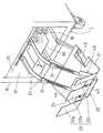
紙受装置20は、図2〜図6に示すように、丁合機1の紙排出口17の下部側方に紙受台21を設け、この紙受台21の前端部に3枚の背板22a〜22cを間隔23をおいて並設固着し、先端部が間隔23部を貫通して背板22(背板22a〜22cの総称)の外側に延びる帯板状の2本(一対)のガイド24,24の基部を、丁合機1のフレーム18に水平軸線25のまわりに揺動自在に支持するとともに、押え具40を背板22bに昇降自在に支持して成る。  As shown in FIGS. 2 to 6, thepaper receiving device 20 is provided with apaper receiving base 21 on the lower side of thepaper discharge port 17 of the collatingmachine 1, and three backs on the front end of thepaper receiving base 21. Two strips (a pair) in the form of strips extending in parallel to theplates 22a to 22c with aninterval 23, and extending to the outside of the back plate 22 (a general term for theback plates 22a to 22c) through theinterval 23 portions. The bases of theguides 24, 24 are supported on theframe 18 of the collatingmachine 1 so as to be swingable around thehorizontal axis 25, and thepresser 40 is supported on theback plate 22b so as to be raised and lowered.

上記紙受台21として、この例では図3に示すように、前部を軸26により基台27に傾動自在に支持され後部を圧縮ばね28により弾性支持された、傾動式の紙受台を用いている。29は基台27の後部と丁合機1のフレーム18を連結して基台27の位置ぎめをおこなう連結棒である。また21aは集積されたちらし束80の束を側方へ引出す時のための切欠部である。また上記のガイド24,24は、丁合機1の搬出コンベヤ16により矢印Xで示すように横向きに高速で排出される丁合ずみのちらし束80を案内して紙受台21上へ集積させるためのものであるが、この例では各ガイド24に、おもり31を取付位置変更自在に取付ける構成としてある。すなわち、各ガイド24に固設したアングル状の取付材32の側壁部に長手方向に穿設した長穴33を貫通する取付ねじ34をおもり31の側面にねじ込み、ガイド24に衝突するちらし束80の重量が大きい場合でも、ガイド24が水平軸線25を中心として過度にはね上らないようにおもり31の取付位置を調整し、確実にちらし束80を紙受台21に向って案内するようにしてある。  In this example, as shown in FIG. 3, thepaper cradle 21 is a tilting paper cradle having a front portion supported by ashaft 27 so as to be tiltable and a rear portion elastically supported by acompression spring 28. Used. A connectingrod 29 connects the rear portion of thebase 27 and theframe 18 of thecollator 1 to position thebase 27.Reference numeral 21a denotes a cut-out portion for pulling out the bundle of stackedbundles 80 sideways. Further, theguides 24, 24 guide thecolloidal flyer bundle 80 discharged at a high speed in the lateral direction by the carry-outconveyor 16 of thecollator 1 and accumulate it on thepaper tray 21. However, in this example, theweight 31 is attached to eachguide 24 so that the attachment position can be changed. That is, aflyer bundle 80 that is screwed into the side surface of theweight 31 and that collides with theguide 24 is screwed into the side face of theweight 31 through anelongated hole 33 drilled in the longitudinal direction in the side wall portion of the angle-shapedattachment member 32 fixed to eachguide 24. Even when the weight is large, the mounting position of theweight 31 is adjusted so that theguide 24 does not excessively rise around thehorizontal axis 25, and theflyer bundle 80 is surely guided toward thepaper tray 21. It is.

一方、押え具40は、図5に示すように両側縁が2本のガイド24,24の近傍位置に達する平板部41と、この平板部41の側方の1本のガイド24を挟んで配置された副平板部42の、背板22の内側面近傍に位置する各前縁部に、背板22の内側面に沿って左右に延びる上向板部43を連設して、平板部41と副平板部42を一体に連結し、平板部41と副平板部42の各後縁部41a,42aには、傾斜板部44,45を連設し、上向板部43に背板22bの両側辺部に係合するガイドローラ46,46を軸着して成り、このガイドローラ46によって押え具40は背板22bに昇降自在に支持されている。  On the other hand, as shown in FIG. 5, thepresser 40 is arranged with aflat plate portion 41 whose side edges reach the positions near the twoguides 24, 24 and asingle guide 24 on the side of theflat plate portion 41. Anupward plate portion 43 extending left and right along the inner side surface of the back plate 22 is connected to each front edge portion of thesub-plate portion 42 positioned in the vicinity of the inner side surface of the back plate 22, and theflat plate portion 41. And thesub-plate portion 42 are integrally connected to each other, inclinedplate portions 44 and 45 are connected to therear edge portions 41 a and 42 a of theplate portion 41 and thesub-plate portion 42, and theback plate 22 b is connected to theupward plate portion 43.Guide rollers 46 and 46 that are engaged with both sides of the shaft are pivotally attached, and thepresser 40 is supported on theback plate 22b by theguide rollers 46 so as to be movable up and down.

上記平板部41は、紙受台21上に集積される丁合品(ちらし束80)の上面に載せられるもので、副平板部42もこの平板部41と同一平面上にあり、上記丁合品の上面に載せられる。また傾斜板部44,45は、図5および図6に示すように、側面視でガイド24と交差して斜め後方上向きに延び、後端部はガイド24より上側位置に達している。また上向板部43には、図4に示すように、その下部を貫通するガイド24,24に対して小間隔gをおいて(下縁が)位置する掛止片部47,48を設けてある。  Theflat plate portion 41 is placed on the upper surface of the collated product (battery bundle 80) accumulated on thepaper tray 21, and the subflat plate portion 42 is also on the same plane as theflat plate portion 41, and is on the upper surface of the collated product. Can be placed. Further, as shown in FIGS. 5 and 6, theinclined plate portions 44 and 45 intersect with theguide 24 in the side view and extend obliquely rearward and upward, and the rear end portion reaches an upper position from theguide 24. Further, as shown in FIG. 4, theupward plate portion 43 is provided with latchingpiece portions 47 and 48 that are located at a small interval g (lower edge) with respect to theguides 24 and 24 penetrating the lower portion. It is.

またこの例では、上向板部43,平板部41,副平板部42,傾斜板部44,45の各部は、いずれも板厚0.5mm程度の薄い金属板で一体に成形されており、軽量であるのでその自重調整用に、おもり49を平板部41上に着脱自在としてある。おもり49は平板部41上に立設したピン50に嵌脱され、所望の重量のおもり49を選定して装着するようになっており、その重量選定については後述する。  In this example, each of theupward plate portion 43, theflat plate portion 41, the subflat plate portion 42, and theinclined plate portions 44 and 45 is integrally formed of a thin metal plate having a thickness of about 0.5 mm. Since it is lightweight, theweight 49 is detachable on theflat plate portion 41 for adjusting its own weight. Theweight 49 is fitted to and detached from apin 50 erected on theflat plate portion 41, and aweight 49 having a desired weight is selected and mounted. The weight selection will be described later.

上記構成の装置においては、丁合機1においてちらしの丁合をおこなえば、丁合されたちらし束80は紙排出口17から矢印X方向に排出され、2本のガイド24,24により案内されて斜め下向きに進行したのち、紙受台21上に載置されている押え具40の下側に進入し、紙受台21上に順次積層される。図6はこの積層中のちらし束80の挙動を示し、ガイド24,24により斜め下向きに案内されて矢印Y方向に進行したちらし束80の先端部84は、ガイド24の下端部寄りの位置において、紙受台21上に積層されているちらし束80上に載置されている押え具40の、ガイド24と斜め上向きに交差する傾斜板部44,45によって、平板部41,副平板部42の後縁部41a,42aへと案内され、この後縁部付近において最上層のちらし束80に衝突する。  In the apparatus configured as described above, when collating is performed in the collatingmachine 1, the collatedcollapsible bundle 80 is discharged from thepaper discharge port 17 in the direction of the arrow X and guided by the twoguides 24 and 24. After proceeding obliquely downward, it enters the lower side of thepresser 40 placed on thepaper receiving base 21 and is sequentially stacked on thepaper receiving base 21. FIG. 6 shows the behavior of thedust bundle 80 during the stacking, and thetip portion 84 of thetear bundle 80 is guided obliquely downward by theguides 24, 24 and proceeds in the direction of the arrow Y at a position near the lower end portion of theguide 24. Theflat plate portion 41 and the subflat plate portion 42 are formed by theinclined plate portions 44 and 45 of thepresser 40 placed on theflyer bundle 80 stacked on thepaper receiving base 21 and intersecting theguide 24 obliquely upward. Therear edge portions 41a and 42a are guided to collide with theuppermost flyer bundle 80 in the vicinity of the rear edge portion.

この最上層のちらし束80aの折り紙82の上記衝突部より前側の部分は、前後巾Sおよび左右巾V,W(図5参照)を有する平板部41,副平板部42によって広範囲にわたって下向きに押圧されているので、上記衝突による折り紙82の上向きの膨出が抑制され、ちらし束80はこの膨出部をしごくことによる上向折曲り部83(図9参照)を形成させることなく背板22部に達し積層され、上向折曲り部83の発生が防止されるのである。  The front portion of theorigami 82 of theuppermost flyer bundle 80a is pressed downward over a wide range by theflat plate portion 41 and the subflat plate portion 42 having front and rear widths S and left and right widths V and W (see FIG. 5). Therefore, the upward bulging of theorigami 82 due to the collision is suppressed, and theflyer bundle 80 does not form the upward bending portion 83 (see FIG. 9) by squeezing the bulging portion. Therefore, the upwardbent portion 83 is prevented from being generated.

また上記の紙排出口17から排出されるちらし束80がガイド24に衝突した際、この衝突により上向きに揺動する2本のガイド24,24の先端部(前端部)は、押え具40の上向板部43の掛止片部47,48に掛止され、2本のガイド24,24は1本のみが大きく上向きに揺動することなくほぼ同期状態で揺動するので、ちらし束80は左右巾各部における前後のずれの少ない(平面視で先端縁部が前後方向に対してほぼ直交する)状態で押え具40部へと案内され、前後のずれによる不揃いの少ない良好な状態で紙受台21上に積層されるのである。  Further, when theflyer bundle 80 discharged from thepaper discharge port 17 collides with theguide 24, the tip portions (front end portions) of the twoguides 24, 24 that swing upward due to the collision are formed on thepresser 40. Since only one of the twoguides 24, 24 is hooked on the hookingpiece portions 47, 48 of theupward plate portion 43 and swings in a substantially synchronized state without swinging upward, theflyer bundle 80 Is guided to thepresser 40 in a state where there is little front-rear shift in each part of the left and right width (the front end edge is substantially perpendicular to the front-rear direction in plan view), and the paper is in good condition with little unevenness due to front-rear shift It is laminated on thecradle 21.

この掛止片部47,48によるガイド24,24の揺動の均一化のための掛止片部による下向きの適正な掛止力、および前述の最上層のちらし束80aの折り紙82の膨出抑制のため、および背板22に衝突したちらし束80の過度の反撥・後退の防止のための、押え具40による下向きの適正な押圧力を得るために、この例ではちらし束80の重量等に応じて、おもり49の追加や交換をおこなうことにより、ちらし束80を不揃いの少ない良好な状態で紙受台21上に積層させることができる。なお押え具40を金属板製として、自重の異なる複数個の押え具40を取替使用する場合などは、おもり49は省略してもよい。  The downward appropriate hooking force by the hooking pieces for equalizing the swinging of theguides 24, 24 by the hookingpieces 47, 48, and the bulging of theorigami 82 of the above-mentioneduppermost flyer bundle 80a. In this example, the weight of theflyer bundle 80 is used in order to obtain a proper downward pressing force by thepresser 40 for suppressing and preventing excessive repulsion / retraction of thetearer bundle 80 that collides with the back plate 22. Accordingly, by adding or exchanging theweight 49, theflyer bundle 80 can be stacked on thepaper tray 21 in a favorable state with few irregularities. Theweight 49 may be omitted when thepresser 40 is made of a metal plate and a plurality ofpressers 40 having different weights are used.

この発明は上記の例に限定されるものではなく、たとえば押え具40の材質は、プラスチック製など上記以外のものとしてもよく、また丁合機1は、給紙装置7を一列そなえたものなど、上記以外の構成のものでもよい。また上記の例は3枚の背板22a〜22cが紙受台21に並設された場合について説明したが、背板が4枚以上あるいは2枚の場合などにもこの発明は適用でき、後者の場合、たとえば前記背板22cが欠落した場合の背板22bのように、隣合う背板がない側の「間隔部」は、背板(22b)の側縁部側方を称するものとする。さらに上記の例は傾動式の紙受台21を用いた場合について説明したが、この発明は固定式の紙受台を有する紙受装置にも適用できるものである。また上記のちらし束80は、ちらしと新聞増頁を丁合して得たちらし束や、丁合ずみのちらし束をさらに他のちらしと丁合して得た厚手のちらし束であってもよい。  The present invention is not limited to the above example. For example, the material of thepresser 40 may be other than the above such as plastic, and the collatingmachine 1 includes a single row ofpaper feeding devices 7. Other configurations than those described above may be used. In the above example, the case where the threeback plates 22a to 22c are arranged in parallel on thepaper receiving base 21 has been described. However, the present invention can be applied to the case where there are four or more back plates. In this case, for example, like theback plate 22b when theback plate 22c is missing, the "interval portion" on the side where there is no adjacent back plate refers to the side edge side of the back plate (22b). . Furthermore, although the above example has been described with respect to the case where the tilting typepaper receiving base 21 is used, the present invention can be applied to a paper receiving apparatus having a fixed type paper receiving base. Also, the above-mentionedflyer bundle 80 may be a thick flyer bundle obtained by collating a flyer and a newspaper extra page, or a thick flyer bundle obtained by collating a flyer bundle of collated paper with another flyer. Good.

また上記の例では、押え具40として副平板部42およびこれに連設した傾斜板部45をそなえたものを用いたので、ガイド24,24に衝突したちらし束80は傾斜板部44,45により左右巾の大きい広範囲にわたって各平板部の後縁部へと案内されるとともに、紙受台21上に積層された最上層のちらし束80a(の折り紙82)が左右巾の大きい広範囲にわたって押え具40により押圧されてその上向膨出が抑制されるので、折り紙82の上向折曲り部83の形成を特に確実に防止できるものであるが、たとえば背板22bがある程度広巾の場合などは、この副平板部42および傾斜板部45を省略して、図7に示す構成の押え具60とすることもできる。さらに掛止片部47,48を省略する場合は、図中鎖線61で示すように、上向板部43は平板部41および傾斜板部44と同寸(V)の左右巾とすればよい。なお図中、図2〜図6と同一または相当部分には同一符号を付して図示し、それらの詳細な説明は省略し、以下、他の例も同様とする。  Further, in the above example, since the holdingtool 40 having thesub-plate portion 42 and theinclined plate portion 45 connected thereto is used, thebundle 80 that collides with theguides 24, 24 becomes theinclined plate portions 44, 45. Is guided to the rear edge of each flat plate portion over a wide range with a large left-right width, and theuppermost flyer bundle 80a (origami 82) stacked on thepaper tray 21 is pressed over a wide range with a large left-right width. Since the upward bulging is suppressed by being pressed by 40, the formation of the upwardbent portion 83 of theorigami 82 can be particularly reliably prevented. For example, when theback plate 22b is somewhat wide, Thesub-plate portion 42 and theinclined plate portion 45 may be omitted to form thepresser 60 having the configuration shown in FIG. Further, when the latchingpiece portions 47 and 48 are omitted, as shown by a chain line 61 in the figure, theupward plate portion 43 may have the same width (V) as theflat plate portion 41 and theinclined plate portion 44. . In the figure, the same or corresponding parts as those in FIGS. 2 to 6 are denoted by the same reference numerals, detailed description thereof is omitted, and the same applies to other examples.

また上記各例では、平板部41と副平板部42を連結する上向板部43に、押え具40の昇降支持材(ガイドローラ46)を取付けた構成としたので、押え具40の構造を簡潔なものとすることができるが、図8に示す押え具70のように、平板部41に立設した2本のブラケット71,71にガイドローラ46,46を取付け、連結部材を兼ねた掛止片部48と、副平板部のない側の掛止片部47とを、平板部41および副平板部42に連続する1枚の屈曲板体で構成してもよい。また平板部41と副平板部42の連結部材やガイドローラ46の取付部材は、さらに別の構造のものとしてもよく、また押え具を背板22bに昇降自在に支持する部材としては、ガイドシューなど、ガイドローラ46以外の構造のものを用いてもよい。  In each of the above examples, since the lifting support member (guide roller 46) of thepresser 40 is attached to theupward plate 43 that connects theflat plate part 41 and the subflat plate part 42, the structure of thepresser 40 is as follows. Although it can be simplified, theguide rollers 46 and 46 are attached to the twobrackets 71 and 71 erected on theflat plate portion 41 like thepresser 70 shown in FIG. The retainingpiece 48 and the retainingpiece 47 on the side without the sub-plate portion may be configured by a single bent plate that is continuous with theflat plate portion 41 and thesub-plate portion 42. Further, the connecting member of theflat plate portion 41 and the subflat plate portion 42 and the mounting member of theguide roller 46 may be of another structure, and as a member for supporting the presser so as to be movable up and down on theback plate 22b, a guide shoe may be used. For example, a structure other than theguide roller 46 may be used.

この発明の実施の形態の一例を示す丁合機および紙受装置の縦断面図である。It is a longitudinal cross-sectional view of the collating machine and paper receiving apparatus which show an example of embodiment of this invention.図1の紙受装置の斜視図である。It is a perspective view of the paper receiving apparatus of FIG.図1のA部拡大縦断面図(図5におけるD−D線断面図)である。FIG. 6 is an enlarged vertical sectional view of a part A in FIG. 1 (a sectional view taken along the line DD in FIG. 5).図3の矢視B−B側面図である。It is an arrow BB side view of FIG.図3の矢視C−C平面図である。FIG. 4 is a plan view taken along the line CC in FIG. 3.ちらし束の集積動作を示す要部縦断面図(図5におけるE−E線断面図)である。It is a principal part longitudinal cross-sectional view (EE sectional view taken on the line in FIG. 5) which shows the integration | stacking operation | movement of a flyer bundle.この発明の実施の形態の他の例を示す押え具の斜視図である。It is a perspective view of the pressing tool which shows the other example of embodiment of this invention.この発明の実施の形態のさらに他の例を示す押え具の斜視図である。It is a perspective view of the pressing tool which shows the other example of embodiment of this invention.正常なちらし束と上向折曲り部の形成されたちらし束を示す斜視図である。It is a perspective view which shows the normal flicker bundle and the formation bundle in which the upward bending part is formed.従来の紙受装置におけるちらし束の上向折曲り部発生状況を示す要部縦断面図である。It is a principal part longitudinal cross-sectional view which shows the upward folding part generation | occurrence | production state of the flyer bundle in the conventional paper receiving apparatus.

符号の説明Explanation of symbols

1…丁合機、17…紙排出口、20…紙受装置、21…紙受台、22a…背板、22b…背板、22c…背板、23…間隔、24…ガイド、25…水平軸線、40…押え具、41…平板部、41a…後縁部、42…副平板部、42a…後縁部、43…上向板部、44…傾斜板部、45…傾斜板部、46…ガイドローラ、47…掛止片部、48…掛止片部、49…おもり、60…押え具、70…押え具、80…ちらし束。
DESCRIPTION OFSYMBOLS 1 ... Collating machine, 17 ... Paper discharge port, 20 ... Paper receiving apparatus, 21 ... Paper receiving stand, 22a ... Back board, 22b ... Back board, 22c ... Back board, 23 ... Space | interval, 24 ... Guide, 25 ... Horizontal Axis, 40 ... Presser, 41 ... Flat plate portion, 41a ... Rear edge portion, 42 ... Sub-plate portion, 42a ... Rear edge portion, 43 ... Upward plate portion, 44 ... Inclined plate portion, 45 ... Inclined plate portion, 46 ... guide roller, 47 ... latching piece, 48 ... latching piece, 49 ... weight, 60 ... presser, 70 ... presser, 80 ... flyer bundle.

Claims (6)

Translated fromJapanese
丁合機の紙排出口部に配設された紙受台の前端部に複数枚の背板を間隔をおいて並設し、先端部が前記間隔部を貫通して前記背板の外側に延びる2本の帯板状のガイドの基端部を、丁合機のフレームに水平軸線のまわりに揺動自在に支持してなる丁合機の紙受装置において、前縁が前記背板の内側面近傍に位置し両側縁が平面視で前記2本のガイドの近傍位置に達する左右巾寸法を有し前記紙受台上の丁合品の上面に載せられる平板部と、この平板部の後縁に連設され側面視で前記ガイドと交差して斜め後方上向きに延びる傾斜板部とをそなえた押え具を、前記背板に昇降自在に支持したことを特徴とする丁合機の紙受装置。  A plurality of back plates are juxtaposed at the front end portion of the paper receiving tray disposed in the paper discharge port portion of the collating machine, with the front end portion penetrating the gap portion and outside the back plate. In a paper receiving apparatus for a collating machine, in which a base end portion of two extending strip-shaped guides is supported on a frame of the collating machine so as to be swingable around a horizontal axis, the leading edge of the back plate is A flat plate portion that is located in the vicinity of the inner surface and has both lateral edges that reach the positions near the two guides in plan view and is placed on the upper surface of the collated product on the paper tray; and a rear edge of the flat plate portion A paper receiving device for a collating machine, characterized in that a presser provided with an inclined plate portion that is connected to the guide and extends obliquely rearward and upward and intersects with the guide in a side view is supported on the back plate so as to be movable up and down. . 前記押え具が、前記平板部の前縁に連設され前記背板の内側面に沿って延びる上向板部をそなえ、この上向板部に、前記背板と係合する昇降ガイドを取付けたことを特徴とする請求項1記載の丁合機の紙受装置。  The presser has an upward plate portion that is connected to the front edge of the flat plate portion and extends along the inner surface of the back plate, and a lifting guide that engages with the back plate is attached to the upward plate portion. 2. The paper receiving device for a collating machine according to claim 1, wherein the paper receiving device is a collating machine. 丁合機の紙排出口部に配設された紙受台の前端部に複数枚の背板を間隔をおいて並設し、先端部が前記間隔部を貫通して前記背板の外側に延びる2本の帯板状のガイドの基端部を、丁合機のフレームに水平軸線のまわりに揺動自在に支持してなる丁合機の紙受装置において、前縁が前記背板の内側面近傍に位置し両側縁が平面視で前記2本のガイドの近傍位置に達する左右巾寸法を有し前記紙受台上の丁合品の上面に載せられる平板部と、この平板部と同一平面上にあり前縁が前記背板の内側面近傍に位置し前記平板部の側方に前記ガイドを挟んで配置され連結部材を介して前記平板部に固定された副平板部と、前記平板部および副平板部の後縁にそれぞれ連設され側面視で前記ガイドと交差して斜め後方上向きに延びる傾斜板部とをそなえた押え具を、前記背板に昇降自在に支持したことを特徴とする丁合機の紙受装置。  A plurality of back plates are juxtaposed at the front end portion of the paper receiving tray disposed in the paper discharge port portion of the collating machine, with the front end portion penetrating the gap portion and outside the back plate. In a paper receiving apparatus for a collating machine, in which a base end portion of two extending strip-shaped guides is supported on a frame of the collating machine so as to be swingable around a horizontal axis, the leading edge of the back plate is A flat plate portion that is positioned in the vicinity of the inner surface and has both left and right side widths that reach the positions in the vicinity of the two guides in plan view, and is placed on the upper surface of the collated product on the paper tray, and is flush with the flat plate portion A sub-plate portion that is located on the inner surface of the back plate and is disposed on the side of the plate portion with the guide interposed therebetween and fixed to the plate portion via a connecting member; And an inclined plate portion that is connected to the rear edge of the sub-plate portion and extends obliquely rearward and upward, intersecting the guide in a side view. Kami受 apparatus collation machine the retainer, characterized in that the vertically movable supported by the back plate. 前記連結部材が、前記平板部および副平板部の前縁に連設され前記背板の内側面に沿って左右方向に延びる上向板部から成り、この上向板部に、前記背板と係合する昇降ガイドを取付けたことを特徴とする請求項3記載の丁合機の紙受装置。  The connecting member is composed of an upward plate portion that is connected to the front edge of the flat plate portion and the sub flat plate portion and extends in the left-right direction along the inner side surface of the back plate. 4. The paper receiving device for a collating machine according to claim 3, wherein a lifting guide for engagement is attached. 前記押え具が、前記各ガイドの上側に小間隙をおいて位置する掛止片部をそなえ、丁合品の衝突により上向きに揺動する前記ガイドが前記掛止片部により掛止されるようにしたことを特徴とする請求項1ないし請求項4のいずれかに記載の丁合機の紙受装置。  The presser has a latching piece portion located at a small gap on the upper side of each guide, and the guide that swings upward by the collision of a collated product is latched by the latching piece portion. The paper receiving device for a collating machine according to any one of claims 1 to 4, wherein the paper receiving device is a collating machine. 前記押え具が、前記平板部上に取付けられるおもりをそなえていることを特徴とする請求項1ないし請求項5のいずれかに記載の丁合機の紙受装置。  6. The paper receiving device for a collating machine according to claim 1, wherein the presser has a weight attached on the flat plate portion.
JP2004361248A2004-12-142004-12-14 Collating machine paper receiving deviceExpired - LifetimeJP4583156B2 (en)

Priority Applications (1)

Application NumberPriority DateFiling DateTitle
JP2004361248AJP4583156B2 (en)2004-12-142004-12-14 Collating machine paper receiving device

Applications Claiming Priority (1)

Application NumberPriority DateFiling DateTitle
JP2004361248AJP4583156B2 (en)2004-12-142004-12-14 Collating machine paper receiving device

Publications (2)

Publication NumberPublication Date
JP2006168873A JP2006168873A (en)2006-06-29
JP4583156B2true JP4583156B2 (en)2010-11-17

Family

ID=36670029

Family Applications (1)

Application NumberTitlePriority DateFiling Date
JP2004361248AExpired - LifetimeJP4583156B2 (en)2004-12-142004-12-14 Collating machine paper receiving device

Country Status (1)

CountryLink
JP (1)JP4583156B2 (en)

Families Citing this family (3)

* Cited by examiner, † Cited by third party
Publication numberPriority datePublication dateAssigneeTitle
JP5504424B2 (en)*2010-02-172014-05-28デュプロ精工株式会社 Bookbinding apparatus, bookbinding method and stacker apparatus
JP6461273B1 (en)*2017-09-292019-01-30株式会社プレッシオ Paper sheet stacking / conveying device
CN111591823B (en)*2020-05-072021-10-22北京地大彩印有限公司Page folding device of folding machine

Family Cites Families (8)

* Cited by examiner, † Cited by third party
Publication numberPriority datePublication dateAssigneeTitle
JPS5883354U (en)*1981-11-301983-06-06富士通株式会社 Stacker of sheet feeding device
JPS58161947U (en)*1982-04-261983-10-28大日本印刷株式会社 Sheet paper receiving device
JPH0275467U (en)*1988-11-251990-06-08
US5014977A (en)*1990-05-031991-05-14Xerox CorporationSheet stopping and lateral registration system
JPH072355U (en)*1993-06-151995-01-13デュプロ販売株式会社 Inserting advertising material carrier of advertising collator
JPH07172672A (en)*1993-12-211995-07-11Canon Inc Sheet alignment device
JP3372678B2 (en)*1994-11-142003-02-04ドーワワークス株式会社 Discharge guide bar lifting device
JP3432461B2 (en)*1999-08-232003-08-04ドーワワークス株式会社 Colling machine paper receiving device

Also Published As

Publication numberPublication date
JP2006168873A (en)2006-06-29

Similar Documents

PublicationPublication DateTitle
KR100342531B1 (en)Preventing device from slip-down of paper in inkjet printer
JP7072343B2 (en) Media ejector and image reader
US20100096801A1 (en)Paper sheet ejecting/collecting apparatus
JP4764840B2 (en) Paper discharge device
JP4583156B2 (en) Collating machine paper receiving device
JP2011111298A (en)Sheet feeder and image forming device including the same
KR100492083B1 (en)Paper cassette for image forming apparatus
US6634852B2 (en)Sheet understacking feeding mechanism
US6551052B2 (en)Sheet and stack feeding mechanism
JP2018177381A (en) Medium feeding device, recording device
JP2005320086A (en)Sheet feed device
EP1783076A3 (en)Shingle mode media item feed arrangement
JP3432461B2 (en) Colling machine paper receiving device
CN104044935B (en)Sheet bulk separator and use paper storehouse and the packing machine of this device
US6250628B1 (en)Arrangement for depositing sheets of a recording medium onto a stack
JP4022172B2 (en) Output stacking device
CN202337601U (en)Sheet feeding device
JP2008230845A (en) Paper feeder
JP2011143990A (en)Paper ejecting device
CN220033588U (en)Sheet cutting machine
JP5504424B2 (en) Bookbinding apparatus, bookbinding method and stacker apparatus
JP3250404B2 (en) Inkjet printer
JP4249067B2 (en) Advertising collation device
JP4297808B2 (en) Collating machine
JP2585651Y2 (en) Paper collet for signatures

Legal Events

DateCodeTitleDescription
A621Written request for application examination

Free format text:JAPANESE INTERMEDIATE CODE: A621

Effective date:20071022

A977Report on retrieval

Free format text:JAPANESE INTERMEDIATE CODE: A971007

Effective date:20100721

TRDDDecision of grant or rejection written
A01Written decision to grant a patent or to grant a registration (utility model)

Free format text:JAPANESE INTERMEDIATE CODE: A01

Effective date:20100817

A01Written decision to grant a patent or to grant a registration (utility model)

Free format text:JAPANESE INTERMEDIATE CODE: A01

A61First payment of annual fees (during grant procedure)

Free format text:JAPANESE INTERMEDIATE CODE: A61

Effective date:20100831

R150Certificate of patent or registration of utility model

Free format text:JAPANESE INTERMEDIATE CODE: R150

Ref document number:4583156

Country of ref document:JP

Free format text:JAPANESE INTERMEDIATE CODE: R150

FPAYRenewal fee payment (event date is renewal date of database)

Free format text:PAYMENT UNTIL: 20130910

Year of fee payment:3

R250Receipt of annual fees

Free format text:JAPANESE INTERMEDIATE CODE: R250

R250Receipt of annual fees

Free format text:JAPANESE INTERMEDIATE CODE: R250

R250Receipt of annual fees

Free format text:JAPANESE INTERMEDIATE CODE: R250

R250Receipt of annual fees

Free format text:JAPANESE INTERMEDIATE CODE: R250

R250Receipt of annual fees

Free format text:JAPANESE INTERMEDIATE CODE: R250

R250Receipt of annual fees

Free format text:JAPANESE INTERMEDIATE CODE: R250

R250Receipt of annual fees

Free format text:JAPANESE INTERMEDIATE CODE: R250

R250Receipt of annual fees

Free format text:JAPANESE INTERMEDIATE CODE: R250

EXPYCancellation because of completion of term

[8]ページ先頭

©2009-2025 Movatter.jp