Movatterモバイル変換


[0]ホーム

URL:


JP4582066B2 - Fixing method of droplet discharge head - Google Patents

Fixing method of droplet discharge head
Download PDF

Info

Publication number
JP4582066B2
JP4582066B2JP2006208867AJP2006208867AJP4582066B2JP 4582066 B2JP4582066 B2JP 4582066B2JP 2006208867 AJP2006208867 AJP 2006208867AJP 2006208867 AJP2006208867 AJP 2006208867AJP 4582066 B2JP4582066 B2JP 4582066B2
Authority
JP
Japan
Prior art keywords
head
droplet discharge
carriage
unit
discharge head
Prior art date
Legal status (The legal status is an assumption and is not a legal conclusion. Google has not performed a legal analysis and makes no representation as to the accuracy of the status listed.)
Expired - Fee Related
Application number
JP2006208867A
Other languages
Japanese (ja)
Other versions
JP2007090327A (en
Inventor
真一 中村
善昭 山田
Current Assignee (The listed assignees may be inaccurate. Google has not performed a legal analysis and makes no representation or warranty as to the accuracy of the list.)
Seiko Epson Corp
Original Assignee
Seiko Epson Corp
Priority date (The priority date is an assumption and is not a legal conclusion. Google has not performed a legal analysis and makes no representation as to the accuracy of the date listed.)
Filing date
Publication date
Application filed by Seiko Epson CorpfiledCriticalSeiko Epson Corp
Priority to JP2006208867ApriorityCriticalpatent/JP4582066B2/en
Publication of JP2007090327ApublicationCriticalpatent/JP2007090327A/en
Application grantedgrantedCritical
Publication of JP4582066B2publicationCriticalpatent/JP4582066B2/en
Anticipated expirationlegal-statusCritical
Expired - Fee Relatedlegal-statusCriticalCurrent

Links

Images

Landscapes

Description

Translated fromJapanese

本発明は、インクジェットヘッドに代表される液滴吐出ヘッドの複数個を、単一のキャリッジに組み付ける液滴吐出ヘッドの固定方法に関するものである。The present invention, a plurality of droplet ejection heads typified by inkjet heads, relatesto a fixedhow thedroplet discharge headthat assembled into a single carriage.

従来のプリンタ等では、複数(多数)の液滴吐出ヘッドを必要とする場合、各液滴吐出ヘッドを個々にヘッド保持部材に保持し、更にこれを単一のキャリッジに搭載して、複数の液滴吐出ヘッドを、ヘッド保持部材およびキャリッジと共にヘッドユニットとして扱うようにしている。
そして、液滴吐出ヘッドをヘッド保持部材に組み込む場合には、顕微鏡等を用いて人的に位置決めおよびねじ止め固定が行われる。また、ヘッド付きのヘッド保持部材をキャリッジに組み込む場合には、キャリッジにヘッド保持部材を位置決めするピン等を設けておいて、これにヘッド保持部材をセットし且つ固定するようにしている。
In a conventional printer or the like, when a plurality (large number) of droplet ejection heads are required, each droplet ejection head is individually held by a head holding member, and further mounted on a single carriage, The droplet discharge head is handled as a head unit together with a head holding member and a carriage.
When the droplet discharge head is incorporated into the head holding member, positioning and screwing are performed manually using a microscope or the like. When a head holding member with a head is incorporated in the carriage, a pin or the like for positioning the head holding member is provided on the carriage, and the head holding member is set and fixed to the pin.

ところで、この種の液滴吐出ヘッドは、そのノズル列から微小な液滴を精度良く且つ選択的に吐出することができるため、液晶表示装置や有機EL表示装置等のカラーフィルタの製造に応用可能であると共に、各種の電子デバイスや光デバイス等の製造装置への応用も期待されている。
このような応用技術を考慮すると、液滴吐出ヘッド自体の性能に加え、平面内におけるノズル(ノズル列)の位置精度(組付け精度)やその前提となるキャリッジの位置精度に、高い精度が要求される。また、吐出対象となる液体等によっては、液滴吐出ヘッドの寿命が短くなり、液滴吐出ヘッドの頻繁な交換も考慮する必要がある。
これらの点において、プリンタに搭載される従来の液滴吐出ヘッド(ヘッドユニット)では、各部の精度の累積が全体の精度を決定してしまうため、高い位置決め精度を安定に維持することには、おのずと限界が生ずる。また、手作業での組立では、作業が煩雑であり且つ信頼性が劣るものとなるおそれがある。
By the way, this type of droplet discharge head can accurately and selectively discharge minute droplets from the nozzle row, and can be applied to the manufacture of color filters such as liquid crystal display devices and organic EL display devices. In addition, it is expected to be applied to manufacturing apparatuses for various electronic devices and optical devices.
Considering such applied technology, high accuracy is required not only for the performance of the droplet discharge head itself, but also for the positional accuracy (assembly accuracy) of the nozzle (nozzle array) in the plane and the positional accuracy of the carriage that is the prerequisite. Is done. In addition, depending on the liquid to be ejected, the life of the droplet ejection head is shortened, and frequent replacement of the droplet ejection head needs to be considered.
In these respects, in the conventional droplet discharge head (head unit) mounted on the printer, since the accumulated accuracy of each part determines the overall accuracy, in order to stably maintain high positioning accuracy, Naturally there is a limit. Further, in manual assembly, the work is complicated and the reliability may be inferior.

本発明は、複数の液滴吐出ヘッドを、単一のキャリッジに安定に且つ精度良く組み付けることができる液滴吐出ヘッドの固定方法を提供することをその課題としている。The present invention, a plurality of droplet ejection heads, and its object is to providea fixinghow thedroplet discharge headthat can be assembled and stably and accurately on a single carriage.

本発明の液滴吐出ヘッドの固定方法は、ヘッド保持部材に搭載された液滴吐出ヘッドを、これが搭載されるキャリッジに位置決め状態で固定する液滴吐出ヘッドの固定方法であって、ヘッド保持部材を介して液滴吐出ヘッドをキャリッジに対し位置決め状態に保持するヘッド保持工程と、この状態でヘッド保持部材とキャリッジとの間に瞬間接着剤を注入する接着剤注入工程とを備えたことを特徴とする。
この場合、瞬間接着剤の注入は、ヘッド保持部材のキャリッジとの接触部を貫通して形成された接着剤注入孔を介して行われ、接着剤注入孔のキャリッジ側の端部は、面取りされていることが、好ましい。
The droplet discharge head fixing method of the present invention is a droplet discharge head fixing method for fixing a droplet discharge head mounted on a head holding member to a carriage on which the droplet discharge head is positioned. A head holding step for holding the droplet discharge head in a positioning state with respect to the carriage, and an adhesive injection step for injecting aninstantaneous adhesive between the head holding member and the carriage in this state. And
In this case, the instantaneous adhesive is injected through an adhesive injection hole formed through the contact portion of the head holding member with the carriage, and the end of the adhesive injection hole on the carriage side is chamfered. It is preferable.

この構成によれば、瞬間接着剤が凝固することで、ヘッド保持部材がキャリッジに位置決め状態のまま接着固定される。すなわち、ねじ止め等と異なり、外力を作用させることなく、ヘッド保持部材を介して液滴吐出ヘッドをキャリッジに固定することができる。したがって、固定作業における液滴吐出ヘッドの位置ずれを有効に防止することができる。
また、この構成によれば、接着剤注入孔の面取り部分により、この瞬間接着剤が注入されるヘッド保持部材とキャリッジとの接触部における毛細管現象が促進されるため、接触部に瞬間接着剤を確実且つ円滑に行き渡らせることができる。
According to this configuration, when theinstantaneous adhesive is solidified, the head holding member is bonded and fixed to the carriage while being positioned. That is, unlike the screwing or the like, the droplet discharge head can be fixed to the carriage via the head holding member without applying an external force. Accordingly, it is possible to effectively prevent the positional deviation of the droplet discharge head in the fixing operation.
In addition, according to this configuration, the chamfered portion of the adhesive injection hole promotes capillary action at the contact portion between the head holding member and the carriage to which the instantaneous adhesive is injected. It can be spread reliably and smoothly.

本発明の他の液滴吐出ヘッドの固定方法は、液滴吐出ヘッドをこれが搭載されるキャリッジに位置決め状態で固定する液滴吐出ヘッドの固定方法であって、液滴吐出ヘッドをキャリッジに対し位置決め状態に保持するヘッド保持工程と、
この状態で液滴吐出ヘッドとキャリッジとの間に瞬間接着剤を注入する接着剤注入工程とを備えたことを特徴とする。
Another droplet discharge head fixing method of the present invention is a droplet discharge head fixing method in which a droplet discharge head is fixed to a carriage on which the droplet discharge head is mounted, and the droplet discharge head is positioned with respect to the carriage. A head holding step for holding in a state;
In this state, an adhesive injection step of injecting aninstantaneous adhesive between the droplet discharge head and the carriage is provided.

この構成によれば、瞬間接着剤が凝固することで、液滴吐出ヘッドをキャリッジに位置決め状態のまま直接、接着固定することができ、固定作業における液滴吐出ヘッドの位置ずれを有効に防止することができる。According to this configuration, since theinstantaneous adhesive is solidified, the droplet discharge head can be directly bonded and fixed to the carriage while being positioned, and the positional displacement of the droplet discharge head in the fixing operation is effectively prevented. be able to.

本発明の液滴吐出ヘッドの固定方法によれば、外力を作用させることなく固定作業(固定動作)を行うことができるので、液滴吐出ヘッドをキャリッジに固定するときの位置ずれを確実に防止することができる。According tofixed methodof the droplet discharge head of the present invention, it is possible to carry out the fixing work without exerting external force (fixing operation), to ensure the positional deviation at the time of fixing the liquid droplet ejection head on the carriage Can be prevented.

以下、添付の図面を参照して、本発明の実施形態について説明する。インクジェットプリンタのインクジェットヘッド(液滴吐出ヘッド)は、微小なインク滴(液滴)をドット状に精度良く吐出することができることから、例えば液滴(吐出対象液)に特殊なインクや感光性の樹脂等を用いることにより、各種部品の製造分野への応用が期待されている。また、係る応用技術では、粘性の高い吐出対象液等の液滴吐出ヘッドの耐久性に大きな影響を与えるものも想定され、複数の液滴吐出ヘッドをキャリッジに精度良く組み込んだヘッドユニットを、随時供給可能とすることが必要となる。  Hereinafter, embodiments of the present invention will be described with reference to the accompanying drawings. An ink jet head (droplet discharge head) of an ink jet printer can accurately discharge minute ink droplets (droplets) in a dot shape. By using a resin or the like, application to the manufacturing field of various parts is expected. In addition, in such applied technology, it is assumed that there is a great influence on the durability of the droplet discharge head, such as a highly viscous discharge target liquid, and a head unit in which a plurality of droplet discharge heads are accurately incorporated in the carriage is installed as needed. It is necessary to enable supply.

本実施形態のヘッドユニットの組立装置は、例えば液晶表示装置等のフラットディスプレイに組み込まれるカラーフィルタの製造装置(以下、「描画装置」という)に併設され、これに随時ヘッドユニットを供給可能とするものである。この描画装置では、カラーフィルタのフィルタエレメントに、R.G.Bのフィルタ材料を液滴として吐出する複数の液滴吐出ヘッドを備えており、ヘッドユニットの組立装置は、この複数の液滴吐出ヘッドをキャリッジに精度良く組み込んでヘッドユニットを組み立て、これを描画装置に適宜供給できるようにしている。  The head unit assembly apparatus according to the present embodiment is provided in a color filter manufacturing apparatus (hereinafter referred to as a “drawing apparatus”) incorporated in a flat display such as a liquid crystal display apparatus, and the head unit can be supplied as needed. Is. In this drawing apparatus, R.D. G. A plurality of droplet discharge heads for discharging the filter material B as droplets are provided, and the head unit assembly apparatus assembles the head unit by accurately incorporating the plurality of droplet discharge heads into the carriage, and draws this. The device can be appropriately supplied.

この場合のヘッドユニットの組立手順は、先ず各液滴吐出ヘッドをヘッド保持部材に位置決め状態で個々に組み付け、これを単一のキャリッジに仮装着し、次いでキャリッジに対し各液滴吐出ヘッドを位置決めした後、仮固定し、最後に本固定するものである。そして、液滴吐出ヘッドのヘッド保持部材への組付け、キャリッジへの仮装着および本固定は、外工程として手作業により行われる一方、キャリッジに複数の液滴吐出ヘッドを位置決めし且つ仮固定する作業は、実施形態の組立装置で行われる。  The assembly procedure of the head unit in this case is as follows. First, each droplet discharge head is individually assembled in a positioning state on the head holding member, temporarily mounted on a single carriage, and then each droplet discharge head is positioned with respect to the carriage. After that, it is temporarily fixed and finally fixed. The assembly of the droplet discharge head to the head holding member, the temporary mounting to the carriage, and the main fixing are performed manually as an external process, while the plurality of droplet discharge heads are positioned and temporarily fixed to the carriage. The work is performed by the assembling apparatus of the embodiment.

そこで、本実施形態では、先ずこの組立装置で扱うヘッドユニットと、その構成要素である液滴吐出ヘッド、ヘッド保持部材およびキャリッジについて説明する。また、この説明に相前後して、ヘッドユニットと上記の描画装置との関係、治具を用いた液滴吐出ヘッドのヘッド保持部材への組付方法、およびヘッドユニットの位置決め基準となるアライメントマスクについて説明する。その後、ヘッドユニットの組立装置について詳細に説明することとする。そして、最後に、このヘッドユニットを、いわゆるフラットディスプレイの製造方法に適用した例について説明する。  Therefore, in the present embodiment, first, a head unit handled by the assembling apparatus, and a droplet discharge head, a head holding member, and a carriage which are constituent elements thereof will be described. Before and after this explanation, the relationship between the head unit and the above drawing apparatus, a method of assembling the droplet discharge head to the head holding member using a jig, and an alignment mask that serves as a positioning reference for the head unit Will be described. Thereafter, the head unit assembly apparatus will be described in detail. Finally, an example in which this head unit is applied to a so-called flat display manufacturing method will be described.

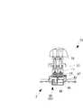
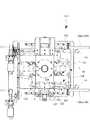
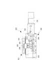
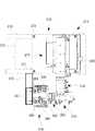
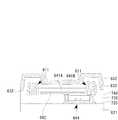
図1、図2および図3は、ヘッドユニットの構造図である。同図に示すように、ヘッドユニット1は、キャリッジ2と、キャリッジ2に搭載した複数個(12個)の液滴吐出ヘッド3と、各液滴吐出ヘッド3をキャリッジ2に個々に取り付けるための複数個(12個)のヘッド保持部材4とを備えている。12個の液滴吐出ヘッド3は、6個ずつ左右に二分され、主走査方向に対し所定の角度傾けて配設されている。また、各6個の液滴吐出ヘッド3は、副走査方向に対し相互に位置ずれして配設され、12個の液滴吐出ヘッド3の全吐出ノズル57(後述する)が副走査方向において連続する(一部重複)ようになっている。すなわち、実施形態のヘッド配列は、キャリッジ2上において、同一方向に傾けて配置した6個の液滴吐出ヘッド3を2列としてものであり、且つ各ヘッド列間において液滴吐出ヘッド3が相互に180°回転した配置となっている。もっとも、この配列パターンは一例であり、例えば、各ヘッド列における隣接する滴吐出ヘッド3同士を90°の角度を持って配置(隣接ヘッド同士が「ハ」字状)したり、各ヘッド列間における滴吐出ヘッド3を90°の角度を持って配置(列間ヘッド同士が「ハ」字状)したりすることは可能である。いずれにしても、12個の液滴吐出ヘッド3の全吐出ノズル57によるドットが副走査方向において連続していればよい。また、各種の基板に対し液滴吐出ヘッド3を専用部品とすれば、液滴吐出ヘッド3をあえて傾けてセットする必要は無く、千鳥状や階段状に配設すれば足りる。さらにいえば、所定長さのノズル列(ドット列)を構成できる限り、これを単一の液滴吐出ヘッド3で構成してもよいし複数の液滴吐出ヘッド3で構成してもよい。すなわち、液滴吐出ヘッド3の個数や列数、さらに配列パターンは任意である。  1, 2 and 3 are structural diagrams of the head unit. As shown in FIG. 1, thehead unit 1 includes acarriage 2, a plurality (12) ofdroplet discharge heads 3 mounted on thecarriage 2, and individualdroplet discharge heads 3 for attaching to thecarriage 2. A plurality of (12)head holding members 4 are provided. The twelvedroplet discharge heads 3 are divided into right and left parts by six and are inclined at a predetermined angle with respect to the main scanning direction. In addition, each of the sixdroplet discharge heads 3 is disposed so as to be displaced from each other in the sub-scanning direction, and all the discharge nozzles 57 (described later) of the twelvedroplet discharge heads 3 are arranged in the sub-scanning direction. It is continuous (partially duplicated). In other words, the head arrangement of the embodiment is such that sixdroplet discharge heads 3 arranged in the same direction on thecarriage 2 are arranged in two rows, and thedroplet discharge heads 3 are mutually connected between the head rows. The arrangement is rotated 180 °. However, this arrangement pattern is an example. For example, adjacentdroplet ejection heads 3 in each head row are arranged at an angle of 90 ° (adjacent heads are in a “C” shape), or between head rows. It is possible to arrange thedroplet discharge heads 3 at 90 ° with an angle of 90 ° (the inter-row heads are in a “C” shape). In any case, the dots formed by all thedischarge nozzles 57 of the twelvedroplet discharge heads 3 need only be continuous in the sub-scanning direction. If thedroplet discharge head 3 is a dedicated component for various substrates, it is not necessary to tilt thedroplet discharge head 3 and set it in a staggered or stepped manner. Furthermore, as long as a nozzle row (dot row) having a predetermined length can be formed, this may be constituted by a singledroplet discharge head 3 or a plurality ofdroplet discharge heads 3. That is, the number ofdroplet discharge heads 3, the number of columns, and the arrangement pattern are arbitrary.

キャリッジ2は、一部が切り欠かれた略方形の本体プレート11と、本体プレート11の長辺方向の中間位置に設けた左右一対の基準ピン12,12と、本体プレート11の両長辺部分に取り付けた左右一対の支持部材13,13と、各支持部材13の端部に設けた左右一対のハンドル14,14とを有している。左右のハンドル14,14は、例えば組み立てたヘッドユニット1を上記の描画装置Bに載せ込む場合に、ヘッドユニット1を手持ちするための部位となる。また、左右の支持部材13,13は、キャリッジ2を組立装置Aや描画装置Bのセット部に固定するときの部位となる(いずれも詳細は後述する)。  Thecarriage 2 includes a substantially rectangularmain body plate 11 with a part cut away, a pair of left andright reference pins 12 and 12 provided at intermediate positions in the long side direction of themain body plate 11, and both long side portions of themain body plate 11. And a pair of left andright handles 14 and 14 provided at the end of eachsupport member 13. The left andright handles 14 and 14 serve as parts for holding thehead unit 1 when the assembledhead unit 1 is placed on the drawing apparatus B, for example. The left andright support members 13 and 13 serve as parts for fixing thecarriage 2 to a set portion of the assembly apparatus A and the drawing apparatus B (both will be described later in detail).

さらに、キャリッジ2には、二分された液滴吐出ヘッド群3Sの上側に位置して、これら液滴吐出ヘッド3に接続される左右一対の配管接続アッセンブリ15,15および左右一対の配線接続アッセンブリ16,16が設けられている。各配管接続アッセンブリ15は、描画装置Bのフィルタ材料供給系に配管接続され、同様に各配線接続アッセンブリ16は、描画装置Bの制御系に配線接続されるようになっている。なお、図1は、一方(左側)の配管接続アッセンブリ15を省略して、描かれている。  Further, thecarriage 2 is positioned above the bisected dropletdischarge head group 3S, and a pair of left and rightpipe connection assemblies 15 and 15 and a pair of left and rightwiring connection assemblies 16 connected to thedroplet discharge head 3 are provided. , 16 are provided. Eachpipe connection assembly 15 is pipe-connected to the filter material supply system of the drawing apparatus B. Similarly, eachwiring connection assembly 16 is wired to the control system of the drawing apparatus B. In FIG. 1, one (left side)pipe connection assembly 15 is omitted.

本体プレート11は、ステンレス等の厚板で構成され、左右に各6個の液滴吐出ヘッド3を取り付けるための一対の装着開口18,18が形成されると共に、適宜位置に重量を軽減するための複数の抜き開口19が形成されている。各装着開口18は、6個の液滴吐出ヘッド3を取り付ける開口部位18aが連続したものであり、6個の液滴吐出ヘッド(液滴吐出ヘッド群3S)3の並びに倣って、その軸線が本体プレート11の軸線に対しわずかに傾いている。  Themain body plate 11 is made of a thick plate such as stainless steel, and is provided with a pair of mountingopenings 18 and 18 for mounting the six droplet discharge heads 3 on the left and right sides, and to reduce the weight at an appropriate position. A plurality ofapertures 19 are formed. Each mountingopening 18 is formed by a series of openingportions 18a to which six droplet discharge heads 3 are attached. The axis of the mountingopenings 18 follows the arrangement of the six droplet discharge heads (dropletdischarge head group 3S) 3. It is slightly inclined with respect to the axis of themain body plate 11.

各支持部材13は、厚手のステンレス板等で構成され、これを固定するための2つの固定孔(ばか孔)21,21および2つのボルト孔22,22が形成されると共に、これら固定孔21,21およびボルト孔22,22間に位置決め用のピンが挿入されるピン孔23が形成されている。詳細は後述するが、組立装置Aにヘッドユニット1をセットするときには、ピン孔23を用いて位置決めされると共に2つの固定孔21,21を用いてねじ止め固定され、同様に描画装置Bにヘッドユニット1をセットするときには、ピン孔23を用いて位置決めされると共に2つのボルト孔22,22を用いてねじ止め固定される。  Eachsupport member 13 is formed of a thick stainless plate or the like, and is formed with two fixing holes (fool holes) 21 and 21 and twobolt holes 22 and 22 for fixing the same, and these fixing holes 21. , 21 and bolt holes 22, 22 are formed withpin holes 23 into which positioning pins are inserted. Although details will be described later, when thehead unit 1 is set in the assembling apparatus A, thehead unit 1 is positioned using the pin holes 23 and screwed and fixed using the two fixingholes 21 and 21. When theunit 1 is set, theunit 1 is positioned using thepin hole 23 and screwed and fixed using the twobolt holes 22 and 22.

左右一対の基準ピン12,12は、画像認識を前提として、キャリッジ2をX軸、Y軸およびθ軸方向に位置決め(位置認識)するための基準となるものであり、本体プレート11の裏面に突出するように取り付けられている。図4に示すように、各基準ピン12は、円柱状のピン本体25と、ピン本体25の先端面の中央部に形成した凹状、具体的には孔状の基準マーク26とで構成されている。ピン本体25は、キャリッジ2に圧入するための基部圧入部27と、基部圧入部27に連なる胴部28と、胴部28の先端に突出形成したマーク形成部29とから成り、このマーク形成部29の先端面29aに基準マーク26が形成されている。  The pair of left and right reference pins 12 and 12 serve as a reference for positioning (position recognition) thecarriage 2 in the X-axis, Y-axis, and θ-axis directions on the premise of image recognition. It is attached to protrude. As shown in FIG. 4, eachreference pin 12 includes acylindrical pin body 25 and a concave, specifically hole-shapedreference mark 26 formed at the center of the tip surface of thepin body 25. Yes. Thepin body 25 includes a base press-fit portion 27 for press-fitting into thecarriage 2, abody portion 28 connected to the base press-fit portion 27, and amark forming portion 29 formed to protrude from the tip of thebody portion 28. Areference mark 26 is formed on thetip end surface 29 a of the 29.

マーク形成部29の先端面29aは鏡面加工されており、この先端面29aの中心位置に基準マーク26となる小孔が穿孔されている。小孔(基準マーク)26は、例えば直径0.3mm程度のものであり、基部圧入部27から胴部28にかけてその軸心部分に形成した軸心孔30に連通している。この場合、基準ピン12は、小孔26を穿孔した後、熱処理(イオン窒化)し、マーク形成部29の先端面29aを、鏡面仕上げして、形成される。鏡面仕上げの例としては、研磨工具と先端面29aの間に微細な砥粒を介在させて磨くラップ仕上げであるが、これに限定されるものではない。  Thetip surface 29a of themark forming portion 29 is mirror-finished, and a small hole that becomes thereference mark 26 is drilled at the center position of thetip surface 29a. The small hole (reference mark) 26 has a diameter of about 0.3 mm, for example, and communicates with theaxial hole 30 formed in the axial center portion from the base press-fittingportion 27 to thetrunk portion 28. In this case, thereference pin 12 is formed by drilling thesmall hole 26 and then heat-treating (ion nitriding), and mirror-finishing the front end surface 29 a of themark forming portion 29. An example of the mirror finish is a lapping finish in which fine abrasive grains are interposed between the polishing tool and thetip surface 29a, but is not limited thereto.

このように、簡単なプロセスによって先端面29aが白色で小孔の基準マーク26が暗色に認識カメラで撮像することができるため、キャリッジ2のアライメント精度を向上させることができる。なお、基準ピン12は、断面を円柱状として説明したが、楕円状でも、多角形状でも構わない。さらに、小孔の基準マーク26も、小孔に限定されるものではなく、充分なコントラストが得られるような溝を持つ凹形状であればよく、その凹の平面形状も円形に限定されるものではない。  As described above, since thefront end surface 29a is white and the smallhole reference mark 26 can be imaged by the recognition camera in a simple process, the alignment accuracy of thecarriage 2 can be improved. Although thereference pin 12 has been described as having a cylindrical cross section, it may be oval or polygonal. Further, thereference mark 26 of the small hole is not limited to the small hole, but may be a concave shape having a groove capable of obtaining sufficient contrast, and the planar shape of the concave is also limited to a circular shape. is not.

詳細は後述するが、組立装置Aおよび描画装置Bに搭載した認識カメラ353は、基準マーク26を形成した基準ピン12の先端面29aを、視野内に捕らえて画像認識(パターン認識)を行う。このため、認識カメラ353によるパターン認識では、鏡面仕上げの先端面29aが明色で、その先端面29aの略中央部に形成された凹形状の基準マーク26が暗色で認識され、十分なコントラストを持って基準マーク26が画像認識される。したがって、基準マーク26を精度良く認識することができ、認識ミスを確実に防止することができる。  Although details will be described later, therecognition camera 353 mounted on the assembling apparatus A and the drawing apparatus B performs image recognition (pattern recognition) by capturing thedistal end surface 29a of thereference pin 12 on which thereference mark 26 is formed within the field of view. For this reason, in the pattern recognition by therecognition camera 353, the mirror-finishedfront end surface 29a is recognized as a light color, and theconcave reference mark 26 formed in the substantially central portion of thefront end surface 29a is recognized as a dark color, and sufficient contrast is obtained. Thereference mark 26 is recognized as an image. Therefore, thereference mark 26 can be recognized with high accuracy, and recognition errors can be reliably prevented.

このようにして形成された基準ピン12は、その先端面29aを下向きにしてキャリッジ(本体プレート11)2に形成した取付用の孔部分に打ち込むようにして圧入される。キャリッジ2に圧入された基準ピン12は、キャリッジ2から突出した液滴吐出ヘッド3と略同一高さとなるように、本体プレート11の裏面から突出している。すなわち、基準ピン12の画像認識面となる先端面29aと、液滴吐出ヘッド3の画像認識面となるノズル形成面(図3参照)52とが、略同一平面内に位置するようになっている。  Thereference pin 12 thus formed is press-fitted so as to be driven into a mounting hole formed in the carriage (main body plate 11) 2 with itstip end surface 29a facing downward. Thereference pin 12 press-fitted into thecarriage 2 protrudes from the back surface of themain body plate 11 so as to have substantially the same height as thedroplet discharge head 3 protruding from thecarriage 2. That is, thetip end surface 29a serving as the image recognition surface of thereference pin 12 and the nozzle forming surface (see FIG. 3) 52 serving as the image recognition surface of thedroplet discharge head 3 are positioned in substantially the same plane. Yes.

これにより、認識カメラ353で、両基準ピン12,12に続いて各液滴吐出ヘッド3の吐出ノズル57を検出する場合に、その焦点位置を変更(認識カメラ353の上下動)する必要が無く、且つ画像認識のための認識カメラ353の相対的移動に際し、認識カメラ353が他の部品等に干渉するのを有効に防止することができる。なお、一対の基準ピン12,12は、本体プレート11の長辺方向の略中間位置に設けることが好ましいが、相互に離間している限り他の位置に設けてもよい。  Thus, when therecognition camera 353 detects the ejection nozzles 57 of the respective droplet ejection heads 3 following the both reference pins 12 and 12, there is no need to change the focal position (therecognition camera 353 moves up and down). In addition, when therecognition camera 353 is relatively moved for image recognition, therecognition camera 353 can be effectively prevented from interfering with other components. The pair of reference pins 12 and 12 are preferably provided at a substantially intermediate position in the long side direction of themain body plate 11, but may be provided at other positions as long as they are separated from each other.

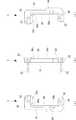
図1、図2および図3に示すように、左右のハンドル14,14は、重量のある(7kg程度)ヘッドユニット1を手持ちするためのものであり、各ハンドル14は、握り部分となるハンドル本体32と、ハンドル本体32の下端から直角に延びるアーム部33とで「L」字状に形成されている。ハンドル本体32は、その上端部が滑止め用の太径部34となっている。また、ハンドル本体32の外周面には、滑止め用のローレット加工が施されている。なお、本実施形態では、アヤ目のローレット加工を採用している(図2および図3参照)が、スジ目であってもよい。  As shown in FIGS. 1, 2, and 3, the left and right handles 14, 14 are for holding the heavy (about 7 kg)head unit 1, and each handle 14 is a handle serving as a grip portion. Themain body 32 and thearm portion 33 extending at a right angle from the lower end of the handlemain body 32 are formed in an “L” shape. Thehandle body 32 has a large-diameter portion 34 for preventing slip at the upper end. The outer peripheral surface of thehandle body 32 is knurled for slipping. In the present embodiment, the knurled knurling process is adopted (see FIGS. 2 and 3), but a streak may be used.

アーム部33は水平に延在し、その先端部でキャリッジ2の支持部材13に着座するようにしてねじ止めされている。すなわち、各ハンドル14は、キャリッジ2に着脱自在に取り付けられている。このように、左右のハンドル14,14は、キャリッジ(本体プレート11)2の長辺方向の端部からはみ出した位置、すなわち液滴吐出ヘッド3から離れた位置に、立ち上がるようにして設けられている。  Thearm portion 33 extends horizontally and is screwed so that the front end portion of thearm portion 33 is seated on thesupport member 13 of thecarriage 2. That is, each handle 14 is detachably attached to thecarriage 2. As described above, the left and right handles 14, 14 are provided so as to stand up at a position protruding from the end in the long side direction of the carriage (main body plate 11) 2, that is, a position away from thedroplet discharge head 3. Yes.

このため、両ハンドル14,14を把持してキャリッジ(ヘッドユニット1)2を持ち上げると、力のバランスにより、キャリッジ2は略水平姿勢を維持したまま持ち上げられることになる。また、運搬作業などにおいて、ハンドル14を握った手が液滴吐出ヘッド3に触れるなどの支障を生ずることがない。なお、詳細は後述するが、このハンドル14は、ヘッドユニット1の運搬は元より、ヘッドユニット1の描画装置Bへのセット作業に特に有用となる(詳細は後述する)。  For this reason, when the carriage (head unit 1) 2 is lifted by holding both thehandles 14, 14, thecarriage 2 is lifted while maintaining a substantially horizontal posture due to the balance of force. Further, there is no problem that the hand holding thehandle 14 touches thedroplet discharge head 3 during transportation work. Although details will be described later, thehandle 14 is particularly useful for setting thehead unit 1 to the drawing device B as well as transporting the head unit 1 (details will be described later).

各配管接続アッセンブリ15は、各液滴吐出ヘッド群3Sの上側に配設されており、本体プレート11の長辺方向の両端部に立設した一対のスペーサ36,36と、一対のスペーサ36,36間に渡した押さえプレート37と、押さえプレート37に搭載した6組の配管アダプタ38とで構成されている。6組の配管アダプタ38は、その下端のヘッド側接続部分をわずかに突出するようにして、それぞれ押さえプレート37に固着されている。  Eachpipe connection assembly 15 is disposed on the upper side of each dropletdischarge head group 3S, and includes a pair ofspacers 36 and 36 erected at both ends in the long side direction of themain body plate 11, and a pair ofspacers 36, Thepressing plate 37 is provided between 36 and six sets ofpiping adapters 38 mounted on thepressing plate 37. The six sets ofpipe adapters 38 are each fixed to the holdingplate 37 so that the head side connection portion at the lower end slightly protrudes.

詳細は後述するが、液滴吐出ヘッド3はいわゆる2連のものであり、6組の配管アダプタ38は、それぞれ2連の配管接続部材17を介して液滴吐出ヘッド3に接続される。すなわち、各液滴吐出ヘッド3に配管接続部材17を嵌合接続する一方、6組の配管アダプタ38を搭載した押さえプレート37を両スペーサ36,36にねじ止めすることで、6組の配管アダプタ38が、それぞれ配管接続部材17を介して液滴吐出ヘッド3に接続される。そして、各配管アダプタ38の流入側には、描画装置Bにセットする際にそのフィルタ材料供給系にワンタッチで配管接続される(詳細は後述する)。  Although details will be described later, the droplet discharge heads 3 are so-called two-units, and the six sets ofpipe adapters 38 are connected to the droplet discharge heads 3 via the two-unitpipe connection members 17 respectively. That is, thepipe connection member 17 is fitted and connected to eachdroplet discharge head 3, while the holdingplate 37 on which the six sets ofpipe adapters 38 are mounted is screwed to bothspacers 36 and 36, thereby providing six sets of pipe adapters. 38 are connected to thedroplet discharge head 3 via thepipe connecting member 17. Then, on the inflow side of eachpipe adapter 38, when the drawing adapter B is set, it is connected to the filter material supply system by one touch (details will be described later).

同様に、各配線接続アッセンブリ16は、キャリッジ2の左右の端部に立設した3個の屈曲支持部材40,40,40と、屈曲支持部材40の上端に固定したコネクタベース41と、コネクタベース41上に取り付けた配線コネクタ43付きの4つのヘッド中継基板42とで構成されている。4つのヘッド中継基板42は、それぞれフレキシブルフラットケーブル(図示省略)を介して、後述する各液滴吐出ヘッド3の2連のヘッド基板47に接続されている。そして、各ヘッド中継基板42には、描画装置Bにセットする際にその制御系ケーブルの配線プラグにより配線接続される(詳細は後述する)。  Similarly, eachwiring connection assembly 16 includes three bendingsupport members 40, 40, 40 erected on the left and right ends of thecarriage 2, aconnector base 41 fixed to the upper end of the bendingsupport member 40, and a connector base And fourhead relay boards 42 withwiring connectors 43 attached on 41. The fourhead relay substrates 42 are connected to twohead substrates 47 of eachdroplet discharge head 3 to be described later via flexible flat cables (not shown). Eachhead relay substrate 42 is connected by wiring with a wiring plug of its control system cable when set in the drawing apparatus B (details will be described later).

なお、図2にのみ示すように、このヘッドユニット1には更に、両配線接続アッセンブリ16を覆う中継基板カバー24が設けられている。中継基板カバー24は、各配線接続アッセンブリ16の側面から直上部を覆う一対の側面カバー24aと、一対の側面カバー24a間に渡した上面カバー24bとで構成されており、このうち上面カバー24bは、ヘッドユニット1を描画装置Bにセットした後に取り付けるようになっている。また、詳細は後述するが、ヘッドユニット1を組立装置Aにセットする段階では、描画装置Bにセットする場合と異なり、中継基板カバー24は元より両アッセンブリ15,16も組み付けておかないものとする。  As shown only in FIG. 2, thehead unit 1 is further provided with arelay board cover 24 that covers both thewiring connection assemblies 16. Therelay board cover 24 is composed of a pair of side covers 24a that cover the upper part from the side surface of eachwiring connection assembly 16, and anupper surface cover 24b that is passed between the pair of side surface covers 24a. Thehead unit 1 is attached after being set in the drawing apparatus B. Although details will be described later, when thehead unit 1 is set in the assembling apparatus A, unlike the case where it is set in the drawing apparatus B, therelay board cover 24 does not have bothassemblies 15 and 16 assembled. To do.

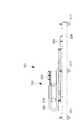
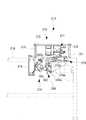
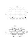
次に、図5ないし図8を用いて液滴吐出ヘッド3について説明する。この液滴吐出ヘッド3は、いわゆる2連のものであり、2連の接続針46を有する液体導入部45と、液体導入部45の側方に連なる2連のヘッド基板47と、液体導入部45に下方に連なる2連のポンプ部48と、ポンプ部48に連なるノズル形成プレート49とを備えている。液体導入部45には、上記の配管接続部材17が接続され、ヘッド基板47には、上記のフレキシブルフラットケーブルが接続されている。一方、このポンプ部48とノズル形成プレート49とにより、キャリッジ2の裏面側に突出する方形のヘッド本体50が構成されている。また、ノズル形成プレート49のノズル形成面52には、2列のノズル列53,53が形成されている(図6参照)。  Next, thedroplet discharge head 3 will be described with reference to FIGS. Thedroplet discharge head 3 is a so-called double-unit, which is aliquid introduction unit 45 having two connection needles 46, adouble head substrate 47 continuous to the side of theliquid introduction unit 45, and a liquid introduction unit. 45 includes twopump portions 48 that continue downward, and anozzle forming plate 49 that continues to thepump portion 48. Thepipe connection member 17 is connected to theliquid introduction part 45, and the flexible flat cable is connected to thehead substrate 47. On the other hand, thepump portion 48 and thenozzle forming plate 49 constitute a rectangular headmain body 50 that protrudes toward the back side of thecarriage 2. Also, twonozzle rows 53, 53 are formed on thenozzle forming surface 52 of the nozzle forming plate 49 (see FIG. 6).

図6および図7に示すように、ポンプ部48は、ノズル数に対応する圧力室55と圧電素子56とを有し、各圧力室55は、対応する吐出ノズル57に連通している。また、ポンプ部48の基部側、すなわちヘッド本体50の基部側は、液体導入部45を受けるべく方形フランジ状に形成され、このフランジ部58には、液滴吐出ヘッド3をヘッド保持部材4に固定する小ねじ用の一対のねじ孔(雌ねじ)59,59が形成されている。この一対のねじ孔59,59は、両長辺部分に位置し、且つノズル形成面52の中心に対し点対称となるように配設されている。詳細は後述するが、ヘッド保持部材4を貫通してフランジ部58に螺合した2本の小ねじ73,73により、液滴吐出ヘッド3がヘッド保持部材4に固定される(図9参照)。  As shown in FIGS. 6 and 7, thepump unit 48 includespressure chambers 55 andpiezoelectric elements 56 corresponding to the number of nozzles, and eachpressure chamber 55 communicates with acorresponding discharge nozzle 57. Further, the base side of thepump unit 48, that is, the base side of the headmain body 50 is formed in a square flange shape to receive theliquid introduction unit 45, and thedroplet discharge head 3 is attached to thehead holding member 4 in thisflange unit 58. A pair of screw holes (female screws) 59, 59 for a small screw to be fixed are formed. The pair of screw holes 59, 59 are located at both long side portions and are disposed so as to be point symmetric with respect to the center of thenozzle forming surface 52. Although details will be described later, thedroplet discharge head 3 is fixed to thehead holding member 4 by twosmall screws 73 and 73 that pass through thehead holding member 4 and are screwed into the flange portion 58 (see FIG. 9). .

ノズル形成プレート49は、ステンレス板等で形成され、ポンプ部48の吐出側端面(液滴吐出面)に接着されている。より具体的には、図6および図7(a)に模式的に示すように、ポンプ部48は、上記の圧電素子56を収容した機構部48aと、樹脂フィルム48bを介して、ノズル形成プレート49と共にこの機構部48aに接合されるシリコンキャビティ48cとを有している。すなわち、ノズル形成プレート49は、シリコンキャビティ48cに接着され、この状態で樹脂フィルム48bを介して、機構部48aの接合面48dに接合され、上記の圧力室55を構成している。したがって、ヘッド本体50において組立方法を勘案すると、上記の樹脂フィルム48b、シリコンキャビティ48cおよびノズル形成プレート(後述するメッキ層49aを含む)49は、ポンプ部48の機構部48aに対し、圧力室組立体60を構成している。そして、機構部48aの接合面48dは、長方形に形成される一方、ノズル形成プレート49を含む圧力室組立体60は、これより幾分小さい相似形に形成されており、圧力室組立体60は、接合面48dと略同心となるように重ねて接合されている。  Thenozzle forming plate 49 is formed of a stainless steel plate or the like, and is bonded to the discharge side end surface (droplet discharge surface) of thepump unit 48. More specifically, as schematically shown in FIGS. 6 and 7A, thepump portion 48 includes a nozzle forming plate via amechanism portion 48 a containing thepiezoelectric element 56 and aresin film 48 b. 49 and asilicon cavity 48c joined to themechanism 48a. That is, thenozzle forming plate 49 is bonded to thesilicon cavity 48c, and in this state, is bonded to the bonding surface 48d of themechanism portion 48a via theresin film 48b to constitute thepressure chamber 55 described above. Therefore, in consideration of the assembly method in the headmain body 50, theresin film 48b, thesilicon cavity 48c, and the nozzle forming plate (including a platedlayer 49a described later) 49 are arranged in the pressure chamber assembly with respect to themechanism portion 48a of thepump portion 48. A solid 60 is formed. The joint surface 48d of themechanism portion 48a is formed in a rectangular shape, while thepressure chamber assembly 60 including thenozzle forming plate 49 is formed in a somewhat smaller similar shape. , And are joined so as to be substantially concentric with the joining surface 48d.

このため、圧力室組立体60の四周と機構部48aの接合面48dの四周縁部との間には、四周に亘って接合のためのクリアランスとしての段部61が構成され、この段部61には樹脂62がモールドされている。すなわち、接合面48dの端縁(周縁部)と圧力室組立体60の端面(側面部)とで構成される段部61は、これを埋めるように樹脂62でモールドされている。したがって、ヘッド本体50の下端は、この樹脂62により四周が面取りされた形態になっている。  For this reason, between the four circumferences of thepressure chamber assembly 60 and the four peripheral edges of the joining surface 48d of themechanism portion 48a, astep portion 61 is formed as a clearance for joining over the four circumferences. Aresin 62 is molded on the substrate. That is, thestep portion 61 constituted by the end edge (peripheral portion) of the joint surface 48d and the end surface (side surface portion) of thepressure chamber assembly 60 is molded with theresin 62 so as to fill thestep portion 61. Therefore, the lower end of the headmain body 50 has a shape in which the four circumferences are chamfered by theresin 62.

詳細は後述するが、この樹脂62によるモールドにより、ワイピングの際にヘッド本体50がワイピングシート131につかえるのを防止している。この場合、液滴吐出ヘッド3は水平面内において幾分傾いてキャリッジ2に保持されているものの、ヘッド本体50に対しワイピングシート131は、X軸方向から拭取り動作する(図17参照)。したがって、上記の四周に亘るモールドの樹脂62は、最低限拭取りを開始する側の長辺部分にのみ、或いは両長辺部分にのみに設けられていればよい。また、後述する面取り加工でも同様である。なお、図7(b)に示すように、樹脂62をノズル形成プレート49から前方に幾分突出(図示のt寸法)するようにモールドし、樹脂62に、吐出ノズル57を保護するプロテクタの機能を持たせることも可能である。また、図7(c)に示すように、機構部48aの接合面48dと圧力室組立体60とを同一形状とし、樹脂62のモールドに代えて、圧力室組立体60の端縁を面取り加工するようにしてもよい。  Although details will be described later, the molding with theresin 62 prevents thehead body 50 from being held by the wipingsheet 131 during wiping. In this case, although thedroplet discharge head 3 is held by thecarriage 2 with a slight inclination in the horizontal plane, the wipingsheet 131 performs a wiping operation from the X-axis direction with respect to the head body 50 (see FIG. 17). Therefore, theresin 62 of the mold over the above four circumferences may be provided only on the long side portion on the side where the wiping is started at least, or only on both long side portions. The same applies to the chamfering described later. As shown in FIG. 7B, the protector function protects thedischarge nozzle 57 on theresin 62 by molding theresin 62 so as to protrude somewhat forward from the nozzle forming plate 49 (t dimension shown). It is also possible to have Further, as shown in FIG. 7C, the joint surface 48d of themechanism portion 48a and thepressure chamber assembly 60 have the same shape, and the edge of thepressure chamber assembly 60 is chamfered instead of theresin 62 mold. You may make it do.

一方、ノズル形成プレート49には、2本のノズル列53,53が相互に平行に列設されており、各ノズル列53は、等ピッチで並べた180個(図示では模式的に表している)の吐出ノズル57で構成されている。すなわち、ヘッド本体50のノズル形成面52には、その中心線を挟んで2本のノズル列53,53が左右対称に配設されている。そして、各吐出ノズル57のノズル口63は、撥水性(撥液性)のメッキ層49aを形成した円形窪み部64の奥に開口している。  On the other hand, thenozzle forming plate 49 is provided with twonozzle rows 53 and 53 arranged in parallel to each other, and eachnozzle row 53 is arranged in a regular pitch with 180 pieces (shown schematically in the drawing). )Discharge nozzle 57. That is, on thenozzle forming surface 52 of the headmain body 50, twonozzle rows 53 and 53 are arranged symmetrically with respect to the center line. Thenozzle openings 63 of therespective discharge nozzles 57 are opened at the back of thecircular depressions 64 in which the water-repellent (liquid-repellent)plating layer 49a is formed.

なお、図6中の符号65,65は、液滴吐出ヘッド3を位置認識するための2つのノズル基準マークである。後述するように、本実施形態では液滴吐出ヘッド3の位置認識を、いずれか一方のノズル列53における最外端の2つの吐出ノズル57a,57aを画像認識(パターン認識)することで行われる。ところが、吐出対象液によっては、吐出ノズル(ノズル口63)57に形成されるメニスカスの形態が一定しない場合があり(図6(b)中の仮想線参照)、パターン認識において認識不能(NG)となるおそれがある。  Reference numerals 65 and 65 in FIG. 6 are two nozzle reference marks for recognizing the position of thedroplet discharge head 3. As will be described later, in this embodiment, the position of thedroplet discharge head 3 is recognized by image recognition (pattern recognition) of the twooutermost discharge nozzles 57a and 57a in one of thenozzle rows 53. . However, depending on the liquid to be ejected, the form of the meniscus formed in the ejection nozzle (nozzle port 63) 57 may not be constant (see the phantom line in FIG. 6B), and cannot be recognized in pattern recognition (NG). There is a risk of becoming.

そこで、本実施形態では、上記最外端の2つの吐出ノズル57a,57aの近傍に、2つのノズル基準マーク65,65を形成するようにしている。すなわち、ノズル形成面52において、2つの吐出ノズル57a,57aを平行移動した位置、より厳密にはノズル列53を平行移動(必ずしもノズル列53に直交する方向でなくてもよい)したときの両吐出ノズル57a,57aに対応する位置に、レーザーエッチングなどにより2つのノズル基準マーク65,65が形成されている。2つの吐出ノズル57a,57aに対し2つのノズル基準マーク65,65は位置保証されており、2つの吐出ノズル57a,57aにおける画像認識が不安定な場合には、この2つのノズル基準マーク65,65を用いて画像認識を行うようにする。なお、2つのノズル基準マーク65,65は、2つの吐出ノズル(厳密には離間した任意の2つの吐出ノズル57,57で可)57a,57aに対し位置保証されている限り、且つ十分に離間している限り、ノズル形成面52のいずれの位置に設けてもよい。  Therefore, in this embodiment, two nozzle reference marks 65, 65 are formed in the vicinity of the twooutermost discharge nozzles 57a, 57a. In other words, on thenozzle forming surface 52, the twoejection nozzles 57a and 57a are moved in parallel, more strictly, thenozzle row 53 is moved in parallel (not necessarily in the direction orthogonal to the nozzle row 53). Two nozzle reference marks 65, 65 are formed by laser etching or the like at positions corresponding to thedischarge nozzles 57a, 57a. The positions of the two nozzle reference marks 65 and 65 are guaranteed with respect to the twodischarge nozzles 57a and 57a, and when the image recognition in the twodischarge nozzles 57a and 57a is unstable, the two nozzle reference marks 65 and 65a. 65 is used for image recognition. It should be noted that the two nozzle reference marks 65 and 65 are sufficiently separated from each other as long as the position is guaranteed with respect to the two discharge nozzles (strictly any twodischarge nozzles 57 and 57 separated from each other) 57a and 57a. As long as it is, it may be provided at any position on thenozzle forming surface 52.

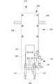
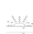
このように構成された液滴吐出ヘッド3は、そのヘッド本体50を、キャリッジ2に形成した装着開口18からキャリッジ2の裏面側に突出させ、装着開口18の縁部にあてがったヘッド保持部材4に上記のフランジ部58の部分でねじ止め固定される。また、ヘッド保持部材4は、キャリッジ2に接着により仮固定され、その後、機械的な固定手段を使って本固定される。  Thedroplet discharge head 3 configured as described above has the headmain body 50 projecting from the mountingopening 18 formed in thecarriage 2 to the back side of thecarriage 2 and being applied to the edge of the mountingopening 18. Are fixed by screws at theflange portion 58 described above. Further, thehead holding member 4 is temporarily fixed to thecarriage 2 by adhesion, and is then permanently fixed using a mechanical fixing means.

次に、図8および図9を参照して、ヘッド保持部材4について説明する。ヘッド保持部材4は、液滴吐出ヘッド3をキャリッジ2に安定に取り付けるための媒介金具であり、ステンレス等で構成された略長方形の平板状に形成されている。ヘッド保持部材4には、その中央に液滴吐出ヘッド3のヘッド本体50が挿通する方形の挿通開口71が形成されている。この場合、ヘッド保持部材4は、その長辺方向の両端部で装着開口(開口部位18a)18を跨ぐようにしてキャリッジ2の裏面側にセットされ、これに対し液滴吐出ヘッド3は、そのヘッド本体50を挿通開口71に挿通すようにしてキャリッジ2の表側にセットされる(図5参照)。  Next, thehead holding member 4 will be described with reference to FIGS. 8 and 9. Thehead holding member 4 is a medium fitting for stably attaching thedroplet discharge head 3 to thecarriage 2 and is formed in a substantially rectangular flat plate shape made of stainless steel or the like. Thehead holding member 4 is formed with asquare insertion opening 71 through which the headmain body 50 of thedroplet discharge head 3 is inserted. In this case, thehead holding member 4 is set on the back side of thecarriage 2 so as to straddle the mounting opening (openingportion 18a) 18 at both ends in the long side direction. Thehead body 50 is set on the front side of thecarriage 2 so as to be inserted through the insertion opening 71 (see FIG. 5).

ヘッド保持部材4の挿通開口71の周囲には、上記フランジ部58の2つのねじ孔59,59に対応する2つの貫通孔72,72および2本の小ねじ73,73と、2つの突出位置規制ピン74,74が配設されている。2つの貫通孔72,72は、それぞれ装着開口18側に突出する2つのボス部75,75に形成されている。この場合、各ボス部75は、ヘッド保持部材4に圧入した筒状のカラーで構成されている。この2つのボス部75,75と2つの突出位置規制ピン74,74とは、いずれも挿通開口71の中心に対し点対称位置に配設されており、これらボス部75,75と突出位置規制ピン74,74がヘッド本体50のフランジ部58に当接することにより、液滴吐出ヘッド3のキャリッジ2からの吐出寸法が規制されるようになっている。  Around theinsertion opening 71 of thehead holding member 4, there are two throughholes 72 and 72 and twosmall screws 73 and 73 corresponding to the twoscrew holes 59 and 59 of theflange portion 58, and two protruding positions. Restriction pins 74 are provided. The two throughholes 72 and 72 are formed in twoboss portions 75 and 75 that protrude to the mountingopening 18 side, respectively. In this case, eachboss 75 is formed of a cylindrical collar press-fitted into thehead holding member 4. The twoboss portions 75 and 75 and the two protruding position restricting pins 74 and 74 are both arranged at point-symmetrical positions with respect to the center of theinsertion opening 71. Thepins 74, 74 abut on theflange portion 58 of the headmain body 50, so that the discharge dimension of thedroplet discharge head 3 from thecarriage 2 is regulated.

また、挿通開口71の中心線上において、挿通開口71の外側には2つの係合孔76,76が形成されている。この2つの係合孔76,76は、後述する液滴吐出ヘッド3の組付治具Cが装着される部位であると同時に、組立装置Aにおける位置補正用の係合ピン343,343が係合される部位でもある。この場合、組付治具Cの装着や係合ピン343の係合が無理なく為されるように、2つの係合孔76,76は、一方が円形に、他方が上記中心線方向に長い長円形に形成されている。  In addition, on the center line of theinsertion opening 71, twoengagement holes 76 and 76 are formed outside theinsertion opening 71. The twoengagement holes 76 and 76 are portions where an assembly jig C of thedroplet discharge head 3 described later is mounted, and at the same time, engagement pins 343 and 343 for position correction in the assembly apparatus A are engaged. It is also a part to be combined. In this case, one of the twoengagement holes 76 and 76 is circular and the other is long in the direction of the center line so that the mounting jig C and theengagement pin 343 can be easily engaged. It is formed in an oval shape.

さらに、挿通開口71の中心線上において、ヘッド保持部材4の両端部には、それぞれ2つの接着剤注入孔77,77が、挿通開口71を挟んで対称位置に形成されている。各接着剤注入孔77はヘッド保持部材4の横断方向に延びる長孔となっており、この長孔のキャリッジ2側の端部は、面取りされている(図8参照)。各2つの接着剤注入孔77,77が形成されたヘッド保持部材4の両端部は、ヘッド保持部材4をキャリッジ2に接着するための接着部位78,78となっており、各接着剤注入孔77から注入された接着剤は、毛細管現象によりキャリッジ2と接着部位78,78との界面部分に広がって、塗着される。  Further, on the center line of theinsertion opening 71, two adhesive injection holes 77, 77 are formed at both ends of thehead holding member 4 at symmetrical positions with theinsertion opening 71 interposed therebetween. Eachadhesive injection hole 77 is a long hole extending in the transverse direction of thehead holding member 4, and the end of the long hole on thecarriage 2 side is chamfered (see FIG. 8). Both end portions of thehead holding member 4 in which the two adhesive injection holes 77 and 77 are formed are bondingportions 78 and 78 for bonding thehead holding member 4 to thecarriage 2. The adhesive injected from 77 is spread and applied to the interface between thecarriage 2 and thebonding parts 78 and 78 by capillary action.

この場合、一方の端部の外側(内側)に形成した接着剤注入孔77a(77b)と他方の端部の内側(外側)に形成した接着剤注入孔77a(77b)とは、それぞれ対となっている。詳細は後述するが、組立装置Aは2本の接着剤注入ノズル387,387を有しており、2本の接着剤注入ノズル387,387は、対となる一方の2つの接着剤注入孔77a,77aに同時に挿入されて接着剤を注入すると共に、上記中心線方向に移動した後、他方の2つの不接着剤注入孔77b,77bに同時に挿入されて接着剤を注入する。  In this case, theadhesive injection hole 77a (77b) formed on the outside (inside) of one end and theadhesive injection hole 77a (77b) formed on the inside (outside) of the other end are respectively paired. It has become. Although the details will be described later, the assembling apparatus A has twoadhesive injection nozzles 387 and 387, and the twoadhesive injection nozzles 387 and 387 form one pair of twoadhesive injection holes 77a. , 77a are simultaneously inserted to inject an adhesive, and after moving in the direction of the center line, the adhesive is injected by being simultaneously inserted into the other twonon-adhesive injection holes 77b, 77b.

なお、図中の符号79,79は、ヘッド保持部材4をキャリッジ2に仮装着するときに使用する(詳細は後述する)一対の締結孔であり、この一対の締結孔79,79は、それぞれ接着剤注入孔77,77の近傍であって、挿通開口71の中心に対し点対称位置に形成されている。また、キャリッジ2の開口部位18aには、この一対の締結孔79,79に対応する一対の仮締め用ねじ孔20,20が形成されている(図11参照)。  Reference numerals 79 and 79 in the drawing are a pair of fastening holes used when thehead holding member 4 is temporarily mounted on the carriage 2 (details will be described later). The pair of fastening holes 79 and 79 are respectively It is formed in the vicinity of the adhesive injection holes 77 and 77 at a point-symmetrical position with respect to the center of theinsertion opening 71. In addition, a pair of temporary fastening screw holes 20, 20 corresponding to the pair of fastening holes 79, 79 are formed in theopening portion 18a of the carriage 2 (see FIG. 11).

ところで、一対の基準ピン12,12を介して位置決めされるキャリッジ2に対し、各液滴吐出ヘッド3は、その出力端であるノズル列(吐出ノズル57)53を基準に、X軸、Y軸およびθ軸方向に位置決め(位置認識)される。より具体的には、2つのノズル列53,53は、製造段階で相互の位置精度が保証されているため、いずれか一方のノズル列53の最外端に位置する2つの吐出ノズル57a,57aを位置決め基準とし、これを認識するようにしている。また、液滴吐出ヘッド3のヘッド本体50における先端部の四辺(厳密には、ポンプ部48の数ミリ幅に亘る先端部の四辺)も、製造段階で相互の位置精度が保証されている。  By the way, with respect to thecarriage 2 that is positioned via the pair of reference pins 12, 12, eachdroplet discharge head 3 is based on the nozzle row (discharge nozzle 57) 53 that is the output end thereof, with reference to the X axis and Y axis. And positioning (position recognition) in the θ-axis direction. More specifically, since the positional accuracy of the twonozzle rows 53 and 53 is guaranteed in the manufacturing stage, the twodischarge nozzles 57a and 57a located at the outermost end of any one of thenozzle rows 53 are used. Is used as a positioning reference to recognize this. Further, the positional accuracy of the four sides of the tip of thedroplet discharge head 3 in the head main body 50 (strictly speaking, the four sides of the tip over the several millimeter width of the pump unit 48) is guaranteed at the manufacturing stage.

一方、液滴吐出ヘッド3は、ヘッド保持部材4を介してキャリッジ2に固定する形態である。そこで、本実施形態では、組付治具Cを用い、上記ヘッド本体50の先端部四辺を基準にして、液滴吐出ヘッド3をヘッド保持部材4に位置決めし、ねじ止め固定の後、上記2つの吐出ノズル57a,57aを基準にして、ヘッド保持部材4付き液滴吐出ヘッド3を位置決めし、仮固定するようにしている。すなわち、液滴吐出ヘッド3は、組付治具Cを用いた手作業により、いったんヘッド保持部材4に仮位置決めされ、続く組立装置Aでの画像認識(吐出ノズル57a,57aを認識)を経て、本位置決めされる。  On the other hand, thedroplet discharge head 3 is fixed to thecarriage 2 via thehead holding member 4. Therefore, in the present embodiment, the assembly jig C is used to position thedroplet discharge head 3 on thehead holding member 4 with reference to the four sides of the tip of thehead body 50, and after fixing with screws, the above 2 Thedroplet discharge head 3 with thehead holding member 4 is positioned and temporarily fixed with reference to the twodischarge nozzles 57a and 57a. That is, thedroplet discharge head 3 is temporarily positioned on thehead holding member 4 by manual operation using the assembling jig C, and then undergoes image recognition (recognizes thedischarge nozzles 57a and 57a) in the subsequent assembly apparatus A. The book is positioned.

実施形態の組立装置Aでは、位置認識のスピードアップを図るため、上記2つの吐出ノズル57a,57aを、固定的に設けた2つの認識カメラ353,353で同時に認識する、すなわち2つの認識カメラ353,353が同時に視野内に捕らえるようにしている。このため、組付治具Cを用いた液滴吐出ヘッド3の仮位置決めは、本位置決めの段階で、設定した位置データに基づいて、2つの認識カメラ353,353を上記の2つの吐出ノズル57a,57aに臨ませたときに、いずれも視野から外れることのないようにするものである。  In the assembly apparatus A of the embodiment, in order to speed up the position recognition, the twodischarge nozzles 57a and 57a are simultaneously recognized by the tworecognition cameras 353 and 353 that are fixedly provided, that is, the tworecognition cameras 353. , 353 are captured in the field of view at the same time. For this reason, the temporary positioning of thedroplet discharge head 3 using the assembling jig C is performed at the stage of the main positioning based on the set position data by using the tworecognition cameras 353 and 353 with the twodischarge nozzles 57a. , 57a so as not to deviate from the field of view.

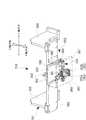
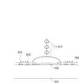
ここで、図9および図10を参照して、液滴吐出ヘッド3の組付治具Cについて説明すると共に、この組付治具Cを用いて液滴吐出ヘッド3をヘッド保持部材4に組み付ける組付方法について説明する。図10に示すように、組付治具Cは、液滴吐出ヘッド3のヘッド本体50を位置決めする治具本体81と、治具本体81をヘッド保持部材4に位置決め状態で装着する一対の装着ピン82,82とで構成されている。  Here, the assembly jig C of thedroplet discharge head 3 will be described with reference to FIGS. 9 and 10, and thedroplet ejection head 3 is assembled to thehead holding member 4 using the assembly jig C. The assembly method will be described. As shown in FIG. 10, the assembling jig C includes a jigmain body 81 for positioning the headmain body 50 of thedroplet discharge head 3 and a pair of mountings for mounting the jigmain body 81 on thehead holding member 4 in a positioned state. It consists ofpins 82 and 82.

治具本体81は、縦辺部84と、縦辺部84の両端から直角に延びる一対の横辺部85,85とで、略「C」字状に一体に形成されている。一方、一対の装着ピン82,82は、それぞれ横辺部85,85の裏面側から突出しており、この一対の装着ピン82,82をヘッド保持部材4の係合孔76,76に嵌合させることで、治具本体81がヘッド保持部材4に装着される。  Thejig body 81 is integrally formed in a substantially “C” shape with avertical side portion 84 and a pair ofhorizontal side portions 85, 85 extending perpendicularly from both ends of thevertical side portion 84. On the other hand, the pair of mountingpins 82, 82 protrude from the back side of the lateral sides 85, 85, respectively, and the pair of mountingpins 82, 82 are fitted into the engagement holes 76, 76 of thehead holding member 4. As a result, thejig body 81 is mounted on thehead holding member 4.

縦辺部84の内側から一方の横辺部85の内側に亘る部位には、略「L」字状の位置決め部86が形成され、この位置決め部86にヘッド本体50の一方の長辺および短辺を当接させることで、液滴吐出ヘッド3がヘッド保持部材4に位置決めされるようになっている。位置決め部86は、表側を他の部分と面一として薄肉に形成され、且つコーナー部分86aが半円状に窪入形成されている。また、治具本体81は、これをヘッド保持部材4に装着した状態で、その表面と液滴吐出ヘッド3のノズル形成面52とが、ほぼ面一(同レベル)とになるように、その厚みが設計されている。  A substantially “L” -shapedpositioning portion 86 is formed in a portion extending from the inside of thevertical side portion 84 to the inside of onehorizontal side portion 85, and one long side and a short side of the headmain body 50 are formed in thepositioning portion 86. Thedroplet discharge head 3 is positioned on thehead holding member 4 by contacting the sides. The positioningportion 86 is formed thin with the front side being flush with the other portions, and thecorner portion 86a is formed in a semicircular recess. In addition, thejig body 81 is mounted on thehead holding member 4 so that the surface thereof and thenozzle forming surface 52 of thedroplet discharge head 3 are substantially flush (same level). The thickness is designed.

これにより、ヘッド本体50はその突出方向の先端部が、組付治具Cの位置決め部86に当接して位置決めされるようになっている。すなわち、製造段階で、ノズル列53に対し位置精度が保証されたヘッド本体50における先端部の四辺のうち隣接する2つの辺を、組付治具Cの位置決め部86に突き当てることで、液滴吐出ヘッド3がヘッド保持部材4に位置決めされるようになっている。  Thus, the headmain body 50 is positioned such that the leading end in the protruding direction is in contact with thepositioning portion 86 of the assembling jig C. That is, at the manufacturing stage, two adjacent sides among the four sides of the tip end portion of the headmain body 50 whose positional accuracy is guaranteed with respect to thenozzle row 53 are abutted against the positioningportion 86 of the assembly jig C, whereby the liquid Thedroplet discharge head 3 is positioned on thehead holding member 4.

一方、一対の装着ピン82,82は、位置決め部86に突き当てたヘッド本体50の中心線に合致するように配設されている。より具体的には、位置決め部86の長辺部位86bは、一対の装着ピン82,82を結ぶ直線と平行に形成され、且つその離間寸法は、ヘッド本体50の長辺位置に合わせて管理されると共に、ヘッド本体50の短辺の1/2の寸法に形成されている。また、位置決め部86の短辺部位86cは、長辺部位86bに直角に形成され、且つ短辺部位86c側に位置する装着ピン82との離間寸法は、ヘッド本体50の短辺位置に合わせて管理されている。  On the other hand, the pair of mountingpins 82 and 82 are disposed so as to match the center line of the headmain body 50 that abuts against the positioningportion 86. More specifically, thelong side portion 86 b of thepositioning portion 86 is formed in parallel with a straight line connecting the pair of mountingpins 82, 82, and the separation dimension thereof is managed in accordance with the long side position of thehead body 50. In addition, thehead body 50 is formed to have a dimension that is ½ of the short side. Further, theshort side portion 86c of thepositioning portion 86 is formed at right angles to thelong side portion 86b, and the distance from the mountingpin 82 located on theshort side portion 86c side matches the short side position of thehead body 50. It is managed.

これにより、組付治具Cは、図9の状態から180°回転した状態で、ヘッド保持部材4に装着しても、特段の支障を生ずることなく、液滴吐出ヘッド3を位置決めすることができる。すなわち、実施形態の組付治具Cは、その平面形状が左右対称ではないが、いわゆる右勝手・左勝手のない構造となっている。  Thereby, the assembly jig C can position thedroplet discharge head 3 without causing any particular trouble even if it is mounted on thehead holding member 4 in a state rotated 180 ° from the state of FIG. it can. That is, the assembling jig C of the embodiment has a so-called right-handed / left-handed structure, although its planar shape is not symmetrical.

次に、図9、図11および図12を参照して、上記の組付治具Cを用いた、液滴吐出ヘッド3のヘッド保持部材4への組付方法について説明する。この組付作業は、組立装置Aの外工程として手作業で行われる。先ず、キャリッジ(厳密には本体プレート11)2の表側の周縁部に4本の支持脚88,88,88,88をねじ止めする。次いで、キャリッジ2を上下反転させ、キャリッジ2を支持脚88により浮いて状態にセットする。なお、図示では省略したが、この状態でキャリッジ2に、上記一対の支持部材13,13および一対の基準ピン12,12を取り付けておくことが、好ましい。  Next, a method for assembling thedroplet discharge head 3 to thehead holding member 4 using the assembly jig C will be described with reference to FIGS. This assembly work is performed manually as an external process of the assembly apparatus A. First, the foursupport legs 88, 88, 88, 88 are screwed to the front peripheral portion of the carriage (strictly, the main body plate 11) 2. Next, thecarriage 2 is turned upside down, and thecarriage 2 is set in a floating state by thesupport legs 88. Although not shown in the figure, it is preferable to attach the pair ofsupport members 13 and 13 and the pair of reference pins 12 and 12 to thecarriage 2 in this state.

次に、ヘッド本体50を上向きにした液滴吐出ヘッド3を、キャリッジ2の下側から装着開口18に挿入する。ここで、キャリッジ2の上側からヘッド保持部材4の挿通開口71をヘッド本体50に位置合わせし嵌め入れるようにして、ヘッド保持部材4をキャリッジ2上にセットする。ヘッド保持部材4をセットしたら、上側からヘッド保持部材4に組付治具Cを装着すると共に、ヘッド保持部材4の位置決め部86に、これに対峙するヘッド本体50の2辺を押し付ける。なお、組付治具Cを複数個用意しておいて、これを予めヘッド保持部材4に装着しておいてから、作業を開始してもよい。  Next, thedroplet discharge head 3 with thehead body 50 facing upward is inserted into the mountingopening 18 from the lower side of thecarriage 2. Here, thehead holding member 4 is set on thecarriage 2 so that theinsertion opening 71 of thehead holding member 4 is positioned and fitted into the headmain body 50 from above thecarriage 2. When thehead holding member 4 is set, the assembly jig C is mounted on thehead holding member 4 from above, and the two sides of the headmain body 50 facing the positioningmember 86 are pressed against the positioningportion 86 of thehead holding member 4. Note that a plurality of assembling jigs C may be prepared, and the work may be started after being mounted on thehead holding member 4 in advance.

続いて、上記の押付け状態を維持しつつ、上側から2本の小ねじ73,73を、ヘッド保持部材4を貫通して液滴吐出ヘッド3のフランジ部58にそれぞれ螺合し、液滴吐出ヘッド3をヘッド保持部材4に固定する。次に、2つの認識カメラ353,353の視野が、2つの吐出ノズル75a,75aから外れないようにする手段として、上記一対の締結孔79,79からキャリッジ2の仮締め用ねじ孔20,20に、それぞれ固定ねじ89,89を仮締め状態で螺合しておく(図9参照)。  Subsequently, while maintaining the above-mentioned pressing state, the twosmall screws 73, 73 from above are screwed into theflange portion 58 of thedroplet discharge head 3 through thehead holding member 4 to discharge the droplet. Thehead 3 is fixed to thehead holding member 4. Next, as means for preventing the fields of view of the tworecognition cameras 353 and 353 from being detached from the two discharge nozzles 75a and 75a, the screw holes 20 and 20 for temporary fastening of thecarriage 2 from the pair of fastening holes 79 and 79 are provided. The fixing screws 89 and 89 are screwed together in a temporarily tightened state (see FIG. 9).

これにより、固定ねじ89と締結孔79の寸法交差の範囲において、キャリッジ2に対する液滴吐出ヘッド3の位置合わせが可能となると共に、2つの認識カメラ353,353の視野が、2つの吐出ノズル75a,75aから外れることがなくなる。このようにして、液滴吐出ヘッド3のヘッド保持部材4への位置決めおよび固定を順に繰り返すことで、12個の液滴吐出ヘッド3が個々にヘッド保持部4に組み付けられる。最後に、ヘッド保持部材4から組付治具Cを引き抜くと共に4本の支持脚88を取り外して、作業を完了する。  As a result, thedroplet discharge head 3 can be positioned with respect to thecarriage 2 in the range of the dimension crossing between the fixingscrew 89 and thefastening hole 79, and the field of view of the tworecognition cameras 353 and 353 is two discharge nozzles 75a. , 75a. In this manner, by repeating the positioning and fixing of thedroplet discharge head 3 to thehead holding member 4 in order, twelve droplet discharge heads 3 are individually assembled to thehead holding unit 4. Finally, the assembly jig C is pulled out from thehead holding member 4 and the foursupport legs 88 are removed to complete the operation.

以上のようにして、キャリッジ2を挟んで、12個の液滴吐出ヘッド3が12個のヘッド保持部4に組み付けられるが、この状態では、12個の液滴吐出ヘッド3はキャリッジ2に固定されておらず、吊り下げられた状態となっている。すなわち、ヘッド保持部4付きの12個の液滴吐出ヘッド3は、キャリッジ2に対し、固定ねじ89と締結孔79の寸法交差範囲内で微小移動可能に、仮装着されている。なお、この固定ねじ89は捨てねじであり、組立装置Aにおいて、キャリッジ2にヘッド保持部4が接着された(仮固定)後に、取り外される。すなわち、実施形態では、ヘッド保持部4のキャリッジ2へのねじによる直接的な本固定は行わない(別部材による押圧固定とする)。  As described above, the 12 droplet discharge heads 3 are assembled to the 12head holding units 4 with thecarriage 2 interposed therebetween. In this state, the 12 droplet discharge heads 3 are fixed to thecarriage 2. It is not suspended and is in a suspended state. That is, the twelve droplet discharge heads 3 with thehead holding unit 4 are temporarily attached to thecarriage 2 so as to be minutely movable within the dimension crossing range of the fixingscrew 89 and thefastening hole 79. The fixingscrew 89 is a waste screw, and is removed after thehead holding portion 4 is bonded (temporarily fixed) to thecarriage 2 in the assembling apparatus A. That is, in the embodiment, the main fixing directly by screws to thecarriage 2 of thehead holding unit 4 is not performed (press fixing by another member).

そして、キャリッジ2に、ヘッド保持部材4付きの12個の液滴吐出ヘッド3が仮装着されたヘッドユニット1は、組立装置Aに導入され、上下反転姿勢のままこれにセットされる。なお、組立装置Aに導入されるヘッドユニット1は、上記の主構成部品に一対の支持部材13,13および基準ピン12,12を組み込んだものとなり、描画装置Bに導入されるヘッドユニット1は、これに更にハンドル14を始め、両アッセンブリ15,16等を組み込んだものとなる。  Then, thehead unit 1 in which the 12 droplet discharge heads 3 with thehead holding members 4 are temporarily mounted on thecarriage 2 is introduced into the assembling apparatus A and set in the upside down posture. Thehead unit 1 introduced into the assembling apparatus A is obtained by incorporating the pair ofsupport members 13 and 13 and the reference pins 12 and 12 into the main components, and thehead unit 1 introduced into the drawing apparatus B is In addition to this, thehandle 14 and bothassemblies 15, 16 and the like are incorporated.

ここで、描画装置Bについて簡単に説明すると共に、一対のハンドル14,14を利用してヘッドユニット1を描画装置Bに載せ込むヘッドユニット1のセット方法について説明する。また、液滴吐出ヘッド3のヘッド本体50の構造に関連して、描画装置Bのワイピング装置についても簡単に説明する。  Here, the drawing device B will be briefly described, and a method for setting thehead unit 1 for mounting thehead unit 1 on the drawing device B using a pair ofhandles 14 and 14 will be described. Further, the wiping device of the drawing device B will be briefly described in relation to the structure of the headmain body 50 of thedroplet discharge head 3.

図13は描画装置Bを模式的に表した概念図であり、同図に示すように、描画装置Bは、ヘッドユニット1を搭載しこれをY軸方向およびθ軸方向に移動させるヘッド移動部101と、ヘッド移動部101に対峙しカラーフィルタ等の基板102をX軸方向に移動させる基板移動部103と、ヘッドユニット1の液滴吐出ヘッド3を保全するメンテナンス部104とを備えている。ヘッド移動部101は、これに搭載したヘッドユニット1を、基板移動部103を挟んでユニット導入部105とメンテナンス部104との間で移動させる。  FIG. 13 is a conceptual diagram schematically showing the drawing apparatus B. As shown in the drawing, the drawing apparatus B is equipped with ahead unit 1 and moves thehead unit 1 in the Y-axis direction and the θ-axis direction. 101, asubstrate moving unit 103 that moves thesubstrate 102 such as a color filter in the X-axis direction, facing thehead moving unit 101, and amaintenance unit 104 that maintains thedroplet discharge head 3 of thehead unit 1. Thehead moving unit 101 moves thehead unit 1 mounted thereon between theunit introducing unit 105 and themaintenance unit 104 with thesubstrate moving unit 103 interposed therebetween.

ヘッドユニット1を導入セットする場合には、ヘッド移動部101がユニット導入部105側に移動し、その仮置き台106がユニット導入部105に臨んでいる。ヘッドユニット1は、この仮置き台106上に仮置きされ配管および配線を繋ぎこんだ後、ヘッド移動部101に送り込むようにしてセットされる。そして、ヘッドユニット1の初期位置決めを行う準備工程では、ヘッドユニット1のθ軸方向への微小移動(角度補正)が行われるが、フィルタ材料を吐出する製造工程では、基板102がX軸方向に且つヘッドユニット1がY軸方向に移動して、液滴吐出ヘッド3の主走査および副走査が行われる。  When thehead unit 1 is introduced and set, thehead moving unit 101 moves toward theunit introducing unit 105, and the temporary placement table 106 faces theunit introducing unit 105. Thehead unit 1 is temporarily placed on the temporary placement table 106 and connected to the piping and wiring, and then set to be fed into thehead moving unit 101. In the preparation process for initial positioning of thehead unit 1, thehead unit 1 is finely moved (angle correction) in the θ-axis direction. In the manufacturing process for discharging the filter material, thesubstrate 102 is moved in the X-axis direction. Further, thehead unit 1 moves in the Y-axis direction, and main scanning and sub-scanning of thedroplet discharge head 3 are performed.

ヘッド移動部101は、ヘッドユニット1を垂設するようにして支持するメインキャリッジ111と、メインキャリッジ111をθ軸方向に移動させるθテーブル112と、θテーブル112を介してヘッドユニット1をY軸方向に移動させるYテーブル113とを有している。また、基板移動部103は、基板102を吸着するようにしてセットする基板セットテーブル115と、基板セットテーブル115を介して基板をX軸方向に移動させるXテーブル116とを有している。  Thehead moving unit 101 includes amain carriage 111 that supports thehead unit 1 so as to be suspended, a θ table 112 that moves themain carriage 111 in the θ-axis direction, and thehead unit 1 that moves the Y-axis via the θ table 112. And a Y table 113 that is moved in the direction. In addition, thesubstrate moving unit 103 includes a substrate set table 115 that sets thesubstrate 102 so as to suck it, and an X table 116 that moves the substrate in the X-axis direction via the substrate set table 115.

この場合、Xテーブル116は、エアースライダとリニアモータとの組み合わせで駆動し、Yテーブル113は、ボールねじとサーボモータの組み合わせで駆動する(いずれも図示省略)。また、基板認識カメラ117はメインキャリッジ111に(図15参照)、ヘッド認識カメラ118は基板セットテーブル115に、それぞれ搭載されている。したがって、ヘッドユニット1のキャリッジ2に設けた一対の基準ピン12,12は、ヘッド認識カメラ118とこれをX軸方向に移動させるXテーブル116との協働により、画像認識される。  In this case, the X table 116 is driven by a combination of an air slider and a linear motor, and the Y table 113 is driven by a combination of a ball screw and a servo motor (both not shown). Theboard recognition camera 117 is mounted on the main carriage 111 (see FIG. 15), and thehead recognition camera 118 is mounted on the board set table 115. Therefore, the pair of reference pins 12 and 12 provided on thecarriage 2 of thehead unit 1 are recognized by the cooperation of thehead recognition camera 118 and the X table 116 that moves thehead recognition camera 118 in the X-axis direction.

ここで、図67を参照して、ヘッド認識カメラ118による一対の基準ピン12,12の認識動作について説明する。先ず、設計上のデータに基づいてXテーブル116およびYテーブル113が適宜駆動して、ヘッド認識カメラ118およびキャリッジ(ヘッドユニット1)を移動させ、一方の基準ピン12をヘッド認識カメラ118の視野内に取り込む。一方の基準ピン12をヘッド認識カメラ118で認識したら、次に、Xテーブル116を駆動し、ヘッド認識カメラ118をX軸方向(主走査方向)に移動させ、他方の基準ピン12をヘッド認識カメラ118の視野内に取り込んでこれを認識する。  Here, the recognition operation of the pair of reference pins 12 and 12 by thehead recognition camera 118 will be described with reference to FIG. First, the X table 116 and the Y table 113 are appropriately driven based on the design data to move thehead recognition camera 118 and the carriage (head unit 1), and onereference pin 12 is within the field of view of thehead recognition camera 118. Into. If onereference pin 12 is recognized by thehead recognition camera 118, then the X table 116 is driven, thehead recognition camera 118 is moved in the X-axis direction (main scanning direction), and theother reference pin 12 is moved to the head recognition camera. It is captured in the field of view of 118 and recognized.

そして、ヘッド認識カメラ118による一対の基準ピン12,12の認識結果に基づいて、Xテーブル116、Yテーブル113およびθテーブル112が適宜駆動して、キャリッジ(ヘッドユニット1)の位置補正が行われる。なお、位置補正後に、確認のため再度上記の認識動作が行われ、一連の認識動作が完了する。  Based on the recognition result of the pair of reference pins 12 and 12 by thehead recognition camera 118, the X table 116, the Y table 113, and the θ table 112 are appropriately driven to correct the position of the carriage (head unit 1). . In addition, after the position correction, the above recognition operation is performed again for confirmation, and a series of recognition operations is completed.

その後、実際の液滴吐出作業では、先ずXテーブル116が駆動し、基板102を主走査方向に往復移動させると共に複数の液滴吐出ヘッド3を駆動して、液滴吐出ヘッド3の選択的な液滴吐出が行われる。次に、Yテーブル113が駆動し、キャリッジ(ヘッドユニット1)2を1ピッチ分、副走査方向に移動させ、再度基板102の主走査方向への往復移動と液滴吐出ヘッド3の駆動が行われる。そしてこれを、数回繰り返すことで、基板102の端から端まで(全領域)液滴吐出が行われる。  Thereafter, in the actual droplet discharge operation, first, the X table 116 is driven to reciprocate thesubstrate 102 in the main scanning direction, and the plurality of droplet discharge heads 3 are driven. Droplet discharge is performed. Next, the Y table 113 is driven, the carriage (head unit 1) 2 is moved by one pitch in the sub-scanning direction, thesubstrate 102 is reciprocated in the main scanning direction, and thedroplet discharge head 3 is driven again. Is called. By repeating this several times, droplet discharge is performed from end to end (entire area) of thesubstrate 102.

このように、一対の基準ピン12,12の画像認識におけるヘッド認識カメラ118の移動を、Xテーブル116で行うようにしているため、ボールねじを用いるYテーブル113等と異なり、移動精度が認識精度に影響するのを防止することができる。また、Xテーブル116の移動方向であるX軸方向は、主走査方向に合致しており、構造上、液滴吐出の精度(着弾点の精度)を高めることができる。  In this way, since thehead recognition camera 118 is moved by the X table 116 in the image recognition of the pair of reference pins 12 and 12, the movement accuracy is different from the Y table 113 using a ball screw. Can be prevented. The X-axis direction, which is the moving direction of the X table 116, coincides with the main scanning direction, and the accuracy of droplet discharge (landing point accuracy) can be increased due to the structure.

なお、本実施形態では、ヘッドユニット(キャリッジ2)1に対し、その吐出対象物である基板102を主走査方向に移動させるようにしているが、キャリッジ(ヘッドユニット1)2を主走査方向に移動させる構成であってもよい。また、一対の基準ピン12,12をキャリッジ2の長辺方向の両端部に設けられる場合も考えられるが、かかる場合には、キャリッジ2のY軸方向への相対的移動により、一対の基準ピン12,12が認識されることとなる。  In the present embodiment, thesubstrate 102 that is the discharge target is moved in the main scanning direction with respect to the head unit (carriage 2) 1, but the carriage (head unit 1) 2 is moved in the main scanning direction. It may be configured to be moved. In addition, a case where the pair of reference pins 12 and 12 are provided at both ends in the long side direction of thecarriage 2 is also conceivable. In such a case, the pair of reference pins are moved by the relative movement of thecarriage 2 in the Y-axis direction. 12 and 12 are recognized.

図14および図15は、メインキャリッジ111の外観図である。メインキャリッジ111は、ヘッドユニット1が着座するベースプレート121と、ベースプレート121を垂設するように支持するアーチ部材122と、ベースプレート121の一方の端部に突出するように設けた仮置き台106である左右一対の仮置きアングル106a,106aと、ペースプレート121の他方の端部に設けたストッパプレート123とを備えている。なお、上記の基板認識カメラ117は、ストッパプレート121の外側に一対設けられている。  14 and 15 are external views of themain carriage 111. FIG. Themain carriage 111 is abase plate 121 on which thehead unit 1 is seated, anarch member 122 that supports thebase plate 121 so as to be suspended, and a temporary placement table 106 provided so as to protrude from one end of thebase plate 121. A pair of left and right temporary placement angles 106 a and 106 a and astopper plate 123 provided at the other end of thepace plate 121 are provided. A pair of thesubstrate recognition cameras 117 is provided outside thestopper plate 121.

ベースプレート121には、ヘッドユニット1の本体プレート11が遊嵌する方形開口124が形成され、またこの方形開口124を構成するベースプレート121の左右の各開口縁部125には、ヘッドユニット1の各支持部材13に形成した2つのボルト孔22,22およびピン孔23に合致する2つの貫通孔126,126と位置決めピン127とが設けられている。この場合、方形開口124の幅と本体プレート11の幅とがほぼ合致しており、側方からセットされるヘッドユニット1は、本体プレート11の左右が方形開口124の左右に案内されるようにして、挿入される。  Thebase plate 121 is formed with arectangular opening 124 into which themain body plate 11 of thehead unit 1 is loosely fitted, and the left and right opening edges 125 of thebase plate 121 constituting therectangular opening 124 are supported by thehead unit 1. Two throughholes 126, 126 matching the twobolt holes 22, 22 and thepin hole 23 formed in themember 13 and apositioning pin 127 are provided. In this case, the width of therectangular opening 124 and the width of themain body plate 11 are substantially matched, and thehead unit 1 set from the side is guided so that the left and right sides of themain body plate 11 are guided to the left and right of therectangular opening 124. Inserted.

各仮置きアングル106aは、十分な厚み(高さ)を有し、外側に「L」字状に屈曲した基部で、ベースプレート121の端部に載置するようにして固定されている。また、両仮置きアングル106a,106aの離間寸法は、ヘッドユニット1の両支持部材13,13の離間寸法に対応している。したがって、ヘッドユニット1は、その両支持部材13,13が両仮置きアングル106a,106aに着座することで仮置きされ、且つ両仮置きアングル106a,106aによりベースプレート121への送り込みが案内される。また、この状態で、各液滴吐出ヘッド3のヘッド本体50がベースプレート121から十分に浮いて、ベースプレート121との接触(干渉)が防止される。  Eachtemporary placement angle 106 a has a sufficient thickness (height) and is fixed so as to be placed on the end of thebase plate 121 with a base portion bent in an “L” shape on the outside. Further, the distance between the temporary placement angles 106 a and 106 a corresponds to the distance between the bothsupport members 13 and 13 of thehead unit 1. Therefore, thehead unit 1 is temporarily placed when both thesupport members 13 and 13 are seated on thetemporary placement angles 106a and 106a, and the feeding to thebase plate 121 is guided by thetemporary placement angles 106a and 106a. In this state, the headmain body 50 of eachdroplet discharge head 3 is sufficiently lifted from thebase plate 121, and contact (interference) with thebase plate 121 is prevented.

図16のイメージ図に示すように、ヘッドユニット1を、メインキャリッジ111のベースプレート121にセットする場合には、先ず両ハンドル14,14で手持ちして運び込んだヘッドユニット1を、両仮置きアングル106a,106a上に載置する(仮置き)。ここで、特に図示しないが、アーチ部材122上に配設した描画装置Bのフィルタ材料供給系のチューブをヘッドユニット1の配管接続アッセンブリ15に配管接続すると共に、制御系のケーブルを配線接続アッセンブリ16に配線接続する(同図(a))。  As shown in the image diagram of FIG. 16, when thehead unit 1 is set on thebase plate 121 of themain carriage 111, thehead unit 1 that is first carried by both thehandles 14, 14 is moved to thetemporary placement angle 106 a, It is placed on 106a (temporary placement). Here, although not particularly illustrated, the tube of the filter material supply system of the drawing apparatus B disposed on thearch member 122 is connected to thepiping connection assembly 15 of thehead unit 1 and the control system cable is connected to thewiring connection assembly 16. Are connected by wiring ((a) in the figure).

接続作業が完了したら、再度ハンドル14,14を把持し、両仮置きアングル106a,106aをガイドにしてヘッドユニット1を先方に押し入れ、更にその先端部を下げるように傾ける(同図(b))。ヘッドユニット1を傾けてゆくと、本体プレート11の先端部が方形開口124に挿入され、且つ両支持部材13,13の先端が方形開口124の両開口縁部125,125に着地する。両支持部材13,13が開口縁部125,125に着地したら、両仮置きアングル106a,106aから両支持部材13,13を浮かせるようにし、こんどは両支持部材13,13の先端を中心に、ヘッドユニット1を、開口縁部125上をスライドさせながら更に奥に向かって押し込んでゆく。  When the connection work is completed, thehandles 14 and 14 are gripped again, thehead unit 1 is pushed forward with thetemporary placement angles 106a and 106a as guides, and the tip unit is further tilted so as to be lowered ((b) in the figure). . When thehead unit 1 is tilted, the distal end portion of themain body plate 11 is inserted into therectangular opening 124, and the distal ends of bothsupport members 13, 13 land on both openingedge portions 125, 125 of therectangular opening 124. When bothsupport members 13, 13 land on the opening edges 125, 125, thesupport members 13, 13 are allowed to float from thetemporary placement angles 106a, 106a. Thehead unit 1 is pushed further back while sliding on theopening edge 125.

そして、ヘッドユニット1の先端がストッパプレート123に突き当たったら、ヘッドユニット1の後部をゆっくり下げて、両支持部材13,13のピン孔23に両開口縁部125,125の位置決めピン127を嵌合させるようにして、ヘッドユニット1をベースプレート121上に着座させる。ここで、ベースプレート121の下側からベースプレート121を貫通して、4本の固定ねじ128を両支持部材13,13に螺合し、作業を完了する(同図(c))。  When the front end of thehead unit 1 hits thestopper plate 123, the rear part of thehead unit 1 is slowly lowered, and the positioning pins 127 of both openingedge portions 125, 125 are fitted into the pin holes 23 of bothsupport members 13, 13. Thus, thehead unit 1 is seated on thebase plate 121. Here, thebase plate 121 is penetrated from the lower side of thebase plate 121, and the four fixingscrews 128 are screwed to thesupport members 13 and 13, thereby completing the operation (FIG. 3C).

このように、ユニット導入部105において、ヘッドユニット1を仮置きし、この状態で必要な配管・配線接続を行うようにしているため、これら接続作業が行い易く、且つ接続作業後のヘッドユニット1を狭いスペースに適切にセットすることができる。また、ヘッドユニット1を、仮置きアングル106aから一段低いベースプレート121に、スライドさせながらセットするようにしているため、ヘッドユニット1をメインキャリッジ111にソフトランディングさせるようにセットすることができ、重いヘッドユニット1を、衝撃なく円滑にセットすることができる。  Thus, since thehead unit 1 is temporarily placed in theunit introduction part 105 and necessary piping and wiring connections are made in this state, these connection operations are easy to perform and thehead unit 1 after the connection operation is performed. Can be set appropriately in a narrow space. Further, since thehead unit 1 is set while being slid on thebase plate 121 that is one step lower than thetemporary placement angle 106a, thehead unit 1 can be set so as to be soft-landed on themain carriage 111. Theunit 1 can be set smoothly without impact.

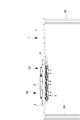
一方、描画装置Bのメンテナンス部104には、キャッピング装置やクリーニング装置に併設するようにワイピング装置が設けられている。図17に示すように、ワイピング装置108は、ワイピングシート131を備えるワイピングユニット132と、ワイピングユニット132をヘッドユニット1に向かって進退させる移動機構133とを有している。Yテーブル113によりメンテナンス部104に導入されたヘッドユニット1に対し、移動機構133がワイピングユニット132をX軸方向(主走査方向)に進退させるようにして拭取り動作させる。  On the other hand, themaintenance unit 104 of the drawing apparatus B is provided with a wiping device so as to be attached to the capping device and the cleaning device. As illustrated in FIG. 17, thewiping device 108 includes awiping unit 132 including awiping sheet 131 and a movingmechanism 133 that moves thewiping unit 132 forward and backward toward thehead unit 1. The movingmechanism 133 causes thewiping unit 132 to advance and retract in the X-axis direction (main scanning direction) with respect to thehead unit 1 introduced into themaintenance unit 104 by the Y table 113.

ワイピングユニット133は、ワイピングシート131をロール状に巻回した繰出しリール135と、繰出しリール135から繰り出したワイピングシート131を巻き取る巻取りリール136と、繰出しリール135および巻取りリール136間においてワイピングシート131を掛け渡したワイピングローラ137とを備えている。また、繰出しリール135とワイピングローラ137との間には、回転速度検出軸を兼ねるガイドローラ138が配設され、且つワイピングローラ137の近傍には、洗浄液供給ヘッド139が配設されている。  Thewiping unit 133 includes afeeding reel 135 in which thewiping sheet 131 is wound in a roll shape, a take-upreel 136 for taking up thewiping sheet 131 fed out from thefeed reel 135, and a wiping sheet between thefeed reel 135 and the take-upreel 136. And a wipingroller 137 over which 131 is wound. Aguide roller 138 that also serves as a rotational speed detection shaft is disposed between the feedingreel 135 and the wipingroller 137, and a cleaningliquid supply head 139 is disposed in the vicinity of the wipingroller 137.

繰出しリール135は、これに設けたトルクリミッタにより制動回転し、巻取りリール136は、これに設けたモータにより駆動回転する。繰出しリール135から繰り出されたワイピングシート131は、ガイドローラ138をくぐって経路変更され、洗浄液供給ヘッド139から洗浄液の供給を受けた後、ワイピングローラ137を周回し、巻取りリール136に巻き取られる。  Thesupply reel 135 is braked and rotated by a torque limiter provided thereon, and the take-upreel 136 is driven and rotated by a motor provided thereon. Thewiping sheet 131 fed out from the feedingreel 135 is routed through theguide roller 138 and supplied with the cleaning liquid from the cleaningliquid supply head 139, and then circulates around the wipingroller 137 and is wound around the take-upreel 136. .

ワイピングローラ137は、自由回転ローラであり、弾力性或いは柔軟性を有するゴムローラ等で構成されている。ワイピング時におけるワイピングローラ137は、ワイピングシート131を各液滴吐出ヘッド3のヘッド本体50に下側から押し付けるように作用する。また、ワイピング時には、ワイピングローラ137は巻取りリール136の回転を受けて走行するワイピングシート131により回転し、且つ移動機構133により、ワイピングユニット133全体としてX軸方向に移動する。これにより、ワイピングシート131が、ヘッドニットの下面、すなわち12個の液滴吐出ヘッド3のヘッド本体50に順に摺接してゆく。言い換えれば、ヘッド本体50の相対的な移動方向に対し、ワイピングシート131が逆方向に走行し、各ヘッド本体50のノズル形成面52が拭き取られることになる。  The wipingroller 137 is a free rotating roller, and is composed of a rubber roller having elasticity or flexibility. The wipingroller 137 during wiping acts to press the wipingsheet 131 against thehead body 50 of eachdroplet discharge head 3 from below. Further, at the time of wiping, the wipingroller 137 is rotated by the wipingsheet 131 that travels by receiving the rotation of the take-upreel 136, and is moved in the X-axis direction as a whole by the movingmechanism 133. As a result, the wipingsheet 131 comes into sliding contact with the lower surface of the head knit, that is, the headmain body 50 of the twelve droplet discharge heads 3 in order. In other words, the wipingsheet 131 travels in the opposite direction with respect to the relative movement direction of the headmain body 50, and thenozzle forming surface 52 of each headmain body 50 is wiped off.

ヘッド本体50に摺接してゆくワイピングシート131には、ワイピングローラ137に達する直前に、洗浄液供給ヘッド139から洗浄液、すなわちフィルタ材料の溶剤等が供給される。これにより、各ヘッド本体50のノズル形成面52に付着したフィルタ材料は、ワイピングローラ137を介して洗浄液を含浸したワイピングシート131により、きれいに拭き取られる。また、上述したように、ヘッド本体50の下端部はこれにモールドした樹脂62により、面取りされているため、このワイピングの際にヘッド本体50がワイピングシート131につかえることがない。  Immediately before reaching the wipingroller 137, the cleaning liquid, that is, the solvent of the filter material, is supplied from the cleaningliquid supply head 139 to thewiping sheet 131 that is in sliding contact with thehead body 50. As a result, the filter material adhering to thenozzle forming surface 52 of eachhead body 50 is wiped cleanly by the wipingsheet 131 impregnated with the cleaning liquid via the wipingroller 137. Further, as described above, since the lower end portion of the headmain body 50 is chamfered by theresin 62 molded thereon, the headmain body 50 is not held by the wipingsheet 131 during the wiping.

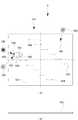
次に、図18および図19を参照して、アライメントマスクDについて説明する。実施形態の組立装置Aでは、ヘッドユニット1の組立個数に係わらず、常に一定レベルの組立精度を有するヘッドユニット1を供給する必要がある。そこで、キャリッジ2および12個の液滴吐出ヘッド3の基準位置をマークしたアライメントマスクDを用意している。すなわち、アライメントマスクDを部品位置の原型(原版)とし、複製としてのヘッドユニット1を、この組立装置Aで組み立てるようにしている。これにより、ヘッドユニット1に対する各組立装置Aが持つ癖や経時変化等の精度的影響を排除するようにしている。  Next, the alignment mask D will be described with reference to FIGS. In the assembly apparatus A of the embodiment, it is necessary to always supply thehead unit 1 having a certain level of assembly accuracy regardless of the number ofhead units 1 assembled. Therefore, an alignment mask D in which the reference positions of thecarriage 2 and the twelve droplet discharge heads 3 are marked is prepared. That is, the alignment mask D is used as a prototype (original) at the part position, and thehead unit 1 as a duplicate is assembled by the assembling apparatus A. As a result, precision effects such as wrinkles and changes with time of each assembly apparatus A with respect to thehead unit 1 are eliminated.

アライメントマスクDは、キャリッジ2の基準位置および各液滴吐出ヘッド3の基準位置をマスクパターン形成したマスタプレート161と、マスタプレート161を下側から保持するプレートホルダ162とで構成されている。上述したように、各液滴吐出ヘッド3は、主走査方向に対し所定の角度(角度40°〜60°)傾けて配設されている。そこで、マスタプレート161およびプレートホルダ162は、この傾き角度に合わせて形成されている。  The alignment mask D includes amaster plate 161 in which a reference position of thecarriage 2 and a reference position of eachdroplet discharge head 3 are formed as a mask pattern, and aplate holder 162 that holds themaster plate 161 from the lower side. As described above, eachdroplet discharge head 3 is disposed at a predetermined angle (angle 40 ° to 60 °) with respect to the main scanning direction. Therefore, themaster plate 161 and theplate holder 162 are formed according to this inclination angle.

より具体的には、マスタプレート161は、傾けて搭載される液滴吐出ヘッド3のヘッド本体50に対応し、その長辺に平行な2辺と短辺に平行な2辺とで方形に形成され、無駄な部分が生じないようにしている。また、マスタプレート161は、原型として狂いが生じないように厚手の透明な石英ガラスで構成されている。  More specifically, themaster plate 161 corresponds to thehead body 50 of thedroplet discharge head 3 mounted at an inclination, and is formed in a square shape with two sides parallel to the long side and two sides parallel to the short side. This prevents unnecessary parts from being generated. Further, themaster plate 161 is made of thick transparent quartz glass so as not to be distorted as a prototype.

マスタプレート161の表面には、各液滴吐出ヘッド3の基準位置を表す各5つのヘッド基準マーク164,164,164,164,164を1組として、これが両側に6組ずつ計12組形成されている。また、この12組のヘッド基準マーク164の外側には、キャリッジ2の基準位置を表す一対のキャリッジ基準マーク165,165が形成されている。さらに、端部に位置するヘッド基準マーク164の近傍には、認識カメラ353の画素分解能を調整するための被写体画像166が形成されている。  On the surface of themaster plate 161, five sets of head reference marks 164, 164, 164, 164, and 164 representing the reference position of eachdroplet discharge head 3 are formed as one set, and a total of 12 sets of 6 sets are formed on both sides. ing. A pair of carriage reference marks 165 and 165 representing the reference position of thecarriage 2 are formed outside the 12 sets of head reference marks 164. Further, asubject image 166 for adjusting the pixel resolution of therecognition camera 353 is formed in the vicinity of thehead reference mark 164 located at the end.

各5つのヘッド基準マーク164は、液滴吐出ヘッド3におけるノズル形成面52の中心位置と、2列のノズル列53,53のそれぞれ最外端部に位置する計4つの吐出ノズル57,57,57,57の位置を表示している。図18(a)に示すように、各ヘッド基準マーク164は、円形ラインの内部に中抜きの十字を描くと共に、十字を除く円形内に斜線を描いて形成されている。したがって、これを認識カメラ353で画像認識(撮像)すると、暗色の円形部分の内部に、明色の十字部分が認識される。  Each of the five head reference marks 164 includes a total of fourdischarge nozzles 57, 57, 57 located at the center position of thenozzle forming surface 52 in thedroplet discharge head 3 and the outermost ends of the twonozzle rows 53, 53. Thepositions 57 and 57 are displayed. As shown in FIG. 18A, eachhead reference mark 164 is formed by drawing a hollow cross inside a circular line and drawing a diagonal line inside the circle excluding the cross. Therefore, when the image is recognized (captured) by therecognition camera 353, a bright cross is recognized inside the dark circular portion.

上記と同様に、各キャリッジ基準マーク165も、円形ラインの内部に中抜きの十字を描くと共に、十字を除く円形内に斜線を描いて形成されている。また、被写体画像166は、格子状に精度良く描いた縦横の多数のラインで形成されている。なお、ノズル形成面52の中心位置を表すヘッド基準マーク164は、4つの吐出ノズル57の位置を表す4つのヘッド基準マーク164から演算可能であるため、省略してもよい。なお、アライメントマスクDに形成されたパターンは、Cr等の金属に代表される不透明膜を一面形成し、その膜を半導体技術を用いてパターニングする等して形成される。  Similarly to the above, eachcarriage reference mark 165 is also formed by drawing a hollow cross inside the circular line and by drawing a diagonal line inside the circle excluding the cross. Further, thesubject image 166 is formed by a large number of vertical and horizontal lines drawn accurately in a grid pattern. Thehead reference mark 164 representing the center position of thenozzle forming surface 52 can be omitted because it can be calculated from the four head reference marks 164 representing the positions of the fourdischarge nozzles 57. The pattern formed on the alignment mask D is formed by forming one surface of an opaque film typified by a metal such as Cr and patterning the film using semiconductor technology.

プレートホルダ162は、図19および図20に示すように、マスタプレート161より一回り大きく形成した略方形のマスタ支持プレート168と、マスタ支持プレート168の裏面四隅に取り付けた樹脂製の4つの脚ブロック169,169,169,169と、マスタ支持プレート168の表面に設けられたマスタプレート161を縦横不動に位置決めする複数のウレタンストッパ170と、マスタプレート161をマスタ支持プレート168上に浮いた状態で支持する複数の支持ピン171と、支持ピン171に対応して設けられマスタプレート168を上側から押さえる複数の押さえブロック172とを備えている。  As shown in FIGS. 19 and 20, theplate holder 162 includes a substantially squaremaster support plate 168 formed slightly larger than themaster plate 161 and four resin-made leg blocks attached to four corners on the back surface of themaster support plate 168. 169, 169, 169, 169, a plurality ofurethane stoppers 170 for positioning themaster plate 161 provided on the surface of themaster support plate 168 vertically and horizontally, and themaster plate 161 supported in a floating state on themaster support plate 168 And a plurality of pressingblocks 172 provided corresponding to the supportingpins 171 and pressing themaster plate 168 from above.

複数のウレタンストッパ170は、マスタプレート161の四辺に各2個ずつ突き当てられている。また、複数の支持ピン171は、マスタプレート161の隅部に各2個ずつ配置され、且つマスタ支持プレート168に対し高さ調節可能に取り付けられている。すなわち、各支持ピン171は、アジャストボルトの構造を有しており、マスタプレート161の表面、すなわちマーク形成面161aのレベルを調整できるようになっている。複数の押さえブロック172は、それぞれ支持ピン171に対応しており、支持ピン171との間にマスタプレート161を挟み込むようにして、これを押さえている。  The plurality ofurethane stoppers 170 are each abutted against the four sides of themaster plate 161. The plurality of support pins 171 are arranged at two corners of themaster plate 161, and are attached to themaster support plate 168 so that the height can be adjusted. That is, eachsupport pin 171 has an adjustment bolt structure, and the level of the surface of themaster plate 161, that is, themark forming surface 161a can be adjusted. Each of the plurality of pressingblocks 172 corresponds to thesupport pin 171, and holds themaster plate 161 so as to be sandwiched between the support pins 171.

このように構成されたアライメントマスクDは、後述する組立装置Aのセットテーブル231に固定される。このため、マスタ支持プレート168の左右の各縁部には、2つの固定孔173,173と、2つの固定孔173,173間に配設したピン孔174とが形成されている。そして、アライメントマスクDとヘッドユニット1とは、組立装置Aのセットテーブル231に交換セットされる。  The alignment mask D configured in this way is fixed to a set table 231 of the assembly apparatus A described later. For this reason, two fixingholes 173 and 173 and pinholes 174 disposed between the two fixingholes 173 and 173 are formed on the left and right edges of themaster support plate 168. The alignment mask D and thehead unit 1 are exchanged and set on the set table 231 of the assembly apparatus A.

次に、液滴吐出ヘッド3の組立装置Aおよび組立方法について説明する。組立装置Aは、キャリッジ2に12個の液滴吐出ヘッド3を仮装着した上記のヘッドユニット1を組立対象物とし、ヘッドユニット1のキャリッジ2に各液滴吐出ヘッド3を精度良く位置決めして接着(仮固定)するものである。なお、この組立装置Aで、液滴吐出ヘッド3を仮固定したヘッドユニット1は、洗浄工程および上記のハンドル14等の部品組込み工程を経て、描画装置Bにセットされる。  Next, the assembling apparatus A and assembling method of thedroplet discharge head 3 will be described. The assembling apparatus A uses the above-describedhead unit 1 in which twelve droplet discharge heads 3 are temporarily mounted on thecarriage 2 as an object to be assembled, and accurately positions eachdroplet discharge head 3 on thecarriage 2 of thehead unit 1. Bonding (temporary fixing). In this assembling apparatus A, thehead unit 1 to which thedroplet discharge head 3 is temporarily fixed is set in the drawing apparatus B through a cleaning process and a part incorporation process such as thehandle 14 described above.

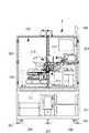
図21ないし図25の外観図に示すように、組立装置Aは、架台201上に透明な安全カバー202を有し、架台201にエアー供給機器203等を組み込むと共に、安全カバー202内に機台204に載置するようにして主構成装置205を収容して、構成されている。架台201には、4個のキャスタ206と6個のアジャストボルト付き支持脚207とが設けられている。安全カバー202の正面には、ヘッドユニット1を導入するための開閉扉208が設けられ、またその上面には、警告灯209が立設されている。  As shown in the external views of FIGS. 21 to 25, the assembling apparatus A has atransparent safety cover 202 on thegantry 201, anair supply device 203 and the like are incorporated in thegantry 201, and a machine base is installed in thesafety cover 202. Themain component device 205 is accommodated and configured so as to be placed on 204. Thegantry 201 is provided with fourcasters 206 and sixsupport legs 207 with adjusting bolts. An opening /closing door 208 for introducing thehead unit 1 is provided on the front surface of thesafety cover 202, and awarning lamp 209 is erected on the upper surface thereof.

主構成装置205は、ヘッドユニット1を搭載しこれを水平面内においてX・Y・θ方向に移動させるユニット移動装置211と、キャリッジ2に仮装着されている各液滴吐出ヘッド3の位置補正を行うヘッド補正装置212と、キャリッジ2に各液滴吐出ヘッド3を接着する仮固定装置213と、液滴吐出ヘッド3の位置補正に先立ってキャリッジ2および各液滴吐出ヘッド3を位置認識する認識装置214と、これらユニット移動装置211、ヘッド補正装置212、仮固定装置213および認識装置214を統括制御する制御装置(図50参照)215とを備えている。  Themain component device 205 mounts thehead unit 1 and corrects the position of theunit moving device 211 that moves thehead unit 1 in the X, Y, and θ directions in the horizontal plane, and eachdroplet discharge head 3 temporarily mounted on thecarriage 2. Ahead correction device 212 to perform, atemporary fixing device 213 for adhering eachdroplet discharge head 3 to thecarriage 2, and recognition for recognizing the position of thecarriage 2 and eachdroplet discharge head 3 prior to position correction of thedroplet discharge head 3. Theapparatus 214 includes aunit moving device 211, ahead correction device 212, atemporary fixing device 213, and a control device (see FIG. 50) 215 that performs overall control of therecognition device 214.

この組立装置Aでは、予めユニット移動装置211に上記のアライメントマスクDを導入し、認識装置214によりアライメントマスクDの各基準マーク164,165を画像認識して、キャリッジ2および各液滴吐出ヘッド3の基準位置データを記憶し、この基準位置データ(マスタデータ)に基づいてキャリッジ2および各液滴吐出ヘッド3の位置補正が行われる。なお、アライメントマスクDは、新規のヘッドユニット1の導入組立時は元より、同一のヘッドユニット1であっても、その組立個数や稼動時間に基づいて、定期的に導入される。もちろん、その際に基準位置データはリセットされる。  In the assembling apparatus A, the alignment mask D is introduced into theunit moving device 211 in advance, and the reference marks 164 and 165 of the alignment mask D are image-recognized by the recognizingdevice 214, and thecarriage 2 and the droplet discharge heads 3 are recognized. The reference position data is stored, and the position correction of thecarriage 2 and eachdroplet discharge head 3 is performed based on the reference position data (master data). Note that the alignment mask D is periodically introduced based on the number of assembly and the operating time of thesame head unit 1 from the beginning when thenew head unit 1 is introduced and assembled. Of course, the reference position data is reset at that time.

一方、ヘッドユニット1は、各液滴吐出ヘッド3のヘッド本体50を上向きにしてユニット移動装置211の上面にセットされ、ヘッドユニット1の組立ては、先ず認識装置214によるキャリッジ2の位置認識からスタートする。キャリッジ2が位置認識されると、この認識データと基準位置データとが比較され、その比較結果に基づいて、ユニット移動装置211によりキャリッジ2の位置補正が行われる。次に、認識装置214により液滴吐出ヘッド3が位置認識され、この認識結果(比較結果)に基づいてヘッド補正装置212により、液滴吐出ヘッド3の位置補正が行われる。  On the other hand, thehead unit 1 is set on the upper surface of theunit moving device 211 with the headmain body 50 of eachdroplet discharge head 3 facing upward, and the assembly of thehead unit 1 starts from the recognition of the position of thecarriage 2 by therecognition device 214 first. To do. When the position of thecarriage 2 is recognized, the recognition data is compared with the reference position data, and the position of thecarriage 2 is corrected by theunit moving device 211 based on the comparison result. Next, the position of thedroplet discharge head 3 is recognized by therecognition device 214, and the position of thedroplet discharge head 3 is corrected by thehead correction device 212 based on the recognition result (comparison result).

続いて、この位置補正状態を維持しつつ、仮固定装置213により、ヘッド保持部材4を介して液滴吐出ヘッド3がキャリッジ2に接着される。またその際、接着剤が硬化するまで、ヘッド補正装置212は、液滴吐出ヘッド(ヘッド保持部材4)3を動かないように押さえている。そして、この液滴吐出ヘッド3の位置認識から接着までの工程を、液滴吐出ヘッド3の個数分繰り返えすようにし、全液滴吐出ヘッド3の仮固定が完了する。  Subsequently, thedroplet discharge head 3 is bonded to thecarriage 2 via thehead holding member 4 by thetemporary fixing device 213 while maintaining this position correction state. At that time, thehead correction device 212 holds the droplet discharge head (head holding member 4) 3 so as not to move until the adhesive is cured. Then, the steps from the position recognition of thedroplet discharge head 3 to the bonding are repeated for the number of droplet discharge heads 3, and the temporary fixing of all the droplet discharge heads 3 is completed.

図21および図26に示すように、ユニット移動装置211は、3個所のアジャストボルト217により水平に支持した板状の機台204に、広い占有面積をもって載置されている。ユニット移動装置211は、ヘッドユニット1を反転状態でセットするセットテーブル231と、セットテーブル231を下側から支持するθテーブル232と、θテーブル232を下側から支持するX・Yテーブル233とを、備えている。ヘッドユニット1は、セットテーブル231と共に搭載した液滴吐出ヘッド3の傾きに合わせ、傾けてセットされている。このため、液滴吐出ヘッド3の主走査方向に相当する方向がX軸方向となり、副走査方向がY軸方向となる。  As shown in FIGS. 21 and 26, theunit moving device 211 is placed on a plate-like machine base 204 supported horizontally by threeadjustment bolts 217 with a large occupation area. Theunit moving device 211 includes a set table 231 for setting thehead unit 1 in an inverted state, a θ table 232 for supporting the set table 231 from the lower side, and an XY table 233 for supporting the θ table 232 from the lower side. Have. Thehead unit 1 is set to be inclined in accordance with the inclination of thedroplet discharge head 3 mounted together with the set table 231. For this reason, the direction corresponding to the main scanning direction of thedroplet discharge head 3 is the X-axis direction, and the sub-scanning direction is the Y-axis direction.

図27に示すように、セットテーブル231は、複数の円形抜き孔236を形成した方形のベースプレート235と、ベースプレート235の両側に固定した一対の帯状ブロック237,237とを有している。各帯状ブロック237の上面には、位置決めピン238が立設される共に2つのねじ孔239,239が形成されている。すなわち、ヘッドユニット1はセットテーブル231に対し、左右の2個所で位置決めされ、計4個所でねじ止め固定されるようになっている。また、ベースプレート235の中央部分には、セットテーブル231をθテーブル232に固定するための4つの貫通孔240等が形成されている。  As shown in FIG. 27, the set table 231 includes arectangular base plate 235 in which a plurality ofcircular holes 236 are formed, and a pair of belt-like blocks 237 and 237 fixed on both sides of thebase plate 235. On the upper surface of each belt-like block 237, twoscrew holes 239 and 239 are formed so that thepositioning pin 238 is erected. That is, thehead unit 1 is positioned at two positions on the left and right with respect to the set table 231 and is fixed with screws at a total of four positions. Further, four throughholes 240 and the like for fixing the set table 231 to the θ table 232 are formed in the central portion of thebase plate 235.

このように、ヘッドユニット1は、セットテーブル231を介してθテーブル232に固定され、同様にアライメントマスクDも、セットテーブル231を介してθテーブル232に固定されるようになっている。この場合、ヘッドユニット1とアライメントマスクDとは、θテーブル232に固定したヘッドユニット1の各液滴吐出ヘッド3のノズル形成面52と、θテーブル232に固定したアライメントマスクDのマーク形成面(マスタプレートの表面)161aとが、同一水平面内に位置するように設計されている。  Thus, thehead unit 1 is fixed to the θ table 232 via the set table 231, and the alignment mask D is similarly fixed to the θ table 232 via the set table 231. In this case, thehead unit 1 and the alignment mask D include thenozzle formation surface 52 of eachdroplet discharge head 3 of thehead unit 1 fixed to the θ table 232 and the mark formation surface of the alignment mask D fixed to the θ table 232 ( Themaster plate surface 161a is designed to be located in the same horizontal plane.

同様に、ヘッドユニット1の重量と、プレートホルダ162を含むアライメントマスクDの重量とが、略同一重量となるように設計されている。これにより、アライメントマスクDの位置認識動作とヘッドユニット1の位置認識動作とを、全く同一条件で行えるようにしている。なお、セットテーブル231は、ヘッドユニット1に対し専用部品となっており、ヘッドユニット1が変更されるとこれに合わせてセットテーブル231も変更される。  Similarly, the weight of thehead unit 1 and the weight of the alignment mask D including theplate holder 162 are designed to be substantially the same weight. Thereby, the position recognition operation of the alignment mask D and the position recognition operation of thehead unit 1 can be performed under exactly the same conditions. The set table 231 is a dedicated component for thehead unit 1, and when thehead unit 1 is changed, the set table 231 is also changed accordingly.

次に、図28、図29および図30を参照して、θテーブル232について説明する。θテーブル232は、セットテーブル231を介してヘッドユニット1を微小回転(微小回動)させる回転作動部242と、回転作動部242を駆動する進退駆動部243とで構成されている。回転作動部242は、セットテーブル231が固定されるテーブル本体245と、テーブル本体245から進退駆動部243側に延びる連結アーム246と、テープル本体245を回転自在に支持するローラリング247と、ローラリング247を支持する支持台248とを有している。この場合、セットテーブル231は、テーブル本体245に設けた2個所の位置決めピン250,250と、4個所のねじ孔251を介して、テーブル本体245の上面に位置決め状態でねじ止めされている。  Next, the θ table 232 will be described with reference to FIGS. 28, 29, and 30. The θ table 232 includes arotation operation unit 242 that slightly rotates (micro rotation) thehead unit 1 via the set table 231 and an advance /retreat drive unit 243 that drives therotation operation unit 242. Therotation operation unit 242 includes a tablemain body 245 to which the set table 231 is fixed, a connectingarm 246 extending from the tablemain body 245 toward the advance /retreat drive unit 243, aroller ring 247 that rotatably supports the tablemain body 245, and a roller ring. And asupport base 248 for supporting 247. In this case, the set table 231 is screwed to the upper surface of the tablemain body 245 in a positioned state via twopositioning pins 250 and 250 provided on the tablemain body 245 and four screw holes 251.

進退駆動部243は、動力源を構成するθテーブルモータ(サーボモータ)253と、θテーブルモータ253の主軸254にカップリング255を介して連結されボールねじ256と、ボールねじ256が螺合する雌ねじブロック257と、雌ねじブロック257をボールねじ256の軸方向(X軸方向に)にスライド自在に支持する主スライダ258とを有しており、また上記の連結アーム246の先端部が連結されアーム受け260と、ベアリング261を介してアーム受け260を回動自在に軸支する鉛直軸部材262と、雌ねじブロック257に対し鉛直軸部材262をY軸方向にスライド自在に支持する副スライダ263とを有している。  The advancing / retreatingdrive unit 243 includes a θ table motor (servo motor) 253 constituting a power source, aball screw 256 coupled to themain shaft 254 of theθ table motor 253 via acoupling 255, and a female screw into which theball screw 256 is screwed. And amain slider 258 that slidably supports thefemale screw block 257 in the axial direction of the ball screw 256 (in the X-axis direction). The distal end of the connectingarm 246 is connected to the arm receiver. 260, avertical shaft member 262 that pivotally supports thearm receiver 260 via abearing 261, and a sub-slider 263 that supports thevertical shaft member 262 slidably in the Y-axis direction with respect to thefemale screw block 257. is doing.

θテーブルモータ253は正逆回転可能に構成され、θテーブルモータ253が正逆回転すると、ボールねじ256により、雌ねじブロック257が主スライダ258に案内されてX軸方向に進退する。雌ねじブロック257が進退すると、これに支持されている副スライダ263おび鉛直軸部材262もX軸方向に進退する。さらに、鉛直軸部材262が進退すると、これに軸着されているアーム受け260を介して、連結アーム246およびテーブル本体245がテーブル本体245の軸心を中心に回動する。すなわち、テーブル本体245が水平面内において、正逆微小回転する(θ方向に正逆移動)。  Theθ table motor 253 is configured to be able to rotate in the forward and reverse directions. When theθ table motor 253 rotates in the forward and reverse directions, thefemale screw block 257 is guided by themain slider 258 by theball screw 256 and moves forward and backward in the X-axis direction. When the female screw block 257 advances and retracts, theauxiliary slider 263 and thevertical shaft member 262 supported by thefemale screw block 257 also advance and retract in the X-axis direction. Further, when thevertical shaft member 262 advances and retreats, the connectingarm 246 and the tablemain body 245 rotate around the axis of the tablemain body 245 through thearm receiver 260 attached to thevertical shaft member 262. That is, the tablemain body 245 rotates slightly forward and backward in the horizontal plane (forward and backward movement in the θ direction).

また、この回動に伴って、テーブル本体245と鉛直軸部材262との中心間距離が変化するが、この距離の変化は、副スライダ263を介して鉛直軸部材262がY軸方向に適宜、微小移動することにより吸収される。なお、雌ねじブロック257から突出する遮光板265と、雌ねじブロック257の進退に伴って遮光板265が臨む3個のフォトインタラプタ266により、雌ねじブロック257の移動端位置、すなわちテーブル本体245の回動範囲(角度)が規制されるようになっている(オーバーランの防止)。  In addition, the distance between the centers of the tablemain body 245 and thevertical shaft member 262 changes with this rotation. This change in the distance is caused by thevertical shaft member 262 being appropriately moved in the Y-axis direction via thesub slider 263. It is absorbed by a minute movement. The moving end position of thefemale screw block 257, that is, the rotation range of the tablemain body 245 is determined by thelight shielding plate 265 protruding from thefemale screw block 257 and the threephoto interrupters 266 that thelight shielding plate 265 faces as the female screw block 257 advances and retreats. (Angle) is regulated (prevention of overrun).

進退駆動部243は、主スライダ258の下側に設けた支持プレート267に支持されており、この支持プレート267が回転作動部242の支持台248に固定されている。そして、この支持台248がX・Yテーブル233に載置されている。  The advancing / retreatingdrive unit 243 is supported by asupport plate 267 provided below themain slider 258, and thissupport plate 267 is fixed to thesupport base 248 of therotation operation unit 242. Thesupport base 248 is placed on the XY table 233.

次に、図26、図31および図32を参照して、X・Yテーブル233について説明する。X・Yテーブル233は、θテーブル232を下側から支持する支持ブロック270と、支持ブロック270をX軸方向にスライド自在に支持するX軸テーブル271と、X軸テーブル271をY軸方向にスライド自在に支持するY軸テーブル272とを有している。支持ブロック270には、4箇所にねじ孔274を有しており、この4箇所にねじ孔274を介して支持ブロック270にθテーブル232が固定されている。  Next, the XY table 233 will be described with reference to FIGS. 26, 31 and 32. FIG. The X / Y table 233 includes asupport block 270 that supports the θ table 232 from below, an X-axis table 271 that supports thesupport block 270 slidably in the X-axis direction, and a slide of the X-axis table 271 in the Y-axis direction. And a Y-axis table 272 that is freely supported. Thesupport block 270 hasscrew holes 274 at four locations, and the θ table 232 is fixed to thesupport block 270 via the screw holes 274 at the four locations.

X軸テーブル271は、X軸エアースライダ276と、X軸リニアモータ277と、X軸エアースライダ276に併設したX軸リニアスケール278とで構成されている。同様に、Y軸テーブル272は、Y軸エアースライダ279と、Y軸リニアモータ280と、Y軸エアースライダ279に併設したY軸リニアスケール281とで構成されている。なお、図中の符号、282,283は、それぞれX軸ケーブルベアおよびY軸ケーブルベアである。また、符号284,284は、両リニアモータ277,280のアンプである。  The X-axis table 271 includes anX-axis air slider 276, an X-axislinear motor 277, and an X-axislinear scale 278 provided along with theX-axis air slider 276. Similarly, the Y-axis table 272 includes a Y-axis air slider 279, a Y-axislinear motor 280, and a Y-axislinear scale 281 provided alongside the Y-axis air slider 279.Reference numerals 282 and 283 in the figure denote an X-axis cable bear and a Y-axis cable bear, respectively.Reference numerals 284 and 284 denote amplifiers for bothlinear motors 277 and 280.

X軸リニアモータ277およびY軸リニアモータ280は、適宜制御駆動され、θテーブル232をX軸方向およびY軸方向に移動させる。すなわち、セットテーブル231にセットされたヘッドユニット(或いはアライメントマスクD)1は、水平面内において、θテーブル231によりθ軸方向に移動すると共に、X・Yテーブル233によりX軸方向およびY軸方向に移動する。  The X-axislinear motor 277 and the Y-axislinear motor 280 are appropriately controlled and moved to move the θ table 232 in the X-axis direction and the Y-axis direction. That is, the head unit (or alignment mask D) 1 set on the set table 231 moves in the θ-axis direction by the θ table 231 in the horizontal plane, and in the X-axis direction and the Y-axis direction by the XY table 233. Moving.

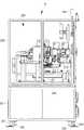
次に、ヘッド補正装置212について説明する。ヘッド補正装置212は、認識装置214による液滴吐出ヘッド3の位置認識に基づき、ヘッド保持部材4を介して液滴吐出ヘッド3をX軸、Y軸およびθ軸方向に微小移動させて、液滴吐出ヘッド3の位置決め(位置補正)を行うものである。また同時に、ヘッド補正装置212は仮固定装置213と協働し、接着剤が凝固するまでヘッド保持部材4をキャリッジ2に押し付けるよう機能する。  Next, thehead correction device 212 will be described. Thehead correction device 212 finely moves thedroplet discharge head 3 in the X-axis, Y-axis, and θ-axis directions via thehead holding member 4 on the basis of the position recognition of thedroplet discharge head 3 by therecognition device 214, Thedroplet ejection head 3 is positioned (position correction). At the same time, thehead correction device 212 functions in cooperation with thetemporary fixing device 213 to press thehead holding member 4 against thecarriage 2 until the adhesive is solidified.

図23および図33に示すように、ヘッド補正装置212は、上記の機台204の奥側に取り付けた補正装置用スタンド301と、これに載置された補正用X・Yテーブル302と、補正用X・Yテーブル302に支持された補正用θテーブル303と、補正用θテーブル303に支持されたアームユニット304とで構成されている。この場合、補正用θテーブル303は、ユニット移動装置211のθテーブル232と全く同一の構造を有しているため、ここでは説明を省略する。なお、θテーブル232ではその進退駆動部243が左側に位置するように配設されているが、この補正用θテーブル303では右側に位置するように配設されている(図23参照)。  As shown in FIGS. 23 and 33, thehead correction device 212 includes a correction device stand 301 attached to the back side of themachine base 204, a correction X / Y table 302 mounted thereon, and a correction device. The correction θ table 303 is supported by the X / Y table 302 and thearm unit 304 is supported by the correction θ table 303. In this case, the correction θ table 303 has exactly the same structure as the θ table 232 of theunit moving device 211, and thus description thereof is omitted here. In the θ table 232, the advancing / retreatingdrive unit 243 is disposed on the left side, but in the correction θ table 303, it is disposed on the right side (see FIG. 23).

補正装置用スタンド301は、図33に示すように、補正用X・Yテーブル302が載置されるベースプレート307と、ベースプレート307を支持する3組の脚ユニット308,308,308とを有している。3組の脚ユニット308は、左部、右部および中央後部の3個所に配設されており、それぞれ一対の支柱309,309と、一対の支柱309,309の上下に固定した上板310および下板311とで構成されている。  As shown in FIG. 33, thecorrection device stand 301 includes abase plate 307 on which the correction X / Y table 302 is placed, and three sets ofleg units 308, 308, and 308 that support thebase plate 307. Yes. The three sets ofleg units 308 are arranged at three locations, the left part, the right part, and the central rear part, respectively, and a pair ofsupport columns 309 and 309, and anupper plate 310 fixed above and below the pair ofsupport columns 309 and 309, and It consists of alower plate 311.

この場合、補正装置用スタンド301の下側空間には、ユニット移動装置211により移動するヘッドユニット1が臨み、補正装置用スタンド301から張り出したアームユニット304がこのヘッドユニット1に上側から臨む(ヘッド保持部材4に係合)ようになっている。そして、ヘッドユニット1の移動およびキャリッジ2の位置補正は、ユニット移動装置211により行われ、各液滴ヘッド3の位置補正は、このヘッド補正装置212により行われる。したがって、任意の1の液滴吐出ヘッド3が仮固定された後、ユニット移動装置211がヘッドユニット1を移動させて、次の液滴吐出ヘッド3をヘッド補正装置212に臨ませる。  In this case, thehead unit 1 moved by theunit moving device 211 faces the lower space of thecorrection device stand 301, and thearm unit 304 protruding from the correction device stand 301 faces thehead unit 1 from above (head). Engaging with the holding member 4). The movement of thehead unit 1 and the position correction of thecarriage 2 are performed by theunit moving device 211, and the position correction of eachdroplet head 3 is performed by thehead correction device 212. Therefore, after any onedroplet discharge head 3 is temporarily fixed, theunit moving device 211 moves thehead unit 1 so that the nextdroplet discharge head 3 faces thehead correction device 212.

図33ないし図36に示すように、補正用X・Yテーブル302は、補正装置用スタンド301の中央に載置されており、補正用θテーブル302を支持する支持ブロック314と、支持ブロック314をX軸方向にスライド自在に支持する補正用X軸テーブル315と、補正用X軸テーブル315をY軸方向にスライド自在に支持する補正用Y軸テーブル316とを有している。支持ブロック314には、4箇所にねじ孔318を有しており、この4箇所にねじ孔318を介して支持ブロック314に補正用θテーブル303が固定されている。  As shown in FIGS. 33 to 36, the correction X / Y table 302 is placed in the center of thecorrection device stand 301, and includes asupport block 314 that supports the correction θ table 302, and asupport block 314. A correction X-axis table 315 is slidably supported in the X-axis direction, and a correction Y-axis table 316 is slidably supported in the Y-axis direction. Thesupport block 314 hasscrew holes 318 at four locations, and the correction θ table 303 is fixed to thesupport block 314 via the screw holes 318 at the four locations.

補正用X軸テーブル315は、X軸エアースライダ320と、X軸リニアモータ321と、X軸エアースライダ320に併設したX軸リニアスケール322とで構成されている。同様に、補正用Y軸テーブル316は、Y軸エアースライダ323と、Y軸リニアモータ324と、Y軸エアースライダ323に併設したY軸リニアスケール325とで構成されている。なお、図中の符号、326,327は、それぞれX軸ケーブルベアおよびY軸ケーブルベアであり、また、符号328,328は、両リニアモータ321,324のアンプである。  The correction X-axis table 315 includes anX-axis air slider 320, an X-axislinear motor 321, and an X-axislinear scale 322 provided along with theX-axis air slider 320. Similarly, the correction Y-axis table 316 includes a Y-axis air slider 323, a Y-axislinear motor 324, and a Y-axislinear scale 325 provided along with the Y-axis air slider 323. In the figure,reference numerals 326 and 327 are an X-axis cable bear and a Y-axis cable bear, respectively, andreference numerals 328 and 328 are amplifiers of bothlinear motors 321 and 324, respectively.

図37、図38および図39に示すように、アームユニット304は、ヘッド保持部材4の一対の係合孔76,76に係合する一対の係合アーム331,331と、一対の係合アーム331,331を支持するブラケット332と、ブラケット332を昇降させるアーム昇降機構333と、アーム昇降機構333を支持する支持台334とで構成されている。支持台334は、補正用θテーブル303に固定される固定板336と、固定板336から前方に延びる一対のL字アーム337,337と、一対のL字アーム337,337の前端に固定した鉛直板338とで構成され、前方に向かって逆「L」字状に延在している。  As shown in FIGS. 37, 38, and 39, thearm unit 304 includes a pair ofengagement arms 331 and 331 that engage with the pair of engagement holes 76 and 76 of thehead holding member 4, and a pair of engagement arms. It includes abracket 332 that supports 331 and 331, anarm lifting mechanism 333 that lifts and lowers thebracket 332, and asupport base 334 that supports thearm lifting mechanism 333. Thesupport base 334 includes a fixedplate 336 fixed to the correction θ table 303, a pair of L-shapedarms 337 and 337 extending forward from the fixedplate 336, and a vertical fixed to the front ends of the pair of L-shapedarms 337 and 337. It is comprised with theboard 338, and is extended in reverse "L" shape toward the front.

アーム昇降機構333は、ブラケット332を昇降自在に支持する昇降スライダ340と、鉛直板338の下部に固定され昇降スライダ340を昇降させるエアーシリンダ341とで構成されている。エアーシリンダ341は、上記のエアー供給機器203に接続されており、エアーバルブ等の切り替えにより昇降スライダ340を案内にしてブラケット332を昇降させる。ブラケット332は、「L」字状に形成され、先端が二股に形成されている。そして、この二股部分に、それぞれ係合アーム331,331が下向きに取り付けられている。  Thearm elevating mechanism 333 includes an elevatingslider 340 that supports thebracket 332 so as to be movable up and down, and anair cylinder 341 that is fixed to the lower portion of thevertical plate 338 and moves up and down the elevatingslider 340. Theair cylinder 341 is connected to theair supply device 203 described above, and moves thebracket 332 up and down with thelift slider 340 as a guide by switching the air valve or the like. Thebracket 332 is formed in an “L” shape, and has a bifurcated tip. Then, theengagement arms 331 and 331 are attached downward to the forked portion, respectively.

各係合アーム331は、図40に示すように、ヘッド保持部材4の係合孔76に挿入される係合ピン343と、係合ピン343を上下動自在に保持するピンホルダ344と、ピンホルダ344に内蔵され係合ピン343を下方に付勢するコイルばね345とを有している。ピンホルダ344の上端部は、ブラケット332に下側から嵌合するようにして固定されている。係合ピン343の先端部は、テーパー形状に形成されており、このテーパー部347は、ヘッド保持部材4の係合孔76に対し基端側が太径に先端側が細径に形成されている。これにより、係合ピン343は係合孔76にがたつきなく、係合するようになっている。  As shown in FIG. 40, eachengagement arm 331 includes anengagement pin 343 inserted into theengagement hole 76 of thehead holding member 4, apin holder 344 that holds theengagement pin 343 up and down, and apin holder 344. And acoil spring 345 that urges theengaging pin 343 downward. The upper end portion of thepin holder 344 is fixed so as to be fitted to thebracket 332 from below. The distal end portion of theengaging pin 343 is formed in a tapered shape, and the taperedportion 347 is formed such that the proximal end side has a large diameter and the distal end side has a small diameter with respect to the engaginghole 76 of thehead holding member 4. As a result, theengagement pin 343 is engaged with theengagement hole 76 without rattling.

初期状態において、両係合アーム331,331はエアーシリンダ341により上昇端位置に移動しており、ユニット移動装置211によりヘッドユニット1を移動させた後、エアーシリンダ341により両係合アーム331,331を下降させると、その一対の係合ピン343,343が、所望のヘッド保持部材4の係合孔76,76に係合する。また、エアーシリンダ341は、上記の制御装置215によりタイマー制御されており、仮固定装置213により塗布された接着剤が凝固するまで、位置補正後のヘッド保持部材4をそのままキャリッジ2に押圧している。  In the initial state, both theengagement arms 331 and 331 are moved to the rising end position by theair cylinder 341, and after moving thehead unit 1 by theunit moving device 211, the bothengagement arms 331 and 331 are moved by theair cylinder 341. Is lowered, the pair of engagement pins 343 and 343 engage with the engagement holes 76 and 76 of the desiredhead holding member 4. Theair cylinder 341 is timer-controlled by thecontrol device 215, and thehead holding member 4 after position correction is pressed against thecarriage 2 as it is until the adhesive applied by thetemporary fixing device 213 is solidified. Yes.

すなわち、両係合アーム331,331を下降させたエアーシリンダ341は、ヘッド保持部材4の位置補正および接着剤の塗布(詳細後述する)が行われた後、接着剤の凝固時間(所定の接着強度に達する時間)が経過した時に両係合アーム331,331を元の位置に上昇させる。なお、本実施形態では、係合ピン343をコイルばね345で付勢するようにしているが、コイルばね345を省略し、係合ピン343とピンホルダ344とを一体化した単純な構造にしてもよい。  That is, theair cylinder 341 in which both theengagement arms 331 and 331 are lowered is subjected to the position correction of thehead holding member 4 and the application of the adhesive (details will be described later), and then the adhesive coagulation time (predetermined adhesion) When the time to reach the strength elapses, both theengagement arms 331 and 331 are raised to their original positions. In this embodiment, the engagingpin 343 is urged by thecoil spring 345. However, thecoil spring 345 is omitted, and theengaging pin 343 and thepin holder 344 are integrated into a simple structure. Good.

以上の構成では、アームユニット304の両係合アーム331,331が下降して、ヘッド保持部材4に係合すると、補正用θテーブル303および補正用X・Yテーブル302が駆動して、ヘッド保持部材4を介して液滴吐出ヘッド3を位置決めする。そして、接着剤が凝固するまで、この位置決め状態が維持される。すなわち、アームユニット304の両係合アーム331,331が、位置きめ状態でヘッド保持部材4をキャリッジ2に向かって押さえており、このヘッド保持部材4に仮固定装置(接着)213が臨むことになる。  In the above configuration, when both the engagingarms 331 and 331 of thearm unit 304 are lowered and engaged with thehead holding member 4, the correction θ table 303 and the correction XY table 302 are driven to hold the head. Thedroplet discharge head 3 is positioned via themember 4. This positioning state is maintained until the adhesive is solidified. That is, both theengagement arms 331 and 331 of thearm unit 304 press thehead holding member 4 toward thecarriage 2 in a positioned state, and the temporary fixing device (adhesion) 213 faces thehead holding member 4. Become.

次に、認識装置214について説明する。図24および図41に示すように、認識装置214は、補正用X・Yテーブル302の前部を跨ぐように補正装置用スタンド301上に固定したカメラスタンド351と、カメラスタンド351の前面に固定したカメラ位置調節ユニット352と、カメラ位置調節ユニット352に取り付けた一対の認識カメラ(CCDカメラ)353,353とで構成されている。この場合、一対の認識カメラ353,353は、認識対象となるヘッドユニット(アライメントマスクD)1に対し、固定的に設けられている。  Next, therecognition device 214 will be described. As shown in FIG. 24 and FIG. 41, therecognition device 214 is fixed on the correction device stand 301 so as to straddle the front part of the correction X / Y table 302, and fixed on the front surface of thecamera stand 351. And a pair of recognition cameras (CCD cameras) 353 and 353 attached to the cameraposition adjustment unit 352. In this case, the pair ofrecognition cameras 353 and 353 are fixedly provided with respect to the head unit (alignment mask D) 1 to be recognized.

カメラスタンド351は、逆「L」字状に前方に延びる左右一対の脚片部材355,355と、一対の脚片部材355,355間に渡した横長の前面プレート356とを有している。カメラ位置調節ユニット352を介して前面プレート356に固定された一対の認識カメラ353,353は、ヘッド補正装置212の一対の係合アーム331,331より幾分高い位置に、且つ幾分前方に張り出した位置に配設され(図25参照)、係合アーム331との干渉が防止されるようになっている。  Thecamera stand 351 has a pair of left and rightleg piece members 355 and 355 extending forward in an inverted “L” shape, and a horizontally longfront plate 356 extending between the pair ofleg piece members 355 and 355. The pair ofrecognition cameras 353 and 353 fixed to thefront plate 356 via the cameraposition adjustment unit 352 protrudes somewhat higher than the pair ofengagement arms 331 and 331 of thehead correction device 212 and somewhat forward. (See FIG. 25) so that interference with theengagement arm 331 is prevented.

図41ないし図44に示すように、カメラ位置調節ユニット352は、前面プレート356に添設したZ軸調整プレート358と、Z軸調整プレート358の下端部に取り付けたマイクロステージ359と、左側の認識カメラ353aを保持する左カメラホルダ360と、右側の認識カメラ353bを保持する右カメラホルダ361とを有している。Z軸調整プレート358は、前面プレート356との間に鉛直方向に延びる一対のガイドレール362,362を有すると共に、前面プレート356の上端に突き当てたアジャストボルト363を有している。このアジャストボルト363の正逆回転により、Z軸調整プレート358を介して、両認識カメラ353,353の上下方向の位置が調節できるようになっている。  As shown in FIGS. 41 to 44, the cameraposition adjustment unit 352 includes a Z-axis adjustment plate 358 attached to thefront plate 356, amicrostage 359 attached to the lower end of the Z-axis adjustment plate 358, and a left side recognition. It has aleft camera holder 360 that holds thecamera 353a and aright camera holder 361 that holds theright recognition camera 353b. The Z-axis adjustment plate 358 has a pair ofguide rails 362 and 362 extending in the vertical direction between the Z-axis adjustment plate 356 and anadjustment bolt 363 that abuts against the upper end of thefront plate 356. By the forward and reverse rotation of the adjustingbolt 363, the vertical positions of therecognition cameras 353 and 353 can be adjusted via the Z-axis adjusting plate 358.

マイクロステージ359は、右カメラホルダ361を介して右側の認識カメラ353bを支持するX軸ステージ365と、X軸ステージ365を支持すると共にZ軸調整プレート358の下端部に固定したY軸ステージ366とで構成されている。X軸ステージ365は、右側の認識カメラ353bをX軸方向に微小移動可能に構成され、右側の認識カメラ353bにおける前後方向の位置を調節可能に構成されている。同様に、Y軸ステージ366は、右側の認識カメラ353bにおける左右方向の位置を調節可能に構成されている。  Themicrostage 359 includes anX-axis stage 365 that supports theright recognition camera 353b via theright camera holder 361, and a Y-axis stage 366 that supports theX-axis stage 365 and is fixed to the lower end of the Z-axis adjustment plate 358. It consists of TheX-axis stage 365 is configured such that theright recognition camera 353b can be moved minutely in the X-axis direction, and the position in the front-rear direction of theright recognition camera 353b can be adjusted. Similarly, the Y-axis stage 366 is configured to be able to adjust the position in the left-right direction of theright recognition camera 353b.

一方、左カメラホルダ360は、Z軸調整プレート358の下端部に固定されている。このため、左カメラホルダ360を介して固定的に設けた左側の認識カメラ353aに対し、右側の認識カメラ353bをマイクロステージ359で位置調節するようになっている。上述したように、左右の認識カメラ353a,353bにより、2つの吐出ヘッド57a,57aを同時に位置認識するため、特に新規の液滴吐出ヘッド3を扱うときには、予めマイクロステージ359により、左右の認識カメラ353a,353bの離間距離、すなわち視野間距離を調節するようにしている。なお、図中の符号367は、カメラ位置調節ユニット352および両認識カメラ353,353を一体に覆うカメラカバーである。  On the other hand, theleft camera holder 360 is fixed to the lower end of the Z-axis adjustment plate 358. Therefore, the position of theright recognition camera 353b is adjusted by themicrostage 359 with respect to theleft recognition camera 353a fixedly provided via theleft camera holder 360. As described above, since the positions of the twoejection heads 57a and 57a are simultaneously recognized by the left andright recognition cameras 353a and 353b, the left and right recognition cameras are preliminarily used by themicrostage 359 in advance, particularly when the newdroplet ejection head 3 is handled. The separation distance between 353a and 353b, that is, the distance between the visual fields is adjusted.Reference numeral 367 in the figure denotes a camera cover that integrally covers the cameraposition adjustment unit 352 and therecognition cameras 353 and 353.

このように構成された認識装置214では、一方の認識カメラ353とユニット移動機構211のX軸テーブル271との協働により、キャリッジ2の2つの基準マーク(基準ピン12,12)26,26が位置認識される。すなわち、一方の認識カメラ353により一方の基準ピン12の画像認識が行われ、続いてキャリッジ2がX軸方向に移動して他方の基準ピン12の画像認識が行われる。そして、この認識結果に基づいて、ユニット移動装置211によりキャリッジ(ヘッドユニット1)2の位置補正が行われ、さらに確認のため再度の位置認識が行われる。  In therecognition device 214 configured as described above, the two reference marks (reference pins 12 and 12) 26 and 26 of thecarriage 2 are formed by the cooperation of onerecognition camera 353 and the X-axis table 271 of theunit moving mechanism 211. The position is recognized. That is, image recognition of onereference pin 12 is performed by onerecognition camera 353, and then thecarriage 2 moves in the X-axis direction to perform image recognition of theother reference pin 12. Based on the recognition result, the position of the carriage (head unit 1) 2 is corrected by theunit moving device 211, and the position is recognized again for confirmation.

また、一対の認識カメラ353,353により、各液滴吐出ヘッド3の基準となる2つの吐出ノズル57a,57aが、同時に位置認識される。すなわち、該当する液滴吐出ヘッド3が一対の認識カメラ353,353の直下に移動して、2つの吐出ヘッド57a,57aが同時に画像認識される。また、この状態で、ヘッド保持部材4にヘッド補正装置212が臨んで、液滴吐出ヘッド3の位置補正が行われる、且つ仮固定装置213による接着が行われる。なお、アライメントマスクDにおける各マーク164,165の認識も、上記と同様に為される。  The pair ofrecognition cameras 353 and 353 simultaneously recognizes the positions of the twodischarge nozzles 57a and 57a serving as the reference of eachdroplet discharge head 3. That is, the correspondingdroplet discharge head 3 moves immediately below the pair ofrecognition cameras 353 and 353, and the twodischarge heads 57a and 57a are simultaneously image-recognized. In this state, thehead correction device 212 faces thehead holding member 4, the position of thedroplet discharge head 3 is corrected, and thetemporary fixing device 213 is bonded. Themarks 164 and 165 on the alignment mask D are recognized in the same manner as described above.

次に、仮固定装置213について説明する。図22および図45に示すように、上記の機台204の右部には、補正装置用スタンド301を跨ぐようにして前後方向に延びる共有スタンド219が設けられており、仮固定装置213は、この共有スタンド219の前部に配設されている。仮固定装置213は、4本のステー371で共有スタンド219に支持した方形支持プレート372と、方形支持プレート372の下面に固定したエアーテーブル373と、エアーテーブル373の先端部に固定した接着剤塗布装置374と、ホーム位置に移動した接着剤塗布装置374に下側から臨む接着剤トレイ375とを備えている。接着剤トレイ375は、共有スタンド219に固定されており、接着剤塗布装置374から垂れた接着剤を受けるようになっている。  Next, thetemporary fixing device 213 will be described. As shown in FIGS. 22 and 45, acommon stand 219 extending in the front-rear direction so as to straddle thecorrection device stand 301 is provided on the right side of themachine base 204, and thetemporary fixing device 213 is It is disposed at the front of the sharedstand 219. Thetemporary fixing device 213 includes asquare support plate 372 supported on acommon stand 219 by fourstays 371, an air table 373 fixed to the lower surface of thesquare support plate 372, and an adhesive application fixed to the tip of the air table 373. Adevice 374 and anadhesive tray 375 facing theadhesive applicator 374 moved to the home position from below are provided. Theadhesive tray 375 is fixed to thecommon stand 219, and receives the adhesive hanging from theadhesive application device 374.

図45ないし図49に示すように、エアーテーブル373は、方形支持プレート372に取り付けたY軸エアーテーブル377と、Y軸エアーテーブル377の先端部に取り付けたサブY軸エアーテーブル378と、サブY軸エアーテーブル378の先端部に取り付けたX軸エアーテーブル379と、X軸エアーテーブル379の先端部に取り付けたZ軸エアーテーブル380とで構成されている。そして、これらY軸エアーテーブル377、サブY軸エアーテーブル378、X軸エアーテーブル379およびZ軸エアーテーブル380は、いずれも上記のエアー供給機器203に接続されたエアーシリンダ377a,378a,379a,380aと、スライダ377b,378b,379b,380bとで構成されている。  45 to 49, the air table 373 includes a Y-axis air table 377 attached to arectangular support plate 372, a sub-Y-axis air table 378 attached to the tip of the Y-axis air table 377, and a sub-Y An X-axis air table 379 attached to the tip of the shaft air table 378 and a Z-axis air table 380 attached to the tip of the X-axis air table 379 are configured. The Y-axis air table 377, the sub-Y-axis air table 378, the X-axis air table 379, and the Z-axis air table 380 are allair cylinders 377a, 378a, 379a, 380a connected to theair supply device 203. Andsliders 377b, 378b, 379b, and 380b.

接着剤塗布装置374は、上記のZ軸エアーテーブル380に固定した鉛直支持板382と、鉛直支持板382の下部から先方に突出する左右一対の水平支持ブロック383,383と、各水平支持ブロック383に取り付けた一対のディスペンサユニット384,384と、上記の共有スタンド219に支持したディスペンサコントローラ385とで構成されている。一対のディスペンサユニット384,384は、上記一対の係合アーム331,331や一対の認識カメラ353,353に対し、前方から対峙するように配設されている。  Theadhesive application device 374 includes avertical support plate 382 fixed to the Z-axis air table 380, a pair of left and right horizontal support blocks 383 and 383 projecting forward from the lower portion of thevertical support plate 382, and eachhorizontal support block 383. And adispenser controller 385 supported by thecommon stand 219. The pair ofdispenser units 384 and 384 are arranged to face the pair of engagingarms 331 and 331 and the pair ofrecognition cameras 353 and 353 from the front.

各ディスペンサユニット384は、先端に接着剤注入ノズル387を装着したディスペンサ388と、ディスペンサ388に接着剤を供給するカートリッジ形式のシリンジ389と、ディスペンサ388およびシリンジ389を保持するディスペンサホルダ390とを備えている。ディスペンサホルダ390は、水平支持ブロック383の先端部に角度調節自在に取り付けられており、本実施形態では、接着剤注入ノズル387が水平に対し45度程度、傾くように調節されている。なお、各水平支持ブロック383は、鉛直支持板382に対し、前後および左右方向に位置調節可能に固定されている。  Eachdispenser unit 384 includes adispenser 388 having anadhesive injection nozzle 387 attached to the tip thereof, acartridge type syringe 389 for supplying an adhesive to thedispenser 388, and adispenser holder 390 for holding thedispenser 388 and thesyringe 389. Yes. Thedispenser holder 390 is attached to the front end portion of thehorizontal support block 383 so that the angle can be adjusted, and in this embodiment, theadhesive injection nozzle 387 is adjusted to be inclined by about 45 degrees with respect to the horizontal. Eachhorizontal support block 383 is fixed to thevertical support plate 382 so that its position can be adjusted in the front-rear and left-right directions.

上述したように、接着剤は、上記の2本の接着剤注入ノズル387,387を用い、ヘッド保持部材4の対となる一方の2つの接着剤注入孔77a,77aに同時に注入(塗布)されると共に、両接着剤注入ノズル387,387のY軸方向への移動を経た後、対となる他方の2つの不接着剤注入孔77b,77bに同時に注入(塗布)される。したがって、両接着剤注入ノズル387,387の離間寸法は、ヘッド保持部材4における対を為す接着剤注入孔77a(77b),77a(77b)の離間寸法に対応している。また、所定の傾き角度を有する各接着剤注入ノズル387は、長孔である接着剤注入孔77に差し込まれ、その内周面に吹き付けるようにして接着剤を注入する。  As described above, the adhesive is simultaneously injected (applied) into one of the twoadhesive injection holes 77a and 77a that form a pair of thehead holding member 4 using the twoadhesive injection nozzles 387 and 387. At the same time, after bothadhesive injection nozzles 387 and 387 move in the Y-axis direction, they are simultaneously injected (coated) into the other two non-adhesive injection holes 77b and 77b in the pair. Accordingly, the distance between the twoadhesive injection nozzles 387 and 387 corresponds to the distance between theadhesive injection holes 77a (77b) and 77a (77b) forming a pair in thehead holding member 4. Eachadhesive injection nozzle 387 having a predetermined inclination angle is inserted into anadhesive injection hole 77 which is a long hole, and injects the adhesive so as to be sprayed on the inner peripheral surface thereof.

ところで、ヘッド補正装置212は、位置決め動作を完了した状態で、そのままヘッド保持部材4をキャリッジ2に押し付けるようにして、これを不動に保持している。これに対し、X軸エアーテーブル379およびY軸エアーテーブル377が駆動して、2本の接着剤注入ノズル387,387をヘッド保持部材4の2つの接着剤注入孔77a,77aの直上部に移動させる。ここで、Z軸エアーテーブル380が駆動して、2本の接着剤注入ノズル387,387を2つの接着剤注入孔77a,77aに同時に挿入する。  Incidentally, thehead correction device 212 holds thehead holding member 4 immovably by pressing thehead holding member 4 against thecarriage 2 in a state where the positioning operation is completed. On the other hand, the X-axis air table 379 and the Y-axis air table 377 are driven to move the twoadhesive injection nozzles 387 and 387 directly above the twoadhesive injection holes 77a and 77a of thehead holding member 4. Let Here, the Z-axis air table 380 is driven, and the twoadhesive injection nozzles 387 and 387 are simultaneously inserted into the twoadhesive injection holes 77a and 77a.

つぎに、シリンジ389により、2本の接着剤注入ノズル387,387から所定量(ディスペンサコントローラ385で調整)の接着剤が注入される。続いて、Z軸エアーテーブル380により、2本の接着剤注入ノズル387,387を上昇させると共に、サブY軸エアーテーブル378を駆動して、2本の接着剤注入ノズル387,387を、他方の2つの接着剤注入孔77b,77bの直上部に移動させる。この場合、ヘッド保持部材4における対となる2組の接着剤注入孔77a(77b),77a(77b)間の距離は、一定しているため、ここでは、Y軸エアーテーブル377を停止させ、サブY軸エアーテーブル378のみを駆動させるようにしている。  Next, a predetermined amount of adhesive (adjusted by the dispenser controller 385) is injected from the twoadhesive injection nozzles 387 and 387 by thesyringe 389. Subsequently, the Z-axis air table 380 raises the twoadhesive injection nozzles 387 and 387 and drives the sub Y-axis air table 378 to set the twoadhesive injection nozzles 387 and 387 to the other. The adhesive is moved directly above the two adhesive injection holes 77b and 77b. In this case, since the distance between the two pairs ofadhesive injection holes 77a (77b) and 77a (77b) in thehead holding member 4 is constant, the Y-axis air table 377 is stopped here, Only the sub Y-axis air table 378 is driven.

次に、再度、接着剤注入ノズル387,387を上昇させてから、仮固定装置213を休止させて接着剤の凝固時間を待つ。凝固時間が経過すると、ヘッド補正装置212がヘッド保持部材4に対する係合を解き、任意の1つの液滴吐出ヘッド3の仮固定(位置決めおよび接着)作業が完了する。そして、このヘッド補正装置212と仮固定装置213との協働による液滴吐出ヘッド3の位置決めおよび接着作業が、12回繰り返されることにより、液滴吐出ヘッド3の仮固定が完了し、それぞれヘッド補正装置212と仮固定装置213はホーム位置に戻る。  Next, after again raising theadhesive injection nozzles 387 and 387, thetemporary fixing device 213 is stopped to wait for the adhesive coagulation time. When the coagulation time has elapsed, thehead correction device 212 disengages thehead holding member 4 and the temporary fixing (positioning and bonding) operation of any onedroplet discharge head 3 is completed. The positioning and bonding operation of thedroplet discharge head 3 by the cooperation of thehead correction device 212 and thetemporary fixing device 213 is repeated 12 times, whereby the temporary fixing of thedroplet discharge head 3 is completed. Thecorrection device 212 and thetemporary fixing device 213 return to the home position.

ここで、図50を参照して、制御装置215について説明すると共に、この制御装置215に基づくヘッドユニット1の一連の組立手順について説明する。同図のブロック図に示すように、制御装置215における制御系は、キャリッジ2や液滴吐出ヘッド3の設計上の位置データ等を操作パネル401により入力する入力部402と、ユニット移動装置211等の構成装置を駆動する各種のドライバ等を有する駆動部403と、認識カメラ353により位置認識を行う検出部404と、組立装置Aの各構成装置を統括制御する制御部405とを備えている。  Here, with reference to FIG. 50, thecontrol device 215 will be described, and a series of assembly procedures of thehead unit 1 based on thecontrol device 215 will be described. As shown in the block diagram of FIG. 6, the control system in thecontrol device 215 includes aninput unit 402 for inputting design position data and the like of thecarriage 2 and thedroplet discharge head 3 by theoperation panel 401, aunit moving device 211, and the like. Adrive unit 403 having various drivers for driving the component device, adetection unit 404 that performs position recognition by therecognition camera 353, and acontrol unit 405 that controls each component device of the assembly apparatus A.

駆動部403は、ユニット移動装置211の各モータを駆動制御する移動用ドライバ407と、ヘッド補正装置212の各モータを駆動制御する補正用ドライバ408と、仮固定装置213におけるエアーテーブル373の各エアーシリンダを駆動制御するエアー用ドライバ409と、仮固定装置213におけるディスペンサユニット384を制御するディスペンサコントローラ385とを有している。  The drivingunit 403 includes a movingdriver 407 that drives and controls each motor of theunit moving device 211, acorrection driver 408 that drives and controls each motor of thehead correction device 212, and each air of the air table 373 in thetemporary fixing device 213. Anair driver 409 for driving and controlling the cylinder and adispenser controller 385 for controlling thedispenser unit 384 in thetemporary fixing device 213 are provided.

制御部405は、CPU411、ROM412、RAM413およびP−CON414を有しており、これらは互いにバス415を介して接続されている。ROM412には、CPU411で処理する制御プログラムを記憶する制御プログラムの他、各種の制御データを記憶する制御データ領域を有している。RAM413は、外部から入力した位置データや、認識カメラ353がアライメントマスクDから得たマスタ位置データ等を記憶する位置データ領域の他、各種レジスタ群を有し、制御処理のための作業領域として使用される。  Thecontrol unit 405 includes aCPU 411, aROM 412, aRAM 413, and a P-CON 414, which are connected to each other via abus 415. TheROM 412 has a control data area for storing various control data in addition to a control program for storing a control program processed by theCPU 411. TheRAM 413 has various register groups as well as a position data area for storing position data input from the outside, master position data obtained by therecognition camera 353 from the alignment mask D, and is used as a work area for control processing. Is done.

P−CON414は、CPU411の機能を補うと共に、周辺回路とのインターフェース信号を取り扱うための論理回路やタイマー416が組み込まれている。このため、P−CON414は、操作パネル401と接続され入力部402からの各種指令などを、そのまま或いは加工してバス415に取り込む。また、P−CON414はCPU411と連動して、CPU411等からバス415に出力されたデータや制御信号を、そのまま或いは加工して駆動部に出力する。  The P-CON 414 supplements the function of theCPU 411 and incorporates a logic circuit and atimer 416 for handling interface signals with peripheral circuits. For this reason, the P-CON 414 is connected to theoperation panel 401 and takes various commands and the like from theinput unit 402 into thebus 415 as they are or after being processed. The P-CON 414 is linked with theCPU 411 and outputs the data and control signals output from theCPU 411 and the like to thebus 415 as they are or after processing them.

そして、CPU411は、上記の構成により、ROM412内の制御プログラムにしたがって、P−CON414を介して各種検出信号、各種指令、各種データ等を入力し、RAM413内の各種データを処理し、P−CON414を介して駆動部403に制御信号を出力する。これにより、ユニット移動装置211、ヘッド補正装置212、仮固定装置213等の組立装置A全体が制御される。  TheCPU 411 inputs various detection signals, various commands, various data, etc. via the P-CON 414 according to the control program in theROM 412 with the above configuration, processes various data in theRAM 413, and processes the P-CON 414. A control signal is output to thedrive unit 403 via As a result, the entire assembling apparatus A such as theunit moving device 211, thehead correcting device 212, and thetemporary fixing device 213 is controlled.

例えば、認識カメラ353から得たアライメントマスクDのマスタ位置データ、および認識カメラ353から得たヘッドユニット1のユニット位置データは、RAM413内に格納され、ROM412内の制御プログラムに従って、マスタ位置データとユニット位置データとが比較され、その比較結果に基づいて、ユニット移動装置211、ヘッド補正装置212等が制御される。  For example, the master position data of the alignment mask D obtained from therecognition camera 353 and the unit position data of thehead unit 1 obtained from therecognition camera 353 are stored in theRAM 413, and the master position data and the unit according to the control program in theROM 412. The position data is compared, and theunit moving device 211, thehead correction device 212, and the like are controlled based on the comparison result.

ここで、実施形態の組立装置Aによるヘッドユニット1の組立方法について、順を追って説明する。この組立装置Aでは、ヘッドユニット1の導入に先立って、先ずアライメントマスクDが導入される。アライメントマスクDがセットテーブル231にセットされると、ユニット移動装置211が駆動し、アライメントマスクDの一方のキャリッジ基準マーク165を一方の認識カメラ353に臨ませ、一方のキャリッジ基準マーク165を位置認識する。次に、ユニット移動装置211のX軸テーブル271が駆動し、他方のキャリッジ基準マーク165を認識カメラ353に臨ませ、他方のキャリッジ基準マーク165を位置認識する。  Here, the assembly method of thehead unit 1 by the assembly apparatus A of the embodiment will be described in order. In the assembling apparatus A, the alignment mask D is first introduced before thehead unit 1 is introduced. When the alignment mask D is set on the set table 231, theunit moving device 211 is driven so that onecarriage reference mark 165 of the alignment mask D faces onerecognition camera 353, and onecarriage reference mark 165 is position-recognized. To do. Next, the X-axis table 271 of theunit moving device 211 is driven, the othercarriage reference mark 165 faces therecognition camera 353, and the position of the othercarriage reference mark 165 is recognized.

次に、ユニット移動装置211が駆動し、アライメントマスクDの端部に位置するヘッド基準マーク164を一対の認識カメラ353,353に同時に臨ませ、2個所のヘッド基準マーク164,164を同時に位置認識する。これを、順に繰り返して、12個の液滴吐出ヘッド3に対応する12組のヘッド基準マーク164を位置認識する。このようにして、アライメントマスクDの位置認識が完了したら、アライメントマスクDをホーム位置に戻し、セットテーブル231にヘッドユニット1を載せかえる。  Next, theunit moving device 211 is driven, and thehead reference mark 164 located at the end of the alignment mask D is simultaneously exposed to the pair ofrecognition cameras 353 and 353, so that the two head reference marks 164 and 164 are simultaneously recognized. To do. This is repeated in order to recognize the positions of 12 sets of head reference marks 164 corresponding to the 12 droplet discharge heads 3. When the position recognition of the alignment mask D is completed in this way, the alignment mask D is returned to the home position, and thehead unit 1 is placed on the set table 231.

ここで、ヘッドユニット1を上記と全く同様の手順で移動させ、先ずキャリッジ2の一対の基準ピン12,12を位置認識し、この認識結果に基づいて、ユニット移動装置211によりキャリッジ(ヘッドユニット1)2を位置補正する。次に、上記と同様の手順で、第1番目の液滴吐出ヘッド3のヘッド本体(ヘッド保持部材4)50をヘッド補正装置212の一対の係合アーム331に臨ませ、ヘッド保持部材4に係合アーム331を係合させる。ここで、一対の認識カメラ353,353によりヘッド本体50の位置基準となる2つの吐出ノズル57a,57aを位置認識する。  Here, thehead unit 1 is moved in exactly the same procedure as described above. First, the position of the pair of reference pins 12 and 12 of thecarriage 2 is recognized, and the carriage (head unit 1) is detected by theunit moving device 211 based on the recognition result. )Correct position 2. Next, in the same procedure as described above, the head main body (head holding member 4) 50 of the firstdroplet discharge head 3 is made to face the pair of engagingarms 331 of thehead correction device 212, and thehead holding member 4 is Theengagement arm 331 is engaged. Here, the position of the twodischarge nozzles 57a and 57a, which are the position reference of the headmain body 50, is recognized by the pair ofrecognition cameras 353 and 353.

次に、ヘッド補正装置212を駆動し、上記の認識結果に基づきヘッド保持部材4を介して液滴吐出ヘッド3を位置決めする。そして、この位置決め状態のまま、仮固定装置213を駆動し、一対の接着剤注入ノズル387,387をヘッド保持部材4に臨ませて、接着剤の注入を行う。接着剤の注入は、仮固定装置213のサブY軸エアーシリンダ378により、接着剤注入ノズル387の移動を伴って2回行われる。接着剤の注入が完了したら、タイマー制御により接着剤の硬化を待って、ヘッド補正装置212のヘッド保持部材4への係合を解く。  Next, thehead correction device 212 is driven, and thedroplet discharge head 3 is positioned via thehead holding member 4 based on the recognition result. Thetemporary fixing device 213 is driven in this positioning state, and the adhesive is injected by causing the pair ofadhesive injection nozzles 387 and 387 to face thehead holding member 4. Injection of the adhesive is performed twice by the sub Y-axis air cylinder 378 of thetemporary fixing device 213 with the movement of theadhesive injection nozzle 387. When the injection of the adhesive is completed, the hardening of the adhesive is awaited by timer control, and the engagement of thehead correction device 212 with thehead holding member 4 is released.

このようにして、第1番目の液滴吐出ヘッド3の位置決めおよび仮固定が完了し、この作業を第2番目から第12番目の液滴吐出ヘッド3まで繰り返す。そして、最後に、ユニット移動装置211、ヘッド補正装置212および仮固定装置213を、それぞれホーム位置に戻し、組み立てられたヘッドユニット1をセットテーブル231から外す。その後、ヘッドユニット1は、液滴吐出ヘッド3の洗浄を経ると共に、これに、ハンドル14や両アッセンブリ15,16等の構成部品を組み込んで、描画装置Bに運び込まれる。  In this way, positioning and temporary fixing of the firstdroplet discharge head 3 are completed, and this operation is repeated from the second to the twelfthdroplet discharge head 3. Finally, theunit moving device 211, thehead correction device 212, and thetemporary fixing device 213 are returned to their home positions, and the assembledhead unit 1 is removed from the set table 231. Thereafter, thehead unit 1 undergoes cleaning of thedroplet discharge head 3, and is incorporated into the drawing apparatus B with the components such as thehandle 14 and theassemblies 15 and 16 incorporated therein.

なお、本実施形態では、液滴吐出ヘッド3を、ヘッド保持部材4を介してキャリッジ2に接着し、接着部分が金属−金属の接着となるようにしているが、液滴吐出ヘッド3を直接、キャリッジ2に接着する構造にしてもよい。  In this embodiment, thedroplet discharge head 3 is bonded to thecarriage 2 via thehead holding member 4 so that the bonded portion is a metal-metal bond. Alternatively, the structure may be such that it adheres to thecarriage 2.

ところで、本発明のヘッドユニットの組立装置およびこれによって組み立てられるヘッドユニット1は、上記の描画装置Bのみならず、各種フラットディスプレイの製造方法や、各種の電子デバイスおよび光デバイスの製造方法等にも適用可能である。そこで、このヘッドユニット1を用いた製造方法を、液晶表示装置の製造方法および有機EL装置の製造方法を例に、説明する。  By the way, the head unit assembling apparatus of the present invention and thehead unit 1 assembled thereby are used not only for the above-described drawing apparatus B but also for various flat display manufacturing methods, various electronic device and optical device manufacturing methods, and the like. Applicable. Therefore, a manufacturing method using thehead unit 1 will be described by taking a manufacturing method of a liquid crystal display device and a manufacturing method of an organic EL device as examples.

図51は、液晶表示装置のカラーフィルタの部分拡大図である。図51(a)は平面図であり、図51(b)は図51(a)のB−B´線断面図である。断面図各部のハッチングは一部省略している。  FIG. 51 is a partially enlarged view of the color filter of the liquid crystal display device. 51A is a plan view, and FIG. 51B is a cross-sectional view taken along the line BB ′ of FIG. 51A. The hatching of each part of the sectional view is partially omitted.

図51(a)に示されるように、カラーフィルタ500は、マトリクス状に並んだ画素(フィルタエレメント)512を備え、画素と画素の境目は、仕切り513によって区切られている。画素512の1つ1つには、赤(R)、緑(G)、青(B)のいずれかのインク(フィルタ材料)が導入されている。この例では赤、緑、青の配置をいわゆるモザイク配列としたが、ストライプ配列、デルタ配列など、その他の配置でも構わない。  As shown in FIG. 51A, thecolor filter 500 includes pixels (filter elements) 512 arranged in a matrix, and the boundary between the pixels is partitioned by apartition 513. In each of thepixels 512, one of red (R), green (G), and blue (B) ink (filter material) is introduced. In this example, the arrangement of red, green, and blue is a so-called mosaic arrangement, but other arrangements such as a stripe arrangement and a delta arrangement may be used.

図51(b)に示されるように、カラーフィルタ500は、透光性の基板511と、遮光性の仕切り513とを備えている。仕切り513が形成されていない(除去された)部分は、上記画素512を構成する。この画素512に導入された各色のインクは着色層521を構成する。仕切り513及び着色層521の上面には、オーバーコート層522及び電極層523が形成されている。  As illustrated in FIG. 51B, thecolor filter 500 includes a light-transmittingsubstrate 511 and a light-shieldingpartition 513. The portion where thepartition 513 is not formed (removed) constitutes thepixel 512. Each color ink introduced into thepixel 512 constitutes acolored layer 521. Anovercoat layer 522 and anelectrode layer 523 are formed on the top surfaces of thepartition 513 and thecolored layer 521.

図52は、本発明の実施形態によるカラーフィルタの製造方法を説明する製造工程断面図である。断面図各部のハッチングは一部省略している。  FIG. 52 is a manufacturing step sectional view for explaining a method for manufacturing a color filter according to an embodiment of the present invention. The hatching of each part of the sectional view is partially omitted.

膜厚0.7mm、たて38cm、横30cmの無アルカリガラスからなる透明基板511の表面を、熱濃硫酸に過酸化水素水を1重量%添加した洗浄液で洗浄し、純水でリンスした後、エア乾燥を行って清浄表面を得る。この表面に、スパッタ法によりクロム膜を平均0.2μmの膜厚で形成し、金属層514´を得る(図52:S1)。  After the surface of thetransparent substrate 511 made of non-alkali glass having a thickness of 0.7 mm, length of 38 cm, and width of 30 cm is washed with a cleaning solution obtained by adding 1% by weight of hydrogen peroxide to hot concentrated sulfuric acid, and rinsed with pure water. Air clean to obtain a clean surface. A chromium film with an average thickness of 0.2 μm is formed on the surface by sputtering to obtain ametal layer 514 ′ (FIG. 52: S1).

この基板をホットプレート上で、80℃で5分間乾燥させた後、金属層514´の表面に、スピンコートによりフォトレジスト層(図示せず)を形成する。この基板表面に、所要のマトリクスパターン形状を描画したマスクフィルムを密着させ、紫外線で露光をおこなう。次に、これを、水酸化カリウムを8重量%の割合で含むアルカリ現像液に浸漬して、未露光の部分のフォトレジストを除去し、レジスト層をパターニングする。続いて、露出した金属層を、塩酸を主成分とするエッチング液でエッチング除去する。このようにして所定のマトリクスパターンを有する遮光層(ブラックマトリクス)514を得ることができる(図52:S2)。遮光層514の膜厚は、およそ0.2μmである。また、遮光層514の幅は、およそ22μmである。  The substrate is dried on a hot plate at 80 ° C. for 5 minutes, and then a photoresist layer (not shown) is formed on the surface of themetal layer 514 ′ by spin coating. A mask film on which a required matrix pattern shape is drawn is brought into close contact with the surface of the substrate, and exposure is performed with ultraviolet rays. Next, this is immersed in an alkaline developer containing potassium hydroxide at a ratio of 8% by weight, the unexposed portion of the photoresist is removed, and the resist layer is patterned. Subsequently, the exposed metal layer is removed by etching with an etchant containing hydrochloric acid as a main component. In this way, a light shielding layer (black matrix) 514 having a predetermined matrix pattern can be obtained (FIG. 52: S2). The thickness of thelight shielding layer 514 is approximately 0.2 μm. The width of thelight shielding layer 514 is approximately 22 μm.

この基板上に、さらにネガ型の透明アクリル系の感光性樹脂組成物515´をやはりスピンコート法で塗布する(図52:S3)。これを100℃で20分間プレベークした後、所定のマトリクスパターン形状を描画したマスクフィルムを用いて紫外線露光を行なう。未露光部分の樹脂を、やはりアルカリ性の現像液で現像し、純水でリンスした後スピン乾燥する。最終乾燥としてのアフターベークを200℃で30分間行い、樹脂部を十分硬化させることにより、バンク層515が形成され、遮光層514及びバンク層515からなる仕切り513が形成される(図52:S4)。このバンク層515の膜厚は、平均で2.7μmである。また、バンク層515の幅は、およそ14μmである。  On this substrate, a negative transparent acrylicphotosensitive resin composition 515 ′ is also applied by spin coating (FIG. 52: S3). This is pre-baked at 100 ° C. for 20 minutes, and then exposed to ultraviolet rays using a mask film on which a predetermined matrix pattern shape is drawn. The unexposed resin is developed with an alkaline developer, rinsed with pure water, and spin-dried. After baking as final drying is performed at 200 ° C. for 30 minutes to sufficiently cure the resin portion, thebank layer 515 is formed, and thepartition 513 including thelight shielding layer 514 and thebank layer 515 is formed (FIG. 52: S4). ). Thebank layer 515 has an average film thickness of 2.7 μm. Thebank layer 515 has a width of about 14 μm.

得られた遮光層514およびバンク層515で区画された着色層形成領域(特にガラス基板511の露出面)のインク濡れ性を改善するため、ドライエッチング、すなわちプラズマ処理を行なう。具体的には、ヘリウムに酸素を20%加えた混合ガスに高電圧を印加し、プラズマ雰囲気でエッチングスポットに形成し、基板を、このエッチングスポット下を通過させてエッチングする。  In order to improve the ink wettability of the colored layer forming region (particularly the exposed surface of the glass substrate 511) partitioned by the obtainedlight shielding layer 514 andbank layer 515, dry etching, that is, plasma treatment is performed. Specifically, a high voltage is applied to a mixed gas obtained by adding 20% oxygen to helium to form an etching spot in a plasma atmosphere, and the substrate is etched by passing under the etching spot.

次に、仕切り513で区切られて形成された画素512内に、上記R(赤)、G(緑)、B(青)の各インクをインクジェット方式により導入する(図52:S5)。液滴吐出ヘッド(インクジェットヘッド)には、ピエゾ圧電効果を応用した精密ヘッドを使用し、微小インク滴を着色層形成領域毎に10滴、選択的に飛ばす。駆動周波数は14.4kHz、すなわち、各インク滴の吐出間隔は69.5μ秒に設定する。ヘッドとターゲットとの距離は、0.3mmに設定する。ヘッドよりターゲットである着色層形成領域への飛翔速度、飛行曲がり、サテライトと称される分裂迷走滴の発生防止のためには、インクの物性はもとよりヘッドのピエゾ素子を駆動する波形(電圧を含む)が重要である。従って、あらかじめ条件設定された波形をプログラムして、インク滴を赤、緑、青の3色を同時に塗布して所定の配色パターンにインクを塗布する。  Next, the R (red), G (green), and B (blue) inks are introduced into thepixel 512 formed by being partitioned by thepartition 513 by the ink jet method (FIG. 52: S5). As a droplet discharge head (inkjet head), a precision head using a piezoelectric effect is used, and 10 micro ink droplets are selectively ejected for each colored layer forming region. The drive frequency is 14.4 kHz, that is, the ejection interval of each ink droplet is set to 69.5 μsec. The distance between the head and the target is set to 0.3 mm. In order to prevent the flying speed from the head to the target colored layer formation region, the flying curve, and the generation of split stray droplets called satellites, the waveform (including voltage) that drives the piezo element of the head as well as the physical properties of the ink )is important. Accordingly, a waveform having a condition set in advance is programmed, and ink is applied to a predetermined color arrangement pattern by simultaneously applying ink droplets of three colors of red, green, and blue.

インク(フィルタ材料)としては、例えばポリウレタン樹脂オリゴマーに無機顔料を分散させた後、低沸点溶剤としてシクロヘキサノンおよび酢酸ブチルを、高沸点溶剤としてブチルカルビトールアセテートを加え、さらに非イオン系界面活性剤0.01重量%を分散剤として添加し、粘度6〜8センチポアズとしたものを用いる。  As an ink (filter material), for example, an inorganic pigment is dispersed in a polyurethane resin oligomer, cyclohexanone and butyl acetate are added as low boiling solvents, butyl carbitol acetate is added as a high boiling solvent, and anonionic surfactant 0 0.01% by weight is added as a dispersant, and a viscosity of 6 to 8 centipoise is used.

次に、塗布したインクを乾燥させる。まず、自然雰囲気中で3時間放置してインク層516のセッティングを行った後、80℃のホットプレート上で40分間加熱し、最後にオーブン中で200℃で30分間加熱してインク層516の硬化処理を行って、着色層521が得られる(図52:S6)。  Next, the applied ink is dried. First, theink layer 516 was set by leaving it in a natural atmosphere for 3 hours, then heated on a hot plate at 80 ° C. for 40 minutes, and finally heated in an oven at 200 ° C. for 30 minutes to form theink layer 516. Acolored layer 521 is obtained by performing a curing process (FIG. 52: S6).

上記基板に、透明アクリル樹脂塗料をスピンコートして平滑面を有するオーバーコート層522を形成する。さらに、この上面にITO(Indium Tin Oxide)からなる電極層523を所要パターンで形成して、カラーフィルタ500とする(図52:S7)。  Anovercoat layer 522 having a smooth surface is formed on the substrate by spin-coating a transparent acrylic resin paint. Further, anelectrode layer 523 made of ITO (Indium Tin Oxide) is formed in a required pattern on the upper surface to form a color filter 500 (FIG. 52: S7).

図53は、本発明の製造方法により製造される電気光学装置(フラットディスプレイ)の一例であるカラー液晶表示装置の断面図である。断面図各部のハッチングは一部省略している。  FIG. 53 is a cross-sectional view of a color liquid crystal display device which is an example of an electro-optical device (flat display) manufactured by the manufacturing method of the present invention. The hatching of each part of the sectional view is partially omitted.

このカラー液晶表示装置550は、カラーフィルタ500と対向基板566とを組み合わせ、両者の間に液晶組成物565を封入することにより製造される。液晶表示装置550の一方の基板566の内側の面には、TFT(薄膜トランジスタ)素子(図示せず)と画素電極563とがマトリクス状に形成されている。また、もう一方の基板として、画素電極563に対向する位置に赤、緑、青の着色層521が配列するようにカラーフィルタ500が設置されている。  The color liquidcrystal display device 550 is manufactured by combining thecolor filter 500 and thecounter substrate 566 and enclosing theliquid crystal composition 565 therebetween. On the inner surface of onesubstrate 566 of the liquidcrystal display device 550, TFT (thin film transistor) elements (not shown) andpixel electrodes 563 are formed in a matrix. As the other substrate, thecolor filter 500 is provided so that the red, green, and bluecolored layers 521 are arranged at positions facing thepixel electrodes 563.

基板566とカラーフィルタ500の対向するそれぞれの面には、配向膜561、564が形成されている。これらの配向膜561、564はラビング処理されており、液晶分子を一定方向に配列させることができる。また、基板566およびカラーフィルタ500の外側の面には、偏光板562、567がそれぞれ接着されている。また、バックライトとしては蛍光燈(図示せず)と散乱板の組合わせが一般的に用いられており、液晶組成物565をバックライト光の透過率を変化させる光シャッターとして機能させることにより表示を行う。  Alignment films 561 and 564 are formed on the opposing surfaces of thesubstrate 566 and thecolor filter 500. Thesealignment films 561 and 564 are rubbed so that liquid crystal molecules can be aligned in a certain direction. Further,polarizing plates 562 and 567 are bonded to the outer surfaces of thesubstrate 566 and thecolor filter 500, respectively. In addition, a combination of a fluorescent lamp (not shown) and a scattering plate is generally used as the backlight, and theliquid crystal composition 565 is displayed by functioning as an optical shutter that changes the transmittance of the backlight light. I do.

なお、電気光学装置は、本発明では上記のカラー液晶表示装置に限定されず、例えば薄型のブラウン管、あるいは液晶シャッター等を用いた小型テレビ、EL表示装置、プラズマディスプレイ、CRTディスプレイ、FED(Field Emission Display)パネル等の種々の電気光学手段を用いることができる。  The electro-optical device is not limited to the above-described color liquid crystal display device in the present invention. For example, a small television using a thin cathode ray tube or a liquid crystal shutter, an EL display device, a plasma display, a CRT display, an FED (Field Emission). Various electro-optical means such as a display panel can be used.

次に、図52ないし図66を参照して、有機EL装置の有機EL(表示装置)とその製造方法を説明する。  Next, with reference to FIG. 52 to FIG. 66, an organic EL (display device) of the organic EL device and a manufacturing method thereof will be described.

(1)第1の実施の形態
第54図乃至第58図は、本発明の第1の実施の形態を示す図であって、この実施の形態は、EL表示素子を用いたアクティブマトリクス型の表示装置に適用したものである。より具体的には、配線としての走査線、信号線及び共通給電線を利用して、光学材料としての発光材料の塗布を行う例を示している。
(1) First Embodiment FIGS. 54 to 58 are diagrams showing a first embodiment of the present invention. This embodiment is an active matrix type using an EL display element. This is applied to a display device. More specifically, an example is shown in which a light emitting material as an optical material is applied using a scanning line, a signal line, and a common power supply line as wiring.

第54図は、本実施の形態における表示装置600の一部を示す回路図であって、この表示装置600は、透明の表示基板上に、複数の走査線631と、これら走査線631に対して交差する方向に延びる複数の信号線632と、これら信号線632に並列に延びる複数の共通給電線633と、がそれぞれ配線された構成を有するとともに、走査線631及び信号線632の各交点毎に、画素領域素600Aが設けられている。  FIG. 54 is a circuit diagram showing a part of thedisplay device 600 in this embodiment. Thedisplay device 600 has a plurality ofscanning lines 631 and a plurality ofscanning lines 631 on a transparent display substrate. A plurality ofsignal lines 632 extending in the intersecting direction and a plurality of commonpower supply lines 633 extending in parallel to thesesignal lines 632 are respectively wired, and each intersection of thescanning line 631 and thesignal line 632 is provided. In addition, apixel region element 600A is provided.

信号線632に対しては、シフトレジスタ、レベルシフタ、ビデオライン、アナログスイッチを備えるデータ側駆動回路601か設けられている。  For thesignal line 632, a dataside driver circuit 601 including a shift register, a level shifter, a video line, and an analog switch is provided.

また、走査線631に対しては、シフトレジスタおよびレベルシフタを備える走査側駆動回路602が設けられている。さらに、また、画素領域600Aの各々には、走査線631を介して走査信号がゲート電極に供給されるスイッチング薄膜トランジスタ643と、このスイッチング薄膜トランジスタ643を介して信号線632から供給される画像信号を保持する保持容量capと、該保持容量capによって保持された画像信号がゲート電極に供給されるカレント薄膜トランジスタ644と、このカレント薄膜トランジスタ644を介して共通給電線633に電気的に接続したときに共通給電線633から駆動電流が流れ込む画素電極642と、この画素電極642と反射電極652との間に挟み込まれる発光素子641と、が設けられている。  For thescanning line 631, a scanningside driving circuit 602 including a shift register and a level shifter is provided. Further, each of thepixel regions 600A holds a switchingthin film transistor 643 to which a scanning signal is supplied to the gate electrode via thescanning line 631, and an image signal supplied from thesignal line 632 via the switchingthin film transistor 643. A storage capacitor cap, a currentthin film transistor 644 to which an image signal held by the storage capacitor cap is supplied to a gate electrode, and a common power supply line when electrically connected to the commonpower supply line 633 via the currentthin film transistor 644 Apixel electrode 642 into which a drive current flows from 633 and alight emitting element 641 sandwiched between thepixel electrode 642 and thereflective electrode 652 are provided.

かかる構成であれば、走査線631が駆動されてスイッチング薄膜トランジスタ643がオンとなると、その時の信号線632の電位が保持容量capに保持され、該保持容量capの状態に応じて、カレント薄膜トランジスタ644のオン・オフ状態が決まる。そして、カレント薄膜トランジスタ644のチャネルを介して、共通給電線633から画素電極642に電流が流れ、さらに発光素子641を通じて反射電極652に電流が流れるから、発光素子641は、これを流れる電流量に応じて発光する。  With such a configuration, when thescanning line 631 is driven and the switchingthin film transistor 643 is turned on, the potential of thesignal line 632 at that time is held in the holding capacitor cap, and the currentthin film transistor 644 has a current corresponding to the state of the holding capacitor cap. The on / off state is determined. Then, current flows from the commonpower supply line 633 to thepixel electrode 642 via the channel of the currentthin film transistor 644, and further current flows to thereflective electrode 652 through thelight emitting element 641, and thelight emitting element 641 corresponds to the amount of current flowing therethrough. Flashes.

ここで、各画素領域600Aの平面構造は、反射電極や発光素子を取り除いた状態での拡大平面図である第55図に示すように、平面形状が長方形の画素電極642の四辺が、信号線632、共通給電線633、走査線631及び図示しない他の画素電極用の走査線によって囲まれた配置となっている。  Here, the planar structure of eachpixel region 600A is an enlarged plan view with the reflective electrode and the light emitting element removed, as shown in FIG. 55, the four sides of thepixel electrode 642 having a rectangular planar shape are signal lines. 632, the commonpower supply line 633, thescanning line 631, and a scanning line for other pixel electrodes (not shown).

第56図〜第58図は、画素領域600Aの製造過程を順次示す断面図であって、第55図のA−A線断面に相当する。以下、第56図〜第58図に従って、画素領域600Aの製造工程を説明する。  56 to 58 are cross-sectional views sequentially showing the manufacturing process of thepixel region 600A, and correspond to the cross section along the line AA in FIG. Hereinafter, the manufacturing process of thepixel region 600A will be described with reference to FIGS.

先ず、第57図(a)に示すように、透明の表示基板621に対して、必要に応じて、TEOS(テトラエトキシシラン)や酸素ガスなどを原料ガスとしてプラズマCVD法により厚さが約2000〜5000オングストロームのシリコン酸化膜からなる下地保護膜(図示せず。)を形成する。次いで、表示基板621の温度を約350℃に設定して、下地保護膜の表面にプラズマCVD法により厚さが約300〜700オングストロームのアモルファスのシリコン膜からなる半導体膜700を形成する。次にアモルファスのシリコン膜からなる半導体膜700に対して、レーザアニールまたは固相成長法などの結晶化工程を行い、半導体膜700をポリシリコン膜に結晶化する。レーザアニール法では、例えば、エキシマレーザでビームの長寸が400mmのラインビームを用い、その出力強度はたとえば200mJ/cm2である。ラインビームについてはその短寸方向におけるレーザ強度のピーク値の90%に相当する部分が各領域毎に重なるようにラインビームを走査する。First, as shown in FIG. 57 (a), atransparent display substrate 621 has a thickness of about 2000 by plasma CVD using TEOS (tetraethoxysilane), oxygen gas, or the like as a source gas if necessary. A base protective film (not shown) made of a silicon oxide film of ˜5000 Å is formed. Next, the temperature of thedisplay substrate 621 is set to about 350 ° C., and asemiconductor film 700 made of an amorphous silicon film having a thickness of about 300 to 700 Å is formed on the surface of the base protective film by plasma CVD. Next, a crystallization process such as laser annealing or solid phase growth is performed on thesemiconductor film 700 made of an amorphous silicon film to crystallize thesemiconductor film 700 into a polysilicon film. In the laser annealing method, for example, a line beam having a beam length of 400 mm is used with an excimer laser, and the output intensity thereof is, for example, 200 mJ / cm2 . The line beam is scanned so that a portion corresponding to 90% of the peak value of the laser intensity in the short dimension direction overlaps each region.

次いで、第56図(b)に示すように、半導体膜700をパターニングして島状の半導体膜710とし、その表面に対して、TEOS(テトラエトキシシラン)や酸素ガスなどを原料ガスとしてプラズマCVD法により厚さが約600〜1500オングストロームのシリコン酸化膜または窒化膜からなるゲート絶縁膜720を形成する。なお、半導体膜710は、カレント薄膜トランジスタ644のチャネル領域及びソース・ドレイン領域となるものであるが、異なる断面位置においてはスイッチング薄膜トランジスタ643のチャネル領域及びソース・ドレイン領域となる半導体膜も形成されている。つまり、第56図〜第58図に示す製造工程では二種類のトランジスタ643、644が同時に作られるのであるが、同じ手順で作られるため、以下の説明では、トランジスタに関しては、カレント薄膜トランジスタ644についてのみ説明し、スイッチング薄膜トランジスタ643については説明を省略する。  Next, as shown in FIG. 56 (b), thesemiconductor film 700 is patterned to form an island-shapedsemiconductor film 710, and plasma CVD using TEOS (tetraethoxysilane), oxygen gas, or the like as a source gas is performed on the surface. Agate insulating film 720 made of a silicon oxide film or nitride film having a thickness of about 600 to 1500 angstroms is formed by the method. Note that thesemiconductor film 710 serves as a channel region and a source / drain region of the currentthin film transistor 644, but a semiconductor film serving as a channel region and a source / drain region of the switchingthin film transistor 643 is also formed at different cross-sectional positions. . That is, in the manufacturing process shown in FIGS. 56 to 58, two types oftransistors 643 and 644 are formed at the same time. However, since they are manufactured in the same procedure, in the following description, only the currentthin film transistor 644 is described with respect to the transistors. Explanation is omitted for the switchingthin film transistor 643.

次いで、第56図(c)に示すように、アルミニウム、タンタル、モリプデン、チタン、タングステンなどの金属膜からなる導電膜をスパッタ法により形成した後、パターニングし、ゲート電極644Aを形成する。  Next, as shown in FIG. 56 (c), a conductive film made of a metal film such as aluminum, tantalum, molybdenum, titanium, or tungsten is formed by sputtering, followed by patterning to form agate electrode 644A.

この状態で、高温度のリンイオンを打ち込んで、シリコン薄膜710に、ゲート電極644Aに対して自己整合的にソース・ドレイン領域644a、644bを形成する。なお、不純物が導入されなかった部分がチャネル領域644cとなる。  In this state, high-temperature phosphorus ions are implanted to form source /drain regions 644a and 644b in the siliconthin film 710 in a self-aligned manner with respect to thegate electrode 644A. Note that a portion where impurities are not introduced becomes achannel region 644c.

次いで、第56図(d)に示すように、層間絶縁膜730を形成した後、コンタクトホール731、732を形成し、それらコンタクトホール731、732内に中継電極733、734を埋め込む。  Next, as shown in FIG. 56 (d), after forming theinterlayer insulating film 730, contact holes 731 and 732 are formed, and therelay electrodes 733 and 734 are embedded in the contact holes 731 and 732.

次いで、第56図(e)に示すように、層間絶縁膜730上に、信号線632、共通給電線633及び走査線(第56図には図示せず。)を形成する。このとき、信号線632、共通給電線633及び走査線の各配線は、配線として必要な厚さに捕らわれることなく、十分に厚く形成する。具体的には、各配線を1〜2μm程度の厚さに形成する。ここで中継電極734と各配線とは、同一工程で形成されていてもよい。この時、中継電極733は、後述するITO膜により形成されることになる。  Next, as shown in FIG. 56 (e), asignal line 632, a commonpower supply line 633, and a scanning line (not shown in FIG. 56) are formed on theinterlayer insulating film 730. At this time, each wiring of thesignal line 632, the commonpower supply line 633, and the scanning line is formed to be sufficiently thick without being caught by a necessary thickness as a wiring. Specifically, each wiring is formed to a thickness of about 1 to 2 μm. Here, therelay electrode 734 and each wiring may be formed in the same process. At this time, therelay electrode 733 is formed of an ITO film described later.

そして、各配線の上面をも覆うように層間絶縁膜740を形成し、中継電極733に対応する位置にコンタクトホール741を形成し、そのコンタクトホール741内にも埋め込まれるようにITO膜を形成し、そのITO膜をパターニングして、信号線632、共通給電線633及び走査線に囲まれた所定位置に、ソース・ドレイン領域644aに電気的に接続する画素電極642を形成する。  Then, aninterlayer insulating film 740 is formed so as to cover the upper surface of each wiring, a contact hole 741 is formed at a position corresponding to therelay electrode 733, and an ITO film is formed so as to be embedded in the contact hole 741. The ITO film is patterned to form apixel electrode 642 that is electrically connected to the source /drain region 644a at a predetermined position surrounded by thesignal line 632, the commonpower supply line 633, and the scanning line.

ここで、第56図(e)では、信号線632及び共通給電線633に狭まれた部分が、光学材料が選択的に配置される所定位置に相当するものである。そして、その所定位置とその周囲との間には、信号線632や共通給電線633によって段差611が形成されている。具体的には、所定位置の方がその周囲よりも低くなっている凹型の段差611が形成されている。  Here, in FIG. 56 (e), a portion narrowed by thesignal line 632 and thecommon feed line 633 corresponds to a predetermined position where the optical material is selectively disposed. Astep 611 is formed by thesignal line 632 and the commonpower supply line 633 between the predetermined position and the periphery thereof. Specifically, aconcave step 611 is formed in which a predetermined position is lower than its surroundings.

次いで、第57図(a)に示すように、表示基板621の上面を上に向けた状態で、インクジェットヘッド方式により、発光素子641の下層部分に当たる正孔注入層を形成するための液状(溶媒に溶かされた溶液状)の光学材料(前駆体)612Aを吐出し、これを段差611で囲まれた領域内(所定位置)に選択的に塗布する。  Next, as shown in FIG. 57 (a), a liquid (solvent) for forming a hole injection layer corresponding to the lower layer portion of thelight emitting element 641 by the inkjet head method with the upper surface of thedisplay substrate 621 facing upward. 612A of the optical material (precursor) dissolved in solution is discharged, and this is selectively applied in a region (predetermined position) surrounded by thestep 611.

正孔注入層を形成するための材料としては、ポリマー前駆体がポリテトラヒドロチオフェニルフェニレンであるポリフェニレンビニレン、1,1−ビスー(4−N,N−ジトリルアミノフェニル)シクロヘキサン、トリス(8−ヒドロキシキノリノール)アルミニウム等が挙げられる。  As a material for forming the hole injection layer, polyphenylene vinylene whose polymer precursor is polytetrahydrothiophenylphenylene, 1,1-bis- (4-N, N-ditolylaminophenyl) cyclohexane, tris (8- Hydroxyquinolinol) aluminum and the like.

このとき、液状の前駆体612Aは、流動性が高いため、水平方向に広がろうとするが、塗布された位置を取り囲むように段差611が形成されているため、その液状の前駆体612Aの1回当たりの塗布量を極端に大量にしなければ、液状の前駆体612Aが段差611を越えて所定位置の外側に広がることは防止される。  At this time, theliquid precursor 612A tends to spread in the horizontal direction because of its high fluidity, but since thestep 611 is formed so as to surround the applied position, one of theliquid precursor 612A. Unless the coating amount per rotation is extremely large, theliquid precursor 612A is prevented from spreading beyond the predetermined position beyond thestep 611.

次いで、第57図(b)に示すように、加熱或いは光照射により液状の前駆体612Aの溶媒を蒸発させて、画素電極642上に、固形の薄い正孔注入層641aを形成する。ここでは、液状の前駆体612Aの濃度にもよるが、薄い正孔注入層641aしか形成されない。そこで、より厚い正孔注入層641aを必要とする場合には、第57図(a)及び(b)の工程を必要回数繰り返し実行し、第57図(c)に示すように、十分な厚さの正孔注入層641Aを形成する。  Next, as shown in FIG. 57B, the solvent of theliquid precursor 612A is evaporated by heating or light irradiation to form a solid thinhole injection layer 641a on thepixel electrode 642. Here, although depending on the concentration of theliquid precursor 612A, only the thinhole injection layer 641a is formed. Therefore, when a thickerhole injection layer 641a is required, the steps of FIGS. 57 (a) and (b) are repeated as many times as necessary to obtain a sufficient thickness as shown in FIG. 57 (c). Ahole injection layer 641A is formed.

次いで、第58図(a)に示すように、表示基板621の上面を上に向けた状態で、インクジェットヘッド方式により、発光素子641の上層部分に当たる有撃半導体膜を形成するための液状(溶媒に溶かされた溶液状)の光学材料(有機蛍光材料)612Bを吐出し、これを段差611で囲まれた領域内(所定位置)に選択的に塗布する。  Next, as shown in FIG. 58 (a), a liquid (solvent) for forming a striking semiconductor film corresponding to the upper layer portion of thelight emitting element 641 by the inkjet head method with the upper surface of thedisplay substrate 621 facing upward. The optical material (organic fluorescent material) 612B in a solution state dissolved in is discharged and selectively applied in a region (predetermined position) surrounded by thestep 611.

有機蛍光材料としては、シアノポリフェニレンビニレン、ポリフェニレンビニレン、ポリアルキルフェニレン、2,3,6,7−テトラヒドロー11−オキソー1H・5H・11H(1)ペンゾビラノ[6,7,8−ij]−キノリジンー10−カルボン酸、1,1−ビスー(4−N,N−ジトリルアミノフェニル)シクロヘキサン、2−13・4´−ジヒドロキシフェニル)−3,5,7−トリヒドロキシー1−ベンゾピリリウムパークロレート、トリス(8−ヒドロキシキノリノール)アルミニウム、2,3・6・7−テトラヒドロー9−メチルー11−オキソー1H・5H・11H(1)ベンゾピラノ[6,7,8−Ij]−キノリジン、アロマティックジアミン誘導体(TDP)、オキシジアゾールダイマー(OXD)、オキシジアゾール誘専体(PBD)、ジスチルアリーレン誘導体(DSA)、キノリノール系金属錯体、ベリリウムーベンゾキノリノール錯体(Bebq)、トリフェニルアミン誘導体(MTDATA)、ジスチリル誘導体、ピラゾリンダイマー、ルブレン、キナクリドン、トリアゾール誘導体、ポリフェニレン、ポリアルキルフルオレン、ポリアルキルチオフェン、アゾメチン亜鉛錯体、ポリフイリン亜鉛錯体、ベンゾオキサゾール亜鉛錯体、フェナントロリンユウロピウム錯体等が挙げられる。  Examples of organic fluorescent materials include cyanopolyphenylene vinylene, polyphenylene vinylene, polyalkylphenylene, 2,3,6,7-tetrahydro-11-oxo-1H · 5H · 11H (1) benzovirano [6,7,8-ij] -quinolizine-10 -Carboxylic acid, 1,1-bis- (4-N, N-ditolylaminophenyl) cyclohexane, 2-13.4'-dihydroxyphenyl) -3,5,7-trihydroxy-1-benzopyrylium perchlorate , Tris (8-hydroxyquinolinol) aluminum, 2,3 · 6 · 7-tetrahydro-9-methyl-11-oxo-1H · 5H · 11H (1) benzopyrano [6,7,8-Ij] -quinolidine, aromatic diamine derivative (TDP), oxydiazole dimer (OXD), oxydiazo Rutin derivative (PBD), distilarylene derivative (DSA), quinolinol-based metal complex, beryllium-benzoquinolinol complex (Bebq), triphenylamine derivative (MTDATA), distyryl derivative, pyrazoline dimer, rubrene, quinacridone, triazole Derivatives, polyphenylene, polyalkylfluorene, polyalkylthiophene, azomethine zinc complex, polyphyllin zinc complex, benzoxazole zinc complex, phenanthroline europium complex, and the like.

このとき、液状の有機蛍光材料612Bは、流動性が高いため、やはり水平方向に広がろうとするが、塗布された位置を取り囲むように段差611が形成されているため、その液状の有機蛍光材料612Bの1回当たりの塗布量を極端に大量にしなければ、液状の有機蛍光材料612Bが段差611を越えて所定位置の外側に広がることは防止される。  At this time, since the liquidorganic fluorescent material 612B has high fluidity, the liquidorganic fluorescent material 612B also tends to spread in the horizontal direction. However, since thestep 611 is formed so as to surround the applied position, the liquid organic fluorescent material Unless the application amount of 612B per application is extremely large, the liquidorganic fluorescent material 612B is prevented from spreading beyond the predetermined position beyond thestep 611.

次いで、第58図(b)に示すように、加熱或いは光照射により液状の有機蛍光材料612Bの溶媒を蒸発させて、正孔注入層641A上に、固形の薄い有機半導体膜641bを形成する。ここでは、液状の有機蛍光材料612Bの濃度にもよるが、薄い有機半導体膜641bしか形成されない。そこで、より厚い有機半導体膜641bを必要とする場合には、第58図(a)及び(b)の工程を必要回数繰り返し実行し、第58図(c)に示すように、十分な厚さの有機半導体膜641Bを形成する。正孔注入層641A及び有機半導体膜641Bによって、発光素子641が構成される。最後に、第58図(d)に示すように、表示基板621の表面全体に若しくはストライプ状に反射電極652を形成する。  Next, as shown in FIG. 58B, the solvent of the liquidorganic fluorescent material 612B is evaporated by heating or light irradiation to form a solid thinorganic semiconductor film 641b on thehole injection layer 641A. Here, although depending on the concentration of the liquidorganic fluorescent material 612B, only a thinorganic semiconductor film 641b is formed. Therefore, when a thickerorganic semiconductor film 641b is required, the steps of FIGS. 58 (a) and (b) are repeated as many times as necessary to obtain a sufficient thickness as shown in FIG. 58 (c). Theorganic semiconductor film 641B is formed. The light-emittingelement 641 is configured by thehole injection layer 641A and theorganic semiconductor film 641B. Finally, as shown in FIG. 58 (d), thereflective electrode 652 is formed on the entire surface of thedisplay substrate 621 or in the form of stripes.

このように、本実施の形態にあっては、発光素子641が配置される処置位置を四方から取り囲むように信号線632、共通配線633等の配線を形成するとともに、それら配線を通常よりも厚く形成して段差611を形成し、そして、液状の前駆体612Aや液状の有機蛍光材料612Bを選択的に塗布するようにしているため、発光素子641のパターニング精度が高いという利点がある。  As described above, in this embodiment, thesignal lines 632, thecommon wiring 633, and the like are formed so as to surround the treatment position where thelight emitting element 641 is disposed from four directions, and the wirings are thicker than usual. Since thestep 611 is formed and theliquid precursor 612A and the liquidorganic fluorescent material 612B are selectively applied, there is an advantage that the patterning accuracy of thelight emitting element 641 is high.

そして、段差611を形成すると、反射電極652は比較的凹凸の大きな面に形成されることになるが、その反射電極652の厚さをある程度厚くしておけば、断線等の不具合が発生する可能性は極めて小さくなる。  When thestep 611 is formed, thereflective electrode 652 is formed on a relatively large surface. However, if the thickness of thereflective electrode 652 is increased to some extent, problems such as disconnection may occur. The sex becomes extremely small.

しかも、信号線632や共通配線633等の配線を利用して段差611を形成するため、特に新たな工程が増加する訳ではないから、製造工程の大幅な複雑化等を招くこともない。  In addition, since thestep 611 is formed using thesignal line 632, thecommon line 633, and the like, the number of new processes is not particularly increased, so that the manufacturing process is not significantly complicated.

なお、発光素子641の上層部を形成する光学材料は、有機蛍光材料612Bに限定されるものではなく、無機の蛍光材料であってもよい。  Note that the optical material forming the upper layer portion of thelight emitting element 641 is not limited to theorganic fluorescent material 612B, and may be an inorganic fluorescent material.

また、スイッチング素子としての各トランジスタ643、644は、600℃以下の低温プロセスで形成された多結晶シリコンにより形成することが望ましく、これにより、ガラス基板の使用による低コスト化と、高移動度による高性能化が両立できる。なお、スイッチング素子は、非晶質シリセンまたは600℃以上の高温プロセスで形成された多結晶シリコンにより形成されてもよい。  Thetransistors 643 and 644 serving as switching elements are preferably formed of polycrystalline silicon formed by a low-temperature process of 600 ° C. or lower, thereby reducing cost by using a glass substrate and increasing mobility. High performance can be achieved. Note that the switching element may be formed of amorphous silicon or polycrystalline silicon formed by a high temperature process of 600 ° C. or higher.

そして、スイッチング薄膜トランジスタ643およびカレント薄膜トランジスタ644の他にトランジスタを設ける形式であってもよいし、或いは、一つのトランジスタで駆動する形式であってもよい。  Further, a transistor may be provided in addition to the switchingthin film transistor 643 and the currentthin film transistor 644, or the transistor may be driven by one transistor.

また、段差611は、パッシブマトリクス型表示素子の第1のバス配線、アクティブマトリク大型表示素子の走査線631および、遮光層によって形成してもよい。  Thestep 611 may be formed by the first bus wiring of the passive matrix display element, thescanning line 631 of the active matrix large display element, and the light shielding layer.

なお、発光素子641としては、発光効率(正孔注入率)がやや低下するものの、正孔注入層641Aを省略してもよい。また、正孔注入層641Aに代えて電子注入層を有機半導体膜641Bと反射電極652との間に形成してもよいし、或いは、正孔注入層及び電子注入層の双方を形成してもよい。  Note that the light-emittingelement 641 may have the hole-injection layer 641A omitted although the light-emitting efficiency (hole injection rate) is slightly reduced. Further, instead of thehole injection layer 641A, an electron injection layer may be formed between theorganic semiconductor film 641B and thereflective electrode 652, or both the hole injection layer and the electron injection layer may be formed. Good.

また、上記実施の形態では、特にカラー表示を念頭において、各発光素子641全体を選択的に配置した場合について説明したが、例えば単色表示の表示装置600の場合には、第59図に示すように、有機半導体膜641Bは、表示基板621全面に一様に形成してもよい。ただし、この場合でも、クロストークを防止するために正孔注入層641Aは各所定位置毎に選択的に配置しなければならないため、段差611を利用した塗布が極めて有効である。  In the above-described embodiment, the case where the entirelight emitting elements 641 are selectively arranged has been described, particularly with color display in mind. For example, in the case of thedisplay device 600 for monochrome display, as shown in FIG. In addition, theorganic semiconductor film 641B may be uniformly formed on the entire surface of thedisplay substrate 621. However, even in this case, since thehole injection layer 641A must be selectively disposed at each predetermined position in order to prevent crosstalk, application using thestep 611 is extremely effective.

(2)第2の実施の形態
第60図は本発明の第2の実施の形態を示す図であって、この実施の形態は、EL表示素子を用いたパッシブマトリクス型の表示装置に適用したものである。
(2) Second Embodiment FIG. 60 is a diagram showing a second embodiment of the present invention, and this embodiment is applied to a passive matrix type display device using an EL display element. Is.

なお、第60図(a)は、複数の第1のバス配線750と、これに直交する方向に配設された複数の第2のバス配線760と、の配置関係を示す平面図であり、第60図(b)は、同(a)のB−B線断面図である。  FIG. 60 (a) is a plan view showing an arrangement relationship between a plurality offirst bus wirings 750 and a plurality of second bus wirings 760 arranged in a direction orthogonal thereto. FIG. 60 (b) is a sectional view taken along line BB of FIG. 60 (a).

なお、上記第1の実施の形態と同様の構成には、同じ符号を付し、その重複する説明は省略する。また、細かな製造工程等も上記第1の実施の形態と同様であるため、その図示及び説明は省略する。  In addition, the same code | symbol is attached | subjected to the structure similar to the said 1st Embodiment, and the overlapping description is abbreviate | omitted. Further, since the detailed manufacturing process and the like are the same as those in the first embodiment, illustration and description thereof are omitted.

即ち、本実施の形態にあっては、発光素子641が配置される所定位置を取り囲むように、例えばSiO2等の絶縁膜770が配設されていて、これにより、所定位置とその周囲との間に、段差611が形成されている。That is, in the present embodiment, an insulatingfilm 770 such as SiO2 is disposed so as to surround a predetermined position where thelight emitting element 641 is disposed. Astep 611 is formed between them.

このような構成であっても、上記第1の実施の形態と同様に、液状の前駆体612Aや液状の有機蛍光材料612Bを選択的に塗布する際に、それらが周囲に流れ出ることが防止でき、高精度のパターニングが行える等の利点がある。  Even with such a configuration, when theliquid precursor 612A or the liquidorganic fluorescent material 612B is selectively applied, it is possible to prevent them from flowing out to the surroundings, as in the first embodiment. There are advantages such as high precision patterning.

(3)第3の実施の形態
第61図は本発明の第3の実施の形態を示す図であって、この実施の形態も、上記第1の実施の形態と同様に、EL表示素子を用いたアクティブマトリクス型の表示装置に適用したものである。より具体的には、画素電極642を利用して段差611を形成することにより、高精度のパターニングが行えるようにしたものである。
(3) Third Embodiment FIG. 61 is a diagram showing a third embodiment of the present invention, and this embodiment also has an EL display element as in the first embodiment. The present invention is applied to the active matrix display device used. More specifically, thestep 611 is formed using thepixel electrode 642 so that high-precision patterning can be performed.

なお、上記実施の形態と同様の構成には、同じ符号を付しておく。また、第61図は製造工程の途中を示す断面図であり、その前後は上記第1の実施の形態と略同様であるためその図示及び説明は省略する。  In addition, the same code | symbol is attached | subjected to the structure similar to the said embodiment. Further, FIG. 61 is a cross-sectional view showing the middle of the manufacturing process, and the front and rear thereof are substantially the same as those in the first embodiment, and the illustration and description thereof are omitted.

即ち、本実施の形態では、画素電極642を通常よりも厚く形成し、これにより、その周囲と間に段差611を形成している。つまり、本実施の形態では、後に光学材料が塗布される画素電極642の方がその周囲よりも高くなっている凸型の段差が形成されている。  That is, in this embodiment mode, thepixel electrode 642 is formed thicker than usual, thereby forming astep 611 between the periphery thereof. That is, in the present embodiment, a convex step is formed in which thepixel electrode 642 to which an optical material is applied later is higher than the surrounding area.

そして、上記第1の実施の形態と同様に、インクジェットヘッド方式により、発光素子641の下層部分に当たる正孔注入層を形成するための液状(溶媒に溶かされた溶液状)の光学材料(前駆体)612Aを吐出し、画素電極642上面に塗布する。  Similarly to the first embodiment, a liquid (solution dissolved in a solvent) optical material (precursor) for forming a hole injection layer corresponding to the lower layer portion of thelight emitting element 641 by the inkjet head method. ) 612A is discharged and applied to the upper surface of thepixel electrode 642.

ただし、上記第1の実施の形態の場合とは異なり、表示基板621を上下逆にした状態、つまり液状の前駆体612Aが塗布される画素電極642上面を下方に向けた状態で、液状の前駆体612Aの塗布を行う。  However, unlike the case of the first embodiment, the liquid precursor is displayed with thedisplay substrate 621 turned upside down, that is, with the upper surface of thepixel electrode 642 to which theliquid precursor 612A is applied facing downward. Thebody 612A is applied.

すると、液状の前駆体612Aは、重力と表面張力とによって、画素電極642上面に溜まり、その周囲には広がらない。よって、加熱や光照射等を行って固形化すれば、第57図(b)と同様の薄い正孔注入層を形成でき、これを繰り返せば正孔注入層が形成される。同様の手法で、有機半導体膜も形成される。  Then, theliquid precursor 612A accumulates on the upper surface of thepixel electrode 642 due to gravity and surface tension, and does not spread around it. Therefore, if solidification is performed by heating, light irradiation, or the like, a thin hole injection layer similar to that shown in FIG. 57 (b) can be formed. If this process is repeated, a hole injection layer is formed. An organic semiconductor film is also formed by a similar method.

このように、本実施の形態では、凸型の段差611を利用して液状の光学材料を塗布して発光素子のパターニング精度を向上することができる。  As described above, in this embodiment mode, it is possible to improve the patterning accuracy of the light emitting element by applying the liquid optical material using theconvex step 611.

なお、遠心力等の慣性力を利用して、画素電極642上面に溜まる液状の光学材料の量を調整するようにしてもよい。  Note that the amount of liquid optical material accumulated on the upper surface of thepixel electrode 642 may be adjusted using an inertial force such as a centrifugal force.

(4)第4の実施の形態
第62図は本発明の第4の実施の形態を示す図であって、この実施の形態も、上記第1の実施の形態と同様に、EL表示素子を用いたアクティブマトリクス型の表示装置に適用したものである。なお、上記実施の形態と同様の構成には、同じ符号を付しておく。また、第62図は製造工程の途中を示す断面図であり、その前後は上記第1の実施の形態と略同様であるためその図示及び説明は省略する。
(4) Fourth Embodiment FIG. 62 is a diagram showing a fourth embodiment of the present invention. This embodiment also has an EL display element as in the first embodiment. The present invention is applied to the active matrix display device used. In addition, the same code | symbol is attached | subjected to the structure similar to the said embodiment. FIG. 62 is a cross-sectional view showing the middle of the manufacturing process, and the front and rear thereof are substantially the same as those in the first embodiment, and therefore their illustration and description are omitted.

即ち、本実施の形態では、先ず、表示基板621上に、反射電極652を形成し、次いで、反射電極652上に、後に発光素子641が配置される所定位置を取り囲むように絶縁膜770を形成し、これにより所定位置の方がその周囲よりも低くなっている凹型の段差611を形成する。  That is, in this embodiment mode, first, thereflective electrode 652 is formed over thedisplay substrate 621, and then the insulatingfilm 770 is formed over thereflective electrode 652 so as to surround a predetermined position where thelight emitting element 641 is disposed later. Thus, aconcave step 611 is formed whose predetermined position is lower than its surroundings.

そして、上記第1の実施の形態と同様に、段差611で囲まれた領域内に、インクジェット方式により液状の光学材料を選択的に塗布することにより、発光素子641を形成する。  Then, similarly to the first embodiment, a light-emittingelement 641 is formed by selectively applying a liquid optical material in an area surrounded by thestep 611 by an ink jet method.

一方、剥離用基板622上に、剥離層651を介して、走査線631、信号線632、画素電極642、スイッチング薄膜トランジスタ643カレント薄膜トランジスタ644および絶縁膜740を形成する。  On the other hand, thescan line 631, thesignal line 632, thepixel electrode 642, the switchingthin film transistor 643, the currentthin film transistor 644, and the insulatingfilm 740 are formed over theseparation substrate 622 with theseparation layer 651 interposed therebetween.

最後に、表示基板621上に、剥離用基板622上の剥離層622から剥離された構造を転写する。  Finally, the structure peeled from thepeeling layer 622 on the peelingsubstrate 622 is transferred onto thedisplay substrate 621.

このように、本実施の形態であっても、段差611を利用して液状の光学材料を塗布するようにしたから、高精度のパターニングが行える。さらに、本実施の形態では、発光素子641等の下地材料への、その後の工程によるダメージ、あるいは、走査線631、信号線632、画素電極642、スイッチング薄膜トランジスタ643.カレント薄膜トランジスタ644または絶縁膜740への、光学材料の塗布等によるダメージを、軽減することが可能となる。  As described above, even in this embodiment, since the liquid optical material is applied using thestep 611, highly accurate patterning can be performed. Further, in this embodiment mode, damage to the base material such as the light-emittingelement 641 due to the subsequent process, or thescanning line 631, thesignal line 632, thepixel electrode 642, the switchingthin film transistor 643. Damage to the currentthin film transistor 644 or the insulatingfilm 740 due to application of an optical material or the like can be reduced.

本実施の形態では、アクティブマトリクス型表示素子として説明したが、パッシブマトリクス型表示素子であってもよい。  In this embodiment mode, the active matrix display element is described. However, a passive matrix display element may be used.

(5)第5の実施の形態
第63図は本発明の第6の実施の形態を示す図であって、この実施の形態も、上記第1の実施の形態と同様に、EL表示素子を用いたアクティブマトリクス型の表示装置に適用したものである。なお、上記実施の形態と同様の構成には、同じ符号を付しておく。また、第63図は製造工程の途中を示す断面図であり、その前後は上記第1の実施の形態と略同様であるためその図示及び説明は省略する。
(5) Fifth Embodiment FIG. 63 is a diagram showing a sixth embodiment of the present invention. This embodiment also has an EL display element as in the first embodiment. The present invention is applied to the active matrix display device used. In addition, the same code | symbol is attached | subjected to the structure similar to the said embodiment. Further, FIG. 63 is a cross-sectional view showing the middle of the manufacturing process, and the front and rear thereof are substantially the same as those in the first embodiment, and the illustration and description thereof are omitted.

即ち、本実施の形態では、層間絶縁膜740を利用して凹型の段差611を形成していて、これにより、上記第1の実施の形態と同様の作用効果を得るようにしている。  That is, in the present embodiment, theconcave step 611 is formed using theinterlayer insulating film 740, thereby obtaining the same operational effects as those of the first embodiment.

また、層間絶縁膜740を利用して段差611を形成するため、特に新たな工程が増加する訳ではないから、製造工程の大幅な複雑化等を招くこともない。  In addition, since thestep 611 is formed using theinterlayer insulating film 740, the number of new processes is not particularly increased, so that the manufacturing process is not significantly complicated.

(6)第6の実施の形態
第64図は本発明の第6の実施の形態を示す図であって、この実施の形態も、上記第1の実施の形態と同様に、EL表示素子を用いたアクティブマトリクス型の表示装置に適用したものである。なお、上記実施の形態と同様の構成には、同じ符号を付しておく。また、第64図は製造工程の途中を示す断面図であり、その前後は上記第1の実施の形態と略同様であるためその図示及び説明は省略する。
(6) Sixth Embodiment FIG. 64 is a diagram showing a sixth embodiment of the present invention. This embodiment also has an EL display element as in the first embodiment. The present invention is applied to the active matrix display device used. In addition, the same code | symbol is attached | subjected to the structure similar to the said embodiment. Further, FIG. 64 is a cross-sectional view showing the middle of the manufacturing process, and before and after that, since it is substantially the same as the first embodiment, its illustration and description are omitted.

即ち、本実施の形態では、段差を利用してパターニング精度を向上させるのではなく「液状の光学材料が塗布される所定位置の親水性を、その周囲の親水性よりも相対的に強くすることにより、塗布された液状の光学材料が周囲に広がらないようにしたものである。  In other words, in this embodiment, the patterning accuracy is not improved by using the step, but “the hydrophilicity at a predetermined position where the liquid optical material is applied is made relatively stronger than the surrounding hydrophilicity. Thus, the applied liquid optical material is prevented from spreading around.

具体的には、第64図に示すように、層間絶縁膜740を形成した後に、その上面に非晶質シリコン層653を形成している。非晶質シリコン層653は、画素電極642を形成するITOよりも相対的に撥水性が強いので、ここに、画素電極642表面の親水性がその周囲の親水性よりも相対的に強い掩撥水性・親水性の分布が形成される。  Specifically, as shown in FIG. 64, after aninterlayer insulating film 740 is formed, anamorphous silicon layer 653 is formed on the upper surface thereof. Since theamorphous silicon layer 653 is relatively stronger in water repellency than ITO forming thepixel electrode 642, the hydrophilicity of the surface of thepixel electrode 642 is relatively stronger than the surrounding hydrophilicity. An aqueous / hydrophilic distribution is formed.

そして、上記第1の実施の形態と同様に、画素電極642の上面に向けて、インクジェット方式により液状の光学材料を選択的に塗布することにより、発光素子641を形成し、最後に反射電極を形成する。  As in the first embodiment, a light-emittingelement 641 is formed by selectively applying a liquid optical material to the upper surface of thepixel electrode 642 by an inkjet method, and finally a reflective electrode is formed. Form.

このように、本実施の形態であっても、所望の撥水性・親液性の分布を形成してから液状の光学材料を塗布するようにしているから、パターニングの精度を向上させることができる。  As described above, even in the present embodiment, since the liquid optical material is applied after the desired water repellency / lyophilic distribution is formed, the patterning accuracy can be improved. .

なお、本実施の形態の場合も、パッシブマトリクス型表示素子に適用できることは勿論である。  Needless to say, this embodiment can also be applied to a passive matrix display element.

また、剥離用基板621上に剥離層651を介して形成された構造を、表示基板621に転写する工程を含んでいてもよい。  In addition, a step of transferring the structure formed over theseparation substrate 621 with theseparation layer 651 to thedisplay substrate 621 may be included.

さらに、本実施の形態では、所望の撥水性・親水性の分布を、非晶質シリコン層653によって形成しているが、撥水性・親水性の分布は、金属や、陽極酸化膜、ポリイミドまたは酸化シリコン等の絶縁膜や、他の材料により形成されていてもよい。なお、パッシブマトリクス型表示素子であれば第1のバス配線、アクティブマトリクス型表示素子であれば走査線631、信号線632、画素電極642、絶縁膜740或いは遮光層によって形成してもよい。  Further, in the present embodiment, the desired water repellency / hydrophilic distribution is formed by theamorphous silicon layer 653, but the water repellency / hydrophilic distribution may be formed of metal, an anodized film, polyimide, or the like. It may be formed of an insulating film such as silicon oxide or other materials. Note that the first bus wiring may be used for a passive matrix display element, and thescanning line 631, thesignal line 632, thepixel electrode 642, the insulatingfilm 740, or a light shielding layer may be formed for an active matrix display element.

また、本実施の形態では、液状の光学材料が水溶液であることを前提に説明したが、他の液体の溶液を用いた液状の光学材料であってもよく、その場合は、その溶液に対して撥液性・親液性が得られるようにすればよい。  In the present embodiment, the description has been made on the assumption that the liquid optical material is an aqueous solution. However, a liquid optical material using another liquid solution may be used. Thus, liquid repellency and lyophilicity may be obtained.

(7)第7の実施の形態
本発明の第7の実施の形態は、断面積造は上記第5の実施の形態で使用した第63図と同様であるため、これを用いて説明する。
(7) Seventh Embodiment In the seventh embodiment of the present invention, the cross-sectional area is the same as that of FIG. 63 used in the fifth embodiment, and therefore will be described.

即ち、本実施の形態では、層間絶縁膜740をSiO2で形成するとともに、その表面に紫外線を照射し、その後に、画素電極642表面を露出させ、そして液状の光学材料を選択的に塗布するようになっている。That is, in the present embodiment, theinterlayer insulating film 740 is formed of SiO2 , the surface is irradiated with ultraviolet rays, and then the surface of thepixel electrode 642 is exposed, and a liquid optical material is selectively applied. It is like that.

このような製造工程であれば、段差611が形成されるだけでなく、層間絶縁膜740表面に沿って撥液性の強い分布が形成されるため、塗布された液状の光学材料は、段差611と層間絶縁膜740の撥液性との両方の作用によって所定位置に溜まり易くなっている。つまり、上記第5の実施の形態と、上記第6の実施の形態との両方の作用が発揮されるから、さらに発光素子641のパターニング精度を向上させることができる。  In such a manufacturing process, not only thestep 611 is formed, but also a strong liquid repellency distribution is formed along the surface of theinterlayer insulating film 740. Therefore, the applied liquid optical material has astep 611. And the liquid repellency of theinterlayer insulating film 740 make it easy to accumulate at a predetermined position. That is, since the effects of both the fifth embodiment and the sixth embodiment are exhibited, the patterning accuracy of thelight emitting element 641 can be further improved.

なお、紫外線を照射するタイミングは、画素電極642の表面を露出させる前後いずれでもよく、層間絶縁膜740を形成する材料や、画素電極642を形成する材料等に応じて適宜選定すればよい。ちなみに、画素電極642の表面を露出させる帝に紫外線を照射する場合には、段差611の内壁面は撥液性が強くならないから、段差611で囲まれた領域に液状の光学材料を溜めることにとって有利である。これとは逆に、画素電極642の表面を露出させた後に紫外線を照射する場合には、段差611の内壁面の撥液性が強くならないように垂直に紫外線を照射する必要があるが、画素電極642の表面を露出する際のエッチング工程の後で紫外線を照射するため、そのエッチング工程によって撥液性が弱まるような懸念がないという利点がある。  Note that the timing of irradiation with ultraviolet rays may be before or after the surface of thepixel electrode 642 is exposed, and may be appropriately selected depending on the material for forming theinterlayer insulating film 740, the material for forming thepixel electrode 642, and the like. Incidentally, in the case of irradiating the imperial that exposes the surface of thepixel electrode 642 with ultraviolet rays, the inner wall surface of thestep 611 does not have strong liquid repellency, so that a liquid optical material is accumulated in the region surrounded by thestep 611. It is advantageous. On the contrary, in the case of irradiating ultraviolet rays after exposing the surface of thepixel electrode 642, it is necessary to irradiate the ultraviolet rays vertically so as not to increase the liquid repellency of the inner wall surface of thestep 611. Since the ultraviolet ray is irradiated after the etching process for exposing the surface of theelectrode 642, there is an advantage that there is no concern that the liquid repellency is weakened by the etching process.

また、層間絶縁膜740を形成する材料としては、例えばフォトレジストを用いることもできるし、或いはポリイミドを用いてもよく、これらであればスピンコートにより膜を形成できるという利点がある。  As a material for forming theinterlayer insulating film 740, for example, a photoresist can be used, or polyimide can be used. If these materials are used, there is an advantage that a film can be formed by spin coating.

そして、層間絶縁膜740を形成する材料によっては、紫外線を照射するのではなく、例えばO2、CF3、Ar等のプラズマを照射することにより撥液性が強くなるようにしてもよい。Depending on the material for forming theinterlayer insulating film 740, the liquid repellency may be increased by irradiating plasma such as O2 , CF3 , Ar, etc. instead of irradiating ultraviolet rays.

(8)第8の実施の形態
第65図は本発明の第8の実施の形態を示す図であって、この実施の形態は、上記第1の実施の形態と同様に、EL表示素子を用いたアクティブマトリクス型の表示装置に適用したものである。なお、上記実施の形態と同様の構成には、同じ符号を付しておく。また、第65図は製造工程の途中を示す断面図であり、その前後は上記第1の実施の形態と略同様であるためその図示及び説明は省略する。
(8) Eighth Embodiment FIG. 65 is a diagram showing an eighth embodiment of the present invention. This embodiment is similar to the first embodiment in that an EL display element is mounted. The present invention is applied to the active matrix display device used. In addition, the same code | symbol is attached | subjected to the structure similar to the said embodiment. FIG. 65 is a cross-sectional view showing the middle of the manufacturing process, and its front and back are substantially the same as those in the first embodiment, and therefore illustration and description thereof are omitted.

即ち、本実施の形態では、段差や撥液性・親液性の分布等を利用してパターニング精度を向上させるのではなく、電位による引力や斥力を利用してパターニング精度の向上を図っている。  That is, in this embodiment, the patterning accuracy is improved by using the attractive force or repulsive force due to the potential, instead of using the step, the liquid repellency / lyophilic distribution, or the like. .

つまり、第65図に示すように、信号線632や共通給電線633を駆動するとともに、図示しないトランジスタを適宜オン・オフすることにより、画素電極642がマイナス電位となり、層間絶縁膜740がプラス電位となる電位分布を形成する。そして、インクジェット方式により、プラスに帯電した液状の光学材料612を所定位置に選択的に塗布する。  That is, as shown in FIG. 65, thesignal line 632 and the commonpower supply line 633 are driven, and a transistor (not shown) is appropriately turned on / off, whereby thepixel electrode 642 becomes a negative potential and theinterlayer insulating film 740 becomes a positive potential. A potential distribution is formed. Then, a positively charged liquidoptical material 612 is selectively applied to a predetermined position by an inkjet method.

このように、本実施の形態であれば、表示基板621上に所望の電位分布を形成し、その電位分布と、プラスに帯電した液状の光学材料612との間の引力及び斥力を利用して、液状の光学材料を選択的に塗布しているから、パターニングの精度を向上させることができる。  Thus, in this embodiment mode, a desired potential distribution is formed on thedisplay substrate 621, and the potential distribution and the attractive force and repulsive force between the positively charged liquidoptical material 612 are used. Since the liquid optical material is selectively applied, the patterning accuracy can be improved.

特に、本実施の形態では、液状の光学材料612を帯電させているので、自発分極だけでなく帯電電荷も利用することにより、パターニングの精度を向上する効果が、さらに高まる。  In particular, in the present embodiment, since the liquidoptical material 612 is charged, the effect of improving the patterning accuracy is further enhanced by using not only the spontaneous polarization but also the charged charge.

本実施の形態では、アクティブマトリクス型表示素子に適用した場合を示しているが、パッシブマトリクス型表示素子であっても適用可能である。  Although this embodiment mode shows a case where the present invention is applied to an active matrix display element, the present invention can also be applied to a passive matrix display element.

なお、剥離用基板621上に剥離層651を介して形成された構造を、表示基板621に転写する工程を含んでいてもよい。  Note that a step of transferring the structure formed over theseparation substrate 621 with theseparation layer 651 to thedisplay substrate 621 may be included.

また、本実施の形態では、所望の電位分布は、走査線631に順次電位を印加し、同時に信号線632および共通線633に電位を印加し、画素電極642にスイッチング薄膜トランジスタ643およびカレント薄膜トランジスタ644を介して電位を印加することにより形成される。電位分布を走査線631、信号線632、共通線633および画素電極642で形成することにより、工程の増加が抑制できる。なお、パッシブマトリクス型表示素子であれば、電位分布は、第1のバス配線および遮光層によって形成することができる。  In this embodiment mode, the desired potential distribution is such that a potential is sequentially applied to thescanning line 631, a potential is simultaneously applied to thesignal line 632 and thecommon line 633, and the switchingthin film transistor 643 and the currentthin film transistor 644 are applied to thepixel electrode 642. It is formed by applying an electric potential through it. By forming the potential distribution with thescan line 631, thesignal line 632, thecommon line 633, and thepixel electrode 642, an increase in the number of steps can be suppressed. In the case of a passive matrix display element, the potential distribution can be formed by the first bus wiring and the light shielding layer.

さらに、本実施の形態では、画素電極642と、その周囲の層間絶縁膜740との両方に電位を与えているが、これに限定されるものではなく、例えば第66図に示すように、画素電極642には電位を与えず、層間絶縁膜740にのみプラス電位を与え、そして、液状の光学材料612をプラスに帯電させてから塗布するようにしてもよい。このようにすれば、塗布された後にも、液状の光学材料612は確実にプラスに帯電した状態を維持できるから、周囲の層間絶縁膜740との間の斥力によって、液状の光学材料612が周囲に流れ出ることをより確実に防止することができるようになる。  Furthermore, in this embodiment mode, a potential is applied to both thepixel electrode 642 and the surroundinginterlayer insulating film 740. However, the present invention is not limited to this. For example, as shown in FIG. A potential may not be applied to theelectrode 642, but a positive potential may be applied only to theinterlayer insulating film 740, and the liquidoptical material 612 may be charged positively before application. In this way, the liquidoptical material 612 can reliably maintain a positively charged state even after being applied, so that the liquidoptical material 612 is surrounded by the repulsive force with the surroundinginterlayer insulating film 740. It is possible to more reliably prevent the liquid from flowing out.

同様に、本実施形態のヘッドユニットは、電子放出装置の製造方法、PDP装置の製造方法および電気泳動表示装置の製造方法等に、適用することができる。  Similarly, the head unit of this embodiment can be applied to an electron emission device manufacturing method, a PDP device manufacturing method, an electrophoretic display device manufacturing method, and the like.

電子放出装置の製造方法では、複数の液滴吐出ヘッドにR、G、B各色の各色の蛍光材料を導入し、ヘッドユニットを介して複数の液滴吐出ヘッドを主走査および副走査し、蛍光材料を選択的に吐出して、電極上に多数の蛍光体を形成する。なお、電子放出装置は、FED(電界放出ディスプレイ)を含む上位の概念である。  In the method of manufacturing an electron emission device, fluorescent materials of each color of R, G, and B are introduced into a plurality of droplet discharge heads, and the plurality of droplet discharge heads are main-scanned and sub-scanned via a head unit. A material is selectively discharged to form a large number of phosphors on the electrode. The electron emission device is a high-level concept including an FED (Field Emission Display).

PDP装置の製造方法では、複数の液滴吐出ヘッドにR、G、B各色の各色の蛍光材料を導入し、ヘッドユニットを介して複数の液滴吐出ヘッドを主走査および副走査し、蛍光材料を選択的に吐出して、背面基板上の多数の凹部にそれそれ蛍光体を形成する。  In the manufacturing method of the PDP apparatus, fluorescent materials of each color of R, G, and B are introduced into a plurality of droplet discharge heads, and the plurality of droplet discharge heads are main-scanned and sub-scanned via a head unit, and the fluorescent material Are selectively ejected to form phosphors in a large number of recesses on the back substrate.

電気泳動表示装置の製造方法では、複数の液滴吐出ヘッドに各色の泳動体材料を導入し、ヘッドユニットを介して複数の液滴吐出ヘッドを主走査および副走査し、インク材料を選択的に吐出して、電極上の多数の凹部にそれぞれ泳動体を形成する。なお、帯電粒子と染料とから成る泳動体は、マイクロカプセルに封入されていることが、好ましい。  In the method of manufacturing the electrophoretic display device, the electrophoretic material of each color is introduced into a plurality of droplet discharge heads, and the plurality of droplet discharge heads are main-scanned and sub-scanned via the head unit to selectively select the ink material. The electrophores are formed in a large number of recesses on the electrodes by discharging. In addition, it is preferable that the migrating body composed of the charged particles and the dye is enclosed in a microcapsule.

一方、本実施形態のヘッドユニットは、スペーサ形成方法、金属配線形成方法、レンズ形成方法、レジスト形成方法および光拡散体形成方法等にも、適用可能である。  On the other hand, the head unit of this embodiment can be applied to a spacer forming method, a metal wiring forming method, a lens forming method, a resist forming method, a light diffuser forming method, and the like.

スペーサ形成方法は、2枚の基板間に微小なセルギャップを構成すべく多数の粒子状のスペーサを形成するものであり、複数の液滴吐出ヘッドにスペーサを構成する粒子材料を導入し、ヘッドユニットを介して複数の液滴吐出ヘッドを主走査および副走査し、粒子材料を選択的に吐出して少なくとも一方の基板上にスペーサを形成する。例えば、上記の液晶表示装置や電気泳動表示装置における2枚の基板間のセルギャップを構成する場合に有用であり、その他この種の微小なギャップを必要とする半導体製造技術に適用できることはいうまでもない。  In the spacer forming method, a large number of particulate spacers are formed so as to form a minute cell gap between two substrates, and a particle material constituting the spacer is introduced into a plurality of droplet discharge heads. A plurality of droplet discharge heads are main-scanned and sub-scanned through the unit, and particle materials are selectively discharged to form spacers on at least one substrate. For example, it is useful when configuring a cell gap between two substrates in the above-described liquid crystal display device or electrophoretic display device, and it can be applied to other semiconductor manufacturing techniques that require this kind of minute gap. Nor.

金属配線形成方法では、複数の液滴吐出ヘッドに液状金属材料を導入し、ヘッドユニットを介して複数の液滴吐出ヘッドを主走査および副走査し、液状金属材料を選択的に吐出して、基板上に金属配線を形成する。例えば、上記の液晶表示装置におけるドライバと各電極とを接続する金属配線や、上記の有機EL装置におけるTFT等と各電極とを接続する金属配線に適用することができる。また、この種のフラットディスプレイの他、一般的な半導体製造技術に適用できることはいうまでもない。  In the metal wiring forming method, a liquid metal material is introduced into a plurality of droplet discharge heads, a plurality of droplet discharge heads are main-scanned and sub-scanned via a head unit, and a liquid metal material is selectively discharged, Metal wiring is formed on the substrate. For example, the present invention can be applied to a metal wiring that connects the driver and each electrode in the liquid crystal display device, and a metal wiring that connects each electrode and the TFT in the organic EL device. In addition to this type of flat display, it goes without saying that it can be applied to general semiconductor manufacturing techniques.

レンズ形成方法では、複数の液滴吐出ヘッドにレンズ材料を導入し、ヘッドユニットを介して複数の液滴吐出ヘッドを主走査および副走査し、レンズ材料を選択的に吐出して、透明基板上に多数のマイクロレンズを形成する。例えば、上記のFED装置におけるビーム収束用のデバイスとして適用可能である。また、各種の光デバイスに適用可能であることはいうまでもない。  In the lens forming method, a lens material is introduced into a plurality of droplet discharge heads, a plurality of droplet discharge heads are main-scanned and sub-scanned via a head unit, and the lens material is selectively discharged onto a transparent substrate. A large number of microlenses are formed. For example, the present invention can be applied as a beam focusing device in the FED apparatus. Needless to say, the present invention is applicable to various optical devices.

レジスト形成方法では、複数の液滴吐出ヘッドにレジスト材料を導入し、ヘッドユニットを介して複数の液滴吐出ヘッドを主走査および副走査し、レジスト材料を選択的に吐出して、基板上に任意形状のフォトレジストを形成する。例えば、上記の各種表示装置おけるバンクの形成は元より、半導体製造技術の主体を為すフォトリソグラフィー法において、フォトレジストの塗布に広く適用可能である。  In the resist forming method, a resist material is introduced into a plurality of droplet discharge heads, and a plurality of droplet discharge heads are main-scanned and sub-scanned via a head unit, and a resist material is selectively discharged onto a substrate. An arbitrarily shaped photoresist is formed. For example, the formation of banks in the various display devices described above can be widely applied to the application of a photoresist in the photolithography method which is the main body of semiconductor manufacturing technology.

光拡散体形成方法では、ヘッドユニットの組立装置により組み立てられたヘッドユニットを用い、基板上に多数の光拡散体を形成する光拡散体形成方法であって、複数の液滴吐出ヘッドに光拡散材料を導入し、ヘッドユニットを介して複数の液滴吐出ヘッドを主走査および副走査し、光拡散材料を選択的に吐出して多数の光拡散体を形成する。この場合も、各種の光デバイスに適用可能であることはいうまでもない。  The light diffusing body forming method is a light diffusing body forming method in which a large number of light diffusing bodies are formed on a substrate by using a head unit assembled by a head unit assembling apparatus, and the light diffusing body is diffused into a plurality of droplet discharge heads A material is introduced, a plurality of liquid droplet ejection heads are main-scanned and sub-scanned via a head unit, and a light diffusing material is selectively ejected to form a large number of light diffusers. Needless to say, this case can also be applied to various optical devices.

実施形態に係るヘッドユニットの平面図である。It is a top view of the head unit concerning an embodiment.実施形態に係るヘッドユニットの正面図である。It is a front view of the head unit concerning an embodiment.実施形態に係るヘッドユニットの側面図である。It is a side view of the head unit concerning an embodiment.実施形態の基準ピンの構造図である。It is a structure figure of the reference pin of an embodiment.実施形態の液滴吐出ヘッド廻りの断面図である。FIG. 3 is a cross-sectional view around the droplet discharge head of the embodiment.実施形態の液滴吐出ヘッドを模式的に表した斜視図である。FIG. 2 is a perspective view schematically illustrating a droplet discharge head according to an embodiment.実施形態の液滴吐出ヘッドの拡大断面図である。It is an expanded sectional view of the droplet discharge head of an embodiment.実施形態のヘッド保持部材の構造図である。It is a structural diagram of the head holding member of the embodiment.実施形態の組付治具を用いたヘッドユニットの組付方法を示す拡大斜視図である。It is an expansion perspective view which shows the assembly method of the head unit using the assembly jig | tool of embodiment.実施形態の組付治具の構造図である。It is a structure figure of the assembly jig of an embodiment.実施形態の組付治具を用いたヘッドユニットの組付方法を示す平面図である。It is a top view which shows the assembly method of the head unit using the assembly jig | tool of embodiment.実施形態の組付治具を用いたヘッドユニットの組付方法を示す正面図である。It is a front view which shows the assembly method of the head unit using the assembly jig of embodiment.実施形態の描画装置の模式図である。It is a schematic diagram of the drawing apparatus of embodiment.実施形態の描画装置におけるメインキャリッジの斜視図である。It is a perspective view of the main carriage in the drawing apparatus of an embodiment.実施形態の描画装置におけるメインキャリッジの平面図である。It is a top view of the main carriage in the drawing apparatus of an embodiment.ヘッドユニットのセット方法を示す説明図である。It is explanatory drawing which shows the setting method of a head unit.実施形態の描画装置におけるワイピング装置の模式図である。It is a schematic diagram of the wiping apparatus in the drawing apparatus of the embodiment.実施形態のアライメントマスクにおけるマスタプレートの構造図である。It is a structural diagram of the master plate in the alignment mask of the embodiment.実施形態のアライメントマスクの平面図である。It is a top view of the alignment mask of an embodiment.実施形態のアライメントマスクの正面図である。It is a front view of the alignment mask of an embodiment.実施形態の組立装置の正面側から見た全体斜視図である。It is the whole perspective view seen from the front side of the assembly device of an embodiment.実施形態の組立装置の背面側から見た全体斜視図である。It is the whole perspective view seen from the back side of the assembling apparatus of an embodiment.実施形態の組立装置の全体平面図である。It is the whole assembly equipment top view of an embodiment.実施形態の組立装置の全体正面図である。It is the whole assembly apparatus front view of an embodiment.実施形態の組立装置の左側から見た全体側面図である。It is the whole side view seen from the left side of the assembly device of an embodiment.実施形態のユニット移動装置におけるX・Yテーブル廻りの斜視図である。It is a perspective view around an XY table in the unit moving device of the embodiment.実施形態のユニット移動装置におけるセットテーブルの構造図である。It is a structure figure of the set table in the unit moving device of an embodiment.実施形態のユニット移動装置におけるθテーブルの平面図である。It is a top view of the θ table in the unit moving device of the embodiment.実施形態のユニット移動装置におけるθテーブルの裁断側面図である。It is a cutting | disconnection side view of the (theta) table in the unit moving apparatus of embodiment.実施形態のユニット移動装置におけるθテーブルの正面図である。It is a front view of the θ table in the unit moving device of the embodiment.実施形態のユニット移動装置におけるX・Yテーブル廻りの平面図である。It is a top view around an XY table in the unit moving device of an embodiment.実施形態のユニット移動装置におけるX・Yテーブル廻りの正面図である。It is a front view around the XY table in the unit moving device of the embodiment.実施形態のヘッド補正装置における補正用X・Yテーブル廻りの斜視図である。FIG. 5 is a perspective view around a correction XY table in the head correction device of the embodiment.実施形態のヘッド補正装置における補正用X・Yテーブル廻りの平面図である。FIG. 6 is a plan view around a correction XY table in the head correction apparatus of the embodiment.実施形態のヘッド補正装置における補正用X・Yテーブル廻りの正面図である。FIG. 6 is a front view around a correction XY table in the head correction device of the embodiment.実施形態のヘッド補正装置における補正用X・Yテーブル廻りの側面図である。FIG. 6 is a side view around a correction XY table in the head correction device of the embodiment.実施形態のヘッド補正装置におけるアームユニットの斜視図である。It is a perspective view of an arm unit in a head correction device of an embodiment.実施形態のヘッド補正装置におけるアームユニットの正面図である。It is a front view of the arm unit in the head correction device of the embodiment.実施形態のヘッド補正装置におけるアームユニットの側面図である。It is a side view of the arm unit in the head correction device of the embodiment.アームユニットの係合アームの断面図である。It is sectional drawing of the engagement arm of an arm unit.実施形態の認識装置の斜視図である。It is a perspective view of the recognition device of an embodiment.実施形態の認識装置の平面図である。It is a top view of the recognition device of an embodiment.実施形態の認識装置の正面図である。It is a front view of the recognition device of an embodiment.実施形態の認識装置の側面図である。It is a side view of the recognition device of an embodiment.実施形態の仮固定装置の全体斜視図である。It is a whole perspective view of the temporary fixing apparatus of embodiment.実施形態の仮固定装置の平面図である。It is a top view of the temporary fixing apparatus of embodiment.実施形態の仮固定装置の正面図である。It is a front view of the temporary fixing device of an embodiment.実施形態の仮固定装置の側面図である。It is a side view of the temporary fixing device of an embodiment.接着剤塗布装置の斜視図である。It is a perspective view of an adhesive agent coating apparatus.実施形態に係る制御装置のブロック図である。It is a block diagram of a control device concerning an embodiment.実施形態のカラーフィルタの製造方法により製造されるカラーフィルタの部分拡大図である。It is the elements on larger scale of the color filter manufactured by the manufacturing method of the color filter of embodiment.実施形態のカラーフィルタの製造方法を模式的に示す製造工程断面図である。It is manufacturing process sectional drawing which shows typically the manufacturing method of the color filter of embodiment.実施形態のカラーフィルタの製造方法により製造される液晶表示装置の断面図である。It is sectional drawing of the liquid crystal display device manufactured by the manufacturing method of the color filter of embodiment.実施形態の有機ELの製造方法により製造される表示装置の回路図である。It is a circuit diagram of the display apparatus manufactured by the manufacturing method of organic EL of embodiment.表示装置の画素領域の平面構造を示す拡大平面図である。It is an enlarged plan view which shows the planar structure of the pixel area | region of a display apparatus.第1実施形態の有機ELの製造方法を模式的に示す製造工程(1)の断面図である。It is sectional drawing of the manufacturing process (1) which shows typically the manufacturing method of organic EL of 1st Embodiment.第1実施形態の有機ELの製造方法を模式的に示す製造工程(2)の断面図である。It is sectional drawing of the manufacturing process (2) which shows the manufacturing method of organic EL of 1st Embodiment typically.第1実施形態の有機ELの製造方法を模式的に示す製造工程(3)の断面図である。It is sectional drawing of the manufacturing process (3) which shows the manufacturing method of organic EL of 1st Embodiment typically.第1実施形態の変形例に係る有機ELの製造方法を模式的に示す断面図である。It is sectional drawing which shows typically the manufacturing method of organic EL which concerns on the modification of 1st Embodiment.第2実施形態の有機ELの製造方法を模式的に示す平面図および断面図である。It is the top view and sectional drawing which show typically the manufacturing method of organic EL of 2nd Embodiment.第3実施形態の有機ELの製造方法を模式的に示す断面図である。It is sectional drawing which shows typically the manufacturing method of organic EL of 3rd Embodiment.第4実施形態の有機ELの製造方法を模式的に示す断面図である。It is sectional drawing which shows typically the manufacturing method of organic EL of 4th Embodiment.第5実施形態の有機ELの製造方法を模式的に示す断面図である。It is sectional drawing which shows typically the manufacturing method of organic EL of 5th Embodiment.第6実施形態の有機ELの製造方法を模式的に示す断面図である。It is sectional drawing which shows typically the manufacturing method of organic EL of 6th Embodiment.第8実施形態の有機ELの製造方法を模式的に示す断面図である。It is sectional drawing which shows typically the manufacturing method of organic EL of 8th Embodiment.第8実施形態の変形例に係る有機ELの製造方法を模式的に示す断面図である。It is sectional drawing which shows typically the manufacturing method of organic EL which concerns on the modification of 8th Embodiment.実施形態の描画装置におけるキャリッジの認識動作を示す模式図である。It is a schematic diagram which shows the recognition operation | movement of the carriage in the drawing apparatus of embodiment.

符号の説明Explanation of symbols

A 組立装置、B 描画装置、C 組付治具、D アライメントマスク、1 ヘッドユニット、2 キャリッジ、3 液滴吐出ヘッド、4 ヘッド保持部材、11 本体プレート、12 基準ピン、13 支持部材、14 ハンドル、15 配管接続アッセンブリ、16 配線接続アッセンブリ、17 配管接続部材、25 ピン本体、26 基準マーク(小孔)、29a 先端面、32 ハンドル本体、34 太径部、45 液体導入部、48 ポンプ部、48a 吐出側端面、49 ノズル形成プレート、50 ヘッド本体、52 ノズル形成面、53 ノズル列、57 吐出ノズル、57a 吐出ノズル(最外端)、61 段部、62 樹脂、65 ノズル基準マーク、76 係合孔、77 接着剤注入孔、78 接着部位、81 治具本体、82 装着ピン、84 縦辺部、85 横辺部、86 位置決め部、101 ヘッド移動部、105 ユニット導入部、106 仮置き台、106a 仮置きアングル、108 ワイピング装置、113 Yテーブル、116 Xテーブル、121 ベースプレート、123 ストッパプレート、124 方形開口、131 ワイピングシート、132 ワイピングユニット、133 移動機構、137 ワイピングローラ、139 洗浄液供給ヘッド、161 マスタプレート、161a マーク形成面、162 プレートホルダ、164 ヘッド基準マーク、165 キャリッジ基準マーク、171 支持ピン、211 ユニット移動装置、212 ヘッド補正装置、213 仮固定装置、214 認識装置、215 制御装置、231 セットテーブル、232 θテーブル、233 X・Yテーブル、271 X軸テーブル、272 Y軸テーブル、302 補正用X・Yテーブル、303 補正用θテーブル、304 アームユニット、331 係合アーム、333 アーム昇降装置、343 係合ピン、344 ピンホルダ、345 コイルばね、347 テーパー部、352 カメラ位置調節ユニット、353 認識カメラ、359 マイクロステージ、373 エアーテーブル、374 接着剤塗布装置、377 Yエアーテーブル、378 サブYエアーテーブル、380 Z軸エアーテーブル、384 ディスペンサユニット、387 接着剤注入ノズル、402 入力部、403 駆動部、404 検出部、405 制御部、411 CPU、412 ROM、413 RAM、414 P−CON、416 タイマー、500 カラーフィルタ、511 基板、512 画素(フィルタエレメント)、513 仕切り、514 遮光層、515 バンク層、516 インク層、521 着色層、522 オーバーコート層、523 電極層、611 表示装置(有機EL)、621 表示基板、641 発光素子(正孔注入層)、642 画素電極、652 反射電極  A assembly device, B drawing device, C assembly jig, D alignment mask, 1 head unit, 2 carriage, 3 droplet ejection head, 4 head holding member, 11 body plate, 12 reference pin, 13 support member, 14 handle , 15 Piping connection assembly, 16 Wiring connection assembly, 17 Piping connection member, 25 Pin body, 26 Reference mark (small hole), 29a Tip surface, 32 Handle body, 34 Large diameter portion, 45 Liquid introduction portion, 48 Pump portion, 48a discharge side end surface, 49 nozzle forming plate, 50 head body, 52 nozzle forming surface, 53 nozzle row, 57 discharge nozzle, 57a discharge nozzle (outermost end), 61 step portion, 62 resin, 65 nozzle reference mark, 76 Joint hole, 77 Adhesive injection hole, 78 Adhesion site, 81 Jig body, 82 Mounting pin, 4 Vertical side portion, 85 Horizontal side portion, 86 Positioning portion, 101 Head moving portion, 105 Unit introducing portion, 106 Temporary placement table, 106a Temporary placement angle, 108 Wiping device, 113 Y table, 116 X table, 121 Base plate, 123 Stopper plate, 124 square opening, 131 wiping sheet, 132 wiping unit, 133 moving mechanism, 137 wiping roller, 139 cleaning liquid supply head, 161 master plate, 161a mark forming surface, 162 plate holder, 164 head reference mark, 165 carriage reference mark 171 support pin, 211 unit moving device, 212 head correction device, 213 temporary fixing device, 214 recognition device, 215 control device, 231 set table, 232 θ table, 33 X / Y table, 271 X-axis table, 272 Y-axis table, 302 Correction X / Y table, 303 Correction θ table, 304 Arm unit, 331 Engaging arm, 333 Arm lifting device, 343 Engaging pin, 344 Pin holder, 345 coil spring, 347 taper, 352 camera position adjustment unit, 353 recognition camera, 359 microstage, 373 air table, 374 adhesive application device, 377 Y air table, 378 sub Y air table, 380 Z axis air table , 384 dispenser unit, 387 adhesive injection nozzle, 402 input unit, 403 drive unit, 404 detection unit, 405 control unit, 411 CPU, 412 ROM, 413 RAM, 414 P-CON, 416 timer, 5 0 color filter, 511 substrate, 512 pixels (filter element), 513 partition, 514 light shielding layer, 515 bank layer, 516 ink layer, 521 colored layer, 522 overcoat layer, 523 electrode layer, 611 display device (organic EL), 621 Display substrate, 641 Light emitting element (hole injection layer), 642 Pixel electrode, 652 Reflective electrode

Claims (3)

Translated fromJapanese
ヘッド保持部材に搭載された液滴吐出ヘッドを、これが搭載されるキャリッジに位置決め状態で固定する液滴吐出ヘッドの固定方法であって、
前記ヘッド保持部材を介して前記液滴吐出ヘッドを前記キャリッジに対し位置決め状態に保持するヘッド保持工程と、
この状態で前記ヘッド保持部材と前記キャリッジとの間に瞬間接着剤を注入する接着剤注入工程とを備えたことを特徴とする液滴吐出ヘッドの固定方法。
A droplet discharge head fixing method for fixing a droplet discharge head mounted on a head holding member in a positioning state to a carriage on which the droplet discharge head is mounted,
A head holding step for holding the droplet discharge head in a positioning state with respect to the carriage via the head holding member;
A droplet discharge head fixing method comprising: an adhesive injection step of injecting aninstantaneous adhesive between the head holding member and the carriage in this state.
前記瞬間接着剤の注入は、前記ヘッド保持部材の前記キャリッジとの接触部を貫通して形成された接着剤注入孔を介して行われ、該接着剤注入孔の前記キャリッジ側の端部は、面取りされていることを特徴とする請求項1に記載の液滴吐出ヘッドの固定方法。The instantaneous adhesive is injected through an adhesive injection hole formed through the contact portion of the head holding member with the carriage, and the end of the adhesive injection hole on the carriage side is 2. The method for fixing a droplet discharge head according to claim 1, wherein the droplet discharge head is chamfered. 液滴吐出ヘッドをこれが搭載されるキャリッジに位置決め状態で固定する液滴吐出ヘッドの固定方法であって、
前記液滴吐出ヘッドを前記キャリッジに対し位置決め状態に保持するヘッド保持工程と、
この状態で前記液滴吐出ヘッドと前記キャリッジとの間に瞬間接着剤を注入する接着剤注入工程とを備えたことを特徴とする液滴吐出ヘッドの固定方法。
A droplet discharge head fixing method for fixing a droplet discharge head in a positioning state to a carriage on which the droplet discharge head is mounted,
A head holding step for holding the droplet discharge head in a positioning state with respect to the carriage;
A method of fixing a droplet discharge head, comprising: an adhesive injection step of injecting aninstantaneous adhesive between the droplet discharge head and the carriage in this state.
JP2006208867A2006-07-312006-07-31 Fixing method of droplet discharge headExpired - Fee RelatedJP4582066B2 (en)

Priority Applications (1)

Application NumberPriority DateFiling DateTitle
JP2006208867AJP4582066B2 (en)2006-07-312006-07-31 Fixing method of droplet discharge head

Applications Claiming Priority (1)

Application NumberPriority DateFiling DateTitle
JP2006208867AJP4582066B2 (en)2006-07-312006-07-31 Fixing method of droplet discharge head

Related Parent Applications (1)

Application NumberTitlePriority DateFiling Date
JP2001322829ADivisionJP3893937B2 (en)2001-10-192001-10-19 Head unit assembling apparatus and assembling method, and droplet discharge head positioning apparatus and positioning method

Publications (2)

Publication NumberPublication Date
JP2007090327A JP2007090327A (en)2007-04-12
JP4582066B2true JP4582066B2 (en)2010-11-17

Family

ID=37976612

Family Applications (1)

Application NumberTitlePriority DateFiling Date
JP2006208867AExpired - Fee RelatedJP4582066B2 (en)2006-07-312006-07-31 Fixing method of droplet discharge head

Country Status (1)

CountryLink
JP (1)JP4582066B2 (en)

Families Citing this family (9)

* Cited by examiner, † Cited by third party
Publication numberPriority datePublication dateAssigneeTitle
JP5375478B2 (en)*2009-09-172013-12-25セイコーエプソン株式会社 Inkjet head assembly jig and inkjet head assembly method
JP5510178B2 (en)2010-08-182014-06-04セイコーエプソン株式会社 Liquid ejecting head unit and liquid ejecting apparatus
JP5699521B2 (en)2010-10-182015-04-15セイコーエプソン株式会社 Liquid ejecting head unit and liquid ejecting apparatus
JP5314657B2 (en)*2010-11-122013-10-16東京エレクトロン株式会社 Nozzle position adjustment method, program, computer storage medium, and coating processing apparatus
JP5732837B2 (en)2010-12-102015-06-10セイコーエプソン株式会社 Liquid ejecting head unit, liquid ejecting apparatus, and method of manufacturing liquid ejecting apparatus
JP5928674B2 (en)*2011-01-142016-06-01セイコーエプソン株式会社 Liquid ejecting head unit and liquid ejecting apparatus
JP2012158169A (en)2011-01-142012-08-23Seiko Epson CorpLiquid ejecting head unit and liquid ejecting apparatus
JP5887843B2 (en)*2011-11-072016-03-16セイコーエプソン株式会社 Inkjet head assembly method
CN111957208B (en)*2020-07-222025-02-07江苏纳易环保科技有限公司 Nanofiber filter layer production device

Family Cites Families (5)

* Cited by examiner, † Cited by third party
Publication numberPriority datePublication dateAssigneeTitle
JPH08271724A (en)*1995-03-311996-10-18Canon Inc Color filter manufacturing apparatus and manufacturing method, color filter, liquid crystal display device, and device including the liquid crystal display device
JPH10181030A (en)*1996-12-201998-07-07Canon Inc Substrate arrangement device
JPH11207533A (en)*1998-01-271999-08-03Ricoh Co Ltd Component assembly method and device
JP2000198208A (en)*1999-01-072000-07-18Canon Inc Ink jet head and method of manufacturing the same
JP3893937B2 (en)*2001-10-192007-03-14セイコーエプソン株式会社 Head unit assembling apparatus and assembling method, and droplet discharge head positioning apparatus and positioning method

Also Published As

Publication numberPublication date
JP2007090327A (en)2007-04-12

Similar Documents

PublicationPublication DateTitle
JP3893937B2 (en) Head unit assembling apparatus and assembling method, and droplet discharge head positioning apparatus and positioning method
JP4141674B2 (en) Droplet discharge head, wiping method thereof, and electronic apparatus equipped with the same
JP4582066B2 (en) Fixing method of droplet discharge head
JP4612255B2 (en) Head unit and electronic device, liquid crystal display device manufacturing method, organic EL device manufacturing method, electron emission device manufacturing method, PDP device manufacturing method, electrophoretic display device manufacturing method, color filter manufacturing method, organic EL Manufacturing method, spacer forming method, metal wiring forming method, lens forming method, resist forming method, and light diffuser forming method
KR100614723B1 (en) Film deposition method, film deposition apparatus and droplet ejection apparatus
JP3997747B2 (en) Head unit, setting method thereof, and electronic apparatus
JP3890973B2 (en) Head unit
JP3893936B2 (en) Head unit alignment mask and head unit assembly apparatus on which the mask can be set
JP3893935B2 (en) Droplet discharge head assembly method, head unit, head unit assembly method, and droplet discharge head assembly jig
JP4154882B2 (en) Drawing apparatus, liquid crystal display device manufacturing method, organic EL device manufacturing method, electron emission device manufacturing method, PDP device manufacturing method, electrophoretic display device manufacturing method, color filter manufacturing method, organic EL manufacturing method , Spacer forming method, metal wiring forming method, lens forming method, resist forming method, and light diffuser forming method
JP3894000B2 (en) Head unit assembly method, functional liquid droplet ejection head positioning device, and head unit assembly device
JP2003127342A (en) Droplet discharge head, electronic device having the same, method of manufacturing liquid crystal display device, method of manufacturing organic EL device, method of manufacturing electron emission device, method of manufacturing PDP device, method of manufacturing electrophoretic display device, color filter Manufacturing Method, Organic EL Manufacturing Method, Spacer Forming Method, Metal Wire Forming Method, Lens Forming Method, Resist Forming Method, and Light Diffuser Forming Method
JP2003251792A (en) Functional droplet discharge head position recognition device and head unit assembling device, liquid crystal display device manufacturing method, organic EL device manufacturing method, electron emission device manufacturing method, PDP device manufacturing method, electrophoretic display device manufacturing Method, color filter manufacturing method, organic EL manufacturing method, spacer forming method, metal wiring forming method, lens forming method, resist forming method, and light diffuser forming method
JP2003307613A (en) Film forming method, film forming apparatus, droplet discharge device, method for manufacturing color filter, display device provided with color filter, method for manufacturing display device, display device, and electronic device
JP2003251793A (en) Head unit assembling method, liquid crystal display device manufacturing method, organic EL device manufacturing method, electron emission device manufacturing method, PDP device manufacturing method, electrophoretic display device manufacturing method, color filter manufacturing method, organic EL Manufacturing method, spacer forming method, metal wiring forming method, lens forming method, resist forming method, and light diffuser forming method

Legal Events

DateCodeTitleDescription
A131Notification of reasons for refusal

Free format text:JAPANESE INTERMEDIATE CODE: A131

Effective date:20091117

A521Request for written amendment filed

Free format text:JAPANESE INTERMEDIATE CODE: A523

Effective date:20100114

TRDDDecision of grant or rejection written
A01Written decision to grant a patent or to grant a registration (utility model)

Free format text:JAPANESE INTERMEDIATE CODE: A01

Effective date:20100803

A01Written decision to grant a patent or to grant a registration (utility model)

Free format text:JAPANESE INTERMEDIATE CODE: A01

A61First payment of annual fees (during grant procedure)

Free format text:JAPANESE INTERMEDIATE CODE: A61

Effective date:20100816

R150Certificate of patent or registration of utility model

Free format text:JAPANESE INTERMEDIATE CODE: R150

FPAYRenewal fee payment (event date is renewal date of database)

Free format text:PAYMENT UNTIL: 20130910

Year of fee payment:3

S531Written request for registration of change of domicile

Free format text:JAPANESE INTERMEDIATE CODE: R313531

R350Written notification of registration of transfer

Free format text:JAPANESE INTERMEDIATE CODE: R350

LAPSCancellation because of no payment of annual fees

[8]ページ先頭

©2009-2025 Movatter.jp