JP4580602B2 - Paper sheet processing equipment - Google Patents
Paper sheet processing equipmentDownload PDFInfo
- Publication number
- JP4580602B2 JP4580602B2JP2001290257AJP2001290257AJP4580602B2JP 4580602 B2JP4580602 B2JP 4580602B2JP 2001290257 AJP2001290257 AJP 2001290257AJP 2001290257 AJP2001290257 AJP 2001290257AJP 4580602 B2JP4580602 B2JP 4580602B2
- Authority
- JP
- Japan
- Prior art keywords
- paper sheet
- transport
- positional deviation
- correction
- inclination
- Prior art date
- Legal status (The legal status is an assumption and is not a legal conclusion. Google has not performed a legal analysis and makes no representation as to the accuracy of the status listed.)
- Expired - Fee Related
Links
Images


Classifications
- B—PERFORMING OPERATIONS; TRANSPORTING
- B65—CONVEYING; PACKING; STORING; HANDLING THIN OR FILAMENTARY MATERIAL
- B65H—HANDLING THIN OR FILAMENTARY MATERIAL, e.g. SHEETS, WEBS, CABLES
- B65H9/00—Registering, e.g. orientating, articles; Devices therefor
- B65H9/002—Registering, e.g. orientating, articles; Devices therefor changing orientation of sheet by only controlling movement of the forwarding means, i.e. without the use of stop or register wall
- B—PERFORMING OPERATIONS; TRANSPORTING
- B65—CONVEYING; PACKING; STORING; HANDLING THIN OR FILAMENTARY MATERIAL
- B65H—HANDLING THIN OR FILAMENTARY MATERIAL, e.g. SHEETS, WEBS, CABLES
- B65H2220/00—Function indicators
- B65H2220/09—Function indicators indicating that several of an entity are present
- B—PERFORMING OPERATIONS; TRANSPORTING
- B65—CONVEYING; PACKING; STORING; HANDLING THIN OR FILAMENTARY MATERIAL
- B65H—HANDLING THIN OR FILAMENTARY MATERIAL, e.g. SHEETS, WEBS, CABLES
- B65H2404/00—Parts for transporting or guiding the handled material
- B65H2404/10—Rollers
- B65H2404/14—Roller pairs
- B65H2404/142—Roller pairs arranged on movable frame
- B65H2404/1421—Roller pairs arranged on movable frame rotating, pivoting or oscillating around an axis, e.g. parallel to the roller axis
- B65H2404/14212—Roller pairs arranged on movable frame rotating, pivoting or oscillating around an axis, e.g. parallel to the roller axis rotating, pivoting or oscillating around an axis perpendicular to the roller axis
- B—PERFORMING OPERATIONS; TRANSPORTING
- B65—CONVEYING; PACKING; STORING; HANDLING THIN OR FILAMENTARY MATERIAL
- B65H—HANDLING THIN OR FILAMENTARY MATERIAL, e.g. SHEETS, WEBS, CABLES
- B65H2404/00—Parts for transporting or guiding the handled material
- B65H2404/10—Rollers
- B65H2404/15—Roller assembly, particular roller arrangement
- B65H2404/152—Arrangement of roller on a movable frame
- B65H2404/1521—Arrangement of roller on a movable frame rotating, pivoting or oscillating around an axis, e.g. parallel to the roller axis
- B65H2404/15212—Arrangement of roller on a movable frame rotating, pivoting or oscillating around an axis, e.g. parallel to the roller axis rotating, pivoting or oscillating around an axis perpendicular to the roller axis
- B—PERFORMING OPERATIONS; TRANSPORTING
- B65—CONVEYING; PACKING; STORING; HANDLING THIN OR FILAMENTARY MATERIAL
- B65H—HANDLING THIN OR FILAMENTARY MATERIAL, e.g. SHEETS, WEBS, CABLES
- B65H2511/00—Dimensions; Position; Numbers; Identification; Occurrences
- B65H2511/20—Location in space
- B65H2511/21—Angle
- B65H2511/216—Orientation, e.g. with respect to direction of movement
- B—PERFORMING OPERATIONS; TRANSPORTING
- B65—CONVEYING; PACKING; STORING; HANDLING THIN OR FILAMENTARY MATERIAL
- B65H—HANDLING THIN OR FILAMENTARY MATERIAL, e.g. SHEETS, WEBS, CABLES
- B65H2511/00—Dimensions; Position; Numbers; Identification; Occurrences
- B65H2511/20—Location in space
- B65H2511/24—Irregularities, e.g. in orientation or skewness
- B—PERFORMING OPERATIONS; TRANSPORTING
- B65—CONVEYING; PACKING; STORING; HANDLING THIN OR FILAMENTARY MATERIAL
- B65H—HANDLING THIN OR FILAMENTARY MATERIAL, e.g. SHEETS, WEBS, CABLES
- B65H2513/00—Dynamic entities; Timing aspects
- B65H2513/10—Speed
- B65H2513/11—Speed angular
- B—PERFORMING OPERATIONS; TRANSPORTING
- B65—CONVEYING; PACKING; STORING; HANDLING THIN OR FILAMENTARY MATERIAL
- B65H—HANDLING THIN OR FILAMENTARY MATERIAL, e.g. SHEETS, WEBS, CABLES
- B65H2557/00—Means for control not provided for in groups B65H2551/00 - B65H2555/00
- B65H2557/20—Calculating means; Controlling methods
- B65H2557/24—Calculating methods; Mathematic models
- B—PERFORMING OPERATIONS; TRANSPORTING
- B65—CONVEYING; PACKING; STORING; HANDLING THIN OR FILAMENTARY MATERIAL
- B65H—HANDLING THIN OR FILAMENTARY MATERIAL, e.g. SHEETS, WEBS, CABLES
- B65H2701/00—Handled material; Storage means
- B65H2701/10—Handled articles or webs
- B65H2701/19—Specific article or web
- B65H2701/1912—Banknotes, bills and cheques or the like
Landscapes
- Registering Or Overturning Sheets (AREA)
- Controlling Sheets Or Webs (AREA)
Description
Translated fromJapanese【0001】
【発明の属する技術分野】
この発明は、搬送路上に取出した紙葉類から特徴を検出して処理する紙葉類処理装置に係り、特に、複数枚の紙幣を搬送路上に1枚ずつ取出して搬送し、その金種や向きなどの特徴を検出し、その表裏および天地を揃えて金種別に集積する入金処理機に関する。
【0002】
【従来の技術】
従来、紙葉類処理装置として、例えば、複数金種の紙幣を混在せしめて一括投入し、投入した紙幣を搬送路上に1枚ずつ取出してその特徴を検出し、その表裏および天地を揃えて金種別に集積する入金処理機が知られている。
【0003】
【発明が解決しようとする課題】
しかし、紙幣のサイズは金種によって異なり、且つ紙幣の特徴部分はその金種によって位置が異なるため、特徴を検出する検出部の配置位置によっては、特徴部分に検出部が対向しないでその特徴を高精度に検出できなくなる金種が発生する。このため、従来の装置では、搬送路の幅方向に多くの検出部を配置して特徴部分がどの位置を通過しても紙幣の特徴を高精度に検出できるようにしていた。
従って、このように多くの検出部を設ける必要があることから、装置構成が複雑になり、装置の製造コストが高くなる問題があった。
【0004】
さらに、従来の装置では、紙幣の搬送姿勢が、搬送路に対して傾いた姿勢(スキュー)、および/或いは搬送路の幅方向に片寄った姿勢(シフト)である場合、このように姿勢不良のままの紙幣が搬送路を介して搬送されてしまい、検出部における紙幣の特徴検出精度がさらに低下する問題があった。
【0005】
そこで、スキューを補正する前に、紙幣の位置ずれを補正ローラにより補正するものが提案されている。たとえば、特願2000‐280843で提案されている。
【0006】
すなわち、搬送装置において搬送中心よりある距離だけシフトして搬送される紙幣のシフトを補正する方式として、Swing Arm Roller (以後SARと略称で呼ぶ)方式が提案されている。SAR方式では、SARの回転軸(駆動軸)が装置の搬送中心に、搬送平面に対して垂直に設定されている。シフト補正時には、このSARを回転軸周りにある角度に保持し、紙幣がSARを通過する間にシフトを補正する。この為、紙幣がSARを通過し、SARから力を受けなくなった瞬間に紙幣のシフト量が0となるように、搬送方向に対するSARの角度を設定するものが提案されている。
【0007】
すなわち、紙幣の位置ずれを補正する方式において、計測した紙幣のセンタからの位置ずれ量(距離)に紙幣の短手方向の長さを加味して補正アームを傾けて位置ずれを補正する。スキュー角を維持したまま位置ずれを補正するものである。
【0008】
しかし、この提案のものでは、補正アームローラを搬送速度の定速度回転で廻し続けながら補正を行う。この方法においては補正アームを傾けた場合に搬送方向に対する補正アームローラの速度が補正アームの傾け角に応じて低下するため、紙幣が補正アームローラに入り込んだ時に速度が瞬時に低下し衝突現象を起こして紙幣の姿勢(傾き)を変えてしまう可能性があるという問題点がある。
【0009】
また、姿勢補正装置で取込まれた紙幣を1枚毎に位置ずれ補正アームとスキュー補正アームの振り角度を順次適正値に振りながら姿勢とスキューを補正する。
それぞれの補正アームは実動作時間があり、補正すべく紙幣が補正アームに入り込むまでに補正角まで駆動動作を終えることが必要である。それぞれの補正アームは駆動動作のための時間が必要となるため接近して取り出された紙幣2枚をそれぞれ補正できる限界がある。この限界を超える接近した紙幣は補正できないため補正を禁止する必要がある。このとき補正アームをそのままの位置にキープした場合に補正アームが傾いた状態にあった場合に位置ずれを拡大してしまう可能性があるという問題があった。
【0010】
この発明は、以上の点に鑑みなされたもので、その目的は、紙葉類の搬送方向に交差する位置ずれ量に基づく角度で紙葉類を移動する位置補正ローラの紙葉類の搬送方向に対する速度を、搬送手段による搬送速度と一致させることができ、位置補正ローラにより紙葉類の姿勢を変化させてしまうことを防止できる紙葉類処理装置を提供することにある。これにより、紙葉類の姿勢を保ちつつ高い精度で補正を行うことが可能になる。
【0011】
また、その目的は、姿勢補正の限界を超えて接近した紙葉類に対する姿勢の補正を禁止することができ、後続の紙葉類の位置ずれの拡大を防止できる紙葉類処理装置を提供することにある。
【0012】
【課題を解決するための手段】
この発明の紙葉類処理装置は、紙葉類を搬送路に沿って搬送する搬送手段と、この搬送手段上に設けられ、上記搬送手段によって搬送される紙葉類の搬送方向に交差する方向の位置ずれ量を検出する検出手段と、上記搬送手段上の上記検出手段の後段に設けられ、上記搬送路の中央で軸支されている支持アームと、この支持アームに設けられる位置補正ローラを有し、上記搬送手段によって搬送される紙葉類を、上記搬送路と交差する方向へ移動する移動手段と、上記検出手段により検出された所定位置からの位置ずれ量に基づいて、上記支持アームの駆動角度を算出する第1の算出手段と、この第1の算出手段により算出した駆動角度の変化に伴い、上記位置補正ローラの周速のうち紙葉類の搬送方向に対する速度成分が紙葉類の搬送速度と同一となる上記位置補正ローラの回転数を算出する第2の算出手段と、上記第1の算出手段により算出した駆動角度に基づいて、上記移動手段の支持アームを回動し、上記第2の算出手段により算出した回転数に基づいて、上記移動手段の位置補正ローラを回転することにより、上記搬送手段によって搬送される紙葉類を、上記搬送路と交差する方向へ移動し上記紙葉類の所定位置からの位置ずれを補正する補正手段とから構成される。
【0013】
この発明の紙葉類処理装置は、紙葉類を順次連続して搬送路に沿って搬送する搬送手段と、この搬送手段によって順次搬送される先行の紙葉類と現行の紙葉類のそれぞれに対する、搬送方向に交差する左右2方向のいずれかに対する位置ずれ量と、紙葉類の搬送方向に交差する方向の傾き量と、先行する紙葉類と現行の紙葉類との間隔を検出する検出手段と、この検出手段により検出された先行の紙葉類と現行の紙葉類との間隔が所定間隔以上の際に、上記搬送手段によって搬送される先行の紙葉類と現行の紙葉類に対してそれぞれ、上記検出手段により検出された位置ずれ量と傾き量とに基づいて、上記搬送方向に交差する方向の位置ずれと傾きとを補正する第1の補正手段と、上記検出手段により検出された先行の紙葉類と現行の紙葉類との間隔が所定間隔以下の際に、上記搬送手段によって搬送される先行の紙葉類と現行の紙葉類に対する位置ずれと傾きの補正を禁止する禁止手段とから構成される。
【0014】
【発明の実施の形態】
以下、図面を参照しながらこの発明の実施の形態について詳細に説明する。
【0015】
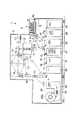
図1には、この発明の実施の形態に係る入金処理機(紙葉類処理装置)1の内部構造を概略的に示してある。この入金処理機1は、複数金種のサイズの異なる複数枚の紙幣を混在させて一括して投入し、全ての紙幣の表裏を揃えてその金種別に分類して集積するためのものであり、特定金種の紙幣についてのみ所定枚数毎に紙帯で施封する機能を有するものである。
【0016】
入金処理機1は、装置の外殻をなす筐体2を有する。筐体2の図中右側にある段部には、複数枚の紙幣Pを面方向に集積した状態で立位でまとめて投入する投入部3が設けられている。紙幣Pは、それぞれ表裏を有するとともにその長手方向に沿って延びた上端および下端を有し、上端或いは下端が下を向く姿勢で投入部3を介して投入される。投入部3は、全ての紙幣Pをその上端或いは下端に当接して整位するステージ3aを有する。投入部3の図中右端にはステージ3aに対して鉛直方向に立設されたバックアッププレート4が設けられている。このバックアッププレート4は、ばね5の付勢力によってステージ3aに沿って図中左方向に移動可能に設けられている。
【0017】
投入部3に立位で投入された複数枚の紙幣Pは、バックアッププレート4によってその面方向に付勢され、図中左方向に移動される。そして、図中左端にある紙幣Pが投入部3の図中左側に互いに上下に隣接した状態で配置された2組の取出しローラ6(取出し部)に押し付けられる。取出しローラ6を所定方向に回転することにより、投入部3に立位で投入された複数枚の紙幣Pのうち左端にある紙幣Pから順に搬送路7上に取り出される。搬送路7上に取出される紙幣Pは、その上端或いは下端を先頭にして短手方向に取出される。このとき、各紙幣の表裏はばらばらの状態となっている。本実施の形態では、投入部3から取出される紙幣Pの取出し方向は下向きとなっている。
【0018】
搬送路7は、搬送路7の上下でそれぞれ搬送方向に沿って無端走行可能に張設された搬送ベルト8、9によって規定されている。各搬送ベルト8、9は、幅方向(紙面方向)に延設された複数のローラ10に巻回されている。搬送路7には、取出された紙幣Pのシフトとスキューを自動補正する姿勢補正装置(後で詳細に説明する)11が設けられている。
【0019】
これらの搬送ベルト8、9によって上方に折り曲げられた搬送路7の先には、紙幣Pの金種、表裏、天地、汚れや破損の有無等の特徴を検知する検知部12が配設されている。検知部12は、搬送路7を搬送される紙幣Pの表面から各種情報を読み取って、読み取った情報を論理演算して基準となる情報と比較し、上述したような紙幣Pの特徴を検知する。
【0020】
ところで、投入部3に投入される紙幣Pは、表裏および天地をバラバラにして投入されるため、搬送路7上に取出され(取込まれ)たとき、その向きが表裏および天地がバラバラな状態になっている。このため、検知部12を通過される複数金種の紙幣Pは、表裏および天地がばらばらな状態となっている。
【0021】
検知部12の下流側に延設された搬送路7上には、検知部12における検知結果に基づいて紙幣Pの搬送方向を選択的に切換えるための複数のゲートG1〜G9が設けられている。
【0022】
検知部12において、2枚取りが判定された紙幣、所定のレベルを超えて大きくスキューしたことが判定された紙幣、或いは再流通可能な正券と判定されなかった損券や偽券などの紙幣(紙幣とは限らない)など、後段の処理が不可能であることが判定された紙幣は、ゲートG1を介して図中右方向に搬送され、リジェクト箱13に排出される。リジェクト箱13には、入金処理機1の筐体2の外部からアクセス可能となっている。
【0023】
一方、検知部12にて処理可能な正常な紙幣であることが判定された紙幣Pは、ゲートG1を介してゲートG2に向けて図中左方向に搬送される。ゲートG1を通過された紙幣Pは、上述したように表裏および天地がバラバラの状態となっている。このように、表裏および天地がばらばらの状態の紙幣Pが、後述する表裏反転機構14を選択的に通過することによって表裏が取り揃えられ、その金種毎に分類されて集積されることになる。本実施の形態では、全ての紙幣Pが基本的に表を上にして集積される。
【0024】
ゲートG2の下流側の搬送路は2方向に分岐されており、ゲートG2を2位置間で選択的に切換えることにより紙幣Pの搬送方向を2方向に選択的に切換えるようになっている。
【0025】
ゲートG2の下流側で分岐された一方の搬送路上には、紙幣Pの表裏を反転させるための表裏反転機構14(表裏反転部)が設けられている。この表裏反転機構14を通る搬送路は、その入口から出口に向けて中心軸の回りで180°回転されたねじり搬送路を形成している。そして、このねじり搬送路に沿って互いに面接する関係で2組の搬送ベルト15、15がねじれた状態で設けられている。
また、ゲートG2の下流側で分岐された他方の搬送路は、ただ単に紙幣Pを通過させるだけの搬送パス16となっている。
【0026】
ゲートG2を介して振り分けられて表裏反転機構14のねじり搬送路を通して搬送される紙幣Pは、表裏反転される。
【0027】
このようにして表裏反転機構14を通過して表裏反転された紙幣P、および表裏反転機構14を通過せずに搬送パス16を通過した紙幣Pは、いずれも合流部18を介してゲートG3に送り込まれる。このとき、ゲートG2を通過してから表裏反転機構14を介して合流部18に至る紙幣Pの処理時間と搬送パス16を通過して合流部18に至る紙幣Pの搬送時間が同じになるように、搬送パス16の長さが設定されている。これにより、表裏反転機構14を通して搬送された紙幣Pと搬送パス16を通過された紙幣Pとが同じタイミングで合流部18を通過することになり、処理形態に拘わらず全ての紙幣Pを同じ条件で処理できる。
【0028】
ゲートG3の下流側の搬送路は2方向に分岐されており、ゲートG3を2位置間で選択的に切換えることにより紙幣Pの搬送方向を2方向に選択的に切換えるようになっている。
【0029】
ゲートG3の下流側で図中右方向に分岐された一方の搬送路は、複数の集積部20〜25の上方で略水平方向に延びた水平搬送路19を形成している。水平搬送路19上には、搬送される紙幣Pを6つの集積部20〜25のうちのいずれか1つに振り分けて集積せしめるための5つのゲートG5〜G9が設けられている。
【0030】
水平搬送路19の最も上流側にあるゲートG5によって選択的に振り分けられた紙幣Pは集積部20に集積され、ゲートG6によって選択的に振り分けられた紙幣Pは集積部21に集積され、ゲートG7によって選択的に振り分けられた紙幣Pは集積部22に集積され、ゲートG8によって選択的に振り分けられた紙幣Pは集積部23に集積され、ゲートG9によって選択的に振り分けられた紙幣Pは集積部24或いは集積部25に集積される。
【0031】
ゲートG3の下流側で図中左方向に分岐された位置には、施封装置26の集積部27が設けられている。施封装置26は、例えば100枚の紙幣Pを集積して紙帯を巻回せしめて施封して紙幣Pの束を形成する。
【0032】
これら施封装置26の集積部27には、紙帯による施封をアサインされた特定金種の紙幣Pが後述するルールに従って送り込まれる(集積される)。一方、特定金種以外の紙幣Pは、上述した集積部20〜25のいずれかに集積される。
【0033】
ゲートG3を介して集積部27で集積された紙幣Pは、供給部28によって施封部29へ送り込まれ、帯供給部29aから供給された紙帯によって施封される。所定枚数毎に施封された紙幣Pの束は、図示しないコンベアを介して装置外へ搬出される。
【0034】
尚、施封部29は、集積部27に集積された所定枚数の紙幣Pを受け取って、その長手方向一側(本実施の形態では入金処理機1のリア側)に片寄った位置で、紙帯をその短手方向に沿って巻回し、所定枚数の紙幣を施封して束を形成する。
【0035】
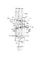
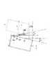
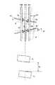
次に、上述した姿勢補正装置11について、図2乃至図4を参照して詳細に説明する。図2には姿勢補正装置11の概略構成を斜視図にして示してあり、図3には姿勢補正装置11の断面図を示してあり、図4には姿勢補正装置11の上面からの図を示してある。
【0036】
姿勢補正装置11は、紙幣Pの搬送方向(図中矢印T方向)に沿って、後述する姿勢検出センサ70、第1及び第2の補正部32、33を有する。姿勢検出センサ70は、搬送路7を介して姿勢補正装置11へ送り込まれる紙幣Pの搬送状態を検出するものである。第1及び第2の補正部32、33は、搬送路7に沿って装置のリア側に立設されたベース板31に取り付けられている。第1及び第2の補正部32、33は、略同一の構成を有するため、ここでは、第1の補正部32について代表して説明し、第2の補正部33についての説明は省略する。
【0037】
第1の補正部32は、細長い板状部材の両端を同じ側に略直角に折り曲げた形状の支持フレーム34を有する。すなわち、支持フレーム34は、搬送路7を介して搬送される最大サイズの紙幣Pの長端辺の長さより少なくとも長いフレーム基部34aと、このフレーム基部34aの両側から略直角に折り曲げられた2つの側板部34b、34bと、を有する。
【0038】
2つの側板部34b、34b間には、軸受36、36を介して、支持アーム(補正アーム)としての駆動軸35が架け渡されている。この駆動軸35には、2つのゴムローラ(補正アームローラ)37a、37bが取り付けられている。これら2つのゴムローラ37a、37bの外周面は、摩擦力を高めるため、ゴム材料によって形成されている。これら2つのゴムローラ37a、37bの上方には、それぞれ対応する2つのゴムローラ38a、38bが転接されている。2つのゴムローラ38a、38bは、軸受39を介して軸40に取り付けられている。
軸40の両端部は、支持フレーム34の側板部34b、34bに形成された長穴41に嵌め込まれ、側板部34b、34bの外側に設けられたバネ42によって下方に付勢されている。つまり、2つのゴムローラ38a、38bがそれぞれ対応する2つのゴムローラ37a、37bに押圧され、これら4つのゴムローラ37a、37b、38a、38bが補正ローラとして機能する。
【0039】
ゴムローラ37a、37b、38a、38bは、搬送路7に沿って姿勢補正装置11を通って延びた3対の搬送ベルト49a、49b、49cの間に入れ子状に配設されている。すなわち、装置のフロント側のゴムローラ対37a、38aは、第1及び第2の搬送ベルト対49a、49bの間に配設され、装置のリア側のローラ対37b、38bは、第1及び第3の搬送ベルト対49a、49c間に配設されている。
【0040】
尚、3組の搬送ベルト対49a、49b、49cは、入金処理機1内を通って延びた搬送路7の全長に亘って設けられ、搬送路7を上下に挟むように対向され、図示しないローラに巻回されて、本発明の搬送部として機能する。
【0041】
より詳細には、中央にある第1の搬送ベルト対49aは、搬送路7の上面側および下面側で搬送路7の中心線7a上を延び、搬送路7を介して互いに面接することで、第2および第3の搬送ベルト対49b、49cとともに搬送路7の上下を規定している。また、補正ローラのうち2つのゴムローラ37a、37bが搬送路7の下面側に配置され、他の2つのゴムローラ38a、38bが搬送路7の上面側に配置され、これら2組のゴムローラ37a、37b、38a、38b間で搬送路7が規定されている。
【0042】
搬送路7の下面側で搬送路7を横切る方向に延設された駆動軸35には、傘歯車50が固定的且つ同軸に取り付けられている。この傘歯車50は、2つのゴムローラ37a、37b間に設けられ、別の傘歯車51が噛み合わされている。別の傘歯車51は、図3に詳細に示すように、略鉛直方向に延設された駆動軸44の上端部に同軸に固設されている。尚、駆動軸44の上端部は、ゴムローラ37a、37bを備えた駆動軸35の中心部に対向されている。
【0043】
駆動軸44は、同軸に設けられた円筒軸43内に挿入され、上部の軸受52、および下部の軸受53により回転自在に保持されている。下部の軸受53は、円筒軸43に固定されたプーリ45の内側に取り付けられている。また、駆動軸44の下端近くには、ワンウエイクラッチ55を介してプーリ64が取り付けられている。プーリ64には、ベルト62及びプーリ63を介してステッピングモータ54の回転軸が接続されている。
【0044】
しかして、ステッピングモータ54が回転駆動されると、プーリ63、ベルト62、及びプーリ64を介して駆動力が伝達され、駆動軸44が回転される。駆動軸44は、ワンウエイクラッチ55の作用により、1方向にだけ回転する。駆動軸44が所定方向に回転すると、その上端に取り付けられた傘歯車51が回転し、傘歯車50を介して駆動軸35が回転される。駆動軸35が回転されると、2つのゴムローラ37a、37bが回転され、これら2つのゴムローラ37a、37bにそれぞれ押圧されて転接された2つのゴムローラ38a、38bも従動回転される。このように4つのゴムローラ37a、37b、38a、38bが回転すると、ゴムローラ間の2つのニップに紙幣Pがクランプされて搬送路7に沿って搬送される。尚、姿勢補正装置11のゴムローラ37a、37b、38a、38bによる紙幣Pのクランプ力が、搬送ベルト49a〜49cによる紙幣Pの挟持力よりも強くなるように、バネ42の強さが設定されている。
【0045】
一方、円筒軸43は、軸受57を介して、略円筒形のハウジング56に回転自在に保持されている。円筒軸43の上端部は、2つのネジ43aにより、支持フレーム34のフレーム基部34aの中心部に固定されている。円筒軸43の下端部に固設されたプーリ45には、ベルト46、プーリ47を介してステッピングモータ48の回転軸が接続されている。円筒軸43を回転自在に保持したハウジング56は、略矩形板状のプレート58を介して、ベース板31に固定されている。プレート58は、ベース板31に対して片持ち梁状態で固定されている。
【0046】
また、ベース板31には、第1の補正部32のホーム位置を検知するためのセンサ59aが設けられている。支持フレーム34には、その回転の途中でセンサ59aの光を遮光する被検出体60が突設されている。つまり、被検出体60がセンサ59aの光を遮った時点でステッピングモータ48の回転を停止することにより、第1の補正部32がホーム位置に配置されることになる。ホーム位置とは、ゴムローラ37a、37b、38a、38bの回転軸が搬送方向と直交(交差)する姿勢を言う。
【0047】
さらに、ベース板31には、センサ59aの他に、第1の補正部32がホーム位置から両方向に所定角度ずつ回転したとき被検出体60を検出する2つのセンサ59b、59c(図4参照)が取り付けられている。これら2つのセンサ59b、59cは、第1の補正部32の振り切り位置を検出するために設けられている。振り切り位置とは、第1の補正部32の回転可能範囲の両端位置を言う。尚、これら3つのセンサ59a、59b、59cは、その光を被検出体60が遮ることによりオン、オフされるフォトインタラプタ等により構成されている。
【0048】
しかして、ステッピングモータ48が回転駆動されると、プーリ47、ベルト46、及びプーリ45を介して駆動力が伝達され、円筒軸43が回転される。円筒軸43が回転されると、円筒軸43の上端部に固設された支持フレーム34が回転され、すなわち第1の補正部32の駆動軸35が回転(回動)され、ゴムローラ37a、37b、38a、38bの向きが可変される。尚、第1の補正部32の駆動軸35の回転位置は、被検出体60を中央のセンサ59aが検出した時点をホーム位置とし、その位置からステッピングモータ48のステップ数を制御することにより任意の位置に調節されるようになっている。
【0049】
上記第2の補正部33の搬送路7上には、センサ82が設けられている。このセンサ82は、第1の補正部32を通過した当該紙幣Pの先端がセンサ82を通過したタイミング、すなわち当該紙幣Pが第2の補正部33のゴムローラ37a、38aと、37b、38bとで挟持拘束されたタイミングを検出するためのセンサである。
【0050】
姿勢検出センサ70は、図5に示すように、搬送路7の上方に設けられたLEDなどの発光素子71、およびこの発光素子71に対応して搬送路7の下方に設けられたフォトダイオードなどの受光素子72を有する。発光素子71は搬送方向と直交する幅方向(紙面方向)に複数個並設され、受光素子72も同じ方向に同じ数だけ並設されている。これら複数の発光素子71および受光素子72は、その複数の光軸が搬送路7を通過する通過位置(図4参照)が搬送方向Tと直交する方向に一列に並ぶように位置決めされている。しかして、搬送路7を介して搬送された紙幣Pにより光が遮断されることにより紙幣Pを検出するようになっている。
【0051】
また、姿勢検出センサ70は、搬送路7の下方に設けられた複数の発光素子73を有する。複数の発光素子73は、上述した受光素子72と平行に同じ数だけ並設され、受光素子72とユニット化されている。これら発光素子73から発せられた光は、搬送路7を介して搬送される紙幣Pの下面に当たって反射され、対応する受光素子72に導かれるようになっている。
【0052】
つまり、姿勢検出センサ70は、搬送路7を介して搬送される紙幣Pによって光が遮断されることで、紙幣Pの搬送方向先端、すなわち紙幣Pの一方の長端辺を検出する。そして、この検出結果に基づいて、姿勢補正制御部97にて当該紙幣Pの長端辺の長さ、スキュー角度、およびシフト量が算出される。
【0053】
また、姿勢検出センサ70は、紙幣Pによって反射される反射光に基づいて、反射パターンを検出し、その模様から、紙幣Pの金種、表裏および天地に関する向き、折れ、切れ、欠けなどを検出する。
【0054】
尚、本実施の形態では、姿勢検出センサ70は、搬送路7の中心線7aを中心にして対象をなすように2つの部分に分割されている。
【0055】
図6には、上述した入金処理機1の動作を制御する制御系のブロック図を示してある。
この入金処理機1の制御系は、制御部90、メモリ91、判定部92、取出し制御部93、搬送制御部94、ゲート制御部95、施封制御部96、姿勢補正制御部97を有する姿勢補正装置11により構成されている。
【0056】
制御部90は、予め設定した動作プログラムに従って装置の全体動作を制御する。
【0057】
メモリ91は、動作プログラムを記憶したり、データ記憶用に用いられるものである。
判定部92は、検知部12の検知結果に基づいて、当該紙幣Pが再流通可能か否かを判定し、当該紙幣Pが施封指定された特定金種の紙幣であるか否かを判定し、当該紙幣Pの表裏および天地を判定するものであり、それぞれの判定結果を制御部90に出力するものである。
【0058】
取出し制御部93は、制御部90の制御により取出しローラ6を回転するものである。
搬送制御部94は、制御部90の制御により搬送路7による搬送ローラを回転するものである。搬送制御部94は、上記3対の搬送ベルト49a、49b、49cを一定速度で移動制御するものである。
【0059】
ゲート制御部95は、制御部90の制御により上記ゲートG1〜G3、G5〜G9の駆動を行うものである。
施封制御部96は、制御部90の制御により施封処理を行うものである。
【0060】
姿勢補正制御部97は、姿勢補正装置11を制御するものである。この姿勢補正制御部97には、姿勢検出センサ70からの検出信号が供給され、第1の補正部32のセンサ59a、59b、59cからの検出信号が供給され、第2の補正部33のセンサ59a、59b、59cからの検出信号が供給され、センサ82からの検出信号が供給されている。
【0061】
また、姿勢補正制御部97には、第1の補正部32のステッピングモータ48、54を回転する駆動回路101、102、第2の補正部33のステッピングモータ48、54を回転する駆動回路103、104が接続されている。
【0062】
姿勢補正制御部97は、姿勢検出センサ70からの検出信号により、図4に示すように、搬送路7を介して姿勢補正装置11へ送り込まれる紙幣Pの搬送状態としてのスキュー量(紙幣Pの搬送方向の傾き量、スキュー角度α[°])αと搬送路7の中心位置(中心線、所定位置)7aからの位置ずれ量ΔS[mm]と紙幣Pの搬送方向の(紙幣Pの短端辺の長さ[mm])lを判断するものである。
【0063】
姿勢補正制御部97は、姿勢検出センサ70からの検知信号により、上記搬送される紙幣Pの搬送位置ずれ量、スキュー量、紙幣Pの搬送方向の長さを判断するものである。姿勢補正制御部97は、第1の補正部32のセンサ59a、59b、59cの検知出力により、第1の補正部32の位置つまり上記駆動軸35の現在の位置を判断するものである。姿勢補正制御部97は、第2の補正部33のセンサ59a、59b、59cの検知出力により、第2の補正部33の位置つまり上記駆動軸35の現在の位置を判断するものである。
【0064】
姿勢補正制御部97は、紙幣Pの搬送位置ずれ量、スキュー量、紙幣Pの搬送方向の長さに基づいて、紙幣Pの搬送位置ずれ量、スキュー量、紙幣Pの搬送方向の長さと上記第1の補正部32のゴムローラ37a、37bの間隔をパラメータとした上記第1の補正部32の駆動軸35の駆動角度を算出し、この算出した駆動角度と上記第1の補正部32の駆動軸35の現在の位置とに基づいて、上記駆動軸35を回転制御するものである。
【0065】
姿勢補正制御部97は、上記算出した駆動角度に基づく上記第1の補正部32のゴムローラ37a、37bの回転数Qを算出し、この算出した回転数Qでステッピングモータ54を回転制御することにより、上記第1の補正部32のゴムローラ37a、37bを回転するものである。
【0066】
上記搬送ベルト49a、49b、49cによる紙幣Pの搬送速度(ベルトの周速)をY(図7参照)、上記駆動角度をθ(図7参照)、上記ゴムローラ37a、37bの半径をr、円周率をπとした際に、
上記ゴムローラ37a、37bの回転数Qが、
Q=Ycosθ/2πr
により算出される。
【0067】
姿勢補正制御部97は、上記検出したスキュー量に基づく上記第2の補正部33のゴムローラ37a、37bの回転数Q’を算出し、この算出した回転数Q’でステッピングモータ54を回転制御することにより、上記第2の補正部33のゴムローラ37a、37bを回転するものである。
【0068】
上記搬送ベルト49a、49b、49cによる紙幣Pの搬送速度(ベルトの周速)をY、上記スキュー量をα、上記ゴムローラ37a、37bの半径をr、円周率をπとした際に、
上記ゴムローラ37a、37bの回転数Q’が、
Q’=Ycosα/2πr
により算出される
。 姿勢補正制御部97は、センサ82により搬送される紙幣Pの先端を検知した際に、スキュー角度に基づいて、補正する角度分、ステッピングモータ48を回転制御することにより、上記第2の補正部33の駆動軸35を回転するものである。すなわち、第1の補正部32を通過した当該紙幣Pの先端がセンサ82を通過したタイミング、すなわち当該紙幣Pが第2の補正部33のゴムローラ37a、38aと、37b、38bとで挟持拘束されたタイミングで、第2の補正部33の駆動軸35を角度α分、図中矢印83の方向に回転させるものである。このように、第2の補正部33のゴムローラ37a、38aと、37b、38bとで当該紙幣Pをクランプした状態で、第2の補正部33の駆動軸35が回転することで、当該紙幣Pの傾きが補正される。
[第1の実施形態]
次に、上記のように構成された姿勢補正装置11の第1の補正部32による補正動作について、図4、図7と図8に示すフローチャートを参照して説明する。
【0069】
図7には、第1の補正部32を搬送路7の上方から見た概略図を示してある。
【0070】
すなわち、搬送路7により第1の補正部32に搬送される紙幣Pに図7に実線で示す程度のスキューαおよびシフトΔSを生じているものとする。
【0071】
この状態において、搬送路7上の図示しないセンサの検知信号により、制御部90が紙幣P(Pa)の第1の補正部32への送り込みを判断した際、制御信号を姿勢補正制御部97に出力する。これにより、姿勢補正制御部97は、第1の補正部32のステッピングモータ54を駆動制御する(ST1)。この駆動により第1の補正部32のゴムローラ37a、37b、38a、38bが搬送ベルト対49a〜49cの周速と等しい周速で搬送方向に回転される。
【0072】
また、上記紙幣Pが姿勢検出センサ70を通過することにより、姿勢検出センサ70からの検出信号が姿勢補正制御部97に出力される。
【0073】
姿勢補正制御部97は、姿勢検出センサ70からの検出信号により、図7に示すように、搬送路7を介して姿勢補正装置11へ送り込まれる紙幣Pの搬送状態としてのスキュー量(紙幣Pの搬送方向の傾き量、スキュー角度α[°])αと搬送路7の中心位置(所定位置)7aからの位置ずれ量ΔS[mm]と紙幣Pの搬送方向の長さ(紙幣Pの短端辺の長さ[mm])lを判断する(ST2)。
【0074】
姿勢補正制御部97は、上記判断した紙幣Pの搬送位置ずれ量、スキュー量、紙幣Pの搬送方向の長さをパラメータとして、tanθ=ΔS/lなる駆動角度θが算出される(ST3)。
【0075】
ついで、姿勢補正制御部97は、この算出した駆動角度θと上記第1の補正部32の駆動軸35の現在の位置とに基づいて、第1の補正部32のステッピングモータ48を駆動制御する(ST4)。この駆動により上記駆動軸35を補正する角度の位置まで回転(回動)する。
【0076】
また、この際姿勢補正制御部97は、この算出した駆動角度θに基づいて、上記ゴムローラ37a、37bの回転数Qを
Q=Ycosθ/2πr
により算出する(ST5)。
【0077】
姿勢補正制御部97は、この算出した回転数Qに対応する回転数でステッピングモータ54を回転制御する(ST6)。この駆動により、上記第1の補正部32のゴムローラ37a、37bを回転する
この結果、紙幣P(Pb)が上記第1の補正部32を通過する際、紙幣Pの移動速度とゴムローラ37a、37b、38a、38bの紙幣Pの搬送方向に対する速度(ゴムローラの周速のうち紙幣Pの搬送方向の速度成分)とが上記第1の補正部32の駆動軸35の駆動角度に係らず一致し、この状態で位置ずれを補正する移動が行われる。この際、駆動軸35の搬送方向に交差する方向に対する角度とゴムローラ37a、37b、38a、38bにより紙幣Pが搬送される時間とにより、上記補正量ΔSが決定されている。
【0078】
上述したように姿勢補正制御部97にて当該紙幣Pのシフト量ΔS、スキュー角度α、および短端辺の長さlが判断されると、続いて、 tanθ=ΔS/lなるθが姿勢補正制御部97にて算出される。そして、このθの角度だけ、図4に矢印81として示すように、第1の補正部32の駆動軸35を回転させるように、ステッピングモータ48を回転駆動する。このとき、第1の補正部32の円筒軸43と軸44が逆方向に回転するが、ワンウエイクラッチ55が空転するために、第1の補正部32の回転速度は変化しない。
【0079】
また、θの角度に伴い紙幣Pの搬送速度(搬送ベルト49a〜49c)に対してゴムローラ37a、37b、38a、38bによる紙幣Pの搬送方向の速度が相対的に低下するのを、実際の回転数を速くすることにより抑制することができる。すなわち、第1の補正部32の駆動軸35の角度ごとに、上記回転数を補正する。
【0080】
この状態で第1の補正部32に紙幣Pが送り込まれると、当該紙幣Pは、ゴムローラ37a、37b、38a、38bによって挟持拘束されつつ搬送される。
ゴムローラ37a、37b、38a、38bによって搬送される紙幣Pは、搬送路7の中心線7aに対して、θだけシフトした方向T’に指向される。このとき、当該紙幣Pは、そのスキュー角αを維持したまま矢印T’方向に指向され、幅方向の位置ずれだけが補正される。
【0081】
この際、紙幣Pの移動速度とゴムローラ37a、37b、38a、38bの紙幣Pの搬送方向に対する速度とが上記第1の補正部32の駆動軸35の駆動角度に係らず一致し、速度の違いによる紙幣Pの傾き(姿勢)の変更が起こらず、精度の高い補正を行うことが可能となる。
【0082】
たとえば、図9に示すように、駆動軸35の振り角度は紙幣突入時(t1,t2,t3、紙幣Pの搬送タイミング)に補正角(駆動角度)まで駆動を終えていることが前提で、更に突入時点でゴムローラ37a、37b、38a、38bの垂直方向の搬送速度を駆動軸35の振り角度毎に補正する。
【0083】
このようにゴムローラ37a、37b、38a、38bの回転速度を振り角毎に合わせ込むことで紙幣Pの傾き(姿勢)を変えずに精度の高い補正を行うことが可能となる。
【0084】
また、姿勢補正制御部97は、上記判断した紙幣Pのスキュー量(角度)αに基づいて、第2の補正部33のステッピングモータ48を駆動制御する(ST7)。この駆動により第2の補正部33の駆動軸35を傾き補正する角度の位置まで回転(回動)する(矢印83の逆方向)。
【0085】
姿勢補正制御部97は、スキュー量(角度)αに基づいて、第2の補正部33のゴムローラ37a、37bの回転数Q’を「Q’=Ycoα/2πr」により算出する(ST8)。
【0086】
姿勢補正制御部97は、この算出した回転数Q’に対応する回転数でステッピングモータ54を回転制御する。この駆動により、上記第2の補正部33のゴムローラ37a、37bを回転する
この結果、紙幣P(Pb)が上記第2の補正部32に進入する際、紙幣Pの移動速度とゴムローラ37a、37b、38a、38bの紙幣Pの搬送方向に対する速度(ゴムローラの周速のうち紙幣Pの搬送方向の速度成分)とが上記第2の補正部33の駆動軸35の駆動角度に係らず一致する。
【0087】
この状態において、姿勢補正制御部97は、センサ82からの検知信号により、紙幣Pを受取ったことを判断する(ST9)。
【0088】
この判断により、姿勢補正制御部97は、第2の補正部33のスキュー量(角度)が0になるまでステッピングモータ48を駆動する(ST10)。この駆動により第2の補正部33の駆動軸35を傾きが補正される角度0の位置まで回転(回動)する(矢印83の方向)。
【0089】
これにより、姿勢補正制御部97は、第2の補正部33のステッピングモータ54を駆動制御し、搬送ベルト対49a〜49cの周速と等しい周速でゴムローラ37a、37b、38a、38bを回転する。すなわち、ゴムローラ37a、37bの回転数を搬送速度Yに戻す(ST11)。
【0090】
この結果、第1の補正部32を通過した当該紙幣Pの先端がセンサ82を通過したタイミング、すなわち当該紙幣P(Pc)が第2の補正部33のゴムローラ37a、37b、38a、38bで挟持拘束されたタイミングで、第2の補正部33をαだけ図中矢印83の方向に回転させる。このように、第2の補正部33のゴムローラ37a、37b、38a、38bが当該紙幣Pをクランプした状態で、第2の補正部33が回転することで、当該紙幣P(Pd)の傾きが補正される。
【0091】
以上の一連の制御動作で、シフトとスキューが連続的に補正された紙幣Pは、搬送姿勢が補正されてセンタリングされた正しい姿勢の紙幣Pとして、下流側の検知部12へ搬送される。
【0092】
また、姿勢補正装置11に送り込まれる紙幣Pのうち、スキューやシフトのない紙幣Pについては、第1及び第2の補正部32、33の駆動軸35、35を回転させないことで、正しい姿勢を保ったまま直後の検知部12へ搬送される。尚、本実施の形態において、正しい姿勢とは、紙幣Pの長手方向に沿った一端辺が搬送路7の中心線7aと直交し、且つ紙幣Pの中心が中心線7a上に位置する基準姿勢を言う。
【0093】
上記したように、紙幣Pが第1の補正部及び第2の補正部の補正アームローラに入り込んだ時に速度が瞬時に低下し衝突現象を起こして紙幣の姿勢を変えてしまう(スキューさせてしまう)という問題を回避し、紙幣の姿勢を限りなく保ちつつ高い制度で補正を行うことが可能になる
[第2の実施形態]
次に、姿勢補正装置11において、先行する紙幣Pと現行の紙幣Pとのギャップ(間隔)に基づいて、補正処理を行うか、補正処理を禁止する処理について説明する。
【0094】
この場合、姿勢補正制御部97は、姿勢検出センサ70からの検出信号に基づいて、先行する紙幣Pの後端と現行の紙幣Pの先端を判断し、この判断に基づいて先行する紙幣Pと現行の紙幣Pとのキャップ(間隔)を判断するようになっている。
【0095】
また、姿勢検出センサ70からの検出信号の代りに、搬送路7上の姿勢補正制御部97よりも上流に設けられている搬送検知用のセンサ(図示しない)からの検知信号を用いるようにしても良い。
【0096】
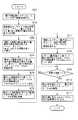
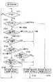
次に、姿勢補正の判定動作について、図10に示すフローチャートを参照しつつ説明する。
【0097】
まず、図11に示すように、先行する紙幣P1と現行の紙幣P2とがギャップ(間隔)g1をもって搬送される場合について説明する。
【0098】
姿勢補正制御部97は、姿勢検出センサ70からの検出信号により、先行する紙幣P1の後端と現行の紙幣P2の先端を判断し、先行する紙幣P1の後端と現行の紙幣P2の先端とにより、先行する紙幣P1と現行の紙幣P2のギャップ(間隔)g1を判断する(ST11)。ついで、姿勢補正制御部97は、このギャップg1が補正可能値よりも大きいか、同じか、小さいかを判断する(ST12)。この際、姿勢補正制御部97は、このギャップg1が補正可能値よりも小さいと判断し、先行する紙幣P1と現行の紙幣P2に対する姿勢補正の禁止を判断し(ST13)、第1の補正部32の駆動軸35と第2の補正部33の駆動軸35とを平行位置に設定する。
【0099】
この結果、先行する紙幣P1と現行の紙幣P2は、シフトとスキューを補正せずに姿勢補正装置11を通過する。
【0100】
次に、図12に示すように、先行する紙幣P1と現行の紙幣P2とがギャップ(間隔)g2をもって搬送される場合について説明する。
【0101】
姿勢補正制御部97は、姿勢検出センサ70からの検出信号により、先行する紙幣P1の後端と現行の紙幣P2の先端を判断し、先行する紙幣P1の後端と現行の紙幣P2の先端とにより、先行する紙幣P1と現行の紙幣P2のギャップ(間隔)g2を判断する(ST11)。ついで、姿勢補正制御部97は、このギャップg2が補正可能値よりも大きいか、同じか、小さいかを判断する(ST12)。この際、姿勢補正制御部97は、このギャップg2が補正可能値よりも大きい(同じ)と判断し、先行する紙幣P1と現行の紙幣P2に対する姿勢補正の許可を判断し(ST14)、第1の補正部32によるシフト補正と第2の補正部33によるスキュー補正が行われる。
【0102】
図11はショートピッチで取込まれた紙幣Pが姿勢補正装置11に送り込まれた場合の図を示す。
【0103】
位置ずれ補正は、紙幣Pの先端が位置ずれ補正アームとしての駆動軸35に入り込むまでに、補正角分の駆動を行う。ついで、ゴムローラにより紙幣Pを傾けた角度方向の斜めに搬送することで、姿勢を変えずに位置ずれを補正する。この後、紙幣Pがゴムローラ上にある間、駆動軸35は補正角度をキープする。
【0104】
このため、駆動軸35を駆動するタイミングは先行の紙幣P1の後端から現行(後続)の紙幣P2の先端の間のギャップで行う。
【0105】
接近した紙幣Pを補正する限界は駆動軸35の動作時間で決定する。駆動軸35は紙幣1枚に1回だけ駆動するため補正後は後続紙幣Pが来るまで補正した時点の振り角のままで保持する。
【0106】
この限界を超えた接近紙幣Pは補正できないため補正を禁止する必要がある。
【0107】
接近紙幣P1,P2が流れた場合、紙幣P1を補正するとギャップg1のように補正限界を超えていた場合に紙幣P2を補正できないため、紙幣P1を補正した振り角度のまま紙幣P2を補正せずに通過させてしまう。紙幣P1のセンタからの位置ずれがz1,紙幣P2のセンタからの位置ずれがz2であった場合は、紙幣P1はセンタ位置の補正されP2はz1+z2だけセンタ位置からずれてしまう。
【0108】
図11、図12において、先行の紙幣P1と現行の紙幣P2のギャップg1、g2をチェックし、図11に示すように、ギャップg1が補正限界を超えていた場合には、先行の紙幣P1に対して第1の補正部32の駆動軸35を平行位置に駆動し、接近紙幣P1,P2とも補正を禁止させることで後続紙幣Pの位置ずれを大きく外してしまうことを防止する。
【0109】
したがって、接近して取り出された紙幣2枚を補正限界を超えて接近した紙幣は補正できないため補正を禁止するが、先頭紙幣を補正すると後続の接近紙幣のを大きくセンタから位置ずれさせてしまうことでジャムの要因になっていた問題を解決することが可能になる。
[第3の実施形態]
次に、姿勢補正装置11において、先行する紙幣Pと現行の紙幣Pとのギャップ(間隔)と先行する紙幣P1と現行の紙幣P2の位置ずれの方向に基づいて、補正処理を行うか、補正処理を禁止する処理について説明する。
【0110】
この場合、姿勢補正制御部97は、姿勢検出センサ70からの検出信号に基づいて、先行する紙幣P1の後端と現行の紙幣P2の先端を判断し、この判断に基づいて先行する紙幣P1と現行の紙幣P2とのキャップ(間隔)を判断するようになっている。
【0111】
また、姿勢補正制御部97は、姿勢検出センサ70からの検出信号に基づいて、位置ずれ量ΔSを判断するようになっている。
【0112】
次に、補正動作について、図13に示すフローチャートを参照しつつ説明する。
【0113】
まず、姿勢補正制御部97は、姿勢検出センサ70からの検出信号により、先行する紙幣P1の後端と現行の紙幣P2の先端を判断し、先行する紙幣P1の後端と現行の紙幣P2の先端とにより、先行する紙幣P1と現行の紙幣P2のギャップ(間隔)を判断する(ST21)。ついで、姿勢補正制御部97は、このギャップが補正可能値よりも大きいか、同じか、小さいかを判断する(ST22)。この際、姿勢補正制御部97は、このギャップが補正可能値よりも小さいと判断した場合、先行する紙幣P1に位置ずれが有るか否かを判断する(ST23)。
【0114】
この結果、姿勢補正制御部97は、先行する紙幣P1に位置ずれがなく、搬送路7の中心に位置していると判断した場合、先行する紙幣P1に対する姿勢補正の許可を判断し現行の紙幣P2に対する姿勢補正の禁止を判断する(ST24)。
【0115】
これにより、先行する紙幣P1は第1の補正部32によるシフト補正が行われずに、第2の補正部33によるスキュー補正が行われる。現行の紙幣P2は第1の補正部32によるシフト補正、第2の補正部33によるスキュー補正が行われずに(変化なしに)通過する。
【0116】
また、上記ステップ23で、先行する紙幣P1に位置ずれがあると判断した場合、姿勢補正制御部97は、先行する紙幣P1と現行の紙幣P2の位置ずれの方向と量が同一か否かを判断する(ST25)。
【0117】
この結果、姿勢補正制御部97は、先行する紙幣P1と現行の紙幣P2の位置ずれの方向と量が同一と判断した場合、先行する紙幣P1に対する姿勢補正の許可を判断し現行の紙幣P2に対する姿勢補正の禁止を判断する(ST24)。
【0118】
これにより、先行する紙幣P1は第1の補正部32の駆動軸35の回動によるシフト補正が行われ、第2の補正部33によるスキュー補正が行われる。現行の紙幣P2は第1の補正部32の駆動軸35が先行する紙幣P1を処理したまま保持されていることによりシフト補正が行われ、第2の補正部33によるスキュー補正が行われずに通過する。
【0119】
また、上記ステップ25で、先行する紙幣P1と現行の紙幣P2の位置ずれの方向と量が同一でないと判断した場合、姿勢補正制御部97は、先行する紙幣P1の位置ずれ方向が右か左かを判断する(ST26)。
【0120】
ついで、姿勢補正制御部97は先行する紙幣P1の位置ずれ方向が右と判断した場合に、現行の紙幣P2が先行する紙幣P1よりもさらに右へ位置ずれかを判断する(ST27)。
【0121】
この判断の結果、姿勢補正制御部97は、現行の紙幣P2が先行する紙幣P1よりもさらに右へ位置ずれと判断した場合に、先行する紙幣P1に対する姿勢補正の許可を判断し現行の紙幣P2に対する姿勢補正の禁止を判断する(ST24)。
【0122】
これにより、先行する紙幣P1は第1の補正部32の駆動軸35の回動によるシフト補正が行われ、第2の補正部33によるスキュー補正が行われる。現行の紙幣P2は第1の補正部32の駆動軸35が先行する紙幣P1を処理したまま保持されていることによりシフト補正が行われ、第2の補正部33によるスキュー補正が行われずに通過する。
【0123】
また、上記ステップ27で、現行の紙幣P2が先行する紙幣P1よりもさらに右へ位置ずれでないと判断した場合に、先行する紙幣P1と現行の紙幣P2に対する姿勢補正の禁止を判断し(ST28)、第1の補正部32の駆動軸35と第2の補正部33の駆動軸35とを平行位置に設定する。
【0124】
この結果、先行する紙幣P1と現行の紙幣P2は、シフトとスキューを補正せずに姿勢補正装置11を通過する。
【0125】
また、上記ステップ26で、姿勢補正制御部97は先行する紙幣P1の位置ずれ方向が左と判断した場合に、現行の紙幣P2が先行する紙幣P1よりもさらに左へ位置ずれかを判断する(ST29)。
【0126】
この判断の結果、姿勢補正制御部97は、現行の紙幣P2が先行する紙幣P1よりもさらに左へ位置ずれと判断した場合に、先行する紙幣P1に対する姿勢補正の許可を判断し現行の紙幣P2に対する姿勢補正の禁止を判断する(ST24)。
【0127】
これにより、先行する紙幣P1は第1の補正部32の駆動軸35の回動によるシフト補正が行われ、第2の補正部33によるスキュー補正が行われる。現行の紙幣P2は第1の補正部32の駆動軸35が先行する紙幣P1を処理したまま保持されていることによりシフト補正が行われ、第2の補正部33によるスキュー補正が行われずに通過する。
【0128】
また、上記ステップ29で、現行の紙幣P2が先行する紙幣P1よりもさらに左へ位置ずれでないと判断した場合に、姿勢補正制御部97は、先行する紙幣P1と現行の紙幣P2に対する姿勢補正の禁止を判断し(ST28)、第1の補正部32の駆動軸35と第2の補正部33の駆動軸35とを平行位置に設定する。
【0129】
この結果、先行する紙幣P1と現行の紙幣P2は、シフトとスキューを補正せずに姿勢補正装置11を通過する。
【0130】
また、上記ステップ22でギャップが補正可能値よりも大きい(同じ)と判断した場合、姿勢補正制御部97は、先行する紙幣P1と現行の紙幣P2に対する姿勢補正の許可を判断し(ST30)、第1の補正部32によるシフト補正と第2の補正部33によるスキュー補正が行われる。
【0131】
上記したように、図11において、仮に先行の紙幣P1がセンタより右にZ1位置ずれしていた場合に現行の紙幣P2の計測が終了するとギャップg1とセンタ位置ずれの結果が求まる。ギャップが補正可能値の場合は先行の紙幣P1、現行の紙幣P2とも補正を許可して補正します。
【0132】
図のようにギャップg1が補正限界を超えて小さかった場合は、先行の紙幣P1の位置ずれが右にZ1ずれていた場合、先行の紙幣P1を補正するとセンタ位置にするため駆動軸(補正アーム)35をθの角度で左に傾けることになる。
【0133】
図のように先行の紙幣P1が右にZ1位置ずれしていた場合、このZ1の位置を基準に現行の紙幣P2が右に位置ずれしていた時はフローチャートのステップ24の処理で先行の紙幣P1は補正し、現行の紙幣P2は先行の紙幣P1を補正したアーム角のまま補正しない処理を行うことで、現行の紙幣P2はZ1との差分だけセンタから右に補正される。
【0134】
逆にZ1の位置より現行の紙幣P2が左に位置ずれしていた場合(図11)は左に位置ずれしている現行の紙幣P2を更に左に位置ずれさせてしまうためフローチャートのステップ28の処理で、補正アームを平行位置に設定して先行紙幣と現紙幣を補正しないで通過させる処理を行う。
【0135】
先行紙幣P1が左に位置ずれしていた場合は同様に上述処理の考え方の左右を入換えて処理を行う。
【0136】
【発明の効果】
以上詳述したように、この発明によれば、紙葉類の搬送方向に交差する位置ずれ量に基づく角度で紙葉類を移動する位置補正ローラの紙葉類の搬送方向に対する速度を、搬送手段による搬送速度と一致させることができ、位置補正ローラにより紙葉類の姿勢を変化させてしまうことを防止できる紙葉類処理装置を提供できる。
【0137】
また、姿勢補正の限界を超えて接近した紙葉類に対する姿勢の補正を禁止することができ、後続の紙葉類の位置ずれの拡大を防止できる紙葉類処理装置を提供できる。
【図面の簡単な説明】
【図1】この発明の実施形態を説明するための入金処理機の内部構造を概略的に示す図。
【図2】投入部から取出された紙幣の表裏および天地に関する向きを説明するための図。
【図3】姿勢補正装置の内部構成を説明するための斜視図。
【図4】姿勢補正装置の内部構成を説明するための断面図。
【図5】姿勢補正装置の構成を説明するための上面からの図。
【図6】入金処理機の動作を制御する制御系のブロック図。
【図7】姿勢補正装置の第1の補正部による補正動作を説明するための図。
【図8】姿勢補正装置の第1の補正部による補正動作を説明するためのフローチャート。
【図9】姿勢補正装置による補正処理を説明するための図。
【図10】姿勢補正の判定動作を説明するためのフローチャート。
【図11】姿勢補正装置に連続して搬送される紙幣の状態を説明するための図。
【図12】姿勢補正装置に連続して搬送される紙幣の状態を説明するための図。
【図13】姿勢補正の判定動作を説明するためのフローチャート。
【符号の説明】
θ…駆動角度、P…紙幣、Y…搬送方向、α…スキュー量、ΔS…シフト量、1…入金処理機、7…搬送路、7a…中心線、11…姿勢補正装置、12…検知部、32…第1の補正部、33…第2の補正部、35…駆動軸、37a、37b、38a、38b…ゴムローラ、48、54…ステッピングモータ、59a、59b、59c、82…センサ、70…姿勢検出センサ、90…制御部、91…メモリ、91a…駆動角度テーブル、92…判定部、93…制御部、94…搬送制御部、95…ゲート制御部、96…施封制御部、97…姿勢補正制御部、101、102、103、104…駆動回路。[0001]
BACKGROUND OF THE INVENTION
The present invention relates to a paper sheet processing apparatus that detects and processes features from paper sheets taken out on a transport path, and in particular, takes out and transports a plurality of banknotes one by one on a transport path, The present invention relates to a deposit processing machine that detects features such as orientation and aligns the front and back sides and the top and bottom and accumulates them in denominations.
[0002]
[Prior art]
Conventionally, as a paper sheet processing apparatus, for example, a plurality of banknotes of a plurality of denominations are mixed and put together, the inserted banknotes are picked up one by one on a conveyance path, their characteristics are detected, and their front and back and top and bottom are aligned. There are known deposit processing machines that accumulate by type.
[0003]
[Problems to be solved by the invention]
However, since the size of the banknote varies depending on the denomination and the position of the characteristic part of the banknote varies depending on the denomination, depending on the arrangement position of the detection part for detecting the characteristic, the characteristic part is not opposed to the characteristic part. A denomination that cannot be detected with high accuracy occurs. For this reason, in the conventional apparatus, many detection parts are arrange | positioned in the width direction of a conveyance path, and it has enabled it to detect the characteristic of a banknote now with high precision, even if the characteristic part passes any position.
Therefore, since it is necessary to provide such a large number of detection units, there is a problem that the apparatus configuration becomes complicated and the manufacturing cost of the apparatus increases.
[0004]
Further, in the conventional apparatus, when the banknote transport posture is a posture (skew) inclined with respect to the transport path and / or a posture (shift) offset in the width direction of the transport path, the posture failure is thus caused. The bill as it is is conveyed through the conveyance path, and there is a problem that the feature detection accuracy of the bill in the detection unit further decreases.
[0005]
Therefore, there has been proposed one that corrects the misalignment of banknotes with a correction roller before correcting the skew. For example, it is proposed in Japanese Patent Application No. 2000-280843.
[0006]
That is, a Swing Arm Roller (hereinafter abbreviated as SAR) method has been proposed as a method for correcting a shift of a bill that is shifted by a certain distance from the transport center in the transport device. In the SAR method, the rotation axis (drive shaft) of the SAR is set at the transport center of the apparatus and perpendicular to the transport plane. At the time of shift correction, this SAR is held at an angle around the rotation axis, and the shift is corrected while the bill passes through the SAR. For this reason, it has been proposed to set the angle of the SAR relative to the transport direction so that the banknote shift amount becomes 0 at the moment when the banknote passes through the SAR and no longer receives any force from the SAR.
[0007]
That is, in the method of correcting the misalignment of banknotes, the misalignment amount (distance) from the center of the measured banknote is added to the length of the banknote in the short direction, and the correction arm is tilted to correct the misalignment. The positional deviation is corrected while maintaining the skew angle.
[0008]
However, in this proposal, correction is performed while the correction arm roller is continuously rotated at a constant rotation of the conveyance speed. In this method, when the correction arm is tilted, the speed of the correction arm roller with respect to the conveyance direction decreases according to the inclination angle of the correction arm. There is a problem that the bill may change its posture (tilt).
[0009]
In addition, the posture and the skew are corrected while the swing angle of the misalignment correction arm and the skew correction arm is sequentially shifted to an appropriate value for each banknote taken by the posture correction device.
Each correction arm has an actual operation time, and it is necessary to finish the driving operation up to the correction angle before the bill enters the correction arm to be corrected. Since each correction arm requires time for driving operation, there is a limit that can correct two bills taken close to each other. Since it is not possible to correct banknotes that approach this limit, correction must be prohibited. At this time, when the correction arm is kept at the same position, there is a problem that the positional deviation may be enlarged if the correction arm is tilted.
[0010]
SUMMARY OF THE INVENTION The present invention has been made in view of the above points, and an object of the present invention is to carry the paper sheet in the position correction roller that moves the paper sheet at an angle based on the amount of displacement that intersects the paper carrying direction. It is an object of the present invention to provide a paper sheet processing apparatus that can match the speed with respect to the transport speed of the transport means and prevent the position correction roller from changing the posture of the paper sheet. This makes it possible to perform correction with high accuracy while maintaining the posture of the paper sheet.
[0011]
Another object of the present invention is to provide a paper sheet processing apparatus capable of prohibiting the correction of the posture with respect to a paper sheet approaching beyond the limit of the posture correction and preventing an increase in the positional deviation of the subsequent paper sheet. There is.
[0012]
[Means for Solving the Problems]
The paper sheet processing apparatus according to the present invention includes a transport unit that transports a paper sheet along a transport path, and a direction that is provided on the transport unit and intersects a transport direction of the paper sheet that is transported by the transport unit. A detecting means for detecting the amount of positional deviation, a support arm provided at the rear stage of the detecting means on the conveying means and pivotally supported at the center of the conveying path, and a position correcting roller provided on the supporting arm. The supporting arm based on a moving means for moving the paper sheet conveyed by the conveying means in a direction intersecting the conveying path, and a displacement amount from a predetermined position detected by the detecting means. And a speed component of the peripheral speed of the position correction roller with respect to the conveyance direction of the paper sheet according to a change in the driving angle calculated by the first calculation means. Conveying speed Based on the second calculation means for calculating the same rotation number of the position correction roller and the driving angle calculated by the first calculation means, the support arm of the moving means is rotated, and the second calculation means By rotating the position correction roller of the moving means based on the number of rotations calculated by the calculating means, the paper sheets conveyed by the conveying means are moved in the direction intersecting the conveying path, and the paper sheets Correction means for correcting a positional deviation from a predetermined position.
[0013]
The paper sheet processing apparatus according to the present invention includes a transport unit that transports paper sheets sequentially and sequentially along a transport path, a preceding paper sheet that is sequentially transported by the transport means, and a current paper sheet. Detects the amount of misalignment with respect to either the left or right direction that intersects the transport direction, the tilt amount in the direction that intersects the transport direction of the paper sheet, and the interval between the preceding paper sheet and the current paper sheet And the preceding paper sheet and the current paper conveyed by the conveying means when the interval between the preceding paper sheet detected by the detecting means and the current paper sheet is equal to or greater than a predetermined interval. A first correction unit that corrects a positional shift and a tilt in a direction intersecting the transport direction based on the positional shift amount and the tilt amount detected by the detection unit for each leaf; and the detection Previous and current paper sheets detected by means When spacing is less than a predetermined distance, and a prohibition means for prohibiting the correction of the positional deviation and inclination with respect to the paper sheet and current sheet prior to being conveyed by said conveying means.
[0014]
DETAILED DESCRIPTION OF THE INVENTION
Hereinafter, embodiments of the present invention will be described in detail with reference to the drawings.
[0015]
FIG. 1 schematically shows an internal structure of a deposit processing machine (paper sheet processing apparatus) 1 according to an embodiment of the present invention. The
[0016]
The
[0017]
The plurality of banknotes P placed in the insertion portion 3 in a standing position are urged in the surface direction by the backup plate 4 and moved leftward in the figure. Then, the bill P at the left end in the figure is pressed against two sets of take-out rollers 6 (take-out sections) arranged in the state of being adjacent to each other on the left side of the input section 3 in the figure. By rotating the take-out roller 6 in a predetermined direction, the banknotes P placed at the left end among the plurality of banknotes P placed in the standing position 3 are sequentially taken out onto the
[0018]
The
[0019]
At the tip of the
[0020]
By the way, since the banknote P thrown into the insertion part 3 is thrown into the front and back and the top and bottom apart, when it is taken out (taken in) on the
[0021]
A plurality of gates G <b> 1 to G <b> 9 for selectively switching the conveyance direction of the banknote P based on the detection result in the
[0022]
Bills such as banknotes that have been determined to be picked by the
[0023]
On the other hand, the banknote P determined to be a normal banknote that can be processed by the
[0024]
The conveyance path on the downstream side of the gate G2 is branched in two directions, and the conveyance direction of the bills P is selectively switched in two directions by selectively switching the gate G2 between two positions.
[0025]
On one conveyance path branched on the downstream side of the gate G2, a front / back reversing mechanism 14 (front / back reversing part) for reversing the front and back of the banknote P is provided. The conveyance path passing through the front / back reversing
Moreover, the other conveyance path branched on the downstream side of the gate G2 is a
[0026]
The banknotes P distributed through the gate G2 and transported through the torsion transport path of the front / back reversing
[0027]
The banknote P that has been turned upside down through the front / back reversing
[0028]
The conveyance path on the downstream side of the gate G3 is branched in two directions, and the conveyance direction of the bills P is selectively switched in two directions by selectively switching the gate G3 between two positions.
[0029]
One conveyance path branched rightward in the figure on the downstream side of the gate G3 forms a
[0030]
The banknotes P that are selectively distributed by the gate G5 located on the most upstream side of the
[0031]
An
[0032]
The banknotes P of a specific denomination assigned with a paper band are sent (accumulated) to the stacking
[0033]
The banknotes P accumulated in the accumulating
[0034]
The sealing
[0035]
Next, the
[0036]
The
[0037]
The
[0038]
A
Both end portions of the
[0039]
The
[0040]
The three pairs of
[0041]
More specifically, the first conveying
[0042]
A
[0043]
The
[0044]
Thus, when the stepping
[0045]
On the other hand, the
[0046]
The
[0047]
Furthermore, in addition to the
[0048]
Thus, when the stepping
[0049]
A
[0050]
As shown in FIG. 5, the
[0051]
In addition, the
[0052]
That is, the
[0053]
In addition, the
[0054]
In the present embodiment, the
[0055]
FIG. 6 is a block diagram of a control system that controls the operation of the
The control system of the
[0056]
The
[0057]
The
The
[0058]
The take-out
The
[0059]
The
The sealing
[0060]
The posture
[0061]
In addition, the posture
[0062]
As shown in FIG. 4, the posture
[0063]
The posture
[0064]
The posture
[0065]
The posture
[0066]
The transport speed (belt peripheral speed) of the bills P by the
The rotation speed Q of the
Q = Ycos θ / 2πr
Is calculated by
[0067]
The posture
[0068]
When the conveyance speed (belt circumferential speed) of the bills P by the
The number of rotations Q ′ of the
Q ′ = Y cos α / 2πr
Calculated by
. The posture
[First Embodiment]
Next, the correction operation by the
[0069]
FIG. 7 is a schematic view of the
[0070]
That is, it is assumed that the skew α and the shift ΔS to the extent shown by the solid line in FIG. 7 are generated in the banknote P conveyed to the
[0071]
In this state, when the
[0072]
Further, when the bill P passes through the
[0073]
As shown in FIG. 7, the posture
[0074]
The posture
[0075]
Next, the posture
[0076]
At this time, the posture
Q = Ycos θ / 2πr
(ST5).
[0077]
The attitude
As a result, when the banknote P (Pb) passes through the
[0078]
As described above, when the posture
[0079]
In addition, the rotation speed of the banknotes P by the
[0080]
If the banknote P is sent into the 1st correction |
The bills P conveyed by the
[0081]
At this time, the movement speed of the banknote P and the speed of the
[0082]
For example, as shown in FIG. 9, on the assumption that the swing angle of the
[0083]
In this way, by adjusting the rotation speeds of the
[0084]
Further, the posture
[0085]
The attitude
[0086]
The posture
As a result, when the banknote P (Pb) enters the
[0087]
In this state, posture
[0088]
Based on this determination, the posture
[0089]
Accordingly, the posture
[0090]
As a result, the timing when the leading edge of the bill P that has passed through the
[0091]
The banknote P in which the shift and the skew are continuously corrected by the above-described series of control operations is transported to the
[0092]
Moreover, about the banknote P without a skew and a shift among the banknotes P sent to the attitude | position
[0093]
As described above, when the bill P enters the correction arm rollers of the first correction unit and the second correction unit, the speed is instantaneously reduced, causing a collision phenomenon and changing the posture of the bill (skewing). ), And it is possible to make corrections with a high system while keeping the banknote posture as much as possible.
[Second Embodiment]
Next, in the
[0094]
In this case, the posture
[0095]
Further, instead of the detection signal from the
[0096]
Next, the posture correction determination operation will be described with reference to the flowchart shown in FIG.
[0097]
First, as shown in FIG. 11, a case where the preceding banknote P1 and the current banknote P2 are conveyed with a gap (interval) g1 will be described.
[0098]
The posture
[0099]
As a result, the preceding banknote P1 and the current banknote P2 pass through the
[0100]
Next, as shown in FIG. 12, a case where the preceding banknote P1 and the current banknote P2 are conveyed with a gap (interval) g2 will be described.
[0101]
The posture
[0102]
FIG. 11 shows a view when the bill P taken in at a short pitch is sent to the
[0103]
In the misalignment correction, the correction angle is driven until the leading edge of the bill P enters the
[0104]
For this reason, the
[0105]
The limit for correcting the approaching banknote P is determined by the operating time of the
[0106]
Since the approaching banknote P exceeding this limit cannot be corrected, it is necessary to prohibit the correction.
[0107]
When the approaching banknotes P1 and P2 flow, if the banknote P1 is corrected and the banknote P2 cannot be corrected when the correction limit is exceeded as in the gap g1, the banknote P2 is not corrected with the swing angle corrected for the banknote P1. Will pass through. When the position deviation of the banknote P1 from the center is z1, and the position deviation of the banknote P2 from the center is z2, the center position of the banknote P1 is corrected, and P2 is deviated from the center position by z1 + z2.
[0108]
11 and 12, the gaps g1 and g2 between the preceding banknote P1 and the current banknote P2 are checked, and if the gap g1 exceeds the correction limit as shown in FIG. On the other hand, the
[0109]
Therefore, correction cannot be made because it is not possible to correct a banknote that has been approached and exceeded two corrections, but correction is prohibited. However, if the leading banknote is corrected, the subsequent approaching banknote is greatly displaced from the center. It becomes possible to solve the problem that caused the jam.
[Third Embodiment]
Next, in the
[0110]
In this case, the posture
[0111]
Further, the posture
[0112]
Next, the correction operation will be described with reference to the flowchart shown in FIG.
[0113]
First, the posture
[0114]
As a result, when the posture
[0115]
As a result, the preceding banknote P1 is not subjected to shift correction by the
[0116]
If it is determined in
[0117]
As a result, when the posture
[0118]
Thereby, the preceding banknote P1 is subjected to shift correction by the rotation of the
[0119]
If it is determined in the
[0120]
Next, when the position correction direction of the preceding banknote P1 is determined to be right, the posture
[0121]
As a result of this determination, when the posture
[0122]
Thereby, the preceding banknote P1 is subjected to shift correction by the rotation of the
[0123]
If it is determined in
[0124]
As a result, the preceding banknote P1 and the current banknote P2 pass through the
[0125]
In
[0126]
As a result of this determination, when the posture
[0127]
Thereby, the preceding banknote P1 is subjected to shift correction by the rotation of the
[0128]
If it is determined in
[0129]
As a result, the preceding banknote P1 and the current banknote P2 pass through the
[0130]
If it is determined in
[0131]
As described above, in FIG. 11, if the preceding bill P1 has been shifted to the right by Z1 from the center, the measurement of the current bill P2 is completed, and the result of the gap g1 and the center shift is obtained. If the gap is a correctable value, both the preceding banknote P1 and the current banknote P2 are allowed to be corrected.
[0132]
As shown in the figure, when the gap g1 is smaller than the correction limit, if the positional deviation of the preceding banknote P1 is shifted Z1 to the right, the driving shaft (correcting arm) is used to make the center position when the preceding banknote P1 is corrected. ) 35 is tilted to the left by an angle of θ.
[0133]
As shown in the figure, when the preceding banknote P1 is displaced to the right by Z1, when the current banknote P2 is displaced to the right based on the position of this Z1, the preceding banknote is processed in
[0134]
On the contrary, when the current banknote P2 is shifted to the left from the position of Z1 (FIG. 11), the current banknote P2 that is shifted to the left is further shifted to the left. In the process, the correction arm is set at the parallel position and the preceding banknote and the current banknote are passed without being corrected.
[0135]
When the preceding banknote P1 is displaced to the left, the process is similarly performed by switching the left and right of the above-described processing concept.
[0136]
【The invention's effect】
As described above in detail, according to the present invention, the speed of the position correction roller that moves the paper sheet at an angle based on the amount of positional deviation that intersects the paper sheet conveyance direction is adjusted with respect to the paper sheet conveyance direction. Accordingly, it is possible to provide a paper sheet processing apparatus that can be made to coincide with the conveying speed of the means and can prevent the position correction roller from changing the posture of the paper sheet.
[0137]
In addition, it is possible to provide a paper sheet processing apparatus that can prohibit the correction of the posture with respect to a paper sheet approaching beyond the limit of the posture correction, and can prevent an increase in the positional deviation of the subsequent paper sheet.
[Brief description of the drawings]
FIG. 1 is a diagram schematically showing an internal structure of a deposit processing machine for explaining an embodiment of the present invention.
FIG. 2 is a view for explaining the orientation of the banknotes taken out from the insertion unit with respect to the front and back and the top and bottom.
FIG. 3 is a perspective view for explaining an internal configuration of the attitude correction device.
FIG. 4 is a cross-sectional view for explaining the internal configuration of the attitude correction device.
FIG. 5 is a top view for explaining the configuration of the posture correction apparatus.
FIG. 6 is a block diagram of a control system for controlling the operation of the deposit processing machine.
FIG. 7 is a diagram for explaining a correction operation by a first correction unit of the posture correction apparatus.
FIG. 8 is a flowchart for explaining a correction operation by a first correction unit of the posture correction apparatus.
FIG. 9 is a diagram for explaining correction processing by the posture correction apparatus.
FIG. 10 is a flowchart for explaining posture correction determination operation;
FIG. 11 is a view for explaining the state of banknotes continuously conveyed to the posture correction device.
FIG. 12 is a view for explaining a state of banknotes continuously conveyed to the posture correction device.
FIG. 13 is a flowchart for explaining posture correction determination operation;
[Explanation of symbols]
θ: driving angle, P: banknote, Y: transport direction, α: skew amount, ΔS: shift amount, 1: deposit processing machine, 7: transport path, 7a: center line, 11: posture correction device, 12:
Claims (12)
Translated fromJapaneseこの搬送手段上に設けられ、上記搬送手段によって搬送される紙葉類の搬送方向に交差する方向の位置ずれ量を検出する検出手段と、
上記搬送手段上の上記検出手段の後段に設けられ、上記搬送路の中央で軸支されている支持アームと、この支持アームに設けられる位置補正ローラを有し、上記搬送手段によって搬送される紙葉類を、上記搬送路と交差する方向へ移動する移動手段と、
上記検出手段により検出された所定位置からの位置ずれ量に基づいて、上記支持アームの駆動角度を算出する第1の算出手段と、
この第1の算出手段により算出した駆動角度の変化に伴い、上記位置補正ローラの周速のうち紙葉類の搬送方向に対する速度成分が上記搬送手段による搬送速度と同一となる上記位置補正ローラの回転数を算出する第2の算出手段と、
上記第1の算出手段により算出した駆動角度に基づいて、上記移動手段の支持アームを回動し、上記第2の算出手段により算出した回転数に基づいて、上記移動手段の位置補正ローラを回転することにより、上記搬送手段によって搬送される紙葉類を、上記搬送路と交差する方向へ移動し上記紙葉類の所定位置からの位置ずれを補正する補正手段と、
を具備したことを特徴とする紙葉類処理装置。Transport means for transporting paper sheets along the transport path;
A detecting unit provided on the conveying unit and detecting a positional deviation amount in a direction intersecting a conveying direction of the paper sheet conveyed by the conveying unit;
A paper provided at a stage subsequent to the detection means on the transport means and having a support arm pivotally supported at the center of the transport path and a position correction roller provided on the support arm, and being transported by the transport means Moving means for moving leaves in a direction intersecting the transport path;
First calculation means for calculating a drive angle of the support arm based on a positional deviation amount from a predetermined position detected by the detection means;
Along with the change of the driving angle calculated by the first calculation means, the position correction roller of the peripheral speed of the position correction roller is the same as the conveyance speed of the conveyance means with respect to the sheet conveyance direction. A second calculating means for calculating the rotational speed;
The support arm of the moving unit is rotated based on the driving angle calculated by the first calculating unit, and the position correction roller of the moving unit is rotated based on the rotation number calculated by the second calculating unit. Correction means for moving the paper sheet transported by the transport means in a direction crossing the transport path and correcting the positional deviation of the paper sheet from a predetermined position;
A paper sheet processing apparatus comprising:
この搬送手段上に設けられ、上記搬送手段によって搬送される紙葉類の搬送方向に交差する方向の位置ずれ量を検出する検出手段と、
上記搬送手段上の上記検出手段の後段に設けられ、上記搬送路の中央で軸支されている支持アームと、この支持アームに設けられる位置補正ローラを有し、上記搬送手段によって搬送される紙葉類を、上記搬送路と交差する方向へ移動する移動手段と、
上記検出手段により検出された所定位置からの位置ずれ量に基づいて、上記支持アームの駆動角度を算出する第1の算出手段と、
この第1の算出手段により算出した駆動角度の変化に伴い、上記位置補正ローラの周速のうち紙葉類の搬送方向に対する速度成分が上記搬送手段による搬送速度と同一となる上記位置補正ローラの回転数を算出する第2の算出手段と、
上記第1の算出手段により算出した駆動角度に基づいて、上記移動手段の支持アームを回動する回動手段と、
上記第2の算出手段により算出した回転数に基づいて、上記移動手段の位置補正ローラを回転する回転手段とを具備し、
上記回動手段により上記移動手段の支持アームを上記搬送路と交差する方向へ回動した状態で、かつ上記回転手段により上記回転数で上記移動手段の位置補正ローラを回転している状態で、上記搬送手段によって搬送される紙葉類を、上記搬送路と交差する方向へ移動することにより、上記紙葉類の所定位置からの位置ずれを補正することを特徴とする紙葉類処理装置。Transport means for transporting paper sheets along the transport path;
A detecting unit provided on the conveying unit and detecting a positional deviation amount in a direction intersecting a conveying direction of the paper sheet conveyed by the conveying unit;
A paper provided at a stage subsequent to the detection means on the transport means and having a support arm pivotally supported at the center of the transport path and a position correction roller provided on the support arm, and being transported by the transport means Moving means for moving leaves in a direction intersecting the transport path;
First calculation means for calculating a drive angle of the support arm based on a positional deviation amount from a predetermined position detected by the detection means;
Along with the change of the driving angle calculated by the first calculation means, the position correction roller of the peripheral speed of the position correction roller is the same as the conveyance speed of the conveyance means with respect to the sheet conveyance direction. A second calculating means for calculating the rotational speed;
A rotating means for rotating the support arm of the moving means based on the driving angle calculated by the first calculating means;
A rotation unit that rotates the position correction roller of the moving unit based on the rotation number calculated by the second calculation unit;
In a state where the support arm of the moving unit is rotated in the direction intersecting the transport path by the rotating unit, and the position correction roller of the moving unit is rotated at the rotation speed by the rotating unit, A paper sheet processing apparatus for correcting a positional deviation of the paper sheet from a predetermined position by moving the paper sheet transported by the transport means in a direction intersecting the transport path.
この搬送手段上に設けられ、上記搬送手段によって搬送される紙葉類の搬送方向に交差する方向の位置ずれ量と紙葉類の搬送方向に交差する方向の傾き量を検出する検出手段と、
上記搬送手段上の上記検出手段の後段に設けられ、上記搬送路の中央で軸支されている支持アームと、この支持アームに設けられる位置補正ローラを有し、上記搬送手段によって搬送される紙葉類を、上記搬送路と交差する方向へ移動する移動手段と、
上記検出手段により検出された所定位置からの位置ずれ量に基づいて、上記支持アームの駆動角度を算出する第1の算出手段と、
この第1の算出手段により算出した駆動角度の変化に伴い、上記位置補正ローラの周速のうち紙葉類の搬送方向に対する速度成分が上記搬送手段による搬送速度と同一となる上記位置補正ローラの回転数を算出する第2の算出手段と、
上記第1の算出手段により算出した駆動角度に基づいて、上記移動手段の支持アームを回動し、上記第2の算出手段により算出した回転数に基づいて、上記移動手段の位置補正ローラを回転することにより、上記搬送手段によって搬送される紙葉類を、上記搬送路と交差する方向へ移動し上記紙葉類の所定位置からの位置ずれを補正する第1の補正手段と、
上記搬送手段上の上記移動手段の後段に設けられ、上記検出手段により検出された紙葉類の搬送方向の傾き量を相殺する駆動角度分、上記搬送手段によって搬送される紙葉類を回動することにより、上記紙葉類の搬送方向に交差する方向の傾きを補正する第2の補正手段と、
を具備したことを特徴とする紙葉類処理装置。Transport means for transporting paper sheets along the transport path;
A detecting means provided on the conveying means for detecting a positional deviation amount in a direction intersecting a conveying direction of the paper sheet conveyed by the conveying means and an inclination amount in a direction intersecting the conveying direction of the paper sheet;
A paper provided at a stage subsequent to the detection means on the transport means and having a support arm pivotally supported at the center of the transport path and a position correction roller provided on the support arm, and being transported by the transport means Moving means for moving leaves in a direction intersecting the transport path;
First calculation means for calculating a drive angle of the support arm based on a positional deviation amount from a predetermined position detected by the detection means;
Along with the change of the driving angle calculated by the first calculation means, the position correction roller of the peripheral speed of the position correction roller is the same as the conveyance speed of the conveyance means with respect to the sheet conveyance direction. A second calculating means for calculating the rotational speed;
The support arm of the moving unit is rotated based on the driving angle calculated by the first calculating unit, and the position correction roller of the moving unit is rotated based on the rotation number calculated by the second calculating unit. A first correcting unit that moves the paper sheet conveyed by the conveying unit in a direction intersecting the conveying path and corrects a positional deviation of the paper sheet from a predetermined position;
Provided at a stage subsequent to the moving means on the conveying means, and rotates the paper sheet conveyed by the conveying means by a drive angle that cancels the inclination amount of the paper sheet detected in the conveying direction by the detecting means. A second correcting means for correcting the inclination of the direction intersecting the transport direction of the paper sheet,
A paper sheet processing apparatus comprising:
この搬送手段上に設けられ、上記搬送手段によって搬送される紙葉類の搬送方向に交差する方向の位置ずれ量を検出する検出手段と、
上記搬送手段上の上記検出手段の後段に設けられ、上記搬送路の中央で軸支されている支持アームと、この支持アームに設けられる位置補正ローラを有し、上記搬送手段によって搬送される紙葉類を、上記搬送路と交差する方向へ移動する移動手段と、
上記検出手段により検出された所定位置からの位置ずれ量に基づいて、上記支持アームの駆動角度を算出する第1の算出手段と、
この第1の算出手段により算出した駆動角度の変化に伴い、上記位置補正ローラの周速のうち紙葉類の搬送方向に対する速度成分が上記搬送手段による搬送速度と同一となる上記位置補正ローラの回転数を算出する第2の算出手段と、
上記第1の算出手段により算出した駆動角度に基づいて、上記移動手段の支持アームを回動し、上記第2の算出手段により算出した回転数に基づいて、上記移動手段の位置補正ローラを回転することにより、上記搬送手段によって搬送される紙葉類を、上記搬送路と交差する方向へ移動し上記紙葉類の所定位置からの位置ずれを補正する補正手段と、
上記搬送手段上の上記移動手段の後段に設けられ、上記搬送路によって搬送される紙葉類の特徴を検知する検知手段と、
この検知手段の後段に設けられ、上記搬送路によって搬送される紙葉類を検知手段により検知した紙葉類の特徴に基づいて区分する区分手段と、
を具備したことを特徴とする紙葉類処理装置。Transport means for transporting paper sheets along the transport path;
A detecting unit provided on the conveying unit and detecting a positional deviation amount in a direction intersecting a conveying direction of the paper sheet conveyed by the conveying unit;
A paper provided at a stage subsequent to the detection means on the transport means and having a support arm pivotally supported at the center of the transport path and a position correction roller provided on the support arm, and being transported by the transport means Moving means for moving leaves in a direction intersecting the transport path;
First calculation means for calculating a drive angle of the support arm based on a positional deviation amount from a predetermined position detected by the detection means;
Along with the change of the driving angle calculated by the first calculation means, the position correction roller of the peripheral speed of the position correction roller is the same as the conveyance speed of the conveyance means with respect to the sheet conveyance direction. A second calculating means for calculating the rotational speed;
The support arm of the moving unit is rotated based on the driving angle calculated by the first calculating unit, and the position correction roller of the moving unit is rotated based on the rotation number calculated by the second calculating unit. Correction means for moving the paper sheet transported by the transport means in a direction crossing the transport path and correcting the positional deviation of the paper sheet from a predetermined position;
A detecting means provided at a stage subsequent to the moving means on the conveying means, for detecting the characteristics of the paper sheet conveyed by the conveying path;
A sorting unit that is provided at a subsequent stage of the detection unit and sorts the paper sheet conveyed by the conveyance path based on the characteristics of the paper sheet detected by the detection unit;
A paper sheet processing apparatus comprising:
上記位置補正ローラの回転数Qが、
Q=Ycosθ/2πr
であることを特徴とする請求項1乃至請求項4のいずれか1項に記載の紙葉類処理装置。When the transport speed of the transport means is Y, the drive angle calculated by the first calculation means is θ, the radius of the position correction roller is r, and the circumference is π,
The rotational speed Q of the position correction roller is
Q = Ycos θ / 2πr
The paper sheet processing apparatus according to claim 1, wherein the paper sheet processing apparatus is a paper sheet processing apparatus.
この搬送手段によって順次搬送される先行の紙葉類と現行の紙葉類のそれぞれに対する、搬送方向に交差する左右2方向のいずれかに対する位置ずれ量と、紙葉類の搬送方向に交差する方向の傾き量と、先行する紙葉類と現行の紙葉類との間隔を検出する検出手段と、
この検出手段により検出された先行の紙葉類と現行の紙葉類との間隔が所定間隔以上の際に、上記搬送手段によって搬送される先行の紙葉類と現行の紙葉類に対してそれぞれ、上記検出手段により検出された位置ずれ量と傾き量とに基づいて、上記搬送方向に交差する方向の位置ずれと傾きとを補正する第1の補正手段と、
上記検出手段により検出された先行の紙葉類と現行の紙葉類との間隔が所定間隔以下の際に、上記搬送手段によって搬送される先行の紙葉類と現行の紙葉類に対する位置ずれと傾きの補正を禁止する禁止手段と、
を具備したことを特徴とする紙葉類処理装置。Transport means for transporting paper sheets sequentially and sequentially along the transport path;
The amount of positional deviation with respect to either the left or right direction that intersects the transport direction, and the direction that intersects the transport direction of the paper sheet, for each of the preceding paper sheet and the current paper sheet that are sequentially transported by this transport means Detecting means for detecting the amount of inclination of and the interval between the preceding paper sheet and the current paper sheet,
When the interval between the preceding paper sheet detected by the detecting means and the current paper sheet is equal to or greater than a predetermined interval, the preceding paper sheet and the current paper sheet conveyed by the conveying means are First correction means for correcting the positional deviation and the inclination in the direction intersecting the transport direction based on the positional deviation amount and the inclination amount detected by the detection means,
When the distance between the preceding paper sheet detected by the detecting means and the current paper sheet is equal to or less than a predetermined distance, the positional deviation of the preceding paper sheet and the current paper sheet conveyed by the conveying means And prohibition means for prohibiting inclination correction,
A paper sheet processing apparatus comprising:
この搬送手段によって順次搬送される先行の紙葉類と現行の紙葉類のそれぞれに対する、搬送方向に交差する左右2方向のいずれかに対する位置ずれ量と、紙葉類の搬送方向に交差する方向の傾き量と、先行する紙葉類と現行の紙葉類との間隔を検出する検出手段と、
この検出手段により検出された先行の紙葉類と現行の紙葉類との間隔が所定間隔以上の際に、上記搬送手段によって搬送される先行の紙葉類と現行の紙葉類に対してそれぞれ、上記検出手段により検出された位置ずれ量と傾き量とに基づいて、上記搬送方向に交差する方向の位置ずれと傾きとを補正する第1の補正手段と、
上記検出手段により検出された先行の紙葉類と現行の紙葉類との間隔が所定間隔以下で、かつ上記検出手段により検出された先行の紙葉類と現行の紙葉類との位置ずれの方向が同じかあるいは位置ずれがない際に、上記搬送手段によって搬送される先行の紙葉類だけに対して、上記検出手段により検出された位置ずれ量と傾き量とに基づいて、上記搬送方向に交差する方向の位置ずれと傾きとを補正する第2の補正手段と、
上記検出手段により検出された先行の紙葉類と現行の紙葉類との間隔が所定間隔以下で、かつ上記検出手段により検出された先行の紙葉類と現行の紙葉類との位置ずれの方向が異なる際に、上記搬送手段によって搬送される先行の紙葉類と現行の紙葉類に対する位置ずれと傾きの補正を禁止する禁止手段と、
を具備したことを特徴とする紙葉類処理装置。Transport means for transporting paper sheets sequentially and sequentially along the transport path;
The amount of positional deviation with respect to either the left or right direction that intersects the transport direction, and the direction that intersects the transport direction of the paper sheet, for each of the preceding paper sheet and the current paper sheet that are sequentially transported by this transport means Detecting means for detecting the amount of inclination of and the interval between the preceding paper sheet and the current paper sheet,
When the interval between the preceding paper sheet detected by the detecting means and the current paper sheet is equal to or greater than a predetermined interval, the preceding paper sheet and the current paper sheet conveyed by the conveying means are First correction means for correcting the positional deviation and the inclination in the direction intersecting the transport direction based on the positional deviation amount and the inclination amount detected by the detection means,
The distance between the preceding paper sheet detected by the detecting means and the current paper sheet is equal to or less than a predetermined distance, and the positional deviation between the preceding paper sheet detected by the detecting means and the current paper sheet When the direction of the image is the same or there is no positional deviation, only the preceding paper sheet conveyed by the conveying means is used for the conveyance based on the positional deviation amount and the inclination amount detected by the detection means. A second correction means for correcting the positional deviation and the inclination in the direction intersecting the direction;
The distance between the preceding paper sheet detected by the detecting means and the current paper sheet is equal to or less than a predetermined distance, and the positional deviation between the preceding paper sheet detected by the detecting means and the current paper sheet Prohibiting means for prohibiting correction of positional deviation and inclination with respect to the preceding paper sheet conveyed by the conveying means and the current paper sheet when the directions of
A paper sheet processing apparatus comprising:
この搬送手段によって順次搬送される先行の紙葉類と現行の紙葉類のそれぞれに対する、搬送方向に交差する左右2方向のいずれかに対する位置ずれ量と、紙葉類の搬送方向に交差する方向の傾き量と、先行する紙葉類と現行の紙葉類との間隔を検出する検出手段と、
この検出手段により検出された先行の紙葉類と現行の紙葉類との間隔が所定間隔以上の際に、上記搬送手段によって搬送される先行の紙葉類と現行の紙葉類に対してそれぞれ、上記検出手段により検出された位置ずれ量と傾き量とに基づいて、上記搬送方向に交差する方向の位置ずれと傾きとを補正する第1の処理手段と、
上記検出手段により検出された先行の紙葉類と現行の紙葉類との間隔が所定間隔以下で、かつ上記検出手段により検出された先行の紙葉類と現行の紙葉類との位置ずれの方向が同じかあるいは位置ずれがない際に、上記搬送手段によって搬送される先行の紙葉類に対して、上記検出手段により検出された位置ずれ量と傾き量とに基づいて、上記搬送方向に交差する方向の位置ずれと傾きとを補正し、上記搬送手段によって搬送される現行の紙葉類に対する位置ずれと傾きの補正を禁止する第2の処理手段と、
上記検出手段により検出された先行の紙葉類と現行の紙葉類との間隔が所定間隔以下で、かつ上記検出手段により検出された先行の紙葉類と現行の紙葉類との位置ずれの方向が異なる際に、上記搬送手段によって搬送される先行の紙葉類と現行の紙葉類に対する位置ずれと傾きの補正を禁止する第3の処理手段と、
を具備したことを特徴とする紙葉類処理装置。Transport means for transporting paper sheets sequentially and sequentially along the transport path;
The amount of positional deviation with respect to either the left or right direction that intersects the transport direction, and the direction that intersects the transport direction of the paper sheet, for each of the preceding paper sheet and the current paper sheet that are sequentially transported by this transport means Detecting means for detecting the amount of inclination of and the interval between the preceding paper sheet and the current paper sheet,
When the interval between the preceding paper sheet detected by the detecting means and the current paper sheet is equal to or greater than a predetermined interval, the preceding paper sheet and the current paper sheet conveyed by the conveying means are First processing means for correcting the positional deviation and inclination in the direction intersecting the transport direction based on the positional deviation amount and the inclination amount detected by the detection means,
The distance between the preceding paper sheet detected by the detecting means and the current paper sheet is equal to or less than a predetermined distance, and the positional deviation between the preceding paper sheet detected by the detecting means and the current paper sheet The transport direction is determined based on the positional deviation amount and the inclination amount detected by the detection means with respect to the preceding paper sheet conveyed by the conveyance means when the directions of the papers are the same or there is no positional deviation. A second processing unit that corrects misalignment and inclination in a direction that intersects the sheet, and prohibits correction of misalignment and tilt with respect to the current paper sheet conveyed by the conveying unit;
The distance between the preceding paper sheet detected by the detecting means and the current paper sheet is equal to or less than a predetermined distance, and the positional deviation between the preceding paper sheet detected by the detecting means and the current paper sheet A third processing means for prohibiting correction of positional deviation and inclination with respect to the preceding paper sheet conveyed by the conveying means and the current paper sheet when the directions of
A paper sheet processing apparatus comprising:
この搬送手段によって順次搬送される先行の紙葉類と現行の紙葉類のそれぞれに対する、搬送方向に交差する左右2方向のいずれかに対する位置ずれ量と、紙葉類の搬送方向に交差する方向の傾き量と、先行する紙葉類と現行の紙葉類との間隔を検出する検出手段と、
この検出手段により検出された先行の紙葉類と現行の紙葉類との間隔が所定間隔以上の際に、上記搬送手段によって搬送される先行の紙葉類と現行の紙葉類に対してそれぞれ、上記検出手段により検出された位置ずれ量と傾き量とに基づいて、上記搬送方向に交差する方向の位置ずれと傾きとを補正する補正手段と、
上記検出手段により検出された先行の紙葉類と現行の紙葉類との間隔が所定間隔以下の際に、上記搬送手段によって搬送される先行の紙葉類と現行の紙葉類に対する位置ずれと傾きの補正を禁止する禁止手段と、
上記搬送路によって搬送される上記補正手段により補正された紙葉類、あるいは上記禁止手段により補正が禁止された紙葉類の特徴を検知する検知手段と、
上記搬送路によって搬送される紙葉類を上記検知手段により検知した紙葉類の特徴に基づいて区分する区分手段と、
を具備したことを特徴とする紙葉類処理装置。Transport means for transporting paper sheets sequentially and sequentially along the transport path;
The amount of positional deviation with respect to either the left or right direction that intersects the transport direction, and the direction that intersects the transport direction of the paper sheet, for each of the preceding paper sheet and the current paper sheet that are sequentially transported by this transport means Detecting means for detecting the amount of inclination of and the interval between the preceding paper sheet and the current paper sheet,
When the interval between the preceding paper sheet detected by the detecting means and the current paper sheet is equal to or greater than a predetermined interval, the preceding paper sheet and the current paper sheet conveyed by the conveying means are Correction means for correcting the positional deviation and the inclination in the direction intersecting the transport direction based on the positional deviation amount and the inclination amount detected by the detection means,
When the distance between the preceding paper sheet detected by the detecting means and the current paper sheet is equal to or less than a predetermined distance, the positional deviation of the preceding paper sheet and the current paper sheet conveyed by the conveying means And prohibition means for prohibiting inclination correction,
Detecting means for detecting the characteristics of the paper sheet corrected by the correcting means conveyed by the conveying path, or the paper sheet for which correction is prohibited by the prohibiting means;
Sorting means for sorting paper sheets conveyed by the conveyance path based on the characteristics of the paper sheets detected by the detection means;
A paper sheet processing apparatus comprising:
この搬送手段によって順次搬送される先行の紙葉類と現行の紙葉類のそれぞれに対する、搬送方向に交差する左右2方向のいずれかに対する位置ずれ量と、紙葉類の搬送方向に交差する方向の傾き量と、先行する紙葉類と現行の紙葉類との間隔を検出する検出手段と、
この検出手段により検出された先行の紙葉類と現行の紙葉類との間隔が所定間隔以上の際に、上記搬送手段によって搬送される先行の紙葉類と現行の紙葉類に対してそれぞれ、上記検出手段により検出された位置ずれ量と傾き量とに基づいて、上記搬送方向に交差する方向の位置ずれと傾きとを補正する第1の補正手段と、
上記検出手段により検出された先行の紙葉類と現行の紙葉類との間隔が所定間隔以下で、かつ上記検出手段により検出された先行の紙葉類と現行の紙葉類との位置ずれの方向が同じかあるいは位置ずれがない際に、上記搬送手段によって搬送される先行の紙葉類だけに対して、上記検出手段により検出された位置ずれ量と傾き量とに基づいて、上記搬送方向に交差する方向の位置ずれと傾きとを補正する第2の補正手段と、
上記検出手段により検出された先行の紙葉類と現行の紙葉類との間隔が所定間隔以下で、かつ上記検出手段により検出された先行の紙葉類と現行の紙葉類との位置ずれの方向が異なる際に、上記搬送手段によって搬送される先行の紙葉類と現行の紙葉類に対する位置ずれと傾きの補正を禁止する禁止手段と、
上記搬送路によって搬送される上記第1の補正手段により補正された紙葉類、あるいは上記第2の補正手段により補正された紙葉類、あるいは上記禁止手段により補正が禁止された紙葉類の特徴を検知する検知手段と、
上記搬送路によって搬送される紙葉類を上記検知手段により検知した紙葉類の特徴に基づいて区分する区分手段と、
を具備したことを特徴とする紙葉類処理装置。Transport means for transporting paper sheets sequentially and sequentially along the transport path;
The amount of positional deviation with respect to either the left or right direction that intersects the transport direction, and the direction that intersects the transport direction of the paper sheet, for each of the preceding paper sheet and the current paper sheet that are sequentially transported by this transport means Detecting means for detecting the amount of inclination of and the interval between the preceding paper sheet and the current paper sheet,
When the interval between the preceding paper sheet detected by the detecting means and the current paper sheet is equal to or greater than a predetermined interval, the preceding paper sheet and the current paper sheet conveyed by the conveying means are First correction means for correcting the positional deviation and the inclination in the direction intersecting the transport direction based on the positional deviation amount and the inclination amount detected by the detection means,
The distance between the preceding paper sheet detected by the detecting means and the current paper sheet is equal to or less than a predetermined distance, and the positional deviation between the preceding paper sheet detected by the detecting means and the current paper sheet When the direction of the image is the same or there is no positional deviation, only the preceding paper sheet conveyed by the conveying means is used for the conveyance based on the positional deviation amount and the inclination amount detected by the detection means. A second correction means for correcting the positional deviation and the inclination in the direction intersecting the direction;
The distance between the preceding paper sheet detected by the detecting means and the current paper sheet is equal to or less than a predetermined distance, and the positional deviation between the preceding paper sheet detected by the detecting means and the current paper sheet Prohibiting means for prohibiting correction of positional deviation and inclination with respect to the preceding paper sheet conveyed by the conveying means and the current paper sheet when the directions of
Sheets of paper corrected by the first correction unit conveyed by the conveyance path, sheets corrected by the second correction unit, or sheets corrected by the prohibition unit are prohibited. Detection means for detecting features;
Sorting means for sorting paper sheets conveyed by the conveyance path based on the characteristics of the paper sheets detected by the detection means;
A paper sheet processing apparatus comprising:
この搬送手段上に設けられ、上記搬送手段によって搬送される紙葉類の搬送方向に交差する方向の傾きを検出する検出手段と、
上記搬送手段上の上記検出手段の後段に設けられ、上記搬送路の中央で軸支されている支持アームと、この支持アームに設けられる傾き補正ローラを有し、上記搬送手段によって搬送される紙葉類を、上記搬送路と交差する方向の傾きを補正する回動手段と、
上記検出手段により検出された搬送方向に交差する方向の傾き量に基づいて、上記支持アームの駆動角度を算出する第1の算出手段と、
この第1の算出手段により算出した駆動角度の変化に伴い、上記傾き補正ローラの周速のうち紙葉類の搬送方向に対する速度成分が上記搬送手段による搬送速度と同一となる上記傾き補正ローラの回転数を算出する第2の算出手段と、
上記第1の算出手段により算出した駆動角度に基づいて、上記支持アームを回動し、上記第2の算出手段により算出した回転数に基づいて、上記傾き補正ローラを回転して紙葉類を受取り、上記検出手段により検出された紙葉類の搬送方向に交差する方向の傾き量を相殺する駆動角度分、上記紙葉類の搬送方向に交差する方向の傾きを補正する補正手段と、
を具備したことを特徴とする紙葉類処理装置。Transport means for transporting paper sheets along the transport path;
A detecting means provided on the conveying means for detecting an inclination in a direction intersecting a conveying direction of the paper sheet conveyed by the conveying means;
A paper that is provided at a stage subsequent to the detection means on the transport means and has a support arm that is pivotally supported at the center of the transport path, and an inclination correction roller provided on the support arm, and is transported by the transport means A rotating means for correcting the inclination of the leaves in a direction intersecting the conveying path;
First calculation means for calculating a drive angle of the support arm based on an inclination amount in a direction intersecting the transport direction detected by the detection means;
Along with the change in the drive angle calculated by the first calculation means, the inclination correction roller of the inclination correction roller whose speed component with respect to the conveyance direction of the sheets is the same as the conveyance speed by the conveyance means of the peripheral speed of the inclination correction roller. A second calculating means for calculating the rotational speed;
Based on the driving angle calculated by the first calculating means, the support arm is rotated, and based on the number of rotations calculated by the second calculating means, the inclination correction roller is rotated to remove the paper sheets. Correction means for correcting the inclination in the direction intersecting the transport direction of the paper sheet by a drive angle that cancels the tilt amount in the direction intersecting the transport direction of the paper sheet detected by the detection means;
A paper sheet processing apparatus comprising:
Priority Applications (5)
| Application Number | Priority Date | Filing Date | Title |
|---|---|---|---|
| JP2001290257AJP4580602B2 (en) | 2001-09-21 | 2001-09-21 | Paper sheet processing equipment |
| US10/232,381US6779791B2 (en) | 2001-09-21 | 2002-09-03 | Paper-like materials processing apparatus |
| DE60216208TDE60216208T2 (en) | 2001-09-21 | 2002-09-03 | Processing apparatus for paper-like material |
| EP02256097AEP1295825B1 (en) | 2001-09-21 | 2002-09-03 | Paper-Like materials processing apparatus |
| CNB021425477ACN1266012C (en) | 2001-09-21 | 2002-09-20 | Equipment for processing paper-like material |
Applications Claiming Priority (1)
| Application Number | Priority Date | Filing Date | Title |
|---|---|---|---|
| JP2001290257AJP4580602B2 (en) | 2001-09-21 | 2001-09-21 | Paper sheet processing equipment |
Publications (2)
| Publication Number | Publication Date |
|---|---|
| JP2003095481A JP2003095481A (en) | 2003-04-03 |
| JP4580602B2true JP4580602B2 (en) | 2010-11-17 |
Family
ID=19112599
Family Applications (1)
| Application Number | Title | Priority Date | Filing Date |
|---|---|---|---|
| JP2001290257AExpired - Fee RelatedJP4580602B2 (en) | 2001-09-21 | 2001-09-21 | Paper sheet processing equipment |
Country Status (5)
| Country | Link |
|---|---|
| US (1) | US6779791B2 (en) |
| EP (1) | EP1295825B1 (en) |
| JP (1) | JP4580602B2 (en) |
| CN (1) | CN1266012C (en) |
| DE (1) | DE60216208T2 (en) |
Families Citing this family (39)
| Publication number | Priority date | Publication date | Assignee | Title |
|---|---|---|---|---|
| JP2002316745A (en)* | 2001-04-20 | 2002-10-31 | Toshiba Corp | Paper processing equipment |
| DE10236028A1 (en)* | 2002-08-06 | 2004-02-19 | Giesecke & Devrient Gmbh | Alignment method for banknotes in transport system with alignment of individual notes detected, and corrected dependent upon any measured wrong alignment |
| JP2005041604A (en)* | 2003-07-23 | 2005-02-17 | Canon Inc | Sheet conveying apparatus, image forming apparatus, and image reading apparatus |
| JP4350450B2 (en)* | 2003-08-04 | 2009-10-21 | キヤノン株式会社 | Sheet conveying apparatus, image forming apparatus, and image reading apparatus |
| JP4324047B2 (en)* | 2004-07-20 | 2009-09-02 | キヤノン株式会社 | Sheet conveying apparatus, image forming apparatus, and image reading apparatus |
| DE102004035494A1 (en)* | 2004-07-22 | 2006-02-09 | Giesecke & Devrient Gmbh | Device and method for checking value documents |
| US7648138B2 (en)* | 2004-09-14 | 2010-01-19 | Hitachi-Omron Terminal Solutions, Corp. | Sheet handling apparatus |
| DE102004060191A1 (en)* | 2004-12-14 | 2006-06-29 | Wincor Nixdorf International Gmbh | Device for aligning notes of value |
| US7771382B2 (en)* | 2005-01-19 | 2010-08-10 | Gi Dynamics, Inc. | Resistive anti-obesity devices |
| US7258340B2 (en)* | 2005-03-25 | 2007-08-21 | Xerox Corporation | Sheet registration within a media inverter |
| US20060261540A1 (en)* | 2005-05-17 | 2006-11-23 | Xerox Corporation | Sheet deskewing with automatically variable differential NIP force sheet driving rollers |
| JP4768329B2 (en)* | 2005-06-17 | 2011-09-07 | 株式会社東芝 | Paper sheet processing equipment |
| EP1739634A1 (en)* | 2005-06-29 | 2007-01-03 | MEI, Inc. | Banknote handling apparatus |
| EP1742183A3 (en)* | 2005-06-29 | 2007-06-27 | MEI, Inc. | Banknote handling apparatus |
| JP4725252B2 (en)* | 2005-08-31 | 2011-07-13 | ブラザー工業株式会社 | Transport device |
| CN1986219B (en)* | 2005-12-23 | 2011-04-20 | 海德堡印刷机械股份公司 | Method for correcting the lateral position of a printing material, device, conveying system and processing machine |
| US7748708B2 (en)* | 2006-07-17 | 2010-07-06 | Xerox Corporation | Feedback-based document handling control system |
| US7520503B2 (en)* | 2006-08-23 | 2009-04-21 | Pitney Bowes Inc. | Sheet material inverter |
| DE102008021317A1 (en)* | 2007-05-18 | 2008-11-20 | Heidelberger Druckmaschinen Ag | Device for correcting the position of a printing material in the lateral direction |
| US7914000B2 (en)* | 2007-06-06 | 2011-03-29 | Xerox Corporation | Feedback-based document handling control system |
| DE102007050449B4 (en)* | 2007-09-03 | 2021-01-07 | Wincor Nixdorf International Gmbh | Method for aligning a sheet-shaped medium and aligning device for the medium |
| JP5230273B2 (en)* | 2008-06-02 | 2013-07-10 | キヤノン株式会社 | Sheet conveying apparatus and image forming apparatus |
| JP5100534B2 (en)* | 2008-06-30 | 2012-12-19 | キヤノン株式会社 | Sheet conveying apparatus and image forming apparatus |
| JP5163378B2 (en)* | 2008-09-09 | 2013-03-13 | コニカミノルタビジネステクノロジーズ株式会社 | Paper conveying apparatus and image forming apparatus |
| JP5544799B2 (en)* | 2009-09-15 | 2014-07-09 | 富士ゼロックス株式会社 | Recording material length measuring apparatus, image forming apparatus, and program |
| DE102009051647A1 (en)* | 2009-11-02 | 2011-06-01 | Giesecke & Devrient Gmbh | Device for separating banknotes in banknote processing machine, has control unit adjusting supporting effects of separate subunits of support unit depending on misalignment of banknotes to align banknotes during separation |
| JP5967951B2 (en)* | 2011-02-10 | 2016-08-10 | キヤノン株式会社 | Sheet conveying apparatus, image reading apparatus using the same, and image forming apparatus |
| US8348267B2 (en)* | 2011-02-18 | 2013-01-08 | Xerox Corporation | Media rotation and translation apparatus |
| JP5765302B2 (en)* | 2012-08-17 | 2015-08-19 | コニカミノルタ株式会社 | Image forming apparatus |
| TWI478108B (en)* | 2012-09-25 | 2015-03-21 | Int Currency Tech | The Method of Directing the Location of the |
| KR101472060B1 (en)* | 2013-04-23 | 2014-12-15 | 노틸러스효성 주식회사 | Apparatus for aligning bill and method thereof |
| CN105084060A (en)* | 2015-06-30 | 2015-11-25 | 广州广电运通金融电子股份有限公司 | Sheet medium deviation correction conveying device |
| US9969583B2 (en)* | 2016-06-30 | 2018-05-15 | Ncr Corporation | Ejecting damaged/deformed media |
| CN106127937B (en)* | 2016-08-18 | 2022-02-08 | 厦门大学嘉庚学院 | Paper currency sorter and method of use |
| US10589802B2 (en) | 2017-12-20 | 2020-03-17 | Transtex Inc. | Automatically actuated rear air drag reducing system and method of use thereof |
| CN107991121B (en)* | 2017-12-29 | 2024-04-16 | 浪潮金融信息技术有限公司 | Banknote digging device testing tool |
| EP3781502B1 (en) | 2018-04-20 | 2024-07-24 | Crane Payment Innovations, Inc. | String detection system |
| US10894681B2 (en) | 2018-04-26 | 2021-01-19 | Xerox Corporation | Sheet registration using rotatable frame |
| DE102024105822A1 (en) | 2024-02-29 | 2025-09-04 | Diebold Nixdorf Systems Gmbh | Transport unit for a device for handling valuables |
Family Cites Families (29)
| Publication number | Priority date | Publication date | Assignee | Title |
|---|---|---|---|---|
| JPS622103A (en)* | 1985-06-28 | 1987-01-08 | Toshiba Corp | Displacement detector of paper sheets |
| US4877234A (en)* | 1988-08-02 | 1989-10-31 | Xerox Corporation | Sheet turning and registration system |
| US5094442A (en)* | 1990-07-30 | 1992-03-10 | Xerox Corporation | Translating electronic registration system |
| US5195736A (en)* | 1990-09-19 | 1993-03-23 | Oki Electric Industry Co., Ltd. | Method and apparatus for feeding sheets |
| US5078384A (en)* | 1990-11-05 | 1992-01-07 | Xerox Corporation | Combined differential deskewing and non-differential registration of sheet material using plural motors |
| US5169140A (en)* | 1991-11-25 | 1992-12-08 | Xerox Corporation | Method and apparatus for deskewing and side registering a sheet |
| US5219159A (en)* | 1992-06-01 | 1993-06-15 | Xerox Corporation | Translating nip registration device |
| EP0577928B1 (en)* | 1992-06-03 | 1998-09-30 | Mars Incorporated | Selecting device for rectangular sheets of paper |
| JPH06191684A (en)* | 1992-12-24 | 1994-07-12 | Nec Corp | Inserter type printer |
| JPH06318281A (en)* | 1993-03-10 | 1994-11-15 | Toshiba Corp | Paper sheet processor |
| SE503120C2 (en) | 1995-03-31 | 1996-03-25 | Inter Innovation Ab | Device for correct feeding of thin objects, such as banknotes, checks, etc. |
| JP3766466B2 (en)* | 1996-04-09 | 2006-04-12 | 日立オムロンターミナルソリューションズ株式会社 | Method for determining the number of paper sheets and paper sheet handling apparatus |
| US5697609A (en)* | 1996-06-26 | 1997-12-16 | Xerox Corporation | Lateral sheet pre-registration device |
| US6059285A (en)* | 1996-12-18 | 2000-05-09 | Canon Kabushiki Kaisha | Sheet conveying apparatus |
| US6059284A (en)* | 1997-01-21 | 2000-05-09 | Xerox Corporation | Process, lateral and skew sheet positioning apparatus and method |
| JPH10334307A (en)* | 1997-05-30 | 1998-12-18 | Sanden Corp | Paper money reception device |
| US6053494A (en)* | 1997-08-04 | 2000-04-25 | Lexmark International, Inc. | Job offset assembly |
| EP1044434A1 (en)* | 1998-10-29 | 2000-10-18 | De La Rue International Limited | Method and system for recognition of currency by denomination |
| US6168153B1 (en)* | 1999-05-17 | 2001-01-02 | Xerox Corporation | Printer sheet deskewing system with automatically variable numbers of upstream feeding NIP engagements for different sheet sizes |
| US6173952B1 (en)* | 1999-05-17 | 2001-01-16 | Xerox Corporation | Printer sheet deskewing system with automatic variable nip lateral spacing for different sheet sizes |
| JP2001039586A (en)* | 1999-07-28 | 2001-02-13 | Canon Inc | Sheet transport position adjusting device and image forming apparatus provided with the sheet transport position adjusting device |
| JP2001151388A (en)* | 1999-11-30 | 2001-06-05 | Fuji Xerox Co Ltd | Sheet conveying device |
| EP1139303B1 (en)* | 2000-03-23 | 2014-11-12 | Kabushiki Kaisha Toshiba | Reversing and aligning mechanism for sheet processing apparatus |
| JP4601792B2 (en) | 2000-09-14 | 2010-12-22 | 株式会社東芝 | Paper sheet processing equipment |
| US6453149B1 (en)* | 2000-10-27 | 2002-09-17 | Heidelberger Druckmaschinen Ag | System and method for registering long receivers |
| US6578844B2 (en)* | 2001-04-10 | 2003-06-17 | Xerox Corporation | Sheet feeder |
| US6575458B2 (en)* | 2001-07-27 | 2003-06-10 | Xerox Corporation | Printer sheet deskewing system |
| US6533268B2 (en)* | 2001-07-27 | 2003-03-18 | Xerox Corporation | Printer sheet lateral registration and deskewing system |
| US6634521B1 (en)* | 2002-08-28 | 2003-10-21 | Xerox Corporation | Sheet registration and deskewing system with independent drives and steering |
- 2001
- 2001-09-21JPJP2001290257Apatent/JP4580602B2/ennot_activeExpired - Fee Related
- 2002
- 2002-09-03EPEP02256097Apatent/EP1295825B1/ennot_activeExpired - Lifetime
- 2002-09-03DEDE60216208Tpatent/DE60216208T2/ennot_activeExpired - Lifetime
- 2002-09-03USUS10/232,381patent/US6779791B2/ennot_activeExpired - Lifetime
- 2002-09-20CNCNB021425477Apatent/CN1266012C/ennot_activeExpired - Lifetime
Also Published As
| Publication number | Publication date |
|---|---|
| JP2003095481A (en) | 2003-04-03 |
| US6779791B2 (en) | 2004-08-24 |
| EP1295825A2 (en) | 2003-03-26 |
| CN1266012C (en) | 2006-07-26 |
| EP1295825B1 (en) | 2006-11-22 |
| DE60216208T2 (en) | 2007-10-11 |
| CN1410332A (en) | 2003-04-16 |
| DE60216208D1 (en) | 2007-01-04 |
| US20030057637A1 (en) | 2003-03-27 |
| EP1295825A3 (en) | 2004-08-11 |
Similar Documents
| Publication | Publication Date | Title |
|---|---|---|
| JP4580602B2 (en) | Paper sheet processing equipment | |
| JP4601792B2 (en) | Paper sheet processing equipment | |
| RU2444470C2 (en) | Device to vary position of and to process paper-like materials | |
| US6550621B2 (en) | Paper-like material processing apparatus, switchback mechanism and paper-like material processing apparatus equipped with switchback mechanism | |
| JP3297164B2 (en) | Paper transport device | |
| EP1253097B1 (en) | Paper like material processing apparatus | |
| US5641156A (en) | Apparatus for inspecting sheet materials and conveying device used therefor | |
| JP4809974B2 (en) | Paper sheet processing equipment | |
| JP4521141B2 (en) | Paper sheet processing equipment | |
| JPH06340355A (en) | Skew controlling conveyor of paper sheets | |
| JP4686005B2 (en) | Banknote handling equipment | |
| JP2005263460A (en) | Paper sheet processing apparatus and paper sheet processing method | |
| JP2007070085A (en) | Paper sheet alignment device | |
| JP2002312828A (en) | Paper processing equipment | |
| JP2014069896A (en) | Attitude correction device | |
| KR20140133220A (en) | Apparatus for aligning bill | |
| JP5100785B2 (en) | Paper sheet processing equipment | |
| JP2002308472A (en) | Paper sheet processing apparatus and method of checking its operation state | |
| JP2002308470A (en) | Paper processing equipment | |
| JP2003095530A (en) | Paper processing equipment | |
| JPH07137905A (en) | Paper sheet inspection apparatus and paper sheet conveying apparatus used therefor | |
| WO2018163649A1 (en) | Paper sheet processing apparatus | |
| JPH0725435B2 (en) | Paper transport device | |
| JP2014061969A (en) | Attitude correction device | |
| JP2002128356A (en) | Switchback mechanism and paper sheet processing device |
Legal Events
| Date | Code | Title | Description |
|---|---|---|---|
| A621 | Written request for application examination | Free format text:JAPANESE INTERMEDIATE CODE: A621 Effective date:20080317 | |
| A977 | Report on retrieval | Free format text:JAPANESE INTERMEDIATE CODE: A971007 Effective date:20100728 | |
| TRDD | Decision of grant or rejection written | ||
| A01 | Written decision to grant a patent or to grant a registration (utility model) | Free format text:JAPANESE INTERMEDIATE CODE: A01 Effective date:20100803 | |
| A01 | Written decision to grant a patent or to grant a registration (utility model) | Free format text:JAPANESE INTERMEDIATE CODE: A01 | |
| A61 | First payment of annual fees (during grant procedure) | Free format text:JAPANESE INTERMEDIATE CODE: A61 Effective date:20100830 | |
| FPAY | Renewal fee payment (event date is renewal date of database) | Free format text:PAYMENT UNTIL: 20130903 Year of fee payment:3 | |
| R151 | Written notification of patent or utility model registration | Ref document number:4580602 Country of ref document:JP Free format text:JAPANESE INTERMEDIATE CODE: R151 | |
| FPAY | Renewal fee payment (event date is renewal date of database) | Free format text:PAYMENT UNTIL: 20130903 Year of fee payment:3 | |
| LAPS | Cancellation because of no payment of annual fees |