JP4579396B2 - Image display device - Google Patents
Image display deviceDownload PDFInfo
- Publication number
- JP4579396B2 JP4579396B2JP2000306014AJP2000306014AJP4579396B2JP 4579396 B2JP4579396 B2JP 4579396B2JP 2000306014 AJP2000306014 AJP 2000306014AJP 2000306014 AJP2000306014 AJP 2000306014AJP 4579396 B2JP4579396 B2JP 4579396B2
- Authority
- JP
- Japan
- Prior art keywords
- image display
- display element
- reflecting surface
- eyepiece
- optical system
- Prior art date
- Legal status (The legal status is an assumption and is not a legal conclusion. Google has not performed a legal analysis and makes no representation as to the accuracy of the status listed.)
- Expired - Fee Related
Links
Images


Landscapes
- Lenses (AREA)
Description
Translated fromJapanese【発明の属する技術分野】
本発明は、画像表示装置に関し、特に、観察者の頭部又は顔面に保持することを可能にする頭部又は顔面装着式画像表示装置に関する。
【従来の技術】
従来、1つの画像表示素子の画像を両眼で観察する画像表示装置としては、特開平6−110013号、特開平7−287185号、特開平9−61748号、特開平9−181998号、特開平9−181999号、特表平10−504115号等が知られている。
【発明が解決しようとする課題】
この中、特開平6−110013号のものでは、ミラー2 枚構成であるが、諸収差の補正は、瞳の前に配置するレンズで行うことになり、補正が難しくなると同時に、装置の大型化を招く。
また、特開平7−287185号のものでは、ミラーを複数使用し、凸レンズ1枚で結像作用を行っている。そのため、組み立て調整が非常に難しく、また、適切な性能を達成できない。また、画像表示素子が3次元的に配置してあるが、左右対称の光学系であるため、左右の映像が逆に回転してしまう。
また、特開平9−61748号のものでは、LCD(液晶表示素子)の表示光をハーフミラーを利用して分割して両眼で観察する。そのために、左右それぞれの眼球へ表示光が分かれるので、観察像が弱く暗くなる。
また、特開平9−181998号、特開平9−181999号のものは、観察光学系が大きなプリズムで構成されているため重量が重くなる。
また、特表平10−504115号のものでは、部品点数が非常に多く、組み立てが非常に複雑である。また、この場合、ハーフミラーを使用しているので、観察像が弱く暗くなる。
また、特開平8−240773号のものでは、1つの画像表示素子の画像を両眼で観察する単板両眼視のものではないが、ミラー2枚構成のものである。この画像表示装置は、画像表示素子が2枚ないと両眼視できないため、非常に安価な両眼の画像表示装置は提供できない。
さらに、近年の画像表示装置は非常に小型・軽量化が望まれているため、数gでも軽い観察光学系が望まれている。
本発明は従来技術のこのような問題点を鑑みてなされたものであり、その目的は、1つの画像表示素子からの画像をハーフミラーを利用せずに両眼に導き明るく観察でき、さらに、光学系にプリズムを使用せず、回転非対称の自由曲面形状のミラーを使用することで、部品点数が少なく、小型・軽量化した頭部装着式画像表示装置等の画像表示装置を提供することである。
【課題を解決するための手段】
上記目的を達成する本発明の画像表示装置は、観察画像を画像表示部に形成する画像表示素子と、前記画像表示素子が形成した画像を観察者眼球位置に相当する瞳に導く観察光学系とを含んだ画像表示装置において、
前記画像表示素子が、複数の画素を単板上に並設させた1枚の画像表示素子を有して構成され、
前記1枚の画像表示素子の少なくとも中央部分に位置する各画素が、観察者の左右の眼球に光束を導けるような射出角度で画像光束を放射するように構成され、
前記観察光学系が、観察者の左眼に光束を導く左側接眼部と、観察者の右眼に光束を導く右側接眼部とで構成され、
前記左側接眼部が、前記画像表示素子側から順に、左側第1反射面と、左側第2反射面を有し、前記2つの反射面が、反射ミラーでかつ偏心収差補正機能を有した回転非対称な曲面反射面にて構成され、
前記右側接眼部が、前記画像表示素子側から順に、右側第1反射面と、右側第2反射面を有し、前記2つの反射面が、反射ミラーでかつ偏心収差補正機能を有した回転非対称な曲面反射面にて構成され、
前記観察光学系は、観察者の両眼の中心を通る面を対称面とした左右対称な光路を形成できるように、前記反射面が左右対称に配置され、
前記左側第1反射面のX方向のパワーをP1x、Y方向のパワーをP1y、前記左側第2反射面のX方向のパワーをP2x、Y方向のパワーをP2yと定義したとき、以下の条件式を満足することを特徴とするものである。
P1x<0 ・・・(1)
P2x>0 ・・・(2)
ただし、X方向は前記接眼部の偏心方向と垂直な方向、
Y方向は前記接眼部の偏心方向、
である。
本発明のもう1つの画像表示装置は、観察画像を画像表示部に形成する画像表示素子と、前記画像表示素子が形成した画像を観察者眼球位置に相当する瞳に導く観察光学系とを含んだ画像表示装置において、
前記画像表示素子が、複数の画素を単板上に並設させた1枚の画像表示素子を有して構成され、
前記1枚の画像表示素子の少なくとも中央部分に位置する各画素が、観察者の左右の眼球に光束を導けるような射出角度で画像光束を放射するように構成され、
前記観察光学系が、観察者の左眼に光束を導く左側接眼部と、観察者の右眼に光束を導く右側接眼部とで構成され、
前記左側接眼部が、前記画像表示素子側から順に、左側第1反射面と、左側第2反射面と、パワーの弱いレンズとを有し、前記2つの反射面が、反射ミラーでかつ偏心収差補正機能を有した回転非対称な曲面反射面にて構成され、
前記右側接眼部が、前記画像表示素子側から順に、右側第1反射面と、右側第2反射面と、パワーの弱いレンズとを有し、前記2つの反射面が、反射ミラーでかつ偏心収差補正機能を有した回転非対称な曲面反射面にて構成され、
前記観察光学系は、観察者の両眼の中心を通る面を対称面とした左右対称な光路を形成できるように、前記反射面が左右対称に配置され、
前記左側第1反射面のX方向のパワーをP1x、Y方向のパワーをP1y、前記左側第2反射面のX方向のパワーをP2x、Y方向のパワーをP2yと定義したとき、以下の条件式を満足することを特徴とするものである。
P1x<0 ・・・(1)
P2x>0 ・・・(2)
ただし、X方向は前記接眼部の偏心方向と垂直な方向、
Y方向は前記接眼部の偏心方向、
である。
以下、本発明において、上記構成をとる理由と作用を説明する。
本発明の画像表示装置は、1枚の画像表示素子と、左右の接眼部をそれぞれ2枚の反射ミラーとで構成するか、左右の接眼部にパワーの弱いレンズが加わった構成である。したがって、画像表示素子が1枚で両眼視できるため、コストが非常に安くなる。また、部品点数が非常に少ないため、組み立てが簡単である。さらに、大きなプリズムを使用していないため、非常に軽量化できる。さらに、ハーフミラーを使用していないため、明るい画像が観察できる。
ここで、左右の接眼部はそれぞれ2枚の反射ミラーから構成されており、2枚の反射ミラーで接眼光学系を構成するためには偏心配置が必要になる。そこで、2枚の反射ミラーは偏心収差補正機能を有した回転非対称な曲面反射面にて構成されており、良好な収差補正ができる。
ここで、回転非対称な曲面形状の面として、本発明では代表的に自由曲面を使用するが、自由曲面とは以下の式で定義されるものである。この定義式のZ軸が自由曲面の軸となる。
球面項中、
c:頂点の曲率
k:コーニック定数(円錐定数)
r=√(X2+Y2)
である。
自由曲面項は、
上記自由曲面は、一般的には、X−Z面、Y−Z面共に対称面を持つことはないが、Xの奇数次項を全て0にすることによって、Y−Z面と平行な対称面が1つだけ存在する自由曲面となる。また、Yの奇数次項を全て0にすることによって、X−Z面と平行な対称面が1つだけ存在する自由曲面となる。
また、上記の回転非対称な曲面形状の面である自由曲面の他の定義式として、Zernike多項式により定義できる。この面の形状は以下の式(b)により定義する。その定義式(b)のZ軸がZernike多項式の軸となる。回転非対称面の定義は、X−Y面に対するZの軸の高さの極座標で定義され、RはX−Y面内のZ軸からの距離、AはZ軸回りの方位角で、X軸から測った回転角で表せられる。
上記定義式は、回転非対称な曲面形状の面の例示のために示したものであり、他のいかなる定義式に対しても同じ効果が得られることは言うまでもない。
なお、自由曲面の他の定義式の例として、次の定義式(c)があげられる。
Z=ΣΣCnmXY
例として、k=7(7次項)を考えると、展開したとき、以下の式で表せる。
また、本発明においては、下記の条件式(1)、(2)を満足するものである。
P1x<0 ・・・(1)
P2x>0 ・・・(2)
ただし、X方向は前記接眼部の偏心方向と垂直な方向、
Y方向は前記接眼部の偏心方向、
上記条件式(1)、(2)は、軸上主光線の偏心方向と垂直方向の焦点距離を規定したもので、画像表示素子に入射する軸上主光線のX方向の光線が略垂直入射するための条件式である。
画像表示素子、特に液晶表示素子(LCD)は斜め方向から見ると、解像力、コントラストの低下が起きる。近年、視野角拡大フィルムを用いてコントラスト低下をある程度まで抑える技術が開発されている。しかし、単板両眼視の光学系の場合、左右の眼に画像を振り分けなければならず、軸上主光線の偏心方向に対しては入射角度が大きくなってしまう。これによるコントラストの低下を極力抑えるためには、少なくとも偏心方向と垂直なX方向に対して略垂直に入射させたほうが好ましい。
このような課題を達成するための主光線の模式図を図8に示す。この図は偏心方向と垂直な方向の図であるため共軸光学系として表現し、第2反射面(反射ミラー)を凸レンズL1、第1反射面(反射ミラー)を凹レンズL2で表したものである。瞳Eから逆光線追跡すると、図8からも明らかなように、軸外主光線は最初の凸レンズL1で発散光から収束光になり、凹レンズL2によって収束光が画像表示素子Dに対して略平行光として射出するようになる。したがって、上記条件式(1)と(2)を満足することで、偏心方向と垂直な方向では画像表示素子に略垂直入射にすることが可能となる。また、上記構成にすることで、焦点距離が長くても光学系を短くすることができ、実際にはレンズL1、L2の代わりにミラーを用いて折り畳んでいるため、非常に薄い光学系が可能となる。
なお、ここで、偏心光学系及び偏心光学面のパワーの定義について説明する。図9に示すように、偏心光学系の偏心方向をY軸方向に取った場合に、偏心光学系の軸上主光線と平行なY−Z面内の微小な高さd(例えば1mm又は0.1mm)の光線を物体側から入射し、偏心光学系から射出したその光線と軸上主光線のY−Z面に投影したときのなす角をNA’yiとし、NA’yi/dをY方向の偏心光学系の全体のパワーPy、偏心光学系の軸上主光線と平行でY−Z面と直交するX方向の微小な高さdの光線を物体側から入射し、結像光学系から射出したその光線と軸上主光線のY−Z面に直交する面であって軸上主光線を含む面に投影したときのなす角をNA’xiとし、NA’xi/dをX方向の結像光学系全体のパワーPxとする。同様に、光学面nのY方向のパワーPny、X方向のパワーPnxが定まる。
ところで、本発明の観察光学系においては、観察者の両眼の中心を通る面を対称面とした左右対称な光路を形成できるように、左右の2組の反射面は左右対称に面形状が決められ、配置される。その場合、左右の接眼部の偏心方向は同じ方向である必要は必ずしもないが、後記の実施例のように、左右の接眼部の偏心方向を同じ水平方向(Y軸方向)にすることが望ましい。
以上のような構成において、全ての反射面を対称面を1面のみ備えた自由曲面形状に構成することができる。
また、パワーの弱いレンズの少なくとも1面が、偏心収差補正機能を有した回転非対称な曲面形状にて構成され、対称面を1面のみ備えた自由曲面形状であるようにすることができる。
さらに、そのパワーの弱いレンズの両面が回転非対称な曲面形状でかつ対称面を1面のみ備えた自由曲面にすることで、偏心収差が良好に補正できる(実施例4 、5 ) 。
さらに、条件式(1)、(2)は以下の条件式を満足することが望ましい。
−3.0<P1x/Px<−0.2 ・・・(3)
3.0>P2x/Px>0.3 ・・・(4)
ただし、Px、Pyは前記接眼部全系のX方向、Y方向のパワーである。
上記条件式を満足すれば、X方向のテレセントリック性がさらに確保でき、表示画像のコントラスト低下等を抑えることが可能となる。
さらに、以下の条件式を満たすことが望ましい。
−2.0<P1x/Px<−0.4 ・・・(5)
2.0>P2x/Px>0.5 ・・・(6)
また、条件式(7)、(8)を満足することが望ましい。
−0.5<P1y/Py<1.0 ・・・(7)
2.0>P2y/Py>0.3 ・・・(8)
上記条件式は軸上主光線の偏心方向(Y方向)のパワーを規定した条件式で、第1反射面と第2反射面のミラーのパワー配分を適切に配分することでY方向の偏心収差を良好に補正する条件である。条件式(7)の上限の1.0を越えると、第1反射面で発生する偏心収差が大きくなるため好ましくない。条件式(7)の下限の−0.5を越えると、逆光線追跡で発散した軸外主光線がさらに角度が増し、第2反射面の有効径を大きくしなければならなくなるため装置の大型化を招く。
条件式(8)の上限の2.0を越えると、第2反射面のパワーが大きくなりすぎ、結果として第1反射面のパワーを弱くしなければならなくなる。それによりX方向とY方向の結像位置が大きく異なってしまうため、好ましくない。条件式(8)の下限の0.3を越えると、第1反射面のパワーを強くしなければならなくなり、偏心収差の補正ができなくなる。よって、条件式(7)及び(8)の範囲内であれば、Y方向の偏心収差を良好に補正しつつ、X方向との較差を小さくすることが可能となる。
さらに,以下の条件式であることが望ましい。
−0.3<P1y/Py<0.8 ・・・(9)
1.3>P2y/Py>0.5 ・・・(10)
また、左側第1反射面と右側第1反射面との境界部分を含む領域に対して、画像表示素子の中心領域から垂直に放射された光線がゴースト光として反射しないように反射防止部材を設けることが望ましい。
また、画像表示素子と左側第1反射面及び右側第1反射面との間に、その1枚の画像表示素子の少なくとも中央部分に位置する各画素から放射される所定の射出角度を持った画像光束の光強度を各画素面の垂直方向に放射される光束強度より強くするような振り分け光増強部材を配置することが望ましい。
また、画像表示素子の少なくとも中央部分に位置する各画素から観察者の眼球に導かれる左右の光束の軸上主光線間のなす角度をθとしたときに、以下の条件式を満足することが望ましい。
20°<θ<150° ・・・(11)
この条件式は、両眼に適切に画像光束を分離するための条件式であり、下限の20°を越えると、左右の光学面、特に、画像表示素子に最も近い位置に配置された左右の第1反射面の有効径が重なってしまい、その有効径を確保するためには光学系を大きくしなければならなくなり、頭部又は顔面装着式画像表示装置の光学系に適さないものとなってしまう。逆に、上限の150°を越えると、非常に視野角特性の広い画像表示素子が必要になると同時に、画像光束の立体角が小さくなり、結果として明るい画像を観察することができなくなる。この角度θはさらに下記の条件式を満足するとさらに好ましい。
30°<θ<120° ・・・(12)
また、上記のような画像表示装置は、その画像表示素子に代えて撮像素子を配置し、瞳を被写体からの光束の通過する入射瞳として構成し、被写体の像を撮像素子上に形成する撮像装置として用いることもできる。
さらには、画像表示素子に代えて投影物体を配置し、瞳の前方にスクリーンが配置して、投影物体の投影像をスクリーン上に形成する投影装置として用いることもできる。
【発明の実施の形態】
以下、本発明の画像表示装置を実施例に基づいて説明する。
以下の実施例の座標の取り方は、観察者の視軸方向(正面方向)をZ軸、水平方向をY軸、垂直方向をX軸としている。
後記する各実施例の数値データにおいては、右眼用の接眼光学系について示してあり、右眼用の瞳1Rからの画像表示素子(像面)3に至る逆光線追跡のデータで示してある。左眼用の接眼光学系については、数値データは省いてあるが、両眼を結ぶ直線の中心を垂直に通る対称面に対して面対称の関係である。なお、以下の構成の説明もその逆光線追跡の順で説明する。
図1に実施例1の画像表示装置の光学系の光学面と光路を示す水平(Y−Z面)断面図を示す。図中、(a)は両眼用光路を、(b)は右眼用光路を示す図である。左右の光路中の光学面と軸上主光線と瞳を区別するために、符号の後に“L”と“R”を付与する。また、後記の数値データの説明との整合性をとるために、符号をとる順は逆光線追跡に基づいている。他の実施例においても同じ。
この実施例の観察光学系は、頭部装着式画像表示装置として構成する場合に、観察者の右眼の瞳が位置すべき瞳1Rから出た逆光線追跡の軸上主光線(光軸)2Rは、偏心配置の右側第1ミラー(右側第2反射面)11Rで反射され、次いで偏心配置の右側第2ミラー(右側第1反射面)12Rで反射されて画像表示素子3に至る。左眼用の接眼光学系については、左右の瞳1L、1Rを結ぶ直線の中心を垂直に通る対称面に対して面対称の関係にあるので、上記と同様になる。
ただし、符号の後の“R”の代わりに“L”が付く。以下の説明においては、特に必要がない限り符号の後の“R”と“L”は省く。
この実施例において、ミラー2枚11R(L)、12R(L)のみで構成しているため、低コスト化、軽量化ができる。観察光学系にプリズムを使用すると少なからず入射面と射出面で色収差が発生するが、ミラー2枚11R(L)、12R(L)のみなので全く色収差が発生しない。
図2、図3にそれぞれ実施例2と3の画像表示装置の図1と同様の断面図を示す。実施例2、3も図1の実施例1と同様であるので説明は省く。
図4に実施例4の画像表示装置の図1と同様の断面図を示す。この実施例の観察光学系は、頭部装着式画像表示装置として構成する場合に、観察者の右眼の瞳が位置すべき瞳1Rから出た逆光線追跡の軸上主光線(光軸)2Rは、第1面21Rと第2面22Rからなるパワーの弱いレンズ20Rを透過して、偏心配置の右側第1ミラー(右側第2反射面)11Rで反射され、次いで偏心配置の右側第2ミラー(右側第1反射面)12Rで反射されて画像表示素子3に至る。左眼用の接眼光学系については、左右の瞳1L、1Rを結ぶ直線の中心を垂直に通る対称面に対して面対称の関係にあるので、上記と同様になる。ただし、符号の後の“R”の代わりに“L”が付く。
この実施例において、ミラー2枚11R(L)、12R(L)と補正レンズ20R(L)を組み合わせることで、偏心収差が非常に良好に補正可能である。また、補正レンズはカバーガラス兼用であるため、部品点数の増加にならない。( 実施例1〜3においてもごみ等が入らないようにするため、カバーガラスが必要になる。) 。
図5に実施例5の画像表示装置の図1と同様の断面図を示す。実施例5は図4の実施例4と同様であるので説明は省く。
次に、上記実施例1〜5の構成パラメータを示す。これらの構成パラメータは右眼用の光学系のみ記したものであり、左眼用の光学系については、左右の瞳1Lと1Rの中心を結んだ直線の中心を垂直に通る面を対称面として面対称の関係にある。各実施例の構成パラメータにおいては、例えば図1(b)に示すように、逆光線追跡で、軸上主光線2Rを、光学系の射出瞳1Rの中心を垂直に通り、画像表示素子3中心に至る光線で定義する。そして、逆光線追跡において、瞳1Rの中心を偏心光学系の偏心光学面の原点として、軸上主光線2Rに沿う方向をZ軸方向とし、瞳1Rから第1ミラー11Rに向かう方向をZ軸正方向とし、ミラー11Rと12Rで光軸が折り曲げられる平面をY−Z平面とし、原点を通りY−Z平面に直交し、垂直方向の上から下へ向かう方向をX軸正方向とし、X軸、Z軸と右手直交座標系を構成する軸をY軸とする。したがって、水平方向の右から左へ向かう方向がY軸正方向となる。
偏心面については、光学系の原点の中心からその面の面頂位置の偏心量(X軸方向、Y軸方向、Z軸方向をそれぞれX,Y,Z)と、その面の中心軸(自由曲面については、前記(a)式のZ軸)のX軸、Y軸、Z軸それぞれを中心とする傾き角(それぞれα,β,γ(°))とが与えられている。その場合、αとβの正はそれぞれの軸の正方向に対して反時計回りを、γの正はZ軸の正方向に対して時計回りを意味する。なお、面の中心軸のα,β,γの回転のさせ方は、面の中心軸とそのXYZ直交座標系を、まずX軸の回りで反時計回りにα回転させ、次に、その回転した面の中心軸を新たな座標系のY軸の回りで反時計回りにβ回転させると共に1度回転した座標系もY軸の回りで反時計回りにβ回転させ、次いで、その2度回転した面の中心軸を新たな座標系の新たな座標系のZ軸の回りで時計回りにγ回転させるものである。
また、各実施例の光学系を構成する光学作用面の中、特定の面とそれに続く面が共軸光学系を構成する場合には面間隔が与えられており、その他、媒質の屈折率、アッベ数が慣用法に従って与えられている。
また、本発明で用いられる自由曲面の面の形状は前記(a)式により定義し、その定義式のZ軸が自由曲面の軸となる。
なお、データの記載されていない自由曲面に関する項は0である。屈折率については、d線(波長587.56nm)に対するものを表記してある。長さの単位はmmである。
以下の実施例は、観察光学系とした場合に、実施例1〜5の観察画角は水平半画角7.5°、垂直半画角5.6°である。また、実施例1、4においては、画像表示素子の大きさは14.2×10.7mm、実施例2、5においては、画像表示素子の大きさは11.2×8.4mm、実施例3においては、画像表示素子の大きさは8.9×6.7mmであり、全ての実施例において、瞳径4mmである。
なお、以下の構成パラメータの表中の“FFS”は自由曲面、“RE”は反射面をそれぞれ示す。
上記実施例1〜5の条件式(1)〜(11)に関する値を次の表に示す。
また、表示の射出角度が小さな画像表示素子33を画像表示素子3として用いる場合には、図10(b)に示すように、各画素34から放射される表示の射出角度を垂直方向でなく左右の光路方向に射出角度を増やす振り分け光増強部材として、例えば図示のような断面の光束振り分けマイクロプリズム35を各画素34に対応して配置することが望ましい。その代わりに、0次透過光の強度を弱め、±1次回折光を強める構成の透過型回折格子を画像表示素子3の表示面に近接して配置してもよい。
ところで、画像表示素子3に対して光路上最も近い位置に配置された左右の反射面12L、12Rの境界部分29に画像表示素子3から射出された表示光束が当たると、そこで反射されてゴースト光となる恐れがある。そこで、図10(c)に示すように、その境界部分29近傍にこのような反射を防止する反射防止部材36として黒色塗料を塗布するか拡散処理等をして、画像表示素子3から射出された表示光束37中の境界部分29に入射する破線で示した光束部分を吸収等させることが望ましい。なお、表示光束37中の実線で示した光束部分が左右の光路に導かれ、有効に表示に使用される光束を表す。
さて、以上に説明したような観察光学系を支持することにより、両眼装着用の画像表示装置に構成することができ、両眼で観察できる据え付け型又はポータブル型の画像表示装置として構成することができる。
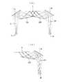
その様子を図11に示す。図中、131は表示装置本体部を示し、観察者の顔面の両眼の前方に保持されるよう支持部材が頭部を介して固定している。その支持部材としては、一端を表示装置本体部131に接合し、観察者のこめかみから耳の上部にかけて延在する左右の前フレーム132と、前フレーム132の他端に接合され、観察者の側頭部を渡るように延在する左右の後フレーム133と、左右の後フレーム133の他端に挟まれるように自らの両端を一方づつ接合し、観察者の頭頂部を支持する頭頂フレーム134とから構成されている。
また、前フレーム132における上記の後フレーム133との接合近傍には、弾性体からなり例えば金属板バネ等で構成されたリヤプレート135が接合されている。このリヤプレート135は、上記支持部材の一翼を担うリヤカバー136が観察者の後頭部から首のつけねにかかる部分で耳の後方に位置して支持可能となるように接合されている。リヤプレート135又はリヤカバー136内にの観察者の耳に対応する位置にスピーカー139が取り付けられている。
映像・音声信号等を外部から送信するためのケーブル141が表示装置本体部131から、頭頂フレーム134、後フレーム133、前フレーム132、リヤプレート135の内部を介してリヤプレート135あるいはリヤカバー136の後端部より外部に突出している。そして、このケーブル141はビデオ再生装置140に接続されている。なお、図中、140aはビデオ再生装置140のスイッチやボリュウム調整部である。
なお、ケーブル141は先端をジャックして、既存のビデオデッキ等に取り付け可能としてもよい。さらに、TV電波受信用チューナーに接続してTV鑑賞用としてもよいし、コンピュータに接続してコンピュータグラフィックスの映像や、コンピュータからのメッセージ映像等を受信するようにしてもよい。また、邪魔なコードを排斥するために、アンテナを接続して外部からの信号を電波によって受信するようにしても構わない。
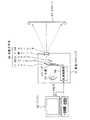
また、本発明の画像表示装置の観察光学系は、瞳1R、1L側から被写体からの光を導入し、画像表示素子3の位置に撮像素子を配することにより結像光学系として用いることも可能である。図12に本発明の観察光学系の左右の片側の光学系11と12(11Rと12R又は12Lと12L)のみを電子カメラ40の撮影部の撮影用対物光学系42に組み込んだ構成の概念図を示す。もちろん、本発明の観察光学系の左右の両方の光学系を用いてもよい(入射瞳が2個の光学系になる。)。この例の場合は、撮影用光路41上に配置された撮影用対物光学系42は、実施例1と同様の光学系を光路を逆にして用いており、瞳1(1R又は1L)の位置に絞り1’を配置している。この撮影用対物光学系42により形成された物体像は、ローパスフィルター、赤外カットフィルター等のフィルター44を介してCCD45の撮像面46上に形成される。このCCD45で受光された物体像は、処理手段51を介し、液晶表示素子(LCD)52上に電子像として表示される。また、この処理手段51は、CCD45で撮影された物体像を電子情報として記録する記録手段54の制御も行う。LCD52に表示された画像は、偏心プリズムからなる接眼光学系53を介して観察者眼球Eに導かれる。この接眼光学系53としては、他の偏心光学系を用いてもよい。なお、この撮影用対物光学系42は他のレンズ(正レンズ、負レンズ)をミラー11、12の物体側あるいは像側にその構成要素として含んでいてもよい。
このように構成されたカメラ40は、撮影用対物光学系42を少ない光学部材で構成でき、装置全体を小型化することができ、低価格で、他の部材を考慮してデットスペースの少ないカメラとすることができると共に、デザインの自由度が大きなものとなる。
なお、本例では、撮影用対物光学系42のカバー部材43はとして、平行平面板を配置しているが、パワーを持ったレンズを用いてもよい。
また、本発明の観察光学系の左右の片側のみの光学系は、画像表示素子3の位置に投影用の像面を配置し、瞳1の前方にスクリーンを配置することにより投影光学系としても用いることができる。もちろん、この場合も、本発明の観察光学系の左右の両方の光学系を用いてもよい(射出瞳が2個の光学系になる。)。図13に、パソコン90と液晶プロジェクタ91とを組み合わせたプレゼンテーションシステムの投影光学系96に本発明による偏心プリズム光学系を用いた構成の概念図を示す。この例の場合は、投影光学系96に実施例1と同様の光学系を用いている。同図において、パソコン90上で作成された画像・原稿データは、モニタ出力から分岐して液晶プロジェクタ91の処理制御部98に出力される。液晶プロジェクタ91の処理制御部98では、この入力されたデータが処理され、液晶パネル(LCP)93に出力される。液晶パネル93では、この入力画像データに応じた画像が表示される。そして、光源92からの光は、液晶パネル93に表示した画像の階調によってその透過量が決定された後、液晶パネル93直前に配置したフィールドレンズ95と本発明の光学系の2枚のミラー11、12と正レンズのカバーレンズ94とからなる投影光学系96を介してスクリーン97に投影される。
このように構成されたプロジェクタは、少ない光学部材で構成でき、低コスト化が実現できると共に、小型化が可能である。
以上の本発明の画像表示装置は、例えば次のように構成することができる。
〔1〕 観察画像を画像表示部に形成する画像表示素子と、前記画像表示素子が形成した画像を観察者眼球位置に相当する瞳に導く観察光学系とを含んだ画像表示装置において、
前記画像表示素子が、複数の画素を単板上に並設させた1枚の画像表示素子を有して構成され、
前記1枚の画像表示素子の少なくとも中央部分に位置する各画素が、観察者の左右の眼球に光束を導けるような射出角度で画像光束を放射するように構成され、
前記観察光学系が、観察者の左眼に光束を導く左側接眼部と、観察者の右眼に光束を導く右側接眼部とで構成され、
前記左側接眼部が、前記画像表示素子側から順に、左側第1反射面と、左側第2反射面を有し、前記2つの反射面が、反射ミラーでかつ偏心収差補正機能を有した回転非対称な曲面反射面にて構成され、
前記右側接眼部が、前記画像表示素子側から順に、右側第1反射面と、右側第2反射面を有し、前記2つの反射面が、反射ミラーでかつ偏心収差補正機能を有した回転非対称な曲面反射面にて構成され、
前記観察光学系は、観察者の両眼の中心を通る面を対称面とした左右対称な光路を形成できるように、前記反射面が左右対称に配置され、
前記左側第1反射面のX方向のパワーをP1x、Y方向のパワーをP1y、前記左側第2反射面のX方向のパワーをP2x、Y方向のパワーをP2yと定義したとき、以下の条件式を満足することを特徴とする画像表示装置。
P1x<0 ・・・(1)
P2x>0 ・・・(2)
ただし、X方向は前記接眼部の偏心方向と垂直な方向、
Y方向は前記接眼部の偏心方向、
である。
〔2〕 観察画像を画像表示部に形成する画像表示素子と、前記画像表示素子が形成した画像を観察者眼球位置に相当する瞳に導く観察光学系とを含んだ画像表示装置において、
前記画像表示素子が、複数の画素を単板上に並設させた1枚の画像表示素子を有して構成され、
前記1枚の画像表示素子の少なくとも中央部分に位置する各画素が、観察者の左右の眼球に光束を導けるような射出角度で画像光束を放射するように構成され、
前記観察光学系が、観察者の左眼に光束を導く左側接眼部と、観察者の右眼に光束を導く右側接眼部とで構成され、
前記左側接眼部が、前記画像表示素子側から順に、左側第1反射面と、左側第2反射面と、パワーの弱いレンズとを有し、前記2つの反射面が、反射ミラーでかつ偏心収差補正機能を有した回転非対称な曲面反射面にて構成され、
前記右側接眼部が、前記画像表示素子側から順に、右側第1反射面と、右側第2反射面と、パワーの弱いレンズとを有し、前記2つの反射面が、反射ミラーでかつ偏心収差補正機能を有した回転非対称な曲面反射面にて構成され、
前記観察光学系は、観察者の両眼の中心を通る面を対称面とした左右対称な光路を形成できるように、前記反射面が左右対称に配置され、
前記左側第1反射面のX方向のパワーをP1x、Y方向のパワーをP1y、前記左側第2反射面のX方向のパワーをP2x、Y方向のパワーをP2yと定義したとき、以下の条件式を満足することを特徴とする画像表示装置。
P1x<0 ・・・(1)
P2x>0 ・・・(2)
ただし、X方向は前記接眼部の偏心方向と垂直な方向、
Y方向は前記接眼部の偏心方向、
である。
〔3〕 上記1又は2において、
全ての前記反射面が対称面を1面のみ備えた自由曲面形状であることを特徴とする画像表示装置。
〔4〕 上記2又は3において、
前記パワーの弱いレンズの少なくとも1面が、偏心収差補正機能を有した回転非対称な曲面形状にて構成され、対称面を1面のみ備えた自由曲面形状であることを特徴とする画像表示装置。
〔5〕 上記1から4の何れか1項において、
以下の条件式を満足することを特徴とする画像表示装置。
−3.0<P1x/Px<−0.2 ・・・(3)
3.0>P2x/Px>0.3 ・・・(4)
ただし、Px、Pyは前記接眼部全系のX方向、Y方向のパワーである。
〔6〕 上記5において、
−2.0<P1x/Px<−0.4 ・・・(5)
2.0>P2x/Px>0.5 ・・・(6)
〔7〕 上記1から6の何れか1項において、
−0.5<P1y/Py<1.0 ・・・(7)
2.0>P2y/Py>0.3 ・・・(8)
〔8〕 上記7において、
−0.3<P1y/Py<0.8 ・・・(9)
1.3>P2y/Py>0.5 ・・・(10)
〔9〕 上記1から8の何れか1項において、
前記左側第1反射面と前記右側第1反射面との境界部分を含む領域に対して、前記画像表示素子の中心領域から垂直に放射された光線がゴースト光として反射しないように反射防止部材を設けたことを特徴とする画像表示装置。
〔10〕 上記1から9の何れか1項において、
前記画像表示素子と前記左側第1反射面及び前記右側第1反射面との間に、前記1枚の画像表示素子の少なくとも中央部分に位置する各画素から放射される所定の射出角度を持った画像光束の光強度を前記各画素面の垂直方向に放射される光束強度より強くするような振り分け光増強部材を配置したことを特徴とする画像表示装置。
〔11〕 上記1から10の何れか1項において、
前記画像表示素子の少なくとも中央部分に位置する各画素から観察者の眼球に導かれる左右の光束の軸上主光線間のなす角度をθとしたときに、以下の条件式を満足することを特徴とする画像表示装置。
20°<θ<150° ・・・(11)
〔12〕 上記1から11の何れか1項に記載の画像表示装置の前記画像表示素子に代えて撮像素子を配置し、前記瞳を被写体からの光束の通過する入射瞳として構成し、被写体の像を前記撮像素子上に形成することを特徴とする撮像装置。
〔13〕 上記1から11の何れか1項に記載の画像表示装置の前記画像表示素子に代えて投影物体を配置し、前記瞳の前方にスクリーンが配置して、前記投影物体の投影像を前記スクリーン上に形成することを特徴とする投影装置。
【発明の効果】
以上の説明から明らかに、本発明の画像表示装置においては、1枚の画像表示素子と、左右の接眼部をそれぞれ2枚の反射ミラーとで構成するか、左右の接眼部にパワーの弱いレンズが加わった構成であるので、画像表示素子が1枚で両眼視できるため、コストが非常に安くなる。また、部品点数が非常に少ないため、組み立てが簡単である。さらに、大きなプリズムを使用していないため、非常に軽量化できる。さらに、ハーフミラーを使用していないため、明るい画像が観察できる。
【図面の簡単な説明】
【図1】本発明の実施例1の画像表示装置の光学系の光学面と光路を示す水平断面図である。
【図2】本発明の実施例2の画像表示装置の図1と同様の水平断面図である。
【図3】本発明の実施例3の画像表示装置の図1と同様の水平断面図である。
【図4】本発明の実施例4の画像表示装置の図1と同様の水平断面図である。
【図5】本発明の実施例5の画像表示装置の図1と同様の水平断面図である。
【図6】実施例1の横収差図である。
【図7】実施例4の横収差図である。
【図8】本発明による接眼光学系の偏心方向と垂直な方向の主光線を示す模式図である。
【図9】偏心光学系及び偏心光学面のパワーの定義を説明するための図である。
【図10】本発明において使用可能な画像表示素子、そのための振り分け光増強部材、反射防止部材を説明するための図である。
【図11】本発明の画像表示装置を両眼に装着する構成にした場合の様子を示す図である。
【図12】本発明の光学系を電子カメラの撮影部の撮影用対物光学系に組み込んだ構成の概念図である。
【図13】本発明による光学系をプレゼンテーションシステムの投影光学系に用いた構成の概念図である。
【符号の説明】
E…観察者眼球
L1…第1反射面(凸レンズ)
L2…第2反射面(凹レンズ)
1、1L、1R…射出瞳
2L、2R…軸上主光線(光軸)
3…画像表示素子(像面)
11、11L、11R…第1ミラー
12、12L、12R…第2ミラー
20L、20R…補正レンズ
21L、21R…補正レンズの第1面
22L、22R…補正レンズの第2面
29…境界部分
31…液晶表示素子
32…白色バックライト
33…画像表示素子
34…画素
35…光束振り分けマイクロプリズム
36…反射防止部材
37…表示光束
40…電子カメラ
41…撮影用光路
42…撮影用対物光学系
43…カバー部材
44…フィルター
45…CCD
46…撮像面
51…処理手段
52…液晶表示素子(LCD)
53…接眼光学系
54…記録手段
90…パソコン
91…液晶プロジェクタ
92…光源
93…液晶パネル(LCP)
94…カバーレンズ
95…フィールドレンズ
96…投影光学系
97…スクリーン
98…処理制御部
131…表示装置本体部
132…前フレーム
133…後フレーム
134…頭頂フレーム
135…リヤプレート
136…リヤカバー
139…スピーカー
140…ビデオ再生装置
140a…ボリュウム調整部
141…ケーブルBACKGROUND OF THE INVENTION
The present invention relates to an image display device, and more particularly to a head- or face-mounted image display device that can be held on an observer's head or face.
[Prior art]
Conventionally, as an image display device for observing an image of one image display element with both eyes, JP-A-6-110013, JP-A-7-287185, JP-A-9-61748, JP-A-9-181998, Known as Kaihei 9-181999, Tokuhei Hei 10-504115, and the like.
[Problems to be solved by the invention]
Among them, the one disclosed in Japanese Patent Laid-Open No. 6-110013 has a two-mirror configuration, but various aberrations are corrected by a lens arranged in front of the pupil, which makes correction difficult and increases the size of the apparatus. Invite.
Japanese Patent Laid-Open No. 7-287185 uses a plurality of mirrors and performs an image forming operation with a single convex lens. Therefore, assembly adjustment is very difficult, and appropriate performance cannot be achieved. In addition, although the image display elements are arranged three-dimensionally, the left and right images are rotated in reverse because they are symmetrical optical systems.
In Japanese Patent Laid-Open No. 9-61748, display light of an LCD (liquid crystal display element) is divided using a half mirror and observed with both eyes. Therefore, since the display light is divided into the left and right eyeballs, the observation image is weak and dark.
In addition, JP-A-9-181998 and JP-A-9-181999 are heavy because the observation optical system is composed of a large prism.
Moreover, in the table of JP 10-504115, the number of parts is very large, and the assembly is very complicated. In this case, since the half mirror is used, the observation image becomes weak and dark.
Japanese Patent Application Laid-Open No. 8-240773 does not have a single-plate binocular view for observing an image of one image display element with both eyes, but has a two-mirror configuration. Since this image display device cannot be viewed with both eyes unless there are two image display elements, a very inexpensive binocular image display device cannot be provided.
Furthermore, since recent image display devices are desired to be very small and light, an observation optical system that is light even at a few grams is desired.
The present invention has been made in view of such problems of the prior art, and its purpose is to guide an image from one image display element to both eyes without using a half mirror, and to observe brightly. By using a mirror with a rotationally asymmetric free-form surface without using a prism in the optical system, it is possible to provide an image display device such as a head-mounted image display device that has a small number of parts and is reduced in size and weight. is there.
[Means for Solving the Problems]
An image display device of the present invention that achieves the above object includes an image display element that forms an observation image on an image display unit, and an observation optical system that guides the image formed by the image display element to a pupil corresponding to the position of the eyeball of the observer. In an image display device including
The image display element has a single image display element in which a plurality of pixels are arranged side by side on a single plate,
Each pixel located in at least the central portion of the one image display element is configured to emit an image light beam at an emission angle that can guide the light beam to the left and right eyeballs of an observer,
The observation optical system includes a left eyepiece that guides a light beam to the left eye of the observer and a right eyepiece that guides the light beam to the right eye of the observer,
The left eyepiece has a left first reflecting surface and a left second reflecting surface in order from the image display element side, and the two reflecting surfaces are reflecting mirrors and have a decentration aberration correcting function. Consists of an asymmetric curved reflecting surface,
The right eyepiece has a right first reflecting surface and a right second reflecting surface in order from the image display element side, and the two reflecting surfaces are reflecting mirrors and have a decentration aberration correcting function. Consists of an asymmetric curved reflecting surface,
In the observation optical system, the reflection surfaces are arranged symmetrically so as to form a bilaterally symmetric optical path with a plane passing through the center of both eyes of the observer as a symmetry plane,
When the power in the X direction of the left first reflecting surface is defined as P1x, the power in the Y direction is defined as P1y, the power in the X direction of the left second reflecting surface is defined as P2x, and the power in the Y direction is defined as P2y, the following conditional expression It is characterized by satisfying.
P1x <0 (1)
P2x> 0 (2)
However, the X direction is a direction perpendicular to the eccentric direction of the eyepiece,
Y direction is the eccentric direction of the eyepiece,
It is.
Another image display device of the present invention includes an image display element that forms an observation image on an image display unit, and an observation optical system that guides the image formed by the image display element to a pupil corresponding to the position of the observer's eyeball. In the image display device,
The image display element has a single image display element in which a plurality of pixels are arranged side by side on a single plate,
Each pixel located in at least the central portion of the one image display element is configured to emit an image light beam at an emission angle that can guide the light beam to the left and right eyeballs of an observer,
The observation optical system includes a left eyepiece that guides a light beam to the left eye of the observer and a right eyepiece that guides the light beam to the right eye of the observer,
The left eyepiece has, in order from the image display element side, a left first reflecting surface, a left second reflecting surface, and a lens with weak power, and the two reflecting surfaces are reflecting mirrors and are eccentric. Consists of a rotationally asymmetric curved reflecting surface with an aberration correction function,
The right eyepiece has, in order from the image display element side, a right first reflecting surface, a right second reflecting surface, and a lens with weak power, and the two reflecting surfaces are reflecting mirrors and are eccentric. Consists of a rotationally asymmetric curved reflecting surface with an aberration correction function,
In the observation optical system, the reflection surfaces are arranged symmetrically so as to form a bilaterally symmetric optical path with a plane passing through the center of both eyes of the observer as a symmetry plane,
When the power in the X direction of the left first reflecting surface is defined as P1x, the power in the Y direction is defined as P1y, the power in the X direction of the left second reflecting surface is defined as P2x, and the power in the Y direction is defined as P2y, the following conditional expression It is characterized by satisfying.
P1x <0 (1)
P2x> 0 (2)
However, the X direction is a direction perpendicular to the eccentric direction of the eyepiece,
Y direction is the eccentric direction of the eyepiece,
It is.
Hereinafter, the reason and effect | action which take the said structure in this invention are demonstrated.
The image display apparatus according to the present invention is configured such that one image display element and the left and right eyepieces are each composed of two reflecting mirrors, or a lens with low power is added to the left and right eyepieces. . Therefore, since one image display element can be viewed with both eyes, the cost is very low. Moreover, since the number of parts is very small, assembly is easy. Furthermore, since a large prism is not used, the weight can be greatly reduced. Furthermore, since a half mirror is not used, a bright image can be observed.
Here, the left and right eyepieces are each composed of two reflection mirrors, and an eccentric arrangement is required to form an eyepiece optical system with the two reflection mirrors. Therefore, the two reflecting mirrors are composed of a rotationally asymmetric curved reflecting surface having a decentration aberration correcting function, and good aberration correction can be performed.
Here, as a surface of a rotationally asymmetric curved surface shape, a free-form surface is typically used in the present invention. The free-form surface is defined by the following equation. The Z axis of this defining formula is the axis of the free-form surface.
In the spherical term,
c: vertex curvature
k: Conic constant (conical constant)
r = √ (X2 + Y2 )
It is.
The free-form surface term is
In general, the free-form surface does not have a symmetric surface in both the XZ plane and the YZ plane, but by setting all odd-order terms of X to 0, the plane of symmetry is parallel to the YZ plane. Is a free-form surface with only one. Further, by setting all odd-numbered terms of Y to 0, a free-form surface having only one symmetry plane parallel to the XZ plane is obtained.
Further, another defining formula of the free-form surface which is a surface of the rotationally asymmetric curved surface can be defined by a Zernike polynomial. The shape of this surface is defined by the following formula (b). The Z axis of the defining formula (b) is the axis of the Zernike polynomial. The definition of the rotationally asymmetric surface is defined by polar coordinates of the height of the Z axis with respect to the XY plane, R is the distance from the Z axis in the XY plane, A is the azimuth around the Z axis, and the X axis It is expressed by the rotation angle measured from.
The above definition formula is shown for illustration of a rotationally asymmetric curved surface, and it goes without saying that the same effect can be obtained for any other definition formula.
In addition, the following definition formula (c) is mention | raise | lifted as an example of the other definition formula of a free-form surface.
Z = ΣΣCnm XY
As an example, when k = 7 (seventh order term) is considered, when expanded, it can be expressed by the following expression.
In the present invention, the following conditional expressions (1) and (2) are satisfied.
P1x <0 (1)
P2x> 0 (2)
However, the X direction is a direction perpendicular to the eccentric direction of the eyepiece,
Y direction is the eccentric direction of the eyepiece,
Conditional expressions (1) and (2) above define the focal length in the direction perpendicular to the eccentric direction of the axial principal ray, and the axial principal ray incident on the image display element is incident substantially perpendicularly. This is a conditional expression.
An image display device, particularly a liquid crystal display device (LCD), when viewed from an oblique direction, lowers resolution and contrast. In recent years, a technique for suppressing a decrease in contrast to some extent using a viewing angle widening film has been developed. However, in the case of a single-plate binocular optical system, images must be assigned to the left and right eyes, and the incident angle becomes large with respect to the eccentric direction of the axial principal ray. In order to suppress a reduction in contrast as much as possible, it is preferable to make the light incident substantially perpendicular to at least the X direction perpendicular to the eccentric direction.
FIG. 8 shows a schematic diagram of chief rays for achieving such a problem. This figure is a view in a direction perpendicular to the decentering direction, and is expressed as a coaxial optical system. The second reflecting surface (reflecting mirror) is represented by a convex lens L1, and the first reflecting surface (reflecting mirror) is represented by a concave lens L2. is there. When the ray E is traced back from the pupil E, the off-axis chief ray becomes divergent light from the first convex lens L1 and converges with the concave lens L2, as is apparent from FIG. Will come out as. Therefore, by satisfying the conditional expressions (1) and (2), it is possible to make the image display element substantially perpendicularly incident in a direction perpendicular to the eccentric direction. In addition, with the above configuration, the optical system can be shortened even when the focal length is long, and in fact, a very thin optical system is possible because it is folded using a mirror instead of the lenses L1 and L2. It becomes.
Here, the definition of the power of the decentered optical system and the decentered optical surface will be described. As shown in FIG. 9, when the decentering direction of the decentered optical system is taken in the Y-axis direction, a minute height d (for example, 1 mm or 0) in the YZ plane parallel to the axial principal ray of the decentered optical system. .1 mm) is incident from the object side, and the angle formed by projecting the light beam emitted from the decentered optical system and the axial principal ray on the YZ plane is NA′yi, and NA′yi / d is Y The optical power Py of the decentering optical system in the direction, a light beam having a minute height d in the X direction parallel to the axial principal ray of the decentering optical system and perpendicular to the YZ plane is incident from the object side, and the imaging optical system NA′xi is defined as an angle formed when the light beam emitted from the plane and the axial principal ray are orthogonal to the YZ plane and projected onto the surface including the axial principal ray, and NA′xi / d is defined as the X direction. The power Px of the entire image forming optical system. Similarly, the power Pny in the Y direction and the power Pnx in the X direction of the optical surface n are determined.
By the way, in the observation optical system of the present invention, the two right and left reflecting surfaces are symmetrically shaped so that a symmetrical optical path with a plane passing through the center of both eyes of the observer can be formed. Decided and placed. In that case, the eccentric directions of the left and right eyepieces do not necessarily have to be the same direction, but the left and right eyepieces have the same horizontal direction (Y-axis direction) as in the examples described later. Is desirable.
In the configuration as described above, all the reflecting surfaces can be formed into a free-form surface shape having only one symmetry plane.
Further, at least one surface of the lens having a weak power is configured by a rotationally asymmetric curved surface shape having a decentration aberration correcting function, and can be a free curved surface shape having only one symmetric surface.
Furthermore, decentration aberrations can be satisfactorily corrected by making both surfaces of the lens having weak power into a free-form surface having a rotationally asymmetric curved surface shape and having only one symmetric surface (Examples 4 and 5).
Furthermore, it is desirable that conditional expressions (1) and (2) satisfy the following conditional expressions.
−3.0 <P1x / Px <−0.2 (3)
3.0> P2x / Px> 0.3 (4)
However, Px and Py are powers in the X direction and Y direction of the entire system of the eyepiece.
If the above conditional expression is satisfied, the telecentricity in the X direction can be further ensured, and the reduction in contrast of the display image can be suppressed.
Furthermore, it is desirable to satisfy the following conditional expression.
−2.0 <P1x / Px <−0.4 (5)
2.0> P2x / Px> 0.5 (6)
It is desirable that conditional expressions (7) and (8) are satisfied.
-0.5 <P1y / Py <1.0 (7)
2.0> P2y / Py> 0.3 (8)
The above conditional expression is a conditional expression that prescribes the power of the axial principal ray in the decentering direction (Y direction). By appropriately allocating the power distribution of the mirrors of the first reflecting surface and the second reflecting surface, the decentration aberration in the Y direction. Is a condition for correcting the image quality well. Exceeding the upper limit of 1.0 to conditional expression (7) is not preferable because the decentration aberration generated on the first reflecting surface becomes large. If the lower limit of -0.5 of the conditional expression (7) is exceeded, the off-axis chief ray diverged by the back ray tracing further increases the angle, and the effective diameter of the second reflecting surface has to be increased. Invite.
If the upper limit of 2.0 of conditional expression (8) is exceeded, the power of the second reflecting surface becomes too large, and as a result, the power of the first reflecting surface must be weakened. As a result, the imaging positions in the X direction and the Y direction are greatly different, which is not preferable. If the lower limit of 0.3 of conditional expression (8) is exceeded, the power of the first reflecting surface must be increased, and decentration aberrations cannot be corrected. Therefore, within the range of the conditional expressions (7) and (8), it is possible to reduce the difference from the X direction while satisfactorily correcting the decentration aberration in the Y direction.
Further, the following conditional expression is desirable.
-0.3 <P1y / Py <0.8 (9)
1.3> P2y / Py> 0.5 (10)
In addition, an antireflection member is provided so that a light beam emitted perpendicularly from the central region of the image display element is not reflected as ghost light with respect to a region including a boundary portion between the left first reflective surface and the right first reflective surface. It is desirable.
In addition, an image having a predetermined emission angle emitted from each pixel located at least in the central portion of the one image display element between the image display element and the left first reflection surface and the right first reflection surface. It is desirable to arrange a sorting light enhancing member that makes the light intensity of the light beam stronger than the light beam intensity emitted in the vertical direction of each pixel surface.
Further, when the angle formed between the axial principal rays of the right and left light beams guided from each pixel located at least in the central portion of the image display element to the observer's eyeball is θ, the following conditional expression may be satisfied: desirable.
20 ° <θ <150 ° (11)
This conditional expression is a conditional expression for appropriately separating the image luminous flux for both eyes. When the lower limit of 20 ° is exceeded, the left and right optical surfaces, particularly the left and right optical elements arranged at positions closest to the image display element are used. The effective diameters of the first reflecting surfaces overlap, and the optical system must be enlarged in order to ensure the effective diameter, which is not suitable for the optical system of the head or face-mounted image display device. End up. On the other hand, if the upper limit of 150 ° is exceeded, an image display element having a very wide viewing angle characteristic is required, and at the same time, the solid angle of the image light beam becomes small, and as a result, a bright image cannot be observed. More preferably, the angle θ satisfies the following conditional expression.
30 ° <θ <120 ° (12)
In addition, the image display device as described above has an imaging element instead of the image display element, and the pupil is configured as an entrance pupil through which a light beam from the subject passes, and an image of the subject is formed on the imaging element. It can also be used as a device.
Furthermore, it can also be used as a projection apparatus in which a projection object is arranged instead of the image display element, and a screen is arranged in front of the pupil to form a projection image of the projection object on the screen.
DETAILED DESCRIPTION OF THE INVENTION
Hereinafter, an image display device of the present invention will be described based on examples.
In the following examples, coordinates are set such that the observer's visual axis direction (front direction) is the Z axis, the horizontal direction is the Y axis, and the vertical direction is the X axis.
In the numerical data of each example to be described later, an eyepiece optical system for the right eye is shown, and is shown by back ray tracing data from the
FIG. 1 is a horizontal (YZ plane) cross-sectional view showing an optical surface and an optical path of an optical system of the image display apparatus according to the first embodiment. In the figure, (a) shows the optical path for both eyes, and (b) shows the optical path for right eye. In order to distinguish between the optical surfaces in the left and right optical paths, the axial principal ray, and the pupil, “L” and “R” are given after the reference numerals. Further, in order to be consistent with the description of the numerical data described later, the order in which the signs are taken is based on back ray tracing. The same applies to other embodiments.
When the observation optical system of this embodiment is configured as a head-mounted image display device, an axial principal ray (optical axis) 2R for tracing back rays from the
However, “L” is added instead of “R” after the code. In the following description, “R” and “L” after the reference are omitted unless otherwise required.
In this embodiment, since only two mirrors 11R (L) and 12R (L) are used, the cost and the weight can be reduced. When a prism is used in the observation optical system, chromatic aberration is generated at the entrance surface and the exit surface. However, since only two mirrors 11R (L) and 12R (L) are used, no chromatic aberration is generated.
2 and 3 are sectional views similar to FIG. 1 of the image display devices according to the second and third embodiments, respectively. Since the second and third embodiments are the same as the first embodiment in FIG.
FIG. 4 is a cross-sectional view similar to FIG. 1 of the image display apparatus according to the fourth embodiment. When the observation optical system of this embodiment is configured as a head-mounted image display device, an axial principal ray (optical axis) 2R for tracing back rays from the
In this embodiment, the decentering aberration can be corrected very well by combining the two mirrors 11R (L) and 12R (L) and the
FIG. 5 is a cross-sectional view similar to FIG. 1 of the image display apparatus according to the fifth embodiment. The fifth embodiment is the same as the fourth embodiment shown in FIG.
Next, the configuration parameters of Examples 1 to 5 are shown. These structural parameters are described only for the optical system for the right eye. For the optical system for the left eye, the plane passing through the center of the straight line connecting the centers of the left and
For the eccentric surface, the amount of eccentricity from the center of the origin of the optical system to the top position of the surface (X, Y, and Z directions are X, Y, and Z, respectively) and the center axis of the surface (free With respect to the curved surface, inclination angles (α, β, γ (°), respectively) about the X axis, the Y axis, and the Z axis of the equation (a) are given. In this case, positive α and β mean counterclockwise rotation with respect to the positive direction of each axis, and positive γ means clockwise rotation with respect to the positive direction of the Z axis. Note that the α, β, and γ rotations of the central axis of the surface are performed by first rotating the central axis of the surface and its XYZ orthogonal coordinate system by α counterclockwise around the X axis, and then rotating the rotation. The center axis of the surface is rotated β counterclockwise around the Y axis of the new coordinate system, and the coordinate system rotated once is also rotated β counterclockwise around the Y axis and then rotated twice. The center axis of the surface is rotated γ clockwise around the Z axis of the new coordinate system.
In addition, among the optical action surfaces constituting the optical system of each embodiment, when a specific surface and a subsequent surface constitute a coaxial optical system, a surface interval is given, and in addition, the refractive index of the medium, Abbe numbers are given according to idioms.
Further, the shape of the surface of the free curved surface used in the present invention is defined by the equation (a), and the Z axis of the defining equation becomes the axis of the free curved surface.
In addition, the term regarding the free-form surface for which no data is described is zero. The refractive index is shown for d-line (wavelength 587.56 nm). The unit of length is mm.
In the following examples, when the observation optical system is used, the observation field angles of Examples 1 to 5 are a horizontal half field angle of 7.5 ° and a vertical half field angle of 5.6 °. In Examples 1 and 4, the size of the image display element is 14.2 × 10.7 mm. In Examples 2 and 5, the size of the image display element is 11.2 × 8.4 mm. In No. 3, the size of the image display element is 8.9 × 6.7 mm, and in all the examples, the pupil diameter is 4 mm.
In the following configuration parameter tables, “FFS” indicates a free-form surface, and “RE” indicates a reflective surface.
The values relating to the conditional expressions (1) to (11) of Examples 1 to 5 are shown in the following table.
Further, when the
By the way, when the display light beam emitted from the
Now, by supporting the observation optical system as described above, it can be configured as a binocular wearing image display device, and can be configured as a stationary or portable image display device that can be observed with both eyes. Can do.
This is shown in FIG. In the figure,
Also, a
A
The
In addition, the observation optical system of the image display apparatus of the present invention can be used as an imaging optical system by introducing light from a subject from the
The camera 40 configured as described above can configure the photographing objective optical system 42 with a small number of optical members, can reduce the size of the entire apparatus, is inexpensive, and has a small dead space in consideration of other members. And the degree of freedom in design is large.
In this example, a plane-parallel plate is disposed as the
Further, the optical system of only one of the left and right sides of the observation optical system of the present invention can be used as a projection optical system by disposing an image plane for projection at the position of the
The projector configured as described above can be configured with a small number of optical members, can realize cost reduction, and can be downsized.
The above-described image display device of the present invention can be configured as follows, for example.
[1] In an image display device including an image display element that forms an observation image on an image display unit, and an observation optical system that guides an image formed by the image display element to a pupil corresponding to an observer's eyeball position.
The image display element has a single image display element in which a plurality of pixels are arranged side by side on a single plate,
Each pixel located in at least the central portion of the one image display element is configured to emit an image light beam at an emission angle that can guide the light beam to the left and right eyeballs of an observer,
The observation optical system includes a left eyepiece that guides a light beam to the left eye of the observer and a right eyepiece that guides the light beam to the right eye of the observer,
The left eyepiece has a left first reflecting surface and a left second reflecting surface in order from the image display element side, and the two reflecting surfaces are reflecting mirrors and have a decentration aberration correcting function. Consists of an asymmetric curved reflecting surface,
The right eyepiece has a right first reflecting surface and a right second reflecting surface in order from the image display element side, and the two reflecting surfaces are reflecting mirrors and have a decentration aberration correcting function. Consists of an asymmetric curved reflecting surface,
In the observation optical system, the reflection surfaces are arranged symmetrically so as to form a bilaterally symmetric optical path with a plane passing through the center of both eyes of the observer as a symmetry plane,
When the power in the X direction of the left first reflecting surface is defined as P1x, the power in the Y direction is defined as P1y, the power in the X direction of the left second reflecting surface is defined as P2x, and the power in the Y direction is defined as P2y, the following conditional expression An image display device characterized by satisfying
P1x <0 (1)
P2x> 0 (2)
However, the X direction is a direction perpendicular to the eccentric direction of the eyepiece,
Y direction is the eccentric direction of the eyepiece,
It is.
[2] In an image display device including an image display element that forms an observation image on an image display unit, and an observation optical system that guides an image formed by the image display element to a pupil corresponding to an observer eyeball position.
The image display element has a single image display element in which a plurality of pixels are arranged side by side on a single plate,
Each pixel located in at least the central portion of the one image display element is configured to emit an image light beam at an emission angle that can guide the light beam to the left and right eyeballs of an observer,
The observation optical system includes a left eyepiece that guides a light beam to the left eye of the observer and a right eyepiece that guides the light beam to the right eye of the observer,
The left eyepiece has, in order from the image display element side, a left first reflecting surface, a left second reflecting surface, and a lens with weak power, and the two reflecting surfaces are reflecting mirrors and are eccentric. Consists of a rotationally asymmetric curved reflecting surface with an aberration correction function,
The right eyepiece has, in order from the image display element side, a right first reflecting surface, a right second reflecting surface, and a lens with weak power, and the two reflecting surfaces are reflecting mirrors and are eccentric. Consists of a rotationally asymmetric curved reflecting surface with an aberration correction function,
In the observation optical system, the reflection surfaces are arranged symmetrically so as to form a bilaterally symmetric optical path with a plane passing through the center of both eyes of the observer as a symmetry plane,
When the power in the X direction of the left first reflecting surface is defined as P1x, the power in the Y direction is defined as P1y, the power in the X direction of the left second reflecting surface is defined as P2x, and the power in the Y direction is defined as P2y, the following conditional expression An image display device characterized by satisfying
P1x <0 (1)
P2x> 0 (2)
However, the X direction is a direction perpendicular to the eccentric direction of the eyepiece,
Y direction is the eccentric direction of the eyepiece,
It is.
[3] In the above 1 or 2,
An image display device characterized in that all the reflection surfaces have a free-form surface shape having only one symmetry surface.
[4] In the above 2 or 3,
An image display device, wherein at least one surface of the weak lens has a rotationally asymmetric curved surface shape having a decentration aberration correcting function, and has a free curved surface shape having only one symmetric surface.
[5] In any one of the
An image display device satisfying the following conditional expression:
−3.0 <P1x / Px <−0.2 (3)
3.0> P2x / Px> 0.3 (4)
However, Px and Py are powers in the X direction and Y direction of the entire system of the eyepiece.
[6] In the above item 5,
−2.0 <P1x / Px <−0.4 (5)
2.0> P2x / Px> 0.5 (6)
[7] In any one of the
-0.5 <P1y / Py <1.0 (7)
2.0> P2y / Py> 0.3 (8)
[8] In the above item 7,
-0.3 <P1y / Py <0.8 (9)
1.3> P2y / Py> 0.5 (10)
[9] In any one of the
An antireflection member is provided so that a light beam emitted perpendicularly from a central region of the image display element is not reflected as ghost light with respect to a region including a boundary portion between the left first reflective surface and the right first reflective surface. An image display device provided.
[10] In any one of the
Between the image display element and the left first reflective surface and the right first reflective surface, a predetermined emission angle radiated from each pixel located at least in the central portion of the one image display element is provided. An image display device comprising: a sorting light enhancing member arranged such that a light intensity of an image light beam is higher than a light beam intensity emitted in a direction perpendicular to each pixel surface.
[11] In any one of 1 to 10 above,
The following conditional expression is satisfied, where θ is an angle formed between the axial principal rays of the right and left light beams guided to the observer's eyeball from each pixel located at least in the central portion of the image display element: An image display device.
20 ° <θ <150 ° (11)
[12] An imaging device is arranged instead of the image display device of the image display device according to any one of 1 to 11, and the pupil is configured as an entrance pupil through which a light beam from the subject passes. An imaging apparatus, wherein an image is formed on the imaging element.
[13] A projection object is disposed instead of the image display element of the image display device according to any one of 1 to 11, and a screen is disposed in front of the pupil, and a projection image of the projection object is obtained. A projection device formed on the screen.
【The invention's effect】
As is apparent from the above description, in the image display device of the present invention, one image display element and the left and right eyepieces are each composed of two reflecting mirrors, or the left and right eyepieces have power. Since a weak lens is added, the image display element can be viewed with both eyes with one sheet, and the cost is very low. Moreover, since the number of parts is very small, assembly is easy. Furthermore, since a large prism is not used, the weight can be greatly reduced. Furthermore, since a half mirror is not used, a bright image can be observed.
[Brief description of the drawings]
FIG. 1 is a horizontal sectional view showing an optical surface and an optical path of an optical system of an image display apparatus according to
FIG. 2 is a horizontal sectional view similar to FIG. 1 of an image display device according to a second embodiment of the present invention.
FIG. 3 is a horizontal sectional view similar to FIG. 1 of an image display apparatus according to a third embodiment of the present invention.
FIG. 4 is a horizontal sectional view similar to FIG. 1 of an image display apparatus according to a fourth embodiment of the present invention.
FIG. 5 is a horizontal sectional view similar to FIG. 1 of an image display apparatus according to Embodiment 5 of the present invention.
6 is a lateral aberration diagram of Example 1. FIG.
7 is a lateral aberration diagram of Example 4. FIG.
FIG. 8 is a schematic diagram showing chief rays in a direction perpendicular to the decentering direction of the eyepiece optical system according to the present invention.
FIG. 9 is a diagram for explaining the definition of power of a decentered optical system and a decentered optical surface.
FIG. 10 is a diagram for explaining an image display element that can be used in the present invention, a sorting light enhancing member, and an antireflection member therefor.
FIG. 11 is a diagram showing a state in which the image display device of the present invention is configured to be worn on both eyes.
FIG. 12 is a conceptual diagram of a configuration in which the optical system of the present invention is incorporated into a photographing objective optical system of a photographing unit of an electronic camera.
FIG. 13 is a conceptual diagram of a configuration in which an optical system according to the present invention is used in a projection optical system of a presentation system.
[Explanation of symbols]
E ... Observer eyeball
L1 ... 1st reflective surface (convex lens)
L2 ... Second reflecting surface (concave lens)
1, 1L, 1R ... exit pupil
2L, 2R ... On-axis chief ray (optical axis)
3. Image display element (image plane)
11, 11L, 11R ... 1st mirror
12, 12L, 12R ... second mirror
20L, 20R ... Correction lens
21L, 21R: First surface of the correction lens
22L, 22R: Second surface of the correction lens
29 ... Boundary part
31 ... Liquid crystal display element
32 ... White backlight
33. Image display element
34 ... Pixels
35 ... Light beam distribution microprism
36 ... Antireflection member
37 ... Display light flux
40 ... Electronic camera
41. Optical path for photographing
42 ... Objective optical system for photographing
43 ... Cover member
44 ... Filter
45 ... CCD
46: Imaging surface
51. Processing means
52 ... Liquid crystal display (LCD)
53 ... Eyepiece optical system
54. Recording means
90 ... PC
91 ... Liquid crystal projector
92 ... Light source
93 ... Liquid crystal panel (LCP)
94: Cover lens
95 ... Field lens
96 ... projection optical system
97 ... Screen
98 ... Processing control unit
131 ... Display device main body
132 ... Previous frame
133 ... rear frame
134 ... Parietal frame
135 ... Rear plate
136 ... Rear cover
139 ... Speaker
140 ... Video playback device
140a ... Volume adjuster
141 ... cable
Claims (3)
Translated fromJapanese前記画像表示素子が、複数の画素を単板上に並設させた1枚の画像表示素子を有して構成され、
前記1枚の画像表示素子の少なくとも中央部分に位置する各画素が、観察者の左右の眼球に光束を導けるような射出角度で画像光束を放射するように構成され、
前記観察光学系が、観察者の左眼に光束を導く左側接眼部と、観察者の右眼に光束を導く右側接眼部とで構成され、
前記左側接眼部が、前記画像表示素子側から順に、左側第1反射面と、左側第2反射面を有し、前記2つの反射面が、反射ミラーでかつ偏心収差補正機能を有した回転非対称な曲面反射面にて構成され、
前記右側接眼部が、前記画像表示素子側から順に、右側第1反射面と、右側第2反射面を有し、前記2つの反射面が、反射ミラーでかつ偏心収差補正機能を有した回転非対称な曲面反射面にて構成され、
前記観察光学系は、観察者の両眼の中心を通る面を対称面とした左右対称な光路を形成できるように、前記反射面が左右対称に配置され、
前記左側第1反射面のX方向のパワーをP1x、Y方向のパワーをP1y、前記左側第2反射面のX方向のパワーをP2x、Y方向のパワーをP2yと定義したとき、以下の条件式を満足することを特徴とする画像表示装置。
P1x<0 ・・・(1)
P2x>0 ・・・(2)
ただし、X方向は前記接眼部の偏心方向と垂直な方向、
Y方向は前記接眼部の偏心方向、
である。In an image display device including an image display element that forms an observation image on an image display unit, and an observation optical system that guides an image formed by the image display element to a pupil corresponding to the position of the eyeball of the observer,
The image display element has a single image display element in which a plurality of pixels are arranged side by side on a single plate,
Each pixel located in at least the central portion of the one image display element is configured to emit an image light beam at an emission angle that can guide the light beam to the left and right eyeballs of an observer,
The observation optical system includes a left eyepiece that guides a light beam to the left eye of the observer and a right eyepiece that guides the light beam to the right eye of the observer,
The left eyepiece has a left first reflecting surface and a left second reflecting surface in order from the image display element side, and the two reflecting surfaces are reflecting mirrors and have a decentration aberration correcting function. Consists of an asymmetric curved reflecting surface,
The right eyepiece has a right first reflecting surface and a right second reflecting surface in order from the image display element side, and the two reflecting surfaces are reflecting mirrors and have a decentration aberration correcting function. Consists of an asymmetric curved reflecting surface,
In the observation optical system, the reflection surfaces are arranged symmetrically so as to form a bilaterally symmetric optical path with a plane passing through the center of both eyes of the observer as a symmetry plane,
When the power in the X direction of the left first reflecting surface is defined as P1x, the power in the Y direction is defined as P1y, the power in the X direction of the left second reflecting surface is defined as P2x, and the power in the Y direction is defined as P2y, the following conditional expression An image display device characterized by satisfying
P1x <0 (1)
P2x> 0 (2)
However, the X direction is a direction perpendicular to the eccentric direction of the eyepiece,
Y direction is the eccentric direction of the eyepiece,
It is.
前記画像表示素子が、複数の画素を単板上に並設させた1枚の画像表示素子を有して構成され、
前記1枚の画像表示素子の少なくとも中央部分に位置する各画素が、観察者の左右の眼球に光束を導けるような射出角度で画像光束を放射するように構成され、
前記観察光学系が、観察者の左眼に光束を導く左側接眼部と、観察者の右眼に光束を導く右側接眼部とで構成され、
前記左側接眼部が、前記画像表示素子側から順に、左側第1反射面と、左側第2反射面と、パワーの弱いレンズとを有し、前記2つの反射面が、反射ミラーでかつ偏心収差補正機能を有した回転非対称な曲面反射面にて構成され、
前記右側接眼部が、前記画像表示素子側から順に、右側第1反射面と、右側第2反射面と、パワーの弱いレンズとを有し、前記2つの反射面が、反射ミラーでかつ偏心収差補正機能を有した回転非対称な曲面反射面にて構成され、
前記観察光学系は、観察者の両眼の中心を通る面を対称面とした左右対称な光路を形成できるように、前記反射面が左右対称に配置され、
前記左側第1反射面のX方向のパワーをP1x、Y方向のパワーをP1y、前記左側第2反射面のX方向のパワーをP2x、Y方向のパワーをP2yと定義したとき、以下の条件式を満足することを特徴とする画像表示装置。
P1x<0 ・・・(1)
P2x>0 ・・・(2)
ただし、X方向は前記接眼部の偏心方向と垂直な方向、
Y方向は前記接眼部の偏心方向、
である。In an image display device including an image display element that forms an observation image on an image display unit, and an observation optical system that guides an image formed by the image display element to a pupil corresponding to the position of the eyeball of the observer,
The image display element has a single image display element in which a plurality of pixels are arranged side by side on a single plate,
Each pixel located in at least the central portion of the one image display element is configured to emit an image light beam at an emission angle that can guide the light beam to the left and right eyeballs of an observer,
The observation optical system includes a left eyepiece that guides a light beam to the left eye of the observer and a right eyepiece that guides the light beam to the right eye of the observer,
The left eyepiece has, in order from the image display element side, a left first reflecting surface, a left second reflecting surface, and a lens with weak power, and the two reflecting surfaces are reflecting mirrors and are eccentric. Consists of a rotationally asymmetric curved reflecting surface with an aberration correction function,
The right eyepiece has, in order from the image display element side, a right first reflecting surface, a right second reflecting surface, and a lens with weak power, and the two reflecting surfaces are reflecting mirrors and are eccentric. Consists of a rotationally asymmetric curved reflecting surface with an aberration correction function,
In the observation optical system, the reflection surfaces are arranged symmetrically so as to form a bilaterally symmetric optical path with a plane passing through the center of both eyes of the observer as a symmetry plane,
When the power in the X direction of the left first reflecting surface is defined as P1x, the power in the Y direction is defined as P1y, the power in the X direction of the left second reflecting surface is defined as P2x, and the power in the Y direction is defined as P2y, the following conditional expression An image display device characterized by satisfying
P1x <0 (1)
P2x> 0 (2)
However, the X direction is a direction perpendicular to the eccentric direction of the eyepiece,
Y direction is the eccentric direction of the eyepiece,
It is.
全ての前記反射面が対称面を1面のみ備えた自由曲面形状であることを特徴とする画像表示装置。In claim 1 or 2,
An image display device characterized in that all the reflection surfaces have a free-form surface shape having only one symmetry surface.
Priority Applications (1)
| Application Number | Priority Date | Filing Date | Title |
|---|---|---|---|
| JP2000306014AJP4579396B2 (en) | 2000-10-05 | 2000-10-05 | Image display device |
Applications Claiming Priority (1)
| Application Number | Priority Date | Filing Date | Title |
|---|---|---|---|
| JP2000306014AJP4579396B2 (en) | 2000-10-05 | 2000-10-05 | Image display device |
Publications (2)
| Publication Number | Publication Date |
|---|---|
| JP2002116405A JP2002116405A (en) | 2002-04-19 |
| JP4579396B2true JP4579396B2 (en) | 2010-11-10 |
Family
ID=18786774
Family Applications (1)
| Application Number | Title | Priority Date | Filing Date |
|---|---|---|---|
| JP2000306014AExpired - Fee RelatedJP4579396B2 (en) | 2000-10-05 | 2000-10-05 | Image display device |
Country Status (1)
| Country | Link |
|---|---|
| JP (1) | JP4579396B2 (en) |
Families Citing this family (4)
| Publication number | Priority date | Publication date | Assignee | Title |
|---|---|---|---|---|
| KR100716829B1 (en)* | 2005-08-10 | 2007-05-09 | 삼성전기주식회사 | Ultra-thin Mobile Camera Optical Lens System and Image Imaging Method Using the Same |
| JP5195707B2 (en)* | 2009-09-30 | 2013-05-15 | ブラザー工業株式会社 | Head mounted display |
| CN106353881A (en)* | 2016-09-12 | 2017-01-25 | 北京仁光科技有限公司 | Small-distance large-visual-field optical device and small-distance large-visual-field optical method |
| CN112505907A (en)* | 2020-11-27 | 2021-03-16 | 中国科学技术大学 | Visible light communication system optical antenna with long-distance adaptive mobility |
Family Cites Families (3)
| Publication number | Priority date | Publication date | Assignee | Title |
|---|---|---|---|---|
| JPH09105885A (en)* | 1995-10-12 | 1997-04-22 | Canon Inc | Head-mounted 3D image display device |
| JPH09146046A (en)* | 1995-11-28 | 1997-06-06 | Olympus Optical Co Ltd | Head-mount type display |
| JPH10239630A (en)* | 1996-12-24 | 1998-09-11 | Olympus Optical Co Ltd | Image display device |
- 2000
- 2000-10-05JPJP2000306014Apatent/JP4579396B2/ennot_activeExpired - Fee Related
Also Published As
| Publication number | Publication date |
|---|---|
| JP2002116405A (en) | 2002-04-19 |
Similar Documents
| Publication | Publication Date | Title |
|---|---|---|
| JP3865906B2 (en) | Image display device | |
| US6008778A (en) | Visual display apparatus | |
| US6201646B1 (en) | Image-forming optical system and viewing optical system | |
| US6342871B1 (en) | Image display apparatus | |
| JP5791991B2 (en) | Decentered optical system, and image display device and imaging device using decentered optical system | |
| JP2000187177A (en) | Image display device | |
| JP2000221440A (en) | Picture display device | |
| JP2000066106A (en) | Image forming optical system and observation optical system | |
| JPH11326820A (en) | Observing optical system and observing device using it | |
| JP3496890B2 (en) | Display device | |
| JPH10333083A (en) | Image display device | |
| JP2014081481A (en) | Observation optical system and observation device using the same | |
| JP5653816B2 (en) | Image display apparatus having decentered optical system | |
| JP2002122783A (en) | Observation optical system, imaging optical system, and apparatus using the same | |
| JP2005202060A (en) | Observation optical system | |
| US6464361B2 (en) | Image display apparatus having three-dimensionally decentered optical path | |
| JPH10307263A (en) | Prism optical element and image observation device | |
| JP5186003B2 (en) | Visual display device | |
| JP2002055303A (en) | Picture display device provided with three-dimensional eccentric optical path | |
| JP2000131614A (en) | Image forming optical system and observation optical system | |
| JP2007079031A (en) | Display optical system and image display apparatus having the same | |
| US6388827B2 (en) | Image display apparatus having three-dimensionally decentered optical path | |
| JP4579396B2 (en) | Image display device | |
| JP2000180783A (en) | Image display device | |
| JP2000105349A (en) | Visual display device compositing plural reflected pictures |
Legal Events
| Date | Code | Title | Description |
|---|---|---|---|
| A621 | Written request for application examination | Free format text:JAPANESE INTERMEDIATE CODE: A621 Effective date:20070911 | |
| A977 | Report on retrieval | Free format text:JAPANESE INTERMEDIATE CODE: A971007 Effective date:20100803 | |
| TRDD | Decision of grant or rejection written | ||
| A01 | Written decision to grant a patent or to grant a registration (utility model) | Free format text:JAPANESE INTERMEDIATE CODE: A01 Effective date:20100811 | |
| A01 | Written decision to grant a patent or to grant a registration (utility model) | Free format text:JAPANESE INTERMEDIATE CODE: A01 | |
| A61 | First payment of annual fees (during grant procedure) | Free format text:JAPANESE INTERMEDIATE CODE: A61 Effective date:20100826 | |
| FPAY | Renewal fee payment (event date is renewal date of database) | Free format text:PAYMENT UNTIL: 20130903 Year of fee payment:3 | |
| FPAY | Renewal fee payment (event date is renewal date of database) | Free format text:PAYMENT UNTIL: 20130903 Year of fee payment:3 | |
| LAPS | Cancellation because of no payment of annual fees |