JP4578740B2 - Capsule medical device - Google Patents
Capsule medical deviceDownload PDFInfo
- Publication number
- JP4578740B2 JP4578740B2JP2001289560AJP2001289560AJP4578740B2JP 4578740 B2JP4578740 B2JP 4578740B2JP 2001289560 AJP2001289560 AJP 2001289560AJP 2001289560 AJP2001289560 AJP 2001289560AJP 4578740 B2JP4578740 B2JP 4578740B2
- Authority
- JP
- Japan
- Prior art keywords
- capsule
- permanent magnet
- capsule endoscope
- endoscope
- magnetic
- Prior art date
- Legal status (The legal status is an assumption and is not a legal conclusion. Google has not performed a legal analysis and makes no representation as to the accuracy of the status listed.)
- Expired - Fee Related
Links
Images


Classifications
- A—HUMAN NECESSITIES
- A61—MEDICAL OR VETERINARY SCIENCE; HYGIENE
- A61B—DIAGNOSIS; SURGERY; IDENTIFICATION
- A61B1/00—Instruments for performing medical examinations of the interior of cavities or tubes of the body by visual or photographical inspection, e.g. endoscopes; Illuminating arrangements therefor
- A61B1/04—Instruments for performing medical examinations of the interior of cavities or tubes of the body by visual or photographical inspection, e.g. endoscopes; Illuminating arrangements therefor combined with photographic or television appliances
- A61B1/041—Capsule endoscopes for imaging
- A—HUMAN NECESSITIES
- A61—MEDICAL OR VETERINARY SCIENCE; HYGIENE
- A61B—DIAGNOSIS; SURGERY; IDENTIFICATION
- A61B1/00—Instruments for performing medical examinations of the interior of cavities or tubes of the body by visual or photographical inspection, e.g. endoscopes; Illuminating arrangements therefor
- A61B1/00147—Holding or positioning arrangements
- A61B1/00158—Holding or positioning arrangements using magnetic field
Landscapes
- Health & Medical Sciences (AREA)
- Life Sciences & Earth Sciences (AREA)
- Surgery (AREA)
- Biomedical Technology (AREA)
- Medical Informatics (AREA)
- Optics & Photonics (AREA)
- Pathology (AREA)
- Radiology & Medical Imaging (AREA)
- Biophysics (AREA)
- Engineering & Computer Science (AREA)
- Physics & Mathematics (AREA)
- Heart & Thoracic Surgery (AREA)
- Nuclear Medicine, Radiotherapy & Molecular Imaging (AREA)
- Molecular Biology (AREA)
- Animal Behavior & Ethology (AREA)
- General Health & Medical Sciences (AREA)
- Public Health (AREA)
- Veterinary Medicine (AREA)
- Measurement Of The Respiration, Hearing Ability, Form, And Blood Characteristics Of Living Organisms (AREA)
- Infusion, Injection, And Reservoir Apparatuses (AREA)
- Endoscopes (AREA)
Description
Translated fromJapanese【0001】
【発明の属する技術分野】
本発明は、撮像手段等を内蔵したカプセル本体により体腔内を検査等するカプセル型医療システムに関する。
【0002】
【従来の技術】
近年、体腔内などを検査する内視鏡その他の医療装置が提案されている。また、通常の内視鏡では挿入部のみを体腔内に挿入して内視鏡検査などを行うものであるが、カプセル形状にしたカプセル本体を体腔内に挿入して、検査などを行うものも提案されている。
【0003】
このようなカプセル型医療装置では、カプセル本体が体腔内で詰まってしまうことも考えられるので、例えば、特開2000−342522の飲み込み型内視鏡装置では棒状体の飲み込み型内視鏡本体の端部に設けたフック部(穴)に内視鏡把持鉗子などを差し込んで強制的に引き上げるものを開示している。
【0004】
【発明が解決しようとする課題】
従来のカプセル型内視鏡では、蠕動運動により動かすようにしているので、見たい所で止めるようなことができなかった。一方、磁気誘導で位置制御するアイデアもあるが、その場合には、磁気引力によりカプセル内視鏡が管腔に密着されてしまうので、適切な視野が得られなかった(視野が遮られる欠点があった)。
【0005】
(発明の目的)
本発明は、上述した点に鑑みてなされたもので、視野が遮られることなく、カプセル本体を係止して適切な視野を得ることができるカプセル型医療システムを提供することを目的とする。
【0006】
【課題を解決するための手段】
本発明のカプセル型医療システムは、被検体内に導入され、、前記被検体内部の検査、治療又は処置を実行する機能を備えたカプセル本体と、前記カプセル本体とは別体の永久磁石又は磁性体と、前記カプセル本体と前記別体の永久磁石又は磁性体とを結ぶ紐状の連結手段と、外部の磁力発生手段とからなることを特徴とする。
【0007】
【発明の実施の形態】
以下、図面を参照して本発明の実施の形態を説明する。
【0008】
本発明の実施の形態の説明に先立って、本発明のカプセル型内視鏡装置の参考となる参考例について説明する。
(第1の参考例)
図1ないし図9は本発明の第1の参考例に係り、図1は第1の参考例のカプセル型内視鏡装置の概略の構成を示し、図2は第1の参考例を備えたカプセル型内視鏡システムの構成を示し、図3は第1の参考例の主要部の構成を使用例で示し、図4は磁極の向きを示し、図5は第1変形例のカプセル型内視鏡装置の主要部の構成を使用例で示し、図6は第2変形例のカプセル型内視鏡装置の主要部の構成を使用例で示し、図7はカプセル型内視鏡の構成を示し、図8は第3変形例のカプセル型内視鏡の構成を示し、図9は第4変形例のカプセル型内視鏡の構成を示す。
【0009】
図1に示すように本発明のカプセル型医療装置の第1の参考例のカプセル型内視鏡装置1は、人又は動物の管腔臓器2内に挿入され、蠕動運動による移動の際に内視鏡検査を行うカプセル型内視鏡3と、このカプセル型内視鏡3が狭窄部4等で詰まってしまうような場合、このカプセル型内視鏡3との間に吸引力を発生させてこのカプセル型内視鏡3を回収する細長の回収具5とから構成される。
【0010】
カプセル型内視鏡3には、後述する照明及び観察(撮像)手段等を内蔵すると共に、回収具5の先端に設けた例えば永久磁石6により吸引される例えば永久磁石7が設けてあり、永久磁石6と永久磁石7とによる磁力による吸引力でカプセル型内視鏡3を回収具5で吸引し、この回収具5と共に体外に排出できるようにしている。
【0011】
以下、図2以降を参照してより具体的な構成等を説明する。
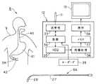
図2に示すように第1の参考例を備えたカプセル型内視鏡システム8は、患者9の体腔内を内視鏡検査するカプセル型内視鏡3Aと、このカプセル型内視鏡3Aが詰まったような場合に回収するための細長で可撓性を有する回収具5Aと、カプセル型内視鏡3Aにより電波で送信された信号を受けるアンテナ11を有し、受信した信号から画像信号を生成する体外受信ユニット12と、この体外受信ユニット12に接続され、画像を表示するモニタ13とを有する。
【0012】
図3に示すようにカプセル型内視鏡3Aは、円筒の両端を丸みを付けて閉塞した形状、つまりカプセル形状の透明カバー15で水密的に覆われている。この透明カバー15内で、撮像側となる前側の端部側の中央部分には結像光学系としての対物レンズ部組16が配置され、その結像位置には撮像素子として例えばCMOSイメージャ17が配置されている。
【0013】
また、対物レンズ部組16に隣接して、照明系としての例えば白色LED18と、回収のために設けた(第1の)永久磁石19とが配置されている。また、例えばCMOSイメージャ17の横、後ろ側には白色LED18を発光駆動させるLED駆動回路20、CMOSイメージャ17を駆動すると共に、CMOSイメージャ17の撮像信号から画像信号を生成する処理を行う駆動&処理回路21、例えば圧縮された画像信号を高周波変調してアンテナ22から送信すると共に、アンテナ22で受信した制御信号を復調して各回路を制御する送受信&制御回路23等が配置されている。
【0014】
上記LED駆動回路20、駆動&処理回路21、送受信&制御回路23の各回路は送受信&制御回路23の後端側に配置された例えば複数のボタン型電池24からの直流電源で動作するようになっている。
また、この透明カバー15の後端は肉厚にされ、アンテナ22と、回収のために設けた(第2の)永久磁石25とが後端内壁に接するようにして収納されている。なお、透明カバー15における永久磁石25に対向する部分の中央は凹部が形成されている。
【0015】
上記送受信&制御回路23における制御回路は、体外受信ユニット12側からの制御信号を受けると、例えば照明及び撮像の間隔等を変更できるようにしている。 例えば、カプセル型内視鏡3Aで検査しようとする対象部位に達するまでは、比較的長い間隔で照明及び撮像を行うようにし、対象部位に達した付近で、その間隔を短くするように制御することで、電池24による消耗を抑制して検査をしようとする部位で多くの画像を得ることができるようにしている。
【0016】
また、回収具5Aは例えば図2に示すように、イレウス状回収具であり、このイレウス状回収具5Aは細長のチューブ27の先端に先導子(先端ボール部)28を設けた構成である。
先導子28は内部に収納した金属球をシリコン樹脂等の可撓性の樹脂で覆うことにより、球状部材を複数連結した形状である。
【0017】
本参考例では、先導子28の内部構造は図3に示すように例えば先端側の2つの球状部材は球形永久磁石29をシリコン樹脂30で覆う構造にしてあり、これより後の部分ではステンレススチール等の金属球31をシリコン樹脂30で覆う構造にしている。
【0018】
そして、図3に示すように例えばカプセル型内視鏡3Aが小腸等の管腔臓器32内における狭窄部4で詰まり排出側に進まなくなった場合には、イレウス状回収具5Aを口腔側から挿入して、磁気的吸引力が働くようにしてカプセル型内視鏡3Aを体外に排出して回収できるようにしている。
【0019】
本参考例では、図4に示すようにカプセル内視鏡3Aの前端側の永久磁石19及び後端側の永久磁石25と、回収具5A側の永久磁石29との極は対向する側が互いに異なる極となるようにして、カプセル内視鏡3Aの前端側及び後端側とのいずれの方向から回収具5Aの先端側を近づけた場合にも、回収具5A側の永久磁石29との間で吸引力が作用するようにしている。
【0020】
図4の例では回収具5A側の先端の永久磁石29の磁極はNであり、従ってカプセル型内視鏡3Aの前端側に内蔵された永久磁石19の前端側の磁極はSであり、またカプセル型内視鏡3Aの後端側に内蔵された永久磁石25の後端側の磁極はSとなっている。
【0021】
また、カプセル型内視鏡3Aのアンテナ22から放射される電波を受け、画像信号を生成する体外受信ユニット12は、図2に示すようにアンテナ11は送受信回路33に接続され、アンテナ11から送られた信号を復調して制御回路34を介してハードディスク(HDDと略記)35に画像データを一旦格納する。
【0022】
そして、このHDD35に格納された画像データは画像処理回路36により伸張された画像データに変換され、メモリ37に格納され、このメモリ37の画像データはさらに表示回路38を介してモニタ13に表示可能な画像信号となり、モニタ13の表示面には、CMOSイメージャ17により撮像された画像が表示される。
【0023】
また、体外受信ユニット12にはキーボード39が設けてあり、カプセル型内視鏡3Aに対して照明及び撮像周期を変更させる制御コマンドを入力することにより、その制御コマンドが制御回路34、送受信回路33を経て変調され、アンテナ11から送信できるようにしている。
【0024】
そして、カプセル型内視鏡3Aはこの信号をアンテナ22で受け、送受信&制御回路23により復調して、照明及び撮像周期を変更する制御信号であると判断した場合には、それを受け取った返信信号を体外受信ユニット12側に送ると共に、LED駆動回路20、駆動&処理回路21(の駆動回路)とを制御し照明及び撮像の間隔を変更する動作状態に設定する。
【0025】
次に、このような構成のカプセル型内視鏡システム8の作用を説明する。
患者9はカプセル型内視鏡3Aで、例えば小腸の検査を行う場合、カプセル型内視鏡3Aを口から飲み込む。飲み込まれたカプセル型内視鏡3Aは図2に示すように(蠕動運動により)食道40、胃41を経て小腸42に達するようになる。
【0026】
小腸42に達するまでは、照明及び撮像の間隔はカプセル型内視鏡3Aに内蔵されたボタン型電池24による消耗を抑制し、かつカプセル型内視鏡3Aからの画像からカプセル型内視鏡3Aがどの付近に有るかをモニタできるような画像が得られるような間隔に設定する。
【0027】
例えば、数秒間に1回照明及び撮像を行う状態に設定する。医者或いは看護婦等の内視鏡検査スタッフは、カプセル型内視鏡3A側から送信され、体外受信ユニット12で受信され、モニタ13に表示される画像から、カプセル型内視鏡3Aが現在どの当たりに有るかを判断することができる。
【0028】
なお、モニタ13には、間欠的に受信した画像を次の画像を受信するまで静止画状に表示する。
【0029】
そして、小腸42付近に達したと判断した場合、キーボード39から照明及び撮像の間隔を短くする制御コマンドを入力し、カプセル型内視鏡3Aをより短い間隔で照明及び撮像を行うように変更する。照明及び撮像の間隔を短くすると、それに対応して、画像信号を送信する間隔も短くなる。
【0030】
従って、検査対象部位となる小腸42内をカプセル型内視鏡3Aが移動した際に撮像した画像が、短い間隔でモニタ13の表示面に順次表示されるようになる。そして、医者はその画像から診断することができる。なお、カプセル型内視鏡3Aから受け取った画像はHDD35に蓄積することができる。
【0031】
通常はこのようにして、カプセル型内視鏡3Aが小腸42内の移動と共に、得られる画像も変化し、小腸42から大腸側に移った場合には例えば照明及び撮像の間隔を長くするように制御する。そして、肛門から排出された場合には、このカプセル型内視鏡3Aを回収する。
【0032】
しかし、小腸42内に図3に示すような狭窄部4が存在し、カプセル型内視鏡3Aが移動できない状態になると、得られる画像も殆ど同じ画像となってしまう。このようになった場合には、イレウス状回収具5Aを口腔側から挿入して、この先端側をカプセル型内視鏡3Aに近づける。イレウス状回収具5Aは、例えば図示しない内視鏡のチャンネル内に挿通できる程度に細いので、内視鏡の挿入部を挿入しにくいような小腸内に容易に挿入することができる。
【0033】
そして、イレウス状回収具5Aの先端側をカプセル型内視鏡3Aに近づけることにより、そのイレウス状回収具5Aの先端部の先導子28の先端に設けた球形永久磁石29によりカプセル型内視鏡3Aの後端付近に内蔵した永久磁石25とで吸引力を発生し、図3に示すように両者が当接する状態になる。
【0034】
この状態で、イレウス状回収具5Aを引き抜くことにより、イレウス状回収具5Aの先端にカプセル型内視鏡3Aがほぼ当接した状態でカプセル型内視鏡3Aを体外に排出して回収できる。
【0035】
このように本参考例によれば、カプセル型内視鏡3Aが狭窄部4等で詰まり、移動できない状態になった場合にはイレウス状回収具5Aを挿入することで速やかにカプセル型内視鏡3Aを回収できる。
【0036】
なお、カプセル型内視鏡3Aに設けた例えば永久磁石19、25の代わりに鉄ブロック等、永久磁石29との間に磁気的吸引力が作用する(強)磁性体でも良い。
【0037】
次に本参考例の変形例を説明する。
図5は第1変形例のカプセル型内視鏡装置1Bを示す。第1の参考例ではイレウス状回収具5Aは永久磁石29を採用していたが、図5に示す第1変形例のイレウス状回収具5Bでは電磁石45を採用している。
【0038】
このイレウス状回収具5Bではチューブ27内には直流電力供給用の電線46が挿通され、チューブ27の先端の先導子28を形成する複数の球状の中空部を設けたシリコン樹脂30内には例えば複数の細い線状の鉄を束ねて屈曲し易くした鉄芯(図5では簡単化のため1本で示している)47が配置され、この鉄芯47に銅線等を巻き付けて形成したコイル48の両端を電線46に接続し、このコイル48に直流電力を供給することにより電磁石45として機能するようにしている。
【0039】
チューブ27の後端には、電線46とスイッチを介して図示しない電池(或いは直流電源)と接続され、スイッチをONすることによりコイル48に直流電力を供給することにより電磁石45を形成できるようにしている。また、電磁石45を形成した場合、その先端の磁極はN極となるようにして、カプセル型内視鏡3Aの向きが図3の場合でも、図5に示すように図3とは反対向きでカプセル型内視鏡3Aが狭窄部4に詰まった場合でも、カプセル型内視鏡3Aの永久磁石19或いは25との間に吸引力が発生するようにしている。その他は第1の参考例とほぼ同様の構成である。
また、本変形例の作用効果は第1の参考例とほぼ同様である。また、本変形例においても、例えば永久磁石19、25の代わりに鉄ブロック等、電磁石45との間に磁気的吸引力が作用する(強)磁性体でも良い。
【0040】
図6は第2変形例のカプセル型内視鏡装置1Cを示す。このカプセル型内視鏡装置1Cは管腔臓器32内に挿入されるカプセル型内視鏡3Cと、このカプセル型内視鏡3Cが狭窄部4等に詰まった場合に回収する紐状回収具5Cとを有し、また本変形例では紐状回収具5Cを挿入(或いはガイド)するために内視鏡51を用いている。
【0041】
この紐状回収具5Cは、紐状のワイヤ、チューブ、コイル等で形成した紐状部材52と、この紐状部材52の先端に設けた例えば球状の永久磁石53とを有する。
【0042】
また、内視鏡51は細長の挿入部の先端部54に図示しない照明光学系と、観察光学系55とが設けてあると共に、挿入部の長手方向に設けたチャンネル56内には紐状回収具5C等を挿通できるようにしている。
【0043】
そして、図6に示すようにカプセル型内視鏡3Cが管腔臓器32内の検査中に狭窄部4で詰まってしまったような場合には、口腔から内視鏡51を挿入し、この内視鏡51の観察下でそのチャンネル56内を挿通した紐状回収具5Cをカプセル型内視鏡3Cが有る部分付近までガイドするのに用いる。
【0044】
また、本変形例におけるカプセル型内視鏡3Cの構造を図7に拡大して示す。 このカプセル型内視鏡3Cは、円筒状でその両端を半球状にして覆うようにして透明カバー61を形成している。
【0045】
この透明カバー61内の中心軸上Oで、一方及び他方の端部側の中央位置には、(第1及び第2の)撮像回路62a、62bが配置され、その周囲に照明手段として(第1及び第2の)白色LED63a、63bがそれぞれ配置されている。撮像回路62a、62bは例えば第1の参考例における対物レンズ部組16及びCMOSイメージャ17で構成される。
【0046】
また、両撮像回路62a、62bの間には、撮像回路62a、62b及び白色LED63a、63bを駆動したり、撮像回路62a、62bの出力信号に対する信号処理等を行う複数の電子回路ブロック64と、複数の電子回路ブロック64に電源を供給するボタン型電池65が配置されている。
【0047】
また、この透明カバー61内で、複数の電子回路ブロック64及びボタン型電池65を囲むように円筒リング状の永久磁石66a、66bと、これら2つの永久磁石66a、66bの間に円筒リング状のアンテナ67とを配置している。
【0048】
このような構成のカプセル型内視鏡装置1Cにより、内視鏡検査を行う場合、カプセル型内視鏡3Cはそのカプセル容器の両端にそれぞれ第1及び第2の照明手段及び撮像手段が設けてあり、例えば交互に照明及び撮像を行い、また交互に撮像した信号を変調してアンテナ67から送信する。
【0049】
図示しない体外受信ユニット側では第1の参考例とほぼ同様に受信した信号を復調等してその画像信号をハードディスク等に記憶すると共に、モニタで表示する。
【0050】
仮に図6に示すようにカプセル型内視鏡3Cが狭窄部4で詰まった場合には、内視鏡51のチャンネル56内に紐状回収具5Cを挿通して、内視鏡51の観察下で、紐状回収具5Cをカプセル型内視鏡3Cの付近にまでガイドする。
【0051】
この場合、内視鏡51の挿入部を挿入できる部分では、内視鏡51の観察下で円滑な挿入を行う。つまり、紐状回収具5Cだけでは、挿入作業に熟練していない術者のような場合には、挿入に時間がかかる場合にも、内視鏡51の観察下では挿入作業がより容易となり、この内視鏡51を挿入できる部分まで挿入する。 そして、内視鏡51を挿入できる部分まで挿入したら、その先端部54から紐状回収具5Cの先端側をチャンネル56の先端から突出させる。
【0052】
図6に示すように紐状回収具5Cの先端側を、カプセル型内視鏡3Cが有る部分付近まで突出させることにより、紐状回収具5Cの先端の永久磁石53によりカプセル型内視鏡3C側の永久磁石66a、或いは66bとの間で吸引する磁力を発生させて回収することができる。
【0053】
本変形例によれば、両端にそれぞれ設けた撮像手段により、検査対象部位の内壁の状態をより詳しく撮像することができる等の効果がある。また、本参考例によれば、内視鏡51の観察下で紐状回収具5Cを回収のために挿入する場合、より円滑にカプセル型内視鏡3C付近(場合によってはその途中)までガイドすることができる。その他は第1の参考例と同様の効果を有する。
【0054】
なお、本変形例においても、例えば永久磁石66a、66bの代わりに鉄ブロック等、永久磁石53との間に磁気的吸引力が作用する(強)磁性体でも良い。 また、永久磁石53の代わりに電磁石でも良い。
【0055】
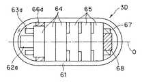
図8は第3変形例におけるカプセル型内視鏡3Dの構造を示す。このカプセル型内視鏡3Dは、図7とほぼ同様に、一方の端部側の撮像回路62aに隣接する電気回路ブロック64の外側に円筒リング状の永久磁石66aを配置し、他方の端部側の撮像回路62bを設ける代わりに平板状の永久磁石又は磁性体68を配置し、その周囲にリング状のアンテナ67を配置している。
【0056】
その他は図7のものと電子回路ブロック数等を変更しているが、ほぼ同様の構成である。本変形例は第1の参考例とほぼ同様の作用効果を有する。
【0057】
図9は第4変形例におけるカプセル型内視鏡3Eの構造を示す。このカプセル型内視鏡3Eは、図7のカプセル型内視鏡3Cにおいて、電子回路ブロック64及びボタン型電池65を囲むように円筒リング状の磁性体69を配置している。 また、撮像回路62bを設ける代わりにその位置にアンテナ67を配置している。その他は図7とほぼ同様の構成である。
【0058】
この変形例では円筒リング状の磁性体69は一方の端部から他方の端部に至る長い円筒リング形状にしている。なお、この磁性体69の代わりに長手方向に2分割して、両端側の磁極が同じになるようにした永久磁石を採用しても良い。
【0059】
本変形例の作用効果は第1の参考例とほぼ同様である。
なお、透明カバー15及び透明カバー16は、撮像光学系や照明光学系の前面部分のみが透明で、その他が不透明であっても良い。
【0060】
次に本発明の一実施の形態について説明する。
次に本発明の実施の形態を図10を参照して説明する。図10は本発明の実施の形態のカプセル型内視鏡装置をカプセル型内視鏡を体腔内に留置している状態で示す。
【0061】
図10に示すカプセル型内視鏡装置70は、体腔内71を検査するためのカプセル型内視鏡本体72及びこのカプセル型内視鏡本体72と柔軟な紐73を介して連結された略球形の永久磁石74とからなるカプセル型内視鏡75と、この永久磁石74との間の磁力でカプセル型内視鏡75を所望とする位置で留置するための別体の永久磁石76とから構成される。
【0062】
カプセル型内視鏡本体72は、そのカプセル状容器の先端側は透明なカバー77で覆われており、その内部に撮像手段78と照明手段79とが収納されている。また、撮像手段78の後方側には撮像手段78と照明手段79などを駆動したり、撮像した信号を送信する処理を行う図示しない電子回路、アンテナ、電池等が内蔵されている。
また、このカプセル型内視鏡本体72の後端には柔軟な紐73の一端が固着され、その他端には球状の永久磁石74が固着されている。
【0063】
このような構成によるカプセル型内視鏡装置70の作用を説明する。
通常の内視鏡検査の場合には、体外側の永久磁石74を使用しないで、カプセル型内視鏡75により体腔内71の検査を行う。そして、より詳しく検査したいような部位に達した場合には、図10に示すように体外から永久磁石76をその表面に押しつけて、永久磁石76により、永久磁石74との間に磁気吸引力が働くようにする。
【0064】
この磁気吸引力により、永久磁石74は永久磁石76に対向する付近に留置(或いは係止)されたアンカ磁石の状態となり、この状態でカプセル型内視鏡本体72は蠕動運動によりアンカ磁石を中心として動きまわり、その状態での撮像手段78で撮像された画像が体外側に送信され、内視鏡検査スタッフはその画像をモニタの画面で観察できる。
【0065】
そして、十分に所望とする部位の画像が得られたと判断した場合には、永久磁石76を除去することにより、通常のカプセル型内視鏡として再び内視鏡検査を行うようにできる。
【0066】
本実施の形態によれば、術者等は所望とする部位付近にカプセル型内視鏡本体72に一端が接続された紐73の他端の永久磁石74を留置(係止)できるようにしている(つまり遊びを持たせた状態でカプセル型内視鏡本体72を留置できるようにしている)ので、カプセル型内視鏡本体72は完全に動きが規制された状態ではなく、紐73の長さ程度の範囲で可動出来る状態で撮像を行うようになり、所望とする部位周辺の画像を得ることができる。
【0067】
なお、永久磁石74は永久磁石76の一方を磁性体にしても良い。また、永久磁石76の代わりに電磁石にしても良い。
【0068】
図11は本実施の形態の第1変形例におけるカプセル型内視鏡81を示す。このカプセル型内視鏡81は体腔内を検査するためのカプセル型内視鏡本体82及びこのカプセル型内視鏡本体82と一端が連結された柔軟な紐部83と、この紐部83の他端と連結された例えば磁性体としての鉄球84とからなる。
【0069】
このカプセル型内視鏡本体82は、そのカプセル状容器85の先端側は透明なカバー85aで覆われており、その内部に撮像手段86と照明手段87とが収納されている。また、撮像手段86の後方側には撮像手段86と照明手段87などを駆動したり、撮像した信号を送信する処理を行う電子回路(図11では簡単化のために単に回路と略記)88、アンテナ89、そして、これらの電気系に電源を供給する電池90が内蔵されている。
【0070】
また、このカプセル型内視鏡本体82の後端には半球状の凹部85bが形成され、鉄球84の一部がこの凹部85bに当接して収納され、その凹部85b周囲で係止手段としての例えばアゾポリマ91で接合されている。このアゾポリマ91は大腸に入るとその大腸内の細菌により作り出される特定の酵素で溶ける特性を有する。
【0071】
また、柔軟な紐73の一端及び他端はカプセル型内視鏡本体82の後端及び鉄球84にそれぞれ設けた紐収納用凹部で小さく収縮させた状態で収納している。 また、この凹部85bには電池90にリード線を介して電源スイッチ92のスイッチレバーが鉄球84で押圧されたOFFの状態で取り付けてある。
【0072】
この押圧が解除された状態になると、図示しないバネの弾性力でスイッチレバーが突出した状態となってONとなり、電子回路88などに電源が供給されるようにしている。つまり、図11(A)に示すように鉄球84により押圧された状態では電源スイッチ92はOFFに保たれており、このカプセル型内視鏡81が大腸に達すると、係止手段であるアゾポリマ91が解けて、図11(B)のように係止が解除される状態となる。また、図11(B)のようになると、圧縮等された収納されていた紐部83が伸び、図11(C)のようになる。
【0073】
このように係止解除の状態になると、凹部85bから鉄球84が外れ、この鉄球84により押圧されていた電源スイッチ92がONとなり、電池90の電源が電子回路88等に供給され、照明及び撮像等の動作が開始する。
【0074】
本実施の形態の当該変形例によれば、さらにカプセル型内視鏡81を飲み込み易い形状に保持でき、体腔内で検査対象となる部位(ここでは大腸)に達するとその電源をONさせることができるし、また必要に応じて本実施の形態と同様に体外からの永久磁石76等により係止させることもできる。
【0075】
(第2の参考例)
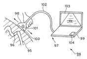
次に本発明の第2の参考例を図12及び図13を参照して説明する。図12は本発明の第2の参考例のカプセル型内視鏡装置94を示す。
このカプセル型内視鏡装置94は管腔内95を検査するカプセル型内視鏡96と、このカプセル型内視鏡96を誘導するための超音波プローブ装置97とを有する。この超音波プローブ装置97は、体外方式の超音波プローブ98と、この超音波プローブ98に接続されたポータブル超音波装置99とからなる。
【0076】
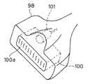
超音波プローブ98は図13に示すように、その前面には、内蔵された超音波素子100の超音波出射面100aが設けてあり、本参考例ではその付近にさらに電磁石101が設けてある。
【0077】
超音波素子100は超音波プローブ98のケーブル部102を介してポータブル超音波装置99に接続され、このポータブル超音波装置99からの超音波駆動信号が印加され、その信号の印加により超音波を出射し、その反射超音波を超音波素子100で受信して電気信号に変換し、ポータブル超音波装置99内部の受信信号処理回路で信号処理して超音波画像に変換し、モニタ部103で超音波断増像を表示する。
【0078】
また、電磁石101もケーブル部102内部の駆動線を介してポータブル超音波装置99と接続され、その操作部に設けたスイッチ104を操作することにより、電磁石101に直流電力をON/OFFできるようにしている。
【0079】
次にこのカプセル型内視鏡装置94の作用を説明する。
カプセル型内視鏡96により、管腔内95で内視鏡検査を行い、その進行の様子を超音波画像で観察しようとする場合、図12に示すように術者は超音波プローブ98を把持し、超音波プローブ装置97の電源をONして、患者の体表面に超音波出射面100aを押し当てて、モニタ部103に超音波画像を表示させ、体表面を移動させてカプセル型内視鏡96の画像が得られる状態にする。
【0080】
そして、例えば屈曲の激しい管腔部分のために進行が遅いような場合には、スイッチ104をONして、電磁石101として機能する状態に設定し、カプセル型内視鏡96に内蔵された永久磁石或いは磁性体との間でカプセル型内視鏡96を移動させる方向に磁力が働くように操作する。
【0081】
本参考例によれば、超音波画像でカプセル型内視鏡96をその管腔部分と共に観察できると共に、電磁石101により、所望とする方向への誘導もできるという効果がある。また、本参考例によれば、小型で携帯使用に適し、広範囲に利用できる。
【0082】
(第3の参考例)
次に本発明の第3の参考例を図14を参照して説明する。図14は本発明の第3の参考例のカプセル型医療装置111を示す。
このカプセル型医療装置111は、円筒部分とその両端を丸く覆ったカバーで水密構造のカプセル本体112が形成され、その一方の端部側に体腔内の例えばpHを検出するpHセンサ113の検出部を突出(或いは露出)するように設けている。
このpHセンサ113の検出部をカプセル本体112の孔部から突出させる場合、水密機能が高い接着剤で固定して内部を水密構造にしている。
【0083】
このpHセンサ113の後端側はカプセル本体112内部に設けたpH検出の処理や検出したPHのデータを蓄積したり、外部に送信する通信手段等の機能を備えた回路基板114と接続されている。また、この回路基板114はこの回路基板114を動作させる電源を供給する電池115と接続されている。
【0084】
また、本参考例では、カプセル本体112内には、pHセンサ113と反対側の端部付近に永久磁石或いは磁性体116を収納している。
【0085】
そして、例えば第1の参考例等で説明した回収具によって、このカプセル型医療装置111が狭窄部等で詰まったような場合には回収できるようにしている。
【0086】
本参考例では医療用検査手段として、pHを検出するpHセンサ113を採用しているが、この他に温度センサ、圧力センサ、光センサ、又は血液センサ(具体的にはヘモグロビン検出用センサ)等を採用しても良い。
【0087】
このように本参考例ではセンサ部分(検出部)により、生体内液の化学量(pH値)、各臓器の温度、カプセル通過時のカプセル外面にかかる管腔内面からの圧力、生体内の明るさ、各臓器のヘモグロビン量(出血の有無)等の情報を入手し、得られたデータは図示しないカプセル内部のメモリに一旦、蓄積され、その後、図示しない通信手段により体外に置かれている受信手段に送信される。 そして、受信手段により得られたデータを基準値と比較することで、病気や出血等の異常の有無の判断、カプセル通過位置や通過状態の判断を体外において、医者やコメディカル等の医療従事者が行うことができる。
【0088】
特に、カプセル型医療装置により被検者は苦痛なく、生体の消化管内部のpH値やヘモグロビン量等を測定することができ、消化器疾患の診断や生理学的解析を行えることの効果が大きい。各種センサは、目的に応じて複数種類用意することで、効率良い検査を行うことができる。
【0089】
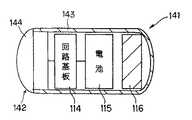
また、図14では各種センサを設けたカプセル型医療装置111を説明したが、各種センサの代わりに図15に示すように超音波探触子142を設けたカプセル型医療装置141でも良い。
【0090】
このカプセル型医療装置141では、カプセル本体143の例えば前面には超音波探触子142の前面に設けた音響レンズ144がカプセル本体143の外面に露出するように配置され、音響レンズ144はカプセル本体143に接着剤等により水密的に固定され、カプセル内部は水密構造になっている。
【0091】
超音波探触子142の裏面側のカプセル内部には、超音波送受信回路や、その信号から超音波断像を生成する処理等を行う回路基板114が配置され、回路基板114は電池115からの電源で駆動する。また、後端側には永久磁石116が収納されている。
【0092】
このカプセル型医療装置141では、回路基板114により形成される超音波送受信回路により体腔内の超音波断層像が生成され、得られたデータは図14の場合と同様に、体外の受信手段に送信される。これにより、小腸等、体腔内深部の深さ方向の異常の有無の診断が行える。
光学的な観察手段(撮像手段)と両方を備えても良く、そのような構成にすれば、体腔内表面と深部との診断を一度に行える。
【0093】
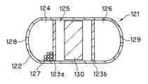
図16は第2変形例のカプセル型医療装置121を示す。
このカプセル型医療装置121は、円筒とその両端を丸く覆ったカバーでカプセル本体122を形成し、さらにカプセル本体122を長手方向の2箇所でそれぞれ仕切部材123a、123bで仕切り、薬剤収納部124、永久磁石/磁性体収納部125、体液吸入部126との3つの収納手段を形成している。
【0094】
薬剤収納部124には治療のための薬剤127を収納し、また収納した薬剤127を外部に放出するための開口手段としての投薬口128が設けてある。
【0095】
また、この薬剤収納部124と反対側に設けた体液吸入部126にも、このカプセル本体122外部からの体液を吸入するための体液吸入口129が設けてある。
【0096】
また、永久磁石/磁性体収納部125には永久磁石或いは磁性体130が収納されている。
投薬口128及び体液吸入口129の開口は、胃液により消化されるゼラチンや腸液で消化される脂肪酸膜等からなる溶解膜128a、129aが設けてある。
【0097】
そして、目的部位にカプセル型医療装置121が到達したら、溶解膜128a等が消化されて治療用の薬剤127の投与や、体液の吸入を行うことができる。 このように本変形例によれば、目的部位で治療や検査のための体液の吸入等を行うことができる。
【0098】
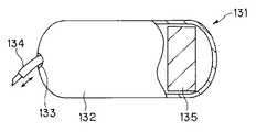
図17は第3変形例のカプセル型医療装置131を示す。
このカプセル型医療装置131は、円筒とその両端を丸く覆ったカバーでカプセル本体132を形成し、その一方の端部側には開口133を設けて、例えば薬剤注入用注射針134を突没自在にしている。このカプセル本体132内部には、この薬剤注入用注射針134を突没する駆動手段と、その制御手段が配置され、外部から制御信号を送ることにより、薬剤注入用注射針134を突没して、薬剤を注入できるようにしている。
また、カプセル本体132内部における開口133と反対側の端部付近に永久磁石或いは磁性体135を収納している。
【0099】
血液センサや観察手段で出血部位を確認後、体外からの通信によりカプセル内部に収納した止血剤注入針等の処置具を動作を指示し、止血剤であるエタノールや粉末薬品を出血部位に散布して止血することができる。
【0100】
本変形例によれば、止血等の処置を行うことができる。
【0101】
[付記]
1.人又は動物の体腔管路内を通過させて検査、治療又は処置を行うカプセル型医療装置において、
永久磁石又は磁性体を具備したカプセル本体と、先端付近に永久磁石又は電磁石を具備して、前記カプセル本体との間に吸引力を発生させる回収具とからなるカプセル型医療装置。
【0102】
1a.付記1において、カプセル内の磁石の外周側の極と回収具の極とが引き合う方向となるように配置した。
2.前記回収具は、細長の可撓性部材の先端付近に永久磁石又は電磁石を具備していることを特徴とする請求項1記載のカプセル型医療装置。
2a.付記2において、回収具は、イレウスチューブ又はイレウスチューブ状挿入具の先端に永久磁石又は電磁石を具備している。
【0103】
2b.付記2において、回収具は、内視鏡チャンネル内を通る紐状の挿入具の先端に永久磁石又は電磁石を具備している。
3.前記カプセル本体が体腔内でどちらの向きに詰まっても回収できるように、カプセル本体の両端付近に永久磁石又は磁性体を具備したことを特徴とする請求項1記載のカプセル型医療装置。
3a.付記3において、カプセルの長軸方向中心線に対して、前後の両方に永久磁石又は磁性体を収納し、前記永久磁石又は磁性体の形状がリング状である。
【0104】
3b.付記3において、カプセルの長軸方向中心線に対して、前後の両方に 永久磁石又は磁性体を収納し、前記永久磁石又は磁性体の形状が一方はリング状で、他方は平板状である。
3c.付記3において、カプセルの長軸方向に円筒状の永久磁石又は磁性体を収納した。
4.検査、治療又は処置する機能を備えたカプセル本体と、これとは別体の永久磁石又は磁性体と、両者を結ぶ紐状の連結手段と、外部の磁力発生手段よりなるカプセル医療システム。
【0105】
4a.付記4において、カプセル本体は照明手段と観察(撮像)手段を備えたカプセル型内視鏡である。
4c.付記4において、外部の磁力発生手段は前記永久磁石又は磁性体との間の磁力により前記カプセル本体を係止する係止手段を形成する。
4d.付記4cにおいて、上記係止手段は体腔内の特定の部位で外れ、同時にスイッチが入るようにしたことを特徴とする。
【0106】
(付記4〜4dの背景)
従来のカプセル型内視鏡では、蠕動運動により動かすようにしているので、見たい所で止めるようなことができなかった。一方、磁気誘導で位置制御するアイデアもあるが、その場合には磁気引力によりカプセル内視鏡が管腔に密着されてしまうので、適切な視野が得られなかった(視野が遮られてしまう欠点がある)。
(目的)
視野が遮られることなく、カプセルを係止して適切な視野を得ることができるカプセル医療システム(特にカプセル内視鏡システム)を提供することを目的とする。
【0107】
5.ポータブルな体外超音波プローブの一部に誘導用電磁石を付加し、超音波で内部臓器を観察しながら磁気誘導できるようにした超音波プローブ装置。
(付記5の背景)
カプセルを体外から磁気誘導する際に、X線透視下等の位置検出手段と組み合わせることが従来例で開示されている。
しかし、X線装置等の大型の装置と組み合わせたのでは、カプセルで検査する場所が制約されてしまう欠点がある。
(目的)
カプセルを体外から誘導でき、携帯性に優れた小型にできる超音波プローブ装置を提供することを目的とする。
【0108】
【発明の効果】
以上説明したように本発明によれば、視野が遮られることなく、カプセル本体を係止して適切な視野を得ることができる効果がある。
【図面の簡単な説明】
【図1】本発明の第1の参考例のカプセル型内視鏡装置の概略の構成を示す図。
【図2】第1の参考例を備えたカプセル型内視鏡システムの構成を示すブロック図。
【図3】第1の参考例の主要部の構成を使用例で示す図。
【図4】磁極の向きを示す図。
【図5】第1の参考例の第1変形例のカプセル型内視鏡装置の主要部の構成を使用例で示す図。
【図6】第1の参考例の第2変形例のカプセル型内視鏡装置の主要部の構成を使用例で示す図。
【図7】カプセル型内視鏡の構成を示す断面図。
【図8】第1の参考例の第3変形例のカプセル型内視鏡の構成を示す断面図。
【図9】第1の参考例の第4変形例のカプセル型内視鏡の構成を示す断面図。
【図10】本発明の実施の形態のカプセル型内視鏡装置の概略の構成を使用例で示す図。
【図11】本実施の形態の変形例のカプセル型内視鏡の内部構成等を示す図。
【図12】本発明の第2の参考例のカプセル型内視鏡装置の概略の構成を使用例で示す図。
【図13】超音波プローブ部分を示す斜視図。
【図14】本発明の第3の参考例のカプセル型内視鏡装置の構成を示す断面図。
【図15】第3の参考例の第1変形例のカプセル型医療装置の構成を示す断面図。
【図16】第3の参考例の第2変形例のカプセル型医療装置の構成を示す断面図。
【図17】第3の参考例の第3変形例のカプセル型医療装置の構成を示す図。
【符号の説明】
1…カプセル型内視鏡装置
2…管腔臓器
3…カプセル型内視鏡
4…狭窄部
5…回収具
6…永久磁石
7…永久磁石
8…カプセル型内視鏡システム
9…患者
11…アンテナ
12…体外受信ユニット
13…モニタ
15…透明カバー
16…対物レンズ部組
17…CMOSイメージャ
18…白色LED
19…永久磁石
20…LED駆動回路
21…駆動&処理回路
22…アンテナ
23…送受信&制御回路
24…電池
27…チューブ
28…先導子
29…永久磁石
30…樹脂
31…金属球[0001]
BACKGROUND OF THE INVENTION
The present invention relates to a capsule medical system in which the inside of a body cavity is inspected by a capsule body incorporating an imaging means and the like.
[0002]
[Prior art]
In recent years, endoscopes and other medical devices for examining the inside of a body cavity or the like have been proposed. In addition, in a normal endoscope, only an insertion portion is inserted into a body cavity to perform an endoscopic examination or the like, but an endoscope in which a capsule-shaped capsule body is inserted into a body cavity to perform an examination or the like. Proposed.
[0003]
In such a capsule medical device, the capsule main body may be clogged in the body cavity. For example, in the swallowable endoscope device disclosed in Japanese Patent Laid-Open No. 2000-342522, the end of the swallowable endoscope main body of a rod-shaped body is used. An apparatus in which an endoscope grasping forceps or the like is inserted into a hook portion (hole) provided in the portion and forcibly pulled up is disclosed.
[0004]
[Problems to be solved by the invention]
In the conventional capsule endoscope, since it is moved by a peristaltic motion, it cannot be stopped at a desired place. On the other hand, there is an idea of position control by magnetic induction, but in this case, the capsule endoscope is brought into close contact with the lumen due to magnetic attraction, so that an appropriate visual field cannot be obtained (the disadvantage that the visual field is blocked). there were).
[0005]
(Object of invention)
The present invention has been made in view of the above-described points, and an object of the present invention is to provide a capsule medical system that can obtain an appropriate visual field by locking the capsule body without obstructing the visual field.
[0006]
[Means for Solving the Problems]
The capsule medical system of the present invention is introduced into a subject, and has a function of executing examination, treatment, or treatment inside the subject, and a permanent magnet or magnet that is separate from the capsule body. It is characterized by comprising a body, a string-like connecting means for connecting the capsule body and the separate permanent magnet or magnetic body, and an external magnetic force generating means.
[0007]
DETAILED DESCRIPTION OF THE INVENTION
Embodiments of the present invention will be described below with reference to the drawings.
[0008]
Prior to the description of the embodiments of the present invention, a reference example for reference of the capsule endoscope apparatus of the present invention will be described.
(First reference example)
1 to 9 show the present invention.First reference example1 is related toFirst reference exampleFIG. 2 shows a schematic configuration of the capsule endoscope apparatus of FIG.First reference exampleFIG. 3 shows a configuration of a capsule endoscope system provided withFirst reference exampleFIG. 4 shows the orientation of the magnetic poles, FIG. 5 shows the configuration of the main part of the capsule endoscope apparatus of the first modified example, and FIG. 6 shows the second example. FIG. 7 shows the configuration of the capsule endoscope, and FIG. 8 shows the configuration of the capsule endoscope of the third modified example. FIG. 9 shows a configuration of a capsule endoscope according to a fourth modification.
[0009]
As shown in FIG. 1, the capsule medical device of the present inventionFirst reference exampleThe capsule endoscope apparatus 1 includes a capsule endoscope 3 that is inserted into a human or animal luminal organ 2 and performs endoscopy during movement by a peristaltic motion, and the capsule endoscope. In the case where 3 is clogged with the
[0010]
The capsule endoscope 3 incorporates illumination and observation (imaging) means, which will be described later, and is provided with, for example, a permanent magnet 7 that is attracted by, for example, a permanent magnet 6 provided at the tip of the
[0011]
Hereinafter, a more specific configuration and the like will be described with reference to FIG.
As shown in FIG.First reference exampleThe capsule endoscope system 8 including the
[0012]
As shown in FIG. 3, the
[0013]
In addition, for example, a
[0014]
The
The rear end of the
[0015]
When receiving a control signal from the
[0016]
For example, as shown in FIG. 2, the
The
[0017]
Reference exampleThen, as shown in FIG. 3, for example, the two spherical members on the tip side have a structure in which the spherical
[0018]
Then, as shown in FIG. 3, for example, when the
[0019]
Reference exampleThen, as shown in FIG. 4, the poles of the
[0020]
In the example of FIG. 4, the magnetic pole of the
[0021]
The
[0022]
The image data stored in the
[0023]
The
[0024]
The
[0025]
Next, the operation of the capsule endoscope system 8 having such a configuration will be described.
The patient 9 is a
[0026]
Until reaching the
[0027]
For example, it sets to the state which performs illumination and imaging once in several seconds. An endoscopy staff, such as a doctor or a nurse, sends information from the
[0028]
The
[0029]
When it is determined that the vicinity of the
[0030]
Accordingly, images captured when the
[0031]
Normally, in this way, when the
[0032]
However, when the
[0033]
Then, by bringing the distal side of the ileus-
[0034]
In this state, by pulling out the ileus-
[0035]
in this wayReference exampleAccording to the above, when the
[0036]
In addition, instead of the
[0037]
nextReference exampleA modified example will be described.
FIG. 5 shows a capsule endoscope apparatus 1B according to a first modification.First reference exampleIn FIG. 5, the ileus-
[0038]
In the ileus-
[0039]
The rear end of the
Also,This modificationThe effect ofFirst reference exampleIs almost the same. Also in this modification, for example, instead of the
[0040]
FIG. 6 shows a
[0041]
The string-
[0042]
The
[0043]
Then, as shown in FIG. 6, when the
[0044]
Further, the structure of the capsule endoscope 3C in the present modification is shown in an enlarged manner in FIG. The capsule endoscope 3C is cylindrical and has a
[0045]
On the central axis O in the
[0046]
In addition, a plurality of electronic circuit blocks 64 that drive the
[0047]
Further, in the
[0048]
When performing endoscopy with the
[0049]
On the external receiving unit side (not shown)First reference exampleThe received signal is demodulated and stored in a hard disk or the like and displayed on a monitor in substantially the same manner as in FIG.
[0050]
If the
[0051]
In this case, in a portion where the insertion portion of the
[0052]
As shown in FIG. 6, the capsule-
[0053]
According to this modification, there is an effect that the state of the inner wall of the region to be inspected can be imaged in more detail by the imaging means provided at both ends. Also,Reference exampleAccording to the above, when the string-
[0054]
In this modified example, a (strong) magnetic material in which a magnetic attractive force acts between the
[0055]
FIG. 8 shows the structure of a
[0056]
Other than that, the number of electronic circuit blocks and the like are changed from those in FIG. 7, but the configuration is almost the same. This variation isFirst reference exampleHave substantially the same effect.
[0057]
FIG. 9 shows the structure of a
[0058]
In this modification, the cylindrical ring-shaped
[0059]
The effect of this modification isFirst reference exampleIs almost the same.
Note that the
[0060]
Next, an embodiment of the present invention will be described.
nextEmbodiment of the present inventionWill be described with reference to FIG. FIG.Embodiment of the present inventionThis capsule endoscope apparatus is shown in a state where the capsule endoscope is placed in a body cavity.
[0061]
A
[0062]
The capsule endoscope
One end of a
[0063]
The operation of the
In the case of normal endoscopy, the inside of the body cavity 71 is inspected by the
[0064]
Due to this magnetic attractive force, the
[0065]
When it is determined that an image of a desired portion is sufficiently obtained, the
[0066]
According to the present embodiment, the operator or the like can place (lock) the
[0067]
The
[0068]
FIG.Of this
[0069]
In the capsule endoscope
[0070]
Further, a
[0071]
Further, one end and the other end of the
[0072]
When the pressure is released, the switch lever protrudes with the elastic force of a spring (not shown) and is turned on so that power is supplied to the
[0073]
In this unlocked state, the
[0074]
This modification of the present embodimentAccording to the above, the
[0075]
(Second reference example)
Next, the present inventionSecond reference exampleWill be described with reference to FIGS. FIG. 12 shows the present invention.Second reference example1 shows a
The
[0076]
As shown in FIG. 13, the
[0077]
The
[0078]
Further, the
[0079]
Next, the operation of the
When performing endoscopy in the
[0080]
For example, when the progress is slow due to a severely bent lumen portion, the
[0081]
Reference exampleAccording to the above, it is possible to observe the
[0082]
(Third reference example)
Next, the present inventionThird reference exampleWill be described with reference to FIG. FIG. 14 shows the present invention.Third reference exampleThe capsule type
In this capsule
When the detection part of the
[0083]
The rear end side of the
[0084]
Also,Reference exampleThen, in the
[0085]
And for exampleFirst reference exampleWith the recovery tool described above, the capsule
[0086]
Reference exampleIn this case, a
[0087]
in this wayReference exampleIn the sensor part (detection part), the chemical amount (pH value) of the liquid in the living body, the temperature of each organ, the pressure from the inner surface of the lumen applied to the outer surface of the capsule when passing through the capsule, the brightness in the living body, the hemoglobin of each organ Information such as the amount (whether bleeding is present) is obtained, and the obtained data is temporarily stored in a memory inside a capsule (not shown), and then transmitted to a receiving means placed outside the body by a communication means (not shown). Then, by comparing the data obtained by the receiving means with the reference value, it is possible to determine whether there is an abnormality such as illness or bleeding, and to determine the capsule passage position and passage state outside of the body, such as a medical worker such as a doctor or comedy. Can be done.
[0088]
In particular, the capsule medical device can measure the pH value and the amount of hemoglobin in the digestive tract of a living body without pain, and can greatly diagnose gastrointestinal diseases and perform physiological analysis. Various types of sensors can be efficiently tested by preparing a plurality of types according to the purpose.
[0089]
14 describes the capsule
[0090]
In this capsule
[0091]
Inside the capsule on the back side of the
[0092]
In this capsule
Both optical observation means (imaging means) may be provided. With such a configuration, diagnosis of the body cavity surface and the deep part can be performed at a time.
[0093]
FIG. 16 shows a capsule
This capsule type
[0094]
The
[0095]
Further, a body
[0096]
The permanent magnet / magnetic
Dissolving films 128a and 129a made of gelatin digested by gastric juice, fatty acid films digested by intestinal fluid, or the like are provided at the openings of the
[0097]
When the capsule
[0098]
FIG. 17 shows a capsule
In this capsule
Further, a permanent magnet or a
[0099]
After confirming the bleeding site with a blood sensor or observation means, instruct the operation of a treatment tool such as a hemostatic agent injection needle housed inside the capsule by communication from outside the body, and spray ethanol or powdered medicine as a hemostatic agent on the bleeding site. Can stop bleeding.
[0100]
According to this modification, treatment such as hemostasis can be performed.
[0101]
[Appendix]
1. In a capsule medical device that performs inspection, treatment or treatment by passing through a body cavity duct of a human or animal,
A capsule medical device comprising: a capsule body having a permanent magnet or a magnetic body; and a recovery tool that has a permanent magnet or an electromagnet near the tip and generates an attractive force between the capsule body.
[0102]
1a. In Supplementary Note 1, the poles on the outer peripheral side of the magnet in the capsule and the poles of the recovery tool are arranged to be attracted to each other.
2. 2. The capsule medical device according to claim 1, wherein the recovery tool includes a permanent magnet or an electromagnet in the vicinity of the tip of the elongated flexible member.
2a. In Supplementary Note 2, the recovery tool includes a permanent magnet or an electromagnet at the tip of the ileus tube or ileus tube-shaped insertion tool.
[0103]
2b. In Supplementary Note 2, the recovery tool includes a permanent magnet or an electromagnet at the tip of a string-like insertion tool that passes through the endoscope channel.
3. 2. The capsule medical device according to claim 1, further comprising a permanent magnet or a magnetic body in the vicinity of both ends of the capsule body so that the capsule body can be collected regardless of which direction the capsule body is clogged in the body cavity.
3a. In Supplementary Note 3, a permanent magnet or a magnetic material is housed in both the front and rear with respect to the long axis direction center line of the capsule, and the shape of the permanent magnet or the magnetic material is a ring shape.
[0104]
3b. In Supplementary Note 3, a permanent magnet or a magnetic body is housed in both the front and rear with respect to the center line in the longitudinal direction of the capsule, and one of the shape of the permanent magnet or the magnetic body is a ring shape and the other is a flat plate shape.
3c. In Supplementary Note 3, a cylindrical permanent magnet or magnetic body was accommodated in the long axis direction of the capsule.
4). A capsule medical system comprising a capsule body having a function of examining, treating or treating, a separate permanent magnet or magnetic body, a string-like connecting means for connecting both, and an external magnetic force generating means.
[0105]
4a. In
4c. In
4d. In Supplementary Note 4c, the locking means is disengaged at a specific site in the body cavity and is switched on at the same time.
[0106]
(Background of appendix 4-4d)
In the conventional capsule endoscope, since it is moved by a peristaltic motion, it cannot be stopped at a desired place. On the other hand, there is an idea of position control by magnetic induction, but in this case, the capsule endoscope is brought into close contact with the lumen due to magnetic attraction, so that an appropriate visual field cannot be obtained (disadvantage that the visual field is blocked). There is).
(the purpose)
It is an object of the present invention to provide a capsule medical system (particularly a capsule endoscope system) that can obtain an appropriate visual field by locking a capsule without obstructing the visual field.
[0107]
5. An ultrasonic probe device that adds a guiding electromagnet to a part of a portable extracorporeal ultrasonic probe and allows magnetic induction while observing the internal organs with ultrasonic waves.
(Background to Appendix 5)
A conventional example discloses that a capsule is combined with position detection means such as under fluoroscopy when magnetically guiding a capsule from outside the body.
However, when combined with a large-sized apparatus such as an X-ray apparatus, there is a drawback that the place to inspect with a capsule is restricted.
(the purpose)
It is an object of the present invention to provide an ultrasonic probe apparatus that can guide a capsule from outside the body and can be miniaturized with excellent portability.
[0108]
【The invention's effect】
As described above, according to the present invention, there is an effect that an appropriate visual field can be obtained by locking the capsule body without blocking the visual field.
[Brief description of the drawings]
FIG. 1 of the present inventionFirst reference exampleFIG. 2 is a diagram showing a schematic configuration of the capsule endoscope apparatus of FIG.
[Figure 2]First reference exampleThe block diagram which shows the structure of a capsule type endoscope system provided with this.
[Fig. 3]First reference exampleThe figure which shows the structure of the principal part of by an example of use.
FIG. 4 is a diagram showing the direction of magnetic poles.
[Figure 5]Of the first reference exampleThe figure which shows the structure of the principal part of the capsule endoscope apparatus of a 1st modification by a usage example.
[Fig. 6]Of the first reference exampleThe figure which shows the structure of the principal part of the capsule type endoscope apparatus of a 2nd modification by a usage example.
FIG. 7 is a cross-sectional view showing a configuration of a capsule endoscope.
[Fig. 8]Of the first reference exampleSectional drawing which shows the structure of the capsule endoscope of a 3rd modification.
FIG. 9Of the first reference exampleSectional drawing which shows the structure of the capsule type endoscope of a 4th modification.
FIG. 10Embodiment of the present inventionThe figure which shows the schematic structure of the capsule type | mold endoscope apparatus of an example with a usage example.
FIG. 11Modification of the present embodimentThe figure which shows the internal structure etc. of the capsule type endoscope of this.
FIG. 12 shows the present invention.Second reference exampleThe figure which shows the schematic structure of the capsule type | mold endoscope apparatus of an example with a usage example.
FIG. 13 is a perspective view showing an ultrasonic probe portion.
FIG. 14 shows the present invention.Third reference exampleSectional drawing which shows the structure of the capsule type endoscope apparatus of this.
FIG. 15Of the third reference exampleSectional drawing which shows the structure of the capsule type medical device of a 1st modification.
FIG. 16Of the third reference exampleSectional drawing which shows the structure of the capsule type medical device of a 2nd modification.
FIG. 17Of the third reference exampleThe figure which shows the structure of the capsule type medical device of a 3rd modification.
[Explanation of symbols]
1 ... Capsule endoscope device
2 ... luminal organs
3 ... Capsule endoscope
4 ... Stenosis
5 ... Recovery tool
6 ... Permanent magnet
7 ... Permanent magnet
8 ... Capsule endoscope system
9 ... Patient
11 ... Antenna
12 ... Extracorporeal receiving unit
13 ... Monitor
15 ... Transparent cover
16 ... Objective lens assembly
17 ... CMOS imager
18 ... White LED
19 ... Permanent magnet
20 ... LED drive circuit
21 ... Drive & processing circuit
22 ... Antenna
23. Transmission / reception & control circuit
24 ... Battery
27 ... Tube
28 ... Leader
29 ... Permanent magnet
30 ... resin
31 ... Metal ball
Claims (6)
Translated fromJapanese前記カプセル本体とは別体の永久磁石又は磁性体と、
前記カプセル本体と前記別体の永久磁石又は磁性体とを結ぶ紐状の連結手段と、
外部の磁力発生手段と、
を備えたことを特徴とするカプセル型医療システム。A capsule body that is introduced into a subject and has a function of performing examination, treatment, or treatment inside the subject;
A permanent magnet or magnetic body separate from the capsule body;
A string-like connecting means for connecting the capsule body and the separate permanent magnet or magnetic body;
An external magnetic force generation means;
A capsule-type medical system comprising:
前記収容部に前記別体の永久磁石又は磁性体を収容した際に前記収容部と前記別体の永久磁石又は磁性体とが接する壁面に、前記カプセル本体の電源ON/OFF動作を行うスイッチ手段を備えることを特徴とする請求項5に記載のカプセル型医療システム。The capsule body has a housing portion that houses the separate permanent magnet or magnetic body,
Switch means for performing a power ON / OFF operation of the capsule body on the wall surface where the housing part and the separate permanent magnet or magnetic body are in contact with each other when the separate permanent magnet or magnetic body is housed in the housing part The capsule medical system according to claim 5, further comprising:
Priority Applications (1)
| Application Number | Priority Date | Filing Date | Title |
|---|---|---|---|
| JP2001289560AJP4578740B2 (en) | 2001-09-21 | 2001-09-21 | Capsule medical device |
Applications Claiming Priority (1)
| Application Number | Priority Date | Filing Date | Title |
|---|---|---|---|
| JP2001289560AJP4578740B2 (en) | 2001-09-21 | 2001-09-21 | Capsule medical device |
Publications (3)
| Publication Number | Publication Date |
|---|---|
| JP2003093332A JP2003093332A (en) | 2003-04-02 |
| JP2003093332A5 JP2003093332A5 (en) | 2007-11-29 |
| JP4578740B2true JP4578740B2 (en) | 2010-11-10 |
Family
ID=19112031
Family Applications (1)
| Application Number | Title | Priority Date | Filing Date |
|---|---|---|---|
| JP2001289560AExpired - Fee RelatedJP4578740B2 (en) | 2001-09-21 | 2001-09-21 | Capsule medical device |
Country Status (1)
| Country | Link |
|---|---|
| JP (1) | JP4578740B2 (en) |
Families Citing this family (34)
| Publication number | Priority date | Publication date | Assignee | Title |
|---|---|---|---|---|
| US20050124875A1 (en)* | 2003-10-01 | 2005-06-09 | Olympus Corporation | Vivo observation device |
| JP4503979B2 (en)* | 2003-10-22 | 2010-07-14 | オリンパス株式会社 | Internal devices and medical devices |
| WO2006070472A1 (en)* | 2004-12-28 | 2006-07-06 | Olympus Corporation | Introduction aiding apparatus for encapsulated medical device |
| JP2005253798A (en)* | 2004-03-12 | 2005-09-22 | Olympus Corp | Internally introduced device in subject |
| JP4663278B2 (en)* | 2004-08-20 | 2011-04-06 | オリンパス株式会社 | Receiving apparatus and in-subject introduction system |
| JP2006230906A (en)* | 2005-02-28 | 2006-09-07 | Toshiba Corp | Medical diagnostic system, medical diagnostic apparatus, and endoscope |
| JP4505360B2 (en)* | 2005-03-23 | 2010-07-21 | オリンパスメディカルシステムズ株式会社 | Device for detecting and holding a magnetic substance indwelling device |
| CN101184523B (en) | 2005-05-27 | 2011-04-13 | 奥林巴斯株式会社 | Device introduced into the subject |
| JP4839034B2 (en)* | 2005-07-20 | 2011-12-14 | オリンパス株式会社 | In vivo information acquisition device indwelling system |
| EP1905345A4 (en) | 2005-07-20 | 2012-04-25 | Olympus Medical Systems Corp | APPARATUS AND SYSTEM FOR RETAINING AN INTRODUCTION DEVICE IN A BODY CAVITY |
| JP4959965B2 (en)* | 2005-09-29 | 2012-06-27 | オリンパス株式会社 | Body cavity introduction device placement system |
| JP4914600B2 (en)* | 2005-11-10 | 2012-04-11 | オリンパスメディカルシステムズ株式会社 | In-vivo image acquisition device, reception device, and in-vivo information acquisition system |
| JP5064018B2 (en)* | 2005-12-28 | 2012-10-31 | オリンパスメディカルシステムズ株式会社 | Intra-subject introduction system |
| WO2007078003A1 (en)* | 2006-01-06 | 2007-07-12 | Olympus Medical Systems Corp. | Trans-natural opening based or transcutaneous medical system |
| US20080015413A1 (en)* | 2006-02-22 | 2008-01-17 | Olympus Medical Systems Corporation | Capsule endoscope system and medical procedure |
| JP4936528B2 (en)* | 2007-03-28 | 2012-05-23 | 富士フイルム株式会社 | Capsule endoscope system and method for operating capsule endoscope system |
| DE602009001050D1 (en) | 2008-06-04 | 2011-05-26 | Olympus Medical Systems Corp | Capsular medical device |
| JP5527207B2 (en)* | 2008-07-10 | 2014-06-18 | 学校法人自治医科大学 | Medical device indwelling device |
| US20120165796A1 (en)* | 2010-12-22 | 2012-06-28 | Ethicon Endo-Surgery, Inc. | Pill Catchers |
| US20120165792A1 (en)* | 2010-12-22 | 2012-06-28 | Ethicon Endo-Surgery, Inc. | Pill Catchers |
| US20120165794A1 (en)* | 2010-12-22 | 2012-06-28 | Ethicon Endo-Surgery, Inc. | Pill Catchers |
| JP5722188B2 (en)* | 2011-10-17 | 2015-05-20 | オリンパスメディカルシステムズ株式会社 | Endoscope system |
| WO2014176236A1 (en)* | 2013-04-22 | 2014-10-30 | University Of Maryland, Baltimore | Coaptation ultrasound devices and methods of use |
| WO2017176881A1 (en) | 2016-04-05 | 2017-10-12 | University Of Maryland, Baltimore | Method and apparatus for coaptive ultrasound gastrostomy |
| CA3063418A1 (en) | 2017-05-17 | 2018-11-22 | Massachusetts Institute Of Technology | Self-actuating articles |
| US11541015B2 (en) | 2017-05-17 | 2023-01-03 | Massachusetts Institute Of Technology | Self-righting systems, methods, and related components |
| WO2019210170A1 (en) | 2018-04-27 | 2019-10-31 | Coaptech Llc | Systems, apparatus, and methods for placing a guidewire for a gastrostomy tube |
| CA3100710A1 (en) | 2018-05-17 | 2019-11-21 | Massachusetts Institute Of Technology | Systems for electrical stimulation |
| WO2019232291A1 (en) | 2018-05-31 | 2019-12-05 | Massachusetts Institute Of Technology | Drug delivery articles for gram-level dosing |
| JP2022523121A (en) | 2019-02-01 | 2022-04-21 | マサチューセッツ インスティテュート オブ テクノロジー | Systems and methods for liquid injection |
| JP2023500704A (en)* | 2019-11-05 | 2023-01-10 | バイオナット ラブス リミテッド | Systems and miniature devices for delivering therapeutic components to a treatment site within a patient |
| US11541216B2 (en) | 2019-11-21 | 2023-01-03 | Massachusetts Institute Of Technology | Methods for manufacturing tissue interfacing components |
| CN111513663A (en)* | 2020-05-07 | 2020-08-11 | 金文华 | Multifunctional magnetic control capsule endoscope |
| JP7457615B2 (en)* | 2020-09-18 | 2024-03-28 | 株式会社日立製作所 | Digestive tract contents collection capsule |
Family Cites Families (7)
| Publication number | Priority date | Publication date | Assignee | Title |
|---|---|---|---|---|
| JP3017770B2 (en)* | 1990-04-25 | 2000-03-13 | オリンパス光学工業株式会社 | Intra-subject insertion device |
| JPH04347138A (en)* | 1991-05-24 | 1992-12-02 | Olympus Optical Co Ltd | Medical capsule |
| JP3176653B2 (en)* | 1991-07-19 | 2001-06-18 | オリンパス光学工業株式会社 | Medical capsule device |
| JPH06114036A (en)* | 1992-10-05 | 1994-04-26 | Olympus Optical Co Ltd | Capsule for medical treatment |
| JP3285235B2 (en)* | 1992-11-05 | 2002-05-27 | オリンパス光学工業株式会社 | Capsule device for in vivo observation |
| WO2000059376A1 (en)* | 1999-04-07 | 2000-10-12 | Endonetics, Inc. | Implantable monitoring probe |
| JP3793368B2 (en)* | 1999-06-07 | 2006-07-05 | ペンタックス株式会社 | Swallowing endoscope device |
- 2001
- 2001-09-21JPJP2001289560Apatent/JP4578740B2/ennot_activeExpired - Fee Related
Also Published As
| Publication number | Publication date |
|---|---|
| JP2003093332A (en) | 2003-04-02 |
Similar Documents
| Publication | Publication Date | Title |
|---|---|---|
| JP4578740B2 (en) | Capsule medical device | |
| JP3869291B2 (en) | Capsule medical device | |
| JP4643089B2 (en) | Capsule medical device | |
| US8100888B2 (en) | Capsulated medical equipment | |
| EP1399201B1 (en) | Device for in-vivo procedures | |
| EP1671575B1 (en) | Digestive tract interior examination instrument | |
| JP4744026B2 (en) | Capsule endoscope and capsule endoscope system | |
| JP4231657B2 (en) | Capsule medical device | |
| US20060189844A1 (en) | Endoscopic devide | |
| JP2004041709A (en) | Capsule medical care device | |
| JPWO2007097393A1 (en) | Capsule endoscope system | |
| EP2358256A2 (en) | Diagnostic capsules, delivery/retrieval systems, kits and methods | |
| JP4695678B2 (en) | Capsule medical device | |
| JP2003135387A (en) | Capsule type medical apparatus | |
| JP4811405B2 (en) | Capsule type medical device and diagnostic system | |
| JP4642424B2 (en) | In-body medical device | |
| WO2005087079A1 (en) | Device being introduced into subject body | |
| US20210353135A1 (en) | Modular capsule endoscope reconfigurable in digestive organ | |
| JP4129269B2 (en) | Capsule medical device | |
| JP2006239439A (en) | Capsule type endoscope | |
| US20060173361A1 (en) | Endoscopy capsule with site marking capability and application of the same | |
| JP3884454B2 (en) | Capsule medical device | |
| CN116725464A (en) | Bee-needle interventional robot for magnetically controlled capsule endoscopy |
Legal Events
| Date | Code | Title | Description |
|---|---|---|---|
| A521 | Request for written amendment filed | Free format text:JAPANESE INTERMEDIATE CODE: A523 Effective date:20071017 | |
| A621 | Written request for application examination | Free format text:JAPANESE INTERMEDIATE CODE: A621 Effective date:20071017 | |
| A977 | Report on retrieval | Free format text:JAPANESE INTERMEDIATE CODE: A971007 Effective date:20100507 | |
| A131 | Notification of reasons for refusal | Free format text:JAPANESE INTERMEDIATE CODE: A131 Effective date:20100518 | |
| A521 | Request for written amendment filed | Free format text:JAPANESE INTERMEDIATE CODE: A523 Effective date:20100720 | |
| TRDD | Decision of grant or rejection written | ||
| A01 | Written decision to grant a patent or to grant a registration (utility model) | Free format text:JAPANESE INTERMEDIATE CODE: A01 Effective date:20100810 | |
| A01 | Written decision to grant a patent or to grant a registration (utility model) | Free format text:JAPANESE INTERMEDIATE CODE: A01 | |
| A61 | First payment of annual fees (during grant procedure) | Free format text:JAPANESE INTERMEDIATE CODE: A61 Effective date:20100825 | |
| FPAY | Renewal fee payment (event date is renewal date of database) | Free format text:PAYMENT UNTIL: 20130903 Year of fee payment:3 | |
| R151 | Written notification of patent or utility model registration | Ref document number:4578740 Country of ref document:JP Free format text:JAPANESE INTERMEDIATE CODE: R151 | |
| FPAY | Renewal fee payment (event date is renewal date of database) | Free format text:PAYMENT UNTIL: 20130903 Year of fee payment:3 | |
| S531 | Written request for registration of change of domicile | Free format text:JAPANESE INTERMEDIATE CODE: R313531 | |
| R350 | Written notification of registration of transfer | Free format text:JAPANESE INTERMEDIATE CODE: R350 | |
| R250 | Receipt of annual fees | Free format text:JAPANESE INTERMEDIATE CODE: R250 | |
| LAPS | Cancellation because of no payment of annual fees |