JP4578239B2 - Compact apparatus and method for manufacturing and dispensing cushioning materials - Google Patents
Compact apparatus and method for manufacturing and dispensing cushioning materialsDownload PDFInfo
- Publication number
- JP4578239B2 JP4578239B2JP2004526212AJP2004526212AJP4578239B2JP 4578239 B2JP4578239 B2JP 4578239B2JP 2004526212 AJP2004526212 AJP 2004526212AJP 2004526212 AJP2004526212 AJP 2004526212AJP 4578239 B2JP4578239 B2JP 4578239B2
- Authority
- JP
- Japan
- Prior art keywords
- supply
- roller
- rollers
- roll
- assembly
- Prior art date
- Legal status (The legal status is an assumption and is not a legal conclusion. Google has not performed a legal analysis and makes no representation as to the accuracy of the status listed.)
- Expired - Fee Related
Links
Images


Classifications
- B—PERFORMING OPERATIONS; TRANSPORTING
- B31—MAKING ARTICLES OF PAPER, CARDBOARD OR MATERIAL WORKED IN A MANNER ANALOGOUS TO PAPER; WORKING PAPER, CARDBOARD OR MATERIAL WORKED IN A MANNER ANALOGOUS TO PAPER
- B31D—MAKING ARTICLES OF PAPER, CARDBOARD OR MATERIAL WORKED IN A MANNER ANALOGOUS TO PAPER, NOT PROVIDED FOR IN SUBCLASSES B31B OR B31C
- B31D5/00—Multiple-step processes for making three-dimensional articles ; Making three-dimensional articles
- B31D5/0039—Multiple-step processes for making three-dimensional articles ; Making three-dimensional articles for making dunnage or cushion pads
- B31D5/0043—Multiple-step processes for making three-dimensional articles ; Making three-dimensional articles for making dunnage or cushion pads including crumpling flat material
- B31D5/0052—Multiple-step processes for making three-dimensional articles ; Making three-dimensional articles for making dunnage or cushion pads including crumpling flat material involving rollers
- B—PERFORMING OPERATIONS; TRANSPORTING
- B31—MAKING ARTICLES OF PAPER, CARDBOARD OR MATERIAL WORKED IN A MANNER ANALOGOUS TO PAPER; WORKING PAPER, CARDBOARD OR MATERIAL WORKED IN A MANNER ANALOGOUS TO PAPER
- B31D—MAKING ARTICLES OF PAPER, CARDBOARD OR MATERIAL WORKED IN A MANNER ANALOGOUS TO PAPER, NOT PROVIDED FOR IN SUBCLASSES B31B OR B31C
- B31D5/00—Multiple-step processes for making three-dimensional articles ; Making three-dimensional articles
- B31D5/0039—Multiple-step processes for making three-dimensional articles ; Making three-dimensional articles for making dunnage or cushion pads
- B31D5/0043—Multiple-step processes for making three-dimensional articles ; Making three-dimensional articles for making dunnage or cushion pads including crumpling flat material
- B31D5/0047—Multiple-step processes for making three-dimensional articles ; Making three-dimensional articles for making dunnage or cushion pads including crumpling flat material involving toothed wheels
- B—PERFORMING OPERATIONS; TRANSPORTING
- B65—CONVEYING; PACKING; STORING; HANDLING THIN OR FILAMENTARY MATERIAL
- B65H—HANDLING THIN OR FILAMENTARY MATERIAL, e.g. SHEETS, WEBS, CABLES
- B65H23/00—Registering, tensioning, smoothing or guiding webs
- B65H23/04—Registering, tensioning, smoothing or guiding webs longitudinally
- B65H23/06—Registering, tensioning, smoothing or guiding webs longitudinally by retarding devices, e.g. acting on web-roll spindle
- B65H23/08—Registering, tensioning, smoothing or guiding webs longitudinally by retarding devices, e.g. acting on web-roll spindle acting on web roll being unwound
- B—PERFORMING OPERATIONS; TRANSPORTING
- B31—MAKING ARTICLES OF PAPER, CARDBOARD OR MATERIAL WORKED IN A MANNER ANALOGOUS TO PAPER; WORKING PAPER, CARDBOARD OR MATERIAL WORKED IN A MANNER ANALOGOUS TO PAPER
- B31D—MAKING ARTICLES OF PAPER, CARDBOARD OR MATERIAL WORKED IN A MANNER ANALOGOUS TO PAPER, NOT PROVIDED FOR IN SUBCLASSES B31B OR B31C
- B31D2205/00—Multiple-step processes for making three-dimensional articles
- B31D2205/0005—Multiple-step processes for making three-dimensional articles for making dunnage or cushion pads
- B31D2205/0011—Multiple-step processes for making three-dimensional articles for making dunnage or cushion pads including particular additional operations
- B31D2205/0017—Providing stock material in a particular form
- B31D2205/0023—Providing stock material in a particular form as web from a roll
- B—PERFORMING OPERATIONS; TRANSPORTING
- B31—MAKING ARTICLES OF PAPER, CARDBOARD OR MATERIAL WORKED IN A MANNER ANALOGOUS TO PAPER; WORKING PAPER, CARDBOARD OR MATERIAL WORKED IN A MANNER ANALOGOUS TO PAPER
- B31D—MAKING ARTICLES OF PAPER, CARDBOARD OR MATERIAL WORKED IN A MANNER ANALOGOUS TO PAPER, NOT PROVIDED FOR IN SUBCLASSES B31B OR B31C
- B31D2205/00—Multiple-step processes for making three-dimensional articles
- B31D2205/0005—Multiple-step processes for making three-dimensional articles for making dunnage or cushion pads
- B31D2205/0011—Multiple-step processes for making three-dimensional articles for making dunnage or cushion pads including particular additional operations
- B31D2205/0047—Feeding, guiding or shaping the material
- B—PERFORMING OPERATIONS; TRANSPORTING
- B31—MAKING ARTICLES OF PAPER, CARDBOARD OR MATERIAL WORKED IN A MANNER ANALOGOUS TO PAPER; WORKING PAPER, CARDBOARD OR MATERIAL WORKED IN A MANNER ANALOGOUS TO PAPER
- B31D—MAKING ARTICLES OF PAPER, CARDBOARD OR MATERIAL WORKED IN A MANNER ANALOGOUS TO PAPER, NOT PROVIDED FOR IN SUBCLASSES B31B OR B31C
- B31D2205/00—Multiple-step processes for making three-dimensional articles
- B31D2205/0005—Multiple-step processes for making three-dimensional articles for making dunnage or cushion pads
- B31D2205/0011—Multiple-step processes for making three-dimensional articles for making dunnage or cushion pads including particular additional operations
- B31D2205/0052—Perforating; Forming lines of weakness
- B—PERFORMING OPERATIONS; TRANSPORTING
- B31—MAKING ARTICLES OF PAPER, CARDBOARD OR MATERIAL WORKED IN A MANNER ANALOGOUS TO PAPER; WORKING PAPER, CARDBOARD OR MATERIAL WORKED IN A MANNER ANALOGOUS TO PAPER
- B31D—MAKING ARTICLES OF PAPER, CARDBOARD OR MATERIAL WORKED IN A MANNER ANALOGOUS TO PAPER, NOT PROVIDED FOR IN SUBCLASSES B31B OR B31C
- B31D2205/00—Multiple-step processes for making three-dimensional articles
- B31D2205/0005—Multiple-step processes for making three-dimensional articles for making dunnage or cushion pads
- B31D2205/0011—Multiple-step processes for making three-dimensional articles for making dunnage or cushion pads including particular additional operations
- B31D2205/0058—Cutting; Individualising the final products
- B—PERFORMING OPERATIONS; TRANSPORTING
- B31—MAKING ARTICLES OF PAPER, CARDBOARD OR MATERIAL WORKED IN A MANNER ANALOGOUS TO PAPER; WORKING PAPER, CARDBOARD OR MATERIAL WORKED IN A MANNER ANALOGOUS TO PAPER
- B31D—MAKING ARTICLES OF PAPER, CARDBOARD OR MATERIAL WORKED IN A MANNER ANALOGOUS TO PAPER, NOT PROVIDED FOR IN SUBCLASSES B31B OR B31C
- B31D2205/00—Multiple-step processes for making three-dimensional articles
- B31D2205/0005—Multiple-step processes for making three-dimensional articles for making dunnage or cushion pads
- B31D2205/0011—Multiple-step processes for making three-dimensional articles for making dunnage or cushion pads including particular additional operations
- B31D2205/0064—Stabilizing the shape of the final product, e.g. by mechanical interlocking
- B—PERFORMING OPERATIONS; TRANSPORTING
- B31—MAKING ARTICLES OF PAPER, CARDBOARD OR MATERIAL WORKED IN A MANNER ANALOGOUS TO PAPER; WORKING PAPER, CARDBOARD OR MATERIAL WORKED IN A MANNER ANALOGOUS TO PAPER
- B31D—MAKING ARTICLES OF PAPER, CARDBOARD OR MATERIAL WORKED IN A MANNER ANALOGOUS TO PAPER, NOT PROVIDED FOR IN SUBCLASSES B31B OR B31C
- B31D2205/00—Multiple-step processes for making three-dimensional articles
- B31D2205/0005—Multiple-step processes for making three-dimensional articles for making dunnage or cushion pads
- B31D2205/0011—Multiple-step processes for making three-dimensional articles for making dunnage or cushion pads including particular additional operations
- B31D2205/007—Delivering
- B—PERFORMING OPERATIONS; TRANSPORTING
- B31—MAKING ARTICLES OF PAPER, CARDBOARD OR MATERIAL WORKED IN A MANNER ANALOGOUS TO PAPER; WORKING PAPER, CARDBOARD OR MATERIAL WORKED IN A MANNER ANALOGOUS TO PAPER
- B31D—MAKING ARTICLES OF PAPER, CARDBOARD OR MATERIAL WORKED IN A MANNER ANALOGOUS TO PAPER, NOT PROVIDED FOR IN SUBCLASSES B31B OR B31C
- B31D2205/00—Multiple-step processes for making three-dimensional articles
- B31D2205/0005—Multiple-step processes for making three-dimensional articles for making dunnage or cushion pads
- B31D2205/0076—Multiple-step processes for making three-dimensional articles for making dunnage or cushion pads involving particular machinery details
- B31D2205/0082—General layout of the machinery or relative arrangement of its subunits
- B—PERFORMING OPERATIONS; TRANSPORTING
- B65—CONVEYING; PACKING; STORING; HANDLING THIN OR FILAMENTARY MATERIAL
- B65H—HANDLING THIN OR FILAMENTARY MATERIAL, e.g. SHEETS, WEBS, CABLES
- B65H2220/00—Function indicators
- B65H2220/01—Function indicators indicating an entity as a function of which control, adjustment or change is performed, i.e. input
- B—PERFORMING OPERATIONS; TRANSPORTING
- B65—CONVEYING; PACKING; STORING; HANDLING THIN OR FILAMENTARY MATERIAL
- B65H—HANDLING THIN OR FILAMENTARY MATERIAL, e.g. SHEETS, WEBS, CABLES
- B65H2301/00—Handling processes for sheets or webs
- B65H2301/40—Type of handling process
- B65H2301/41—Winding, unwinding
- B65H2301/413—Supporting web roll
- B65H2301/4137—Supporting web roll on its outer circumference
- B65H2301/41372—Supporting web roll on its outer circumference rollers or balls arrangement
- B65H2301/41376—Supporting web roll on its outer circumference rollers or balls arrangement arranged in a non-stationary manner, i.e. changing according to actual roll diameter
- B—PERFORMING OPERATIONS; TRANSPORTING
- B65—CONVEYING; PACKING; STORING; HANDLING THIN OR FILAMENTARY MATERIAL
- B65H—HANDLING THIN OR FILAMENTARY MATERIAL, e.g. SHEETS, WEBS, CABLES
- B65H2301/00—Handling processes for sheets or webs
- B65H2301/50—Auxiliary process performed during handling process
- B65H2301/51—Modifying a characteristic of handled material
- B65H2301/515—Cutting handled material
- B65H2301/5153—Details of cutting means
- B65H2301/51538—Die-cutting
- B—PERFORMING OPERATIONS; TRANSPORTING
- B65—CONVEYING; PACKING; STORING; HANDLING THIN OR FILAMENTARY MATERIAL
- B65H—HANDLING THIN OR FILAMENTARY MATERIAL, e.g. SHEETS, WEBS, CABLES
- B65H2405/00—Parts for holding the handled material
- B65H2405/40—Holders, supports for rolls
- B65H2405/42—Supports for rolls fully removable from the handling machine
- B65H2405/422—Trolley, cart, i.e. support movable on floor
- B—PERFORMING OPERATIONS; TRANSPORTING
- B65—CONVEYING; PACKING; STORING; HANDLING THIN OR FILAMENTARY MATERIAL
- B65H—HANDLING THIN OR FILAMENTARY MATERIAL, e.g. SHEETS, WEBS, CABLES
- B65H2511/00—Dimensions; Position; Numbers; Identification; Occurrences
- B65H2511/10—Size; Dimensions
- B65H2511/12—Width
- B—PERFORMING OPERATIONS; TRANSPORTING
- B65—CONVEYING; PACKING; STORING; HANDLING THIN OR FILAMENTARY MATERIAL
- B65H—HANDLING THIN OR FILAMENTARY MATERIAL, e.g. SHEETS, WEBS, CABLES
- B65H2511/00—Dimensions; Position; Numbers; Identification; Occurrences
- B65H2511/10—Size; Dimensions
- B65H2511/13—Thickness
- B—PERFORMING OPERATIONS; TRANSPORTING
- B65—CONVEYING; PACKING; STORING; HANDLING THIN OR FILAMENTARY MATERIAL
- B65H—HANDLING THIN OR FILAMENTARY MATERIAL, e.g. SHEETS, WEBS, CABLES
- B65H2511/00—Dimensions; Position; Numbers; Identification; Occurrences
- B65H2511/10—Size; Dimensions
- B65H2511/14—Diameter, e.g. of roll or package
- B—PERFORMING OPERATIONS; TRANSPORTING
- B65—CONVEYING; PACKING; STORING; HANDLING THIN OR FILAMENTARY MATERIAL
- B65H—HANDLING THIN OR FILAMENTARY MATERIAL, e.g. SHEETS, WEBS, CABLES
- B65H2511/00—Dimensions; Position; Numbers; Identification; Occurrences
- B65H2511/40—Identification
- B—PERFORMING OPERATIONS; TRANSPORTING
- B65—CONVEYING; PACKING; STORING; HANDLING THIN OR FILAMENTARY MATERIAL
- B65H—HANDLING THIN OR FILAMENTARY MATERIAL, e.g. SHEETS, WEBS, CABLES
- B65H2511/00—Dimensions; Position; Numbers; Identification; Occurrences
- B65H2511/50—Occurence
- B65H2511/51—Presence
- B65H2511/512—Marks, e.g. invisible to the human eye; Patterns
- B—PERFORMING OPERATIONS; TRANSPORTING
- B65—CONVEYING; PACKING; STORING; HANDLING THIN OR FILAMENTARY MATERIAL
- B65H—HANDLING THIN OR FILAMENTARY MATERIAL, e.g. SHEETS, WEBS, CABLES
- B65H2513/00—Dynamic entities; Timing aspects
- B65H2513/20—Acceleration or deceleration
- B—PERFORMING OPERATIONS; TRANSPORTING
- B65—CONVEYING; PACKING; STORING; HANDLING THIN OR FILAMENTARY MATERIAL
- B65H—HANDLING THIN OR FILAMENTARY MATERIAL, e.g. SHEETS, WEBS, CABLES
- B65H2515/00—Physical entities not provided for in groups B65H2511/00 or B65H2513/00
- B65H2515/10—Mass, e.g. mass flow rate; Weight; Inertia
- B—PERFORMING OPERATIONS; TRANSPORTING
- B65—CONVEYING; PACKING; STORING; HANDLING THIN OR FILAMENTARY MATERIAL
- B65H—HANDLING THIN OR FILAMENTARY MATERIAL, e.g. SHEETS, WEBS, CABLES
- B65H2553/00—Sensing or detecting means
- B65H2553/40—Sensing or detecting means using optical, e.g. photographic, elements
- B65H2553/43—Bar code reader
- B—PERFORMING OPERATIONS; TRANSPORTING
- B65—CONVEYING; PACKING; STORING; HANDLING THIN OR FILAMENTARY MATERIAL
- B65H—HANDLING THIN OR FILAMENTARY MATERIAL, e.g. SHEETS, WEBS, CABLES
- B65H2557/00—Means for control not provided for in groups B65H2551/00 - B65H2555/00
- B65H2557/20—Calculating means; Controlling methods
- B65H2557/24—Calculating methods; Mathematic models
- B65H2557/242—Calculating methods; Mathematic models involving a particular data profile or curve
- B—PERFORMING OPERATIONS; TRANSPORTING
- B65—CONVEYING; PACKING; STORING; HANDLING THIN OR FILAMENTARY MATERIAL
- B65H—HANDLING THIN OR FILAMENTARY MATERIAL, e.g. SHEETS, WEBS, CABLES
- B65H2701/00—Handled material; Storage means
- B65H2701/10—Handled articles or webs
- B65H2701/12—Surface aspects
- B65H2701/124—Patterns, marks, printed information
- B65H2701/1242—Patterns, marks, printed information printed information
- B65H2701/12422—Patterns, marks, printed information printed information codes or the like which can be used for further processing, e.g. relative to consumed or still available material
- B—PERFORMING OPERATIONS; TRANSPORTING
- B65—CONVEYING; PACKING; STORING; HANDLING THIN OR FILAMENTARY MATERIAL
- B65H—HANDLING THIN OR FILAMENTARY MATERIAL, e.g. SHEETS, WEBS, CABLES
- B65H2701/00—Handled material; Storage means
- B65H2701/10—Handled articles or webs
- B65H2701/19—Specific article or web
- B65H2701/1944—Wrapping or packing material
- B—PERFORMING OPERATIONS; TRANSPORTING
- B65—CONVEYING; PACKING; STORING; HANDLING THIN OR FILAMENTARY MATERIAL
- B65H—HANDLING THIN OR FILAMENTARY MATERIAL, e.g. SHEETS, WEBS, CABLES
- B65H2701/00—Handled material; Storage means
- B65H2701/50—Storage means for webs, tapes, or filamentary material
- B65H2701/51—Cores or reels characterised by the material
- Y—GENERAL TAGGING OF NEW TECHNOLOGICAL DEVELOPMENTS; GENERAL TAGGING OF CROSS-SECTIONAL TECHNOLOGIES SPANNING OVER SEVERAL SECTIONS OF THE IPC; TECHNICAL SUBJECTS COVERED BY FORMER USPC CROSS-REFERENCE ART COLLECTIONS [XRACs] AND DIGESTS
- Y10—TECHNICAL SUBJECTS COVERED BY FORMER USPC
- Y10S—TECHNICAL SUBJECTS COVERED BY FORMER USPC CROSS-REFERENCE ART COLLECTIONS [XRACs] AND DIGESTS
- Y10S493/00—Manufacturing container or tube from paper; or other manufacturing from a sheet or web
- Y10S493/967—Dunnage, wadding, stuffing, or filling excelsior
Landscapes
- Making Paper Articles (AREA)
- Machines For Manufacturing Corrugated Board In Mechanical Paper-Making Processes (AREA)
Description
Translated fromJapanese本発明は、たとえば製品を箱に入れて出荷するときに包装産業において間隙充填材および緩衝材ダンネージとして使用するための材料を製造および分配する装置、および装置を利用するシステムに関する。 The present invention relates to an apparatus for manufacturing and dispensing materials for use as gap fillers and cushioning dunnage in the packaging industry, for example when shipping products in boxes, and systems utilizing the apparatus.
緩衝材ダンネージ(cushioning dunnage)は、コンテナに物品を入れて出荷するときに保護包装材料として使用される。ダンネージは、あらゆる間隙を充填する、および/または出荷中にコンテナ内の物品を保護する。緩衝材ダンネージを形成する典型的な材料は紙およびプラスチックを含む。原材料の複数のロールから弾力性のあるピロー状の片を備える緩衝材ダンネージを製造する相対的に複雑な機械および方法が既知である。1つのこのような既知の機械は米国特許第5,785,639号に開示されている。既知の機械は、それらがおもに大規模な生産に適しており、相対的に高価であるという点で不利である。包装産業においては、長いあいだ、製品を箱または他の容器に入れて出荷する際に間隙充填材および緩衝材として使用するための紙または他の材料を製造および分配する小型かつ安価な装置に対するニーズがあった。 Cushioning dunnage is used as a protective packaging material when shipping goods in containers. The dunnage fills any gaps and / or protects the items in the container during shipping. Typical materials that form the cushion dunnage include paper and plastic. Relatively complex machines and methods are known for producing shock absorber dunnages with resilient pillow-like pieces from multiple rolls of raw materials. One such known machine is disclosed in US Pat. No. 5,785,639. Known machines are disadvantageous in that they are mainly suitable for large-scale production and are relatively expensive. In the packaging industry, there is a long-standing need for small and inexpensive equipment that produces and distributes paper or other materials for use as gap fillers and cushions when shipping products in boxes or other containers. was there.
本発明は、緩衝材ダンネージを製造および分配する小型装置および装置を利用するシステムを提供するという点でこのニーズに対処する。装置およびシステムはカスタマの両端のニーズを満たすことができる。すなわち、本発明の小型装置およびシステムは、そのパッキングニーズを、たくさんの空間を占めない単一の装置により満たすことができるカスタマにとって手頃かつ実用的である。装置およびシステムは、複数のスタンドアロン包装ステーションおよび/または集中包装ステーションを有する高速生産ラインおよび大量の生産ラインを備えるカスタマのニーズにも応えることができる。 The present invention addresses this need in that it provides a small device and a system that utilizes the device to manufacture and distribute cushioning dunnage. The device and system can meet the needs of both ends of the customer. That is, the small devices and systems of the present invention are affordable and practical for customers who can meet their packing needs with a single device that does not occupy a lot of space. The apparatus and system can also meet the needs of customers with high-speed production lines and mass production lines with multiple stand-alone packaging stations and / or centralized packaging stations.
本発明による、間隙充填材および緩衝材ダンネージとして使用するための材料を製造および分配する小型装置は、架台部の上に1つの装置として取り付けることができる小型の装置である。小型装置あるいはヘッドは、駆動装置と、材料の供給部から材料を引き出し、材料が緩衝材製品に変換される装置を通して材料を送るための駆動装置によって駆動される材料供給部とを備える。小型装置の中の材料供給部の上流にある複数の材料形成部材は、材料が装置を通して送られるにつれてそれを緩衝材製品の連続片に変換するために材料を成形する。第1の実施の形態において、駆動装置により駆動される穿孔器が、操縦者が装置により分配されている所望される長さの緩衝材製品を装置から切り取ることができるようにするために、材料が装置を通って送られるにつれて材料の条長に沿った離間位置で材料を穿孔する。第2の実施の形態によると、小型装置において少なくとも一つの供給ローラが回転切削ダイである供給ローラが、材料を供給しスリットを入れて充填材および緩衝材ダンネージを製造および分配するために使用される。 The small device for producing and distributing the material for use as gap filler and buffer dunnage according to the present invention is a small device that can be mounted as a single device on the gantry. The miniature device or head comprises a drive device and a material supply driven by a drive device for drawing material from the material supply and feeding the material through a device where the material is converted into a cushioning product. A plurality of material forming members upstream of the material supply in the miniature device shape the material to convert it into a continuous piece of cushioning product as the material is fed through the device. In a first embodiment, the perforator driven by the drive device allows the operator to cut a desired length of the cushioning product dispensed by the device from the device. As the material is fed through the device, the material is perforated at spaced locations along the length of the material. According to a second embodiment, a supply roller in which at least one supply roller is a rotary cutting die in a small device is used to supply material and slit to produce and distribute filler and buffer dunnage. The
間隙充填材および緩衝材ダンネージとして使用するための材料を製造および分配する本発明のシステムは、前記の小型装置と、小型装置が取り付けられる架台部とを含む。実施形態の例に従い、小型装置は材料の装填を容易にするために架台部の上に枢止される。本発明のある形態では、架台部はロールから引き出され、小型装置に供給されることになる材料のロールを回転可能に支える支持体を含む車輪付きの材料カートである。ロールから引き出される材料を伸ばす自動ロールテンショナは、引っ張りが突然停止しても材料上に張りを維持する。カートは、小型装置により分配される操縦者が取り扱う緩衝材製品用の作業面も含むことがある。本発明のさらなる特徴として、ロール支持体が小型装置により分配される緩衝材製品を取り扱う操縦者のための隣接する作業面の上に持ち上げられる、システムのロール支持体に材料のロールを送達するための頭上送達システムが提供される。 The system of the present invention for producing and dispensing materials for use as gap filler and cushion dunnage includes the miniature device described above and a pedestal to which the miniature device is attached. According to an example embodiment, the miniature device is pivoted on the cradle to facilitate material loading. In one form of the invention, the cradle is a wheeled material cart that includes a support that rotatably supports a roll of material that is pulled from the roll and fed to a small device. Automatic roll tensioners that stretch the material pulled from the roll maintain the tension on the material even if the pulling suddenly stops. The cart may also include a work surface for cushioning products that are handled by a pilot dispensed by a small device. As a further feature of the invention, to deliver a roll of material to the roll support of the system, where the roll support is lifted over an adjacent work surface for a pilot handling a shock absorber product that is dispensed by a small device. An overhead delivery system is provided.
本発明のこれらのおよびその他の特徴および優位点は、例証の目的のためだけに本発明によるいくつかの実施形態の例を示す添付図面に関連して解釈されるときに以下の説明からさらに明らかになるだろう。 These and other features and advantages of the present invention will become more apparent from the following description when taken in conjunction with the accompanying drawings which illustrate, by way of example only, some exemplary embodiments according to the present invention. Will be.
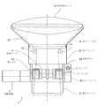
ここで図面を参照すると、図1〜図6に図示される本発明の小型装置は、間隙充填材および緩衝材ダンネージとして使用するための材料を製造および分配するためのものである。装置1は、たとえば図6のフロアスタンド2などの架台部の上に取り付けることができる相対的に小型の一体化した装置である。装置1は駆動装置3と、図6の材料ロール5などの材料の供給から材料を引き出し、装置を通してそれを送るための駆動装置により駆動される材料供給部4、図4を備える。 Referring now to the drawings, the miniature device of the present invention illustrated in FIGS. 1-6 is for manufacturing and dispensing materials for use as gap fillers and cushioning dunnages. The
材料送り装置4は、実施形態の例では用紙である材料8が図5に描かれているようにあいだを送られる協働供給ローラ6と7、図4を参照、を備える。材料供給部4の上流にある複数の材料型削り部材は、材料が装置1を通って送られるにつれて、材料8を緩衝材製品の連続片に成形する。材料形成部材は、供給ローラ6と7によって材料8がその上で引き寄せられる凸状の材料形成ローラ9を含む。凸状ローラ9の下流にある材料8の投入開口部10は、第1組および第2組の離間した平行ローラ11、12および13、14により画定される。第2組のローラ13、14は第1組のローラ11、12の方向を横断する方向で伸張する。材料8が凸状ローラ9の上を引き寄せられると、材料の側面方向の端縁がローラ9の凸状表面の上を第1方向で向けられる。投入開口部10を通る材料9の連続した移動は、緩衝材製品の連続片を形成するために材料の上で端縁が折り返されるように第2の方向で材料8の側面方向の端縁を向ける。さらに具体的には、図7A、7Bおよび7Cに図示されるように、凸状ローラ9および2組のローラ11、12および13、14が、ロール5からの用紙が供給ローラ6と7によって引き出され、用紙を折り畳み、緩衝材ダンネージとして使用するためのピロー状の形状に形成する変換アセンブリを構成する。図7Bのペーパピロー15を参照すること。 The
小型装置1は、材料が装置を通って送られるにつれて材料の条長に沿った離間位置17で用紙材料8を穿孔するために駆動装置3により駆動される穿孔器16をさらに備える。材料の各側の直線穿孔17は、材料がそのあいだを送られる協働穿孔ギア18と19により為される端縁切除である。穿孔ギア18および19は、送られている材料の各側で供給ローラ6と7と同軸で配列される。ピロー状の形をした材料が小型装置1から分配されると、材料の離間した穿孔17のために、操縦者は装置から図7のピロー15のような所望の長さの緩衝材製品を切り取ることができる。 The
装置1の投入シュート20および産出シュート21は、材料供給部4のそれぞれの側で材料8を誘導する。投入シュートおよび産出シュート、凸状の材料形成ローラ9、投入ローラ11、12、および13、14、および装置の他の構成部品は装置の支持体フレーム22に一つの装置として取り付けられる。実施形態の例では、枢動ヘッドの形の小型装置1は、用紙材料の装填を容易にするために多方向枢動のためにフロアスタンド2、図6、に取り付けられている。フロアスタンド2の上の枢動ヘッド1のさまざまな位置は図6の破線で示されている。ローラ組11、12および13、14により画定される投入開口部10のサイズが、操縦者の安全のために操縦者の手が投入開口部を通って差し込まれるのを防ぐほど小さいことが注意される。 The
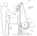
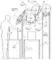
間隙充填材および緩衝材ダンネージとして使用するための材料を製造および分配する本発明のシステム23は、図6に示されている。システムは、小型装置1と、小型装置が取り付けられる架台部2を組み合わせて含む。システム23はさらに、操縦者26が装置1からピロー状に成形された材料15を移動し、出荷される物品が入った箱27の中にそれを差し込むために作業面25を提供する作業台24を備える。図6のシステム23は、さらに、小型装置に供給するために小型装置1の供給ローラ6および7によって引っ張ることにより材料を解くことができる用紙ロール5を回転可能に支えるロール支持体28を備える。図6のシステム23のロール支持体28は、車輪32付きの材料カート31の形を取っている。 A system 23 of the present invention for producing and dispensing material for use as a gap filler and buffer dunnage is shown in FIG. The system includes a combination of a
図8の実施形態の例のシステム33は、材料目録記載ステーション35上で支えられる架台部34を備える。図9のシステム36は、小型装置1が材料目録記載ステーションの下部脚部30上の材料目録記載ステーションの作業面の下に枢止されるという点を除き、図8のシステムに類似している。図10の実施形態の例のシステム38は、作業面40を提供するために小型装置の前に位置しているコンベア39を備えた図6のフロアスタンドのようなフロアスタンド2を利用する。図11のシステム41は、作業面42を材料カート43と統合する。カート43は作業面42の下に小型装置1を枢止する役割も果たす。カート43上の車輪44のためにシステム全体が移動できる。 The
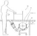
図12の実施形態の例のシステム45は、コンベア47の下に小型装置1を枢支するロールテンショナ67付きの材料カート46を使用する。図13のシステム48は、材料カートがコンベア49の後ろに位置し、小型装置1だけがコンベアの下に位置する点を除き、図12のシステムに類似している。 The
図14のシステム50は、必要に応じて用紙供給を補充するためにロール支持体51に送達するためにバックアップ材料ロール53を供給する躍動供給コンベア52付きの材料ロール5用の高架ロール支持体51を含む。躍動供給コンベア52は、図14に描かれているような送達材料ロール54を提示する。送達材料ロール54は、図14に概略して示される枢動移動アーム55と56によりバックアップ材料ロール53の位置に移送される。図14のシステムの変形は、ロール支持体57がプレテンショナ58を含む図15に図示されている。ロール支持体は、図15のシステム59内のフロアスタンド2および躍動供給コンベア52上に取り付けられている。 The
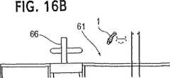
頭上躍動供給コンベア52は、図16Aおよび16Bのシステム60に概略して示され、コンベアは材料ロールを5つの個別包装ステーション61〜65に供給する。包装ステーションのそれぞれには、緩衝材ダンネージを製造し、物品を包装している操縦者、およびワークステーションでのコンテナに分配するための作業面上に支えられる本発明の小型装置1が備えられる。ステーションのうちの一つ、61は、図16Bの側面図に概略して示されている。テープ貼り機は66で示されている。 Overhead
図14と図15の頭上ロール送達システムの動作がここで説明される。第1の工程では、用紙ロールが、ロール移送ゲート55(閉じられている)がロールが移動するのを止めるまで躍動コンベア52上で移動する(進む)。ロールが移動するのを止めると、ロール分配枢動移送アーム56がロールを躍動コンベアの経路から押し出す。ロールが躍動コンベアから押し出された後、ロールは、図15に示されるロール停止/解放アーム70に逆らって停止する。ロールがロール停止/解放アーム70に逆らって留まる限り、ロール移送ゲート55は開いたままとなり、用紙のロールが躍動コンベア上を次に使用可能なステーションまで移動できるようにする。用紙の新しいロールがたとえばステーション61〜65のいずれかの分配装置に必要とされるとき、操縦者はロール停止/解放アーム70を使用して、用紙ロールが図15に図示されるように自動ロールテンション相非58の中に落下できるようにスタンバイロールを解放する。この点で、ロールは使用される用意ができている。ロールが自動ロールテンション装置の中に落下した後、ロール移送ゲート55が閉じる。 The operation of the overhead roll delivery system of FIGS. 14 and 15 will now be described. In the first step, the paper roll moves (advances) on the
実施形態の例では、用紙材料は好ましくは24インチ〜34インチの初期幅を有している。端縁が装置の変換アセンブリによって折り畳まれた後、ピロー形状の製品の幅はたとえば7インチ〜8インチに縮小され、連続片はたとえば7インチごとに片側の17で穿孔される。装置およびダンネージ製品は、言うまでもなく他の大きさの緩衝材製品を製造するための寸法にすることができるだろう。 In the example embodiment, the paper material preferably has an initial width of 24 inches to 34 inches. After the edges are folded by the conversion assembly of the device, the width of the pillow-shaped product is reduced to, for example, 7 inches to 8 inches, and the continuous pieces are perforated at 17 on one side, for example, every 7 inches. The device and dunnage product could of course be dimensioned to produce other sizes of cushioning products.
使用においては、操縦者は用紙が装置1の全面にある分配シュート21から伸張するまで、コントローラ69、図1の供給スイッチ68を押すことによって小型装置1の近隣に位置する供給ロール5から用紙または他の材料を手作業で送る。操縦者は、用紙の分配を開始するために図示されていない足元スイッチを押す。用紙が装置1の内側と通って移動するにつれて、用紙は折り畳まれ、緩衝用ダンネージとして使用するためのピロー状の形に形成される。形成された材料は、実施形態の例の17で7インチごとに片側端縁で均等に穿孔される。所望の長さの緩衝材製品に達すると、操縦者は足元スイッチを放し、緩衝材製品の分配を停止する。操縦者は、所望される穿孔直線で装置から緩衝材製品を切り取り、間隙充填材または緩衝材のために使用するために箱27の中に製品を入れる。 In use, the operator can remove the paper or paper from the
本発明の小型装置およびシステムは、有利なことに、その包装ニーズが、多くの空間を占めない単一の装置で満たすことができるカスタマにとって手頃かつ実用的である。それは、また、61〜65などの複数のスタンドアロン式包装ステーションおよび/または集中包装ステーションが活用される高速生産ラインおよび大量生産ラインを備えるカスタマのニーズにも柔軟に応えることができる。作業台の上または下に、およびコンベアラインの上または下に設置できる高い柔軟性の設置構成オプションが複数の実施形態の例に図示されている。架台部/材料カート上での装置1の多方向枢動は、装置1内に用紙材料8を装填するのを容易にするためである。穿孔は現場で、リアルタイムで用紙材料に達成されるため、事前に穿孔された用紙をロールに提供する必要はない。 The miniature device and system of the present invention is advantageously affordable and practical for customers whose packaging needs can be met with a single device that does not occupy much space. It can also flexibly meet the needs of customers with high-speed production lines and mass production lines where multiple stand-alone packaging stations such as 61-65 and / or centralized packaging stations are utilized. Highly flexible installation configuration options that can be installed above or below the workbench and above or below the conveyor line are illustrated in the example embodiments. The multi-directional pivoting of the
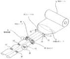
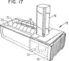
本発明の小型装置71の他の実施形態が、部分的に図17〜20Dに示されている。装置71は図1〜5に示されたものと類似し、図6および8〜16Bのシステムにおいて使用可能であって、小型装置1で穿孔ギア18および19を使用する代わりに、少なくともそのうちの一つは回転切削ダイである協働供給ローラ72および73からなる点で相違する。実施形態の例において供給ローラのうちの一つ72のみが、材料が装置を通って供給されると、材料の条長に沿った離間位置で材料にスリット86を入れるための複数の刃物74を有する回転切削ダイであり、それによって操縦者が装置から分配される緩衝材を所望の長さに装置から切り取る、図20Dに概略的に示される材料から切り取られる長さ75を参照。 Another embodiment of the
実施形態の例の供給ローラ73は滑らかな環状の面を有するため、ローラの間に供給されローラ72の刃物74によって切りこみを入れられる材料の金床として作用する。ローラは制御装置78の制御のもとで伝動装置77を通じて駆動装置76によって駆動され、その操作は図1〜5の実施の形態および図6および図8〜16Bのシステムに記載されたものに類似する。図1〜5記載の投入ローラ11〜14および材料形成ローラ9は、簡潔に記載するために図17〜20Dにおいては記載されていないが、小型装置71においても使用されている。 The
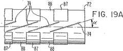
図17の回転切削ダイアセンブリ79は、装置71の両口式シュート構造80に装置のどちら側からでも図18に示されている矢印A方向に脱着可能に取り付けられている装置である。構造80は各々の開口部83および84を通って小型装置の協働供給ローラへ導き導かれる、投入および産出シュート81および82をそれぞれ形成する。回転切削ダイ/供給ローラ72上の刃74は、図19Aに示されるようにローラ軸B−Bに対し角度αに配置される。実施形態の例において角度αは18°であるが他の角度でもよい。しかしながら以下に記載される理由により、好ましくは10°〜80°の範囲内である。図19Bおよび19Cに示されるように、刃は外側の刃の部分がローラの表面から突出しローラの周囲に沿うようにしてローラの表面に埋め込まれる。実施形態の例に示される滑らかな表面の供給ローラ73は、超高分子プラスチックから形成される。ローラは均一の摩耗のため、ローラ72とはわずかに異なる直径を有している。ローラ72および73の間に供給される材料8は、材料を供給し片にスリットを入れるための回転駆動ローラの対向する面の間に挟まれる。 The rotary cutting die
回転切削ダイアセンブリ79の上流の複数の形成ローラは、材料の幅を減縮するためになるべく寸法を合わせて調節されることにより、不規則な重畳85が材料の幅にわたり形成される。これは図7A〜7Cの製品のように材料の縁を折りたたむことなくなされるものである。ローラは材料の接触片と共に移動するように回転可能に取り付けられ、それによって滑り接触および摩擦を減少させることができる。これらの重畳を含む材料は、回転切削ダイによってスリットが入れられる。この特徴は、材料の重畳部分に切り込まれるスリット86の角度と共に、材料の分離が紙または他の材料の不規則な重畳を、図20Bおよび20Cに参照される不規則なハチの巣型構造86に変えることによってスリットを拡張することにより始まる。材料の分離は、操縦者が切り離すことにより図20Dの材料の長さ75を供給するためのハチの巣型構造を分割をもって完了する。 The plurality of forming rollers upstream of the rotary cutting
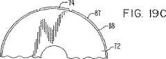
実施形態の例の供給ローラ/回転切削ダイ72は、ローラ軸B−Bに沿って離間された相対的に大きいまた相対的に小さい直径の環状部87および88をともなう周囲面を有する。図19Aに示される刃物74は、ローラの軸端部中央部で相対的に大きな直径の環状部87の対向端の間に位置している。小型装置71により製造される充填材および緩衝ダンネージは、装置より供給される際に条長に沿っている各々の切込み部分において調節効果を有用に示し、それによって図20A〜20Cの87に示されるように材料が分配される間に容易に重なって折りたたまれる。これにより、一度充填操作が始まると操縦者の努力をほとんど必要とせずに早くパッケージの間隙を充填することができることが明らかになった。スリットはまた、一度パッケージが充填されると連続する片から材料の長さを素早く切り取ることを可能にするものである。 The example feed roller / rotary cutting die 72 has a peripheral surface with relatively large and relatively small diameter
私は本発明による複数の実施形態の例だけを示し、説明したが、多様な変更および変型が本発明から逸脱することなく当業者によってそこに加えることができることが理解される。したがって、私はここに開示される特定の実施形態の例に制限されることを好まないが、添付請求項の範囲によって含まれるようなこのような変型をカバーすることを意図する。 I have shown and described only a plurality of example embodiments according to the present invention, but it is understood that various changes and modifications may be made thereto by those skilled in the art without departing from the present invention. Accordingly, I do not like to be limited to the specific embodiment examples disclosed herein, but are intended to cover such variations as encompassed by the scope of the appended claims.
Claims (39)
Translated fromJapanese駆動装置と、前記駆動装置によって駆動される材料供給部からなり、前記材料供給部が材料の供給から材料を引き出し前記装置を通して供給するための、対向する連続的な円周の円筒状の面を有する協働供給ローラを含み;
材料が前記装置を通り供給されるにつれ、前記材料の縁を折りたたむことなく、不規則な条長に伸張する重畳が材料の幅に渡って形成されるように材料の幅を減少させる前記材料供給部の上流にある複数の材料形成部材からなり;および
分配されるあいだ材料が容易に重なって折りたたまれること、および前記装置から分配される緩衝材を操縦者が所望の長さに切りとることを可能にするために、材料が前記装置を通り供給されるにつれ、前記材料の条長に沿った離間位置で重畳を含む材料にスリットを入れるための、ローラ軸に対して鋭角に配置される複数の刃物を表面に有する少なくとも一つは回転切削ダイである供給ローラからなることを特徴とする小型装置。A small device capable of being mounted on a cradle for producing and distributing material for use as a gap filler and buffer dunnage,
A driving device and a material supply unit driven by the driving device, wherein the material supply unit draws the material from the material supply and supplies the material through the device with opposing continuous circumferential cylindrical surfaces Including a cooperating supply roller having;
As the material is fed through the device, the material supply reduces the width of the material so that an overlap that extends toan irregular length is formed across the width of the materialwithout folding the edges of the material Consisting of a plurality of material forming members upstream of the section; and allows material to easily overlap and fold while dispensed, and allow the operator to cut the cushion dispensed from the device to the desired length As the material is fed through the apparatus, a plurality of materials arranged at an acute angle with respect to the roller axis for slitting the material including overlap at spaced locations along the length of the material. A small apparatus characterized in that at least one having a blade on its surface is a supply roller which is a rotary cutting die.
駆動装置と、前記駆動装置によって駆動される材料供給部からなり、前記材料供給部が材料の供給から材料を引き出してアセンブリを通して供給するために、材料がそのあいだに挟まれる対向する連続的な円周の円筒状の面を有する協働供給ローラを含み;
材料がアセンブリを通り供給されるにつれ、前記材料の縁を折りたたむことなく、前記材料の条長に沿った離間位置で材料にスリットを入れるための、ローラ軸に対して鋭角に配置される複数の刃物を表面に有する、少なくとも一つは回転切削ダイである供給ローラからなることを特徴とするアセンブリ。A die cutting assembly for use in an apparatus for manufacturing and dispensing material for use as a gap filler and cushion dunnage, said assembly comprising:
An opposing continuous circle between which material is sandwiched between a drive and a material supply driven by the drive for the material supply to draw material from the supply of material and supply it through the assembly A cooperating supply roller having a circumferential cylindrical surface;
As the material is fed through the assembly, a plurality of arranged at acute angles to the roller axis to slit the material at spaced locations along the length of the materialwithout folding the edges of the material. An assembly comprising a supply roller having a cutting tool on the surface, at least one of which is a rotary cutting die.
材料の供給から材料を引き出す工程と;
材料の縁を折りたたむことなく材料の幅に渡って条長に伸張する複数の重畳を形成するために、引き出された材料の幅を減少するように形成する工程と;
不規則な重畳を含む材料に、回転切削ダイにより前記材料の条長に沿った離間位置に複数のスリットを入れることによって、引き出された材料を緩衝材の連続片に変換する工程からなる方法。A method for producing and dispensing a material for use as a gap filler and buffer dunnage comprising:
Withdrawing material from the material supply;
To form a plurality of superimposed extending the fiber length across the width of the materialwithout fold folding theedges of the material to form so as to reduce the width of the drawn material;
A method comprising the step of converting a drawn material into a continuous piece of cushioning material by inserting a plurality of slits at spaced positions along the length of the material with a rotary cutting die into the material containing irregular overlap.
駆動装置と、前記駆動装置によって駆動される材料供給部とを含み、前記材料供給部が、材料の供給から材料を引き出して材料を前記装置を通して供給するための、対向する連続的な円周の円筒状の面を有する協働供給ローラと;
材料が前記装置を通って送られるにつれて、材料を緩衝材製品の連続片に変換するために材料を形成する前記材料供給部の上流にある複数の材料形成部材と;
前記装置から分配される緩衝材を操縦者が所望の長さに切り取ることを可能にするために、材料が前記装置を通って供給されるにつれ、前記材料の縁を折りたたむことなく、前記材料の条長に沿った離間位置で材料スリットを入れるための、表面がローラ軸に対して鋭角に配置される複数の刃物を表面に有する回転切削ダイである少なくとも一つの供給ローラからなることを特徴とするシステム。A system for manufacturing and distributing materials for use as gap filler and buffer dunnage, wherein the system is a pedestal and a small device mounted as a device on the cradle, the small device comprising A drive device and a material supply driven by the drive device, wherein the material supply portion draws material from the material supply and supplies the material through the device with opposing continuous circumferences A cooperating supply roller having a cylindrical surface;
A plurality of material forming members upstream of the material supply that forms the material to convert the material into a continuous piece of cushioning product as the material is fed through the device;
To allow the operator to cut the buffer dispensed from the device to the desired length, as the material is fed through the device, thematerial's edges can be folded without folding . It is characterized by comprising at least one supply roller which is a rotary cutting die having a plurality of blades on the surface, the surface of which is arranged at an acute angle with respect to the roller axis, for inserting material slits at spaced positions along the strip length. System.
架台部および架台部の上に1つの装置として取り付け可能な小型装置であって、前記小型装置が
駆動装置と、材料の供給から材料を引き出し前記装置を通して材料を送るための、前記駆動装置により駆動される材料供給部と、
材料が前記装置を通って送られるにつれて、材料を緩衝材製品の連続片に変換するために材料を形成する前記材料供給部の上流にある複数の材料形成部材とを含み、
前記材料供給部が、対向する連続的な円周の円筒状の面を有する協働供給ローラを含み、少なくとも一つの前記供給ローラが、前記装置から分配される緩衝材を操縦者が所望の長さに切りとることを可能にするために、材料が前記装置を通って供給されるにつれ、前記材料の縁を折りたたむことなく、前記材料の条長に沿った離間位置で材料にスリットを入れるための、ローラ軸に対して鋭角に配置される複数の刃物を表面に有する回転切削ダイであって;前記システムがさらに
前記小型装置に供給され解かれる材料のロールを、回転可能に支えるためのロール支持体を含むことを特徴とするシステム。A system for producing and dispensing material for use as a gap filler and buffer dunnage comprising:
A small device that can be mounted as a single device on a pedestal and a pedestal portion, wherein the small device is driven by the drive device and the drive device for extracting material from the supply of material and feeding the material through the device A material supply unit,
As the material is fed through said apparatus, anda plurality of materials forming member upstream of the material supply portion for forming the material to convert the material into a continuous strip of cushioning material product,
The material supply section includes cooperating supply rollers having opposing continuous circumferential cylindrical surfaces, wherein at least one of the supply rollers has a desired length of cushioning material dispensed from the device. To allow the material to be slit at spaced locations along the length of the material,without folding the edges of the material, as thematerial is fed through the device. A rotary cutting die having on its surface a plurality of blades arranged at an acute angle with respect to the roller axis; roll support for rotatably supporting a roll of material that is further fed to and unwound by the system A system characterized by including a body.
Applications Claiming Priority (2)
| Application Number | Priority Date | Filing Date | Title |
|---|---|---|---|
| US10/208,772US6673001B2 (en) | 2001-03-29 | 2002-08-01 | Compact apparatus and system for creating and dispensing cushioning dunnage |
| PCT/US2003/023738WO2004012930A1 (en) | 2002-08-01 | 2003-07-31 | Compact apparatus and system for creating and dispensing cushioning dunnage |
Publications (2)
| Publication Number | Publication Date |
|---|---|
| JP2005534539A JP2005534539A (en) | 2005-11-17 |
| JP4578239B2true JP4578239B2 (en) | 2010-11-10 |
Family
ID=31494262
Family Applications (1)
| Application Number | Title | Priority Date | Filing Date |
|---|---|---|---|
| JP2004526212AExpired - Fee RelatedJP4578239B2 (en) | 2002-08-01 | 2003-07-31 | Compact apparatus and method for manufacturing and dispensing cushioning materials |
Country Status (6)
| Country | Link |
|---|---|
| US (3) | US6673001B2 (en) |
| EP (1) | EP1539475A4 (en) |
| JP (1) | JP4578239B2 (en) |
| AU (1) | AU2003257004A1 (en) |
| CA (1) | CA2494020C (en) |
| WO (1) | WO2004012930A1 (en) |
Families Citing this family (47)
| Publication number | Priority date | Publication date | Assignee | Title |
|---|---|---|---|---|
| US7172548B2 (en)* | 2001-03-29 | 2007-02-06 | Zsolt Design Engineering, Inc. | Cushioning conversion system and method |
| US6910997B1 (en) | 2004-03-26 | 2005-06-28 | Free-Flow Packaging International, Inc. | Machine and method for making paper dunnage |
| US20060199719A1 (en)* | 2005-03-02 | 2006-09-07 | White Thornton C | Roll stand paper guide |
| BRPI0608477A2 (en)* | 2005-03-12 | 2010-01-05 | Sealed Air Corp | inflatable containers |
| BRPI0615718A2 (en)* | 2005-09-12 | 2011-05-24 | Sealed Air Corp | flexible valves |
| US20070117703A1 (en)* | 2005-11-22 | 2007-05-24 | Sealed Air Corporation | Machine and method for converting a web of material into dunnage |
| FR2898542B1 (en)* | 2006-03-14 | 2008-05-30 | Michelin Soc Tech | VEHICLE COMPRISING AT LEAST ONE MOUNTED ASSEMBLY AND USE OF A MEASUREMENT SYSTEM |
| DE102006054593A1 (en)* | 2006-11-20 | 2008-05-21 | Pack-Tiger Gmbh | Machine for producing paper upholstery |
| EP2203304B1 (en) | 2007-09-24 | 2015-05-13 | Ranpak Corp. | Dunnage conversion machine and method |
| WO2010129560A1 (en)* | 2009-05-04 | 2010-11-11 | Ranpak Corp. | Drop and slide mechanism for use with dunnage conversion machine and method |
| US8641591B2 (en) | 2010-08-26 | 2014-02-04 | Pregis Innovative Packaging, Inc. | Center-fed dunnage system |
| US8554363B2 (en) | 2010-09-21 | 2013-10-08 | Sealed Air Corporation | Apparatus configured to dispense a plurality of connected inflatable structures and associated system and method |
| EP2655053B1 (en) | 2010-12-23 | 2017-03-22 | Pregis Innovative Packaging LLC | Center-fed dunnage system feed and cutter |
| EP3292966B1 (en) | 2011-09-20 | 2021-05-05 | Pregis Innovative Packaging LLC | Tear-assist apparatus |
| EP2776221B1 (en) | 2011-11-10 | 2016-07-13 | Packsize LLC | Converting machine |
| DE102012018941A1 (en)* | 2012-09-25 | 2014-03-27 | Sprick Gmbh Bielefelder Papier- Und Wellpappenwerke & Co. | A machined packaging product, method and apparatus for machining the packaging product |
| DE102012218681A1 (en)* | 2012-10-12 | 2014-04-17 | Storopack Hans Reichenecker Gmbh | Apparatus for producing a padding product from paper |
| DE102012218679A1 (en)* | 2012-10-12 | 2014-04-17 | Storopack Hans Reichenecker Gmbh | Device for producing a cushion of paper |
| DE102013015875A1 (en)* | 2013-09-23 | 2015-03-26 | Sprick Gmbh Bielefelder Papier- Und Wellpappenwerke & Co. | Perforating tool for a device for machining a filler product and apparatus for machining a filler product |
| US9475666B2 (en) | 2013-11-04 | 2016-10-25 | Kucharco Corporation | Full contact teter dispension for controlling deployment of expandable web material |
| WO2015103251A1 (en)* | 2013-12-31 | 2015-07-09 | Ranpak Corp. | Universal feedstock of strand packing material with cohesive |
| US20150352802A1 (en)* | 2014-06-09 | 2015-12-10 | Storopack, Inc. | Protective packaging work station |
| WO2016044767A1 (en)* | 2014-09-19 | 2016-03-24 | Chan Simon Cs | Dunnage system |
| US10093438B2 (en) | 2014-12-29 | 2018-10-09 | Packsize Llc | Converting machine |
| JP6625731B2 (en)* | 2015-08-31 | 2019-12-25 | ランパック コーポレイション | Loading conversion machine |
| US11858232B1 (en)* | 2016-03-28 | 2024-01-02 | Intertape Polymer Corp. | Modular dunnage machine |
| US10850469B2 (en) | 2016-06-16 | 2020-12-01 | Packsize Llc | Box forming machine |
| WO2017218296A1 (en)* | 2016-06-16 | 2017-12-21 | Packsize Llc | A box template production system and method |
| US11242214B2 (en) | 2017-01-18 | 2022-02-08 | Packsize Llc | Converting machine with fold sensing mechanism |
| SE541921C2 (en) | 2017-03-06 | 2020-01-07 | Packsize Llc | A box erecting method and system |
| DE102017109829A1 (en)* | 2017-05-08 | 2018-11-08 | Sprick Gmbh Bielefelder Papier- Und Wellpappenwerke & Co. | Device for providing packaging material |
| US10926506B2 (en) | 2017-05-11 | 2021-02-23 | Pregis Innovative Packaging Llc | Fanfold supply cart |
| US11020930B2 (en) | 2017-05-11 | 2021-06-01 | Pregis Innovative Packaging Llc | Splice member on stock material units for a dunnage conversion machine |
| US10940659B2 (en) | 2017-05-11 | 2021-03-09 | Pregis Innovative Packaging Llc | Strap assembly on stock material units for a dunnage conversion machine |
| US11034121B2 (en)* | 2017-05-11 | 2021-06-15 | Pregis Innovative Packaging Llc | Dunnage apparatus carton filler |
| US11007746B2 (en) | 2017-05-11 | 2021-05-18 | Pregis Innovative Packaging Llc | Dunnage supply intake |
| SE1750727A1 (en) | 2017-06-08 | 2018-10-09 | Packsize Llc | Tool head positioning mechanism for a converting machine, and method for positioning a plurality of tool heads in a converting machine |
| US20190105865A1 (en)* | 2017-10-11 | 2019-04-11 | Adam Kelley | Machine for converting spooled material into dunnage |
| US11173685B2 (en) | 2017-12-18 | 2021-11-16 | Packsize Llc | Method for erecting boxes |
| US11305903B2 (en) | 2018-04-05 | 2022-04-19 | Avercon BVBA | Box template folding process and mechanisms |
| US11247427B2 (en) | 2018-04-05 | 2022-02-15 | Avercon BVBA | Packaging machine infeed, separation, and creasing mechanisms |
| DE112019003075T5 (en) | 2018-06-21 | 2021-03-25 | Packsize Llc | PACKAGING DEVICE AND SYSTEMS |
| SE543046C2 (en) | 2018-09-05 | 2020-09-29 | Packsize Llc | A box erecting method and system |
| DE112020000348T5 (en) | 2019-01-07 | 2021-09-16 | Packsize Llc | Carton erecting machine |
| US11607531B2 (en) | 2019-05-09 | 2023-03-21 | Neuravi Limited | Balloon catheter with venting of residual air in a proximal direction |
| US12179454B2 (en) | 2020-11-13 | 2024-12-31 | Ranpak Corp. | Dunnage conversion machine and method with assisted tear apparatus |
| EP4547477A2 (en)* | 2022-07-01 | 2025-05-07 | Pregis Llc | Dunnage systems with automated feeding capability |
Family Cites Families (33)
| Publication number | Priority date | Publication date | Assignee | Title |
|---|---|---|---|---|
| US673312A (en)* | 1900-05-01 | 1901-04-30 | Duplex Printing Press Co | Paper-folding machine. |
| US803972A (en)* | 1905-02-11 | 1905-11-07 | Duplex Printing Press Co | Web-feeding rolls. |
| US1739328A (en)* | 1927-12-14 | 1929-12-10 | Wood Newspaper Mach Corp | Folding machine for tabloid newspapers |
| US2786399A (en) | 1952-03-06 | 1957-03-26 | Veyne V Mason | Formation of crumpled sheet material filter elements and the like |
| US3473291A (en)* | 1967-05-18 | 1969-10-21 | G R Kirk Co | Sheathing apparatus |
| US3522762A (en)* | 1968-08-12 | 1970-08-04 | Louis E Sauer | Multiple anvil structure for rotary die cutting |
| US3613528A (en)* | 1969-09-15 | 1971-10-19 | Revco Inc | Belt rotary diecutter |
| US3603216A (en) | 1970-02-09 | 1971-09-07 | Arpax Co | Method for producing cushioning dunnage |
| US3799039A (en) | 1971-12-14 | 1974-03-26 | Ranpak Corp | Cushioning dunnage mechanism and method |
| DE2637090A1 (en) | 1975-09-01 | 1977-04-21 | Paclene Co Ltd | MACHINE FOR PERFORATING HIGH DENSITY POLYAETHYLENE FILM |
| US4355493A (en)* | 1980-06-17 | 1982-10-26 | Scholle Corporation | Roller chute |
| JPS6038142A (en)* | 1983-08-10 | 1985-02-27 | 三和レジン工業株式会社 | Manufacture of double layer bag |
| US4750896A (en) | 1985-10-28 | 1988-06-14 | Ranpak Corp. | Method and mechanism for producing cushioning dunnage product |
| US4999968A (en) | 1990-01-02 | 1991-03-19 | W. A. Lane, Inc. | Packaging machine pouch perforator |
| US5076555A (en) | 1990-07-25 | 1991-12-31 | Bunch Jr Earnest B | Apparatus for partially severing strip of paper along lines offset from lines of weakening in the paper |
| US5131903A (en) | 1991-03-25 | 1992-07-21 | Sanford Levine And Sons Packaging Corp. | Apparatus for crumpling and dispensing paper-like dunnage |
| US5203761A (en) | 1991-06-17 | 1993-04-20 | Sealed Air Corporation | Apparatus for fabricating dunnage material from continuous web material |
| US5681255A (en) | 1993-05-21 | 1997-10-28 | Ranpak Corp. | Dispensing table and guide system for a cushioning conversion machine |
| US5791483A (en) | 1994-04-01 | 1998-08-11 | Ranpak Corp. | Cushioning product |
| US5755656A (en) | 1995-06-07 | 1998-05-26 | Ranpak Corp. | Cushioning conversion machine and method with independent edge connecting |
| US5938580A (en) | 1994-04-15 | 1999-08-17 | Ranpak Corp. | Cushioning conversion machine with restricted access to a cutting assembly |
| US5749539A (en) | 1994-06-29 | 1998-05-12 | Ranpak Corp. | Dunnage-creating machine with plugless paper roll and method |
| US6217501B1 (en) | 1996-06-28 | 2001-04-17 | Ranpak Corp. | Cushioning conversion machine |
| US5730696A (en) | 1995-06-07 | 1998-03-24 | Ranpak Corp. | Cushioning conversion machine selectively pivotable in a horizontal plane |
| US5902223A (en) | 1995-10-06 | 1999-05-11 | Ranpak Corp. | Cushoning conversion machine |
| US5643647A (en) | 1996-06-12 | 1997-07-01 | Rock-Tenn Company | Loose fill dunnage elements of paperboard or the like |
| EP0921937B1 (en) | 1996-07-26 | 2000-10-11 | Ranpak Corp. | Cushioning conversion system |
| US6033353A (en) | 1997-02-26 | 2000-03-07 | Ranpak Corp. | Machine and method for making a perforated dunnage product |
| WO1998040204A1 (en)* | 1997-03-11 | 1998-09-17 | Ranpak Corp. | Cushioning conversion machine and method |
| DE69940790D1 (en) | 1998-01-12 | 2009-06-04 | Ranpak Corp | Cushioning conversion machine |
| US6179765B1 (en) | 1998-10-30 | 2001-01-30 | Ft Acquisition, L.P. | Paper dispensing system and method |
| US6277459B1 (en) | 1999-01-19 | 2001-08-21 | Ranpak Corp. | Perforated cushioning dunnage product, machine and method for making same |
| EP1311384B1 (en)* | 2000-08-24 | 2006-11-15 | Ranpak Corp. | Dunnage conversion machine, method and dunnage product |
- 2002
- 2002-08-01USUS10/208,772patent/US6673001B2/ennot_activeExpired - Lifetime
- 2003
- 2003-07-31CACA2494020Apatent/CA2494020C/ennot_activeExpired - Fee Related
- 2003-07-31EPEP03766966Apatent/EP1539475A4/ennot_activeWithdrawn
- 2003-07-31WOPCT/US2003/023738patent/WO2004012930A1/enactiveApplication Filing
- 2003-07-31AUAU2003257004Apatent/AU2003257004A1/ennot_activeAbandoned
- 2003-07-31JPJP2004526212Apatent/JP4578239B2/ennot_activeExpired - Fee Related
- 2003-08-26USUS10/647,252patent/US7163503B2/ennot_activeExpired - Lifetime
- 2006
- 2006-12-19USUS11/640,846patent/US7347809B2/ennot_activeExpired - Lifetime
Also Published As
| Publication number | Publication date |
|---|---|
| EP1539475A4 (en) | 2011-02-02 |
| JP2005534539A (en) | 2005-11-17 |
| US20020193224A1 (en) | 2002-12-19 |
| US6673001B2 (en) | 2004-01-06 |
| EP1539475A1 (en) | 2005-06-15 |
| WO2004012930A1 (en) | 2004-02-12 |
| US20040043883A1 (en) | 2004-03-04 |
| CA2494020A1 (en) | 2004-02-12 |
| US7347809B2 (en) | 2008-03-25 |
| CA2494020C (en) | 2013-11-19 |
| AU2003257004A1 (en) | 2004-02-23 |
| US20070117704A1 (en) | 2007-05-24 |
| US7163503B2 (en) | 2007-01-16 |
Similar Documents
| Publication | Publication Date | Title |
|---|---|---|
| JP4578239B2 (en) | Compact apparatus and method for manufacturing and dispensing cushioning materials | |
| US7479100B2 (en) | Cushioning conversion system and method | |
| US7335151B2 (en) | Method, apparatus and system for making cushioning product, and roll tensioner therefor | |
| CN107257733B (en) | Dunnage conversion system and method for expanding pre-slit sheet stock material | |
| JP4285999B2 (en) | Compact device and system for creating and distributing cushioning dunnage | |
| JP6895535B2 (en) | Dunnage converter with variable spacing for stretchable slit sheet stock material | |
| US6436511B1 (en) | Cushioning conversion machine, method and product | |
| AU2002244237A1 (en) | Compact apparatus and system for creating and dispensing cushioning dunnage |
Legal Events
| Date | Code | Title | Description |
|---|---|---|---|
| A621 | Written request for application examination | Free format text:JAPANESE INTERMEDIATE CODE: A621 Effective date:20060630 | |
| A131 | Notification of reasons for refusal | Free format text:JAPANESE INTERMEDIATE CODE: A131 Effective date:20090602 | |
| A02 | Decision of refusal | Free format text:JAPANESE INTERMEDIATE CODE: A02 Effective date:20100202 | |
| A521 | Request for written amendment filed | Free format text:JAPANESE INTERMEDIATE CODE: A523 Effective date:20100602 | |
| A911 | Transfer to examiner for re-examination before appeal (zenchi) | Free format text:JAPANESE INTERMEDIATE CODE: A911 Effective date:20100716 | |
| TRDD | Decision of grant or rejection written | ||
| A01 | Written decision to grant a patent or to grant a registration (utility model) | Free format text:JAPANESE INTERMEDIATE CODE: A01 Effective date:20100803 | |
| A01 | Written decision to grant a patent or to grant a registration (utility model) | Free format text:JAPANESE INTERMEDIATE CODE: A01 | |
| A61 | First payment of annual fees (during grant procedure) | Free format text:JAPANESE INTERMEDIATE CODE: A61 Effective date:20100824 | |
| FPAY | Renewal fee payment (event date is renewal date of database) | Free format text:PAYMENT UNTIL: 20130903 Year of fee payment:3 | |
| R150 | Certificate of patent or registration of utility model | Ref document number:4578239 Country of ref document:JP Free format text:JAPANESE INTERMEDIATE CODE: R150 Free format text:JAPANESE INTERMEDIATE CODE: R150 | |
| R250 | Receipt of annual fees | Free format text:JAPANESE INTERMEDIATE CODE: R250 | |
| R250 | Receipt of annual fees | Free format text:JAPANESE INTERMEDIATE CODE: R250 | |
| R250 | Receipt of annual fees | Free format text:JAPANESE INTERMEDIATE CODE: R250 | |
| R250 | Receipt of annual fees | Free format text:JAPANESE INTERMEDIATE CODE: R250 | |
| R250 | Receipt of annual fees | Free format text:JAPANESE INTERMEDIATE CODE: R250 | |
| R250 | Receipt of annual fees | Free format text:JAPANESE INTERMEDIATE CODE: R250 | |
| R250 | Receipt of annual fees | Free format text:JAPANESE INTERMEDIATE CODE: R250 | |
| LAPS | Cancellation because of no payment of annual fees |