JP4576002B2 - Portable coordinate measuring device with built-in line laser scanner - Google Patents
Portable coordinate measuring device with built-in line laser scannerDownload PDFInfo
- Publication number
- JP4576002B2 JP4576002B2JP2003568352AJP2003568352AJP4576002B2JP 4576002 B2JP4576002 B2JP 4576002B2JP 2003568352 AJP2003568352 AJP 2003568352AJP 2003568352 AJP2003568352 AJP 2003568352AJP 4576002 B2JP4576002 B2JP 4576002B2
- Authority
- JP
- Japan
- Prior art keywords
- cmm
- probe
- laser scanner
- joint
- housing
- Prior art date
- Legal status (The legal status is an assumption and is not a legal conclusion. Google has not performed a legal analysis and makes no representation as to the accuracy of the status listed.)
- Expired - Fee Related
Links
Images


Classifications
- G—PHYSICS
- G01—MEASURING; TESTING
- G01B—MEASURING LENGTH, THICKNESS OR SIMILAR LINEAR DIMENSIONS; MEASURING ANGLES; MEASURING AREAS; MEASURING IRREGULARITIES OF SURFACES OR CONTOURS
- G01B11/00—Measuring arrangements characterised by the use of optical techniques
- G01B11/24—Measuring arrangements characterised by the use of optical techniques for measuring contours or curvatures
- G01B11/25—Measuring arrangements characterised by the use of optical techniques for measuring contours or curvatures by projecting a pattern, e.g. one or more lines, moiré fringes on the object
- B—PERFORMING OPERATIONS; TRANSPORTING
- B23—MACHINE TOOLS; METAL-WORKING NOT OTHERWISE PROVIDED FOR
- B23Q—DETAILS, COMPONENTS, OR ACCESSORIES FOR MACHINE TOOLS, e.g. ARRANGEMENTS FOR COPYING OR CONTROLLING; MACHINE TOOLS IN GENERAL CHARACTERISED BY THE CONSTRUCTION OF PARTICULAR DETAILS OR COMPONENTS; COMBINATIONS OR ASSOCIATIONS OF METAL-WORKING MACHINES, NOT DIRECTED TO A PARTICULAR RESULT
- B23Q35/00—Control systems or devices for copying directly from a pattern or a master model; Devices for use in copying manually
- B23Q35/04—Control systems or devices for copying directly from a pattern or a master model; Devices for use in copying manually using a feeler or the like travelling along the outline of the pattern, model or drawing; Feelers, patterns, or models therefor
- B—PERFORMING OPERATIONS; TRANSPORTING
- B25—HAND TOOLS; PORTABLE POWER-DRIVEN TOOLS; MANIPULATORS
- B25J—MANIPULATORS; CHAMBERS PROVIDED WITH MANIPULATION DEVICES
- B25J17/00—Joints
- B25J17/02—Wrist joints
- B25J17/0241—One-dimensional joints
- B25J17/025—One-dimensional joints mounted in series
- B—PERFORMING OPERATIONS; TRANSPORTING
- B25—HAND TOOLS; PORTABLE POWER-DRIVEN TOOLS; MANIPULATORS
- B25J—MANIPULATORS; CHAMBERS PROVIDED WITH MANIPULATION DEVICES
- B25J19/00—Accessories fitted to manipulators, e.g. for monitoring, for viewing; Safety devices combined with or specially adapted for use in connection with manipulators
- B25J19/0008—Balancing devices
- B25J19/0016—Balancing devices using springs
- B—PERFORMING OPERATIONS; TRANSPORTING
- B25—HAND TOOLS; PORTABLE POWER-DRIVEN TOOLS; MANIPULATORS
- B25J—MANIPULATORS; CHAMBERS PROVIDED WITH MANIPULATION DEVICES
- B25J19/00—Accessories fitted to manipulators, e.g. for monitoring, for viewing; Safety devices combined with or specially adapted for use in connection with manipulators
- B25J19/0091—Shock absorbers
- B—PERFORMING OPERATIONS; TRANSPORTING
- B25—HAND TOOLS; PORTABLE POWER-DRIVEN TOOLS; MANIPULATORS
- B25J—MANIPULATORS; CHAMBERS PROVIDED WITH MANIPULATION DEVICES
- B25J9/00—Programme-controlled manipulators
- B25J9/0009—Constructional details, e.g. manipulator supports, bases
- B25J9/0012—Constructional details, e.g. manipulator supports, bases making use of synthetic construction materials, e.g. plastics, composites
- B—PERFORMING OPERATIONS; TRANSPORTING
- B25—HAND TOOLS; PORTABLE POWER-DRIVEN TOOLS; MANIPULATORS
- B25J—MANIPULATORS; CHAMBERS PROVIDED WITH MANIPULATION DEVICES
- B25J9/00—Programme-controlled manipulators
- B25J9/02—Programme-controlled manipulators characterised by movement of the arms, e.g. cartesian coordinate type
- B25J9/023—Cartesian coordinate type
- B—PERFORMING OPERATIONS; TRANSPORTING
- B25—HAND TOOLS; PORTABLE POWER-DRIVEN TOOLS; MANIPULATORS
- B25J—MANIPULATORS; CHAMBERS PROVIDED WITH MANIPULATION DEVICES
- B25J9/00—Programme-controlled manipulators
- B25J9/06—Programme-controlled manipulators characterised by multi-articulated arms
- B—PERFORMING OPERATIONS; TRANSPORTING
- B25—HAND TOOLS; PORTABLE POWER-DRIVEN TOOLS; MANIPULATORS
- B25J—MANIPULATORS; CHAMBERS PROVIDED WITH MANIPULATION DEVICES
- B25J9/00—Programme-controlled manipulators
- B25J9/16—Programme controls
- B25J9/1602—Programme controls characterised by the control system, structure, architecture
- G—PHYSICS
- G01—MEASURING; TESTING
- G01B—MEASURING LENGTH, THICKNESS OR SIMILAR LINEAR DIMENSIONS; MEASURING ANGLES; MEASURING AREAS; MEASURING IRREGULARITIES OF SURFACES OR CONTOURS
- G01B11/00—Measuring arrangements characterised by the use of optical techniques
- G01B11/002—Measuring arrangements characterised by the use of optical techniques for measuring two or more coordinates
- G01B11/005—Measuring arrangements characterised by the use of optical techniques for measuring two or more coordinates coordinate measuring machines
- G—PHYSICS
- G01—MEASURING; TESTING
- G01B—MEASURING LENGTH, THICKNESS OR SIMILAR LINEAR DIMENSIONS; MEASURING ANGLES; MEASURING AREAS; MEASURING IRREGULARITIES OF SURFACES OR CONTOURS
- G01B11/00—Measuring arrangements characterised by the use of optical techniques
- G01B11/02—Measuring arrangements characterised by the use of optical techniques for measuring length, width or thickness
- G01B11/03—Measuring arrangements characterised by the use of optical techniques for measuring length, width or thickness by measuring coordinates of points
- G—PHYSICS
- G01—MEASURING; TESTING
- G01B—MEASURING LENGTH, THICKNESS OR SIMILAR LINEAR DIMENSIONS; MEASURING ANGLES; MEASURING AREAS; MEASURING IRREGULARITIES OF SURFACES OR CONTOURS
- G01B21/00—Measuring arrangements or details thereof, where the measuring technique is not covered by the other groups of this subclass, unspecified or not relevant
- G01B21/02—Measuring arrangements or details thereof, where the measuring technique is not covered by the other groups of this subclass, unspecified or not relevant for measuring length, width, or thickness
- G01B21/04—Measuring arrangements or details thereof, where the measuring technique is not covered by the other groups of this subclass, unspecified or not relevant for measuring length, width, or thickness by measuring coordinates of points
- G01B21/045—Correction of measurements
- G—PHYSICS
- G01—MEASURING; TESTING
- G01B—MEASURING LENGTH, THICKNESS OR SIMILAR LINEAR DIMENSIONS; MEASURING ANGLES; MEASURING AREAS; MEASURING IRREGULARITIES OF SURFACES OR CONTOURS
- G01B5/00—Measuring arrangements characterised by the use of mechanical techniques
- G01B5/004—Measuring arrangements characterised by the use of mechanical techniques for measuring coordinates of points
- G01B5/008—Measuring arrangements characterised by the use of mechanical techniques for measuring coordinates of points using coordinate measuring machines
- G—PHYSICS
- G06—COMPUTING OR CALCULATING; COUNTING
- G06T—IMAGE DATA PROCESSING OR GENERATION, IN GENERAL
- G06T7/00—Image analysis
- G06T7/50—Depth or shape recovery
- G06T7/521—Depth or shape recovery from laser ranging, e.g. using interferometry; from the projection of structured light
- Y—GENERAL TAGGING OF NEW TECHNOLOGICAL DEVELOPMENTS; GENERAL TAGGING OF CROSS-SECTIONAL TECHNOLOGIES SPANNING OVER SEVERAL SECTIONS OF THE IPC; TECHNICAL SUBJECTS COVERED BY FORMER USPC CROSS-REFERENCE ART COLLECTIONS [XRACs] AND DIGESTS
- Y10—TECHNICAL SUBJECTS COVERED BY FORMER USPC
- Y10S—TECHNICAL SUBJECTS COVERED BY FORMER USPC CROSS-REFERENCE ART COLLECTIONS [XRACs] AND DIGESTS
- Y10S33/00—Geometrical instruments
- Y10S33/01—Magnetic
Landscapes
- Engineering & Computer Science (AREA)
- Mechanical Engineering (AREA)
- Physics & Mathematics (AREA)
- Robotics (AREA)
- General Physics & Mathematics (AREA)
- Automation & Control Theory (AREA)
- Computer Vision & Pattern Recognition (AREA)
- Optics & Photonics (AREA)
- Theoretical Computer Science (AREA)
- Length Measuring Devices With Unspecified Measuring Means (AREA)
- A Measuring Device Byusing Mechanical Method (AREA)
- Length Measuring Devices By Optical Means (AREA)
Abstract
Description
Translated fromJapanese本発明は、座標測定装置(CMM:Coordinate Measurement Machines)に関し、特に、内蔵ラインレーザスキャナを備えた多関節アームを有する携帯可能なCMMに関する。 The present invention relates to Coordinate Measurement Machines (CMM), and more particularly to a portable CMM having an articulated arm with a built-in line laser scanner.
現在、携帯可能な多関節アームは、測定システムとして、ホストコンピュータおよびアプリケーションソフトウェアを備える。多関節アームは、一般に、物体上の点を測定するために用いられており、これらの測定された点を、ホストコンピュータに保存されたCAD(Computer-Aided Design:コンピュータ援用設計)データと比較して、その物体が、CAD仕様の範囲内にあるかどうかが判断される。すなわち、CADデータは、多関節アームによって実際に測定された測定値が比較される基準データである。また、ホストコンピュータは、点検プロセスの間を通じて操作者を誘導するアプリケーションソフトウェアを含む場合もある。複雑なアプリケーションを伴う数多くの状況では、ユーザは、アプリケーションソフトウェアの複雑なコマンドに応えながら、ホストコンピュータ上の3次元CADデータを観察することになるので、このような構成とするのが適切である。 Currently, the portable articulated arm includes a host computer and application software as a measurement system. Articulated arms are commonly used to measure points on an object, and these measured points are compared with CAD (Computer-Aided Design) data stored in a host computer. Thus, it is determined whether or not the object is within the CAD specification range. That is, the CAD data is reference data with which measured values actually measured by the articulated arm are compared. The host computer may also include application software that guides the operator through the inspection process. In many situations involving complex applications, the user will observe 3D CAD data on the host computer while responding to complex commands in the application software, so this configuration is appropriate. .
上述の測定システムに用いるための従来技術による携帯可能なCMMの一例が、本願と同一譲受人に譲渡された(本願と同一出願人による)米国特許第5,402,582号(‘582号)明細書に開示されており、これを、本願に引用して援用する。この‘582号特許には、手動で操作されるマルチジョイント多関節アームであって、その一方の端部に支持基部を有し、もう一方の端部に測定プローブを有する多関節アームで構成される従来の3次元測定システムが開示されている。同一出願人による米国特許第5,611,147号(‘147号)明細書は、これもまた、本願に引用して援用するが、多関節アームを有する同様のCMMを開示する。この特許において、多関節アームは、プローブ端部における追加の回転軸を含む数々の重要な特徴を含むので、2−1−3または2−2−3のジョイント構成を備えたアーム(後者の場合は、7軸アーム)を提供するとともに、そのアームにおける軸受のための改良された予荷重がかけられた(pre-loaded)軸受構造を提供する。 An example of a prior art portable CMM for use in the measurement system described above was assigned to the same assignee as the present application (US Pat. No. 5,402,582 ('582)). It is disclosed in the specification and is incorporated herein by reference. This' 582 patent is a manually operated multi-joint multi-joint arm comprising a support base at one end and a measurement probe at the other end. A conventional three-dimensional measurement system is disclosed. US Pat. No. 5,611,147 ('147) by the same applicant discloses a similar CMM having an articulated arm, which is also incorporated herein by reference. In this patent, the articulated arm includes a number of important features including an additional axis of rotation at the probe end, so an arm with a 2-1-3 or 2-2-3 joint configuration (the latter case) Provides a 7-axis arm) and an improved pre-loaded bearing structure for the bearing in that arm.
同一出願人による米国特許第5,978,748号(‘748号)明細書は、本願に引用して援用するが、1つまたは複数の実行可能なプログラムを保存する一方で、ユーザに指示(例えば、点検手順)を与えるとともに、基準データとしてのCADデータを保存するオンボードコントローラを有する多関節アームを開示する。この‘748号特許では、コントローラが、アームに取り付けられており、例えば、点検手順のようなプロセスの間を通じてユーザに指示する実行可能なプログラムを実行する。そのようなシステムにおいて、ホストコンピュータを用いて、実行可能なプログラムを生成することもできる。 US Pat. No. 5,978,748 ('748), assigned to the same applicant, is hereby incorporated by reference, but saves one or more executable programs while prompting the user ( For example, an articulated arm having an onboard controller that provides an inspection procedure) and stores CAD data as reference data is disclosed. In the '748 patent, a controller is attached to the arm and executes an executable program that instructs the user through a process, such as an inspection procedure. In such a system, an executable program can be generated using a host computer.
従来技術による機器は、一度に、空間における1つの点のみを測定できるにすぎないという点で限界がある。単点プローブ(single point probe)を、走査レーザによって画定された平面上に位置する物体の表面上における点の軌跡を同時に測定することが可能なラインレーザスキャナおよび電荷結合素子(CCD:Charge-Coupled Device)と取り替えた製品が出回ってきている。そのような従来技術による製品の一例としては、米国ミシガン州プリマスのパーセプトロン(Perceptron)社製のスキャンワークス(ScanWorks)(商標)がある。但し、そのような従来技術による機器は、携帯可能なCMMの既存の多関節アームに後付けするものであり、スキャナから、CCDによって生成された画像データを解読するために用いられるホストコンピュータへの外部高帯域幅データ接続、および電力供給装置への外部接続を必要とする。従って、電気配線は、多関節アームのハウジングの外側まで延びる。さらに、単点プローブを後付けラインレーザスキャナに取り替えた場合には、非常に正確な単点プローブの機能性は、失われたり、あるいは、少なくとも低下したりする。 Prior art devices are limited in that they can only measure one point in space at a time. A single-point probe, a line laser scanner and a charge-coupled device (CCD) that can simultaneously measure the trajectory of a point on the surface of an object located on a plane defined by a scanning laser Products that have been replaced with (Device) are on the market. An example of such a prior art product is ScanWorks ™ manufactured by Perceptron of Plymouth, Michigan, USA. However, such prior art devices are retrofitted to an existing articulated arm of a portable CMM and are external to the host computer used to decode the image data generated by the CCD from the scanner. Requires a high bandwidth data connection and an external connection to the power supply. Thus, the electrical wiring extends to the outside of the articulated arm housing. Furthermore, if a single point probe is replaced with a retrofit line laser scanner, the functionality of the highly accurate single point probe is lost or at least reduced.
本発明によれば、携帯可能なCMMが、ジョイントアーム部分を有する多関節アームを備えており、その一方の端部に測定プローブを備えており、その測定プローブは、その上に回転可能に取り付けられた、新規な、内蔵ラインレーザスキャナを有する。さらに、好適な実施の形態において、この測定プローブは、一体的に取り付けられたタッチトリガプローブを有しており、これは、容易に、通常のハードプローブと交換することが可能である。また、この測定プローブには、改良されたスイッチおよび測定表示灯が含まれる。この改良されたスイッチは、異なる表面の手触りおよび/または高さを備えており、これによって、操作者は、容易に、各スイッチを区別することが可能である一方で、表示灯は、望ましくは、操作しやすいように色分けされている。 According to the present invention, a portable CMM has an articulated arm having a joint arm portion, and has a measuring probe at one end thereof, the measuring probe being rotatably mounted thereon. A new built-in line laser scanner. Furthermore, in a preferred embodiment, the measurement probe has a touch trigger probe that is integrally attached, which can easily be replaced with a normal hard probe. The measurement probe also includes an improved switch and measurement indicator lamp. This improved switch has a different surface feel and / or height, which allows the operator to easily distinguish each switch, while the indicator light is preferably Color coded for easy operation.
本発明の上述およびその他の特徴および利点は、以下の詳細な説明および図面から、当業者によって正しく認識されるとともに理解されるはずである。図面において、同様の構成要素は、各図において同様の符号を付す。 The above-described and other features and advantages of the present invention will be appreciated and understood by those skilled in the art from the following detailed description and drawings. In the drawings, the same components are denoted by the same reference numerals in the drawings.
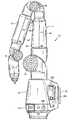
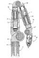
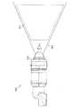
まず、図1〜図3を参照すると、本発明に係るCMMを、10に、概括的に示す。CMM10は、マルチジョイント式の、手動で操作される、多関節アーム14であって、一方の端部が、基部12に連結されており、もう一方の端部が、測定プローブ28に連結されている多関節アーム14を備える。アーム14は、基本的に、2種類のジョイント、すなわち、ロング(長い)ジョイント(スイベル動作を得るため)およびショート(短い)ジョイント(ヒンジ動作を得るため)で構成されている。ロングジョイントは、アームに沿って、実質的に軸方向に、つまり長手方向に配置されるが、ショートジョイントは、アームの縦軸に対して、90°に配置されるのが望ましい。ロングジョイントおよびショートジョイントは、一般に、2−2−2構成として知られている構成で対をなす(但し、例えば、2−1−2、2−1−3、2−2−3等のようなその他のジョイント構成を用いるようにしてもよい)。これらのジョイント対の各々を、図4〜図6に示す。 First, referring to FIGS. 1 to 3, a CMM according to the present invention is generally shown at 10. The CMM 10 is a multi-joint, manually operated, articulated
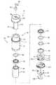
図4は、第1のジョイント対、すなわち、ロングジョイント16およびショートジョイント18の分解組立図を示す。また、図4は、携帯可能な電力供給電子回路20、携帯可能な電池パック22、磁気マウント24、および2つの部分からなる基部ハウジング26A,26Bを含む基部12の分解組立図を示す。これらの部品については、全て、以下に、より詳細に説明する。 FIG. 4 shows an exploded view of the first joint pair, ie, the
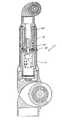
言うまでもないが、多関節アーム14の様々な主要部品の直径が、基部12からプローブ28の方に向かって、徐々に細くなっている(テーパー形状である)ということは重要なことである。このようなテーパー形状は、連続的なものであってもよく、また、図面に示した実施の形態のように、テーパー形状が、不連続的なもの、または段階的なものであってもよい。さらに、多関節アーム14の主要部品の各々を、螺合可能(threadably)に連結することによって、従来技術によるCMMに付随する数多くの固定具をなくすことができる。例えば、後述することではあるが、磁気マウント24は、第1のロングジョイント16に螺合可能に連結される。望ましくは、そのようなねじ切りは、テーパー形状のねじ切りであって、これは、自己ロック式(self-locking)であり、向上された軸方向/曲げ剛性を可能にするものである。代替的には、図25Aおよび図25Bに示すように、また、以下に説明するように、多関節アームの主要部品は、対応付けられたフランジを備えた相補的なテーパー形状のオス端部とメス端部とを有する場合もあり、そのようなフランジは、互いにボルト止めされる。 Needless to say, it is important that the diameters of the various main parts of the articulated
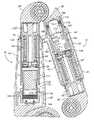
図5を参照すると、ロングジョイントおよびショートジョイントの第2のセットが、第1のセットに連結される状態で図示されている。第2のジョイントセットは、ロングジョイント30およびショートジョイント32を含む。磁気マウント24のロングジョイント16への連結と整合するように、ロングジョイント30は、ロングジョイント16の内側表面のねじ切りに螺合可能に連結される。同様に、図6を参照すると、第3のジョイントセットは、第3のロングジョイント34および第3のショートジョイント36を含む。第3のロングジョイント34は、第2のショートジョイント32の内側表面のねじ切りに螺合可能に連結する。以下に、さらに詳細に説明するように、プローブ28は、ショートジョイント36に螺合可能に連結する。 Referring to FIG. 5, a second set of long joints and short joints is shown coupled to the first set. The second joint set includes a
望ましくは、各々のショートジョイント18,32,36は、鋳造および/または機械加工されたアルミニウム部品、または、代替的に、軽量であって硬質の合金または複合材料で構成される。各々のロングジョイント16,30,34は、望ましくは、鋳造および/または機械加工されたアルミニウム、軽量であって硬質の合金および/または繊維強化ポリマーで構成される。3つの上述したジョイント対(すなわち、ジョイント対16,18を備えるペア1、ジョイント対30,32を備えるペア2、およびジョイント対34,36を備えるペア3)の機械軸は、円滑かつ均一な機械的な動作を得るために、基部に対して位置合わせされる。基部12からプローブ28にかけての上述したテーパー形状の構造は、より大きな荷重がかかる基部における剛性をより向上したものにする上で、また、使用時に遮るもののないことが重要なプローブまたはハンドルにおける断面をより小さなものにする上で好ましい。以下に、さらに詳細に説明するように、各々のショートジョイントには、そのいずれの端部にも保護緩衝材38が連結されており、各々のロングプローブは、保護スリーブ40または41で覆われている。言うまでもないが、第1のロングジョイント16は、第2および第3のロングジョイント30,34に対してスリーブ40,41によって提供されるのと同様のタイプの保護を提供する基部ハウジング26A,26Bによって保護されている。 Desirably, each
本発明の重要な特徴によれば、多関節アームにおけるジョイントの各々が、例えば、図7および図8に示したショートカートリッジ42およびロングカートリッジ44のようなモジュール式の軸受/エンコーダカートリッジを用いる。これらのカートリッジ42,44は、デュアルソケットジョイント46,48の開口部に取り付けられる。各々のソケットジョイント46,48は、第1の凹部つまりソケット120を有する第1の円筒形延長部分47および第2の凹部つまりソケット51を有する第2の円筒形延長部分49を含む。一般に、ソケット120,51は、互いに90°に配置されるが、その他の相対的な角度構成を用いる場合もある。ショートカートリッジ42は、デュアルソケットジョイント46,48の各ソケット51内に配置されて、ヒンジジョイントを構成する一方で、ロングカートリッジ44は、ジョイント46のソケット120(図25参照)内に配置されて、ロングカートリッジ44’(図26参照)は、ジョイント48のソケット120内に配置されて、各々が、長手方向のスイベルジョイントを構成する。モジュール式の軸受/エンコーダカートリッジ42,44によれば、モジュール式のエンコーダ部品が取り付けられる、予め圧力が加えられた、あるいは予荷重がかけられたデュアル軸受カートリッジを別々に製造することが可能となる。この軸受エンコーダカートリッジは、さらに、多関節アーム14の外部躯体部品(すなわち、デュアルソケットジョイント46,48)に固定的に連結することが可能である。このようなカートリッジを用いることは、当該分野における著しい進歩であるが、これは、そのことによって、多関節アーム14のこれらの複雑なサブコンポーネントを高品質かつ高速で生産することが可能となるからである。 In accordance with an important feature of the present invention, each of the joints in the articulated arm employs modular bearing / encoder cartridges such as, for example, the
本明細書において説明した実施の形態では、4つの異なるカートリッジタイプ、すなわち、ジョイント30,34のための2つのロング軸方向カートリッジ、ジョイント16のための1つの基部軸方向カートリッジ、ショートジョイント18のための1つの基部カートリッジ(カウンターバランスを含む)、およびジョイント32,36のための2つのヒンジカートリッジがある。さらに、多関節アーム14のテーパー形状と整合するように、基部に最も近い(例えば、ロングジョイント16およびショートジョイント18に位置する)カートリッジは、ジョイント30,32,34,36における比較的小さな直径と比べて、より大きな直径を有する。各々のカートリッジは、予荷重がかけられた軸受機構と、この実施の形態では、デジタルエンコーダを備える変換器と、を含む。続いて、図9および図10を参照して、軸方向ロングジョイント16内に配置されたカートリッジ44について説明する。 In the embodiment described herein, for four different cartridge types: two long axial cartridges for
カートリッジ44は、内スリーブ54および外スリーブ56によって分離された一対の軸受50,52を含む。軸受50,52に、予荷重がかけられているということは重要なことである。この実施の形態において、そのような予荷重は、締め付けたときに、所定の予荷重が、軸受50,52上に生じるように、異なる長さである(内スリーブ54は、外スリーブ56よりも、約0.0005インチ短い)スリーブ54,56によって与えられる。軸受50,52は、封止材58を用いて封止されており、このアセンブリは、シャフト60に回転可能に取り付けられている。その上面において、シャフト60は、シャフト上部ハウジング62で終端している。環状部63は、シャフト60とシャフト上部ハウジング62との間に画定されている。このアセンブリ全体は、シャフトとその軸受アセンブリが、内ナット66と外ナット68との組み合わせを用いて、ハウジング64にしっかりと固定された状態で、外カートリッジハウジング64の内部に配置される。なお、組み立てに際して、外ハウジング64の上部分65は、環状部63の内部に収容されることになる。言うまでもないが、上述した予荷重が、軸受50,52に与えられるのは、内ナット66および外ナット68を締め付けたときであって、これらが、軸受に対して圧縮力を与えるとともに、内スペーサ54および外スペーサ56の長さの違いによって、所望の予荷重が加えられることになる。 The
望ましくは、軸受50,52は、二重ボール軸受である。適切な予荷重を得るためには、軸受面が、可能な限り平行であることが重要である。この平行度が、軸受の外周周囲における予荷重の均一性に影響を及ぼす。不均一な荷重では、軸受に、粗くて不均一な回転トルク感触を与えることになり、結果として、予測がつかない径方向の回転振れおよびエンコーダ性能の低下をもたらすことになる。モジュール式に取り付けられたエンコーダディスク(後述)の径方向の回転振れは、結果として、読み取りヘッドの下方における望ましくないフリンジパターンシフトをもたらすことになる。これは、著しいエンコーダ角度測定エラーをもたらす。さらに、望ましくは二重軸受であるこの構造の剛性は、軸受間の間隔に直接的に関係がある。軸受間の隔たりが大きいほど、そのアセンブリの剛性は、より高くなる。スペーサ54,56は、軸受間の間隔を広げるために用いられる。カートリッジハウジング64は、アルミニウムであることが望ましいことから、さらに、スペーサ54,56もまた、アルミニウムを材料として作られて、長さおよび平行度が、高精度に機械加工されることが望ましい。その結果、温度変化によって、予荷重を損なうことになるであろう膨張差をもたらすことはない。既に述べたように、予荷重は、スペーサ54,56の長さにおいて、既に分かっているその長さの違いを組み込むことによって設定される。ナット66,68が完全に締め付けられると、この長さにおける差が、軸受予荷重をもたらすことになる。封止材58を用いて、封止された軸受が提供されるのは、その汚れが、どのような汚れであっても、あらゆる回転運動およびエンコーダの正確さに影響があるばかりではなく、ジョイント感触に影響があるからである。 Desirably, the
カートリッジ44には、間隔をあけて配置された一対の軸受が含まれることが望ましいが、代替的に、カートリッジ44が、単一の軸受、または3つ以上の軸受を含むようにしてもよい。このように、各々のカートリッジは、少なくとも1つの軸受を最低限必要とする。 The
本発明のジョイントカートリッジでは、回転に制限のない場合もあれば、代替として、回転が制限されている場合もある。制限された回転では、ハウジング64の外面上におけるフランジ72上の溝70によって、円筒形の軌道が提供されて、これに、シャトル74が収容される。シャトル74は、軌道70の内部を、それが、例えば、回転を停止させる止めねじ76のような、脱着可能なシャトル停止部に接するようになるまで進み、それ以上は、回転が起こらないようになっている。回転量は、どのくらいが望ましいかに応じて異なることが可能である。1つの好適な実施の形態において、シャトル回転は、720°未満に制限されるであろう。このタイプの回転シャトル停止部は、本願出願人が特許権者である米国特許第5,611,147号明細書に、より詳細に説明されており、その内容は全て、既に、本願に引用して援用されている。 In the joint cartridge of the present invention, there is a case where rotation is not limited, or alternatively, rotation is limited. For limited rotation, a
既に述べたように、1つの代替的な実施の形態において、本発明に用いられるジョイントは、その回転が制限されていない場合もある。この後者の場合においては、既に知られているスリップリングアセンブリが用いられる。望ましくは、シャフト60は、これを貫通する中空つまり軸方向の開口78を有しており、この一方の端部に、直径が、より大きい部分80を有する。軸方向の開口78,80の交差部分に画定された肩部を接合することで、円筒形のスリップリングアセンブリ82となる。スリップリングアセンブリ82は、モジュール式のジョイントカートリッジにおける上述した予荷重がかけられた軸受アセンブリに対して、非構造的である(すなわち、機械的な機能は、何ら提供せず、電気的および/または信号伝達機能を提供するにすぎない)。スリップリングアセンブリ82は、どのような市販のスリップリングで構成するようにしてもよいが、好適な実施の形態において、スリップリングアセンブリ82は、英国バークシャー州レディングのIDMエレクトロニクス社(IDM Electronics Ltd.)から入手可能なHシリーズスリップリングで構成される。そのようなスリップリングは、小型であり、円筒形のデザインを備えているので、シャフト60のなかの開口80において用いるのに最適である。シャフト60を貫通する軸方向の開口80は、アパーチャ84で終端しており、これは、スリップリングアセンブリ82からの配線を収容するような大きさおよび構成となっている経路86に連絡している。そのような配線は、所定の位置に固定されており、経路86およびアパーチャ84にパチンとはまって収容される配線カバー88によって保護されている。そのような配線は、図10において、90に概略的に図示されている。 As already mentioned, in one alternative embodiment, the joint used in the present invention may not be restricted in its rotation. In this latter case, a known slip ring assembly is used. Desirably, the
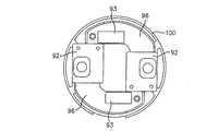
上述したように、モジュール式のカートリッジ44には、既に説明した、予荷重がかけられた軸受構造ばかりではなく、以下に説明する、モジュール式のエンコーダ構造の両方が含まれる。さらに、図9および図10を参照すると、本発明に用いる好適な変換器は、2つの主要な部品である読み取りヘッド92および格子ディスク94を有するモジュール式の光学エンコーダを備える。この実施の形態において、一対の読み取りヘッド92が、読み取りヘッド接続ボード96上に配置される。接続ボード96は、取り付けプレート100に(固定具98を介して)連結される。ディスク94は、望ましくは、シャフト60の下部軸受面102に(望ましくは、適切な接着剤を用いて)連結されており、読み取りヘッド92(プレート100によって支持および保持されている)から間隔をおいて、これに位置合わせして配置されることになる。配線ファンネル104および封止キャップ106によって、ハウジング64の下端部に最終的な外側の被覆が提供される。配線ファンネル104は、図10に最適な状態で図示されているように、配線90を、捕捉して、保持することになる。言うまでもないが、エンコーダディスク94は、102において接着剤を用いたことにより、シャフト60に保持されて、これとともに回転することになる。図9および図10は、ダブルの読み取りヘッド92を図示しているが、2つよりも多くの読み取りヘッドを用いてもよいし、代替的に、図9Aに示すような単一の読み取りヘッドを用いてもよいということは言うまでもない。図9B〜図9Eには、2つよりも多くの読み取りヘッドを備えたモジュール式のカートリッジ44の例を示す。図9Bおよび図9Cは、プレート100に収容された4つの読み取りヘッド92を、90°ずつ間隔をおいて配置された状態で示す(但し、異なる相対的な間隔が相応しい場合もある)。図9Dおよび図9Eは、プレート100に収容された3つの読み取りヘッド92を、120°ずつ間隔をおいて配置された状態で示す(但し、異なる相対的な間隔が相応しい場合もある)。 As described above, the
ディスク94を正しく位置合わせするために、穴(図示せず)が、ディスク94に隣接する位置にハウジング64を貫通して設けられる。さらに、工具(図示せず)を用いて、ディスク94を正しい位置合わせになるように押したところで、ディスク94とシャフト60との間の接着剤を硬化させて、ディスク94を所定の位置に固定する。さらに、穴栓73が、ハウジング64内の穴を貫通して設けられる。 In order to properly align the
ディスク94および読み取りヘッド92の位置を逆にして、ディスク94を、ハウジング56に連結させて、読み取りヘッド92をシャフト60とともに回転するようにしてもよいということは、重要な留意点である。そのような実施の形態を、図12Aに示すが、図中、ボード96’が、(接着剤を介して)シャフト60’に連結されるのは、それとともに回転するようにするためである。一対の読み取りヘッド92’が、ボード96’に連結されて、従って、シャフト60’とともに回転することになる。ディスク94’は、支持部100’上に配置されて、これは、ハウジング64’に連結される。いずれにせよ、ディスク94または読み取りヘッド92のどちらか一方を、シャフトとともに回転するように取り付けることができるということは言うまでもない。重要なことは、ディスク94および読み取りヘッド92が、光学的な通信状態を維持しつつ、互いに対して回転可能となるようにカートリッジ(またはジョイント)内に配置されるということだけである。 It is important to note that the position of
望ましくは、本発明において用いられる回転エンコーダは、米国特許第5,486,923号明細書および米国特許第5,559,600号明細書に開示されたものと同様であって、これらの明細書の内容は、その全てを、本願に引用して援用する。そのようなモジュール式のエンコーダは、ピュアプレシジョンオプティクス(Pure Precision Optics)という商品名でマイクロEシステムズ社(MicroE Systems)から市販されている。これらのエンコーダは、回折次数の間の干渉を検出することで、フリンジパターンに差し込まれた光検出器アレイ(例えば、読み取りヘッド)から、ほぼ完全な正弦波信号を生成する物理的な光学素子に基づいている。この正弦波信号を、電子的に補間することで、光学フリンジのほんの一部にすぎない変位を検出することが可能となる。 Desirably, the rotary encoder used in the present invention is similar to those disclosed in US Pat. No. 5,486,923 and US Pat. No. 5,559,600. Is incorporated herein by reference in its entirety. Such a modular encoder is commercially available from MicroE Systems under the trade name Pure Precision Optics. These encoders detect the interference between diffraction orders, from a photodetector array (eg, a read head) inserted into a fringe pattern into a physical optical element that generates a nearly complete sinusoidal signal. Is based. By interpolating the sine wave signal electronically, it is possible to detect a displacement that is only a part of the optical fringe.
レーザ光源を用いて、レーザビームは、まず、レンズによって平行化されて、続いて、アパーチャによって大きさが調整される。大きさが調整された平行ビームが、光を離散的な次数に回折させる格子を通過すると、0次および全ての偶数次は、格子構造によって除去される。0次が除去されると、発散する3次を超える領域が、存在しており、ここでは、±1次のみが重複して、ほぼ純粋な正弦波干渉がもたらされる。1つまたは複数の光検出器アレイ(読み取りヘッド)が、この領域に配置されて、格子と検出器との間に相対的な動きがあるときに、4チャンネルのほぼ純粋な正弦波出力を生成する。電子回路によって、その出力は、所望のレベルの分解能に増幅、正規化、および補間される。 Using a laser light source, the laser beam is first collimated by a lens and subsequently sized by an aperture. When a sized parallel beam passes through a grating that diffracts light into discrete orders, the zeroth order and all even orders are removed by the grating structure. When the 0th order is removed, there is a region beyond the 3rd order that diverges, where only the ± 1st order overlaps, resulting in nearly pure sinusoidal interference. One or more photodetector arrays (readheads) are placed in this area to produce a 4-channel, almost pure sine wave output when there is relative movement between the grating and the detector To do. The electronic circuit amplifies, normalizes, and interpolates the output to the desired level of resolution.
このエンコーダのデザインが簡単であることによって、従来の光学エンコーダと比較して、いくつかの利点が得られる。測定が、レーザ源とその平行化するための光学素子、回折格子、および検出器アレイのみを用いて行うことができる。その結果、比較的かさばる従来の通常のエンコーダと比べて、極めて小型のエンコーダシステムが得られる。また、格子とフリンジの動きとの間の直接的な関係によって、このエンコーダは、従来の機器が影響を受けやすい、環境的に引き起こされた誤差に影響を受けにくい。さらに、干渉の領域が大きいので、また、この領域のいたるところで、ほぼ正弦波の干渉が得られるので、位置合わせ許容範囲が、従来のエンコーダの場合よりもはるかに緩やかである。 The simplicity of this encoder design provides several advantages over conventional optical encoders. Measurements can be made using only the laser source and its collimating optics, diffraction grating, and detector array. As a result, an extremely small encoder system can be obtained as compared with the conventional encoder which is relatively bulky. Also, due to the direct relationship between the grating and the fringe movement, the encoder is less susceptible to environmentally induced errors that are sensitive to conventional equipment. Furthermore, since the area of interference is large and almost sinusoidal interference is obtained throughout this area, the alignment tolerance is much more gradual than in the case of a conventional encoder.
上述の光学エンコーダの著しい利点としては、スタンドオフの向きおよび距離、つまり読み取りヘッドのエンコーダディスクに対する向きおよび距離の精度は、厳密さがはるかに低いということがある。これによって、高い精度の回転方向の測定と、組み立てやすいパッケージと、が可能になる。この「形状的に許容性がある」エンコーダ技術を用いた結果として、著しいコストの低下と製造の容易さを備えたCMM10が得られる。 A significant advantage of the optical encoder described above is that the accuracy of the standoff orientation and distance, ie the orientation and distance of the read head relative to the encoder disk, is much less stringent. This enables highly accurate measurement of the direction of rotation and easy packaging. As a result of using this “geometrically acceptable” encoder technique, a
言うまでもないが、上述した好適な実施の形態においては、光学ディスク94が含まれているが、本発明の好適な実施の形態は、同様に、読み取りヘッドが相対的な動きを測定することを可能にするあらゆる光学フリンジパターンを包含する。ここで用いたように、そのようなフリンジパターンとは、動きの測定を可能にするあらゆる周期的なアレイ状の光学素子を意味する。そのような光学素子つまりフリンジパターンは、上述したように、回転ディスクまたは固定ディスクに取り付けることが可能であろうし、また、代替的に、カートリッジの相対的可動部品(例えば、シャフト、軸受、ハウジング等)のいずれかの上に、堆積、固定、またはその他のやり方で配置され、あるいは、存在することが可能であろう。 Of course, while the preferred embodiment described above includes an
実際、読み取りヘッドおよび対応付けられた周期的なアレイつまりパターンは、必ずしも、光学素子(上述)に基づいたものである必要は全くない。むしろ、より広義においては、読み取りヘッドは、動き、一般には、回転運動を測定するために用いることが可能なその他の何らかの測定可能な量または特性のその他の何らかの周期的なパターンを読み取る(検知する)ことが可能であろう。そのようなその他の測定可能な特性としては、例えば、反射率、不透明度、磁界強度、キャパシタンス、インダクタンス、または表面粗さが含まれる場合がある。(なお、表面粗さパターンを、例えば、CCDカメラのようなカメラの形態をとった読み取りヘッドつまりセンサを用いて読み取ることも可能であろう。)そのような場合において、読み取りヘッドは、例えば、磁界強度、反射率、キャパシタンス、インダクタンス、表面粗さ等の周期的な変化を測定するであろう。従って、ここで用いたように、「読み取りヘッド」という用語は、これらの測定可能な量または特性の分析のためのあらゆるセンサまたは変換器および対応付けられた電子回路を意味しており、光学読み取りヘッドは、1つの好適な例であるにすぎない。当然、読み取りヘッドによって読み取られている周期的なパターンは、読み取りヘッドと周期的なパターンとの間に相対的な動き(一般に、回転運動)がある限り、あらゆる表面上に存在することが可能である。周期的なパターンの例としては、回転部品または固定部品の上にパターン状に堆積させられた磁気媒体、電磁誘導媒体、または容量性媒体が含まれる。また、表面粗さが、読み取られる周期的なパターンである場合に、対応付けられた読み取りヘッド(おそらく、例えば、CCDカメラのようなカメラ)と通信状態にあるいずれの部品の表面粗さを用いるようにしてもよいので、別の周期的な媒体を、堆積またはその他のやり方で設ける必要はない。 In fact, the read head and the associated periodic array or pattern need not necessarily be based on optical elements (described above). Rather, in a broader sense, the read head reads (senses) some other periodic pattern of movement, generally any other measurable quantity or characteristic that can be used to measure rotational movement. ) Would be possible. Such other measurable characteristics may include, for example, reflectivity, opacity, magnetic field strength, capacitance, inductance, or surface roughness. (Note that the surface roughness pattern could be read using a read head or sensor in the form of a camera such as a CCD camera, for example.) In such a case, the read head may be, for example, Periodic changes such as magnetic field strength, reflectivity, capacitance, inductance, surface roughness, etc. will be measured. Thus, as used herein, the term “readhead” means any sensor or transducer and associated electronic circuit for the analysis of these measurable quantities or properties, and the optical reading The head is just one suitable example. Of course, the periodic pattern being read by the read head can exist on any surface as long as there is a relative movement (generally a rotational movement) between the read head and the periodic pattern. is there. Examples of periodic patterns include magnetic media, electromagnetic induction media, or capacitive media deposited in a pattern on rotating or stationary components. Also, if the surface roughness is a periodic pattern to be read, the surface roughness of any component in communication with the associated read head (probably a camera such as a CCD camera) is used. As such, no separate periodic media need be deposited or otherwise provided.
上述したように、図9および図10には、軸方向に長いロングジョイント16のモジュール式の軸受およびエンコーダカートリッジの各要素を示す。図11および図12には、軸方向に長いロングジョイント30,34の軸受およびエンコーダカートリッジを示す。これらのカートリッジアセンブリは、図9および図10に示したものと実質的に同様であり、44’で示す。軽微な違いが、各図から、カートリッジ44を基準として、例えば、異なる構成の配線キャップ/カバー88’、わずかに異なる配線ファンネル/カバー104’,106’、ハウジング64’の上端部におけるフランジ72’の配置に関して明らかである。また、ハウジング64’とシャフト上部ハウジング62との間のフランジは、外側に向かって広がっている。当然、図11および図12に示した様々な部品の相対的な長さは、図9および図10に示したものと多少異なる場合もある。これらの部品は、全て、実質的に同様のものであるから、各部品について、プライム(’)を付けた同一の符号が付されている。図11Aは、図11と同様であるが、単一の読み取りヘッドの実施の形態を示す。 As described above, FIGS. 9 and 10 show the elements of the modular bearing and the encoder cartridge of the long joint 16 that is long in the axial direction. FIG. 11 and FIG. 12 show the bearings and encoder cartridges of the
さらに、図13および図14には、ショートヒンジジョイント32,36の軸受およびエンコーダカートリッジについて、同様の分解組立図および断面図を示す。図11および図12のロング軸方向ジョイント44’の場合と同様に、ショートヒンジジョイント32,36のカートリッジは、詳細に上述したカートリッジ44と実質的に同様であって、従って、これらのカートリッジの各部品は、44’’において特定されて、同様の部品が、ダブルプライム(’’)を用いて特定されている。言うまでもないが、カートリッジ44’’は、ショートジョイント32,36に用いるためのものであるので、スリップリングアセンブリが必要とされることはなく、配線は、これらのジョイントのヒンジ動作により、単に、軸方向の開口78’’,80’’を貫通することになる。図13Aは、図13と同様であるが、単一の読み取りヘッドの実施の形態を示す。 Further, FIGS. 13 and 14 show similar exploded views and sectional views of the bearings and encoder cartridges of the short hinge joints 32 and 36, respectively. As in the case of the long axial joint 44 'of FIGS. 11 and 12, the cartridges of the short hinge joints 32, 36 are substantially similar to the
最後に、図15および図16を参照すると、ショートヒンジジョイント18のモジュール式の軸受/エンコーダカートリッジが、108に図示されている。言うまでもないが、カートリッジ108のほぼ全ての部品が、カートリッジ44,44’,44’’における各部品と同様または同一であって、重要な例外としては、カウンタバランスアセンブリを含むという点がある。このカウンタバランスアセンブリには、ハウジング64’’の上方に収容されたカウンタバランススプリング110が含まれており、CMM10に重要なカウンタバランス機能を提供する。図15Aは、図15と同様であるが、単一の読み取りヘッドの実施の形態を示す。 Finally, referring to FIGS. 15 and 16, a modular bearing / encoder cartridge for the short hinge joint 18 is illustrated at 108. Of course, almost all parts of the
上述したように、好適な実施の形態において、1つよりも多くの読み取りヘッドを、エンコーダに用いるようにしてもよい。言うまでもないが、エンコーダの角度測定は、加えられた荷重によるディスクの心振れつまり径方向の動きによって行われる。2つの読み取りヘッドが、互いに180°の角度で配置されていることで、結果として、各々の読み取りヘッドにおいて相殺効果を生じさせる心振れをもたらすことになるということが確認されている。これらの相殺効果を平均して、最終的な「耐性のある」角度測定値を求める。このように、2つの読み取りヘッドを用いること、およびその結果として得られる誤差相殺によって、より誤差の生じにくい、より正確なエンコーダ測定値がもたらされることになる。図17〜図19には、それぞれ、例えば、ジョイント16,18(すなわち、基部の最も近くにあるジョイント)において見られるような、より大きな直径のカートリッジにおいて有用な、デュアル読み取りヘッドの実施の形態についての底面図、断面図、上面図を示す。さらに、カートリッジ端部キャップ100は、そこに一対の回路基板96を取り付けており、各々の回路基板96が、そこに機械的に連結された読み取りヘッド92を備えている。読み取りヘッド92は、望ましくは、互いに180°離して配置されており、ディスクの心振れつまり径方向の動きから結果として生じる誤差相殺を可能にする。各々の基板96は、さらに、その回路基板96を内部バスおよび/またはその他の配線に連結するためのコネクタ93を含んでおり、これについては、以下にさらに説明する。図20〜図22には、図17〜図19において示したのと実質的に同一の部品を示すが、主要な違いとしては、より小さい直径のカートリッジ端部キャップ100である。このより小さい直径のデュアル読み取りヘッドの実施の形態は、例えば、ジョイント30,32,34,36のより小さい直径のカートリッジと対応付けられるであろう。 As described above, in preferred embodiments, more than one read head may be used in an encoder. Needless to say, the angle measurement of the encoder is performed by the runout or radial movement of the disk due to the applied load. It has been observed that the two read heads are arranged at an angle of 180 ° to each other, resulting in a runout that produces a canceling effect at each read head. These offset effects are averaged to determine the final “resistant” angle measurement. Thus, the use of two read heads and the resulting error cancellation results in a more accurate encoder measurement that is less error prone. FIGS. 17-19 illustrate dual read head embodiments useful in larger diameter cartridges, such as found, for example, at
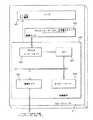
さらに、図23Aには、図9A、図11A、図13Aおよび図15Aの単一の読み取りヘッドの実施の形態について、電子回路のブロック図を示す。言うまでもないが、CMM10には、望ましくは、外部バス(望ましくは、USBバス)260および内部バス(望ましくは、RS−485)261が含まれており、これは、より多くのエンコーダのためばかりではなく、外部に取り付けられたレールまたは例えば7番目の軸のような追加の回転軸のために拡張可能なように設計されている。内部バスは、望ましくは、RS485と整合性があって、このバスは、望ましくは、同一出願人による米国特許第6,219,928号明細書に開示されたような携帯可能なCMMアームにおいて変換器からデータを通信するためのシリアルネットワークと整合性があるように、シリアルネットワークとして用いられるように構成されており、この明細書の内容は、その全てを本願に引用して援用する。 Further, FIG. 23A shows an electronic circuit block diagram for the single read head embodiment of FIGS. 9A, 11A, 13A, and 15A. Needless to say, the
図23Aを参照すると、言うまでもないが、各々のカートリッジにおける各々のエンコーダは、エンコーダ基板に対応付けられている。ジョイント16におけるカートリッジのためのエンコーダ基板は、基部12の内部に配置されており、図25において112に特定されている。ジョイント18,30のためのエンコーダは、デュアルエンコーダ基板上において処理されるが、これは、第2のロングジョイント30内に位置しており、図26において114に特定されている。また、図26は、ジョイント32,34に用いるエンコーダのための同様のデュアルエンコーダ基板116を示しており、この基板116は、図26に示したように、第3のロングジョイント34内に配置されている。最後に、端部エンコーダ基板118が、図24に示すように、測定プローブハンドル28の内部に配置されており、ショートジョイント36においてエンコーダを処理するために用いられる。各々の基板114,116,118は、熱電対に対応付けられており、温度の過渡的な事象による熱補償を可能にする。各々の基板112,114,116,118は、組み込まれたアナログデジタル変換手段、エンコーダ計数手段およびシリアルポート通信手段を内蔵する。また、各々の基板は、読み取りプログラム可能なフラッシュメモリを有することで、動作データの局部記憶を可能にしている。また、メインプロセッサ基板112は、外部USBバス260を介して現場でプログラム書き込みすることも可能である。上述したように、内部バス(RS−485)261は、より多くのエンコーダのために拡張可能なように設計されており、また、これには、外部に取り付けられたレールおよび/または7番目の回転軸が含まれる。軸ポートが、内部バスの診断を提供するように設けられている。これらの図面において10に図示したタイプの複数のCMMを、外部USB通信プロトコルの機能により、単一の適用先(アプリケーション)に連結することもできる。さらに、全く同一の理由から、複数の適用先(アプリケーション)を、単一のCMM10に連結することもできる。 Referring to FIG. 23A, it goes without saying that each encoder in each cartridge is associated with an encoder board. The encoder board for the cartridge at joint 16 is located inside
望ましくは、各々の基板112,114,116,118には、例えば、モトローラ社(Motorola)からDSP56F807の型番で入手可能なプロセッサのような、16ビットのデジタル信号プロセッサが含まれる。この単一の処理部品は、シリアル通信、直交復調、A/Dコンバータ、およびオンボードメモリを含む数多くの処理機能を兼ね備えており、従って、各々の基板に必要とされるチップの総数を少なくすることを可能にする。 Preferably, each
本発明のもう1つの重要な特徴によれば、各々のエンコーダは、個々に設けられた識別チップ120に対応付けられている。このチップは、各々の個別のエンコーダを特定することになるので、従って、品質管理、検査、および修理を容易にするとともに迅速化するように、各々の個別の軸受/エンコーダモジュール式カートリッジを特定することになる。 According to another important feature of the invention, each encoder is associated with an individually provided
図23Bは、図23Aと同様の電子回路ブロック図であるが、図10、図12、図14および図16〜図22のデュアル読み取りヘッドの実施の形態を示す。 FIG. 23B is an electronic circuit block diagram similar to FIG. 23A, but showing the embodiment of the dual read head of FIGS. 10, 12, 14 and 16-22.
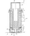
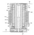
図24〜図26を参照して、多関節アーム14における各々のカートリッジの組み立てについて、さらに説明する(なお、図24には、基部12を含まないアーム10を示す。また、図24〜図26では、図9A、図11A、図13Aおよび図15Aの単一の読み取りヘッドの実施の形態を用いる)。図25に示すように、第1のロングジョイント16には、比較的長いカートリッジ44が含まれており、その上端部は、デュアルソケットジョイント46の円筒形のソケット120に差し込まれている。カートリッジ44は、適切な接着剤を用いてソケット120のなかにしっかりと保持される。カートリッジ44の反対側の端部である下端部は、延長チューブに差し込まれるが、これは、この実施の形態では、アルミニウム製のスリーブ122であってもよい(但し、スリーブ122は、硬質の合金または複合材料で構成されてもよい)。カートリッジ44は、再度、適切な接着剤を用いてスリーブ122内に固定される。スリーブ122の下端部は、外径が、より大きい部分124を含み、その上に、内ねじ切り126を有する。そのようなねじ切りは、外側に向かってテーパー形状であって、図4に明らかに示すように、磁気マウントハウジング130上において内側に向かってテーパー形状であるねじ切り128と螺合可能に嵌合するように構成される。既に述べたように、CMM10のいくつかのジョイントは、全て、そのようなテーパー形状のねじ切りを用いて相互に接続される。望ましくは、このテーパーねじは、自己締め付け式であるNPTタイプのものであり、従って、ロックナットまたはその他の固定機構は、全く必要ない。また、このねじ切りは、ねじロック剤を許容するものであり、これを含むであろう。 The assembly of each cartridge in the articulated
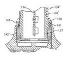
図26を参照すると、第1のロングジョイント16においてと同様に、ロングカートリッジ44’は、デュアルソケットジョイント46’の円筒形の開口120’に接着固定される。カートリッジ44’の外ハウジング64’には、フランジ72’の下側表面によって画定された肩部132が含まれる。この肩部132は、ハウジング64’の外側表面の上方に、これを取り囲むように設けられた円筒形の延長チューブ134を支持する。延長チューブは、各ジョイントにおいて、ねじ切りされた部品に連結するための調節可能な長さのチューブをつくるために用いられる。延長チューブ134は、従って、カートリッジ64’の底部から外側に向かって延在しており、そのなかに、ねじ切りされたスリーブ136を差し込んでいる。適切な接着剤が、ハウジング44’を延長チューブ134に接着するとともに、スリーブ136とチューブ134とを互いに接着するために用いられる。スリーブ136は、テーパー部分が、その上に、外ねじ切り138を有するところで終端する。外ねじ切りは、デュアルソケットジョイント48の開口144内に接着固定されている接続部142上において、内ねじ切り140と螺合可能に嵌合する。望ましくは、延長チューブ134は、例えば、適切な炭素繊維複合材料のような、複合材料で構成される一方で、螺合可能なスリーブ136は、デュアルソケットジョイント48の熱特性に適合するようにアルミニウムで構成される。言うまでもないが、PC(プリント回路)基板114が、支持部146に固定されて、さらに、これが、デュアルソケットジョイント支持部142に固定される。 Referring to FIG. 26, as in the first long joint 16, the long cartridge 44 'is adhesively fixed to the cylindrical opening 120' of the dual socket joint 46 '. The
上述したねじ切りされた接続部に加えて、各ジョイントのうちの1つ、一部、または全てを、図25Aおよび図25Bに示したようなねじ切りされた固定具を用いて相互に接続するようにしてもよい。図26のねじ切りされたスリーブ136の代わりに、図25Bのスリーブ136’は、滑らかなテーパー形状の端部137を有しており、これは、相補的なテーパー形状のソケット支持部142’に収容される。フランジ139は、スリーブ136’から外側に向かって円周状に延在しており、それを貫通するボルト穴アレイ(この場合は、6穴)が、ねじ切りされたボルト141を収容するために備えられている。ボルト141は、ソケット支持部142’の上側表面に沿って、対応する穴に螺合可能に収容される。延長チューブ134’は、図26の実施の形態においてと同様に、スリーブ136’の上方に収容される。各ジョイントのための相補的なテーパー形状のオス相互接続部とメス相互接続部とによって、従来と比べて向上した接続インターフェースが提供される。 In addition to the threaded connection described above, one, some, or all of each joint is connected to each other using a threaded fixture as shown in FIGS. 25A and 25B. May be. Instead of the threaded
さらに、図26を参照すると、第3のロングジョイント34のロングカートリッジ44’’は、ロングジョイント30のカートリッジ44’と同様のやり方で、アーム14に固定されている。すなわち、カートリッジ44’’の上部分は、デュアルソケットジョイント46’’の開口120’’のなかに接着固定されている。延長チューブ148(望ましくは、チューブ134について述べたような複合材料で構成されている)は、外ハウジング64’’の上方に配置されており、そこから外側に向かって延在して、嵌合スリーブ150を収容するようにして、これを、延長チューブ148の内径に接着固定する。嵌合スリーブ150は、テーパー部分が、外ねじ切り152を有するところで終端しており、デュアルソケットジョイント148’の内部において円筒形のソケット156に接着連結されているデュアルソケットジョイント支持部154上における相補的な内ねじ切り153と嵌合する。プリント回路基板116は、同様に、デュアルソケットジョイント支持部154に固定されたPCB支持部146’を用いて、デュアルソケットジョイントに接続される。 Further, referring to FIG. 26, the
図7および図8について述べたように、図13および図14におけるショートカートリッジ44’および図15の108は、単に、2つのデュアルソケットジョイント46,48の間に配置されており、デュアルソケットジョイントの内部において適切な接着剤を用いて固定される。結果として、ロングカートリッジおよびショートカートリッジは、互いに、直角(あるいは、所望の場合には、直角以外の角度)で、容易に連結される。 7 and 8, the short cartridge 44 'in FIGS. 13 and 14 and 108 in FIG. 15 are simply disposed between the two dual socket joints 46 and 48, and the dual socket joint It is fixed inside with a suitable adhesive. As a result, the long cartridge and the short cartridge are easily connected to each other at a right angle (or an angle other than a right angle if desired).
上述したようなモジュール式の軸受/変換器カートリッジは、例えば、ラーブ(Raab)に付与された米国特許第5,794,356号明細書およびイートン(Eaton)に付与された米国特許第5,829,148号明細書において示したような、携帯可能なCMMにおける重要な技術的進歩を構成する。これは、カートリッジ(または、カートリッジのハウジング)が、多関節アームを構成する各々のジョイントの構成要素を実際に画定するからである。ここで用いたように、「構成要素」とは、カートリッジ(例えば、カートリッジハウジング)の表面が、アームの変形を伴うことなく(あるいは、最大でも、ほんの少しの変形を伴うのみで)回転を伝達するために、多関節アームの別の構成部品に固定的に連結されているということを意味する。これは、独立した別個のジョイント要素と伝達要素とが必要とされており、回転エンコーダが、ジョイント要素の一部である(但し、伝達要素ではない)、従来の携帯可能なCMM(例えば、ラーブの‘356号特許およびイートンの‘148号特許に開示されたようなCMM)と対照的である。要するに、本発明によれば、ジョイント要素および伝達要素の機能性を組み合わせて、単一のモジュール式の部品(すなわち、カートリッジ)にすることによって、独立した伝達要素(例えば、伝達部材)の必要性が解消されている。このように、独立した別個のジョイントおよび伝達部材で構成された多関節アームの代わりに、本発明においては、より長いジョイント要素およびより短いジョイント要素(すなわち、カートリッジ)の組み合わせで構成された多関節アームを用いており、これらのジョイント要素の全てが、そのアームの構成要素である。これは、従来の技術に比べて効率向上につながる。例えば、‘148号特許および‘582号特許におけるジョイント/伝達部材の組み合わせにおいて用いられた軸受の数は、4つ(ジョイントにおける2つの軸受および伝達部材における2つの軸受)であったのに対して、本発明のモジュール式の軸受/変換器カートリッジでは、最低の1つの軸受を(但し、2つの軸受のほうが望ましい)用いることができるだけでなく、これまでどおり同様の機能性を(但し、異なる、より向上したやり方で)達成することができる。 Modular bearing / transducer cartridges such as those described above are described, for example, in US Pat. No. 5,794,356 to Raab and US Pat. No. 5,829 to Eaton. 148, which constitutes an important technical advancement in portable CMMs. This is because the cartridge (or cartridge housing) actually defines the components of each joint that make up the articulated arm. As used herein, a “component” refers to the rotation of the surface of a cartridge (eg, a cartridge housing) without any arm deformation (or at most, only slight deformation). This means that it is fixedly connected to another component of the articulated arm. This requires a separate and separate joint element and transmission element, and a conventional portable CMM (eg, a Lab) where the rotary encoder is part of the joint element (but not the transmission element). In contrast to the CMM) disclosed in the '356 patent and the Eton' 148 patent. In summary, according to the present invention, the need for independent transmission elements (eg, transmission members) by combining the functionality of joint elements and transmission elements into a single modular part (ie, cartridge). Has been resolved. Thus, instead of a multi-joint arm composed of independent and separate joints and transmission members, in the present invention, a multi-joint composed of a combination of a longer joint element and a shorter joint element (ie, cartridge) An arm is used, and all of these joint elements are components of that arm. This leads to an improvement in efficiency compared to the conventional technology. For example, the number of bearings used in the joint / transmission member combination in the '148 and' 582 patents was four (two bearings in the joint and two bearings in the transmission member). In the modular bearing / transducer cartridge of the present invention, not only can a minimum of one bearing be used (but two bearings are preferred), but the same functionality as before (but different, Can be achieved).
図24A、図26Aおよび図26Bは、図24〜図26と同様の断面図であるが、図10、図12、図14および図16〜図22のデュアル読み取りヘッドの実施の形態を示しており、さらに、図3Aに示したCMM10’の断面図である。 24A, 26A, and 26B are cross-sectional views similar to FIGS. 24-26, but showing the dual read head embodiment of FIGS. 10, 12, 14, and 16-22. 3C is a cross-sectional view of the
多関節アーム14の全長および/または様々なアーム部分は、その所期の用途に応じて様々であろう。1つの実施の形態において、多関節アームは、約24インチの全長を有して、約0.0002インチ〜約0.0005インチのオーダーの測定値を提供する場合がある。このアーム寸法および測定精度では、現在、例えば、マイクロメータ、ハイトゲージ、キャリパ等のような、一般的な手持ちの器具を用いて達成されている測定に好適な携帯可能なCMMが提供される。当然のことながら、多関節アーム14が、より小さな寸法またはより大きな寸法およびより低い精度レベルまたはより高い精度レベルを有することも可能であろう。例えば、より大きなアームは、全長が、8フィートまたは12フィートであって、対応付けられた測定精度が、0.001インチである場合があり、これによって、ほとんどの即時検査の用途に用いること、またはリバースエンジニアリングに用いることを可能にする。 The overall length of the articulated
また、CMM10は、それに取り付けられたコントローラとともに用いて、上述の米国特許第5,978,748号明細書および米国特許出願第09/775,226号明細書において開示されたように、比較的簡単な実行可能なプログラムを実行するために用いることができるし、また、ホストコンピュータ172上のより複雑なプログラムに用いることもできる。 The
図1〜図6および図24〜図26を参照すると、好適な実施の形態において、ロングジョイントおよびショートジョイントの各々は、エラストマ緩衝材またはカバーによって保護されており、これは、衝撃の大きいショックを抑制するとともに、人間工学的に快適なグリップ位置(および見た目に美しい外観)を提供するように機能する。ロングジョイント16,30,34は、全て、硬質プラスチック(例えば、ABS)製の交換可能なカバーによって保護されており、これは、衝撃および摩耗に対するプロテクタとしての役割を果たす。第1のロングジョイント16の場合は、この硬質プラスチック製の交換可能なカバーは、図4にも示したように、2つの部分からなる基部ハウジング26A,26Bの形で提供されている。ロングジョイント30,34は、それぞれ、一対のカバー部分40,41によって保護されており、これは、図5および図6に示すように、保護スリーブを形成するように、適切なねじを用いて二枚貝の貝殻(クラムシェル)状に互いに固定することができる。言うまでもないが、好適な実施の形態において、各々のロングジョイント30,34のための、この硬質プラスチック製の交換可能なカバーによって、望ましくは、複合材料(炭素繊維)製である延長チューブ134,148が、それぞれ、取り囲まれることになる。 With reference to FIGS. 1-6 and 24-26, in the preferred embodiment, each of the long and short joints is protected by an elastomeric cushion or cover, which provides high impact shock. It functions to suppress and provide an ergonomically comfortable grip position (and a visually pleasing appearance). The
望ましくは、これらのカバーの1つ、すなわち、この場合は、カバー部分41には、それに一体成形された傾斜支持支柱166が含まれており、これによって、プローブ28が、停止位置にあるときに基部12にぶつからないように、アームの肘部分における回転を制限する。これは、図3、図24および図26に、最適な状態で図示されている。言うまでもないが、支柱166は、このようにして、不必要な衝撃および摩耗を抑制することになる。 Desirably, one of these covers, in this case the
また、図29および図31について、以下に説明するように、プローブ28は、硬質プラスチック材料でつくられた交換可能なプラスチック保護カバーを含む場合もある。 29 and 31,
図3A、図24A、図26Aおよび図26Bには、代替的な保護スリーブ40’,41’を示しており、これらもまた、クラムシェル構造を有するが、ねじ切りされた固定具の代わりに、ストラップまたはスプリングクリップ167を用いて所定の位置に保持される。 3A, 24A, 26A and 26B show alternative protective sleeves 40 ', 41', which also have a clamshell structure, but instead of threaded fasteners, straps Alternatively, the
ショートジョイント18,32,36の各々には、上述したように、また、図1〜図3、図5および図6に明らかに示すように、一対のエラストマ(例えば、スタントプレン(Stantoprene)(登録商標)のような熱可塑性ゴム)製の緩衝材38が含まれる。緩衝材38は、ねじ切りされた固定具または適切な接着剤を用いて連結してもよいし、その他の適切ないずれかのやり方で連結してもよい。エラストマまたはゴム製の緩衝材38によって、衝撃の大きいショックが抑制されるばかりではなく、見た目に美しく、人間工学的に快適なグリップ位置が提供されることになる。 Each of the
上述のカバー40,41,40’,41’および緩衝材38は、全て、簡単に交換することが(基部ハウジング26A,26Bと同様に)可能であるので、アーム14は、CMM10の機械的な性能に影響を与えることなく、速やかに、かつ安価で修繕することが可能となる。 Since the above-described
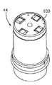
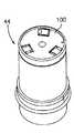
引き続き、図1〜図3を参照すると、基部ハウジング26A,26Bには、図3の168に示すように、少なくとも2つの円筒形の突起が、球面の取り付け用に含まれる。この球面は、クランプタイプのコンピュータホルダ170の取り付けに用いることができるが、これによって、さらに、携帯可能なまたはその他のコンピュータ機器172(例えば、「ホストコンピュータ」)が支持される。望ましくは、円筒形の突起が、基部ハウジング26A,26Bのいずれの側面にも設けられるので、ボールおよびクランプによるコンピュータマウントを、CMM10のいずれの側面にも取り付けることができる。 With continued reference to FIGS. 1-3, the
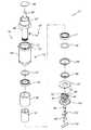
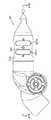
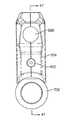
次に、図27および図28A〜図28Cを参照して、測定プローブ28の好適な実施の形態について、以下に説明する。プローブ28には、ハウジング196が含まれており、そのなかに、プリント回路基板118を収容するための内部空間198を有する。言うまでもないが、ハウジング196は、上述したタイプのデュアルソケットジョイントを構成しており、回路基板118を支持するための支持部材199が接着されるソケット197を含む。望ましくは、ハンドル28は、2つのスイッチ、すなわち捕捉スイッチ200および確認スイッチ202を備える。操作者は、これらのスイッチを用いて、操作中に、測定値を捕捉(捕捉スイッチ200)するとともに、その測定値を確認(確認スイッチ202)する。本発明の重要な特徴によれば、これらのスイッチは、互いに、違いを明確にすることで、使用に際して、取り違えることをできるだけ少なくする。このように違いを明確にすることは、例えば、スイッチ200,202が、異なる高さおよび/または異なる手触り(なお、スイッチ202は、スイッチ200の滑らかな上面とは対照的に、凹凸(identation)を有する)および/または異なる色(例えば、スイッチ200は、緑色であってもよく、スイッチ202は、赤色であってもよい)であることを含む1つまたは複数の形で実現できる。また、本発明の重要な特徴によれば、表示灯204が、正常なプローブ検出が行われていることを表示するために、スイッチ200,202と対応付けられている。望ましくは、表示灯204は、2色灯であり、例えば、灯204は、測定値を捕捉(緑色の捕捉ボタン200を押下)しているときは緑色であって、測定値を確認(赤色の確認ボタン202を押下)している間は赤色である。多色灯を用いることは、既に知られているLEDを灯204の光源として用いることで容易に達成される。グリップを助けるために、また、美観の向上および耐衝撃性を提供するために、上述したタイプの外側の保護被覆が、206に特定されており、プローブ28の一部を覆うように設けられている。スイッチ回路基板208が、ボタン200,202およびランプ204を取り付けるために設けられており、支持部材199によって支持されている。スイッチ基板208は、基板118と電気的に相互接続されており、これは、スイッチおよび表示灯を処理するためばかりではなく、ショートヒンジジョイント36の処理をするための部品を収容する。 Next, a preferred embodiment of the
本発明のもう1つの重要な特徴によれば、また、図27および図28A〜図28Cを参照すると、プローブ28には、恒久的に取り付けられたタッチトリガプローブばかりではなく、タッチトリガプローブを保護しつつ固定プローブを適応させるための脱着可能なキャップが含まれる。タッチプローブ機構は、図27において210に図示されており、簡単な3点キネマティックシートを土台としている。この従来の構成においては、コンタクトスプリング216によってバイアスがかけられたボール214に接触するノーズ212を備える。3つのコンタクトピン(1つのピンが、218に図示されている)が、下にある電気回路と接触している。プローブノーズ212に対して何らかの力を加えると、結果として、3つのコンタクトピン218のいずれか1つを持ち上げることになり、下にある電気回路を開くことになり、従って、スイッチを作動させることになる。望ましくは、タッチトリガプローブ210は、前面の「捕捉」スイッチ200と連係して動作することになる。 According to another important feature of the present invention and with reference to FIGS. 27 and 28A-28C, the
図28Bに示すように、タッチトリガプローブ210を用いる場合に、ねじ切りされた保護カバー220が、トリガプローブ210を取り囲むねじ切り222に螺合可能に連結される。但し、タッチトリガプローブではなく、固定プローブを用いるのが望ましい場合には、脱着可能なキャップ220を取り外して、例えば、図27および図28A〜図28Cの224に図示したような所望の固定プローブが、ねじ切り222に螺合可能に連結される。言うまでもないが、固定プローブ224は、これに連結された球状のボール226を有するが、どのような異なる所望の固定プローブ構造であっても、容易に、プローブ28にねじ切り222を介して螺合可能に連結することができる。タッチトリガプローブアセンブリ210は、ハウジング228に取り付けられており、これは、ねじ切りされたコネクタ230に螺合可能に収容されており、これによって、プローブハウジング196の一部が形成される。このように螺合可能に相互接続することによって、タッチトリガプローブ210をプローブ28に完全に一体化することが可能になる。完全に一体化されたタッチプローブを設けることは、本発明の重要な特徴であり、従来のCMMに連結された従来の脱着式タッチプローブと区別することが可能である。さらに、恒久的に取り付けられたタッチトリガプローブもまた、上述したように、容易に、ハードプローブと交換することが可能である。 As shown in FIG. 28B, when using the
図27A〜図27Cには、本発明による測定プローブのさらにもう1つの好適な実施の形態を示す。図27A〜図27Cにおいて、測定プローブは、28’に図示されており、図27の測定プローブ28と実質的に同様であって、主な違いは、「捕捉」スイッチおよび「確認」スイッチの構成にある。図27に示した別々のボタン形スイッチの代わりに、測定プローブ28’では、二対の弓状長円形スイッチ200a,200bおよび202a,202bを用いる。長円形スイッチ200a,200bおよび202a,202bの各対のそれぞれは、図27について上述した捕捉スイッチおよび確認スイッチに、それぞれ相当する。測定プローブ28’の実施の形態における測定プローブ28の実施の形態に対する利点としては、長円形スイッチ202および200の各対は、実質的に、測定プローブの全周(または、その周囲の少なくとも大部分)を取り囲んでおり、従って、その携帯可能なCMMの操作者によって、より容易に動かすことが可能であるという点がある。図27の実施の形態においてと同様に、表示灯204が、各々のスイッチに対応付けられており、灯204およびスイッチ200,202は、それぞれの回路基板208’上に取り付けられている。また、図27の実施の形態においてと同様に、スイッチ200,202は、例えば、異なる高さ、異なる手触り、および/または異なる色を用いることで、違いを明確にすることができる。望ましくは、スイッチ200,202は、わずかな浮きを有しており、そのボタンを、それに沿ったどの位置であっても押下したときに作動させることができる。図27の実施の形態においてと同様に、上述したタイプの外側の保護被覆が、206に用いられており、プローブ28’の一部を覆うように設けられている。 27A-27C show yet another preferred embodiment of a measurement probe according to the present invention. 27A-27C, the measurement probe is shown at 28 'and is substantially similar to the
次に、図29を参照すると、CMM10に用いるための代替的な測定プローブを、232に概略的に示す。測定プローブ232は、図27の測定プローブ28と同様であって、主な違いは、プローブ232には、回転ハンドルカバー234が含まれるという点である。回転カバー234は、間隔をあけて配置された一対の軸受236,238上に取り付けられており、これらは、さらに、内側の中心部つまり支持部240上に取り付けられているので、カバー234は、内側の中心部240のまわりを(軸受236,238を介して)自由に回転することが可能となっている。軸受236,238は、望ましくは、ラジアル軸受であって、プローブ操作によるアーム上の寄生トルク(parasitic torques)を最小限に抑える。重要なことに、スイッチ板208’および対応するスイッチ200’,202’およびLED204’は、全て、回転ハンドルカバー234に、これとともに回転するように取り付けられている。回転中に、処理回路基板118’への電気的な接続性を提供するのに、従来のスリップリング機構242が用いられており、これは、間隔をあけて配置された既に知られている複数のスプリングフィンガ242を備えており、これが、固定された環状経路244に接触する。さらに、これらの接触経路244が、回路基板118’に電気的に接続される。回転ハンドルカバー234およびスイッチアセンブリは、このようにして、内側の中心部つまりプローブシャフト240および電子回路基板118’に、スリップリング導体242を用いて電気的に結合される。プローブハンドル234の回転によって、スイッチ200’,202’を、使用者にとって具合のよい向きに向けることが可能になる。これによって、記録されない力を最小限に抑えることによって、操作中における多関節アーム14’による正確な測定が可能になる。カバー234は、望ましくは、硬質ポリマによって構成されており、適切な凹凸246,248が設けられているので、プローブ操作者が、容易かつ具合よく、握ったり操作したりすることが可能である。 Referring now to FIG. 29, an alternative measurement probe for use with the
言うまでもないが、プローブ232の残りの部分は、恒久的かつ一体的に取り付けられたタッチプローブ210がカバー220に設けられていることを含めて、プローブ28と全く同様である。なお、スイッチ200’,202’は、容易に識別することを可能にするように、高さおよび表面の手触りが異なっている。 Needless to say, the remaining portion of the
回転カバー234は、例えば、上述の米国特許第5,611,147号明細書に開示されたようなプローブにおける追加の(すなわち、7番目の)回転軸の必要性を軽減させることが可能であるという点で、CMM分野における著しい進歩である。言うまでもないが、7番目の軸を追加することは、より複雑で高価なCMMとなることにつながるばかりではなく、システムに起こりうるエラーを増加させることにつながる。回転可能なプローブ232を用いることによって、「真の」7番目の軸の必要性が軽減されるのは、それによって、そのプローブが、プローブ端部におけるハンドル配置のために必要な回転を、7番目の変換器および付随する軸受、エンコーダ、および電子回路による複雑さを伴うことなく与えることが可能となっているからである。 The
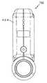
「真の」7番目の軸を有する測定プローブを用いることが望ましい場合には、すなわち、測定プローブが、旋回回転を測定するための7番目の回転エンコーダを備えており、そのような測定プローブを、図30〜図33に示す。これらの図面には、測定プローブ500が図示されており、そのような測定プローブは、図27の測定プローブと実質的に同様であって、主な違いは、上述したタイプのモジュール式の軸受/変換器カートリッジ502を装着していること、測定プローブの側面に捕捉スイッチ504および確認スイッチ506があること、脱着可能なハンドル508を含むことである。 If it is desirable to use a measuring probe with a “true” seventh axis, ie the measuring probe comprises a seventh rotary encoder for measuring the swivel rotation, 30 to 33. In these drawings, a
言うまでもないが、モジュール式の軸受/変換器カートリッジ502は、詳細に上述したカートリッジと実質的に同様であって、回転可能なシャフトと、シャフト上の一対の軸受と、光学エンコーダディスクと、エンコーダディスクから間隔をあけて配置されて、エンコーダディスクと光学的な通信状態にある、少なくとも1つ、望ましくは、2つの光学読み取りヘッドと、これらの、軸受と、光学エンコーダディスクと、読み取りヘッドと、シャフトの少なくとも一部と、を取り囲むハウジングと、を含んでおり、単体のモジュール式の軸受/変換器カートリッジを画定することになる。エンコーダ電子回路のための回路基板503が、プローブ500の開口504にある。捕捉ボタン504および確認ボタン506の各対は、プローブ500の下向きに突き出たハウジング部分510のいずれの側面にも配置されており、各ボタンは、図27の実施の形態による測定プローブにおいてと同様に、適切なPC基板512に接続されている。同様に、表示灯513が、上述した実施の形態においてと同様に、ボタン504とボタン506との間に配置されている。ハウジング510におけるねじ切りされた一対の開口514において、測定プローブ500の使用中に容易に回転操作することを可能にするハンドル508を脱着可能に連結するための固定具を収容する。 It goes without saying that the modular bearing /
その他の重要な全ての点において、測定プローブ500は、図27の測定プローブ28と同様であって、望ましくは、516に、恒久的に取り付けられたタッチトリガプローブを用いるとともに、タッチトリガプローブを保護しつつ固定プローブ518を適応させるための脱着可能なキャップを用いる。言うまでもないが、測定プローブ500に7番目の回転エンコーダ502が含まれていると、CMM10を、既に知られているラインレーザスキャナおよびその他の周辺機器と接続して用いる上で役に立つ。 In all other important respects,
次に、図2〜図4、図23および図25を参照すると、本発明の重要な特徴によれば、携帯可能な電力供給装置を設けて、CMM10に電力を供給することで、完全に携帯可能なCMMが提供される。これは、従来のCMMにおいて、電力供給を、ACコードのみによって得ていたのとは異なる。また、CMM10は、通常の差し込み式のコンセントからAC/DCアダプタを介してACコードによって直接、電力供給を得るようにしてもよい。図2、図3および図25に示すように、通常の再充電可能な電池(例えば、リチウムイオン電池)が、22に図示されている。電池22は、通常の電池支持部252に機械的かつ電気的に接続されており、これは、さらに、回路基板20上に配置された通常の電力供給用および電池再充電用の回路部品254に電気的に接続されている。同様に、基板20と通信を行うのは、オン/オフスイッチ258(図3参照)および高速通信ポート260(望ましくは、USBポート)である。アーム14のジョイント電子回路は、RS−485バスを用いて基板20に接続されている。電池22は、独立した充電器上で充電したり、通常のビデオカメラで一般的にみられるようにクレードル252における所定の位置に入れて充電したりすることが可能である。言うまでもないが、携帯可能なコンピュータ172(図2参照)は、その内蔵電池により数時間にわたって動作することが可能であり、および/または、代替的に、CMM10の電力供給ユニット254に電気的に接続される場合もある。 2-4, 23, and 25, according to an important feature of the present invention, a portable power supply device is provided to supply power to the
本発明によるオンボード電力供給/再充電ユニットは、望ましくは、この部品を、基部12の一体化された部分として、より具体的には、プラスチック製の基部ハウジング26A,26Bの一部として配置することによって、CMM10の一体化された部分として配置される。なお、望ましくは、基部ハウジング26A,26Bは、予備の電池またはプローブ等を保管するために、枢動可能な蓋262を有する小型の保管領域259を含む。 The on-board power supply / recharge unit according to the present invention desirably places this component as an integral part of the
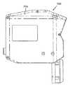
次に、図34Aおよび図34Bを参照すると、ラインレーザスキャナ312が図示されており、これは、プローブ28,28’,232上に、より望ましくは、プローブ500上に完全に一体化されている。ラインレーザスキャナ312には、デジタルカメラ316と、ラインレーザ318と、適切な電子回路320と、を収容するためのハウジング314が含まれる。ハウジング314は、プローブ28を取り囲んでおり、そこから下向きに延在するハンドル322を含む。ハンドル322は、レーザスキャナを使用する際に、操作者によって、容易にアクセス可能(accessible)となっている。重要なことは、レーザスキャナは、正確な、オンラインの測定を確実にするように回転可能であるべきであるということである。そのために、ハウジング312は、適切な軸受構造324を用いて、追加の(すなわち、7番目の)回転軸に取り付けられる。この好適な実施の形態において、この追加の回転軸は、変換器を含むので、多関節アーム14において、通常、5つまたは6つのジョイントに加えて、完全に独立したジョイントを構成する。より望ましくは、追加の軸は、アームの3軸リスト(手首)の一部である(これは、一般的な2−1−3または2−2−3のアーム構成につながる)。 Referring now to FIGS. 34A and 34B, a
望ましくは、図27および図28A〜図28Cに示したような一体化されたタッチプローブおよびハードプローブカバーの連結機構は、図34Aおよび図34Bの実施の形態においても同様に用いられる。一体化されたラインレーザスキャナ312は、既に知られている通常のやり方で動作することになるが、携帯可能なCMMの端部に後付けしなければならない従来の機器とは異なり、本発明は、CMMに、完全に一体化されている。従って、電子回路320は、多関節アーム14における電力および信号のためのバスに完全に一体化されることになる。その結果、レーザスキャナおよびCMMプローブは、同一のハウジング内に配置されて、同一の内部配線を用いて、統合された機械的な構造を構成することになる。また、このような構造によれば、同時に、レーザスキャナと、タッチプローブまたはハードプローブと、を用いたり、これらにアクセスしたりということが可能になる。さらに、回路320によれば、ホストコンピュータ172と連係するときに、即時、かつ、レーザスキャナからの信号がRS−485(または、同様の)シリアル通信バスを介して送信されている操作しやすい環境において、基板上における画像分析および画像処理が行われることになる。 Preferably, the integrated touch probe and hard probe cover coupling mechanism as shown in FIGS. 27 and 28A-28C is used in the embodiment of FIGS. 34A and 34B as well. The integrated
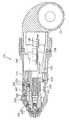
一体化されたラインレーザスキャナのもう1つの実施の形態が、図35〜図39に図示されており、図中、CMM10は、一体化されたラインレーザスキャナ/プローブ600が、プローブ28に連結されている状態で図示されている。図36および図37に示すように、プローブ28から間隔をあけて離して配置されているのは、レーザ放出窓であり、これを通じて、走査レーザビーム604が、走査レーザ601から放出される。走査レーザ604は、スキャナ/プローブ600の平面図を示す図37の紙面に平行に、図36の紙面に垂直に位置する面を横切って走査する。レーザ放出窓602の下方には、CCD窓606がある。CCD窓606は、実際のところ、ハウジング610の内部に配置されたCCD605の集束レンズであろうが、これについては、以下に、さらに詳細に説明することとする。CCD605は、図中、破線608で示すような視界(FOV:Field of View)を有する。CCD605のFOVは、図37において破線で示した領域612の範囲内において走査レーザビーム604によって画定された面と交差する。従って、言うまでもないが、ある物体を、領域612を通過させた場合に、スキャナ/プローブ600の方に面している、その物体上における領域612に交差する点の軌跡は、走査レーザビーム604によって照射されて、CCD605によって撮像されることになる。 Another embodiment of an integrated line laser scanner is illustrated in FIGS. 35-39, in which the
走査レーザビーム604によって照射された物体の点の軌跡は、CCD605上において外形画像として現れることになる。ラインレーザスキャナ/プローブ600の位置および向きは、CMM10において分かっているので、走査レーザビーム604によって画定された面における領域612の正確な位置は分かっている。そのビームによって照射された物体上の点が、ラインレーザスキャナ/プローブ600に近づけられたり遠ざけられたりすると、レーザによって反射された光の画像が、CCD撮像面(図示せず)上において寄ったり引いたりするが、このとき、CCD605の撮像面上における左側の点および右側の点は、領域612に交差する物体であって、走査レーザビーム604によって照射された物体の左側の位置および右側の位置に対応する。従って、CCD605における各々の画素は、CCD605のFOVの範囲内であって、走査レーザビーム604によって照射される可能性がある領域612において対応する位置と対応付けられている。 The locus of the point of the object irradiated by the
図38および図39を参照すると、CCD605からの画像データが、ハウジング610のハンドル611内における回路基板である画像処理基板620上において処理される。CCD605は、CCD605によって検出された画像を取り込んで、これを、例えば、アップルコンピュータ社(Apple Computers, Inc.)によって確立されたファイヤワイヤ(FIREWIRE)データ形式(または、いずれかの好適な高速データ通信プロトコル)のような、デジタル形式に変換するためのセンサ基板を含む。完全な画像は、新規な画像処理基板620に即座に中継される。画像処理基板620は、ファイヤワイヤインターフェース622と、デジタル信号プロセッサ(DSP)624と、メモリ626と、を含む。DSPが画像データを受信すると、これは、それを即座に処理する。ソフトウェアアルゴリズムによって、各フレームを処理して、測定された物体の正確な位置をサブピクセル精度で特定する。これが可能であるのは、ラインレーザを横切る輪郭(profile)が、ガウス関数に近似しており、CCD画像面上における複数行の画素を横切って広がるからである。ライン位置に相当する適切な画素を選択することは、そのソフトウェアの重要な機能である。ソフトウェアアルゴリズムによって、1つの画素列に沿ったライン輪郭を分析して、「重心(COV:Center of Gravity)」を算出すると、これは、部分画素位置であることも可能であり、そのラインの厳密な位置を最適に表す点となる。 Referring to FIGS. 38 and 39, the image data from the
アルゴリズムは、続いて、フレーム内の各々の列についてCOVを算出する。そのフレームが処理された後は、元の画像は廃棄されて、処理済みデータのみが保持される。保持された情報は、各々のジョイントにある様々なデジタルエンコーダによって生成されたその他のデータと同様に、CMMの基部にある基板に、通信チップ627を介して送信される。画像処理基板620によって生成されたデータパケットは、元の画像サイズのほんの何分の一かのサイズであって、かなりの量の通信帯域幅が必要とされるということはない。メインCMMプロセッサからは、そのデータが、そのときのアーム位置とともにホストCPUに送信される。このように、この新規な画像処理基板によれば、アーム10内におけるオンボード画像処理が可能となるが、これは、そのような画像処理を、独立したユニットまたはレーザスキャナに外部の後付け部品を介して配線接続されたコンピュータにおいて実現する従来の技術とは対照的である。 The algorithm then calculates the COV for each column in the frame. After the frame is processed, the original image is discarded and only the processed data is retained. The retained information is transmitted via the
上述した実施の形態においてと同様に、ハンドル611は、2つのスイッチ、すなわち、捕捉スイッチ200および確認スイッチ202を含む。これらのスイッチを操作者がプローブ検出モード時に用いて、操作中に、測定値を捕捉(捕捉スイッチ200)するとともに、その測定値を確認(確認スイッチ202)する。また、表示灯204が、正常なプローブ検出が行われていることを表示するために、スイッチ200,202と対応付けられている。望ましくは、表示灯204は、2色灯であり、例えば、灯204は、測定値を捕捉(緑色の捕捉ボタン200を押下)しているときは緑色であって、測定値を確認(赤色の確認ボタン202を押下)している間は赤色である。多色灯を用いることは、既に知られているLEDを灯204の光源として用いることで容易に達成される。 As in the embodiment described above, the
走査モード時においては、捕捉スイッチ200によって、上述した走査プロセスを作動させる一方で、確認スイッチ202をその他の何らかの目的で、例えば、直前の走査を取り消すために用いるようにしてもよい。いずれのモードであっても、各スイッチの機能については、ソフトウェアプログラムによって指定することができる。 In the scan mode, the
図38のプローブ28は、図27および図30において上述したように、タッチプローブ機構210およびハードプローブカバー220を含む。タッチプローブ機構210は、スプリングによってバイアスがかけられた要素に接触するノーズ212を備える。3つのコンタクトピンが、下にある電気回路と接触している。プローブノーズ212に対して力を加えると、結果として、3つのコンタクトピンの1つを持ち上げることになり、下にある電気回路を開くことになり、従って、スイッチを作動させることになる。望ましくは、タッチトリガプローブ210は、プローブモード時において、前面の「捕捉」スイッチ200と連係して動作することになる。 The
タッチプローブ機構210を用いる場合に、プローブカバー220が、螺合状態から取り外される。但し、タッチトリガプローブではなく、固定プローブを用いるのが望ましい場合には、プローブカバー220が、図示のように連結される。言うまでもないが、プローブカバー220は、これに連結された球状のボール226を有するが、どのような異なる所望の固定プローブ構造であっても、容易に、プローブ28に螺合可能に連結することができる。タッチプローブ機構210は、ハウジング228に取り付けられており、これは、ねじ切りされたコネクタに螺合可能に収容されており、これによって、プローブハウジング110の一部が形成される。 When the
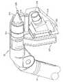
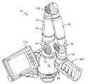
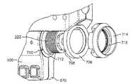
次に、図40〜図48を参照すると、ラインレーザスキャナのさらにもう1つの実施の形態が、700に図示されている。図40において、レーザスキャナ700は、図30〜図32に示したタイプのプローブ500を有するCMM702に連結された状態で図示されている。図47を参照すると、レーザスキャナ700は、ハウジング704を含んでおり、これに、CCD窓606と、集束レンズ605と、画像処理基板620と、高速データ通信プロトコルインターフェース基板622と、デジタル信号プロセッサ624と、メモリ626と、を収容するが、これらの全てについては、既に、図38の実施の形態と関連して上述している。 With reference now to FIGS. 40-48, yet another embodiment of a line laser scanner is illustrated at 700. In FIG. 40, a
ハウジング704から外向きおよび下向きに延在しているのは、キネマティックリングであり、これは、図49および図50に最適に図示されており、これには、間隔をあけて(望ましくは、等間隔つまり180°ずつ隔てて)配置された3つの切り欠きまたは開口707が含まれる。各々の開口707には、そのなかに小型の円筒形棒材708を収容する。円筒形棒材708は、プローブ500の下向きに突き出たハウジング部分510の内部表面712上に、対応するように間隔をあけて配置された、相補的な形状の開口710に収容される。保持リング714には、内ねじ切り716を備えており、これが、プローブ500のねじ切り222に螺合可能に収容されて、さらに、これが、ハウジング504をしっかりとプローブ500に正確な位置合わせで接続する(キネマティックシート706による)。 Extending outwardly and downwardly from
レーザスキャナ700は、図38のレーザスキャナ600の場合と同様に動作するが、スキャナ700には、追加軸プローブ500に、容易に、脱着可能に連結可能であるという利点がある(これは、図24Aおよび図38の、より恒久的に連結されたレーザスキャナと対照的である)。上述したレーザスキャナの実施の形態と同様に、図40〜図48のラインレーザスキャナは、完全に一体化された走査機器を提供しており、これは、ラインレーザと、光学フィルタと、デジタルカメラと、で構成されており、これらの全てが、画像分析および3次元分析のために、高速データ通信プロトコル(すなわち、ファイヤワイヤ)からデジタル画像に処理するプロセッサ、DSPプロセッサ、およびメモリに接続されており、最後に、結果として得られるデータパケットを、CMM10の多関節アームのバスに通信するために通信プロセッサに接続されており、最終的には、ホストコンピュータ172に接続されている。重要なこととしては、レーザスキャナ700は、CMM10のアームに既に組み込まれている電力供給装置を用いることになる。この実施の形態において必要なただ1つの外部ケーブルは、スキャナハウジング704からプローブ500上のコネクタへのショートケーブルである。このケーブルは、データパケットを送信するために、電力および信号のためのバス接続を媒介する。ホストCPU172との通信手段は、多関節アームの内部に組み込まれているので、従来の機器と同様に、外部通信ケーブルは必要ない。従って、本発明のレーザスキャナによれば、内部デジタル画像化プロセッサ基板620が画像化センサデータを即座に分析することが可能となり、そのような分析の結果は、ホストCPUに、そのときのエンコーダ位置データとともに通信して戻される。上述したように、従来の技術では、煩雑で、かさばる外部ケーブルを含んだ外部ビデオ処理ユニットおよび電力供給装置が必要とされる。 The
スキャナ700のもう1つの特徴によれば、レーザ602とカメラ605との間に固定的な、熱的に安定した配置(rigid thermal and stable orientation)があって、ハウジング704と追加軸プローブ500との間に熱的に安定した接続があることが重要である。そのために、好適な実施の形態によれば、ハウジング704内におけるフレーム718の内部構造は、熱膨張係数(CTE:Coefficient of Thermal Expansion)が低い材料(例えば、平均CTEが、1.0×10⁻⁶〜10×10-6 in/in/°Fの間である材料)、望ましくは、例えば、スチール/ニッケル合金のような金属合金、例えば、インバー(望ましくは、インバー36)でつくられている。この金属フレーム718は、通常、プラスチック製のハウジング704の範囲内にとどまることなく、連結リング706として延在しており、上述した3点キネマティックマウントに直接に接続することを可能にする。上述したように、3点キネマティックマウント710は、スキャナハウジング704を収容するために、アームのプローブマウントの基部に配置されている。さらに、言うまでもないが、キネマティックマウント710は、必要に応じて、どのようなその他の外部に取り付けられたセンサを収容するようにしてもよい。According to another feature of the
図34〜図48のレーザスキャナは、本明細書に記載のCMMに用いることができるにすぎないというわけではなく、例えば、上述の米国特許第5,794,356号明細書または米国特許第5,829,148号明細書に記載のような多関節アームを有するその他のどのような携帯可能なCMMに用いてもよいし、コサカ(Kosaka)社、シムコア(Cimcore)社、ローマー(Romer)社、他によって製造された多関節CMMアームに用いてもよい。 The laser scanners of FIGS. 34-48 can only be used in the CMM described herein, for example, the above-mentioned US Pat. No. 5,794,356 or US Pat. , 829,148 and any other portable CMM having an articulated arm, Kosaka, Simcore, Romer , May be used for articulated CMM arms manufactured by others.
いくつかの好適な実施の形態を図示および説明してきたが、本発明の精神および範囲から逸脱することなく、これらに対して、様々な修正および置換を行うことが可能である。従って、当然のことながら、本発明は、限定としてではなく、例示として説明されたものである。 While several preferred embodiments have been shown and described, various modifications and substitutions can be made thereto without departing from the spirit and scope of the present invention. Accordingly, it is to be understood that the present invention has been described by way of illustration and not limitation.
Claims (23)
Translated fromJapanese対向する第1および第2の端部を有する手動で位置決め可能な多関節アームであって、前記アームが、複数のジョイントアーム部分を含み、各々のアーム部分が、位置信号を生成するための少なくとも1つの位置変換器を含む多関節アームと、
前記アームの前記第1の端部に取り付けられ、球状のボールを有するプローブと、
前記プローブに軸受を介して接続され、前記軸受により前記球状のボールを通る軸と同軸に回転可能であるとともに、前記球状のボールを通る軸を中心にした回転を測定する回転エンコーダを有するレーザスキャナと、
前記変換器から前記位置信号を受信して、選択された量で、前記球状のボールの位置に対応するデジタル座標を提供するとともに、前記回転エンコーダの測定結果に基づいて前記レーザスキャナに対応するデジタル座標を提供する電子回路と、
電力信号およびデータ信号のうちの少なくとも1つを前記レーザスキャナに伝送するための前記多関節アーム内における少なくとも1つのバスと、
を備えており、前記レーザスキャナが、前記少なくとも1つのバスと通信を行う回路を含むCMM。A portable coordinate measuring device (CMM) that measures the position of an object by a selected amount,
A manually positionable articulated arm having opposing first and second ends, the arm including a plurality of joint arm portions, each arm portion at least for generating a position signal An articulated arm including one position transducer;
A probeattached to the first end of the armand having a spherical ball ;
A laser scannerhaving a rotary encoderconnected to the probevia a bearing and capableof rotatingcoaxially with anaxis passing through the spherical ball by the bearingand measuring rotation about the axis passing through the spherical ball When,
Receiving the position signal from the transducer and providing digital coordinates corresponding to the position of thespherical ball in a selected amount and corresponding to thelaser scanner based on the measurement result of the rotary encoder; An electronic circuitthat provides coordinates ;
At least one bus in the articulated arm for transmitting at least one of a power signal and a data signal to the laser scanner;
And the laser scanner includes a circuit for communicating with the at least one bus.
前記レーザスキャナが、さらに、
カメラと、
カメラにより検出された画像を処理する画像処理基板と、
を備えるCMM。The CMM of claim 1,
The laser scanner further comprises:
A camera,
An image processing board for processing an image detected by the camera;
CMM with
前記画像処理基板は、
前記カメラと通信を行うデジタルインターフェースと、
前記スキャナからの画像を処理するために、前記デジタルインターフェースと通信を行うデジタル信号プロセッサ(DSP)と、
前記DSPと通信を行うメモリと、
前記DSPと通信を行う通信プロセッサと、
を備えるCMM。The CMM of claim 18, comprising:
The image processing substrate is:
A digital interface for communicating with the camera;
A digital signal processor (DSP) in communication with the digital interface to process an image from the scanner;
A memory for communicating with the DSP;
A communication processor for communicating with the DSP;
CMM with
Applications Claiming Priority (3)
| Application Number | Priority Date | Filing Date | Title |
|---|---|---|---|
| US35759902P | 2002-02-14 | 2002-02-14 | |
| US39490802P | 2002-07-10 | 2002-07-10 | |
| PCT/US2003/004289WO2003069277A1 (en) | 2002-02-14 | 2003-02-13 | Portable coordinate measurement machine with integrated line laser scanner |
Publications (2)
| Publication Number | Publication Date |
|---|---|
| JP2005517914A JP2005517914A (en) | 2005-06-16 |
| JP4576002B2true JP4576002B2 (en) | 2010-11-04 |
Family
ID=27737606
Family Applications (3)
| Application Number | Title | Priority Date | Filing Date |
|---|---|---|---|
| JP2003568342APendingJP2005517909A (en) | 2002-02-14 | 2003-02-13 | Portable coordinate measuring instrument with articulated arm |
| JP2003568352AExpired - Fee RelatedJP4576002B2 (en) | 2002-02-14 | 2003-02-13 | Portable coordinate measuring device with built-in line laser scanner |
| JP2003568341APendingJP2005517908A (en) | 2002-02-14 | 2003-02-13 | Articulated arm for portable coordinate measuring instrument |
Family Applications Before (1)
| Application Number | Title | Priority Date | Filing Date |
|---|---|---|---|
| JP2003568342APendingJP2005517909A (en) | 2002-02-14 | 2003-02-13 | Portable coordinate measuring instrument with articulated arm |
Family Applications After (1)
| Application Number | Title | Priority Date | Filing Date |
|---|---|---|---|
| JP2003568341APendingJP2005517908A (en) | 2002-02-14 | 2003-02-13 | Articulated arm for portable coordinate measuring instrument |
Country Status (8)
| Country | Link |
|---|---|
| US (13) | US6935036B2 (en) |
| EP (3) | EP1474653B1 (en) |
| JP (3) | JP2005517909A (en) |
| CN (3) | CN100523709C (en) |
| AT (2) | ATE382845T1 (en) |
| AU (3) | AU2003223173A1 (en) |
| DE (2) | DE60314598T2 (en) |
| WO (3) | WO2003069267A1 (en) |
Families Citing this family (254)
| Publication number | Priority date | Publication date | Assignee | Title |
|---|---|---|---|---|
| GB9515311D0 (en) | 1995-07-26 | 1995-09-20 | 3D Scanners Ltd | Stripe scanners and methods of scanning |
| US6952882B2 (en) | 2002-02-14 | 2005-10-11 | Faro Technologies, Inc. | Portable coordinate measurement machine |
| US7246030B2 (en) | 2002-02-14 | 2007-07-17 | Faro Technologies, Inc. | Portable coordinate measurement machine with integrated line laser scanner |
| US7519493B2 (en) | 2002-02-14 | 2009-04-14 | Faro Technologies, Inc. | Portable coordinate measurement machine with integrated line laser scanner |
| US7073271B2 (en)* | 2002-02-14 | 2006-07-11 | Faro Technologies Inc. | Portable coordinate measurement machine |
| US7881896B2 (en) | 2002-02-14 | 2011-02-01 | Faro Technologies, Inc. | Portable coordinate measurement machine with integrated line laser scanner |
| AU2003223173A1 (en) | 2002-02-14 | 2003-09-04 | Faro Technologies, Inc. | Portable coordinate measurement machine with integrated line laser scanner |
| US6973734B2 (en) | 2002-02-14 | 2005-12-13 | Faro Technologies, Inc. | Method for providing sensory feedback to the operator of a portable measurement machine |
| US6957496B2 (en) | 2002-02-14 | 2005-10-25 | Faro Technologies, Inc. | Method for improving measurement accuracy of a portable coordinate measurement machine |
| USRE42082E1 (en) | 2002-02-14 | 2011-02-01 | Faro Technologies, Inc. | Method and apparatus for improving measurement accuracy of a portable coordinate measurement machine |
| DE60306902T2 (en)* | 2002-02-26 | 2007-01-11 | Faro Technologies, Inc., Lake Mary | STANDARD VACUUM ADAPTER |
| AU2003282242A1 (en)* | 2002-11-15 | 2004-06-15 | Alan George Rock | Level, angle and distance measuring device |
| JP4707306B2 (en)* | 2003-02-28 | 2011-06-22 | 株式会社小坂研究所 | Articulated coordinate measuring device |
| US7257248B2 (en)* | 2003-03-27 | 2007-08-14 | General Electric Company | Non-contact measurement system and method |
| CA2522097C (en) | 2003-04-28 | 2012-09-25 | Stephen James Crampton | Cmm arm with exoskeleton |
| US7672810B2 (en)* | 2003-10-15 | 2010-03-02 | 3D Scanners Ltd. | Method, device and computer program for evaluating an object using a virtual representation of said object |
| FR2861843B1 (en) | 2003-10-29 | 2006-07-07 | Romain Granger | CONNECTING DEVICE ASSOCIATED WITH A THREE DIMENSIONAL MEASURING APPARATUS ARM WITH ARTICULATED ARMS |
| JP4481137B2 (en)* | 2003-11-13 | 2010-06-16 | アスモ株式会社 | Motor, rotation control device, and rotation detection circuit |
| US7152456B2 (en) | 2004-01-14 | 2006-12-26 | Romer Incorporated | Automated robotic measuring system |
| US7693325B2 (en) | 2004-01-14 | 2010-04-06 | Hexagon Metrology, Inc. | Transprojection of geometry data |
| US7508971B2 (en)* | 2004-05-28 | 2009-03-24 | The Boeing Company | Inspection system using coordinate measurement machine and associated method |
| US7253908B2 (en)* | 2004-07-22 | 2007-08-07 | The Boeing Company | Non-destructive inspection using laser profiling and associated method |
| US7165453B2 (en)* | 2004-07-23 | 2007-01-23 | Electric Power Research Institute | Flexible electromagnetic acoustic transducer sensor |
| KR100865056B1 (en)* | 2004-07-26 | 2008-10-23 | 일렉트릭 파워 리서치 인스티튜트, 인크. | Measurement device |
| GB0424729D0 (en)* | 2004-11-09 | 2004-12-08 | Crampton Stephen | Probe end module for articulated arms |
| US7222543B2 (en)* | 2004-11-23 | 2007-05-29 | Dr. Johannes Heidenhain Gmbh | Modular encoder, method of producing a modular encoder, and system for measuring angular movement |
| US7167252B2 (en)* | 2004-11-23 | 2007-01-23 | Kevin Gallup | Method and apparatus for creating cavities in packaging materials for artifacts, art objects and fragile or other valuable items |
| WO2006093899A2 (en) | 2005-02-28 | 2006-09-08 | Electric Power Research Institute, Inc. | Method for inspection and repair |
| US7333219B2 (en)* | 2005-03-29 | 2008-02-19 | Mitutoyo Corporation | Handheld metrology imaging system and method |
| FR2884910B1 (en)* | 2005-04-20 | 2007-07-13 | Romer Sa | THREE-DIMENSIONAL MEASURING APPARATUS WITH ARTICULATED ARMS COMPRISING A PLURALITY OF JOINT AXES |
| EP2202482A1 (en)* | 2005-06-23 | 2010-06-30 | Faro Technologies, Inc. | Apparatus and method for relocating an articulating-arm coordinate measuring machine |
| WO2007017235A2 (en)* | 2005-08-08 | 2007-02-15 | 3D Scanners Ltd | Cmm arm with enhanced manual control |
| GB0516276D0 (en)* | 2005-08-08 | 2005-09-14 | Crampton Stephen | Robust cmm arm with exoskeleton |
| WO2007033273A2 (en)* | 2005-09-13 | 2007-03-22 | Romer Incorporated | Vehicle comprising an articulator of a coordinate measuring machine |
| FR2892034A1 (en)* | 2005-10-14 | 2007-04-20 | Soudure Autogene Francaise Sa | ARC WELDING STATION WITH DATA MASS STORAGE MEMORY |
| US8142528B2 (en)* | 2005-11-30 | 2012-03-27 | General Electric Company | Methods and systems of reducing viscosity of gasification system slag |
| DE202006005643U1 (en)* | 2006-03-31 | 2006-07-06 | Faro Technologies Inc., Lake Mary | Device for three-dimensional detection of a spatial area |
| US7568293B2 (en)* | 2006-05-01 | 2009-08-04 | Paul Ferrari | Sealed battery for coordinate measurement machine |
| US7805854B2 (en) | 2006-05-15 | 2010-10-05 | Hexagon Metrology, Inc. | Systems and methods for positioning and measuring objects using a CMM |
| DE102006031580A1 (en) | 2006-07-03 | 2008-01-17 | Faro Technologies, Inc., Lake Mary | Method and device for the three-dimensional detection of a spatial area |
| CN101529211B (en)* | 2006-08-21 | 2011-12-21 | Gsi集团公司 | Rotary Optical Encoder Using Multiple Sub-Encoders With Common Grazed Substrate |
| US8006399B2 (en)* | 2006-09-05 | 2011-08-30 | Renishaw Plc | Surface sensing device |
| GB0617344D0 (en)* | 2006-09-05 | 2006-10-11 | Renishaw Plc | Surface sensing device |
| US7439713B2 (en)* | 2006-09-20 | 2008-10-21 | Pratt & Whitney Canada Corp. | Modulation control of power generation system |
| EP2092269B1 (en)* | 2006-11-20 | 2019-05-01 | Hexagon Technology Center GmbH | Coordinate measurement machine with improved joint |
| US7784194B2 (en)* | 2006-11-30 | 2010-08-31 | Faro Technologies, Inc. | Portable coordinate measurement machine |
| WO2008080142A1 (en)* | 2006-12-22 | 2008-07-03 | Romer, Inc. | Improved joint axis for coordinate measurement machine |
| US20080189072A1 (en)* | 2007-02-01 | 2008-08-07 | Nescom Inc. | High resolution encoder within a swivel |
| WO2008121073A1 (en)* | 2007-04-03 | 2008-10-09 | Hexagon Metrology Ab | Method and device for exact measurement of objects |
| US9545009B2 (en) | 2007-05-23 | 2017-01-10 | Spectra Logic, Corporation | Passive alterable electrical component |
| WO2008154408A1 (en)* | 2007-06-06 | 2008-12-18 | Tobey Wayland E | Modular hybrid snake arm |
| US7546689B2 (en)* | 2007-07-09 | 2009-06-16 | Hexagon Metrology Ab | Joint for coordinate measurement device |
| DE102007032538B4 (en)* | 2007-07-12 | 2015-03-26 | Siemens Aktiengesellschaft | Medical diagnostic and / or intervention device |
| US8457790B2 (en)* | 2007-09-14 | 2013-06-04 | Zimmer, Inc. | Robotic calibration method |
| EP2037214A1 (en) | 2007-09-14 | 2009-03-18 | Leica Geosystems AG | Method and measuring device for measuring surfaces |
| US7774949B2 (en)* | 2007-09-28 | 2010-08-17 | Hexagon Metrology Ab | Coordinate measurement machine |
| US7797849B2 (en)* | 2007-10-31 | 2010-09-21 | Immersion Corporation | Portable metrology device |
| JP2009122066A (en)* | 2007-11-19 | 2009-06-04 | Mitsutoyo Corp | Non-contact three-dimensional measurement method and device thereof |
| EP2068124A1 (en) | 2007-12-04 | 2009-06-10 | Metris IPR N.V. | Articulated arm measuring machine endowed with multiple measurement disks |
| US8122610B2 (en)* | 2008-03-28 | 2012-02-28 | Hexagon Metrology, Inc. | Systems and methods for improved coordination acquisition member comprising calibration information |
| US7779548B2 (en)* | 2008-03-28 | 2010-08-24 | Hexagon Metrology, Inc. | Coordinate measuring machine with rotatable grip |
| EP2108917B1 (en) | 2008-04-07 | 2012-10-03 | Leica Geosystems AG | Articulated arm coordinate measuring machine |
| USD599226S1 (en) | 2008-04-11 | 2009-09-01 | Hexagon Metrology, Inc. | Portable coordinate measurement machine |
| US7640674B2 (en)* | 2008-05-05 | 2010-01-05 | Hexagon Metrology, Inc. | Systems and methods for calibrating a portable coordinate measurement machine |
| US8035823B2 (en)* | 2008-09-05 | 2011-10-11 | 3Dm Devices Inc. | Hand-held surface profiler |
| US7908757B2 (en) | 2008-10-16 | 2011-03-22 | Hexagon Metrology, Inc. | Articulating measuring arm with laser scanner |
| US9482755B2 (en) | 2008-11-17 | 2016-11-01 | Faro Technologies, Inc. | Measurement system having air temperature compensation between a target and a laser tracker |
| EP2194357A1 (en) | 2008-12-03 | 2010-06-09 | Leica Geosystems AG | Optical sensor element for a measuring device and coupling element for this containing measuring device unit |
| US8176809B2 (en)* | 2008-12-10 | 2012-05-15 | GM Global Technology Operations LLC | Planar torsion spring |
| DE102008062624A1 (en)* | 2008-12-17 | 2010-06-24 | Kuka Roboter Gmbh | Hand-held device and method for detecting the spatial position of an operating point of a manipulator |
| US7983790B2 (en)* | 2008-12-19 | 2011-07-19 | The Boeing Company | Component repair using reverse engineering |
| DE102009010465B3 (en)* | 2009-02-13 | 2010-05-27 | Faro Technologies, Inc., Lake Mary | laser scanner |
| DE102009015920B4 (en) | 2009-03-25 | 2014-11-20 | Faro Technologies, Inc. | Device for optically scanning and measuring an environment |
| US9551575B2 (en) | 2009-03-25 | 2017-01-24 | Faro Technologies, Inc. | Laser scanner having a multi-color light source and real-time color receiver |
| US8082673B2 (en) | 2009-11-06 | 2011-12-27 | Hexagon Metrology Ab | Systems and methods for control and calibration of a CMM |
| WO2010116203A1 (en)* | 2009-04-06 | 2010-10-14 | Aktiebolaget Skf | Detection system, joint system provided with such a detection system and automotive vehicle equipped with such a joint system |
| DE102009017581B4 (en)* | 2009-04-18 | 2021-06-24 | Igus Gmbh | Multi-axis joint especially for robotics |
| US8423190B1 (en)* | 2009-06-11 | 2013-04-16 | Kabushiki Kaisha Yaskawa Denki | Manipulator system |
| US8104189B2 (en)* | 2009-06-30 | 2012-01-31 | Hexagon Metrology Ab | Coordinate measurement machine with vibration detection |
| DE102009031712A1 (en) | 2009-07-04 | 2011-08-04 | Schaeffler Technologies GmbH & Co. KG, 91074 | Bearing cartridge, in particular for the articulated arm of a three-dimensional coordinate measuring device |
| DE102009035336B3 (en) | 2009-07-22 | 2010-11-18 | Faro Technologies, Inc., Lake Mary | Device for optical scanning and measuring of environment, has optical measuring device for collection of ways as ensemble between different centers returning from laser scanner |
| DE102009035337A1 (en) | 2009-07-22 | 2011-01-27 | Faro Technologies, Inc., Lake Mary | Method for optically scanning and measuring an object |
| US20110285981A1 (en)* | 2010-05-18 | 2011-11-24 | Irvine Sensors Corporation | Sensor Element and System Comprising Wide Field-of-View 3-D Imaging LIDAR |
| ES2511869T3 (en)* | 2009-10-22 | 2014-10-23 | Abb Research Ltd. | Robot part and method to protect a robot part |
| US9529083B2 (en) | 2009-11-20 | 2016-12-27 | Faro Technologies, Inc. | Three-dimensional scanner with enhanced spectroscopic energy detector |
| DE102009057101A1 (en) | 2009-11-20 | 2011-05-26 | Faro Technologies, Inc., Lake Mary | Device for optically scanning and measuring an environment |
| US9113023B2 (en) | 2009-11-20 | 2015-08-18 | Faro Technologies, Inc. | Three-dimensional scanner with spectroscopic energy detector |
| DE102009055988B3 (en) | 2009-11-20 | 2011-03-17 | Faro Technologies, Inc., Lake Mary | Device, particularly laser scanner, for optical scanning and measuring surrounding area, has light transmitter that transmits transmission light ray by rotor mirror |
| US9210288B2 (en) | 2009-11-20 | 2015-12-08 | Faro Technologies, Inc. | Three-dimensional scanner with dichroic beam splitters to capture a variety of signals |
| DE102009055989B4 (en) | 2009-11-20 | 2017-02-16 | Faro Technologies, Inc. | Device for optically scanning and measuring an environment |
| US20110213247A1 (en)* | 2010-01-08 | 2011-09-01 | Hexagon Metrology, Inc. | Articulated arm with imaging device |
| US8630314B2 (en) | 2010-01-11 | 2014-01-14 | Faro Technologies, Inc. | Method and apparatus for synchronizing measurements taken by multiple metrology devices |
| WO2011090895A1 (en)* | 2010-01-20 | 2011-07-28 | Faro Technologies, Inc. | Portable articulated arm coordinate measuring machine with multi-bus arm technology |
| US8898919B2 (en) | 2010-01-20 | 2014-12-02 | Faro Technologies, Inc. | Coordinate measurement machine with distance meter used to establish frame of reference |
| US8677643B2 (en) | 2010-01-20 | 2014-03-25 | Faro Technologies, Inc. | Coordinate measurement machines with removable accessories |
| US8284407B2 (en) | 2010-01-20 | 2012-10-09 | Faro Technologies, Inc. | Coordinate measuring machine having an illuminated probe end and method of operation |
| US9628775B2 (en) | 2010-01-20 | 2017-04-18 | Faro Technologies, Inc. | Articulated arm coordinate measurement machine having a 2D camera and method of obtaining 3D representations |
| US8942940B2 (en)* | 2010-01-20 | 2015-01-27 | Faro Technologies, Inc. | Portable articulated arm coordinate measuring machine and integrated electronic data processing system |
| US8615893B2 (en) | 2010-01-20 | 2013-12-31 | Faro Technologies, Inc. | Portable articulated arm coordinate measuring machine having integrated software controls |
| US9607239B2 (en) | 2010-01-20 | 2017-03-28 | Faro Technologies, Inc. | Articulated arm coordinate measurement machine having a 2D camera and method of obtaining 3D representations |
| US9163922B2 (en) | 2010-01-20 | 2015-10-20 | Faro Technologies, Inc. | Coordinate measurement machine with distance meter and camera to determine dimensions within camera images |
| US9879976B2 (en) | 2010-01-20 | 2018-01-30 | Faro Technologies, Inc. | Articulated arm coordinate measurement machine that uses a 2D camera to determine 3D coordinates of smoothly continuous edge features |
| US8875409B2 (en) | 2010-01-20 | 2014-11-04 | Faro Technologies, Inc. | Coordinate measurement machines with removable accessories |
| US8832954B2 (en) | 2010-01-20 | 2014-09-16 | Faro Technologies, Inc. | Coordinate measurement machines with removable accessories |
| EP2372302A1 (en) | 2010-03-26 | 2011-10-05 | Leica Geosystems AG | Measuring method for a surface measuring machine |
| USD643319S1 (en) | 2010-03-29 | 2011-08-16 | Hexagon Metrology Ab | Portable coordinate measurement machine |
| DE102010013923A1 (en)* | 2010-04-01 | 2011-10-06 | Wittenstein Ag | Manipulator, particularly robotic palletizer, hinged bracket robot or linear actuator for machine tool, has moving manipulator element, and drive disposed on moving element of manipulator |
| US9772394B2 (en) | 2010-04-21 | 2017-09-26 | Faro Technologies, Inc. | Method and apparatus for following an operator and locking onto a retroreflector with a laser tracker |
| US8537371B2 (en) | 2010-04-21 | 2013-09-17 | Faro Technologies, Inc. | Method and apparatus for using gestures to control a laser tracker |
| US8422034B2 (en) | 2010-04-21 | 2013-04-16 | Faro Technologies, Inc. | Method and apparatus for using gestures to control a laser tracker |
| US8619265B2 (en) | 2011-03-14 | 2013-12-31 | Faro Technologies, Inc. | Automatic measurement of dimensional data with a laser tracker |
| US9377885B2 (en) | 2010-04-21 | 2016-06-28 | Faro Technologies, Inc. | Method and apparatus for locking onto a retroreflector with a laser tracker |
| US9400170B2 (en) | 2010-04-21 | 2016-07-26 | Faro Technologies, Inc. | Automatic measurement of dimensional data within an acceptance region by a laser tracker |
| US8724119B2 (en) | 2010-04-21 | 2014-05-13 | Faro Technologies, Inc. | Method for using a handheld appliance to select, lock onto, and track a retroreflector with a laser tracker |
| US9335160B2 (en) | 2010-04-26 | 2016-05-10 | Nikon Corporation | Profile measuring apparatus |
| DE102010020925B4 (en) | 2010-05-10 | 2014-02-27 | Faro Technologies, Inc. | Method for optically scanning and measuring an environment |
| DE102010017304A1 (en) | 2010-06-09 | 2011-12-15 | Martin Knauer | Coordinate measuring apparatus, method for operating a coordinate measuring apparatus and computer program product |
| US9368046B2 (en) | 2010-07-14 | 2016-06-14 | Macronix International Co., Ltd. | Color tactile vision system |
| DE102010032725B4 (en)* | 2010-07-26 | 2012-04-26 | Faro Technologies, Inc. | Device for optically scanning and measuring an environment |
| DE102010032726B3 (en) | 2010-07-26 | 2011-11-24 | Faro Technologies, Inc. | Device for optically scanning and measuring an environment |
| DE102010032723B3 (en) | 2010-07-26 | 2011-11-24 | Faro Technologies, Inc. | Device for optically scanning and measuring an environment |
| DE102010033561B3 (en) | 2010-07-29 | 2011-12-15 | Faro Technologies, Inc. | Device for optically scanning and measuring an environment |
| US8127458B1 (en)* | 2010-08-31 | 2012-03-06 | Hexagon Metrology, Inc. | Mounting apparatus for articulated arm laser scanner |
| GB2501390B (en) | 2010-09-08 | 2014-08-06 | Faro Tech Inc | A laser scanner or laser tracker having a projector |
| USD676309S1 (en)* | 2010-11-16 | 2013-02-19 | Faro Technologies, Inc. | Base for a device |
| USD662427S1 (en) | 2010-11-16 | 2012-06-26 | Faro Technologies, Inc. | Measurement device |
| US9168654B2 (en) | 2010-11-16 | 2015-10-27 | Faro Technologies, Inc. | Coordinate measuring machines with dual layer arm |
| JP5771286B2 (en) | 2011-01-14 | 2015-08-26 | ファロ テクノロジーズ インコーポレーテッド | Case for equipment |
| GB2503390B (en) | 2011-03-03 | 2014-10-29 | Faro Tech Inc | Target apparatus and method |
| EP2511656A1 (en) | 2011-04-14 | 2012-10-17 | Hexagon Technology Center GmbH | Measuring system for determining the 3D coordinates of an object surface |
| JP2014516409A (en) | 2011-04-15 | 2014-07-10 | ファロ テクノロジーズ インコーポレーテッド | Improved position detector for laser trackers. |
| US9686532B2 (en) | 2011-04-15 | 2017-06-20 | Faro Technologies, Inc. | System and method of acquiring three-dimensional coordinates using multiple coordinate measurement devices |
| US9164173B2 (en) | 2011-04-15 | 2015-10-20 | Faro Technologies, Inc. | Laser tracker that uses a fiber-optic coupler and an achromatic launch to align and collimate two wavelengths of light |
| US9482529B2 (en) | 2011-04-15 | 2016-11-01 | Faro Technologies, Inc. | Three-dimensional coordinate scanner and method of operation |
| CN103782130B (en)* | 2011-07-08 | 2017-06-20 | 卡尔蔡司工业测量技术有限公司 | Error correction and/or avoidance when measuring the coordinates of a workpiece |
| JP2014524570A (en) | 2011-08-12 | 2014-09-22 | ウオーターズ・テクノロジーズ・コーポレイシヨン | Rotating rheometer with dual read head optical encoder |
| DE102011113611B3 (en)* | 2011-09-16 | 2012-10-04 | PTW-Freiburg Physikalisch-Technische Werkstätten Dr. Pychlau GmbH | Measuring system for use in water phantom in context of quality assurance or commissioning of accelerator, has conversion unit passing commands to control unit, so that movement of support takes place and system comprises RZ-axis |
| CN102445172A (en)* | 2011-10-23 | 2012-05-09 | 江苏阳明船舶装备制造技术有限公司 | Method for measuring position relation of space object |
| CN102410933B (en)* | 2011-11-24 | 2015-06-10 | 河北省电力建设调整试验所 | Bank side measuring rocker arm base |
| CN102519361B (en)* | 2011-12-28 | 2014-03-05 | 二重集团(德阳)重型装备股份有限公司 | Special worktable for laser tracker and laser tracking measurement method |
| US8763267B2 (en) | 2012-01-20 | 2014-07-01 | Hexagon Technology Center Gmbh | Locking counterbalance for a CMM |
| DE102012100609A1 (en) | 2012-01-25 | 2013-07-25 | Faro Technologies, Inc. | Device for optically scanning and measuring an environment |
| WO2013112455A1 (en) | 2012-01-27 | 2013-08-01 | Faro Technologies, Inc. | Inspection method with barcode identification |
| CN102632508B (en)* | 2012-04-17 | 2015-04-29 | 浙江大学 | Planar torsion spring suitable for robot joints |
| CN103455045A (en)* | 2012-05-30 | 2013-12-18 | 鸿富锦精密工业(深圳)有限公司 | Touch movement control system and touch movement control method |
| US9069355B2 (en) | 2012-06-08 | 2015-06-30 | Hexagon Technology Center Gmbh | System and method for a wireless feature pack |
| DE112013002892T5 (en)* | 2012-06-11 | 2015-02-26 | Faro Technologies, Inc. | Coordinate measuring machines with removable accessories |
| EP2677270B1 (en) | 2012-06-22 | 2015-01-28 | Hexagon Technology Center GmbH | Articulated Arm CMM |
| WO2014006147A1 (en) | 2012-07-04 | 2014-01-09 | Hexagon Technology Center Gmbh | Optical position transmitter with analog memory unit |
| US8997362B2 (en) | 2012-07-17 | 2015-04-07 | Faro Technologies, Inc. | Portable articulated arm coordinate measuring machine with optical communications bus |
| EP2690395A1 (en) | 2012-07-24 | 2014-01-29 | Hexagon Technology Center GmbH | Interferometric distance measuring assembly and method |
| EP2690396A1 (en) | 2012-07-24 | 2014-01-29 | Hexagon Technology Center GmbH | Interferometric distance measuring assembly and method |
| DE102012107544B3 (en) | 2012-08-17 | 2013-05-23 | Faro Technologies, Inc. | Optical scanning device i.e. laser scanner, for evaluating environment, has planetary gears driven by motor over vertical motor shaft and rotating measuring head relative to foot, where motor shaft is arranged coaxial to vertical axle |
| EP2698599A1 (en) | 2012-08-17 | 2014-02-19 | Hexagon Technology Center GmbH | Coordinate measuring method and coordinate measurement machine for measuring surfaces with an optical sensor |
| US10067231B2 (en) | 2012-10-05 | 2018-09-04 | Faro Technologies, Inc. | Registration calculation of three-dimensional scanner data performed between scans based on measurements by two-dimensional scanner |
| US9513107B2 (en) | 2012-10-05 | 2016-12-06 | Faro Technologies, Inc. | Registration calculation between three-dimensional (3D) scans based on two-dimensional (2D) scan data from a 3D scanner |
| DE102012109481A1 (en) | 2012-10-05 | 2014-04-10 | Faro Technologies, Inc. | Device for optically scanning and measuring an environment |
| EP2762832B1 (en) | 2013-01-30 | 2018-06-13 | Hexagon Technology Center GmbH | Optical single-point measurement |
| US9250214B2 (en) | 2013-03-12 | 2016-02-02 | Hexagon Metrology, Inc. | CMM with flaw detection system |
| US9041914B2 (en) | 2013-03-15 | 2015-05-26 | Faro Technologies, Inc. | Three-dimensional coordinate scanner and method of operation |
| WO2015031602A1 (en)* | 2013-08-29 | 2015-03-05 | Rhk Technology, Inc. | Optical alignment interface |
| CN103644861B (en)* | 2013-12-09 | 2016-04-06 | 中联重科股份有限公司 | Analysis system and analysis method for arm support forming precision of engineering mechanical equipment |
| US9163921B2 (en) | 2013-12-18 | 2015-10-20 | Hexagon Metrology, Inc. | Ultra-portable articulated arm coordinate measurement machine |
| US9594250B2 (en) | 2013-12-18 | 2017-03-14 | Hexagon Metrology, Inc. | Ultra-portable coordinate measurement machine |
| EP2887011B1 (en) | 2013-12-20 | 2017-02-08 | Hexagon Technology Center GmbH | Coordinate measuring machine with high precision 3D printing functionality |
| EP2916099B1 (en) | 2014-03-07 | 2020-09-30 | Hexagon Technology Center GmbH | Articulated arm coordinate measuring machine |
| CN103954246B (en)* | 2014-03-21 | 2017-02-15 | 北京信息科技大学 | Variable arm articulated coordinate measuring machine provided with magneto-electric locking arm apparatus |
| USD717300S1 (en)* | 2014-03-28 | 2014-11-11 | 3D Systems, Inc. | Computer interface |
| JP2015227816A (en) | 2014-05-30 | 2015-12-17 | 株式会社ミツトヨ | Multi-joint arm shape measuring instrument |
| US9759540B2 (en) | 2014-06-11 | 2017-09-12 | Hexagon Metrology, Inc. | Articulating CMM probe |
| CN104029068B (en)* | 2014-06-19 | 2016-04-13 | 李强 | The centering positioner of large-scale pump housing class part processing and localization method |
| US9395174B2 (en) | 2014-06-27 | 2016-07-19 | Faro Technologies, Inc. | Determining retroreflector orientation by optimizing spatial fit |
| US10656617B2 (en) | 2014-07-16 | 2020-05-19 | Faro Technologies, Inc. | Measurement device for machining center |
| ES2967886T3 (en) | 2014-09-19 | 2024-05-06 | Hexagon Metrology Inc | Multi-mode portable coordinate measuring machine |
| WO2016073208A1 (en) | 2014-11-03 | 2016-05-12 | Faro Technologies, Inc. | Method and apparatus for locking onto a retroreflector with a laser tracker |
| DE102014118359A1 (en)* | 2014-12-10 | 2016-06-16 | Carl Zeiss Industrielle Messtechnik Gmbh | Rotor assembly for a slip ring assembly and rotary joint assembly with such a rotor assembly |
| US10285698B2 (en)* | 2015-02-26 | 2019-05-14 | Covidien Lp | Surgical apparatus |
| FR3033635B1 (en)* | 2015-03-10 | 2019-03-29 | Safran Aircraft Engines | THREE-DIMENSIONAL MEASURING MACHINE ROD, IN PARTICULAR OF DIMENSIONS OF AN INTERNAL CAVITY OF A TURBOMACHINE ROTOR |
| US9866035B2 (en)* | 2015-03-27 | 2018-01-09 | Irobot Corporation | Rotatable coupling |
| DE112015006669B4 (en)* | 2015-06-30 | 2019-11-28 | Kabushiki Kaisha Yaskawa Denki | robot system |
| US10184794B2 (en)* | 2015-07-01 | 2019-01-22 | Makita Corporation | Laser marker |
| CN105058403A (en)* | 2015-08-17 | 2015-11-18 | 苏州速腾电子科技有限公司 | Foldable sorting clamp |
| US10107654B2 (en)* | 2015-09-02 | 2018-10-23 | Nikon Corporation | Rotary probe head |
| CN105203056A (en)* | 2015-10-09 | 2015-12-30 | 中国电子科技集团公司第三十八研究所 | Three-coordinate measurement device and measurement method thereof |
| US20190061143A1 (en)* | 2015-10-09 | 2019-02-28 | Suryansh CHANDRA | Robot arm |
| EP3511676B1 (en)* | 2015-12-17 | 2021-11-24 | Hexagon Technology Center GmbH | Optical probe having a protection unit |
| DE102015122844A1 (en) | 2015-12-27 | 2017-06-29 | Faro Technologies, Inc. | 3D measuring device with battery pack |
| US10179282B2 (en) | 2016-02-26 | 2019-01-15 | Impyrium, Inc. | Joystick input apparatus with living hinges |
| CN105843162B (en)* | 2016-03-16 | 2019-01-22 | 珞石(北京)科技有限公司 | A method for solving circular arc trajectory in industrial robot based on spatial analytic geometry |
| DE102016004787B4 (en)* | 2016-04-20 | 2023-02-02 | Franka Emika Gmbh | Driving device for a robot and method for its manufacture |
| ES2899284T3 (en) | 2016-07-15 | 2022-03-10 | Fastbrick Ip Pty Ltd | Vehicle incorporating a brick laying machine |
| ES2899585T3 (en) | 2016-07-15 | 2022-03-14 | Fastbrick Ip Pty Ltd | Material transport boom |
| CN106041993B (en)* | 2016-07-26 | 2018-08-31 | 中国人民解放军军械工程学院 | A kind of mechanical arm and its localization method being accurately positioned |
| CN106338245B (en)* | 2016-08-15 | 2019-05-10 | 南京工业大学 | Non-contact movement measuring method for workpiece |
| DE202016006669U1 (en) | 2016-10-26 | 2017-08-29 | Tesa Sa | Optical sensor with variable measuring channels |
| CN106441183A (en)* | 2016-11-18 | 2017-02-22 | 九江如洋精密科技有限公司 | Portable probe measuring machine |
| US10663274B2 (en)* | 2017-01-27 | 2020-05-26 | Faro Technologies, Inc | Articulated arm coordinate measuring machine |
| EP3545355A4 (en)* | 2017-02-08 | 2020-05-06 | Hewlett-Packard Development Company, L.P. | OBJECT SCANNER WITH OPENINGS |
| JP2018155533A (en)* | 2017-03-16 | 2018-10-04 | 株式会社ミツトヨ | Shape measurement device |
| US11092419B2 (en) | 2017-04-13 | 2021-08-17 | Sa08700334 | Ultra-light and ultra-accurate portable coordinate measurement machine with multi-piece joint engagement |
| US10634478B2 (en) | 2017-04-13 | 2020-04-28 | Sa08700334 | Ultra-light and ultra-accurate portable coordinate measurement machine with serial bus capture |
| US11566880B2 (en) | 2017-04-13 | 2023-01-31 | Sa08700334 | Ultra-light and ultra-accurate portable coordinate measurement machine substantially immune to bearing assembly thermal effects |
| US11054237B2 (en) | 2019-04-04 | 2021-07-06 | Sa08700334 | Ultra-light and ultra-accurate portable coordinate measurement machine with unique base plate arrangement |
| US10267614B2 (en) | 2017-04-13 | 2019-04-23 | Sa08700334 | Ultra-light and ultra-accurate portable coordinate measurement machine |
| US9803973B1 (en) | 2017-04-13 | 2017-10-31 | Sa08700334 | Ultra-light and ultra-accurate portable coordinate measurement machine |
| JP6850687B2 (en)* | 2017-06-16 | 2021-03-31 | 株式会社ミツトヨ | Indicator inspection machine and its inspection method and inspection program |
| CN107097122A (en)* | 2017-06-27 | 2017-08-29 | 长春工程学院 | A kind of robot for independently grinding large-scale free form surface |
| WO2019006511A1 (en) | 2017-07-05 | 2019-01-10 | Fastbrick Ip Pty Ltd | Real time position and orientation tracker |
| CN109269402A (en)* | 2017-07-17 | 2019-01-25 | 天津玛特检测设备有限公司 | The detection system of view-based access control model measurement |
| EP3435032B1 (en) | 2017-07-26 | 2020-11-11 | Hexagon Technology Center GmbH | Optical roughness sensor for a coordinate measuring machine |
| WO2019033170A1 (en) | 2017-08-17 | 2019-02-21 | Fastbrick Ip Pty Ltd | Laser tracker with improved roll angle measurement |
| CN111213098B (en) | 2017-08-17 | 2024-03-15 | 快砖知识产权私人有限公司 | Communication systems for interactive systems |
| CN107504052B (en)* | 2017-08-24 | 2019-09-06 | 合肥工业大学 | A precision slewing and pitching joint mechanism |
| CN107457802B (en)* | 2017-09-13 | 2020-10-09 | 北京理工大学 | A fall protection device for a humanoid robot |
| CN111164378A (en) | 2017-09-28 | 2020-05-15 | 海克斯康测量技术有限公司 | System and method for measuring various properties of an object |
| CN111051808B (en)* | 2017-09-29 | 2021-08-31 | 株式会社三丰 | Compact measuring device structure for integrated complex circuits |
| CN111212799B (en) | 2017-10-11 | 2023-04-14 | 快砖知识产权私人有限公司 | Machine for conveying objects and multi-compartment carousel for use therewith |
| JP7179844B2 (en) | 2017-11-13 | 2022-11-29 | ヘキサゴン メトロロジー,インコーポレイテッド | Thermal management of optical scanning equipment |
| EP3495771A1 (en) | 2017-12-11 | 2019-06-12 | Hexagon Technology Center GmbH | Automated surveying of real world objects |
| CN107901044A (en)* | 2017-12-29 | 2018-04-13 | 上海交通大学 | The drive control integral system of joint of robot |
| EP3521781B1 (en) | 2018-01-31 | 2025-07-16 | Hexagon Technology Center GmbH | Analysis of vibrations affecting objects produced by means of additive manufacturing |
| EP3581884B1 (en) | 2018-06-15 | 2025-08-27 | Hexagon Technology Center GmbH | Additive manufacturing with optical process monitoring |
| EP3581881B1 (en) | 2018-06-15 | 2025-03-19 | Hexagon Technology Center GmbH | Surface measurement by means of excited fluorescence |
| CN108789408A (en)* | 2018-06-20 | 2018-11-13 | 上海交通大学 | Cooperation robot based on torque sensor controls integral control system |
| FR3083602B1 (en) | 2018-07-06 | 2020-09-18 | Hexagon Metrology Sas | MEASURING ARM WITH MULTIFUNCTIONAL END |
| FR3083604B1 (en)* | 2018-07-06 | 2020-09-18 | Hexagon Metrology Sas | MEASURING ARM WITH MULTIFUNCTIONAL END |
| FR3083600B1 (en)* | 2018-07-06 | 2020-09-18 | Hexagon Metrology Sas | MEASURING ARM WITH MULTIFUNCTIONAL END |
| FR3083603B1 (en) | 2018-07-06 | 2020-11-20 | Hexagon Metrology Sas | MEASURING ARM WITH MULTIFUNCTIONAL END |
| US12214500B2 (en) | 2018-07-16 | 2025-02-04 | Fastbrick Ip Pty Ltd | Backup tracking for an interaction system |
| CN112689552A (en) | 2018-07-16 | 2021-04-20 | 快砖知识产权私人有限公司 | Active damping system |
| US10683067B2 (en)* | 2018-08-10 | 2020-06-16 | Buffalo Automation Group Inc. | Sensor system for maritime vessels |
| JP6875348B2 (en)* | 2018-10-17 | 2021-05-26 | ファナック株式会社 | Robot and 1st arm member |
| CN109676596B (en)* | 2019-01-30 | 2023-09-22 | 华南理工大学 | Six-degree-of-freedom intelligent grabbing mechanical arm |
| CN109591032B (en)* | 2019-01-31 | 2022-03-11 | 四川智吉科技有限公司 | Prevent government affairs robot that emptys was prevented |
| EP3693694B1 (en) | 2019-02-07 | 2024-12-25 | Hexagon Technology Center GmbH | Method for gauging surfaces with classification of measurements as valid or non-valid |
| CN109732568A (en)* | 2019-03-12 | 2019-05-10 | 苏州科技大学 | A robotic arm automatic take-off device |
| CN109751943B (en)* | 2019-03-15 | 2023-10-24 | 福建船政交通职业学院 | Contact type measuring tool for inner ring face gear and using method |
| CN110398200B (en)* | 2019-08-29 | 2024-10-11 | 四川智能创新铸造有限公司 | Volume detection device and detection method for defective groove of steel casting |
| JP7276050B2 (en)* | 2019-09-30 | 2023-05-18 | 株式会社ニデック | Spectacle frame shape measuring device and lens processing device |
| CN211761651U (en)* | 2019-11-13 | 2020-10-27 | 富士能电子(昆山)有限公司 | Multi-axis mechanical arm |
| EP3822578B1 (en) | 2019-11-15 | 2024-07-24 | Hexagon Technology Center GmbH | Adaptive 3d scanner with variable measuring range |
| GB201918165D0 (en)* | 2019-12-11 | 2020-01-22 | Renishaw Plc | Coordinate positioning arm |
| US12179344B2 (en) | 2020-04-09 | 2024-12-31 | Agile Robots Se | Robot arm having an articulated joint |
| US12385265B2 (en) | 2020-04-22 | 2025-08-12 | Fastbrick Ip Pty Ltd | Block transfer apparatus and improved clamping assembly for use therewith |
| EP4179172A4 (en) | 2020-07-08 | 2024-08-07 | Fastbrick IP Pty Ltd | ADHESIVE APPLICATION SYSTEM |
| EP3978863B1 (en)* | 2020-09-30 | 2025-06-11 | Nidek Co., Ltd. | Eyeglass frame shape measurement apparatus and control program for eyeglass frame shape measurement apparatus |
| CN112556579A (en)* | 2020-12-25 | 2021-03-26 | 深圳市中图仪器股份有限公司 | Six-degree-of-freedom space coordinate position and attitude measuring device |
| CN114454208A (en)* | 2021-02-01 | 2022-05-10 | 仙居行至科技有限公司 | Electric locking rotary joint |
| CN114571451B (en)* | 2022-02-25 | 2023-08-22 | 山东新一代信息产业技术研究院有限公司 | Self-adaptive sliding mode control method and device for adjustable funnel boundary |
| US11747126B1 (en) | 2022-05-20 | 2023-09-05 | Sa08700334 | Ultra-light and ultra-accurate portable coordinate measurement machine with reduced profile swivel joints |
| EP4332495A1 (en) | 2022-09-01 | 2024-03-06 | Leica Geosystems AG | Measuring instrument with a scanning absolute distance meter |
| WO2024221189A1 (en)* | 2023-04-24 | 2024-10-31 | Abb Schweiz Ag | Manipulator for an industrial robot with dual joints assembly |
| CN116839634B (en)* | 2023-08-29 | 2023-11-21 | 北京信普尼科技有限公司 | Method for calibrating gyroscope by mechanical arm and mechanical arm |
| USD1081405S1 (en)* | 2024-01-08 | 2025-07-01 | Pmt Technologies (Suzhou) Co., Ltd. | Base for a measurement device |
Family Cites Families (209)
| Publication number | Priority date | Publication date | Assignee | Title |
|---|---|---|---|---|
| US344279A (en)* | 1886-06-22 | Jambs m | ||
| US423534A (en)* | 1890-03-18 | Noiseless blackboard-eraser | ||
| US410477A (en)* | 1889-09-03 | Chusetts | ||
| US377932A (en)* | 1888-02-14 | Haeey m | ||
| US479211A (en)* | 1892-07-19 | Pile-wire | ||
| US493470A (en)* | 1893-03-14 | Tongue-support | ||
| US1888454A (en)* | 1927-04-09 | 1932-11-22 | Ames Co B C | Loose play indicator |
| US1778481A (en)* | 1929-10-11 | 1930-10-14 | Leo P Boucher | Dial-test indicator |
| US2280437A (en)* | 1939-11-02 | 1942-04-21 | Brown & Sharpe Mfg | Releasable permanent magnet holding device |
| US2431099A (en)* | 1944-04-21 | 1947-11-18 | Sheffield Corp | Gauging device |
| US2579168A (en)* | 1948-08-05 | 1951-12-18 | Fed Electric Prod Co | Key lock for push-button switches |
| US2906179A (en) | 1957-01-28 | 1959-09-29 | North American Aviation Inc | Vector gage |
| US3531868A (en) | 1968-04-18 | 1970-10-06 | Ford Motor Co | Surface scanner for measuring the coordinates of points on a three-dimensional surface |
| US4153998A (en)* | 1972-09-21 | 1979-05-15 | Rolls-Royce (1971) Limited | Probes |
| DE2356030C3 (en)* | 1973-11-09 | 1978-05-11 | Ernst Leitz Wetzlar Gmbh, 6330 Wetzlar | Button for touching the workpiece |
| US3944798A (en)* | 1974-04-18 | 1976-03-16 | Eaton-Leonard Corporation | Method and apparatus for measuring direction |
| US3945129A (en)* | 1974-11-13 | 1976-03-23 | Bergkvist Lars A | Instrument for the indication or checking of the angular position of an object |
| US4038756A (en)* | 1975-08-21 | 1977-08-02 | The Valeron Corporation | Electronic column gage |
| GB1568053A (en)* | 1975-10-04 | 1980-05-21 | Rolls Royce | Contactsensing probe |
| GB1593050A (en)* | 1976-09-30 | 1981-07-15 | Renishaw Electrical Ltd | Contact sensing probe |
| US4141149A (en)* | 1976-09-30 | 1979-02-27 | Gravure Research Institute, Inc. | Portable comparator gage for measuring the relative deviation in the diameter of cylinders |
| US4136458A (en) | 1976-10-01 | 1979-01-30 | The Bendix Corporation | Bi-axial probe |
| JPS5924516B2 (en) | 1976-10-09 | 1984-06-09 | エブレン株式会社 | tool equipment |
| GB1597842A (en) | 1977-02-07 | 1981-09-09 | Rolls Royce | Indexing mechanism |
| DE2711593A1 (en) | 1977-03-17 | 1978-09-21 | Huebner Johannes | Tachometer operating from standstill to high speeds - uses diodes and phase-locked loop controller and has pulse frequency increased in proportion to rotational speed |
| GB2045437B (en)* | 1979-03-30 | 1984-02-08 | Renishaw Electrical Ltd | Coordinate measuring machine |
| US4274205A (en)* | 1979-04-23 | 1981-06-23 | General Electric Company | Measuring fixture |
| JPS5662783A (en) | 1979-10-19 | 1981-05-28 | Fujikoshi Kk | Multiple joint type continuous course controlling robot |
| JPS596788Y2 (en) | 1979-10-23 | 1984-03-01 | 蛇の目ミシン工業株式会社 | sewing machine thread tension regulator |
| US4313238A (en)* | 1980-03-10 | 1982-02-02 | Amcs Corporation | Shoe cleaning machine |
| US4338772A (en)* | 1980-03-11 | 1982-07-13 | Sterlingworth Music, Inc. | Musical instrument string modifying device |
| DE3018496A1 (en)* | 1980-05-14 | 1981-11-19 | Walter Dipl.-Ing. Dr.-Ing. 8012 Ottobrunn Mehnert | METHOD AND DEVICE FOR MEASURING AN ANGLE |
| US4338722A (en)* | 1980-06-16 | 1982-07-13 | Microlec, S.A. | Optoelectronic displacement sensor |
| JPS5745407A (en) | 1980-09-02 | 1982-03-15 | Kosaka Kenkyusho:Kk | Three dimensional coordinate measuring device |
| JPS5773602U (en) | 1980-10-22 | 1982-05-07 | ||
| JPS5773602A (en) | 1980-10-27 | 1982-05-08 | Kosaka Kenkyusho:Kk | Three-dimensional coordinate measuring instrument |
| JPS5776302A (en) | 1980-10-31 | 1982-05-13 | Toshiba Corp | Hydraulic control unit |
| JPS57132015A (en)* | 1981-02-09 | 1982-08-16 | Kosaka Kenkyusho:Kk | Coordinate transformation device |
| JPS57169611A (en)* | 1981-04-13 | 1982-10-19 | Tokyo Optical Co Ltd | Measuring device for angular displacement |
| US4449292A (en)* | 1982-03-26 | 1984-05-22 | Kaufman Lance R | Method of clamping a circuit package to enhance heat transfer |
| JPS58196404A (en)* | 1982-05-11 | 1983-11-15 | Mitsutoyo Mfg Co Ltd | Touch signal probe |
| US4593470A (en) | 1982-07-14 | 1986-06-10 | Micro Control Systems, Inc. | Portable three dimensional graphics tablet |
| US4570065A (en) | 1983-01-28 | 1986-02-11 | Pryor Timothy R | Robotic compensation systems |
| US4567462A (en)* | 1983-03-25 | 1986-01-28 | Hewlett-Packard Company | Method and apparatus for reducing crosstalk effects upon phase measurement |
| JPS6080591A (en)* | 1983-10-05 | 1985-05-08 | 株式会社日立製作所 | Manipulator |
| US4492036A (en)* | 1984-01-11 | 1985-01-08 | Brown & Sharp Manufacturing Company | Magnetic ball bar gauge |
| JPS60170709A (en) | 1984-02-16 | 1985-09-04 | Toshiba Corp | Measuring insturment for shape |
| US4571834A (en)* | 1984-02-17 | 1986-02-25 | Orthotronics Limited Partnership | Knee laxity evaluator and motion module/digitizer arrangement |
| US4676002A (en) | 1984-06-25 | 1987-06-30 | Slocum Alexander H | Mechanisms to determine position and orientation in space |
| US4606696A (en) | 1984-06-25 | 1986-08-19 | Slocum Alexander H | Mechanism to determine position and orientation in space |
| GB8423086D0 (en)* | 1984-09-12 | 1984-10-17 | March A A C | Position sensor |
| US4693663A (en)* | 1984-10-05 | 1987-09-15 | Donaldson Company, Inc. | Robot with articulated arm |
| JPS61105411A (en)* | 1984-10-29 | 1986-05-23 | Mitsutoyo Mfg Co Ltd | Measuring method of multidimensional measuring machine |
| GB2171797B (en) | 1985-01-14 | 1988-08-24 | Nissan Motor | Headlight optical axis aiming checking apparatus and method |
| DE3523188A1 (en)* | 1985-06-28 | 1987-01-08 | Zeiss Carl Fa | CONTROL FOR COORDINATE MEASURING DEVICES |
| DE3527128A1 (en) | 1985-07-29 | 1987-01-29 | Siemens Ag | SPEED MEASUREMENT ARRANGEMENT FOR GENERATING SPEED-RELATED ANALOG SIGNALS |
| US4679331A (en)* | 1985-08-26 | 1987-07-14 | Ppg Industries, Inc. | Apparatus and method for determining contour characteristics of a contoured article |
| US4808064A (en)* | 1985-12-05 | 1989-02-28 | Odetics, Inc. | Micropositioning apparatus for a robotic arm |
| US4675502A (en)* | 1985-12-23 | 1987-06-23 | General Electric Company | Real time tracking control for taught path robots |
| US4937759A (en) | 1986-02-18 | 1990-06-26 | Robotics Research Corporation | Industrial robot with controller |
| US4973215A (en)* | 1986-02-18 | 1990-11-27 | Robotics Research Corporation | Industrial robot with servo |
| JPS62200225A (en)* | 1986-02-27 | 1987-09-03 | Canon Inc | rotary encoder |
| FR2597969B1 (en) | 1986-04-29 | 1990-11-16 | Granger Romain | DEVICE FOR MEASURING THE SHAPE OR POSITION OF AN OBJECT |
| US4766775A (en)* | 1986-05-02 | 1988-08-30 | Hodge Steven W | Modular robot manipulator |
| US4791934A (en) | 1986-08-07 | 1988-12-20 | Picker International, Inc. | Computer tomography assisted stereotactic surgery system and method |
| US4786847A (en)* | 1986-11-20 | 1988-11-22 | Unimation Inc. | Digital control for multiaxis robots |
| CA1299362C (en) | 1986-12-10 | 1992-04-28 | Gregory James Mcdonald | Coordinate measuring system |
| US4945501A (en)* | 1987-01-20 | 1990-07-31 | The Warner & Swasey Company | Method for determining position within the measuring volume of a coordinate measuring machine and the like and system therefor |
| US4819195A (en)* | 1987-01-20 | 1989-04-04 | The Warner & Swasey Company | Method for calibrating a coordinate measuring machine and the like and system therefor |
| WO1988006713A1 (en)* | 1987-03-06 | 1988-09-07 | Renishaw Plc | Position determination apparatus |
| IT1214292B (en) | 1987-05-05 | 1990-01-10 | Garda Impianti Srl | EQUIPMENT FOR MEASUREMENT AND / OR CONTROL OF THE POSITION AND ORIENTATION OF POINTS OR AREAS CHARACTERISTIC OF STRUCTURES, IN PARTICULAR OF VEHICLE BODIES. |
| DE3726260A1 (en)* | 1987-08-07 | 1989-02-16 | Heidenhain Gmbh Dr Johannes | POSITION MEASURING DEVICE WITH SEVERAL SENSING POINTS |
| US4939678A (en) | 1987-11-19 | 1990-07-03 | Brown & Sharpe Manufacturing Company | Method for calibration of coordinate measuring machine |
| DE3740070A1 (en) | 1987-11-26 | 1989-06-08 | Zeiss Carl Fa | TURN SLEWING DEVICE FOR TEST COOKING OF COORDINATE MEASURING DEVICES |
| GB8729638D0 (en)* | 1987-12-19 | 1988-02-03 | Renishaw Plc | Mounting for surface sensing device |
| US5251127A (en)* | 1988-02-01 | 1993-10-05 | Faro Medical Technologies Inc. | Computer-aided surgery apparatus |
| GB8803847D0 (en)* | 1988-02-18 | 1988-03-16 | Renishaw Plc | Mounting for surface-sensing device |
| US4835410A (en)* | 1988-02-26 | 1989-05-30 | Black & Decker Inc. | Dual-mode corded/cordless system for power-operated devices |
| US5008555A (en)* | 1988-04-08 | 1991-04-16 | Eaton Leonard Technologies, Inc. | Optical probe with overlapping detection fields |
| US4937769A (en) | 1988-06-15 | 1990-06-26 | Asea Brown Boveri Inc. | Apparatus and method for reducing transient exponential noise in a sinusoidal signal |
| US5050608A (en)* | 1988-07-12 | 1991-09-24 | Medirand, Inc. | System for indicating a position to be operated in a patient's body |
| FR2634279B1 (en) | 1988-07-13 | 1991-08-09 | France Etat Armement | THREE-DIMENSIONAL SURVEYING DEVICE |
| AU3879789A (en) | 1988-07-22 | 1990-02-19 | Sandoz Ag | Use of benzo(g)quinolines in treatment of nicotine addiction |
| US4904514A (en)* | 1988-09-13 | 1990-02-27 | Kimberly-Clark Corporation | Protective covering for a mechanical linkage |
| US5189806A (en) | 1988-12-19 | 1993-03-02 | Renishaw Plc | Method of and apparatus for scanning the surface of a workpiece |
| JPH02168303A (en) | 1988-12-21 | 1990-06-28 | Shin Meiwa Ind Co Ltd | How to control the robot |
| JPH02212085A (en) | 1989-02-09 | 1990-08-23 | Toshiba Corp | How to determine the posture of the manipulator |
| GB8921338D0 (en)* | 1989-09-21 | 1989-11-08 | Smiths Industries Plc | Optical encoders |
| JPH02220106A (en)* | 1989-02-22 | 1990-09-03 | Okuma Mach Works Ltd | Digitization controller containing measuring function |
| EP0392699B1 (en)* | 1989-04-14 | 1993-09-22 | Renishaw plc | Probe head |
| JPH02290506A (en) | 1989-04-28 | 1990-11-30 | Mitsutoyo Corp | Three-dimensional measuring instrument |
| KR910005508B1 (en) | 1989-05-23 | 1991-07-31 | 박준호 | Computerized Kinetic Transducer Link System and Method for Measuring and Analyzing NC Machine Tool Precision Using the System |
| JPH02309223A (en) | 1989-05-24 | 1990-12-25 | Minebea Co Ltd | Error adjusting method of load converter |
| US5274203A (en)* | 1989-06-30 | 1993-12-28 | Otis Elevator Company | "Smart" position transducer system for elevators |
| SE8902416L (en)* | 1989-07-04 | 1991-01-05 | Asea Brown Boveri | ABSOLUTELY MEASURING DETECTOR EQUIPMENT FOR INDUSTRIAL BOTTLE |
| JPH07104146B2 (en) | 1989-08-29 | 1995-11-13 | 株式会社ミツトヨ | Rotation table scanning control method for coordinate measuring probe |
| JPH03140820A (en) | 1989-10-25 | 1991-06-14 | Matsushita Electric Ind Co Ltd | encoder |
| US4975548A (en)* | 1989-12-15 | 1990-12-04 | Alco Electronic Products, Inc. | Miniature dual in-line package electrical switch |
| GB9004117D0 (en) | 1990-02-23 | 1990-04-18 | Renishaw Plc | Touch probe |
| US5086401A (en)* | 1990-05-11 | 1992-02-04 | International Business Machines Corporation | Image-directed robotic system for precise robotic surgery including redundant consistency checking |
| FR2662793B1 (en) | 1990-05-30 | 1994-03-18 | Renault | INSTALLATION FOR THE CONTINUOUS MEASUREMENT OF DEFECTS IN A PART, AND MEASUREMENT METHOD USED IN THIS INSTALLATION. |
| GB9013390D0 (en) | 1990-06-15 | 1990-08-08 | Renishaw Plc | Method and apparatus for measurement of angular displacement |
| US5174039A (en)* | 1990-08-17 | 1992-12-29 | Kabushiki Kaisha Toshiba | Displacement-measuring apparatus, and static-pressure bearing device for use in the displacement-measuring apparatus |
| US5251156A (en)* | 1990-08-25 | 1993-10-05 | Carl-Zeiss-Stiftung, Heidenheim/Brenz | Method and apparatus for non-contact measurement of object surfaces |
| US5104225A (en) | 1991-01-25 | 1992-04-14 | Mitutoyo Corporation | Position detector and method of measuring position |
| FR2674017B1 (en) | 1991-03-12 | 1995-01-13 | Romer Srl | DEVICE FOR MEASURING THE SHAPE OR POSITION OF AN OBJECT. |
| US5189866A (en)* | 1991-04-08 | 1993-03-02 | Krutza Lloyd J | Element protection cover applicator for round hay bales |
| DE69207983T2 (en)* | 1991-07-27 | 1996-06-05 | Renishaw Transducer Syst | Calibration and measuring device |
| EP0527536B1 (en) | 1991-08-14 | 1998-06-10 | Koninklijke Philips Electronics N.V. | X-ray analysis apparatus |
| US5230623A (en) | 1991-12-10 | 1993-07-27 | Radionics, Inc. | Operating pointer with interactive computergraphics |
| GB9127139D0 (en) | 1991-12-20 | 1992-02-19 | 3D Scanners Ltd | Scanning unit |
| FR2685764B1 (en) | 1991-12-30 | 1995-03-17 | Kreon Ind | HIGH RESOLUTION COMPACT OPTICAL SENSOR FOR THREE-DIMENSIONAL SHAPE ANALYSIS. |
| GB9127548D0 (en) | 1991-12-31 | 1992-02-19 | 3D Scanners Ltd | Scanning sensor |
| IL100664A0 (en)* | 1992-01-15 | 1992-09-06 | Laser Ind Ltd | Method and apparatus for controlling a laser beam |
| USD344279S (en) | 1992-01-17 | 1994-02-15 | Kawasaki Jukogyo Kabushiki Kaisha | Industrial robot |
| US5253458A (en)* | 1992-02-21 | 1993-10-19 | Dean Christian | Simulated log and panel prefabricated house structure |
| US5430643A (en)* | 1992-03-11 | 1995-07-04 | The United States Of America As Represented By The Administrator Of The National Aeronautics And Space Administration | Configuration control of seven degree of freedom arms |
| JPH06131032A (en)* | 1992-04-14 | 1994-05-13 | Hitachi Ltd | Robot device and teaching method for robot device |
| WO1993022615A1 (en)* | 1992-05-05 | 1993-11-11 | Bei Electronics, Inc. | Apparatus for detecting relative movement |
| US5486923A (en)* | 1992-05-05 | 1996-01-23 | Microe | Apparatus for detecting relative movement wherein a detecting means is positioned in the region of natural interference |
| DE4231040C2 (en) | 1992-09-17 | 2002-11-28 | Zett Mess Technik Gmbh | Height measuring and marking device |
| JPH0699376A (en)* | 1992-09-22 | 1994-04-12 | Nippon Telegr & Teleph Corp <Ntt> | Method and system for teaching robot track |
| US5283682A (en) | 1992-10-06 | 1994-02-01 | Ball Corporation | Reactionless scanning and positioning system |
| DE4238139C2 (en) | 1992-11-12 | 2002-10-24 | Zeiss Carl | The coordinate |
| US5305091A (en)* | 1992-12-07 | 1994-04-19 | Oreo Products Inc. | Optical coordinate measuring system for large objects |
| JPH06186025A (en)* | 1992-12-16 | 1994-07-08 | Yunisun:Kk | Three dimensional measuring device |
| WO1994015173A1 (en) | 1992-12-18 | 1994-07-07 | 3D Scanners Ltd. | Scanning sensor |
| US5611147A (en)* | 1993-02-23 | 1997-03-18 | Faro Technologies, Inc. | Three dimensional coordinate measuring apparatus |
| US5402582A (en)* | 1993-02-23 | 1995-04-04 | Faro Technologies Inc. | Three dimensional coordinate measuring apparatus |
| US6535794B1 (en)* | 1993-02-23 | 2003-03-18 | Faro Technologoies Inc. | Method of generating an error map for calibration of a robot or multi-axis machining center |
| US5412880A (en) | 1993-02-23 | 1995-05-09 | Faro Technologies Inc. | Method of constructing a 3-dimensional map of a measurable quantity using three dimensional coordinate measuring apparatus |
| CN1046654C (en)* | 1993-04-16 | 1999-11-24 | 布鲁克斯自动化公司 | Articulated arm transfer device |
| US5341574A (en)* | 1993-06-29 | 1994-08-30 | The United States Of America As Represented By The Department Of Energy | Coordinate measuring machine test standard apparatus and method |
| US5413454A (en)* | 1993-07-09 | 1995-05-09 | Movsesian; Peter | Mobile robotic arm |
| US5724264A (en) | 1993-07-16 | 1998-03-03 | Immersion Human Interface Corp. | Method and apparatus for tracking the position and orientation of a stylus and for digitizing a 3-D object |
| US5519393A (en) | 1993-07-22 | 1996-05-21 | Bouens, Inc. | Absolute digital position encoder with multiple sensors per track |
| EP0640902A3 (en) | 1993-08-26 | 1996-11-06 | Faro Technologies | Method for programming multi-axis devices controlled by computer. |
| DE4344494C2 (en) | 1993-12-24 | 1997-04-30 | Kodak Ag | Method and device for measuring an axis rotation |
| US5515599A (en)* | 1994-05-03 | 1996-05-14 | Best; Norman D. | Apparatus for processing small parts utilizing a robot and an array of tools mounted on the outer robot arm |
| DK0760087T4 (en) | 1994-05-14 | 2004-08-09 | Synaptics Uk Ltd | Position Code Organ |
| DE59510796D1 (en) | 1994-05-27 | 2003-10-23 | Zeiss Carl | Coordinate measurement on workpieces with a correction of the bending behavior of the coordinate measuring machine, which is dependent on the measuring force |
| US5510977A (en)* | 1994-08-02 | 1996-04-23 | Faro Technologies Inc. | Method and apparatus for measuring features of a part or item |
| DE4433917A1 (en)* | 1994-09-23 | 1996-03-28 | Zeiss Carl Fa | Method for measuring workpieces with a hand-held coordinate measuring machine |
| GB9506358D0 (en) | 1995-03-28 | 1995-05-17 | Switched Reluctance Drives Ltd | Position encoder with fault indicator |
| WO1996036847A1 (en)* | 1995-05-16 | 1996-11-21 | Brown & Sharpe Manufacturing Company | Coordinate measuring machine having articulated arm |
| GB9515311D0 (en)* | 1995-07-26 | 1995-09-20 | 3D Scanners Ltd | Stripe scanners and methods of scanning |
| DE19534535C2 (en) | 1995-09-18 | 2000-05-31 | Leitz Mestechnik Gmbh | Coordinate measuring machine |
| USD377932S (en)* | 1995-10-31 | 1997-02-11 | Immersion Human Interface Corporation | Mechanical digitizing arm used to input three dimensional data into a computer |
| JP3575506B2 (en)* | 1996-01-12 | 2004-10-13 | 株式会社安川電機 | Optical encoder |
| US5603400A (en)* | 1996-01-24 | 1997-02-18 | The Whitaker Corporation | Rocker switch |
| US5768792A (en) | 1996-02-09 | 1998-06-23 | Faro Technologies Inc. | Method and apparatus for measuring and tube fitting |
| US6064497A (en)* | 1996-03-08 | 2000-05-16 | Intel Corporation | Low cost digital scanners |
| US5829148A (en) | 1996-04-23 | 1998-11-03 | Eaton; Homer L. | Spatial measuring device |
| CA2183004A1 (en) | 1996-08-23 | 1998-02-24 | Nino Camurri | Articulated-arm measuring machine and twist-net network |
| DE19648864C2 (en)* | 1996-11-12 | 2000-09-07 | Helmut Piko | Positioning procedure and positioning system |
| US5926782A (en) | 1996-11-12 | 1999-07-20 | Faro Technologies Inc | Convertible three dimensional coordinate measuring machine |
| US5807449A (en)* | 1997-01-08 | 1998-09-15 | Hooker; Jeffrey A. | Workpiece treating apparatus and method of treating same |
| DE69814198T2 (en)* | 1997-02-10 | 2004-04-08 | Mitutoyo Corp., Kawasaki | Measuring method and measuring instrument with trigger probe |
| US6366861B1 (en) | 1997-04-25 | 2002-04-02 | Applied Materials, Inc. | Method of determining a wafer characteristic using a film thickness monitor |
| US5956857A (en) | 1997-05-19 | 1999-09-28 | Faro Technologies, Inc. | Mounting device for a coordinate measuring machine |
| US6081339A (en)* | 1997-05-29 | 2000-06-27 | Aim Controls, Inc. | Method and apparatus for measuring the direction and position of rotating bodies |
| JPH10332732A (en)* | 1997-06-04 | 1998-12-18 | Harmonic Drive Syst Ind Co Ltd | Angular acceleration detector with built-in resolver |
| US5962782A (en) | 1997-06-11 | 1999-10-05 | The Broken Hill Proprietary Company Limited | Gravity gradiometer accelerometers |
| US5889658A (en)* | 1997-11-25 | 1999-03-30 | Motorola, Inc. | Package assembly for an electronic component |
| USD410477S (en) | 1998-03-24 | 1999-06-01 | Fanuc Ltd. | Industrial robot |
| US5991704A (en) | 1998-03-26 | 1999-11-23 | Chrysler Corporation | Flexible support with indicator device |
| ITTO980462A1 (en)* | 1998-05-29 | 1999-11-29 | Brown & Sharpe Dea Spa | GROUP FOR CONNECTION OF A MEASURING TOOL TO A MEASURING HEAD SUITABLE TO BE MOVED BY A MEASURING ROBOT |
| US6131299A (en) | 1998-07-01 | 2000-10-17 | Faro Technologies, Inc. | Display device for a coordinate measurement machine |
| US6151789A (en) | 1998-07-01 | 2000-11-28 | Faro Technologies Inc. | Adjustable handgrip for a coordinate measurement machine |
| US5978748A (en) | 1998-07-07 | 1999-11-02 | Faro Technologies, Inc. | Host independent articulated arm |
| US6219928B1 (en) | 1998-07-08 | 2001-04-24 | Faro Technologies Inc. | Serial network for coordinate measurement apparatus |
| WO2000007503A1 (en)* | 1998-08-04 | 2000-02-17 | Intuitive Surgical, Inc. | Manipulator positioning linkage for robotic surgery |
| US6157188A (en) | 1998-08-31 | 2000-12-05 | Mitutoyo Corporation | Compact, long-range absolute position transducer with an extensible compact encoding |
| US6253458B1 (en) | 1998-12-08 | 2001-07-03 | Faro Technologies, Inc. | Adjustable counterbalance mechanism for a coordinate measurement machine |
| US6215119B1 (en) | 1999-01-19 | 2001-04-10 | Xerox Corporation | Dual sensor encoder to counter eccentricity errors |
| USD423534S (en)* | 1999-02-19 | 2000-04-25 | Faro Technologies, Inc. | Articulated arm |
| US6271661B2 (en) | 1999-03-16 | 2001-08-07 | Mitutoyo Corporation | Absolute position transducer having a non-binary code-track-type scale |
| USD432534S (en) | 1999-05-07 | 2000-10-24 | Hitachi, Ltd. | Computer |
| JP3901396B2 (en)* | 1999-06-10 | 2007-04-04 | 日本電信電話株式会社 | Encoder |
| JP3210963B2 (en) | 1999-06-18 | 2001-09-25 | 経済産業省産業技術総合研究所長 | Ball step gauge |
| NO313113B1 (en)* | 1999-07-13 | 2002-08-12 | Metronor Asa | System for scanning large geometry of objects |
| GB9926574D0 (en) | 1999-11-11 | 2000-01-12 | Renishaw Plc | Absolute position measurement |
| US6435297B1 (en)* | 1999-11-29 | 2002-08-20 | Cosma International Inc. | Vehicle component mounting assembly |
| US6543149B1 (en) | 1999-12-02 | 2003-04-08 | The Regents Of The University Of California | Coordinate measuring system |
| DE10008133B4 (en) | 2000-02-22 | 2006-06-14 | Zett-Mess-Technik Gmbh | Height measuring and marking device |
| FR2806657B1 (en)* | 2000-03-21 | 2002-08-16 | Romain Granger | POSITIONAL MARKING SYSTEM OF A THREE-DIMENSIONAL MACHINE IN A FIXED REFERENCE SYSTEM |
| GB0008303D0 (en)* | 2000-04-06 | 2000-05-24 | British Aerospace | Measurement system and method |
| US6643599B1 (en)* | 2000-10-17 | 2003-11-04 | Charles L. Mohr | Automated machine and method for fruit testing |
| US6519860B1 (en) | 2000-10-19 | 2003-02-18 | Sandia Corporation | Position feedback control system |
| US6668466B1 (en)* | 2000-10-19 | 2003-12-30 | Sandia Corporation | Highly accurate articulated coordinate measuring machine |
| DE10053033A1 (en) | 2000-10-26 | 2002-05-16 | Zett Mess Technik Gmbh | Height measurement and marking-out device for three-dimensional measurement of objects has an articulated arm, with the positions of the arm joints determined to deduce the position of the measurement head |
| AT410372B (en)* | 2000-11-30 | 2003-04-25 | Rsf Elektronik Gmbh | ANGLE MEASURING SYSTEM |
| US6435315B1 (en) | 2000-12-11 | 2002-08-20 | Otis Elevator Company | Absolute position reference system for an elevator |
| US6541757B2 (en)* | 2001-02-21 | 2003-04-01 | Fanuc Robotics North America, Inc. | Detection assembly for detecting dispensed material |
| US6606798B2 (en)* | 2001-02-23 | 2003-08-19 | Black & Decker Inc. | Laser level |
| CN1121298C (en)* | 2001-02-27 | 2003-09-17 | 江苏工业学院 | Three-dimensional translation parallel mechanism for virtual-axis numerically controlled machine tool and coordinate measuring machine |
| DE10112977C1 (en) | 2001-03-17 | 2002-11-21 | Zett Mess Technik Gmbh | Height measurement and tracking device for 3-dimensional measurement of workpiece has hydraulically or pneumatically operated brake piston for fixing position of each rotary linkage |
| JP4763914B2 (en) | 2001-05-17 | 2011-08-31 | キヤノン株式会社 | Rotation angle detector |
| US6668446B2 (en) | 2001-10-31 | 2003-12-30 | Solar Turbines Inc | Recuperator duct assembly line |
| AU2002357737A1 (en)* | 2001-11-16 | 2003-06-10 | Faro Technologies, Inc. | Method and system for assisting a user taking measurements using a coordinate measurement machine |
| US6941192B2 (en)* | 2002-01-31 | 2005-09-06 | Abb Research Ltd. | Robot machining tool position and orientation calibration |
| AU2003223173A1 (en) | 2002-02-14 | 2003-09-04 | Faro Technologies, Inc. | Portable coordinate measurement machine with integrated line laser scanner |
| JP3964754B2 (en)* | 2002-07-30 | 2007-08-22 | アルプス電気株式会社 | Switch device |
| US6817108B2 (en)* | 2003-02-05 | 2004-11-16 | Homer L. Eaton | Articulation measuring arm having rotatable part-carrying platen |
| JP4707306B2 (en)* | 2003-02-28 | 2011-06-22 | 株式会社小坂研究所 | Articulated coordinate measuring device |
| CA2522097C (en)* | 2003-04-28 | 2012-09-25 | Stephen James Crampton | Cmm arm with exoskeleton |
| FR2861843B1 (en)* | 2003-10-29 | 2006-07-07 | Romain Granger | CONNECTING DEVICE ASSOCIATED WITH A THREE DIMENSIONAL MEASURING APPARATUS ARM WITH ARTICULATED ARMS |
| US7693325B2 (en)* | 2004-01-14 | 2010-04-06 | Hexagon Metrology, Inc. | Transprojection of geometry data |
| US7152456B2 (en)* | 2004-01-14 | 2006-12-26 | Romer Incorporated | Automated robotic measuring system |
- 2003
- 2003-02-13AUAU2003223173Apatent/AU2003223173A1/ennot_activeAbandoned
- 2003-02-13WOPCT/US2003/004312patent/WO2003069267A1/enactiveIP Right Grant
- 2003-02-13CNCNB038036851Apatent/CN100523709C/ennot_activeExpired - Fee Related
- 2003-02-13EPEP03719301Apatent/EP1474653B1/ennot_activeExpired - Lifetime
- 2003-02-13USUS10/366,680patent/US6935036B2/ennot_activeExpired - Lifetime
- 2003-02-13USUS10/366,536patent/US6920697B2/ennot_activeExpired - Fee Related
- 2003-02-13AUAU2003213046Apatent/AU2003213046A1/ennot_activeAbandoned
- 2003-02-13USUS10/366,636patent/US6892465B2/ennot_activeExpired - Lifetime
- 2003-02-13WOPCT/US2003/004289patent/WO2003069277A1/enactiveApplication Filing
- 2003-02-13USUS10/366,635patent/US6925722B2/ennot_activeExpired - Lifetime
- 2003-02-13JPJP2003568342Apatent/JP2005517909A/enactivePending
- 2003-02-13USUS10/366,678patent/US6965843B2/ennot_activeExpired - Lifetime
- 2003-02-13EPEP03707875Apatent/EP1474649B1/ennot_activeRevoked
- 2003-02-13USUS10/366,533patent/US7043847B2/ennot_activeExpired - Lifetime
- 2003-02-13WOPCT/US2003/004319patent/WO2003069266A2/enactiveIP Right Grant
- 2003-02-13JPJP2003568352Apatent/JP4576002B2/ennot_activeExpired - Fee Related
- 2003-02-13USUS10/366,591patent/US6904691B2/ennot_activeExpired - Lifetime
- 2003-02-13DEDE60314598Tpatent/DE60314598T2/ennot_activeExpired - Lifetime
- 2003-02-13CNCNB038036746Apatent/CN100473942C/ennot_activeExpired - Fee Related
- 2003-02-13USUS10/366,589patent/US7069664B2/ennot_activeExpired - Lifetime
- 2003-02-13EPEP03709088Apatent/EP1474650B1/ennot_activeRevoked
- 2003-02-13AUAU2003209143Apatent/AU2003209143A1/ennot_activeAbandoned
- 2003-02-13DEDE60318396Tpatent/DE60318396T2/ennot_activeExpired - Lifetime
- 2003-02-13JPJP2003568341Apatent/JP2005517908A/enactivePending
- 2003-02-13ATAT03707875Tpatent/ATE382845T1/ennot_activeIP Right Cessation
- 2003-02-13ATAT03709088Tpatent/ATE365903T1/ennot_activeIP Right Cessation
- 2003-02-13CNCNB038036789Apatent/CN100473940C/ennot_activeExpired - Fee Related
- 2005
- 2005-01-04USUS11/028,844patent/US7032321B2/ennot_activeExpired - Lifetime
- 2005-01-07USUS11/031,398patent/US7017275B2/ennot_activeExpired - Lifetime
- 2005-05-31USUS11/141,444patent/US7050930B2/ennot_activeExpired - Lifetime
- 2005-10-12USUS11/248,407patent/US7051450B2/ennot_activeExpired - Lifetime
- 2005-12-20USUS11/312,282patent/US7174651B2/ennot_activeExpired - Lifetime
Also Published As
Similar Documents
| Publication | Publication Date | Title |
|---|---|---|
| JP4576002B2 (en) | Portable coordinate measuring device with built-in line laser scanner | |
| US10168134B2 (en) | Portable coordinate measurement machine having a handle that includes electronics | |
| US7519493B2 (en) | Portable coordinate measurement machine with integrated line laser scanner | |
| US7246030B2 (en) | Portable coordinate measurement machine with integrated line laser scanner | |
| EP1869396B1 (en) | Rotation bearing in an articulated measuring arm | |
| EP1654517B1 (en) | Providing sensory feedback to the operator of a portable coordinate measurement machine | |
| US20040103547A1 (en) | Portable coordinate measurement machine |
Legal Events
| Date | Code | Title | Description |
|---|---|---|---|
| A621 | Written request for application examination | Free format text:JAPANESE INTERMEDIATE CODE: A621 Effective date:20051227 | |
| A977 | Report on retrieval | Free format text:JAPANESE INTERMEDIATE CODE: A971007 Effective date:20090529 | |
| A131 | Notification of reasons for refusal | Free format text:JAPANESE INTERMEDIATE CODE: A131 Effective date:20090609 | |
| A601 | Written request for extension of time | Free format text:JAPANESE INTERMEDIATE CODE: A601 Effective date:20090904 | |
| A602 | Written permission of extension of time | Free format text:JAPANESE INTERMEDIATE CODE: A602 Effective date:20090911 | |
| A601 | Written request for extension of time | Free format text:JAPANESE INTERMEDIATE CODE: A601 Effective date:20091007 | |
| A602 | Written permission of extension of time | Free format text:JAPANESE INTERMEDIATE CODE: A602 Effective date:20091015 | |
| A601 | Written request for extension of time | Free format text:JAPANESE INTERMEDIATE CODE: A601 Effective date:20091105 | |
| A602 | Written permission of extension of time | Free format text:JAPANESE INTERMEDIATE CODE: A602 Effective date:20091112 | |
| A521 | Request for written amendment filed | Free format text:JAPANESE INTERMEDIATE CODE: A523 Effective date:20091209 | |
| A02 | Decision of refusal | Free format text:JAPANESE INTERMEDIATE CODE: A02 Effective date:20100126 | |
| A521 | Request for written amendment filed | Free format text:JAPANESE INTERMEDIATE CODE: A523 Effective date:20100526 | |
| A911 | Transfer to examiner for re-examination before appeal (zenchi) | Free format text:JAPANESE INTERMEDIATE CODE: A911 Effective date:20100709 | |
| TRDD | Decision of grant or rejection written | ||
| A01 | Written decision to grant a patent or to grant a registration (utility model) | Free format text:JAPANESE INTERMEDIATE CODE: A01 Effective date:20100803 | |
| A01 | Written decision to grant a patent or to grant a registration (utility model) | Free format text:JAPANESE INTERMEDIATE CODE: A01 | |
| A61 | First payment of annual fees (during grant procedure) | Free format text:JAPANESE INTERMEDIATE CODE: A61 Effective date:20100821 | |
| R150 | Certificate of patent or registration of utility model | Free format text:JAPANESE INTERMEDIATE CODE: R150 | |
| FPAY | Renewal fee payment (event date is renewal date of database) | Free format text:PAYMENT UNTIL: 20130827 Year of fee payment:3 | |
| R250 | Receipt of annual fees | Free format text:JAPANESE INTERMEDIATE CODE: R250 | |
| R250 | Receipt of annual fees | Free format text:JAPANESE INTERMEDIATE CODE: R250 | |
| R250 | Receipt of annual fees | Free format text:JAPANESE INTERMEDIATE CODE: R250 | |
| LAPS | Cancellation because of no payment of annual fees |