JP4573917B2 - Network system and object cooperation method in it - Google Patents
Network system and object cooperation method in itDownload PDFInfo
- Publication number
- JP4573917B2 JP4573917B2JP07102498AJP7102498AJP4573917B2JP 4573917 B2JP4573917 B2JP 4573917B2JP 07102498 AJP07102498 AJP 07102498AJP 7102498 AJP7102498 AJP 7102498AJP 4573917 B2JP4573917 B2JP 4573917B2
- Authority
- JP
- Japan
- Prior art keywords
- information
- processing content
- content information
- processing
- communication path
- Prior art date
- Legal status (The legal status is an assumption and is not a legal conclusion. Google has not performed a legal analysis and makes no representation as to the accuracy of the status listed.)
- Expired - Fee Related
Links
Images


Classifications
- H—ELECTRICITY
- H04—ELECTRIC COMMUNICATION TECHNIQUE
- H04L—TRANSMISSION OF DIGITAL INFORMATION, e.g. TELEGRAPHIC COMMUNICATION
- H04L9/00—Cryptographic mechanisms or cryptographic arrangements for secret or secure communications; Network security protocols
- H04L9/40—Network security protocols
- H—ELECTRICITY
- H04—ELECTRIC COMMUNICATION TECHNIQUE
- H04L—TRANSMISSION OF DIGITAL INFORMATION, e.g. TELEGRAPHIC COMMUNICATION
- H04L67/00—Network arrangements or protocols for supporting network services or applications
- H04L67/01—Protocols
- H04L67/133—Protocols for remote procedure calls [RPC]
- Y—GENERAL TAGGING OF NEW TECHNOLOGICAL DEVELOPMENTS; GENERAL TAGGING OF CROSS-SECTIONAL TECHNOLOGIES SPANNING OVER SEVERAL SECTIONS OF THE IPC; TECHNICAL SUBJECTS COVERED BY FORMER USPC CROSS-REFERENCE ART COLLECTIONS [XRACs] AND DIGESTS
- Y10—TECHNICAL SUBJECTS COVERED BY FORMER USPC
- Y10S—TECHNICAL SUBJECTS COVERED BY FORMER USPC CROSS-REFERENCE ART COLLECTIONS [XRACs] AND DIGESTS
- Y10S707/00—Data processing: database and file management or data structures
- Y10S707/99941—Database schema or data structure
- Y10S707/99942—Manipulating data structure, e.g. compression, compaction, compilation
Landscapes
- Engineering & Computer Science (AREA)
- Computer Security & Cryptography (AREA)
- Computer Networks & Wireless Communication (AREA)
- Signal Processing (AREA)
- Computer And Data Communications (AREA)
Description
Translated fromJapanese【0001】
【発明の属する技術分野】
本発明は、分散したオブジェクト間の通信や対話、協調などの連携処理を行う際の連携方法に関するものであり、特に共通のフィールドとして定義されるような通信路を流れる種々の情報にオブジェクトとしての個々のコンピュータシステムあるいはコンピュータシステム内で動作する個々のアプリケーションプログラムが独自に反応する形で処理の実行が行われるようにした新しい連携システムに関するものである。
【0002】
【従来の技術】
近年、ネットワーク化が進み、ネットワーク上に分散した複数のオブジェクトが互いに連携して処理を行うシステムが増大してきている。このような複数のオブジェクトが連携して処理を行うための技法として、オブジェクト指向型プログラミングやコンポーネント技術などの研究がなされている。
【0003】
オブジェクト指向型プログラミングの一例として、オブジェクト指向技術の標準化と普及を目指して設立された業界団体OMG(Object Management Group) によって定められた分散オブジェクト運用のための共通仕様CORBA(The Common Object Request Broker : Architecture and Specification) がある。
図22に、CORBAに基づいたクライアント/サーバシステムにおけるオブジェクト連携の例を示す。ここで、それぞれのアプリケーション1211,1221 はオブジェクトに相当する。このシステムは、クライアント・アプリケーション1211とサーバ・アプリケーション1221とが連携して、つまりオブジェクト連携により一連の処理を行うものである。
【0004】
アプリケーション開発者は、それぞれのアプリケーション1211,1221 が提供するサービスのインターフェースをIDL(Interface Definition Language) 1202で記述する。インターフェースとして定義する内容は、オブジェクトに依頼できるオペレーション群であり、各々のオペレーションは、オペレーション名、パラメタの定義、戻り値の定義、エラー発生時の例外処理、付加情報などが定義される。
【0005】
IDL1202で定義された内容を専用のコンパイラでコンパイルすることにより、クライアント121 用のスタブ1212とサーバ122 用のスケルトン1222が生成される。スタブ1212は、クライアント・アプリケーション1211にIDL1202で定義されたオペレーション群へのアクセスを提供するルーチン群である。クライアント・アプリケーション1211は、スタブ1212で提供されるルーチンを呼び出すことにより、オペレーションが起動される。スケルトン1222は、サーバ・アプリケーション1221が提供するメソッド・ルーチンへのディスパッチング・ルーチンを提供する。
【0006】
スタブ1212およびスケルトン1222は、対応するクライアント・アプリケーション1211あるいはサーバ・アプリケーション1221が使用するプログラミング言語で生成される。たとえば、使用されるプログラミング言語がC言語であったとすると、スタブ1212はC言語の関数群として生成され、クライアント・アプリケーション1211は、実行したいオペレーションに対応する関数を呼び出すことにより、スタブ1212、ORBランタイム1203、スケルトン1222を経由してサーバ・アプリケーション1221の該当ルーチンが呼び出され、所定の処理が実行されたあと、その処理結果が呼び出し元のクライアント・アプリケーション1211に返される。
【0007】
【発明が解決しようとする課題】
このように、CORBAなどによりオブジェクト連携処理を構築することは、容易になってきている。しかし、実際にこのような連携処理を構築しようとすると、前述のCORBAであれば、CORBAそのものの理解とともに、CORBAの仕様に応じたオブジェクトの設計およびIDLによる定義が必要となる。つまり、その利用方法をシステムを構築する者が熟知する必要がある。
【0008】
また、それぞれのオブジェクトの関係を強く意識する必要がある。つまり、それぞれのオブジェクトがどういう処理を行うのか、その処理を行うために必要となる受渡しのパラメタは何かなどを明確にしておかなければならない。
オブジェクト間のインターフェースが共通化されることにより、オブジェクトの独立性は高まったとは言え、あくまでもオブジェクトとオブジェクトの間には固定の関係が存在することが前提となっている。
【0009】
ここで、人間同士のコミュニケーションを考えた場合、現実には不確定なやりとりが往々にして発生している。例えば、問題解決を図ることを想定すると、発生した問題を解決するために、自分の中で思いを巡らす、あるいは、他の人に助言を仰ぐなどして、解決策を導いていく。自分の中で思いをめぐらす場合でも、様々な観点からの考察が行われている。また、他の人に助言を仰ぐ場合も、特定の人に問い合わせる場合と、広く不特定の人に問い合わせる場合がある。広く不特定の人に問い合わせる場合、問い合わせられた人の反応はそれぞれに異なる。
解決策を持ち合わせている人は回答を提示してくるであろうし、直接の解決策でないにしろ本人の経験や知識から類推して助言してくれる人もあるかもしれないし、また、全く無関心で問い合わせを無視してしまう人もいるであろう。つまり、1つの情報に対して、その情報に反応する/反応しないは受ける側によって異なり、さらに、反応する場合もどのように反応するかも受ける側によって異なっている。
【0010】
ここで、人をオブジェクトに置き換えた場合、流れてくる情報に対して、それぞれのオブジェクトが、流れてきた情報を受信する/受信しない、また、受信した情報に対してどのような処理を行うかが異なる、言わば、オブジェクトとオブジェクトの関係が自由な連携というのが望まれてくる。従来の連携方法は、あくまでもオブジェクトとオブジェクトの関係は固定であることを前提しており、このような自由な関係を持った連携システムの構築は困難であった。
【0011】
本発明は、ネットワークに接続されたオブジェクトとオブジェクトの連携の自由度を高めることを目的とする。
【0012】
【課題を解決するための手段】
本発明は、複数のコンピュータが接続されたネットワークシステムにおいて、各コンピュータは、前記複数のコンピュータが接続されたネットワークに対して、自己のコンピュータが処理した処理内容情報を含み、前記ネットワークシステムにて予め共通に定められた形式のメッセージを送出する部分と、他のコンピュータから、複数のコンピュータが接続されたネットワークに送出された前記予め共通に定められた形式のメッセージに含まれる前記処理内容情報を監視する部分と、予め共通に定められた形式のメッセージのうち、自己の反応すべき処理内容情報と、当該処理内容情報が検出された際に実行すべき処理とを対応づけた反応テーブルを備え、さらに、各コンピュータは、前記監視する部分において、反応すべき処理内容情報が検出された際、前記メッセージを受信すると共に前記反応テーブルを参照して対応する処理を実行するようにしたネットワークシステムを提供する。
【0013】
本発明は、コンピュータ上で動作するオブジェクトが共通の通信路を介して他のオブジェクトと通信可能に接続され、複数のオブジェクト間で連携して処理を行うシステムに用いられるオブジェクト連携方法であって、各オブジェクトにより、前記システムにて予め共通に定められた形式であって、自己のオブジェクトが処理した処理内容情報が生成され、前記処理内容情報を共通の通信路に送出する送出手段と、共通の通信路に流れてくる予め共通に定められた形式の前記処理内容情報に対して反応すべき処理内容情報と、当該反応すべき処理内容情報に対応して実行すべき処理内容とを対応づけて記憶してある情報反応テーブルと、共通の通信路を流れてくる予め共通に定められた形式の処理内容情報を監視する監視手段とが実現され、前記監視手段は、前記共通の通信路に流れてくる予め共通に定められた形式の処理内容情報と前記情報反応テーブルの反応すべき処理内容情報とを照合して、前記共通の通信路に流れてくる予め共通に定められた形式の処理内容情報に反応すべきか否かを判断し、反応すべき処理内容情報に対してのみ前記情報反応テーブルに定義された処理内容を実行する。
【0014】
本発明は、前記情報反応テーブルは、基本テーブルと1つあるいは複数の第1の拡張テーブルから構成され、前記第1の拡張テーブルには、基本テーブルに登録されている情報のうち、オブジェクト間で予め定められた形式で送信される情報が登録され、さらに、その情報が検知されたかどうかを確認する情報検知フラグ領域を有し、前記監視手段は、前記共通の通信路を流れて来た処理内容情報を検知した場合に、第1の拡張テーブル内の当該処理内容情報の情報検知フラグ領域を検知済の状態に変更した後、当該処理内容情報に関連して第1の拡張テーブル内に登録されているすべての処理内容情報の情報検知フラグ領域を判定し、すべての情報検知フラグ領域が検知済の状態になっている場合のみ、当該処理内容情報に対応づけて基本テーブルに定義された処理内容を実行する。
【0015】
本発明は、前記情報反応テーブルはさらに第2の拡張テーブルを有し、前記第1の拡張テーブルにはさらに反転フラグ領域と情報状態フラグ領域を有し、第2の拡張テーブルには情報検知フラグと反転フラグ領域に応じて当該処理内容情報を活性化するか否かを制御する状態制御情報を有し、前記監視手段は、前記共通の通信路を流れて来た処理内容情報を検知した場合に、第1の拡張テーブル内の当該処理内容情報の情報検知フラグ領域を検知済の状態に変更し、第2の拡張テーブルを参照して、当該第1の拡張テーブルの当該処理内容情報の情報検知フラグ領域と反転フラグ領域の値に応じた状態制御情報の値を情報状態フラグ領域に設定し、当該処理内容情報に関連して第1の拡張テーブルに登録されているすべての情報の情報状態フラグ領域を判定し、すべての情報状態フラグ領域が活性状態になっている場合のみ、当該処理内容情報に対応づけて基本テーブルに定義された処理内容を実行する。
【0016】
本発明は、独立したオブジェクト間で連携して処理を行うシステムに用いられるコンピュータに以下の手段を実行させるためのプログラムが記憶された記憶媒体であって、前記システムにて予め共通に定められた形式で生成され、自己のオブジェクトで処理した処理内容情報を共通の通信路に送出する送出手段と、共通の通信路上に送出された前記予め共通に定められた形式で生成された処理内容情報を検出する検出手段と、前記処理内容情報に対して反応すべき処理内容情報と、当該反応すべき処理内容情報に対応して実行すべき処理内容とを対応づけて記憶してある情報反応テーブルと、前記検出された予め共通に定められた形式で生成された処理内容情報とを照合して、前記処理内容情報に反応すべきか否かを判断し、反応すべき処理内容情報に対してのみ前記情報反応テーブルに定義された処理内容情報に反応して処理すべき処理内容を選択する選択手段と、前記選択された処理内容の実行を指令する指令手段とを前記コンピュータに実現させるためのプログラムを記憶したコンピュータで読み取り可能な記憶媒体に記録する。
【0017】
本発明は、さらに検出すべき前記処理内容情報を登録するインターフェース機能を前記コンピュータに実現させるためのプログラムを含む。
【0019】
【発明の実施の形態】
以下に、本発明のオブジェクト連携方法を使用したネットワークシステムの実施例を説明する。
図1に、本発明の基本構成図を示す。
複数のオブジェクト1,2 は、それぞれのオブジェクト自体の処理を行う処理部100,200 を有し、共通の通信路3 を介して相互に接続可能となっている。各オブジェクト1,2 は、オブジェクトのからの発信情報を共通の通信路3 に送出する情報流出部101,201 と、共通の通信路3 に流れる情報を監視する情報検知部102,202 ,反応すべき情報と実行すべき処理内容を定義した情報反応テーブル103,203 を有している。
【0020】
情報流出部101,201 は、各オブジェクト1,2 毎に設けられ、オブジェクト1,2 と共通の通信路3 の接続を行い、オブジェクトから共通の通信路3 に送出される情報を予め定められた形式に生成して送出する。
情報検知部102,202 は、共通の通信路3Lに流れる情報を監視し、情報を検知すると、情報反応テーブル103,203 を検索して、反応すべき情報かどうかを判断し、反応すべき情報であれば、情報反応テーブル103,203 に定義された処理内容を実行し、反応しない情報であれば、何もせずに監視を続ける。
【0021】
情報反応テーブル103,203 は、各オブジェクト1,2 において、共通の通信路3 に流れてくる情報のうち、反応すべき情報と反応する場合にどのような処理を実行するかを定義したものである。
ここで、オブジェクト1,2 は、LANなどの通信回線を介して接続されたコンピュータのそれぞれにおいて稼働するアプリケーションでも良いし、同一コンピュータ内に存在するアプケーションでもよい。ここでは、便宜上、別々のコンピュータでそれぞれで稼働しているアプリケーションとしてのオブジェクトを想定する。
【0022】
図2は、情報流出部101,201 により生成され、共通の通信路3 に送出される情報の形式の例を示す。ここでは、情報の形式が、主語、動詞、目的語1、目的語2で形成されることを想定する。
主語I1には、情報の送出元のオブジェクト1,2 を識別する識別子を設定する。
ここでは、オブジェクト1,2 が稼働しているコンピュータシステムに割り当てられているホスト名を設定している。
【0023】
動詞I2には、オブジェクト1,2 から送出される情報種別を設定する。ここでは、オブジェクト1,2 で行われた操作に応じて操作内容を表すコマンド名称を設定している。
目的語1I3および目的語2I4には、動詞I2に応じて必要となる受渡しのパラメタを設定する。
【0024】
この情報の形式は、連携システム内で統一されていればよく、本形式のみにこだわるものではない。
図3は、情報反応テーブル103,203 の内容の例を示す。テーブルには、前述した情報流出部101,201 より送出される情報の内容にそれぞれ対応する主語T1、動詞T2、目的語1T3、目的語2T4があり、情報検知部102,202 において共通の通信路を流れてきた情報と照合するキーとなる。さらに、これらの情報が合致した場合に当該オブジェクト1,2 で実行される処理を定義した処理内容T5からなる。
【0025】
図4は、情報流出部101,201 の処理の内容を示すフローチャートである。情報流出部101,201 は起動されると、情報の流出路となる共通の通信路への開設処理を行う(図4のステップS42 )。この開設処理は起動する毎に行う必要はなく、オブジェクト1,2 に情報流出部101,201 が設けられる際に一度だけ行われることにより、以後自動的に開設される方式でもよい。
【0026】
その後、情報流出部101,201 は、終了指示が発生するまで(図4のステップS43 )、オブジェクト1,2 から情報が送出される契機を監視する(図4のステップS44 )。ここでは、オブジェクト1,2 でなんらかの操作が行われたことを契機としている。オブジェクト1,2 で何らかの操作がなされたら(図4のステップS44 でYes の場合)、送出する情報を生成し(図4のステップS45 )、共通の通信路3Lに送出する(図4のステップS46 )。
【0027】
情報流出部101,201 から送出される情報は、共通の通信路を介して順次各オブジェクト1,2 に送信されていく。
図5は、情報検知部102,202 の処理の内容を示すフローチャートである。情報検知部102,202 は起動されたら終了指示が発生するまで、共通の通信路3 に流れる情報を監視する(図5のステップS52 でNoの場合)。通信路3 に情報が流れてくると(図5のステップS53 でYes の場合)、受信した情報を基に情報反応テーブル103,203 を検索する(図5のステップS54 )。情報反応テーブル103,203 の登録内容と合致した場合は(図5のステップS55 でYes の場合)、対応する処理内容T5を実行し(図5のステップS56 )、合致しない場合は(図5のステップS55 でNoの場合)、何もせずに情報を監視し続ける(図5のステップS53 )。
【0028】
次に、本発明について、実施例の詳細を示す。
<第1実施例>
図6は、本実施例の構成を示す図である。
コンピュータシステム1a,2b,3cは、LAN3Lを介して相互に接続されている。
コンピュータシステム1aの情報反応テーブル103aには、図7に示す内容が登録されている。動詞T2a には、マウスの操作に関する操作種別が登録されており、主語T1a の内容がすべて "*" なので、共通の通信路に接続されているすべてのコンピュータシステム1a,2b,3cで行われたマウス操作に反応することを意味している。
【0029】
コンピュータシステム2bの情報反応テーブル203bには、図8に示す内容が登録されている。動詞T2b には、ファイルコピーに関する操作種別が登録されており、主語T1b の内容がすべて "*" なので、共通の通信路に接続されているすべてのコンピュータシステム1a,2b,3cで行われたファイルコピー操作に反応することを意味している。
【0030】
コンピュータシステム3cの情報反応テーブル303cが登録されている。情報反応テーブル303cには、図9に示すように、マウス操作に反応するものであるが、コンピュータシステム1aの情報反応テーブル103aと異なり、コンピュータシステム2a(ホスト名:hostb)のマウス104bによるカーソル移動操作のみに反応するように設定されている。
【0031】
まず、コンピュータシステム1aにおいて、ファイルコピーの操作がされた場合を想定する。ここでのファイルコピーの操作は、パソコンの基本ソフトに基本機能として具備されているテキストデータをカット&ペーストでコピーすることを想定する。例えば、テキストデータを編集するソフトウェアにてテキストデータのコピーする箇所をマウスなどにより指定してコピー操作を指示する。この操作を行うと、情報流出部101aでは、コンピュータシステム1aでファイルコピー操作が行われたことを示す情報を生成する。図10に生成される情報の内容を示す。
【0032】
主語I1a には、コンピュータシステム1aのホスト名"hosta" が設定され、動詞I2a には、テキストデータのコピーが行われたことを示す"AddClipText" が設定され、目的語1I3a 及び目的語2I3b にはコピーされるテキストデータが一時的に格納されている場所を示すディレクトリ名及びファイル名が設定されている。
この情報は生成されると、共通の通信路であるLAN3Lに送出される。
【0033】
コンピュータシステム2aの情報検知部202aは、LAN3Lに流れてきた前記情報を受信すると、情報反応テーブル203bを検索する。情報反応テーブル203bには、動詞T2b に前記情報の動詞I2a に設定された"AddClipText" が登録されており、主語T1b は "*" であるため、情報検知部202bは流れてきた情報と情報反応テーブルの内容が合致したと判断し、登録されている処理内容T5b を実行する。ここでは、コピー操作により退避されているテキストデータの内容を復元する。
【0034】
しかし、コンピュータシステム3cでは、情報反応テーブル303cにファイルコピー操作に反応することが登録されていないので、コンピュータシステム1aから流れてきた情報には全く反応を示さない。
次に、コンピュータシステム2bにおいて、マウス204bによるカーソル移動操作が行われた場合を説明する。コンピュータシステム2bの情報流出部201bは、コンピュータシステム2bにおいてマウス204bによるカーソル移動操作が行われたことを示す情報を生成する。生成される情報の内容を、図11に示す。
【0035】
主語I1b には、コンピュータシステム2bのホスト名"hostb" を設定し、動詞I2b には、マウス204bによるカーソル移動操作が行われたことを示す"MouseMove" を設定し、目的語1I3b および目的語2I4b には、マウス204bにより移動されたカーソルの位置情報を表示部205bの座標データを取得して設定している。
情報流出部201bは、生成した情報を、共通の通信路であるLAN3Lに送出する。
【0036】
コンピュータシステム1aの情報検知部102aは、流れてきた情報を検知すると、情報反応テーブル103aを検索する。情報反応テーブル103aには、すべてのコンピュータシステムのマウス操作に反応するように登録されている。情報反応テーブル103aには、動詞T1a に前記情報の動詞I1b に設定された"MouseMove" が登録されており、主語T1a は "*" であるため、情報検知部102aは流れてきた情報と情報反応テーブル103aの内容が合致したと判断し、登録されている処理内容T5a を実行する。ここでは、コンピュータシステム2bでなされたマウス204bによるカーソル移動操作と同じ動きをコンピュータシステム1aの表示部105aで実行する。
【0037】
また、コンピュータシステム3cにおいても、情報反応テーブル303cにマウス操作に関する情報が登録されている。ここでは、主語T1c に、コンピュータシステム2bを示すホスト名"hostb" が登録され、動詞T2c には、マウスによるカーソル移動操作を示す"MouseMove" が登録されている。これにより、情報検知部302cは、流れてきた情報の主語I1b と情報反応テーブル303cの主語T1c が一致し、流れてきた情報の動詞I2b と情報反応テーブル303cの動詞T2c が一致することにより、流れてきた情報と情報反応テーブル303cの内容が合致したと判断する。これにより、情報反応テーブル303cに登録された処理内容T5c が実行される。ここでは、コンピュータシステム3cの表示部305cに、 "Hello" という文字が表示され、コンピュータシステム2bの利用者がコンピュータシステムを操作していることを、コンピュータシステム3cの利用者が知ることが可能となる。本実施例は、簡易の在席管理として捉えた場合、コンピュータシステム3cの利用者は表示部305cに"Hello" という文字が表示されることにより、コンピュータシステム2bの利用者が在席状態になったことを検知し、用件を済ませるために、電話を掛けるなり、座席まで赴くなり、送っておいたメールあるはファックスなどを確認して欲しい旨のメッセージを送出するなどの対応が可能となる。
【0038】
このように、各コンピュータシステム1a,2b,3cに登録される情報反応テーブル103a,203b,303cの内容により、それぞれのコンピュータシステムが同じ情報を受信して、同じように動作させることも可能であるし、また、それぞれに別の動作をさせることも可能であるし、さらには、情報反応テーブルに登録しないことにより、流れてくる情報に反応しないことも、それぞれのコンピュータシステム個別に可能である。
<第2実施例>
次に、本発明について、別の実施例を示す。
【0039】
本実施例における構成は、図6に示した前記第1実施例の構成と同様とする。
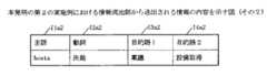
この実施例におけるコンピュータシステム2bの情報反応テーブル203bの内容を図12に示す。ここでは、動詞T2b1には、「問い合わせ」や「決裁」、「打合せ」の依頼など、日常業務で発生する事項が登録されている。「問い合わせ」については、主語T1b1,目的語1T3b1および目的語2T4b1も "*" であるため、誰からどのような問い合わせがあったとしても反応することを意味する。「決裁」については、稟議の決裁については誰からの依頼であっても反応することを意味する。「打合せ」については、ホスト名が"hosta" あるいはホスト名が"hostc" であるコンピュータシステム1a,3c の依頼のみに反応することを意味する。
【0040】
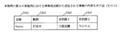
コンピュータシステム3cの情報反応テーブル303cの内容を図13に示す。ここでは、動詞T2c1には、「問い合わせ」や「打合せ」の依頼などが登録されている。「問い合わせ」については、クラサバシステムに関する問い合わせのみ、誰からの問い合わせであっても反応することを意味する。「打合せ」については、ホスト名が"hosta" あるいはホスト名が"hostb" であるコンピュータシステム1a,2b の依頼のみに反応することを意味する。
【0041】
ここで、コンピュータシステム1aが、クラサバシステムを構築する上での留意点を問い合わせたとする。この場合に、情報流通部101aが生成する情報の内容を図14に示す。
主語I1a1には、コンピュータシステム1aのホスト名"hosta" が設定され、動詞I2a1には、問い合わせであることを示す "問い合わせ" が設定され、目的語1I3a1には、問い合わせ内容の大項目として "クラサバシステム" が設定され、目的語2I4a1には、問い合わせ内容の小項目として "構築上の留意点" が設定される。この情報は生成されると、共通の通信路であるLAN3Lに送出される。
【0042】
コンピュータシステム2bの情報検知部202bは、LAN3Lを流れてきた前記情報を受信すると、前記情報反応テーブル203bを検索する。情報反応テーブル203bには、動詞T2b1に前記情報の動詞I2a1に設定された "問い合わせ" が登録されており、主語T1b1、目的語1T3b1および目的語2T4b1が "*" であるため、情報検知部202bは流れてきた情報と情報反応テーブル203bの内容が合致したと判断し、登録されている処理内容T5b1を実行する。ここでは、質問応答システムを起動し、問い合わせ内容を表示する。
【0043】
コンピュータシステム3cでも同様に、情報反応テーブ303cに「問い合わせ」が登録されており、反応すべき問い合わせ内容を目的語1T3c1に「クラサバシステム」と限定しているが、コンピュータシステム1aからの問い合わせが、クラサバシステムに関するものであるため、前記同様に反応する。
次に、コンピュータシステム1aから、稟議の決裁を依頼することを想定する。
【0044】
コンピュータシステム1aの情報流出部101aは、図15に示す情報を生成する。
主語I1a2には、コンピュータシステム1aのホスト名"hosta" が設定され、動詞I2a2には、決裁の依頼であることを示す "決裁" が設定され、目的語1I3a2には、決裁依頼内容の大項目として "稟議" が設定され、目的語2I4a2には、決裁依頼内容の小項目として "設備取得" が設定される。この情報は生成されると、共通の通信路であるLAN3Lに送出される。
【0045】
コンピュータシステム2bの情報検知部202bは、LAN3Lを流れてきた前記情報を受信すると、前記情報反応テーブル203bを検索する。情報反応テーブル203bには、動詞T2b1に前記情報の動詞I2a2に設定された "決裁" が登録されており、目的語1T3b1が "稟議" であり、主語T1b1および目的語2T4b1が "*" であるため、情報検知部202bは流れてきた情報と情報反応テーブル203bの内容が合致したと判断し、登録されている処理内容T5b1を実行する。ここでは、稟議システムを起動し、決裁依頼内容を確認する。
【0046】
コンピュータシステム3cは、情報反応テーブル303cに「決裁」に関して登録されていないため、なんら反応を示さない。
さらに、ここで例えばコンピュータシステム1aを秘書が使用していると想定し、コンピュータシステム1aの情報反応テーブル103aの主語は誰でもよく、動詞に "決裁" 、目的語1および目的語2も何でもよいとし、処理内容として「決裁依頼の内容と受信者を表示する」と登録しておけば、前記決裁の依頼が発生するたびに、秘書の使用しているコンピュータシステム1aにその内容と誰が受信したかが逐次表示され、稟議書が回議ルートのどこにいるのかを逐次把握することも可能となる。
【0047】
次に、コンピュータシステム1aから、打合せの招集を行うことを想定する。
コンピュータシステム1aの情報流出部101aは、図16に示す情報を生成する。
主語I1a2には、コンピュータシステム1aのホスト名"hosta" が設定され、動詞I2a3には、打合せの依頼であることを示す "打合せ" が設定され、目的語1I3a3には、打合せの大項目として "工程会議" が設定され、目的語2I4a3には、打合せの小項目として "プロジェクトA" が設定される。この情報は生成されると、共通の通信路であるLAN3Lに送出される。
【0048】
コンピュータシステム2bの情報検知部202bは、LAN3Lを流れてきた前記情報を受信すると、前記情報反応テーブル203bを検索する。情報反応テーブル203bには、動詞T2b1に前記情報の動詞I2a3に設定された "打合せ" が登録されており、コンピュータシステム1a,3c からの打合せ依頼であれば、どのような打合せでも反応することが登録されているため、情報検知部202bは流れてきた情報と情報反応テーブル203bの内容が合致したと判断し、登録されている処理内容T5b1を実行する。ここでは、スケジュール管理システムを起動し、空き状況を通知する。
【0049】
コンピュータシステム3cでも、情報反応テーブル303cの内容から同様の反応が行われる。
このように、複数の人間で共通業務を請け負って推進していく際の連携システム(例えば、グループウェアなど)の構築も可能であるし、決裁などもその職位に応じた権限内容を情報反応テーブルに設定しておくことにより、企業内の連携システムの構築も可能である。
<第1および第2実施例の具体的な実施例>
今まで述べてきた実施例を具体的に実現する際の一例を下記に示す。
【0050】
まず、請求項に示す共通の通信路およびそこに流す情報の形式を定義する例を示す。
virtual void Init(CWnd *pwnd,int PORT=FIELDPORT);
virtual void wisper(const char *subject, const char *verb, const
char *object,const char *object2, BOOL Inform=TRUE,BOOL
Force=FALSE);
本例では、前記関数により、各オブジェクトにClass 定義されることにより、共通の通信路が構成される。ここで、関数Initは共通の通信路を開設するものであり、関数wisperは共通の通信路へ情報を流すためのものである。関数wisperは、さらに下記の関数により、その構造が定義されている。
【0051】
【0052】
関数wisperは呼び出されると、前記構造体wispに情報を設定し、関数Initにより開設されている共通の通信路へ情報を送出する。
次に、情報反応テーブルに関しての具体的な定義の一例を示す。
まず、情報反応テーブルの構造の定義の例を示す。
【0053】
情報反応テーブルへの内容の登録等は、下記の関数で行う。
void CreateSAtab();
void SetTab(const char *verb, const char *object, REACTFUNC func);
void SetTab(const char *subject,const char *verb, const char *object
,const char *object2, REACTFUNC func);
void SetTab(const char *subject,const char *verb, const char *object
,const char *object2, REACTFUNC func, const char *param);
BOOL DelTab(const char *subject,const char *verb, const char *object
,const char *object2, REACTFUNC func);
ここで、関数CreateSAtab は構造体saTab を並べた情報反応テーブルを生成するためのものであり、関数SetTab, 関数DelTabは情報反応テーブルへの追加・削除を行うためのものである。
【0054】
次に、情報検知部の実際の定義の一例を示す。
【0055】
void React(FIELDWISP *wisp);
関数React は、共通の通信路に流れる情報から、自らの持つ情報反応テーブルの内容に応じて反応するためのものである。共通の通信路に流れてくる、前述した構造体wispを監視し、構造体wispを検知すると情報反応テーブルの内容と照合し、合致するものがあった場合には、情報反応テーブルに登録されている処理内容を実施する。
【0056】
なお、上述した関数類は、実現手段のとしての一例であって、その実現手段を限定するものではない。
<第3実施例>
次に、オブジェクトの自由な連携を確保しながら、複雑な処理を実現する実施例を説明する。
【0057】
本実施例を実現する基本的構成は、図6に示す内容と同様であるが、情報反応テーブル103a,203b,303cの内容が図18に示す構成となる。すなわち、反応すべき情報と実行される処理内容が設定された基本テーブルJT1 と、基本テーブルに登録されている情報のうち、複数の情報を検知した後、処理の実行がなされる場合にその対象となる情報のみを登録したチェックリストテーブルJT2 (第1の拡張テーブル)と、検知した情報の活性状態を判定するフラグチェックテーブルJT3 (第2の拡張テーブル)とから構成されている。
【0058】
基本テーブルJT1 の内容の例を説明する。本実施例でも、共通の通信路を流れてくる情報のフォーマットは、第1実施例および第2実施例と同様の形式を想定する。つまり、主語JT1-1 から処理内容JT1-5 までの内容は、前述の実施例と同様である。パラメタJT1-6 の領域は、本実施例ではチェックリストテーブルJT2 のポインタを設定する、あるいは、処理内容JT1-5 に設定された内容を実行する際に必要となるパラメタを設定する領域である。
【0059】
次に、チェックリストテーブルJT2 の内容の例を説明する。主語JT2-1a,bから目的語2JT2-4a,bまでの領域は、基本テーブルJT1 と同様の内容であり、検知された情報が検索される際のキーとなる。検知フラグ領域JT2-5a,bの領域は、当該情報が検知されたかどうかを表す領域であり、ここでは初期値は "0" であり、当該情報が検知された場合は "1”を設定する。これにより、AND制御が可能となる。反転フラグ領域JT2-6a,bは、条件設定時にNOTの指定がなされた場合に "1" が設定され、NOTの指定がなされていない場合は "0" が設定される。情報状態フラグ領域JT2-7a,bは、情報を検知した際に、検知フラグ領域JT2-5a,bと反転フラグ領域JT2-6a,bの内容から、情報の活性状態を設定する領域であり、活性状態と判断された場合は"Active"が、非活性状態と判断された場合は"Inactive"が設定される。
【0060】
次に、フラグチェックテーブルJT3 の内容の例を説明する。フラグチェックテーブルJT3 は、前述の検知フラグ領域JT2-5a,bと反転フラグ領域JT2-6a,bの値により当該情報の活性状態を判定するためのテーブルであり、その値の組み合わせにより、その情報を活性状態(Active)とするか、非活性状態(Inactive)とするかを判断し、情報状態フラグ領域JT2-7 に設定する。
【0061】
図19に基づいて、第3実施例における情報検知部の処理内容を説明する。第3実施例では、情報を検知すると(図19のステップS73)、まず基本テーブルJT1 を検索する(図19のステップS74)。基本テーブルJT1 中に当該情報が存在した場合(図19のステップS75でYesの場合)、パラメタ領域JT1-6 にチェックリストテーブルJT2 へのポインタが設定されているかどうかを判定し(図19のステップS76)、ポインタが設定されていれば(図19のステップS76でYesの場合)、ポインタが示すチェックリストテーブルJT2 を読み込み(図19のステップS77)、当該情報の検知フラグ領域JT2-5 をON("1") 状態に設定する(図19のステップS78)。さらに、更新後の検知フラグ領域JT2-5a,bの値と、当該情報の反転フラグ領域JT2-6a,bの値に基づいて、フラグチェックテーブルJT3 を検索して活性状態を判定し、情報状態フラグ領域JT2-7a,bに設定する(図19のステップS79)。その後、当該チェックリストテーブルJT2 内の情報状態フラグ領域JT2-7a,bを検索し(図19のステップS80)、すべての情報状態フラグJT2-7a,bの値が"Active"になっているかどうかを判断する(図19のステップS81)。すべての情報状態フラグJT2-7a,bの値が"Active"になっている場合は(図19のステップS81でYesの場合)、基本テーブルJT1 に設定されている処理内容JT1-5 を実行する(図19のステップS82)。1つでも情報状態フラグJT2-7a,bの値が"inactive"になっている場合は(図19のステップS81でNoの場合)、処理を実行する条件が整っていないため、次の情報の検知を待つ(図19のステップS72,S73)。
【0062】
第1実施例および第2実施例では、基本テーブルJT1 のみであるため、検知した情報が基本テーブルJT1 に登録されているかどうかを判断するだけで、処理が実行されていた。これは、情報のOR条件のみによる処理の実行制御が行われていたと言える。第3実施例では、パラメタ領域JT1-6 に、処理内容JT1-5 を実行する際に必要となるパラメタか、あるいは、チェックリストテーブルJT2 のポインタかのどちらかを設定可能とすることにより、パラメタが設定されている場合は第1実施例および第2実施例同様に情報の検知と共に処理内容JT1-5 が実行され、ポインタが設定されている場合はチェックリストテーブルJT2 に登録されている情報の検知状況によって処理内容JT1-5 が実行されることになる。
【0063】
この第3実施例では、情報を検知する毎に、チェックリストテーブルJT2 内の検知フラグ領域JT2-5 を判定することにより、複数の情報の検知が確認されるまで処理の実行が抑制され、複数の情報のAND条件による処理の実行制御が実現できる。さらに反転フラグ領域JT2-6 およびフラグチェックテーブルJT3 により、情報のNOT条件による処理の実行制御も可能となっている。 また、これらの組み合わせ条件による処理の実行制御も可能となる。
【0064】
さらに、図20に示すように、チェックリストテーブルJT2 の反応制御領域JT2-8cを設けることにより、情報を検知した回数に応じて、処理を行うように制御することも可能である。この場合、情報を検知する毎に検知フラグ領域JT2-5cの値を加算していき、反応制御領域JT2-8cと同じ値になったら、所定の処理を実行するといった、カウントアップ方式で制御するもの1つの方法である。また、情報を検知する毎に反応制御領域JT2-8cの値を減算していき、値が "0" になったら処理内容を実行するといいた、カウントダウン方式で制御するのも1つの方法である。
【0065】
これにより、前述のAND,OR,NOT制御に加え、IF制御が可能となる。また、これらを組み合わせ条件とすることも可能である。
なお、本実施例では、請求項3及び請求4の構成要件に基づいた実施例を示したが、前述の基本テーブルは設けずに、拡張テーブルのみで実現することも可能である。この場合、検知すべき情報群毎に個別に反応テーブルが生成され、情報検知部は、次オブジェクトに関連付けられた反応テーブル群をすべて参照し、フラグ領域の更新や、定義された処理内容の実行を行うことになる。これにより、さらに簡易に、柔軟な連携を確保しつつ、複雑な処理を行うことが実現が可能となる。
<第4実施例>
第4実施例では、情報反応テーブル103a,203b,303cを構築する機能を説明する。本機能は、前述の機能を実行するプログラムの一機能として提供される。
【0066】
本機能は、たとえば、図21に示すような設定画面を表示し、情報反応テーブル103a,203b,303cの設定を容易にする。
設定画面SCは、情報反応テーブル103a,203b,303cに登録する情報を操作するボタンB1,B2 、登録する情報の内容を入力する入力領域I1、登録する情報の関係式を設定するチェックボックスC1,C2,C3、当該登録情報を検知した際に実行すべき処理内容を設定する処理内容入力領域I2、さらにその設定メッセージをメッセージボックスとして表示するかどうかを指示するチェックボックスC4から構成されている。
【0067】
図21の例では、登録する情報の内容を入力する入力領域I1は、1つの枠となっているが、連携システム内で情報の形式をどのように規定するかによって、その形式に則った表示が行われる。前述の実施例では、情報の形式は、主語、述語、目的語1、目的語2から構成されるため、たとえば、それぞれ所定の枠として、4つの入力領域に分割されていてもよいし、所定の区切文字により、1文で入力された内容を自動的に区切って、情報反応テーブルに登録するようにしてもよい。
【0068】
まず、各種ボタンB1,B2,B3の説明をする。
AdAddボタンB1は、情報反応テーブル103a,203b,303cに情報を登録する際に使用する。DeleteボタンB2は、情報反応テーブル103a,203b,303cに登録されている情報を削除する際に使用する。ResetボタンB3は、情報反応テーブル103a,203b,303c中の検知フラグ領域JT2-5a,bなど、情報の検知に伴い、その状態が変化していく領域に対して、初期状態に設定し直す際に使用する。
【0069】
新たに、情報反応テーブルに情報を登録することを想定する。
入力領域I1に登録する情報を入力する。ここでは、Button-Aという情報がNOT条件で登録され、さらにButton-Bを追加しようとしている。Button-A(not) の情報と新たに登録するButton-Bの情報の関係をANDのチェックボックスをクリックすることにより指示している。次に、情報を検知した際に実行すべき処理内容を処理内容入力領域I2に設定する。この際、処理内容によっては、メッセージを表示する際にメッセージボックスを表示させることを、Message Box のチェックボックスC3を指示することにより行える。ここで、AddボタンB1を指示すると、画面上の指示内容から、Not Button-A ∩ Button-Bが指示されていることを認識する。ORの指定がなされている場合は、情報に対して、個別に反応すればよいため、基本テーブルJT1 に入力された内容を登録する。AND条件の場合は、基本テーブルJT1 のみならず、拡張テーブルへの登録も必要となる。入力された情報の組を1つのテーブルとして生成する。さらに、NOT条件が設定されている場合は、反転フラグ領域JT2-6a,bno初期状態を "1" に設定するなどの処理を行う。
【0070】
このように、視覚的に情報反応テーブルを設定できるため、複雑な処理を登録する際も容易にその情報が登録できる。
<その他の実施例>
情報流出部および情報検知部は、オブジェクト毎に設けるようにしているが、パソコンシステムに1つ設け、複数のオブジェクトから共有されるようにしてもよい。また、情報反応テーブルを情報検知部内に設けるなど、各モジュールの構成は、本実施例に限られるものではない。
【0071】
情報反応テーブルの内容についても、例えば図8の動詞を例にあげると、"AddClip*"と定義することにより、"AddClipText" 、"AddClipFile" 、"AddClipMetaFile" のすべてと一致する前方一致あるいは、逆の後方一致による登録を行ってもよい。これは、主語、目的語1および目的語2についても同様である。
また、情報流出部より送出される情報に図17に示すようなフラグを追加することにより、オブジェクトが反応するかどうかを予め確認してから、再度正式な情報を送出し直す、あるいは、受信したオブジェクトから反応した結果を必ず返送してもらうなどの制御が可能となる。具体的には、フラグInformT6の値により、送出した情報に対して受信したオブジェクトが情報反応テーブルに登録された処理内容を実行するのみ(値が"0" の時)か、処理内容を実行せずに、情報反応テーブルに反応すべき内容として登録されていることのみを返答する(値が"1" の時)のみかを制御する。
【0072】
また、フラグForceT7 の値により、受信したオブジェクト側で処理された内容を通知するかどうかを制御することが可能となる。具体的には、フラグForceT7 の値が'0" の時、送出された情報を受信して反応した場合、処理内容を実行するのみで、その実行結果を特に通知せず、フラグForceT7 の値が'0" の時、実行結果を返答する。
【0073】
共通の通信路においても、LANだけでなく、IrDAなど赤外線通信や、携帯電話やPHSなどの無線電話通信や、テレビ放送電波など、他の通信手段でも良い。
また、LANで使用されるプロトコルも、UDPやIRCなどがあるが、これに限定される訳ではない。ちなみに、UDP(User Datagram Protocol)は、OSI(Open Systems Interconnection)の第4層に位置するプロトコルであり、コネクションレスの通信を提供する。 UDPでは、通信のエンドポイントの識別に、IPアドレスとポート番号の組み合わせを利用し、これによって一つのアドレスに対して複数の宛先を指定することができる。UDPでは、パケットの再送や順序制御、フロー制御などの制御を行わない。本発明の共通の通信路としてUDPを利用する場合、共通の通信路にポート番号を結びつけ、共通のポート番号を使うことによって共通にアクセス可能な通信路とする。
【0074】
IRCは1988年にFinland Oulu大学のOikarinennによって開発されたInternet上のテキストベースの電子会議を行うためのシステムで、サーバ−クライアント間のプロトコルはRFC1459 という形式で公開されている。IRCではユーザーはチャネルと呼ばれる場所で会話を行い、このチャネルはIRCの持つサーバ−サーバー間の連携プロトコルによってInternet上に広がっている。本発明における共通の通信路としてIRC を利用する場合、共通の通信路にチャネルを結びつけ、共通のチャネルを使うことによって共通にアクセス可能な通信路とする。
【0075】
また、本発明の特徴として掲げている記憶媒体は、磁気テープやフロッピーディスクあるいはCD−ROM(光磁気ディスク記録媒体)などの可搬媒体のみならず、通信回線などを介してサーバ機やホストセンタなどから伝送データとして提供される方式も含む。
【0076】
【発明の効果】
以上、説明した通り、本発明により、情報の送信側は相手や実行すべき内容を意識することなく単に情報を流すだけでよく、情報の受信側も必要な情報のみに反応し、また受信した情報の解釈も受信側で任意となるため、相互の関係性を意識しない柔軟な連携システムの構築が可能となる。また、情報反応テーブルにフラグ領域を設け、そのフラグ領域の内容を判断する手段を設けることにより、AND,OR,NOT,IF制御が可能となり、いわばソフトウェア論理回路の実現も可能となり、より柔軟な連携処理システムを維持しつつ、複雑な処理ロジックを展開することも可能となる。
【図面の簡単な説明】
【図1】本発明の基本構成を示す図
【図2】情報流出部から送出される情報の内容の例を示す図
【図3】情報反応テーブルの内容の例を示す図
【図4】情報流出部の処理の内容を示すフローチャート
【図5】情報検知部の処理の内容を示すフローチャート
【図6】本発明の第1実施例の構成を示す図
【図7】本発明の第1実施例における情報反応テーブルの内容を示す図(その1)
【図8】本発明の第1実施例における情報反応テーブルの内容を示す図(その2)
【図9】本発明の第1実施例における情報反応テーブルの内容を示す図(その3)
【図10】本発明の第1実施例における情報流出部より送出される情報の内容を示す図(その1)
【図11】本発明の第1実施例における情報流出部より送出される情報の内容を示す図(その2)
【図12】本発明の第2実施例における情報反応テーブルの内容を示す図(その1)
【図13】本発明の第2実施例における情報反応テーブルの内容を示す図(その2)
【図14】本発明の第2実施例における情報流出部より送出される情報の内容を示す図(その1)
【図15】本発明の第2実施例における情報流出部より送出される情報の内容を示す図(その2)
【図16】本発明の第2実施例における情報流出部より送出される情報の内容を示す図(その3)
【図17】本発明のその他の実施例における情報流出部より送出される情報に追加されるフラグの内容を示す図
【図18】本発明の第3の実施例における情報反応テーブルの内容を示す図
【図19】本発明の第3の実施例における情報検知部の処理の内容を示すフローチャート
【図20】その他の実施例におけるチェックリストテーブルの内容を示す図
【図21】本発明の情報反応テーブルの登録画面の一例を示す図
【図22】従来の方式を説明する図[0001]
BACKGROUND OF THE INVENTION
The present invention relates to a cooperation method when performing cooperation processing such as communication, dialogue, and cooperation between distributed objects, and particularly to various information flowing through a communication path as defined as a common field as an object. The present invention relates to a new linkage system in which processing is executed in such a manner that individual computer systems or individual application programs operating in the computer system react independently.
[0002]
[Prior art]
In recent years, with the progress of networking, a system in which a plurality of objects distributed on a network perform processing in cooperation with each other is increasing. Researches such as object-oriented programming and component technology have been made as techniques for processing such a plurality of objects in cooperation.
[0003]
As an example of object-oriented programming, the common object CORBA (The Common Object Request Broker: Architecture) for distributed object operation defined by the industry organization OMG (Object Management Group) established with the aim of standardizing and spreading object-oriented technology and Specification).
FIG. 22 shows an example of object cooperation in a client / server system based on CORBA. Here, each of the applications 1211, 1221 corresponds to an object. In this system, a client application 1211 and a server application 1221 cooperate to perform a series of processing by object cooperation.
[0004]
The application developer describes an interface of a service provided by each application 1211, 1221 in an IDL (Interface Definition Language) 1202. The content defined as an interface is an operation group that can be requested to an object. Each operation defines an operation name, parameter definition, return value definition, exception handling when an error occurs, additional information, and the like.
[0005]
By compiling the contents defined by the
[0006]
The
[0007]
[Problems to be solved by the invention]
As described above, it has become easy to construct an object cooperation process using CORBA or the like. However, in order to actually construct such a cooperative process, if it is the above-mentioned CORBA, it is necessary to understand the CORBA itself and to design an object according to the CORBA specification and to define it by IDL. In other words, it is necessary for the person who builds the system to know how to use it.
[0008]
In addition, it is necessary to be strongly aware of the relationship between each object. In other words, it is necessary to clarify what kind of processing each object performs and what the delivery parameters are necessary to perform the processing.
Although the independence of the objects has been increased by making the interface between the objects common, it is assumed that there is a fixed relationship between the objects.
[0009]
Here, when considering communication between humans, indefinite exchanges often occur in reality. For example, assuming that a problem is to be solved, in order to solve the problem that has occurred, he / she thinks about himself / herself or seeks advice from another person and leads the solution. Even when I am thinking about myself, there are various points of view. In addition, when seeking advice from another person, there are cases where a specific person is inquired and a broadly unspecified person is inquired. When inquiring a wide range of unspecified people, each person's response is different.
Those who have a solution will give answers, some may give advice by analogy with their own experience and knowledge, rather than a direct solution, and are completely indifferent. Some people will ignore the inquiry. That is, for one information, whether or not it responds to the information differs depending on the receiving side, and how it reacts also varies depending on the receiving side.
[0010]
Here, when a person is replaced with an object, each object receives / does not receive the information that flows, and what kind of processing is performed on the received information Are different, in other words, it is desired that the relationship between objects is free. The conventional linkage method is based on the premise that the relationship between objects is fixed, and it has been difficult to construct a linkage system having such a free relationship.
[0011]
An object of the present invention is to increase the degree of freedom of cooperation between objects connected to a network.
[0012]
[Means for Solving the Problems]
The present inventionIn a network system in which a plurality of computers are connected, each computer includes processing content information processed by its own computer for the network to which the plurality of computers are connected, and is preliminarily determined in common in the network system. A portion for sending a message in a format, a portion for monitoring the processing content information contained in the message in a predetermined format sent from another computer to a network to which a plurality of computers are connected, Among the messages in a predetermined format, a reaction table that associates processing content information to be reacted with processing to be executed when the processing content information is detected is provided. In the monitoring part, processing content information to be reacted was detected , To provide a network system adapted to execute processing corresponding with reference to the reaction table which receives the message.
[0013]
The present invention is an object cooperation method used in a system in which an object that operates on a computer is connected to be communicable with another object via a common communication path, and performs processing in cooperation between a plurality of objects, Each object generates processing content information processed by its own object in a format pre-determined in common in the system, and a transmission means for sending the processing content information to a common communication path, Corresponding processing content information to be reacted to the processing content information in a predetermined format flowing in the communication path and processing content to be executed corresponding to the processing content information to be reacted A stored information reaction table and monitoring means for monitoring processing content information in a predetermined format flowing in a common communication path are realized, The monitoring means collates the processing content information in a predetermined format flowing in the common communication path with the processing content information to be reacted in the information reaction table, and flows to the common communication path. It is determined whether or not to react to the processing content information of a predetermined format that comes in advance, and the processing content defined in the information reaction table is executed only for the processing content information to be reacted.
[0014]
In the present invention, the information reaction table includes a basic table and one or a plurality of first extension tables, and the first extension table includes information among objects registered in the basic table. Information transmitted in a predetermined format is registered, and further includes an information detection flag area for confirming whether or not the information has been detected, and the monitoring means is a process that has flowed through the common communication path. When content information is detected, the information detection flag area of the processing content information in the first extension table is changed to a detected state, and then registered in the first extension table in relation to the processing content information The information detection flag area of all the processed content information is determined, and only when all the information detection flag areas are already detected, the basic information is associated with the processed content information. Executing the defined processing content to Buru.
[0015]
According to the present invention, the information reaction table further includes a second extension table, the first extension table further includes an inversion flag area and an information status flag area, and the second extension table includes an information detection flag. And state control information for controlling whether to activate the processing content information according to the reverse flag area, and the monitoring means detects the processing content information flowing through the common communication path In addition, the information detection flag area of the processing content information in the first extension table is changed to a detected state, and the information of the processing content information in the first extension table is referred to by referring to the second extension table. The value of the state control information corresponding to the values of the detection flag area and the inversion flag area is set in the information state flag area, and the information states of all information registered in the first extension table in relation to the processing content information F Determines grayed area, all the information status flag area only if it is in an active state, executes the processing contents defined in the base table in association with the processing content information.
[0016]
The present invention is a storage medium that stores a program for causing a computer used in a system that performs processing in cooperation between independent objects to execute the following means, and is predetermined in advance in the system. Sending means for sending processing content information generated in a format and processed by its own object to a common communication path, and processing content information generated in the predetermined format sent on a common communication path A detection means for detecting, an information reaction table in which processing content information to be reacted to the processing content information and processing content to be executed corresponding to the processing content information to be reacted are stored in association with each other. The processing content information generated in the previously determined format that has been detected in common is checked to determine whether or not to react to the processing content information, and the processing to react Selection means for selecting a processing content to be processed in response to processing content information defined in the information reaction table only for content information, and command means for instructing execution of the selected processing content. Are recorded in a computer-readable storage medium storing a program for realizing the above.
[0017]
The present invention further includes a program for causing the computer to realize an interface function for registering the processing content information to be detected.
[0019]
DETAILED DESCRIPTION OF THE INVENTION
An embodiment of a network system using the object cooperation method of the present invention will be described below.
FIG. 1 shows a basic configuration diagram of the present invention.
The plurality of
[0020]
The
The
[0021]
The information reaction tables 103 and 203 define what processing is executed when the
Here, the
[0022]
FIG. 2 shows an example of the format of information generated by the
In the subject I1, an identifier for identifying the
Here, the host name assigned to the computer system where
[0023]
For the verb I2, the information type transmitted from the
In the object 1I3 and the object 2I4, a delivery parameter required according to the verb I2 is set.
[0024]
The format of this information only needs to be unified within the cooperation system, and is not limited to this format.
FIG. 3 shows an example of the contents of the information reaction tables 103 and 203. The table has a subject T1, verb T2, object 1T3, object 2T4 corresponding to the contents of information sent from the
[0025]
FIG. 4 is a flowchart showing the contents of processing of the
[0026]
Thereafter, the
[0027]
Information transmitted from the
FIG. 5 is a flowchart showing the contents of processing of the
[0028]
Next, details of the embodiments of the present invention will be described.
<First embodiment>
FIG. 6 is a diagram showing the configuration of this embodiment.
The computer systems 1a, 2b, 3c are connected to each other via a LAN 3L.
The information shown in FIG. 7 is registered in the information reaction table 103a of the computer system 1a. In verb T2a, the operation type related to the mouse operation is registered, and since the subject T1a is all "*", it was performed in all computer systems 1a, 2b, 3c connected to a common communication path. It means to respond to mouse operation.
[0029]
The information shown in FIG. 8 is registered in the information reaction table 203b of the computer system 2b. The verb T2b contains the operation types related to file copy, and the contents of the subject T1b are all “*”, so the files executed on all computer systems 1a, 2b, and 3c connected to the common communication path It means to react to the copy operation.
[0030]
An information reaction table 303c of the computer system 3c is registered. As shown in FIG. 9, the information reaction table 303c responds to a mouse operation. Unlike the information reaction table 103a of the computer system 1a, the cursor movement by the mouse 104b of the computer system 2a (host name: hostb) is performed. It is set to react only to operations.
[0031]
First, it is assumed that a file copy operation is performed in the computer system 1a. In this file copy operation, it is assumed that text data provided as a basic function in the basic software of a personal computer is copied by cut and paste. For example, a copy operation is instructed by designating a text data copy location with a mouse or the like in software for editing text data. When this operation is performed, the
[0032]
The subject I1a is set to the host name “hosta” of the computer system 1a, the verb I2a is set to “AddClipText” indicating that the text data has been copied, and the object 1I3a and the object 2I3b are set to A directory name and a file name indicating a place where the text data to be copied is temporarily stored are set.
When this information is generated, it is sent to the LAN 3L, which is a common communication path.
[0033]
When the information detection unit 202a of the computer system 2a receives the information flowing to the LAN 3L, the information detection unit 202a searches the information reaction table 203b. In the information reaction table 203b, “AddClipText” set in the verb I2a of the information is registered in the verb T2b, and the subject T1b is “*”. It is determined that the contents of the table match, and the registered processing content T5b is executed. Here, the contents of the text data saved by the copy operation are restored.
[0034]
However, in the computer system 3c, since no response to the file copy operation is registered in the information reaction table 303c, there is no response to the information flowing from the computer system 1a.
Next, a case where a cursor moving operation with the mouse 204b is performed in the computer system 2b will be described. The information outflow unit 201b of the computer system 2b generates information indicating that a cursor moving operation with the mouse 204b has been performed in the computer system 2b. The contents of the generated information are shown in FIG.
[0035]
The host name “hostb” of the computer system 2b is set for the subject I1b, and “MouseMove” indicating that the cursor movement operation with the mouse 204b is performed for the verb I2b, the object 1I3b and the object 2I4b The position information of the cursor moved by the mouse 204b is set by acquiring the coordinate data of the display unit 205b.
The information outflow unit 201b sends the generated information to the LAN 3L that is a common communication path.
[0036]
When the
[0037]
Also in the computer system 3c, information related to mouse operations is registered in the information reaction table 303c. Here, the host name “hostb” indicating the computer system 2b is registered in the subject T1c, and “MouseMove” indicating the cursor movement operation with the mouse is registered in the verb T2c. As a result, the
[0038]
As described above, according to the contents of the information reaction tables 103a, 203b, and 303c registered in the computer systems 1a, 2b, and 3c, each computer system can receive the same information and operate in the same manner. In addition, it is possible to cause each computer system to perform a different operation. Furthermore, by not registering in the information reaction table, it is possible for each computer system to not react to the flowing information.
<Second embodiment>
Next, another embodiment of the present invention will be shown.
[0039]
The configuration of this embodiment is the same as that of the first embodiment shown in FIG.
FIG. 12 shows the contents of the information reaction table 203b of the computer system 2b in this embodiment. Here, in the verb T2b1, items that occur in daily work such as requests for “inquiry”, “decision”, and “meeting” are registered. As for “inquiry”, since the subject T1b1, the object 1T3b1 and the object 2T4b1 are also “*”, it means that no matter what kind of inquiry is received from anyone. For “approval”, it means that any request from anyone will respond to the approval of the decision. “Meeting” means responding only to requests from the computer systems 1a and 3c whose host name is “hosta” or whose host name is “hostc”.
[0040]
The contents of the information reaction table 303c of the computer system 3c are shown in FIG. Here, a request for “inquiry” or “meeting” is registered in the verb T2c1. “Inquiry” means that only inquiries about the Crassaba system respond to any inquiries from anyone. “Meeting” means responding only to requests from the computer systems 1a and 2b whose host name is “hosta” or whose host name is “hostb”.
[0041]
Here, it is assumed that the computer system 1a inquires about points to be considered when constructing the Kurasaba system. In this case, the contents of the information generated by the
The subject I1a1 is set to the host name “hosta” of the computer system 1a, the verb I2a1 is set to “inquiry” indicating that it is a query, and the object 1I3a1 is set to “crasava” as the main item of the query content. "System" is set, and "Considerations for construction" is set in the object 2I4a1 as a sub-item of the inquiry content. When this information is generated, it is sent to the LAN 3L, which is a common communication path.
[0042]
When the
[0043]
Similarly, in the computer system 3c, “inquiry” is registered in the information reaction table 303c, and the inquiry content to be responded is limited to “curacaba system” in the object 1T3c1, but the inquiry from the computer system 1a is Since it is related to the Kurasaba system, it reacts in the same manner as described above.
Next, it is assumed that the computer system 1a requests the approval of the approval.
[0044]
The
The host name “hosta” of the computer system 1a is set in the subject I1a2, “decision” is set in the verb I2a2 to indicate that it is a request for approval, and the object 1I3a2 has major items of the contents of the approval request. “Approval” is set, and “Acquisition of equipment” is set in the object 2I4a2 as a sub-item of the content of the approval request. When this information is generated, it is sent to the LAN 3L, which is a common communication path.
[0045]
When the
[0046]
Since the computer system 3c is not registered in the information reaction table 303c regarding “decision”, no response is shown.
Further, here, for example, assuming that the secretary is using the computer system 1a, the subject of the information reaction table 103a of the computer system 1a can be anyone, the verb can be "decision", and the
[0047]
Next, it is assumed that a meeting is convened from the computer system 1a.
The
The host name “hosta” of the computer system 1a is set for the subject I1a2, “meeting” is set for the verb I2a3, which indicates a request for a meeting, and the object 1I3a3 contains “ “Process Meeting” is set, and “Project A” is set as a small item for the meeting in the object 2I4a3. When this information is generated, it is sent to the LAN 3L, which is a common communication path.
[0048]
When the
[0049]
In the computer system 3c, a similar reaction is performed from the contents of the information reaction table 303c.
In this way, it is possible to build a collaborative system (for example, groupware, etc.) when contracting and promoting common work by multiple people, and the information response table also determines the authority contents according to the position of the approval, etc. By setting it to, it is possible to build a collaborative system within the company.
<Specific Examples of the First and Second Examples>
An example when the embodiment described so far is specifically realized will be described below.
[0050]
First, an example of defining the common communication path and the format of information flowing therethrough will be shown.
virtual void Init (CWnd * pwnd, int PORT = FIELDPORT);
virtual void wisper (const char * subject, const char * verb, const
char * object, const char * object2, BOOL Inform = TRUE, BOOL
Force = FALSE);
In this example, a common communication path is configured by defining a class for each object by the function. Here, the function Init opens a common communication path, and the function wisper is for flowing information to the common communication path. The structure of the function wisper is further defined by the following functions.
[0051]
[0052]
When the function wisper is called, information is set in the structure wisp, and the information is transmitted to the common communication path established by the function Init.
Next, an example of a specific definition regarding the information reaction table is shown.
First, an example of the definition of the structure of the information reaction table is shown.
[0053]
The following functions are used to register contents in the information reaction table.
void CreateSAtab ();
void SetTab (const char * verb, const char * object, REACTFUNC func);
void SetTab (const char * subject, const char * verb, const char * object
, const char * object2, REACTFUNC func);
void SetTab (const char * subject, const char * verb, const char * object
, const char * object2, REACTFUNC func, const char * param);
BOOL DelTab (const char * subject, const char * verb, const char * object
, const char * object2, REACTFUNC func);
Here, the function CreateSAtab is for generating an information reaction table in which the structures saTab are arranged, and the function SetTab and the function DelTab are for adding to and deleting from the information reaction table.
[0054]
Next, an example of the actual definition of the information detection unit is shown.
[0055]
void React (FIELDWISP * wisp);
The function React is for reacting according to the contents of the information reaction table of its own from information flowing in a common communication path. The structure wisp that flows in the common communication path is monitored, and when the structure wisp is detected, it is checked against the contents of the information reaction table. If there is a match, it is registered in the information reaction table. Implement the processing contents.
[0056]
Note that the functions described above are examples of implementation means, and do not limit the implementation means.
<Third embodiment>
Next, an embodiment for realizing complicated processing while ensuring free cooperation of objects will be described.
[0057]
The basic configuration for realizing the present embodiment is the same as the content shown in FIG. 6, but the content of the information reaction tables 103a, 203b, and 303c is the configuration shown in FIG. In other words, the basic table JT1 in which the information to be reacted and the processing contents to be executed are set, and the information to be processed when the processing is executed after detecting multiple pieces of information registered in the basic table The check list table JT2 (first extension table) in which only the information to be registered is registered, and the flag check table JT3 (second extension table) for determining the active state of the detected information.
[0058]
An example of the contents of the basic table JT1 will be described. Also in the present embodiment, the format of information flowing through the common communication path is assumed to be the same format as in the first and second embodiments. That is, the contents from the subject JT1-1 to the processing content JT1-5 are the same as those in the above-described embodiment. In the present embodiment, the parameter JT1-6 area is used to set a pointer required for the checklist table JT2 or to set parameters necessary for executing the contents set in the processing contents JT1-5.
[0059]
Next, an example of the contents of the checklist table JT2 will be described. The area from the subject JT2-1a, b to the object 2JT2-4a, b has the same contents as the basic table JT1, and serves as a key when the detected information is searched. The detection flag area JT2-5a, b is an area indicating whether or not the information is detected. Here, the initial value is “0”, and “1” is set when the information is detected. . Thereby, AND control becomes possible. In the inversion flag area JT2-6a, b, "1" is set when NOT is specified at the time of condition setting, and "0" is set when NOT is not specified. Information state flag area JT2-7a, b is an area for setting the active state of information from the contents of detection flag area JT2-5a, b and reverse flag area JT2-6a, b when information is detected, “Active” is set when the active state is determined, and “Inactive” is set when the active state is determined.
[0060]
Next, an example of the contents of the flag check table JT3 will be described. The flag check table JT3 is a table for determining the active state of the information based on the values of the detection flag areas JT2-5a, b and the inversion flag areas JT2-6a, b described above. Is set to the active state (Active) or inactive state (Inactive), and is set in the information state flag area JT2-7.
[0061]
Based on FIG. 19, the processing content of the information detection part in 3rd Example is demonstrated. In the third embodiment, when information is detected (step S73 in FIG. 19), the basic table JT1 is first searched (step S74 in FIG. 19). If the information is present in the basic table JT1 (Yes in step S75 in FIG. 19), it is determined whether or not a pointer to the checklist table JT2 is set in the parameter area JT1-6 (step in FIG. 19). If the pointer is set (Yes in step S76 in FIG. 19), the check list table JT2 indicated by the pointer is read (step S77 in FIG. 19), and the detection flag area JT2-5 of the information is turned on. ("1") state is set (step S78 in FIG. 19). Further, based on the updated value of the detection flag area JT2-5a, b and the value of the inversion flag area JT2-6a, b of the information, the flag check table JT3 is searched to determine the active state, and the information state The flag area JT2-7a, b is set (step S79 in FIG. 19). Then the checklistToteThe information status flag area JT2-7a, b in the table JT2 is searched (step S80 in FIG. 19), and it is determined whether or not the values of all the information status flags JT2-7a, b are “Active” (FIG. 19). 19 step S81). If the values of all the information status flags JT2-7a, b are “Active” (Yes in step S81 in FIG. 19), the processing content JT1-5 set in the basic table JT1 is executed. (Step S82 in FIG. 19). If even one of the information status flags JT2-7a, b is “inactive” (No in step S81 in FIG. 19), the condition for executing the process is not ready, so the next information Waiting for detection (steps S72 and S73 in FIG. 19).
[0062]
In the first and second embodiments, since only the basic table JT1 is used, the processing is executed only by determining whether or not the detected information is registered in the basic table JT1. It can be said that the execution control of the process is performed only by the OR condition of the information. In the third embodiment, the parameter area JT1-6 can be set with either a parameter required when executing the processing content JT1-5 or a pointer of the checklist table JT2. Is set, the processing contents JT1-5 are executed together with the detection of information as in the first and second embodiments, and when the pointer is set, the information registered in the checklist table JT2 is displayed. Processing content JT1-5 is executed depending on the detection status.
[0063]
In the third embodiment, each time information is detected, the detection flag area JT2-5 in the checklist table JT2 is determined, so that the execution of processing is suppressed until the detection of a plurality of information is confirmed. The execution control of the processing based on the AND condition of the information can be realized. Further, the execution control of the processing based on the NOT condition of the information is possible by the reverse flag area JT2-6 and the flag check table JT3. Further, execution control of processing based on these combination conditions is also possible.
[0064]
Furthermore, as shown in FIG. 20, by providing a reaction control region JT2-8c of the checklist table JT2, it is possible to control to perform processing according to the number of times information is detected. In this case, each time information is detected, the value of the detection flag area JT2-5c is added, and when the value becomes the same as that of the reaction control area JT2-8c, a predetermined process is executed to control by a count-up method. One method. In addition, it is one method to control by the countdown method in which the value of the reaction control area JT2-8c is subtracted every time information is detected, and the processing content is executed when the value becomes “0”. .
[0065]
Thereby, in addition to the above-described AND, OR, NOT control, IF control is possible. These can also be used as a combination condition.
In the present embodiment, the embodiment based on the configuration requirements of
<Fourth embodiment>
In the fourth embodiment, a function for constructing the information reaction tables 103a, 203b, and 303c will be described. This function is provided as one function of a program that executes the above function.
[0066]
This function, for example, displays a setting screen as shown in FIG. 21, and facilitates the setting of the information reaction tables 103a, 203b, and 303c.
The setting screen SC includes buttons B1 and B2 for operating information to be registered in the information reaction tables 103a, 203b, and 303c, an input area I1 for inputting contents of information to be registered, and a check box C1 for setting a relational expression of information to be registered. C2 and C3, a processing content input area I2 for setting processing content to be executed when the registered information is detected, and a check box C4 for instructing whether or not to display the setting message as a message box.
[0067]
In the example of FIG. 21, the input area I1 for inputting the contents of the information to be registered is one frame, but depending on how the information format is defined in the linkage system, the display according to the format is displayed. Is done. In the above-described embodiment, the information format is composed of the subject, predicate,
[0068]
First, various buttons B1, B2, and B3 will be described.
The AdAdd button B1 is used when registering information in the information reaction tables 103a, 203b, and 303c. The Delete button B2 is used when deleting information registered in the information reaction tables 103a, 203b, and 303c. The Reset button B3 is used to reset an area whose state changes as information is detected, such as the detection flag areas JT2-5a and b in the information reaction tables 103a, 203b, and 303c, to the initial state. Used for.
[0069]
Assume that information is newly registered in the information reaction table.
Enter the information to be registered in the input area I1. Here, the information Button-A is registered under the NOT condition, and further Button-B is to be added. The relationship between the Button-A (not) information and the newly registered Button-B information is indicated by clicking the AND check box. Next, the processing content to be executed when information is detected is set in the processing content input area I2. At this time, depending on the processing contents, a message box can be displayed when a message is displayed by instructing a check box C3 of the Message Box. Here, when the Add button B1 is instructed, it is recognized from the instruction content on the screen that Not Button-A∩Button-B is instructed. If OR is specified, the information entered in the basic table JT1 is registered because it is only necessary to react individually to the information. In the case of an AND condition, not only the basic table JT1 but also an extension table must be registered. A set of input information is generated as one table. Further, when the NOT condition is set, processing such as setting the inversion flag region JT2-6a, bno initial state to “1” is performed.
[0070]
Thus, since the information reaction table can be set visually, the information can be easily registered even when registering a complicated process.
<Other examples>
Although the information outflow unit and the information detection unit are provided for each object, one information outflow unit and one information detection unit may be provided in the personal computer system and shared by a plurality of objects. Also, the configuration of each module, such as providing an information reaction table in the information detection unit, is not limited to the present embodiment.
[0071]
As for the contents of the information reaction table, for example, taking the verb in FIG. 8 as an example, by defining “AddClip *”, it is possible to match forward or reverse all of “AddClipText”, “AddClipFile” and “AddClipMetaFile”. Registration may be performed by backward matching. The same applies to the subject,
Also, by adding a flag as shown in FIG. 17 to the information sent from the information outflow unit, it is confirmed in advance whether the object reacts, and then the formal information is sent again or received. It is possible to control the result of the response from the object. Specifically, depending on the value of the flag InformT6, the received object executes only the processing contents registered in the information reaction table for the sent information (when the value is “0”) or the processing contents are executed. Instead, it only controls whether it is registered in the information reaction table as content to be reacted (when the value is "1").
[0072]
Further, it is possible to control whether or not to notify the contents processed on the received object side by the value of the flag ForceT7. Specifically, when the value of flag ForceT7 is '0', if the sent information is received and reacted, only the processing contents are executed, the execution result is not particularly notified, and the value of flag ForceT7 is set. When '0', the execution result is returned.
[0073]
Even in the common communication path, not only LAN but also other communication means such as infrared communication such as IrDA, wireless telephone communication such as mobile phone and PHS, and TV broadcast wave may be used.
Protocols used in the LAN include UDP and IRC, but are not limited thereto. Incidentally, UDP (User Datagram Protocol) is a protocol located in the fourth layer of OSI (Open Systems Interconnection), and provides connectionless communication. In UDP, a combination of an IP address and a port number is used for identification of a communication end point, whereby a plurality of destinations can be designated for one address. In UDP, control such as packet retransmission, order control, and flow control is not performed. When UDP is used as a common communication path of the present invention, a port number is linked to the common communication path, and a common access number is used by using the common port number.
[0074]
IRC is a system for text-based electronic conferencing on the Internet, developed by Oikarinenn at the University of Finland Oulu in 1988. The server-client protocol is published in the form of RFC1459. In IRC, a user has a conversation in a place called a channel, and this channel is spread on the Internet by a server-server cooperation protocol of IRC. When IRC is used as a common communication path in the present invention, a channel is connected to the common communication path, and a communication channel that can be accessed in common is used by using the common channel.
[0075]
The storage media listed as features of the present invention are not only portable media such as magnetic tape, floppy disk, or CD-ROM (magneto-optical disk recording medium), but also server machines and host centers via communication lines. The method provided as transmission data from the above is also included.
[0076]
【The invention's effect】
As described above, according to the present invention, the information transmission side need only flow information without being aware of the other party or the contents to be executed, and the information reception side reacts to and receives only the necessary information. Interpretation of information is also arbitrary on the receiving side, so that it is possible to construct a flexible linkage system that is unaware of mutual relationships. In addition, by providing a flag area in the information reaction table and providing means for determining the contents of the flag area, AND, OR, NOT, and IF control can be performed, so that it is possible to realize a software logic circuit, which is more flexible. It is also possible to develop complex processing logic while maintaining the cooperative processing system.
[Brief description of the drawings]
FIG. 1 is a diagram showing a basic configuration of the present invention.
FIG. 2 is a diagram showing an example of the contents of information sent from the information outflow unit
FIG. 3 is a diagram showing an example of the contents of an information reaction table
FIG. 4 is a flowchart showing the contents of processing of the information outflow unit.
FIG. 5 is a flowchart showing the contents of processing of the information detection unit.
FIG. 6 is a diagram showing the configuration of the first embodiment of the present invention.
FIG. 7 is a diagram showing the contents of an information reaction table in the first embodiment of the present invention (No. 1)
FIG. 8 is a diagram showing the contents of an information reaction table in the first embodiment of the present invention (No. 2)
FIG. 9 shows the contents of the information reaction table in the first embodiment of the present invention (No. 3)
FIG. 10 is a diagram showing the contents of information sent from the information outflow unit in the first embodiment of the present invention (part 1);
FIG. 11 is a diagram showing the contents of information sent from the information outflow unit in the first embodiment of the present invention (part 2);
FIG. 12 is a diagram showing the contents of an information reaction table in the second embodiment of the present invention (No. 1)
FIG. 13 is a diagram showing the contents of an information reaction table in the second embodiment of the present invention (No. 2)
FIG. 14 is a diagram showing the contents of information sent from the information outflow unit in the second embodiment of the present invention (part 1);
FIG. 15 is a diagram showing the contents of information sent from the information outflow unit in the second embodiment of the present invention (part 2);
FIG. 16 is a diagram showing the contents of information sent from the information outflow unit in the second embodiment of the present invention (part 3);
FIG. 17 is a diagram showing the contents of a flag added to information sent from the information outflow unit in another embodiment of the present invention.
FIG. 18 is a diagram showing the contents of an information reaction table in the third embodiment of the present invention.
FIG. 19 is a flowchart showing the contents of processing of the information detection unit in the third embodiment of the present invention.
FIG. 20 is a diagram showing the contents of a check list table in another embodiment.
FIG. 21 is a diagram showing an example of an information reaction table registration screen according to the present invention.
FIG. 22 is a diagram illustrating a conventional method
Claims (6)
Translated fromJapanese各コンピュータは、
前記複数のコンピュータが接続されたネットワークに対して、自己のコンピュータが処理した処理内容情報を含み、前記ネットワークシステムにて予め共通に定められた形式のメッセージを送出する部分と、
他のコンピュータから、複数のコンピュータが接続されたネットワークに送出された前記予め共通に定められた形式のメッセージに含まれる前記処理内容情報を監視する部分と、
予め共通に定められた形式のメッセージのうち、自己の反応すべき処理内容情報と、当該処理内容情報が検出された際に実行すべき処理とを対応づけた反応テーブルを備え、
さらに、各コンピュータは、前記監視する部分において、反応すべき処理内容情報が検出された際、前記メッセージを受信すると共に前記反応テーブルを参照して対応する処理を実行するようにしたネットワークシステム。In a network system in which multiple computers are connected,
Each computer
The network of the plurality of computers are connected, aportion viewed including theprocessing content information own computer hasprocessed, and sends a message format predetermined for the common by the network system,
A portion for monitoring theprocessing content information included in the message of the predetermined format sent from another computer to a network to which a plurality of computers are connected;
Among the messages in a predetermined format, a reaction table that associates theprocessing content information to be reacted with theprocessing to be executed when theprocessing content information is detected,
Furthermore, when theprocessing content information to be reacted is detected inthe part to be monitored, each computer receives the message and refers to the reaction table to execute a corresponding process.
各オブジェクトにより、
前記システムにて予め共通に定められた形式であって、自己のオブジェクトが処理した処理内容情報が生成され、前記処理内容情報を共通の通信路に送出する送出手段と、
共通の通信路に流れてくる予め共通に定められた形式の前記処理内容情報に対して反応すべき処理内容情報と、当該反応すべき処理内容情報に対応して実行すべき処理内容とを対応づけて記憶してある情報反応テーブルと、
共通の通信路を流れてくる予め共通に定められた形式の処理内容情報を監視する監視手段とが実現され、
前記監視手段は、前記共通の通信路に流れてくる予め共通に定められた形式の処理内容情報と前記情報反応テーブルの反応すべき処理内容情報とを照合して、前記共通の通信路に流れてくる予め共通に定められた形式の処理内容情報に反応すべきか否かを判断し、反応すべき処理内容情報に対してのみ前記情報反応テーブルに定義された処理内容を実行することを特徴とするオブジェクト連携方法。An object cooperation method used in a system in which an object that operates on a computer is connected to be communicable with another object via a common communication path, and performs processing in cooperation between a plurality of objects,
More to each object,
Sending means for generatingprocessing content informationprocessed by its own object and sending theprocessing content information to a common communication path in a format predetermined in advance in the system,
Correspondence betweenprocessing content information to be reacted to theprocessing content information in apredetermined format flowing on a common communication path and processing content to be executed corresponding to theprocessing content information to be reacted And the information reaction table stored together,
Monitoring means for monitoringprocessing content information in a predetermined format flowing in a common communication pathis realized ,
It said monitoring means, and compares theprocessing content information to be reaction of said common format previously defined in commonly flowing into the communication pathprocessing content information and the information reaction table, flows to the common communication channel It is determined whether or not to respond toprocessing content information in a pre-determined common format, and theprocessing content defined in theinformation reaction table is executed only for theprocessing content information to be reacted To link objects.
前記第1の拡張テーブルには、基本テーブルに登録されている情報のうち、オブジェクト間で予め定められた形式で送信される情報が登録され、さらに、その情報が検知されたかどうかを確認する情報検知フラグ領域を有し、
前記監視手段は、前記共通の通信路を流れて来た処理内容情報を検知した場合に、第1の拡張テーブル内の当該処理内容情報の情報検知フラグ領域を検知済の状態に変更した後、当該処理内容情報に関連して第1の拡張テーブル内に登録されているすべての処理内容情報の情報検知フラグ領域を判定し、すべての情報検知フラグ領域が検知済の状態になっている場合のみ、当該処理内容情報に対応づけて基本テーブルに定義された処理内容を実行することを特徴とする請求項2記載のオブジェクト連携方法。The information reaction table includes a basic table and one or a plurality of first extension tables,
In the first extension table, information to be transmitted in a predetermined format between objects among the information registered in the basic table is registered, and further information for confirming whether or not the information has been detected. Has a detection flag area,
When the monitoring means detects theprocessing content information flowing through the common communication path, after changing the information detection flag area of theprocessing content information in the first extension table to a detected state, the first information detection flag area of all theprocessing content information registered is determined in the extended table in connection with theprocessing content information, only if all of the information detection flag area is in the state of Acknowledged 3. The object cooperation method according to claim 2, wherein theprocessing content defined in the basic table is executed in association with the processing content information.
前記第1の拡張テーブルにはさらに反転フラグ領域と情報状態フラグ領域を有し、
第2の拡張テーブルには情報検知フラグと反転フラグ領域に応じて当該処理内容情報を活性化するか否かを制御する状態制御情報を有し、
前記監視手段は、前記共通の通信路を流れて来た処理内容情報を検知した場合に、第1の拡張テーブル内の当該処理内容情報の情報検知フラグ領域を検知済の状態に変更し、第2の拡張テーブルを参照して、当該第1の拡張テーブルの当該処理内容情報の情報検知フラグ領域と反転フラグ領域の値に応じた状態制御情報の値を情報状態フラグ領域に設定し、当該処理内容情報に関連して第1の拡張テーブルに登録されているすべての情報の情報状態フラグ領域を判定し、すべての情報状態フラグ領域が活性状態になっている場合のみ、当該処理内容情報に対応づけて基本テーブルに定義された処理内容を実行することを特徴とする請求項3記載のオブジェクト連携方法。The information reaction table further includes a second extension table;
The first extension table further includes an inversion flag area and an information status flag area,
The second extension table has state control information for controlling whether to activate theprocessing content information according to the information detection flag and the inversion flag area,
When the monitoring means detects theprocessing content information flowing through the common communication path, the monitoring means changes the information detection flag area of theprocessing content information in the first extension table to a detected state, with reference to the second extension table, it sets the value of the state control information corresponding to the value of the information detection flag area and the inversion flag area of theprocessing content information of the first extension table information status flag area, theprocess The information status flag area of all information registered in the first extension table in relation to thecontents information is determined, and only when all the information status flag areas are in the active state, the correspondingprocess contents information is supported 4. The object cooperation method according to claim 3, wherein the processing contents defined in the basic table are executed.
前記システムにて予め共通に定められた形式で生成され、自己のオブジェクトで処理した処理内容情報を共通の通信路に送出する送出手段と、
共通の通信路上に送出された前記予め共通に定められた形式で生成された処理内容情報を検出する検出手段と、
前記処理内容情報に対して反応すべき処理内容情報と、当該反応すべき処理内容情報に対応して実行すべき処理内容とを対応づけて記憶してある情報反応テーブルと、前記検出された予め共通に定められた形式で生成された処理内容情報とを照合して、前記処理内容情報に反応すべきか否かを判断し、反応すべき処理内容情報に対してのみ前記情報反応テーブルに定義された処理内容情報に反応して処理すべき処理内容を選択する選択手段と、
前記選択された処理内容の実行を指令する指令手段と
を前記コンピュータに実現させるためのプログラムを記憶したコンピュータで読み取り可能な記憶媒体。A storage medium storing a program for causing a computer used in a system that performs processing in cooperation between independent objects to execute the following means,
Sending means for sendingprocessing content information generated in a common predetermined format in the systemand processed by its own object to a common communication path;
Detecting means for detectingprocessing content information generated in the predetermined format sent on a common communication path;
An information reaction table in which processing content information to be reacted to the processing content information and processing content to be executed corresponding to the processing content information to be reacted are stored in association with each other, and the detected pre- It is determined in theinformation reaction table only for the processing content information to be reacted by checking whether or not to react to the processing content information by comparing with theprocessing content information generated in a commonly defined format. Selection means for selecting theprocessing content to beprocessed in response tothe processing content information,
A computer-readable storage medium of the command means for storing a program for implementing the computer to commandthe execution of the selected processing content.
Priority Applications (3)
| Application Number | Priority Date | Filing Date | Title |
|---|---|---|---|
| JP07102498AJP4573917B2 (en) | 1997-09-24 | 1998-03-19 | Network system and object cooperation method in it |
| US09/126,324US6622143B1 (en) | 1997-09-24 | 1998-07-31 | Network system and object cooperation therein |
| US10/652,485US7735092B2 (en) | 1997-09-24 | 2003-09-02 | Network system and object cooperation therein |
Applications Claiming Priority (3)
| Application Number | Priority Date | Filing Date | Title |
|---|---|---|---|
| JP25847997 | 1997-09-24 | ||
| JP9-258479 | 1997-09-24 | ||
| JP07102498AJP4573917B2 (en) | 1997-09-24 | 1998-03-19 | Network system and object cooperation method in it |
Related Child Applications (1)
| Application Number | Title | Priority Date | Filing Date |
|---|---|---|---|
| JP2007311949ADivisionJP4434274B2 (en) | 1997-09-24 | 2007-12-03 | Network system and object cooperation method in it |
Publications (2)
| Publication Number | Publication Date |
|---|---|
| JPH11161493A JPH11161493A (en) | 1999-06-18 |
| JP4573917B2true JP4573917B2 (en) | 2010-11-04 |
Family
ID=26412140
Family Applications (1)
| Application Number | Title | Priority Date | Filing Date |
|---|---|---|---|
| JP07102498AExpired - Fee RelatedJP4573917B2 (en) | 1997-09-24 | 1998-03-19 | Network system and object cooperation method in it |
Country Status (2)
| Country | Link |
|---|---|
| US (2) | US6622143B1 (en) |
| JP (1) | JP4573917B2 (en) |
Families Citing this family (8)
| Publication number | Priority date | Publication date | Assignee | Title |
|---|---|---|---|---|
| JP4573917B2 (en)* | 1997-09-24 | 2010-11-04 | 富士通株式会社 | Network system and object cooperation method in it |
| WO2000020966A1 (en)* | 1998-10-02 | 2000-04-13 | Fujitsu Limited | Object cooperation device |
| JP2000112760A (en) | 1998-10-02 | 2000-04-21 | Fujitsu Ltd | Object linkage device |
| JP4125005B2 (en) | 1999-07-29 | 2008-07-23 | 富士通株式会社 | Object linkage device that uses message types |
| JP4725955B2 (en)* | 2005-06-30 | 2011-07-13 | 株式会社リコー | Information processing apparatus, message management method, program, and storage medium |
| JP4550085B2 (en)* | 2007-06-18 | 2010-09-22 | 富士通株式会社 | Object linkage device that uses message types |
| US8015342B2 (en)* | 2007-07-31 | 2011-09-06 | Samsung Electronics Co., Ltd. | Method of managing and restoring identifier of storage device and apparatus therefor |
| JP5078684B2 (en)* | 2008-03-14 | 2012-11-21 | 株式会社リコー | Terminal device, delivery job management method, computer program, and recording medium |
Family Cites Families (16)
| Publication number | Priority date | Publication date | Assignee | Title |
|---|---|---|---|---|
| JP2865827B2 (en)* | 1990-08-13 | 1999-03-08 | 株式会社日立製作所 | Data storage method in conference system |
| US5446842A (en)* | 1993-02-26 | 1995-08-29 | Taligent, Inc. | Object-oriented collaboration system |
| US6212577B1 (en)* | 1993-03-03 | 2001-04-03 | Apple Computer, Inc. | Method and apparatus for improved interaction with an application program according to data types and actions performed by the application program |
| US5844553A (en)* | 1993-08-30 | 1998-12-01 | Hewlett-Packard Company | Mechanism to control and use window events among applications in concurrent computing |
| US5887170A (en)* | 1995-02-13 | 1999-03-23 | International Business Machines Corporation | System for classifying and sending selective requests to different participants of a collaborative application thereby allowing concurrent execution of collaborative and non-collaborative applications |
| US5845282A (en)* | 1995-08-07 | 1998-12-01 | Apple Computer, Inc. | Method and apparatus for remotely accessing files from a desktop computer using a personal digital assistant |
| US5864862A (en)* | 1996-09-30 | 1999-01-26 | Telefonaktiebolaget Lm Ericsson (Publ) | System and method for creating reusable components in an object-oriented programming environment |
| US5857201A (en)* | 1996-06-18 | 1999-01-05 | Wright Strategies, Inc. | Enterprise connectivity to handheld devices |
| US6647432B1 (en)* | 1996-08-19 | 2003-11-11 | Geoquest, A Division Of Schlumberger Technology Corporation | Distributed framework for intertask communication between workstation applications |
| US20030079046A1 (en)* | 1996-11-27 | 2003-04-24 | Sony Europa B.V. | Data communication method using typed continuation |
| AU5753298A (en)* | 1996-11-27 | 1998-06-22 | Sony Europa B.V. | Method and system for generating software code |
| US6324567B2 (en)* | 1997-06-11 | 2001-11-27 | Oracle Corporation | Method and apparatus for providing multiple commands to a server |
| US6049800A (en)* | 1997-06-23 | 2000-04-11 | Oracle Corporation | Mechanism and method for performing callbacks |
| JP4573917B2 (en)* | 1997-09-24 | 2010-11-04 | 富士通株式会社 | Network system and object cooperation method in it |
| WO2000020966A1 (en)* | 1998-10-02 | 2000-04-13 | Fujitsu Limited | Object cooperation device |
| US6341279B1 (en)* | 1998-10-12 | 2002-01-22 | Starwave Corporation | Method and apparatus for event modeling |
- 1998
- 1998-03-19JPJP07102498Apatent/JP4573917B2/ennot_activeExpired - Fee Related
- 1998-07-31USUS09/126,324patent/US6622143B1/ennot_activeExpired - Fee Related
- 2003
- 2003-09-02USUS10/652,485patent/US7735092B2/ennot_activeExpired - Fee Related
Also Published As
| Publication number | Publication date |
|---|---|
| US20040044675A1 (en) | 2004-03-04 |
| JPH11161493A (en) | 1999-06-18 |
| US6622143B1 (en) | 2003-09-16 |
| US7735092B2 (en) | 2010-06-08 |
Similar Documents
| Publication | Publication Date | Title |
|---|---|---|
| US7013329B1 (en) | Techniques for programming event-driven transactions in mobile applications | |
| US7051080B1 (en) | Techniques for navigating in mobile applications | |
| Salber et al. | The context toolkit: Aiding the development of context-enabled applications | |
| JP2865827B2 (en) | Data storage method in conference system | |
| US5377350A (en) | System for cooperative communication between local object managers to provide verification for the performance of remote calls by object messages | |
| EP1190339B1 (en) | Apparatus and method for interpreting and intelligently managing electronic messages | |
| US7428597B2 (en) | Content-based routing system and method | |
| US7360163B2 (en) | Work space formation apparatus | |
| US20050203757A1 (en) | System and method for pervasive enablement of business processes | |
| JPH1031637A (en) | Agent communication device | |
| JPH1166000A (en) | Method and device for processing information for preparing gui on client while utilizing electronic mail or agent and storage medium storing program for controlling information processor | |
| JP4573917B2 (en) | Network system and object cooperation method in it | |
| JP4125005B2 (en) | Object linkage device that uses message types | |
| JP3931941B2 (en) | Work process management apparatus and work process management method | |
| JPH08314872A (en) | Cooperative processing method among application programs | |
| Spiteri | An architecture for the notification, storage and retrieval of events | |
| JP4434274B2 (en) | Network system and object cooperation method in it | |
| JPH0651928A (en) | Telepointer display method | |
| JP3547159B2 (en) | Collaborative work support system | |
| US7684349B2 (en) | Method and system for transparently controlling the behavior of service methods in a service oriented architecture | |
| JPH08249290A (en) | Distributed system | |
| JPH10134002A (en) | Collaborative work support system, computer, display information creator communication method, and storage medium | |
| Barceinas et al. | MICK: A KQML inter-agent communication framework in a digital library | |
| JP4550085B2 (en) | Object linkage device that uses message types | |
| Choi | Context based delivery of voice messages |
Legal Events
| Date | Code | Title | Description |
|---|---|---|---|
| A621 | Written request for application examination | Free format text:JAPANESE INTERMEDIATE CODE: A621 Effective date:20040323 | |
| RD01 | Notification of change of attorney | Free format text:JAPANESE INTERMEDIATE CODE: A7421 Effective date:20070531 | |
| RD01 | Notification of change of attorney | Free format text:JAPANESE INTERMEDIATE CODE: A7421 Effective date:20070606 | |
| A131 | Notification of reasons for refusal | Free format text:JAPANESE INTERMEDIATE CODE: A131 Effective date:20070619 | |
| A521 | Request for written amendment filed | Free format text:JAPANESE INTERMEDIATE CODE: A523 Effective date:20070820 | |
| A02 | Decision of refusal | Free format text:JAPANESE INTERMEDIATE CODE: A02 Effective date:20071002 | |
| A521 | Request for written amendment filed | Free format text:JAPANESE INTERMEDIATE CODE: A523 Effective date:20071203 | |
| A911 | Transfer to examiner for re-examination before appeal (zenchi) | Free format text:JAPANESE INTERMEDIATE CODE: A911 Effective date:20071207 | |
| A912 | Re-examination (zenchi) completed and case transferred to appeal board | Free format text:JAPANESE INTERMEDIATE CODE: A912 Effective date:20080613 | |
| RD01 | Notification of change of attorney | Free format text:JAPANESE INTERMEDIATE CODE: A7421 Effective date:20080722 | |
| A521 | Request for written amendment filed | Free format text:JAPANESE INTERMEDIATE CODE: A523 Effective date:20100713 | |
| A01 | Written decision to grant a patent or to grant a registration (utility model) | Free format text:JAPANESE INTERMEDIATE CODE: A01 | |
| A61 | First payment of annual fees (during grant procedure) | Free format text:JAPANESE INTERMEDIATE CODE: A61 Effective date:20100818 | |
| R150 | Certificate of patent or registration of utility model | Free format text:JAPANESE INTERMEDIATE CODE: R150 | |
| FPAY | Renewal fee payment (event date is renewal date of database) | Free format text:PAYMENT UNTIL: 20130827 Year of fee payment:3 | |
| LAPS | Cancellation because of no payment of annual fees |