JP4573839B2 - Dispenser - Google Patents
DispenserDownload PDFInfo
- Publication number
- JP4573839B2 JP4573839B2JP2006536926AJP2006536926AJP4573839B2JP 4573839 B2JP4573839 B2JP 4573839B2JP 2006536926 AJP2006536926 AJP 2006536926AJP 2006536926 AJP2006536926 AJP 2006536926AJP 4573839 B2JP4573839 B2JP 4573839B2
- Authority
- JP
- Japan
- Prior art keywords
- container
- dispenser
- collar
- extending
- housing
- Prior art date
- Legal status (The legal status is an assumption and is not a legal conclusion. Google has not performed a legal analysis and makes no representation as to the accuracy of the status listed.)
- Expired - Fee Related
Links
- 238000003780insertionMethods0.000claimsdescription5
- 230000037431insertionEffects0.000claimsdescription5
- 239000000344soapSubstances0.000description10
- 238000000034methodMethods0.000description5
- 238000007373indentationMethods0.000description3
- 239000012530fluidSubstances0.000description2
- 230000000694effectsEffects0.000description1
- 238000001125extrusionMethods0.000description1
- 238000009434installationMethods0.000description1
- 239000006210lotionSubstances0.000description1
- 238000012423maintenanceMethods0.000description1
- 238000004519manufacturing processMethods0.000description1
- 238000012986modificationMethods0.000description1
- 230000004048modificationEffects0.000description1
- 239000000843powderSubstances0.000description1
- 230000035755proliferationEffects0.000description1
- 238000003466weldingMethods0.000description1
Images


Classifications
- A—HUMAN NECESSITIES
- A47—FURNITURE; DOMESTIC ARTICLES OR APPLIANCES; COFFEE MILLS; SPICE MILLS; SUCTION CLEANERS IN GENERAL
- A47K—SANITARY EQUIPMENT NOT OTHERWISE PROVIDED FOR; TOILET ACCESSORIES
- A47K5/00—Holders or dispensers for soap, toothpaste, or the like
- A47K5/06—Dispensers for soap
- A47K5/12—Dispensers for soap for liquid or pasty soap
- A47K5/1202—Dispensers for soap for liquid or pasty soap dispensing dosed volume
- A47K5/1204—Dispensers for soap for liquid or pasty soap dispensing dosed volume by means of a rigid dispensing chamber and pistons
- A47K5/1207—Dispensing from the bottom of the dispenser with a vertical piston
- A—HUMAN NECESSITIES
- A47—FURNITURE; DOMESTIC ARTICLES OR APPLIANCES; COFFEE MILLS; SPICE MILLS; SUCTION CLEANERS IN GENERAL
- A47K—SANITARY EQUIPMENT NOT OTHERWISE PROVIDED FOR; TOILET ACCESSORIES
- A47K5/00—Holders or dispensers for soap, toothpaste, or the like
- A47K5/06—Dispensers for soap
- A47K5/12—Dispensers for soap for liquid or pasty soap
- A47K5/1202—Dispensers for soap for liquid or pasty soap dispensing dosed volume
- A47K5/1204—Dispensers for soap for liquid or pasty soap dispensing dosed volume by means of a rigid dispensing chamber and pistons
Landscapes
- Health & Medical Sciences (AREA)
- Public Health (AREA)
- Containers And Packaging Bodies Having A Special Means To Remove Contents (AREA)
- Details Of Rigid Or Semi-Rigid Containers (AREA)
- Closures For Containers (AREA)
- Switches With Compound Operations (AREA)
- Supports Or Holders For Household Use (AREA)
- Nozzles (AREA)
Abstract
Description
Translated fromJapanese本発明は、分与しようとする製品で充填されている容器が内部に収容されているハウジングを有する分与器に関する。詳細には、本発明は、容器を特有の分与器に組み合わせるキー止め装置を用いる分与器に関する。より詳細には、本発明は、任意のキー止め装置が多種の分与器のハウジングに関連するにもかかわらず、容器に取り付けることができて、容器をこれらのハウジングに挿入することを可能とするユニバーサルカラーキーに関する。 The present invention relates to a dispenser having a housing in which a container filled with a product to be dispensed is contained. In particular, the invention relates to a dispenser that uses a keying device that combines a container with a unique dispenser. More particularly, the present invention allows any keying device to be attached to containers and allows the containers to be inserted into these housings despite the fact that any keying device is associated with various dispenser housings. To universal color key.
分与器は、とりわけ、ローション又は石けんのような流体及び粉末を分与するために一般に用いられている。説明を簡略にするために、すべての分与可能な製品は、本明細書では、総括して“石けん”と称することにする。これらの分与器は、一般には、分与しようとする石けんを収容する袋又はびんのような容器が内部に挿入されているハウジングを包含する。石けんを貯蔵する見地から、ハウジング内の容積の使用を最大にするために、容器はしばしば特有のハウジングと適合するような大きさ又は形状とされる。特有の容器が特有のハウジングと一緒に用いられることを保証するために、容器をそれらの特有のハウジングにキー止めする装置が開発されている。 Dispensing devices are commonly used to dispense fluids and powders such as lotions or soaps, among others. For the sake of brevity, all dispensable products will be collectively referred to herein as “soap”. These dispensers typically include a housing into which a container, such as a bag or bottle, containing the soap to be dispensed is inserted. From the standpoint of storing soap, containers are often sized or shaped to fit a specific housing in order to maximize the use of the volume within the housing. In order to ensure that specific containers are used with specific housings, devices have been developed that key containers to those specific housings.
このようなキー止め装置のひとつの形は、容器に取り付けられるカラーキーを包含し、これらのカラーキーは容器をハウジング内に固定するようにハウジング内のレシーバと相互に作用する。容器をハウジングに組み合わせるために、カラーキーはその表面から外向きに延びている突出キーを有し、この突出キーはレシーバに形成した対応するキー溝と適合するように配設されている。例えば、容器は外向きに突出する垂直リブの形のキーを包含するカラーキーを有することができる。対応するハウジングは、この垂直リブを受け入れるような大きさとされた垂直方向スロットの形のキー溝を有する。キーの形状、大きさ又は位置を変更することにより、容器は特有のハウジングにのみ適合するように作られている。製作の見地から、これはひとつの特有の容器がひとつの特有のハウジングと一緒に用いられることを保証する。使用者の見地から、これは使用者が適正な交換容器を注文することを可能とし、またその保守スタッフが特有の容器を特有のハウジング内に挿入することを保証する。 One form of such a keying device includes color keys that are attached to the container, and these color keys interact with a receiver in the housing to secure the container in the housing. In order to assemble the container with the housing, the color key has a protruding key extending outwardly from its surface, the protruding key being arranged to fit a corresponding keyway formed in the receiver. For example, the container may have a color key that includes a key in the form of an outwardly projecting vertical rib. The corresponding housing has a keyway in the form of a vertical slot sized to receive this vertical rib. By changing the shape, size or position of the key, the container is made to fit only in a specific housing. From a manufacturing standpoint, this ensures that one specific container is used with one specific housing. From the user's perspective, this allows the user to order the proper replacement container and ensures that the maintenance staff inserts the specific container into the specific housing.
これらの利点にもかかわらず、分与器の急増は消費者が幾つかの異なる分与器を所有することを生じせしめており、これらの異なる分与器の各々は特有のキーを備える異なる容器を必要とするものである。その結果として、これらの消費者は幾つかの異なるキーを備えている容器を買ってしまう事態に直面してしまう。これらの分与器のハウジングのすべてに適合するような単一の容器を買うことは分与器の多少の容積の損失を生じせしめるけれども、消費者にとっては、ユニバーサル容器を備えることにより容器の蓄え及び交換を簡単にできることは望まれるものであると思われる。これらの分与器のすべてに収容することができる特有の大きさの容器を買うことはさておき、分与器内への容器の適当な挿入及び固定を提供するためには、単一の容器を多種の分与器のハウジングに用いることを可能とするカラーキーが必要とされる。 Despite these advantages, the proliferation of dispensers has caused consumers to own several different dispensers, each of these different dispensers being a different container with a unique key. Is what you need. As a result, these consumers are faced with buying containers with several different keys. Although buying a single container that fits all of these dispenser housings will result in some volume loss of the dispenser, for consumers, storing the container by providing a universal container And it would be desirable to be able to simplify the exchange. Aside from buying a uniquely sized container that can be accommodated in all of these dispensers, a single container must be used to provide proper insertion and fixation of the container into the dispenser. There is a need for a color key that can be used in a variety of dispenser housings.
上述したことに鑑み、本発明の目的は、単一の容器を多種の分与器のハウジングに取り付けて用いることができるユニバーサルカラーキーを包含する分与器を提供することにある。 In view of the foregoing, it is an object of the present invention to provide a dispenser that includes a universal color key that can be used with a single container attached to the housing of various dispensers.
この目的に照らして、本発明は、分与器において、
a)分与しようとする製品で充填されている容器であって、突出部分と、前記容器から下向きに延びている頸部と、前記容器から下向きに延びていると共に前記頸部で前記容器に取り付けられている又は前記容器と一体に形成されているポンプとを包含する容器と、
b)この容器を受け入れるくぼみを包含するハウジングであって、更に、前記容器の頸部を受け入れるような形状とされているキー板を有するレシーバを包含するハウジングと
、
c)前記容器に取り付けられているユニバーサルカラーキーであって、前記容器により支持されているたカラーを包含し、前記カラーが前記ハウジングに関してそれぞれ後方に延びている第1のフランジと第2のフランジとを有し、これらの第1及び第2のフランジがそれらの間に前記キー板を受け入れるクリアランスを画定するように互いに軸方向に間隔を置いており、前記ハウジング内への前記容器の挿入により、前記第1及び第2のフランジが前記キー板の両端で前記レシーバと軸方向に係合して、前記容器を前記ハウジング内に軸方向に固定し、前記カラーが、更に、前記カラーに形成されて前記容器の一部分を受け入れる穴と、この穴のまわりに配設されている取り付け組立体とを包含し、前記取り付け組立体が前記カラーから軸方向外向きに延びている取り付け部材から成り、前記取り付け部材がこの取り付け部材から半径方向内向きに延びて前記容器の他の一部分と係合する表面を有しているユニバーサルカラーキーと、
を包含している分与器を提供する。In light of this purpose, the present invention provides a dispenser comprising:
a) a container filled with the product to be dispensed, comprising a protruding portion, a neck extending downwardly from the container, and extending downwardly from the container and into the container at the neck A container comprising a pump attached or integrally formed with said container;
b) a housing containing a recess for receiving the container, further comprising a receiver having a key plate shaped to receive the neck of the container;
c) a universal color key attached to the container, including a collar supported by the container, the first flange and the second flange each extending rearwardly with respect to the housing; And the first and second flanges are axially spaced from each other so as to define a clearance for receiving the key plate therebetween, by insertion of the container into the housing. The first and second flanges are axially engaged with the receiver at both ends of the key plate to fix the container axially in the housing, and the collar is further formed on the collar. Including a hole for receiving a portion of the container and a mounting assembly disposed about the hole, the mounting assembly being pivoted from the collar. Consists attachment member extending direction outwardly, and a universal collar key that the mounting member has a surface which engages the other portion of the container extending radially inwardly from the mounting member,
A dispenser is provided.
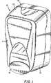
符号10により総括的に示されている分与器が、図面の図1に示されている。種々の分与器が当業界において広く利用できるものであり、図1に示されている分与器10は一例にすぎない。分与器10は、一般に、石けんを保持する袋又はびんのような容器20(図2)を収容するハウジング11を包含する。ハウジング11は、空となった容器20の交換を容易にするためにクラムシェルのような手段で互いに解放可能に取り付けることができるベース11aとカバー11bとを包含することができる。そして、ベース11aのくぼみ15の底部面14には複数の壁掛け用穴13を設けることができる。 A dispenser, indicated generally by the
図2に示されるように、ベース11aはくぼみ15を有することができ、このくぼみ内には容器20の少なくとも一部分が受け入れる。ベース11aは、更に、シェルフ17を包含することができ、このシェルフは容器20の頸部21の両側で容器20の下に延びている一対の肩部の形とすることができる。 As shown in FIG. 2, the base 11a can have a
符号25により総括的に示されているポンプは、典型的には、容器20から石けんを分与するために、容器20に取り付けられているか又は容器20と一体に形成されている。図示されるように、ポンプ25は一対の肩部17間で容器20から下向きに延びることができる。図3及び図4を参照するに、ポンプ25は、例えば、ねじ付きキャップ22により、容器20から下向きに延びている頸部21で容器20に取り付けることができ、キャップ22はポンプ25に嵌合して頸部21に螺合する。図示されるように、ポンプ25は、キャップ22から半径方向内向きに延びている肩部23に載っている環状リブ26を包含することができる。ポンプ25のノズル27は、キャップ22から軸方向外向きに突出し、図示の例においては、上向きに動かされて、石けんを容器20から分与せしめる。 The pump, indicated generally by the
再び図2を参照するに、ノズル位置決めバー28がこのバーに形成したくぼみ29内にノズル27を受け入れるためにベース11aの底部末端に用いられていることを見ることができる。ポンプ25のノズル27を軸方向内向きに駆動せしめて、石けんを容器から吐出せしめることを可能とするために、位置決めバー28は、ノズル27と一緒に移動可能であって、軸方向に滑動可能に作ることができ、及び/又は、図示されるように、ばねに取り付けることができる。この方法において、位置決めバー28と相互作用するハンドル12(図1)は、ノズル27を動かして石けんを容器20から分与せしめるために用いることができる。図示の例において、ハンドル12はカバー11bに枢動可能に取り付けられ、またハンドル12は後方に延びているアーム(図示せず)を包含し、このアームが位置決めバー28に係合してノズル27を垂直方向に動かし、ポンプ25を駆動せしめる。 Referring again to FIG. 2, it can be seen that the
レシーバ30は、位置決めバー28の上方に設けられて、一般に、カラーキーを受け入れるように工夫されている。上述したように、既存の分与器は所定の容器20とハウジング11との間の独特の取り付けを保証するためにカラーキーを用いている。典型的には、カラーは突出キーを担持し、レシーバ30は所定のカラーキーに対して特別のキー溝を画定する。例えば、図2に示されるレシーバ30は、一例として垂直スロットの形のキー溝Kを備えて示されている。組み合うカラーキーは、このカラーキーから突出する垂直キーを有するように作られ、このキーはレシーバ30のキー溝Kと適合する。理解されるように、多種の容器20及びハウジング11をキー止めするためには、多種のキー溝構成が個々のレシーバ30のために定められる。 The
以上のことを考慮に入れて、本発明の概念によるユニバーサルカラーキーは、図面に符号40により総括的に示されている。ユニバーサルカラーキー40を詳細に説明する前に、ここにおいて用いる用語“ユニバーサル”とは、ひとつ以上のレシーバ30と一緒に使用することができるカラーキーの機能を意味することを理解すべきである。 In view of the foregoing, a universal color key according to the inventive concept is indicated generally by the
再びレシーバ30に戻るに、レシーバ30は、カラーキー40を受け入れるような形状とされているキー板31を包含することができ、例えば図2に示されているように、半円形の開口を画定するC形のキー板31を有することができ、この半円形の開口の中にカラーキー40を受け入れることができる。キー板31は、カラーキーの高さにほぼ相当する高さを有する。シェルフ32をレシーバ30に形成することができ、このシェルフはキー板31の上で後方に延びている。キー板31のように、シェルフ32も半円形とすることができる。図示の例において、シェルフ32は、半円形のくぼみ区域をだいたい形成するようにレシーバ30の頂部面33からくぼまされ、シェルフ32はキー板31の半径方向外向きに延びている。位置決めタブ35は、シェルフ32の中央部分から上向きに延びることができる。一般に、位置決めタブ35は、容器20に形成した突出部分34と相互作用することにより、使用者が容器20をくぼみ15内に位置決めすることを助けるために用いることができる。図示の例において、突出部分34は、容器20から後方に延びていると共に容器20の横方向においてカラーキー40に隣接して中央に設けられている。容器20をくぼみ15内に中心決めするために、使用者は突出部分34をタブ35間に整列せしめ、それから、突出部分34をシェルフ32に沿って後方に滑動可能に挿入せしめる。この方法において、シェルフ32は、また、容器20のための垂直支持体を提供する。 Returning to the
キーを用いることなしに、容器20をレシーバ30に関して位置決めして固定するために、ユニバーサルカラーキー40は円筒形のカラー43からそれぞれ延びている第1のフランジ41と第2のフランジ42とを包含する。これらのフランジ41及び42は、カラー43から半径方向外向きに延び、突出部分34と同様に、容器20をくぼみ15内に位置決めする働きをする。第1のフランジ41は、カラー43の底部縁44で又はこの底部縁の近くでカラー43から半径方向外向きに延びている。第2のフランジ42は、レシーバクリアランスC(図4)を画定するように第1のフランジ41から軸方向に間隔を置いている。レシーバクリアランスCは、レシーバ30の高さ、すなわち、図示の例において示されているように、キー板31の高さに相当する。この方法において、カラーキー41が挿入されると、第2のフランジ42はキー板31の上を滑動し、これに対して第1のフランジ41はキー板31の下を滑動する。カラー43の表面上には突出キーがないので、カラーキー40は、レシーバ30に用いられているいかなるキー溝Kにもかかわらず、キー板31に対して完全に挿入することができる。第1及び第2のフランジ41,42は、容器20のための支持体を提供し、また更に、容器20の軸方向移動を制限して、くぼみ15内への容器20の適正な取り付けを保証する。 In order to position and secure the
シェルフ32から上向きに延びている位置決めタブ35のためのクリアランスを提供するために、ノッチ45をカラー43の前面又は前端46のほぼ中央部で第2のフランジ42に形成することができる。また、レシーバ30の下向きに延びている構体との接触を回避するために、同様なノッチ47を第1のフランジ41に設けることができる。ノッチ45,47の両側におけるフランジ42,41の表面は、レシーバ30の突出部と相互作用することができ、これにより、カラーキー40の回転を防止して、容器20を更に固定することができる。 A
図5を参照するに、第1のフランジ41がノッチ47により2つのセグメント41a,41bに分割されていることを見ることができる。更に、第1のフランジ41は必ずしもカラー43の全周に延びていない。図5に示されるように、第1のフランジ41は、ノッチ47により中断されている180°の弧にわたって延びているカラー43の前半分の範囲内に大体制限することができる。理解されるように、しかしながら、両フランジ41,42は、一般に、カラーキー40の挿入によりレシーバ30がこれらのフランジ41,42間に軸方向に置かれるようにするために、カラー43から半径方向外向きに突出する任意の形状を有することができる。 Referring to FIG. 5, it can be seen that the
上述したように、既存するレシーバ30に対してカラーキー40の挿入を容易にするために、フランジ41,42は所定のレシーバ30の構体と適合するような形状とすることができる。例えば、第2のフランジ42は、半円形のシェルフ(くぼみ)32内に適合するようにその前縁でわん曲することができる。第1のフランジ41の縁48も、同様にわん曲することができ、これにより、両フランジ41,42は半円形の前縁を有する。 As described above, in order to facilitate the insertion of the
カラーキー40の取り扱いを容易にするために、図6に最も良く示されているように、ひとつ又はそれ以上のホルダ49をカラー43に形成することができる。これらのホルダ49は、くぼみ、へこみ又は開口、又は正の突出表面、例えば図示されるように、垂直に延びているタブとすることができる。図示の例において、ホルダ49はカラー43から後方に延びていると共に第2のフランジ42から下向きに延びている。理解されるように、ホルダ49は、強度を加え、また、カラー43を把持するための便利な表面を提供してレシーバ30へのカラーキー40の取り付けを容易にする。その上、ホルダ49は、所定の例において、カバー11b内の表面と相互作用することにより、カラーキー40を固定するのを助ける。特に、ホルダ49の垂直表面はカラーキー40、及びそれ故ポンプ25の回転を防止するストッパとして働く。同様な方法で、第2のフランジ42は、縁42bを形成するように横方向及び半径方向外向きに延びている後部分42aを有することができ、縁42bはカバー11bと直角に接触してカラーキー40が回転に抵抗するのを助ける。このような後部分42aは任意であることを理解されよう。例えば、フランジ42は、図7−図12に示されている他の例のカラーキー140において述べるように簡単に円形とすることができる。この他の例のカラーキー140については、後で十分に説明する。 To facilitate handling of the
特に、押出し容器20がしばしば当業界において用いられており、流体が容器20から取り出されるときに、容器20内の吸引が容器20の壁を内向きに引っ張り、容器20を変形せしめる。これが起こったときに、容器が固定されていない場合には、容器の変形がポンプ25を容器20に関して回転又はよじらせしめる力を生じせしめる。この容器変形又はポンプのよじれ作用は、更に、ポンプ25をレシーバ30に関して軸方向又は横方向に動かすことを生じせしめる。上述した説明からわかることができるように、フランジ41,42及びホルダ49はすべての方向においてカラーキー40を拘束する働きをなし、その結果、ポンプ25又は容器20を追い出す又は動かす上述した力は阻止され、独特なキー及びキー止め装置を必要とすることなしに、容器20を固定する。 In particular,
カラーキー40は、当分野において知られている種々の方法により容器20に取り付けることができ、この公知の方法にはカラー43を容器20の頸部21に螺合、接着又は溶接により取り付けることが含まれる。図示の例においては、カラーキー40はポンプ25の頸部にスナップ係合する。この目的のために、カラー43はポンプ25及びキャップ22を受け入れるような大きさとされた穴50を有する。それから、キャップ22の半径方向に突出するそで部分22aがカラーキー40のスナップ係合の取り付けのために都合よく用いられる。このようなそで部分22aに代えて、容器20の突出する表面を用いることができることを理解されよう。したがって、この特徴の目的のために、そで部分22aは容器20の一部分と見ることができる。この目的のために、カラーキー40はそで部分22aと係合する取り付け部材51を包含することができる。図示の例においては、一対の取り付け部材51a,51bがカラー43の頂部縁53から上向きに突出している。これらの部材51(51a,51b)は半径方向内向きに延びている表面54(図3)を包含し、これらの表面54は、カラーキー40が容器20の頸部21に対して上向きに付勢された後に、キャップ22の上に掛止する。この方法により、カラー43はキャップ22に掛止する。この方法において、カラー43の取り付けを容易にするために、軸方向下向きに延びるにつれて半径方向内向きに傾斜する内面56(図3)を、半径方向内向きに延びている表面54と頂部縁55との間に設けることができる。換言すれば、この傾斜表面56は、半径方向内向きに延びている表面54から取り付け部材51の縁55にまで半径方向外向きにかつ軸方向上向きに延び、キャップ22上のカラー43の滑動を容易にするために、取り付け部材51及びキャップ22のいずれか一方のたわみを生じせしめることができる。傾斜表面56がキャップ22を通り過ぎると、キャップ22又は取り付け部材51はそれらの元の形状に戻ることができ、これにより、聞き取れる“クリック”又は“スナップ”音を生じせしめる。 The
カラーキー40を容器20に更に固定するために、第2の半径方向内向きに延びている突出面57を、カラー43の内面に形成した、垂直に延びているリブ58に設けることができる。図3に最も良く示されているように、取り付け部材51の半径方向内向きに突出している表面54がキャップ22の頂部面22aの上に位置すると、キャップ22の下方面22bがこの第2の半径方向内向きに突出している表面57と当接し、その結果、キャップ22は表面54と表面57との間に捕らえられる。この位置において、リブ58はキャップ22及びそれ故容器20の外周部と接触し、カラーキー40を容器20に関して固定する。 To further secure the
上述したように、容器20はくぼみ15内への容器の位置決めを容易にする突出部34を有することができる。これらの突出部34は、また、容器20をカラーキー40に関して適正に方位を合わせるために用いることができる。この正しい方位を提供するために、図5及び図6に最も良く示されているように、一対の取り付け部材51a,51bは突出部34と対応するくぼみ59を包含することができる。同様に、これらの取り付け部材51a,51bは互いに間隔を置いてそれらの間にノッチ61を画定する。くぼみ59及びノッチ61の効果は、カラー43の頂部面53から軸方向外向きに延びている穴50の周囲に歯状の環状フランジを形成することにある。上述したように、突出部34はタブ35間に受け入れられるためにベース11aに向かって後方に延びることができ、したがって、くぼみ59はカラー43の前面又は前端46の中央部に設けることができる。容器20はしばしば対称に形成されているので、同様なくぼみ59を前面又は前端46のくぼみ59と直径方向に対向して形成することができる。図3に最も良く示されているように、突出部34はくぼみ59内に着座する。容器20へのカラーキー40の適正な取り付けを容易にするために、ノッチ61及びくぼみ59は、図6に示されているように、大きさ又は深さを互いに異なるようにすることができる。この方法により、カラーキー40は、突出部34を適正な大きさとしたくぼみ59内の嵌め込むことにより、迅速に方向決めすることができる。 As described above, the
使用において、カラーキー40は、上述したように、容器20に取り付けられるか又は容器20と一体の形成されている。カラーキー40を備えている容器20は、分与器10のハウジング11内に配置することができる。容器20は、種々のハウジング11のために適当な大きさとされている。同様に、ユニバーサルカラーキー40は、カラーの特殊のキーと受け入れるように普通に用いられているキー溝Kを有するキー板31の上下に差し込むのに十分な間隔を互いに置いているフランジ41,42でもって、種々のハウジング11に用いられているキー止め装置を使用しなくてもよいようにする。キー板31の平面を越えているフランジ41,42の半径方向延長部は、容器20の好ましくない軸方向移動に対しての確実なストッパを提供し、容器20を軸方向において適正に配置する働きをする。したがって、使用者は、それから、レシーバ30に形成されている特殊のキー溝Kにかまわずに、ユニバーサルカラーキー40を備えている容器20をハウジング11内に挿入することができる。 In use, the
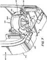
本発明の他の実施例が、図7−図12に示されている。この他の実施例は図1−図6に示した実施例に示されている部品と同じ部品を有しているので、百の位を加えた同じ符号が同じ部品を示すために用いられている。この他の例の分与器は、符号110により総括的に示されている。分与器110はベース111aを包含し、このベースの中にはポンプ装置125が受け入れられる。図7及び図8に示されているように、ポンプ125には、分与器10のレシーバ130のいかなるキー止め機構にかかわりなく容器を固定するために、符号140により総括的に示されている他の例のカラーキーを設けることができる。上述した実施例と同じように、カラーキー140は第1のフランジ141と第2のフランジ142とを有し、これらのフランジは、レシーバ30の高さに相当する距離、互いに間隔を置いている。これにより、これらのフランジ141,142は、容器を軸方向に固定するために、それらの間にレシーバ30を捕らえることができる。第1のフランジ141には、例えばベース111aのガセットGのような突出構体と適合するように、その前面又は前端146の中央部に設けたノッチ145を設けることができる。第1のフランジ141は、カラーキー140の回転がガセットG間の接触を生じさせてカラーキー140を適正な位置に保持するのに十分な範囲まで前方に延びていることができる。回転を更に防止するために、例えば図示されている垂直リブのようなホルダ149が分与器のカバーの構体と係合することができる。 Another embodiment of the present invention is shown in FIGS. Since the other embodiments have the same parts as those shown in the embodiment shown in FIGS. 1-6, the same reference numerals plus hundreds are used to indicate the same parts. Yes. This other example dispenser is indicated generally by the reference numeral 110. The dispenser 110 includes a base 111a in which a
上述した実施例と違って、第2のフランジ142の後方部分の縁142bは、分与器110のカバーの空間制限部と接触するように円形又は他の形状を有することができる。 Unlike the embodiments described above, the
図8−図12を参照するに、カラーキー140はポンプ125(図8)に取り付けられるようにされている。この目的のために、カラーキー140は穴150を有することができ、この穴はその中にポンプ125を受け入れることができる。第2のフランジ142から上向きに延びている取り付け部材151は内向きに突出しているリブ158と関連して用いられるときに、スナップ係合を提供することができる。図11及び図12を参照するに、これらのリブ158は、取り付け部材151の半径方向内向きに突出している表面154から軸方向に間隔を置いて、穴150の下部分に設けられ、これにより、ポンプ125の一部分が表面154とリブ158との間に捕らえられていることを見ることができよう。ポンプ125に取り付けられているカラーキー140は、上述した実施例において詳細に述べたように、ポンプ125及びそれ故容器の移動を制止する。 Referring to FIGS. 8-12, the
本発明の十分及び完全な説明が特許法の規定にしたがって詳述されたけれども、本発明の精神又は特許請求の範囲から逸脱することなしに、種々の変形を行うことができることを理解されよう。 Although a full and complete description of the invention has been described in detail according to the provisions of the patent law, it will be understood that various modifications can be made without departing from the spirit of the invention or the scope of the claims.
Claims (9)
Translated fromJapanesea)分与しようとする製品で充填されている容器であって、突出部分と、前記容器から下向きに延びている頸部と、前記容器から下向きに延びていると共に前記頸部で前記容器に取り付けられている又は前記容器と一体に形成されているポンプとを包含する容器と、
b)この容器を受け入れるくぼみを包含するハウジングであって、更に、前記容器の頸部を受け入れるような形状とされているキー板を有するレシーバを包含するハウジングと、
c)前記容器に取り付けられているユニバーサルカラーキーであって、前記容器により支持されているカラーを包含し、前記カラーが前記ハウジングに関してそれぞれ後方に延びている第1のフランジと第2のフランジとを有し、これらの第1及び第2のフランジがそれらの間に前記キー板を受け入れるクリアランスを画定するように互いに軸方向に間隔を置いており、前記ハウジング内への前記容器の挿入により、前記第1及び第2のフランジが前記キー板の両端で前記レシーバと軸方向に係合して、前記容器を前記ハウジング内に軸方向に固定し、前記カラーが、更に、前記カラーに形成されて前記容器の一部分を受け入れる穴と、この穴のまわりに配設されている取り付け組立体とを包含し、前記取り付け組立体が前記カラーから軸方向外向きに延びている取り付け部材から成り、前記取り付け部材がこの取り付け部材から半径方向内向きに延びて前記容器の他の一部分と係合する表面を有しているユニバーサルカラーキーと、
を包含している分与器。In the dispenser,
a) a container filled with the product to be dispensed, comprising a protruding portion, a neck extending downwardly from the container, and extending downwardly from the container and into the container at the neck A container comprising a pump attached or integrally formed with said container;
b) a housing containing a recess for receiving the container, further comprising a receiver having a key plate shaped to receive the neck of the container;
c) a universal color key attached to the container, including a collar supported by the container, the collar extending rearwardly with respect to the housing, respectively, a first flange and a second flange; And the first and second flanges are axially spaced from each other so as to define a clearance for receiving the key plate therebetween, by insertion of the container into the housing, The first and second flanges are axially engaged with the receiver at both ends of the key plate to fix the container axially in the housing, and the collar is further formed on the collar. A hole for receiving a portion of the container and a mounting assembly disposed about the hole, the mounting assembly being axially spaced from the collar. It consists attachment member extending outwardly, and a universal collar key that the mounting member has a surface which engages the other portion of the container extending radially inwardly from the mounting member,
A dispenser that contains.
Applications Claiming Priority (2)
| Application Number | Priority Date | Filing Date | Title |
|---|---|---|---|
| US10/692,906US7798370B2 (en) | 2003-10-25 | 2003-10-25 | Universal collar key |
| PCT/US2004/035450WO2005039371A1 (en) | 2003-10-25 | 2004-10-25 | Universal collar key |
Publications (3)
| Publication Number | Publication Date |
|---|---|
| JP2007508915A JP2007508915A (en) | 2007-04-12 |
| JP2007508915A5 JP2007508915A5 (en) | 2008-01-24 |
| JP4573839B2true JP4573839B2 (en) | 2010-11-04 |
Family
ID=34522234
Family Applications (1)
| Application Number | Title | Priority Date | Filing Date |
|---|---|---|---|
| JP2006536926AExpired - Fee RelatedJP4573839B2 (en) | 2003-10-25 | 2004-10-25 | Dispenser |
Country Status (15)
| Country | Link |
|---|---|
| US (1) | US7798370B2 (en) |
| EP (1) | EP1677656B1 (en) |
| JP (1) | JP4573839B2 (en) |
| KR (1) | KR101115166B1 (en) |
| CN (1) | CN100518608C (en) |
| AT (1) | ATE520335T1 (en) |
| AU (1) | AU2004283749B2 (en) |
| BR (1) | BRPI0415869A (en) |
| CA (1) | CA2542803C (en) |
| DK (1) | DK1677656T3 (en) |
| ES (1) | ES2369272T3 (en) |
| PT (1) | PT1677656E (en) |
| SG (1) | SG152280A1 (en) |
| TW (1) | TWI255173B (en) |
| WO (1) | WO2005039371A1 (en) |
Families Citing this family (34)
| Publication number | Priority date | Publication date | Assignee | Title |
|---|---|---|---|---|
| US7950548B2 (en)* | 2003-10-25 | 2011-05-31 | Gojo Industries, Inc. | Universal collar |
| BRPI0620321B1 (en) | 2005-12-22 | 2019-10-29 | Diversey Inc | lock device and method |
| GB2437510A (en)* | 2006-04-26 | 2007-10-31 | Packaging Innovation Ltd | Dispenser mechanism |
| KR100808102B1 (en) | 2006-08-23 | 2008-03-07 | 김용선 | Liquid detergent container holder |
| US9730557B2 (en) | 2007-05-16 | 2017-08-15 | Ecolab Usa Inc. | Keyed dispensing cartridge with valve insert |
| US8020733B2 (en)* | 2007-05-16 | 2011-09-20 | Ultraclenz, Llc | Keyed dispensing cartridge system |
| EP2194828B1 (en)* | 2007-09-21 | 2011-12-14 | Packaging Innovation Limited | Dispenser mechanism |
| CN101817427B (en)* | 2008-12-08 | 2014-03-12 | 哥特赫提.Com有限公司 | Dispenser for dispensing fluid |
| US8622242B2 (en) | 2010-04-16 | 2014-01-07 | Gojo Industries, Inc. | Taggant keying system for dispensing systems |
| US20120024894A1 (en)* | 2010-07-30 | 2012-02-02 | Westphal Nathan R | Dispenser |
| US8459508B2 (en) | 2010-07-30 | 2013-06-11 | S.C. Johnson & Son, Inc. | Shroud for a dispenser |
| US9340337B2 (en) | 2012-05-01 | 2016-05-17 | Ecolab Usa Inc. | Dispenser with lockable pushbutton |
| US8851331B2 (en) | 2012-05-04 | 2014-10-07 | Ecolab Usa Inc. | Fluid dispensers with adjustable dosing |
| US9204765B2 (en) | 2012-08-23 | 2015-12-08 | Gojo Industries, Inc. | Off-axis inverted foam dispensers and refill units |
| US20140054323A1 (en) | 2012-08-23 | 2014-02-27 | Gojo Industries, Inc. | Horizontal pumps, refill units and foam dispensers with integral air compressors |
| US20140054320A1 (en)* | 2012-08-23 | 2014-02-27 | Gojo Industries, Inc. | Off-axis inverted dispensers and refill units |
| US9179808B2 (en) | 2012-08-30 | 2015-11-10 | Gojo Industries, Inc. | Horizontal pumps, refill units and foam dispensers |
| US9307871B2 (en) | 2012-08-30 | 2016-04-12 | Gojo Industries, Inc. | Horizontal pumps, refill units and foam dispensers |
| WO2014078186A1 (en) | 2012-11-14 | 2014-05-22 | E. I. Du Pont De Nemours And Company | Separator media for electrochemical cells |
| US9027797B2 (en) | 2013-01-23 | 2015-05-12 | Gojo Industries, Inc. | Shield for a fluid dispenser |
| US8991655B2 (en) | 2013-02-15 | 2015-03-31 | Ecolab Usa Inc. | Fluid dispensers with increased mechanical advantage |
| US10034584B2 (en) | 2014-03-04 | 2018-07-31 | Gojo Industries, Inc. | Fluid dispenser and fluid refill system for fluid dispenser |
| WO2015179555A1 (en) | 2014-05-20 | 2015-11-26 | Gojo Industries, Inc. | Two-part fluid delivery systems |
| US11058261B2 (en) | 2015-07-15 | 2021-07-13 | Gojo Industries, Inc. | Bulk refill protection sensor for dispensing system |
| US10149575B2 (en)* | 2015-10-08 | 2018-12-11 | Gojo Industries, Inc. | Slide open refillable dispenser |
| WO2017120157A1 (en)* | 2016-01-05 | 2017-07-13 | Gojo Industries, Inc. | Systems and methods for monitoring and controlling dispenser fluid refill |
| US10278549B1 (en) | 2016-10-31 | 2019-05-07 | Gpcp Ip Holdings Llc | Counter-mounted skincare product dispenser |
| US10182685B2 (en)* | 2016-11-11 | 2019-01-22 | Op-Hygiene Ip Gmbh | Cover lift mechanism for fluid dispenser |
| CA3046681A1 (en)* | 2016-12-14 | 2018-06-21 | Gojo Industries, Inc. | Actuating mechanisms for manual dispensers |
| US10569286B2 (en) | 2017-05-08 | 2020-02-25 | Ecolab Usa Inc. | Shaped cartridge dispensing systems |
| US10561282B2 (en) | 2017-12-21 | 2020-02-18 | Speakman Company | Ligature-resistant dispenser |
| ES3015145T3 (en)* | 2020-10-14 | 2025-04-29 | Essity Hygiene & Health Ab | An adaptor assembly for a fluid dispensing system |
| US11253110B1 (en)* | 2020-10-29 | 2022-02-22 | Satellite Industries, Inc. | Dispenser for soap and sanitizer |
| US11744413B2 (en) | 2021-10-07 | 2023-09-05 | Deb Ip Limited | Dispenser assembly |
Family Cites Families (10)
| Publication number | Priority date | Publication date | Assignee | Title |
|---|---|---|---|---|
| DE2932848C2 (en)* | 1979-08-14 | 1983-09-15 | Apura GmbH + Co PWA Einmalhandtücher, 6200 Wiesbaden | Soap dispenser for liquid soaps |
| US4974753A (en)* | 1989-11-06 | 1990-12-04 | James River Corporation | Liquid dispenser container and holder system |
| IT221905Z2 (en)* | 1991-06-06 | 1994-12-06 | Q T S Srl | DISPENSER GROUP FOR LIQUID SOAP DISTRIBUTORS |
| US5464125A (en)* | 1994-06-16 | 1995-11-07 | Daansen; Warren S. | Dispensing apparatus having a pump tube |
| CH688021A5 (en) | 1994-07-18 | 1997-04-30 | Cws Ag | Apparatus for formation of soap scum and its use. |
| CA2146102C (en)* | 1995-03-31 | 2000-07-25 | Hermann Ophardt | Bag fluid dispenser |
| US5810204A (en)* | 1996-10-15 | 1998-09-22 | James River Corporation | Apparatus for dispensing liquid soap or other liquids |
| CN2402621Y (en)* | 1999-11-09 | 2000-10-25 | 谭奇锋 | Liquid packaging bottle |
| US6619509B2 (en)* | 2000-04-10 | 2003-09-16 | The Dial Corporation | Liquid dispenser |
| USD480639S1 (en)* | 2002-07-25 | 2003-10-14 | Joseph S. Kanfer | Security collar for a container closure |
- 2003
- 2003-10-25USUS10/692,906patent/US7798370B2/enactiveActive
- 2004
- 2004-10-25SGSG200902907-5Apatent/SG152280A1/enunknown
- 2004-10-25ATAT04817363Tpatent/ATE520335T1/ennot_activeIP Right Cessation
- 2004-10-25ESES04817363Tpatent/ES2369272T3/ennot_activeExpired - Lifetime
- 2004-10-25EPEP04817363Apatent/EP1677656B1/ennot_activeExpired - Lifetime
- 2004-10-25JPJP2006536926Apatent/JP4573839B2/ennot_activeExpired - Fee Related
- 2004-10-25PTPT04817363Tpatent/PT1677656E/enunknown
- 2004-10-25KRKR1020067007825Apatent/KR101115166B1/ennot_activeExpired - Fee Related
- 2004-10-25AUAU2004283749Apatent/AU2004283749B2/ennot_activeCeased
- 2004-10-25DKDK04817363.7Tpatent/DK1677656T3/enactive
- 2004-10-25CNCNB2004800315735Apatent/CN100518608C/ennot_activeExpired - Fee Related
- 2004-10-25BRBRPI0415869-5Apatent/BRPI0415869A/enactiveSearch and Examination
- 2004-10-25CACA2542803Apatent/CA2542803C/ennot_activeExpired - Fee Related
- 2004-10-25WOPCT/US2004/035450patent/WO2005039371A1/enactiveApplication Filing
- 2004-10-26TWTW093132641Apatent/TWI255173B/ennot_activeIP Right Cessation
Also Published As
| Publication number | Publication date |
|---|---|
| TW200526160A (en) | 2005-08-16 |
| CA2542803A1 (en) | 2005-05-06 |
| CN1870927A (en) | 2006-11-29 |
| PT1677656E (en) | 2011-11-08 |
| SG152280A1 (en) | 2009-05-29 |
| US7798370B2 (en) | 2010-09-21 |
| TWI255173B (en) | 2006-05-21 |
| EP1677656B1 (en) | 2011-08-17 |
| KR20060128866A (en) | 2006-12-14 |
| EP1677656A1 (en) | 2006-07-12 |
| KR101115166B1 (en) | 2012-02-27 |
| JP2007508915A (en) | 2007-04-12 |
| AU2004283749B2 (en) | 2011-06-16 |
| US20070272709A9 (en) | 2007-11-29 |
| HK1096009A1 (en) | 2007-05-25 |
| WO2005039371A1 (en) | 2005-05-06 |
| BRPI0415869A (en) | 2007-01-09 |
| CN100518608C (en) | 2009-07-29 |
| ATE520335T1 (en) | 2011-09-15 |
| DK1677656T3 (en) | 2011-10-17 |
| US20050092771A1 (en) | 2005-05-05 |
| CA2542803C (en) | 2011-12-13 |
| AU2004283749A1 (en) | 2005-05-06 |
| ES2369272T3 (en) | 2011-11-29 |
Similar Documents
| Publication | Publication Date | Title |
|---|---|---|
| JP4573839B2 (en) | Dispenser | |
| JP2007508915A5 (en) | ||
| JP4613169B2 (en) | Dispenser | |
| US8087545B2 (en) | Counter mounted dispensing system | |
| JP2007509014A5 (en) | ||
| JP4573838B2 (en) | Dispenser | |
| JP2007511257A5 (en) | ||
| HK1096009B (en) | Universal collar key | |
| US20080237263A1 (en) | Liquid Dispenser with Reservoir and Pump Attaching Mechanism | |
| HK1096008B (en) | Universal adaptor clip |
Legal Events
| Date | Code | Title | Description |
|---|---|---|---|
| A521 | Request for written amendment filed | Free format text:JAPANESE INTERMEDIATE CODE: A523 Effective date:20071025 | |
| A621 | Written request for application examination | Free format text:JAPANESE INTERMEDIATE CODE: A621 Effective date:20071025 | |
| A521 | Request for written amendment filed | Free format text:JAPANESE INTERMEDIATE CODE: A523 Effective date:20071127 | |
| A131 | Notification of reasons for refusal | Free format text:JAPANESE INTERMEDIATE CODE: A131 Effective date:20091222 | |
| A601 | Written request for extension of time | Free format text:JAPANESE INTERMEDIATE CODE: A601 Effective date:20100323 | |
| A602 | Written permission of extension of time | Free format text:JAPANESE INTERMEDIATE CODE: A602 Effective date:20100330 | |
| A521 | Request for written amendment filed | Free format text:JAPANESE INTERMEDIATE CODE: A523 Effective date:20100622 | |
| TRDD | Decision of grant or rejection written | ||
| A01 | Written decision to grant a patent or to grant a registration (utility model) | Free format text:JAPANESE INTERMEDIATE CODE: A01 Effective date:20100720 | |
| A01 | Written decision to grant a patent or to grant a registration (utility model) | Free format text:JAPANESE INTERMEDIATE CODE: A01 | |
| A61 | First payment of annual fees (during grant procedure) | Free format text:JAPANESE INTERMEDIATE CODE: A61 Effective date:20100817 | |
| R150 | Certificate of patent or registration of utility model | Free format text:JAPANESE INTERMEDIATE CODE: R150 | |
| FPAY | Renewal fee payment (event date is renewal date of database) | Free format text:PAYMENT UNTIL: 20130827 Year of fee payment:3 | |
| R250 | Receipt of annual fees | Free format text:JAPANESE INTERMEDIATE CODE: R250 | |
| R250 | Receipt of annual fees | Free format text:JAPANESE INTERMEDIATE CODE: R250 | |
| R250 | Receipt of annual fees | Free format text:JAPANESE INTERMEDIATE CODE: R250 | |
| R250 | Receipt of annual fees | Free format text:JAPANESE INTERMEDIATE CODE: R250 | |
| LAPS | Cancellation because of no payment of annual fees |