JP4573783B2 - Plant control apparatus and control method, thermal power plant and control method therefor - Google Patents
Plant control apparatus and control method, thermal power plant and control method thereforDownload PDFInfo
- Publication number
- JP4573783B2 JP4573783B2JP2006062619AJP2006062619AJP4573783B2JP 4573783 B2JP4573783 B2JP 4573783B2JP 2006062619 AJP2006062619 AJP 2006062619AJP 2006062619 AJP2006062619 AJP 2006062619AJP 4573783 B2JP4573783 B2JP 4573783B2
- Authority
- JP
- Japan
- Prior art keywords
- value
- model
- measurement signal
- learning
- model output
- Prior art date
- Legal status (The legal status is an assumption and is not a legal conclusion. Google has not performed a legal analysis and makes no representation as to the accuracy of the status listed.)
- Expired - Fee Related
Links
Images


Classifications
- G—PHYSICS
- G05—CONTROLLING; REGULATING
- G05B—CONTROL OR REGULATING SYSTEMS IN GENERAL; FUNCTIONAL ELEMENTS OF SUCH SYSTEMS; MONITORING OR TESTING ARRANGEMENTS FOR SUCH SYSTEMS OR ELEMENTS
- G05B13/00—Adaptive control systems, i.e. systems automatically adjusting themselves to have a performance which is optimum according to some preassigned criterion
- G05B13/02—Adaptive control systems, i.e. systems automatically adjusting themselves to have a performance which is optimum according to some preassigned criterion electric
- G05B13/04—Adaptive control systems, i.e. systems automatically adjusting themselves to have a performance which is optimum according to some preassigned criterion electric involving the use of models or simulators
- G05B13/048—Adaptive control systems, i.e. systems automatically adjusting themselves to have a performance which is optimum according to some preassigned criterion electric involving the use of models or simulators using a predictor
- F—MECHANICAL ENGINEERING; LIGHTING; HEATING; WEAPONS; BLASTING
- F01—MACHINES OR ENGINES IN GENERAL; ENGINE PLANTS IN GENERAL; STEAM ENGINES
- F01K—STEAM ENGINE PLANTS; STEAM ACCUMULATORS; ENGINE PLANTS NOT OTHERWISE PROVIDED FOR; ENGINES USING SPECIAL WORKING FLUIDS OR CYCLES
- F01K13/00—General layout or general methods of operation of complete plants
- F01K13/02—Controlling, e.g. stopping or starting
- F—MECHANICAL ENGINEERING; LIGHTING; HEATING; WEAPONS; BLASTING
- F22—STEAM GENERATION
- F22B—METHODS OF STEAM GENERATION; STEAM BOILERS
- F22B35/00—Control systems for steam boilers
- F22B35/007—Control systems for waste heat boilers
- F—MECHANICAL ENGINEERING; LIGHTING; HEATING; WEAPONS; BLASTING
- F23—COMBUSTION APPARATUS; COMBUSTION PROCESSES
- F23N—REGULATING OR CONTROLLING COMBUSTION
- F23N5/00—Systems for controlling combustion
- G—PHYSICS
- G05—CONTROLLING; REGULATING
- G05B—CONTROL OR REGULATING SYSTEMS IN GENERAL; FUNCTIONAL ELEMENTS OF SUCH SYSTEMS; MONITORING OR TESTING ARRANGEMENTS FOR SUCH SYSTEMS OR ELEMENTS
- G05B13/00—Adaptive control systems, i.e. systems automatically adjusting themselves to have a performance which is optimum according to some preassigned criterion
- G05B13/02—Adaptive control systems, i.e. systems automatically adjusting themselves to have a performance which is optimum according to some preassigned criterion electric
- G05B13/0265—Adaptive control systems, i.e. systems automatically adjusting themselves to have a performance which is optimum according to some preassigned criterion electric the criterion being a learning criterion
- F—MECHANICAL ENGINEERING; LIGHTING; HEATING; WEAPONS; BLASTING
- F23—COMBUSTION APPARATUS; COMBUSTION PROCESSES
- F23N—REGULATING OR CONTROLLING COMBUSTION
- F23N2223/00—Signal processing; Details thereof
- F23N2223/48—Learning / Adaptive control
Landscapes
- Engineering & Computer Science (AREA)
- Artificial Intelligence (AREA)
- Combustion & Propulsion (AREA)
- Physics & Mathematics (AREA)
- Chemical & Material Sciences (AREA)
- Mechanical Engineering (AREA)
- General Engineering & Computer Science (AREA)
- Software Systems (AREA)
- Health & Medical Sciences (AREA)
- Computer Vision & Pattern Recognition (AREA)
- Evolutionary Computation (AREA)
- Medical Informatics (AREA)
- General Physics & Mathematics (AREA)
- Automation & Control Theory (AREA)
- Thermal Sciences (AREA)
- Feedback Control In General (AREA)
Description
Translated fromJapanese本発明は、プラントの制御装置と制御方法に関する。また、火力発電プラントとその制御方法に関する。 The present invention relates to a plant control apparatus and control method. Moreover, it is related with a thermal power plant and its control method.
プラントの制御装置では、制御対象であるプラントから得られる計測信号を処理して、制御対象に与える操作信号を算出する。制御装置には、プラント計測信号が運転目標を達成するように、操作信号を計算するアルゴリズムが実装されている。 The plant control device processes a measurement signal obtained from a plant that is a control target, and calculates an operation signal to be given to the control target. The control device is implemented with an algorithm for calculating an operation signal so that the plant measurement signal achieves an operation target.
プラントの制御に用いられている制御アルゴリズムとしては、PI(比例・積分)制御アルゴリズムがある。このアルゴリズムは、運転目標値と計測信号の偏差に比例ゲインを乗じた値に、偏差を時間積分した値を加算することによって、操作信号を導出する。また、学習アルゴリズムを用いて、プラントの操作信号を導出することも知られている。 As a control algorithm used for plant control, there is a PI (proportional / integral) control algorithm. This algorithm derives an operation signal by adding a value obtained by multiplying the deviation between the operation target value and the measurement signal by a proportional gain to a value obtained by integrating the deviation over time. It is also known to derive a plant operation signal using a learning algorithm.
一方、近年、教師なし学習の分野で、強化学習と呼ばれる手法がある。強化学習は、制御対象との試行錯誤的な相互作用を通じて、制御対象から得られる計測信号が望ましいものとなるように、制御対象に与える操作信号の生成方法を学習する学習制御の枠組みとして知られている。 On the other hand, in recent years, there is a technique called reinforcement learning in the field of unsupervised learning. Reinforcement learning is known as a learning control framework that learns how to generate operation signals given to a controlled object so that measurement signals obtained from the controlled object become desirable through trial-and-error interaction with the controlled object. ing.
強化学習では、制御対象から得られる信号を用いて計算されるスカラー量の評価値(強化学習では、報酬と呼ばれている)を手がかりに、現状態から将来までに得られる評価値の期待値が最大となるように、操作信号の生成方法を学習する。 In reinforcement learning, the expected value of the evaluation value obtained from the current state to the future using the evaluation value of the scalar quantity calculated by using the signal obtained from the control target (called reward in reinforcement learning). Learn how to generate an operation signal so that is maximized.
非特許文献1には、計測信号が運転目標値を達成した場合に正の評価値を与え、Actor-Critic、Q学習、実時間Dynamic Programmingなどのアルゴリズムを用いて、操作信号の生成方法を学習する手法が記載されている。また、その手法を発展させた方式として、Dyna−アーキテクチャと呼ばれる枠組みが紹介されている。この枠組みでは、制御装置内に制御対象を模擬するモデルを持つ。モデルは、制御対象に与える操作信号をモデル入力として取り込み、制御対象の計測信号の予測値であるモデル出力を算出する。このモデルは物理式や統計的手法を用いて構築する。また、モデル出力を用いて計算される評価値を手がかりに、モデル入力の生成方法を学習する。 Non-Patent
Dyna−アーキテクチャでは、モデル出力目標値を達成するようにモデル入力の生成方法を予め学習しておき、この学習結果に従って制御対象に印加する操作信号を決定する。 In the Dyna-architecture, a model input generation method is learned in advance so as to achieve a model output target value, and an operation signal to be applied to a control target is determined according to the learning result.
前述のプラントの制御装置を設計する際には、運転目標値及びモデル出力目標値を適切に設定する必要がある。特に、モデル出力目標値を決定する際には、以下に述べる課題を解決する必要がある。 When designing the above-described plant control device, it is necessary to appropriately set the operation target value and the model output target value. In particular, when determining the model output target value, it is necessary to solve the following problems.
前述のモデル出力が、制御対象計測信号の平均値となる場合がある。仮に、運転目標値とモデル出力目標値を同じ値に設定してしまうと、このモデル出力目標値を達成するモデル入力に従って生成した操作信号を制御対象に与えても、計測信号が運転目標を達成できない可能性がある。操作信号が一定の条件で制御対象を運転し、この時に得られる計測信号が変動するような場合には、計測信号の平均値が運転目標値以下であっても、ある時間帯では運転目標値を超えてしまう可能性がある。この場合、モデル出力が運転目標値を達成していても、計測信号は運転目標を達成していない。従って、計測信号が運転目標値を達成するためには、計測信号の変動幅を考慮してモデル出力目標値を決定する必要がある。 The model output described above may be an average value of the control target measurement signal. If the driving target value and the model output target value are set to the same value, even if the operation signal generated according to the model input that achieves this model output target value is given to the control target, the measurement signal achieves the driving target. It may not be possible. When the control signal is operated under the condition that the operation signal is constant and the measurement signal obtained at this time fluctuates, even if the average value of the measurement signal is less than or equal to the operation target value, the operation target value in a certain time zone May be exceeded. In this case, even if the model output achieves the operation target value, the measurement signal does not achieve the operation target. Therefore, in order for the measurement signal to achieve the operation target value, it is necessary to determine the model output target value in consideration of the fluctuation range of the measurement signal.
本発明の目的は、上述の課題を解決可能な運転目標値を計算する機能を備えたプラントの制御装置及び制御方法を提供することにある。 The objective of this invention is providing the control apparatus and control method of a plant provided with the function which calculates the operation target value which can solve the above-mentioned subject.
本発明は、制御対象であるプラントに与える操作信号を生成する操作信号生成部を備えた制御装置において、前記制御対象に操作信号を与えた時に得られる計測信号の値を予測するモデルと、前記制御対象から得られた計測信号と予め設定された計測信号の制限値を用いてモデル出力目標値を決定するモデル出力目標値決定手段と、前記モデルの予測結果であるモデル出力がモデル出力目標値を達成するようにモデル入力の生成方法を学習する学習手段を用いて、モデル出力目標値を達成するモデル入力の生成方法を学習した結果が保存されているデーベースを参照しながら、前記操作信号生成部において操作信号を生成するようにしたことを特徴とするプラントの制御装置にある。 The present invention provides a control device including an operation signal generation unit that generates an operation signal to be given to a plant that is a control target, a model that predicts a value of a measurement signal obtained when the operation signal is supplied to the control target, and Model output target value determining means for determining a model output target value using a measurement signal obtained from the control target and a preset limit value of the measurement signal, and the model output as a prediction result of the model is the model output target value Using the learning means for learning the model input generation method so as to achieve the above, the operation signal while referring to the database storing the result of learning the model input generation method for achieving the model output target value In the control apparatus of the plant, the operation signal is generated in the generation unit.
本発明の制御装置は、プラントの計測信号と、予め設定された計測信号の制限値を用いてモデル出力目標値を決定する機能を備えている。この機能を用いることにより、計測信号を処理し、計測信号の平均値,最大値,最小値を導出できる。 The control device of the present invention has a function of determining a model output target value using a plant measurement signal and a preset limit value of the measurement signal. By using this function, the measurement signal can be processed, and the average value, maximum value, and minimum value of the measurement signal can be derived.
計測信号が変動する場合には、計測信号の制限値から、計測信号の最大値から平均値を減算した値の絶対値を減算した値をモデル出力目標値とすることができる。 When the measurement signal fluctuates, a value obtained by subtracting the absolute value of the value obtained by subtracting the average value from the maximum value of the measurement signal from the limit value of the measurement signal can be used as the model output target value.
このモデル出力目標値を達成するモデル入力の生成方法に従って、制御対象であるプラントに与える操作信号を決定すれば、モデル出力目標値と計測信号の平均値が一致する。その結果、計測信号が変動しても、計測信号がその制限値を超えることはない。 If the operation signal to be given to the plant to be controlled is determined according to the model input generation method that achieves the model output target value, the model output target value and the average value of the measurement signal match. As a result, even if the measurement signal varies, the measurement signal does not exceed the limit value.
従って、計測信号が変動する場合でも、本発明のプラントの制御装置による操作信号をプラントに与えれば、計測信号が制限値を逸脱することを抑制できる。 Therefore, even when the measurement signal fluctuates, if the operation signal from the plant control device of the present invention is given to the plant, the measurement signal can be prevented from deviating from the limit value.
本発明では、更に以下の実施態様を提案する。 The present invention further proposes the following embodiments.
(1) 制御対象であるプラントに操作信号を与えた時に得られる計測信号の値が、前記制御対象の運転目標値を達成するように操作信号を生成する制御装置であって、前記制御対象に操作信号を与えた時に得られる計測信号の値を予測するモデルと、前記モデルの予測結果であるモデル出力がモデル出力目標値を達成するように前記モデルに与えるモデル入力の生成方法を学習する学習機能と、学習の結果に従って制御対象に与える操作信号を決定する機能を有するものにおいて、
予め設定された計測信号の制限値を保存するデータベースと、前記制御対象の計測信号を取り込む外部入力インターフェイスと、取り込んだ計測信号の値を保存する計測信号データベースと、前記計測信号データベースに保存された計測信号の平均値,最大値,最小値の少なくとも1つを計算した結果と前記計測信号の制限値を用いて前記モデル出力目標値を決定する機能を備え、決定された目標値を達成するように前記学習機能で学習するようにしたことを特徴とするプラントの制御装置。(1) A control device that generates an operation signal so that a value of a measurement signal obtained when an operation signal is given to a plant to be controlled achieves an operation target value of the control object, Learning to learn the model that predicts the value of the measurement signal obtained when the operation signal is given, and the generation method of the model input that is given to the model so that the model output that is the prediction result of the model achieves the model output target value In what has a function and the function which determines the operation signal given to a controlled object according to the result of learning,
A database that stores preset values of measurement signals, an external input interface that captures the measurement signals to be controlled, a measurement signal database that stores the values of the captured measurement signals, and the measurement signal database A function of determining the model output target value using a result of calculating at least one of an average value, a maximum value, and a minimum value of the measurement signal and a limit value of the measurement signal, so as to achieve the determined target value; A plant control apparatus characterized in that learning is performed by the learning function.
(2) 前記(1)に記載されたプラントの制御装置において、前記モデル出力目標値を決定する機能は、計測信号の最大値から平均値を減算した値の絶対値を、計測信号の制限値から減算して決定するものであることを特徴とするプラントの制御装置。 (2) In the plant control apparatus described in (1), the function of determining the model output target value is obtained by subtracting an average value from a maximum value of the measurement signal and calculating a limit value of the measurement signal. A control device for a plant, wherein the control device is determined by subtracting from the control device.
(3) 前記(1)に記載されたプラントの制御装置において、学習に用いる評価値を計算する評価値計算部を更に備え、この評価値計算部ではモデル出力目標値を達成した場合に正或いは負の評価値を算出し、前記学習機能では前記評価値の期待値を最大或いは最小とする操作方法を学習するようにしたことを特徴とするプラントの制御装置。 (3) The plant control apparatus described in (1) further includes an evaluation value calculation unit that calculates an evaluation value used for learning, and the evaluation value calculation unit is positive or negative when the model output target value is achieved. A plant control apparatus, wherein a negative evaluation value is calculated, and the learning function learns an operation method that maximizes or minimizes an expected value of the evaluation value.
(4) 前記(1)に記載されたプラントの制御装置において、計測信号の制限値を入力するためのユーザーインターフェイスを備えたことを特徴とするプラントの制御装置。 (4) The plant control apparatus according to (1), further including a user interface for inputting a limit value of the measurement signal.
(5) 制御対象であるプラントに与える操作信号を生成する操作信号生成部を備えた制御装置において、
前記制御対象に操作信号を与えた時に得られる計測信号の値を予測するモデルと、前記モデルの予測結果であるモデル出力がモデル出力目標値を達成するようにモデル入力の生成方法を学習する学習手段と、前記制御対象から得られた計測信号と予め設定された計測信号の制限値を用いてモデル出力目標値の初期値を決定するモデル出力目標値決定手段と、モデル出力目標値を増加或いは減少するモデル目標値変更手段を用いて、はじめにモデル出力目標値の初期値を達成するようにモデル入力の生成方法を学習し、次いで変更後のモデル出力目標値を達成するようにモデル入力の生成方法を学習した学習結果が保存されているデータベースを参照しながら、前記操作信号生成部において操作信号を生成するようにしたことを特徴とするプラントの制御装置。(5) In a control device including an operation signal generation unit that generates an operation signal to be given to a plant to be controlled,
Learning to learn a model input generation method that predicts the value of a measurement signal obtained when an operation signal is given to the control target, and the model output that is a prediction result of the model achieves a model output target value Means, a model output target value determining means for determining an initial value of the model output target value using a measurement signal obtained from the control object and a preset limit value of the measurement signal, and increasing the model output target value or Using the decreasing model target value changing means, first learn how to generate model input to achieve the initial model output target value, and then generate model input to achieve the changed model output target value An operation signal is generated in the operation signal generation unit while referring to a database storing learning results obtained by learning the method. Door of the control device.
(6) 制御対象であるプラントに操作信号を与えた時に得られる計測信号の値が、前記制御対象の運転目標値を達成するように操作信号を生成する制御装置であって、前記制御対象に操作信号を与えた時に得られる計測信号の値を予測するモデルと、前記モデルの予測結果であるモデル出力がモデル出力目標値を達成するように前記モデルに与えるモデル入力の生成方法を学習する学習機能と、学習の結果に従って制御対象に与える操作信号を決定する機能を有するものにおいて、
予め設定された計測信号の制限値を保存するデータベースと、前記制御対象の計測信号を取り込む外部入力インターフェイスと、取り込んだ計測信号の値を保存する計測信号データベースと、前記計測信号データベースに保存された計測信号の平均値,最大値,最小値の少なくとも1つを計算した結果と前記計測信号の制限値を用いて前記モデル出力目標値の初期値を決定する機能と、前記モデル出力が前記モデル出力目標値を達成した場合にモデル出力目標値を減少或いは増加する機能を備え、前記初期値及び変更後のモデル出力目標値を達成するように前記学習機能で学習するようにしたことを特徴とするプラントの制御装置。(6) A control device that generates an operation signal so that a value of a measurement signal obtained when an operation signal is given to a plant to be controlled achieves the operation target value of the control object, Learning to learn the model that predicts the value of the measurement signal obtained when the operation signal is given, and the generation method of the model input that is given to the model so that the model output that is the prediction result of the model achieves the model output target value In what has a function and the function which determines the operation signal given to a controlled object according to the result of learning,
A database that stores preset values of measurement signals, an external input interface that captures the measurement signals to be controlled, a measurement signal database that stores the values of the captured measurement signals, and the measurement signal database A function of determining an initial value of the model output target value using a result of calculating at least one of an average value, a maximum value, and a minimum value of the measurement signal and a limit value of the measurement signal; and the model output is the model output When the target value is achieved, the model output target value is decreased or increased, and learning is performed by the learning function so as to achieve the initial value and the changed model output target value. Plant control device.
(7) 前記(6)に記載されたプラントの制御装置において、モデル出力目標値の初期値を決定する機能は、計測信号の最大値から平均値を減算した値の絶対値を計測信号の制限値から減算して決定するものであることを特徴とするプラントの制御装置。 (7) In the plant control apparatus described in (6) above, the function of determining the initial value of the model output target value is to limit the absolute value of the value obtained by subtracting the average value from the maximum value of the measurement signal. A plant control apparatus characterized by being determined by subtracting from a value.
(8) 前記(6)に記載されたプラントの制御装置において、学習に用いる評価値を計算する評価値計算部を更に備え、この評価値計算部ではモデル出力目標値を達成した場合に正或いは負の評価値を算出し、前記学習機能では前記評価値の期待値を最大或いは最小とする操作方法を学習するようにしたことを特徴とするプラントの制御装置。 (8) The plant control apparatus described in (6) further includes an evaluation value calculation unit that calculates an evaluation value used for learning, and the evaluation value calculation unit is positive or negative when the model output target value is achieved. A plant control apparatus, wherein a negative evaluation value is calculated, and the learning function learns an operation method that maximizes or minimizes an expected value of the evaluation value.
(9) 前記(6)に記載されたプラントの制御装置において、計測信号の制限値を入力するためのユーザーインターフェイスを備えたことを特徴とするプラントの制御装置。 (9) The plant control apparatus according to (6), further including a user interface for inputting a limit value of the measurement signal.
(10) 制御対象である火力発電プラントに操作信号を与えた時に得られる計測信号の値が、制御対象の運転目標値を達成するように操作信号を生成する制御装置であって、
前記制御対象に操作信号を与えた時に得られる計測信号の値を予測するモデルと、
前記モデルの予測結果であるモデル出力が、モデル出力目標値を達成するように、前記モデルに与えるモデル入力の生成方法を学習する学習機能と、
前記学習の結果に従って制御対象に与える操作信号を決定する機能と、
予め設定された計測信号の制限値を保存するデータベースと、
前記制御対象の計測信号を取り込む外部入力インターフェイスと、
取り込んだ計測信号の値を保存する計測信号データベースと、
前記計測信号データベースに保存された計測信号の平均値,最大値,最小値の少なくとも1つを計算した結果と前記計測信号の制限値を用いて前記モデル出力目標値の初期値を決定する機能を備え、
前記外部入力インターフェイスにて火力発電プラントの計測信号のうち、少なくとも一酸化炭素濃度と窒素酸化物濃度の1つを取り込み、前記計測信号の制限値を保存するデータベースに少なくとも一酸化炭素濃度と窒素酸化物濃度の1つの環境規制値を計測信号の制限値として保存し、前記出力目標値の初期値を決定する機能では少なくとも一酸化濃度と窒素酸化物濃度のモデル出力目標値の初期値を決定し、前記学習機能にて前記初期値を達成するモデル入力の生成方法を学習し、前記操作信号を決定する機能では学習結果に従って少なくとも空気ダンパ開度の操作信号を生成するようにしたことを特徴とする火力発電プラントの制御装置。(10) A control device that generates an operation signal so that a value of a measurement signal obtained when an operation signal is given to a thermal power plant that is a control target achieves an operation target value of the control target,
A model for predicting a value of a measurement signal obtained when an operation signal is given to the control object;
A learning function for learning a method of generating a model input to be given to the model so that the model output that is a prediction result of the model achieves a model output target value;
A function of determining an operation signal to be given to a control object according to the learning result;
A database for storing preset measurement signal limits;
An external input interface for capturing the measurement target measurement signal;
A measurement signal database that stores the values of the acquired measurement signals;
A function for determining an initial value of the model output target value using a result of calculating at least one of an average value, a maximum value, and a minimum value of the measurement signal stored in the measurement signal database and a limit value of the measurement signal; Prepared,
At least one of the carbon monoxide concentration and the nitrogen oxide concentration of the measurement signal of the thermal power plant is captured by the external input interface, and at least the carbon monoxide concentration and the nitrogen oxidation are stored in the database that stores the limit value of the measurement signal. One environmental regulation value of the object concentration is stored as the limit value of the measurement signal, and the function for determining the initial value of the output target value determines at least the initial value of the model output target value of the monoxide concentration and the nitrogen oxide concentration. The learning function learns a method of generating a model input that achieves the initial value, and the function of determining the operation signal generates an operation signal of at least an air damper opening according to a learning result. Control device for thermal power plant.
(11) 制御対象である火力発電プラントに操作信号を与えた時に得られる計測信号の値が、制御対象の運転目標値を達成するように操作信号を生成する制御装置であって、
前記制御対象に操作信号を与えた時に得られる計測信号の値を予測するモデルと、
前記モデルの予測結果であるモデル出力が、モデル出力目標値を達成するように、前記モデルに与えるモデル入力の生成方法を学習する学習機能と、
前記学習の結果に従って制御対象に与える操作信号を決定する機能と、
予め設定された計測信号の制限値を保存するデータベースと、
前記制御対象の計測信号を取り込む外部入力インターフェイスと、
取り込んだ計測信号の値を保存する計測信号データベースと、
前記計測信号データベースに保存された計測信号の平均値,最大値,最小値の少なくとも1つを計算した結果と前記計測信号の制限値を用いて前記モデル出力目標値の初期値を決定する機能と、
前記モデル出力が前記モデル出力目標値を達成した場合にモデル出力目標値を減少或いは増加する機能を備え、
前記外部入力インターフェイスにて火力発電プラントの計測信号のうち、少なくとも一酸化炭素濃度と窒素酸化物濃度の1つを取り込み、前記計測信号の制限値を保存するデータベースに少なくとも一酸化炭素濃度と窒素酸化物濃度の1つの環境規制値を計測信号の制限値として保存し、前記出力目標値の初期値を決定する機能では少なくとも一酸化濃度と窒素酸化物濃度のモデル出力目標値の初期値を決定し、前記学習機能にて前記初期値を達成するモデル入力の生成方法を学習し、前記モデル出力が前記モデル出力目標値を達成した場合には、前記モデル出力目標値を減少或いは増加する機能において窒素酸化物のモデル出力目標値を減少或いは増加させた修正モデル出力目標値を決定し、前記学習機能にて前記修正モデル出力目標値を達成するモデル入力の生成方法を学習し、前記操作信号を決定する機能では学習結果に従って少なくとも空気ダンパ開度の操作信号を生成するようにしたことを特徴とする火力発電プラントの制御装置。(11) A control device that generates an operation signal so that a value of a measurement signal obtained when an operation signal is given to a thermal power plant that is a control target achieves an operation target value of the control target,
A model for predicting a value of a measurement signal obtained when an operation signal is given to the control object;
A learning function for learning a method of generating a model input to be given to the model so that the model output that is a prediction result of the model achieves a model output target value;
A function of determining an operation signal to be given to a control object according to the learning result;
A database for storing preset measurement signal limits;
An external input interface for capturing the measurement target measurement signal;
A measurement signal database that stores the values of the acquired measurement signals;
A function of determining an initial value of the model output target value using a result of calculating at least one of an average value, a maximum value, and a minimum value of the measurement signal stored in the measurement signal database and a limit value of the measurement signal; ,
A function of decreasing or increasing the model output target value when the model output achieves the model output target value;
At least one of the carbon monoxide concentration and the nitrogen oxide concentration of the measurement signal of the thermal power plant is captured by the external input interface, and at least the carbon monoxide concentration and the nitrogen oxidation are stored in the database that stores the limit value of the measurement signal. One environmental regulation value of the object concentration is stored as the limit value of the measurement signal, and the function for determining the initial value of the output target value determines at least the initial value of the model output target value of the monoxide concentration and the nitrogen oxide concentration. When learning the model input generation method that achieves the initial value by the learning function, and the model output achieves the model output target value, the function of decreasing or increasing the model output target value A corrected model output target value obtained by decreasing or increasing the model output target value of oxide is determined, and the corrected model output target value is determined by the learning function. And learning a method of generating a model input to be formed, at least the control unit of the thermal power plant to the the to generate an operation signal of the air damper opening and wherein according to the learning result is a function of determining the operation signal.
(12) 制御対象であるプラントに操作信号を与えた時に得られる計測信号の値が、前記制御対象の運転目標値を達成するように前記操作信号を生成する制御方法であって、制御対象に操作信号を与えた時に得られる計測信号の値を予測するモデルを用いて前記制御対象に操作信号を与えた時に得られる計測信号の値を予測し、モデルの予測結果であるモデル出力がモデル出力目標値を達成するように前記モデルに与えるモデル入力の生成方法を学習し、学習の結果に従って制御対象に与える操作信号を決定する制御方法において、
前記制御対象の計測信号の平均値,最大値,最小値の少なくとも1つの値と、予め設定した計測信号の制限値を用いて前記モデル出力目標値を決定し、この目標値を達成するようにモデル入力の生成方法を学習することを特徴とするプラントの制御方法。(12) A control method for generating the operation signal so that a value of a measurement signal obtained when an operation signal is given to a plant to be controlled is the operation target value of the control object, Using a model that predicts the value of the measurement signal obtained when an operation signal is given, the value of the measurement signal obtained when the operation signal is given to the control target is predicted, and the model output that is the model prediction result is the model output In a control method for learning a generation method of a model input to be given to the model so as to achieve a target value, and determining an operation signal to be given to a control object according to a learning result,
The model output target value is determined using at least one of the average value, the maximum value, and the minimum value of the measurement signal to be controlled and a preset limit value of the measurement signal, and the target value is achieved. A plant control method characterized by learning a model input generation method.
(13) 制御対象であるプラントに操作信号を与えた時に得られる計測信号の値が、前記制御対象の運転目標値を達成するように前記操作信号を生成する制御方法であって、制御対象に操作信号を与えた時に得られる計測信号の値を予測するモデルを用いて前記制御対象に操作信号を与えた時に得られる計測信号の値を予測し、モデルの予測結果であるモデル出力がモデル出力目標値を達成するように前記モデルに与えるモデル入力の生成方法を学習し、学習の結果に従って制御対象に与える操作信号を決定する制御方法において、
前記制御対象の計測信号の平均値,最大値,最小値の少なくとも1つの値と、予め設定した計測信号の制限値を用いて前記モデル出力目標値の初期値を決定し、この初期値を達成するようにモデル入力の生成方法を学習し、前記モデル出力が前記モデル出力目標値を達成した場合にモデル出力目標値を減少或いは増加し、更にその変更された目標値を達成するようにモデルの生成方法を学習することを特徴とするプラントの制御方法。(13) A control method for generating the operation signal such that a value of a measurement signal obtained when an operation signal is given to a plant that is a control target achieves the operation target value of the control target, Using a model that predicts the value of the measurement signal obtained when an operation signal is given, the value of the measurement signal obtained when the operation signal is given to the control target is predicted, and the model output that is the model prediction result is the model output In a control method for learning a generation method of a model input to be given to the model so as to achieve a target value, and determining an operation signal to be given to a control object according to a learning result,
The initial value of the model output target value is determined using at least one of the average value, the maximum value, and the minimum value of the measurement signal to be controlled, and a preset limit value of the measurement signal, and this initial value is achieved. The model output generation method, and when the model output achieves the model output target value, the model output target value is decreased or increased, and further, the model output target value is achieved to achieve the changed target value. A plant control method characterized by learning a generation method.
(14) 前記(12)に記載されたプラントの制御方法において、前記モデル出力目標値は、計測信号の最大値から平均値を減算した値の絶対値を、計測信号の制限値から減算して算出することを特徴とするプラントの制御方法。 (14) In the plant control method described in (12), the model output target value is obtained by subtracting an absolute value obtained by subtracting an average value from a maximum value of a measurement signal from a limit value of the measurement signal. A plant control method characterized by calculating.
(15) 前記(13)に記載されたプラントの制御方法において、前記モデル出力目標値の初期値は、計測信号の最大値から平均値を減算した値の絶対値を、計測信号の制限値から減算して算出することを特徴とするプラントの制御方法。 (15) In the plant control method described in (13), the initial value of the model output target value is an absolute value of a value obtained by subtracting an average value from a maximum value of the measurement signal, from a limit value of the measurement signal. A plant control method characterized by subtracting and calculating.
(16) 前記(12)に記載されたプラントの制御方法において、モデル出力がモデル出力目標値を達成した場合に正あるいは負の評価値を算出し、モデル入力の生成方法を学習する際に、前記評価値の期待値を最大或いは最小とする操作方法を学習することを特徴とするプラントの制御方法。 (16) In the plant control method described in (12) above, when the model output achieves the model output target value, a positive or negative evaluation value is calculated, and when a model input generation method is learned, A plant control method, wherein an operation method for maximizing or minimizing an expected value of the evaluation value is learned.
(17) 前記(13)に記載されたプラントの制御方法において、モデル出力がモデル出力目標値を達成した場合に正あるいは負の評価値を算出し、モデル入力の生成方法を学習する際に、前記評価値の期待値を最大或いは最小とする操作方法を学習することを特徴とするプラントの制御方法。 (17) In the plant control method described in the above (13), when the model output achieves the model output target value, the positive or negative evaluation value is calculated, and when the model input generation method is learned, A plant control method, wherein an operation method for maximizing or minimizing an expected value of the evaluation value is learned.
(18) 制御対象である火力発電プラントに操作信号を与えた時に得られる計測信号の値が、前記制御対象の運転目標値を達成するように前記操作信号を生成する制御方法であって、制御対象に操作信号を与えた時に得られる計測信号の値を予測するモデルを用いて前記制御対象に操作信号を与えた時に得られる計測信号の値を予測し、モデルの予測結果であるモデル出力がモデル出力目標値を達成するように前記モデルに与えるモデル入力の生成方法を学習し、学習の結果に従って制御対象に与える操作信号を決定する制御方法において、
前記計測信号のうち、一酸化炭素と窒素酸化物の少なくとも1つの環境規制値を制限値として設定し、
前記制限値が設定された計測信号の平均値,最大値,最小値の少なくとも1つの値と、前記制限値を用いて前記モデル出力目標値の初期値を決定し、
この初期値を達成するようにモデル入力の生成方法を学習し、この学習結果に従って少なくとも空気ダンパ開度の操作信号を生成することを特徴とする火力発電プラントの制御方法。(18) A control method for generating the operation signal so that a value of a measurement signal obtained when an operation signal is given to a thermal power plant that is a control target achieves the operation target value of the control target. Using a model that predicts the value of the measurement signal obtained when the operation signal is given to the object, the value of the measurement signal obtained when the operation signal is given to the control object is predicted, and the model output that is the model prediction result is In the control method of learning the generation method of the model input to be given to the model so as to achieve the model output target value, and determining the operation signal to be given to the controlled object according to the learning result,
Among the measurement signals, at least one environmental regulation value of carbon monoxide and nitrogen oxide is set as a limit value,
Determining an initial value of the model output target value using at least one of an average value, a maximum value, and a minimum value of the measurement signal in which the limit value is set, and the limit value;
A control method for a thermal power plant characterized by learning a model input generation method so as to achieve the initial value and generating an operation signal of at least an air damper opening according to the learning result.
本発明は、計測信号の平均値,最大値,最小値の少なくとも1つを計算した結果と、前記計測信号の制限値を用いて前記モデル出力目標値を決定する機能を備えることを特徴とする第一の発明と、前記第一の発明によって初期値を決定し、モデル出力がモデル出力目標値の初期値を達成した場合に、モデル出力目標値を減少あるいは増加する機能を備えた第二の発明に大別される。 The present invention includes a function of determining the model output target value using a result of calculating at least one of an average value, a maximum value, and a minimum value of a measurement signal and a limit value of the measurement signal. A second aspect of the invention is provided with a function of determining an initial value by the first invention and the first invention, and reducing or increasing the model output target value when the model output achieves the initial value of the model output target value. It is roughly divided into inventions.
第一の発明では、計測信号が変動する場合に、変動幅を考慮して、計測信号の制限値より小さな値にモデル出力目標値を修正することが可能であり、常に計測信号が制限値を達成できる。 In the first invention, when the measurement signal fluctuates, the model output target value can be corrected to a value smaller than the limit value of the measurement signal in consideration of the fluctuation range, and the measurement signal always has the limit value. Can be achieved.
プラントによっては、ある特定の計測信号の値を、可能な限り0に近づけることが運転目標である場合がある。仮に、モデル出力目標値を0に設定し、この値が達成不可能な値である場合には、第一の発明では、モデル入力の生成方法を学習できない事態が発生する。このような事象を回避し、適したモデル入力の生成方法を学習するには、モデル出力目標値の設定方法に工夫が必要である。 Depending on the plant, the operation target may be to bring the value of a specific measurement signal as close to 0 as possible. If the model output target value is set to 0 and this value is an unachievable value, the first invention may not be able to learn the model input generation method. In order to avoid such an event and learn a suitable model input generation method, it is necessary to devise a method for setting the model output target value.
第二の発明では、可能な限り0に近づけることが運転目標である計測信号に関して、そのモデル出力目標値の初期値はある程度大きな値であり、その値は除々に0に近づくことになる。従って、モデル出力目標値を達成するモデル入力の生成方法を学習できないという事態が発生することはない。 In the second invention, the initial value of the model output target value is somewhat large with respect to the measurement signal whose operation target is to be as close to 0 as possible, and the value gradually approaches 0. Therefore, a situation in which a method for generating a model input that achieves the model output target value cannot be learned does not occur.
以下、最良の実施形態による制御装置について、図面を参照しながら説明する。但し、本発明は以下の実施形態に限定されるものでは無い。 Hereinafter, a control apparatus according to the best embodiment will be described with reference to the drawings. However, the present invention is not limited to the following embodiments.
図1は、本実施形態に係る制御システムを、制御対象100に適用した例のブロック図である。制御対象100を制御する制御システムは、制御装置200、入力装置900、保守ツール910、画像表示装置950とで構成される。制御装置200は、外部入力インターフェイス210を介して、制御対象100からの計測信号1を取り込む。また、制御装置200では、外部出力インターフェイス220を介して、制御対象100に操作信号16を送信する。 FIG. 1 is a block diagram of an example in which the control system according to the present embodiment is applied to a
外部入力インターフェイス210で取り込んだ計測信号2は、操作信号生成部300に伝送されると共に、計測信号データベース230に保存される。また、操作信号生成部300にて生成する操作信号15は、外部出力インターフェイス220に伝送されると共に、操作信号データベース240に保存される。 The
操作信号生成部300では、学習情報データベース280に保存されている学習情報9と、制御ロジックデータベース250に保存されている制御ロジック情報6を用いて、制御対象100からの計測信号1が運転目標値を達成するように操作信号15を生成する。 In the operation
学習情報データベース280に保存される情報は、学習部400で生成される。学習部400は、モデル500及び評価値計算部600と接続される。 Information stored in the learning
モデル500は、制御対象100の特性を模擬する機能を持つ。すなわち、操作信号16を制御対象100に与え、その結果、計測信号1を得るのと同じように、モデル500を動作させるためのモデル入力12をモデル500に与え、その結果としてモデル出力13を得る。モデル出力13は、計測信号1の予測値である。このモデル500は、制御対象100の特性を模擬するものであり、物理法則に基づくモデル式、あるいは統計的手法を用いて、モデル入力12に対するモデル出力13を計算する機能を持つ。 The
評価値計算部600は、評価値計算パラメータデータベース270に保存されている評価値計算パラメータ8とモデル出力13を用いて、評価値14を生成する機能を持つ。評価値計算パラメータデータベース270に保存されている情報の一部に、モデル出力13の目標値がある。このモデル出力目標値は、第1の目標値設定部700及び第2の目標値設定部800で生成される。 Evaluation
第1の目標値設定部700は、計測信号データベース230に保存されている計測信号3と、評価値計算パラメータデータベース270に保存されている制限値信号17を用いて、第1の目標値信号4を生成する。また、第2の目標値設定部800は、計測信号データベース230に保存されている計測信号3と、評価値計算パラメータデータベース270に保存されている前回目標値信号18と、モデル出力13を用いて、第2の目標値信号5を生成する。 The first target
学習部400は、学習情報データベース280に保存されている前回学習情報11と、学習パラメータデータベース260に保存されている学習パラメータ7と、モデル出力13を用いて、モデル入力12を生成する。モデル500で計算されたモデル出力13を用いて、評価値計算部600で計算した評価値14が学習部400に入力される。学習部400では、評価値14を用いて学習情報を更新し、更新学習情報10を学習情報データベース280に送信する。 The
制御対象100であるプラントの運転員は、キーボード901とマウス902で構成される入力装置900と、画像表示装置950に接続されている保守ツール910を用いることにより、制御装置200に備えられている種々のデータベースに保存されている情報にアクセスすることができる。 The plant operator who is the
保守ツール910は、外部入力インターフェイス920と、データ送受信処理部930及び外部出力インターフェイス940で構成される。 The
入力装置900で生成した入力信号31は、外部入力インターフェイス920を介して保守ツール910に取り込まれる。データ送受信処理部930では、入力信号32の情報に従って、制御装置200に備えられているデータベース情報30を取得する。また、データ送受信処理部930では、データベース情報30を処理した結果得られる出力信号33を、外部出力インターフェイス940に送信する。出力信号34は、画像表示装置950に表示される。 The
尚、本実施形態ではデータベースが全て制御装置200の内部に配置されているが、これらを制御装置200の外部に配置することもできる。また、本実施形態では操作信号16を生成するための信号処理機能が全て制御装置200の内部に配置されているが、これらを制御装置200の外部に配置してもよい。 In the present embodiment, all the databases are arranged inside the
以下では、本発明の制御システムを火力発電プラントに適用した場合を例にとり、データベースに保存されている情報、及び信号処理機能について説明する。 Below, the case where the control system of this invention is applied to a thermal power plant is taken as an example, and the information preserve | saved in a database and a signal processing function are demonstrated.
図2は、火力発電プラントを説明する図である。まず、火力発電プラントにおける発電の仕組みについて説明する。ボイラ101には、バーナー102を介して燃料となる石炭(微粉炭)と石炭搬送用の1次空気、及び燃焼調整用の2次空気が供給される。石炭と1次空気は配管134から、2次空気は配管141から導かれる。また、2段燃焼用のアフタエアを、アフタエアポート103を介してボイラ101に投入する。このアフタエアは、配管142から導かれる。 FIG. 2 is a diagram illustrating a thermal power plant. First, the mechanism of power generation in a thermal power plant will be described. The
石炭の燃焼により発生した高温のガスは、ボイラ101の経路に沿って流れた後、エアーヒーター104を通過する。その後、排ガス処理した後、煙突を介して大気に放出される。 Hot gas generated by the combustion of coal flows along the path of the
ボイラ101を循環する給水は、給水ポンプ105を介してボイラ101に導かれ、熱交換器106においてガスにより過熱され、高温高圧の蒸気となる。尚、本実施形態では熱交換器の数を1つとしているが、熱交換器を複数個配置してもよい。 The feed water circulating through the
熱交換器106を通過した高温高圧の蒸気は、タービンガバナ107を介して蒸気タービン108に導かれる。蒸気の持つエネルギーによって蒸気タービン108を駆動し、発電機109で発電する。 The high-temperature and high-pressure steam that has passed through the
火力発電プラントには、様々な計測器が配置されており、この計測器から取得された情報は、計測信号1として制御装置200に伝送される。例えば、図2には、流量計測器150、温度計測器151、圧力計測器152、発電出力計測器153、及び濃度計測器154が図示されている。流量計測器150では、給水ポンプ105からボイラ101に供給される給水の流量を計測する。また、温度計測器151及び圧力計測器152では、蒸気タービン108に供給される蒸気の温度や圧力を計測する。発電機109で発電された電力量は、発電出力計測器153で計測する。ボイラ101を通過中のガスに含まれている成分(CO、NOxなど)の濃度に関する情報は、濃度計測器154で計測することができる。尚、一般的には、図2に図示した以外にも、多数の計測器が火力発電プラントに配置されているが、図2では省略している。 Various measuring instruments are arranged in the thermal power plant, and information acquired from the measuring instruments is transmitted to the
次に、バーナー102から投入される1次空気と2次空気、及びアフタエアポート103から投入されるアフタエアの経路について説明する。 Next, the paths of primary air and secondary air introduced from the
1次空気は、ファン120から配管130に導かれ、途中でエアーヒーター104を通過する配管132と通過しない配管131に分岐し、再び配管133にて合流し、ミル110に導かれる。エアーヒーター104を通過する空気は、ガスにより過熱される。この1次空気を用いて、ミル110において生成する微粉炭をバーナー102に搬送する。 The primary air is guided from the
2次空気及びアフタエアは、ファン121から配管140に導かれ、エアーヒーター104で過熱された後、2次空気用の配管141と、アフタエア用の配管142とに分岐し、それぞれバーナー102とアフタエアポート103に導かれる。 The secondary air and the after air are led from the
図3は、1次空気と2次空気及びアフタエアが通過する配管部、並びにエアーヒーター104の拡大図である。図3に示すように、配管には空気ダンパ160、161、162、163が配置されている。空気ダンパを操作することにより、配管における空気が通過する面積を変更することできるので、空気ダンパの操作によって配管を通過する空気流量を調整できる。 FIG. 3 is an enlarged view of the
制御装置200で生成される操作信号16を用いて、給水ポンプ105、ミル110、空気ダンパ160、161、162、163などの機器を操作する。 The
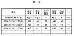
次に、計測信号データベース230、及び操作信号データベース240に保存する情報について説明する。図4及び図5は、それぞれ計測信号データベース230及び操作信号データベース240に保存されている情報の態様を説明する図である。 Next, information stored in the
図4に示すように、計測信号データベース230には、制御対象100で計測した情報が、計測器毎に各計測時刻と共に保存される。例えば、図2における流量計測器150、温度計測器151、圧力計測器152、発電出力計測器153、濃度計測器154で計測した流量値F150、温度値T151、圧力値P152、発電出力値E153、排ガスに含まれるNOx濃度D154が、時間の情報と共に保存される。尚、図4では1秒周期でデータを保存しているが、データ収集のサンプリング周期は任意に設定することが可能である。また、操作信号データベース240に保存される情報も同様に、図5に示すように給水流量の指令信号などの操作信号が、時間の情報と共に保存される。As shown in FIG. 4, information measured by the
次に、学習部400、モデル500、評価値計算部600の動作について説明する。 Next, operations of the
学習部400は、制御対象100の特性を模擬するモデル500を対象に、モデル出力13がモデル出力目標値を達成するように、モデル入力12の生成方法を学習する。学習部400では、モデル出力13を入力とした評価値計算部600の出力である評価値14を用いて、この学習を実行する。 The
このような学習を実行するアルゴリズムとして、非特許文献1に記載されている強化学習理論がある。強化学習とは、評価値(報酬)情報を手がかりに、学習部400とモデル500との相互作用を通して、モデル出力目標値を達成するためのモデル入力12の生成方法を学習することである。強化学習を適用することにより、現時刻から将来にわたって得られる評価値の期待値が最大となるようなモデル入力12の生成方法を学習することが可能である。 As an algorithm for executing such learning, there is a reinforcement learning theory described in
本実施例では、強化学習アルゴリズムとして、アクタークリティック法を適用した例について述べる。尚、本発明の制御装置200における学習方法としては、強化学習法以外に、遺伝的アルゴリズム或いは線形・非線形計画法などの最適化技術を適用することが可能である。 In this embodiment, an example in which an actor critic method is applied as a reinforcement learning algorithm will be described. As a learning method in the
図6は、アクタークリティック法の概要を説明する図である。図6のように、アクタークリティック法では、モデル入力12を生成する制御器450と、状態の価値を評価する評価器460を備える。評価器460では、モデル出力13に基づいて状態価値を計算し、評価値計算部600の出力信号である評価値14を取得し、(1)式を用いてTD誤差信号470を計算する。 FIG. 6 is a diagram for explaining the outline of the actor critic method. As shown in FIG. 6, the actor critic method includes a

ここで、δはTD誤差、γは割引率、V(s)は状態sの価値である。 Here, δ is a TD error, γ is a discount rate, and V (s) is a value of the state s.
評価器460から、制御器450に、(1)式で計算されたTD誤差信号470が伝送される。 The
図7及び図8は、アクタークリティック法のフローチャートを説明する図である。尚、本フローチャートの実行に必要な設計パラメータ(例えば割引率γ)は学習パラメータデータベース260、評価値計算パラメータデータベース270、及び学習情報データベース280に保存されている。これらのデータベースに保存されている情報の形態、及び設計パラメータをデータベースに登録する方法については後述する。 7 and 8 are diagrams for explaining a flowchart of the actor critic method. Note that design parameters (for example, discount rate γ) necessary for the execution of this flowchart are stored in the
図7に示すように、ステップ301では制御のサンプリング周期Tを取得する。次に、ステップ302では1エピソード学習を実行する。このステップ302において、学習部400、モデル500、及び評価値計算部600が動作し、前述の強化学習アルゴリズムを実行する。ステップ303では学習終了判定を実行する。これは、制御のサンプリング周期以下で学習を終了させるために設けられたステップであり、学習実行時間がTより小さい間はステップ302に戻り、Tを超えたら学習を終了する。図7のフローチャートは制御対象100を制御している間繰り返し実施される。 As shown in FIG. 7, in step 301, a control sampling period T is acquired. Next, in step 302, one episode learning is executed. In step 302, the
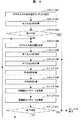
図8は、図7におけるステップ302の1エピソード学習実行時の動作を説明するフローチャートである。 FIG. 8 is a flowchart for explaining the operation at the time of execution of one episode learning in step 302 in FIG.
まずステップ401においてモデル入力の初期値をランダムに設定する。次にステップ402でステップ401にて生成したモデル入力12をモデル500に入力し、モデル出力13を得る。 First, in step 401, initial values of model inputs are set randomly. Next, in step 402, the
ステップ403では、評価値計算部600において、モデル出力13と評価値計算パラメータデータベース270に保存されているモデル出力の目標値とを比較し、モデル出力13がモデル出力目標値を達成していればエピソードを終了し、達成していない場合はステップ404に進む。 In step 403, the evaluation
ステップ404では学習部400において、学習情報データベース280に保存されている情報を用いて、モデル入力変更幅Δaを決定する。Δaの決定方法は後述する。 In step 404, the
ステップ405では、(2)式を用いてモデル入力12を決定する。 In step 405, the
ステップ406では、ステップ405で決定したモデル入力12をモデル500に入力し、モデル出力13を得る。 In step 406, the
ステップ407では、ステップ406で得たモデル出力13を用いて、評価値計算部600において評価値信号14を計算する。 In step 407, the
ステップ408では、学習情報データベース280に保存されている情報と、(1)式を用いてTD誤差を計算する。 In step 408, the TD error is calculated using the information stored in the learning
ステップ409では、ステップ408で計算したTD誤差を用いて制御器450のパラメータを更新し、その更新した結果を学習情報データベース280に保存する。 In step 409, the parameter of the
ステップ410では、ステップ408で計算したTD誤差を用いて評価器460のパラメータを更新し、その更新した結果を学習情報データベース280に保存する。 In step 410, the parameter of the
ステップ411では、ステップ403と同様の方法で終了判定を実施する。 In step 411, end determination is performed in the same manner as in step 403.
以下では、制御器450において正規乱数を用いてモデル入力12を生成し、評価器460においてタイルコーディング法を用いて状態価値を計算する場合について述べる。尚、本実施例で用いた方法以外の手法を用いて、制御器450及び評価器460を構成してもよい。 Hereinafter, a case where the
評価器460では、タイルコーディングを用いて状態を分割する。図9は、タイルコーディング法を説明する図である。タイルコーディングは、入力空間を分割し、どの領域に属するかを判別することによって、連続的な状態を離散的な状態として認識する手法である。1つ1つの領域は、タイルと呼ばれる。 The
例えば、モデル500への入力信号12が入力信号Aと入力信号Bの2次元であり、入力信号Aが0と1の間、入力信号Bが1と2の間にある場合は、図9における状態番号1のタイルに属する。学習情報データベース280には、図10に示すような形態で、状態番号と価値関数とが対応した情報が保存されている。評価器460では、モデル出力13が得られた時の入力信号12の値と、学習情報データベース280に保存されている情報を用いて、状態の価値を計算する。 For example, when the
また、評価器460では、TD誤差δ1を用いて、状態価値を(3)式に従って更新する。ここで、β1は学習率である。Further, the
図11は、ステップ404においてモデル入力変化幅を計算する方法と、ステップ409において制御器パラメータの更新方法を説明する図である。 FIG. 11 is a diagram for explaining a method for calculating the model input change width in step 404 and a method for updating the controller parameter in step 409.
図11に示した正規分布は、正規分布の中心と標準偏差の2つのパラメータを用いて発生させる。ここで、横軸はモデル入力変化幅であり、縦軸は発生確率である。従って、モデル入力変化幅は正規乱数分布に従って決定される。 The normal distribution shown in FIG. 11 is generated using two parameters, the center of the normal distribution and the standard deviation. Here, the horizontal axis is the model input change width, and the vertical axis is the occurrence probability. Therefore, the model input change width is determined according to the normal random number distribution.
次に、制御器450のパラメータの更新方法を説明する。 Next, a method for updating parameters of the
まず、ある状態において、図11(a)に示した乱数を発生させ、その乱数値に基づいてモデル入力を修正した結果、TD誤差が正であったとする。これは、このモデル入力を実行したことによって、予期していたよりもよい評価値が得られたことを意味する。そこで、次に同じ状態に到達したとき、この乱数値が選択される確率が大きくなるように、パラメータを更新する。具体的には、図11(b)に示すように中心をプラスの方向にシフトし、また、発生した乱数は標準偏差よりも内側であったので、標準偏差の値が小さくなるように更新する。 First, in a certain state, it is assumed that the random number shown in FIG. 11A is generated and the model input is corrected based on the random value, and as a result, the TD error is positive. This means that by executing this model input, an evaluation value better than expected was obtained. Therefore, when the same state is reached next, the parameter is updated so that the probability that this random value is selected is increased. Specifically, as shown in FIG. 11B, the center is shifted in the positive direction, and since the generated random number is inside the standard deviation, it is updated so that the value of the standard deviation becomes smaller. .
正規分布の中心c(St)及び標準偏差σ(St)は、それぞれ(4)式、及び(5)式に従って更新する。ここで、β2及びβ3は学習率である。The center c (St) and standard deviation σ (St) of the normal distribution are updated according to the equations (4) and (5), respectively. Here, β2 and β3 are learning rates.
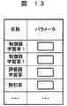
図12は、学習情報データベース280に保存されている情報であり、これは制御器450に関する情報である。前述のように、図11の正規分布を発生させるためには中心と分散の2つのパラメータが必要であり、このパラメータは状態番号毎に与えられる。このパラメータ値が、状態番号と対応づけられ、図12のような態様で学習情報データベース280に保存する。 FIG. 12 shows information stored in the learning
図13は、学習パラメータデータベース260に保存されている情報の態様を説明する図である。図13に示すように、図8のフローチャートにおけるステップ409、ステップ410を実行するのに必要な学習率などのパラメータが保存される。 FIG. 13 is a diagram for explaining an aspect of information stored in the
ステップ407では、評価値計算パラメータデータベース260とモデル出力13を用いて評価値14を生成する。 In step 407, the
強化学習では、評価値14の期待値が最大となるように、モデル入力12の生成方法を学習するので、モデル出力13がモデル出力目標値を達成した場合に、評価値14の値が大きくなることが望ましい。 In reinforcement learning, the generation method of the
このような評価値14の生成方法として、モデル出力13が、モデル出力目標値を達成した場合に正の値、例えば「1」を評価値とする方法がある。また、モデル出力目標値を達成していない場合、モデル出力目標値とモデル出力13の誤差に反比例するような関数を用いて、評価値14を計算する方法がある。さらに、これらの方法を組み合わせて評価値14を計算する方法も考えられる。 As a method for generating the
評価値計算パラメータデータベース270には、モデル出力13の目標値に関する情報が保存されている。 The evaluation value
図14は、評価値計算パラメータデータベース270に保存されている情報の態様を説明する図である。図14のように、計測信号1の制限値、要求及びモデル出力13の制御目標値が保存されている。制限値、要求は、制御対象100の運転員が設定するものであり、この設定方法については後述する。制限値は、計測信号1の制限値であり、制御対象100から得られる計測信号1が超えてはならない値である。図14に記載されている要求とは、この制限値の持つ属性であり、計測信号1が制限値以下となることが目標であるか、あるいは、計測信号1が制限値以下であり、さらに、可能な限り小さな値とすることを目標とするか、等を定義する属性である。最後に、図14に記載されている目標値とは、あるモデル入力12を設定したときのモデル出力13の目標値である。 FIG. 14 is a diagram for explaining an aspect of information stored in the evaluation value
図1における第1の目標値設定部700、及び第2の目標値設定部800を用いて、図14における運転目標値が設定される。 The driving target value in FIG. 14 is set using the first target
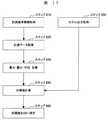
図15は、第1の目標値設定部700の動作を示すフローチャート図である。 FIG. 15 is a flowchart showing the operation of the first target
まず、ステップ710において、評価値計算パラメータデータベース270に保存されている計測信号評価項目のうち、制限値達成が目的である計測信号の項目と、その制限値を抽出する。次に、ステップ720において、ステップ710にて抽出した被制御量について、計測信号データベース230に保存されているデータを取得する。ステップ730では、ステップ720で取得したデータから、計測信号の最大値、最小値、平均値を計算する。図16は、計測信号の最大値、最小値、平均値を説明する図である。これらの値は、第1の目標値設定部700にて計算する。ステップ740では、(6)式を用いてモデル出力目標値を計算する。 First, in step 710, among the measurement signal evaluation items stored in the evaluation value
ここで、Dj(k)はモデル出力目標値、Hj(k)は制限値、Mj(k)は最大値、Aj(k)は平均値であり、kはステップ710で抽出された計測信号の項目数である。 Here, Dj (k) is the model output target value, Hj (k) is the limit value, Mj (k) is the maximum value, Aj (k) is the average value, and k is the measurement signal extracted in step 710. Number of items.
最後に、ステップ750において、(6)式で計算した目標値を、評価値計算パラメータデータベース270に保存する。 Finally, in step 750, the target value calculated by the equation (6) is stored in the evaluation value
次に、図17を用いて第2の目標値設定部800の動作を説明する。図17は、第2の目標値設定部800の動作を示すフローチャート図である。 Next, the operation of the second target
まず、ステップ810において、評価値計算パラメータデータベース270に保存されている計測信号評価項目のうち、制限値を達成し、かつ可能な限り低減することが運転の目的である計測信号の項目と、その制限値及び運転目標値を抽出する。次に、ステップ820において、ステップ810にて抽出した計測信号項目について、計測信号データベース230に保存されているデータを取得する。ステップ830では、ステップ820で取得したデータから、計測信号毎に最大値、最小値、平均値を計算する。また、ステップ840では、モデル出力13を取得する。ステップ850では、(7)式を用いてモデル出力目標値の初期値を計算する。 First, in step 810, among the measurement signal evaluation items stored in the evaluation value
ここで、Dj(k)はモデル出力目標値、Hj(k)は制限値、Mj(k)は最大値、Aj(k)は平均値であり、lはステップ810で抽出された計測信号の評価項目数である。 Here, Dj (k) is the model output target value, Hj (k) is the limit value, Mj (k) is the maximum value, Aj (k) is the average value, and l is the measurement signal extracted in step 810. The number of evaluation items.
図7のフローチャートを実行中に、モデル出力13の値がDj(k)より小さくなった場合、(8)式を用いてモデル出力目標値を小さな値に更新する。 When the value of the
ここで、ψは運転員の設定するパラメータである。 Here, ψ is a parameter set by the operator.
また、学習を実施している最中に得られたモデル出力の最小値を、モデル出力目標値に設定することもできる。 Further, the minimum value of the model output obtained during the learning can be set as the model output target value.
尚、本実施例ではモデル出力目標値を小さな値に更新する場合について述べたが、計測信号を可能な限り大きな値としたい場合には、モデル出力目標値を大きな値に更新することもできる。 Although the case where the model output target value is updated to a small value has been described in the present embodiment, the model output target value can be updated to a large value when it is desired to make the measurement signal as large as possible.
これにより、学習部400では、可能な限り低減することが目標である計測信号の項目について、この要求を満足できるようにモデル入力12の生成方法を学習することが可能となる。 As a result, the
次に、制御対象100の運転員が保守ツール910を用いて、画像表示装置950にデータベースの情報を表示させる方法について説明する。図18〜図23は、画像表示装置950に表示される画面の例である。運転員は、キーボード901、マウス902を用いてパラメータ値を入力するなどの操作を実行する。 Next, a method for causing the operator of the
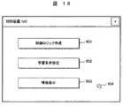
図18は、画像表示装置950に表示される初期画面である。運転員は、制御ロジック作成ボタン951、学習条件設定ボタン952、情報表示ボタン953の中から必要なボタンを選択し、マウス902を用いてカーソル954を移動させ、マウス902をクリックすることによりボタンを押す。 FIG. 18 shows an initial screen displayed on the
図19は、制御ロジック作成ボタン951をクリックした時に表示される制御ロジック編集画面である。運転員は、予め登録してある標準要素モジュール963から必要なモジュールを選び、それをロジック編集画面961へと移動させる。モジュール間は、結線/消去962を用いて接続する。図19により作成された制御ロジック図面は、保存ボタン964をクリックすることにより、データ送受信処理部930を通して制御ロジックデータベース250に保存される。操作信号生成部300では、この制御ロジック図面の情報を用いて、計測信号2が入力されたときの操作信号15を生成する。また、操作信号生成部300では、学習情報データベース280に保存されている情報を併用して、操作信号15を生成することができる。学習情報データベース280に保存されている図12の情報の状態番号と中心の情報を用いることにより、モデル出力13が望ましい値となるようなモデル入力12と同じ値を持つ操作信号15を生成できる。 FIG. 19 is a control logic editing screen displayed when the control
図19で作成した制御ロジック図面を保存しない場合には、キャンセルボタン965をクリックする。また、戻るボタン966をクリックすることにより、図18の画面に戻る。 If the control logic drawing created in FIG. 19 is not saved, a cancel
図20は、学習条件設定画面を説明する図である。図18において学習条件設定ボタン952をクリックすることにより、図20の画面が表示される。 FIG. 20 is a diagram illustrating a learning condition setting screen. When the learning
運転員は、制限値入力欄971に、被制御量とその制限値に関する情報を入力する。また、その被制御量が制限値以下となることが目的である場合は要求欄に「A」を、制限値以下になるとともに、可能な限り低減したい場合には要求欄に「B」を入力する。パラメータ設定欄972には、図7のフローチャートを実行するのに必要な設定パラメータを入力する。操作端設定欄973には、図7のフローチャートによって操作方法を学習するための操作端名称、動作範囲、及びタイルコーディングのための分割数を入力する。 The operator inputs information on the controlled variable and the limit value in the limit
図20における保存ボタン974をクリックすることにより、制限値入力欄971に入力された情報は評価値計算パラメータデータベース270に、パラメータ設定欄972に入力された情報は学習パラメータデータベース260に、操作端設定欄973に入力された情報は学習情報データベース280に保存される。 When the
キャンセルボタン975をクリックすると、制限値入力欄971、パラメータ設定欄972、操作端設定欄973に入力された情報がキャンセルされる。また、戻るボタン976をクリックすることにより、図18の画面に戻る。 When a cancel
図21は、計測信号データベース230及び操作信号データベース240に保存されている情報を画像表示装置950に表示させるため、その条件を設定する画面である。図18において、情報表示ボタン953をクリックすることにより図21が表示される。 FIG. 21 is a screen for setting conditions for displaying information stored in the
運転員は、画像表示装置950に表示させたい計測信号或いは操作信号を、入力欄981に、そのレンジ(上限/下限)と共に入力する。また、表示させたい時間を時刻入力欄982に入力する。 The operator inputs a measurement signal or an operation signal to be displayed on the
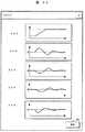
表示ボタン983をクリックすることにより、図22に示すようにトレンドグラフが画像表示装置950に表示される。図22の戻るボタン991をクリックすることにより、図21の画面に戻る。 By clicking the
また、図21において、戻るボタン984をクリックすることにより、図18の画面に戻ることができる。 In FIG. 21, the screen shown in FIG. 18 can be returned by clicking the
尚、以上で述べた画像以外にも、制御装置200内のデータベースに保存されている任意の情報を、任意の態様で画像表示装置950に表示することもできる。 In addition to the images described above, any information stored in the database in the
以下では、制御対象100が火力発電プラントである場合において、本発明の制御装置200を適用することの効果について説明する。 Below, the effect of applying the
本発明の制御装置200を用いて火力発電プラントの空気ダンパを操作することによって、CO、NOxを制御することができる。以下では、制御装置200を用いて、CO、NOxを制御することによる効果について説明する。 By operating the air damper of the thermal power plant using the
図23は、CO、NOxの基本特性を説明する図である。図23のように、一般にCOとNOxはトレードオフの関係にあり、COを低減しようとするとNOxが増加し、NOxを低減しようとするとCOが増加する。 FIG. 23 is a diagram for explaining basic characteristics of CO and NOx. As shown in FIG. 23, CO and NOx are generally in a trade-off relationship, and NOx increases when attempting to reduce CO, and CO increases when attempting to reduce NOx.
火力発電プラントの煙突から排出されるCO及びNOxには規制がかけられており、特にNOxについては、ボイラ出口のガスを脱硝装置に導き、ここでの処理を通して規制を守っている。脱硝装置に用いられるアンモニアの消費量は、脱硝装置入口のNOx濃度が高いほど多くなる。脱硝装置入口NOx量を可能な限り低減し、アンモニア消費量を抑制すれば、ランニングコストの低減につながる。 Regulations are imposed on CO and NOx discharged from the chimney of a thermal power plant. In particular, for NOx, the gas at the outlet of the boiler is guided to a denitration apparatus, and the regulation is observed through the processing here. The consumption of ammonia used in the denitration device increases as the NOx concentration at the denitration device inlet increases. If the NOx amount at the inlet of the denitration device is reduced as much as possible and the ammonia consumption is suppressed, the running cost will be reduced.
そのため、COが規制値を超えないように、かつ、NOxを可能な限り低減することが望まれている。 Therefore, it is desired to reduce NOx as much as possible so that CO does not exceed the regulation value.
図24は、制御装置200における操作信号生成部300において、学習情報データベース280に保存されている情報を用いた操作を実施する前と後について、脱硝装置入口のCO濃度とNOx濃度のトレンドを説明する図である。 FIG. 24 illustrates the trends in the CO concentration and NOx concentration at the inlet of the denitration device before and after the operation using the information stored in the learning
図24に示すように、CO及びNOxの値は、時間と共に変動する。これらの変動に関する情報は、図15のステップ730、及び図17のステップ830にて計算される。 As shown in FIG. 24, the values of CO and NOx vary with time. Information regarding these fluctuations is calculated in step 730 in FIG. 15 and step 830 in FIG.
ステップ740及びステップ840にて計算される目標値は(6)式及び(7)式で計算され、制限値から信号の最大値と平均の差を減算したものであるので、計測信号が変動しても制限値を超える可能性が低くなる。つまり、第1の目標値設定部700及び第2の目標値設定部800で計算される目標値は、計測値の変動分が考慮されたものであり、計測値が変動しても制限値を超えないようなモデル出力目標値になっている。 The target value calculated in step 740 and step 840 is calculated by the equations (6) and (7), and is obtained by subtracting the difference between the maximum value and the average of the signal from the limit value. However, the possibility of exceeding the limit value is reduced. That is, the target values calculated by the first target
これにより、操作信号生成部300で生成される操作信号15は、前述の運転目標値を満足するような制御方法に関する情報が保存されている学習情報データベース280の情報を用いて生成された信号となる。 Thus, the
従って、図24に示すように、操作後にもCOは制限値を超えることはない。さらに、NOxが操作前よりも低減するという効果が得られる。 Therefore, as shown in FIG. 24, CO does not exceed the limit value even after the operation. Furthermore, the effect that NOx is reduced than before the operation can be obtained.
100…制御対象、200…制御装置、210…外部入力インターフェイス、220…外部出力インターフェイス、230…計測信号データベース、240…操作信号データベース、250…制御ロジックデータベース、260…学習パラメータデータベース、270…評価値計算パラメータデータベース、280…学習情報データベース、300…操作信号生成部、400…学習部、500…モデル、600…評価値計算部、700…第1の目標値設定部、800…第2の目標値設定部、900…入力装置、901…キーボード、902…マウス、910…保守ツール、920…外部入力インターフェイス、930…データ送受信処理部、940…外部出力インターフェイス、950…画像表示装置。
DESCRIPTION OF
Claims (14)
Translated fromJapanese予め設定された計測信号の制限値を保存するデータベースと、前記制御対象の計測信号を取り込む外部入力インターフェイスと、取り込んだ計測信号の値を保存する計測信号データベースと、前記計測信号データベースに保存された計測信号の平均値,最大値,最小値の少なくとも1つを計算した結果と前記計測信号の制限値を用いて前記モデル出力目標値を決定する機能を備え、決定された目標値を達成するように前記学習機能で学習するとともに、前記モデル出力目標値を決定する機能は、計測信号の最大値から平均値を減算した値の絶対値を、計測信号の制限値から減算して決定するものであることを特徴とするプラントの制御装置。A control device that generates an operation signal so that a value of a measurement signal obtained when an operation signal is given to a plant to be controlled achieves the operation target value of the control object, and the operation signal is transmitted to the control object. A model for predicting a value of a measurement signal obtained when given, and a learning function for learning a generation method of a model input given to the model so that a model output that is a prediction result of the model achieves a model output target value; In what has a function which determines the operation signal given to a controlled object according to the result of learning,
A database that stores preset values of measurement signals, an external input interface that captures the measurement signals to be controlled, a measurement signal database that stores the values of the captured measurement signals, and the measurement signal database A function of determining the model output target value using a result of calculating at least one of an average value, a maximum value, and a minimum value of the measurement signal and a limit value of the measurement signal, so as to achieve the determined target value; theaddition to learning by the learningfunction, the ability to determine the model output target value, the absolute value of a value obtained by subtracting the average value from the maximum value of the measurement signal, what determines by subtracting from the limit value of the measurement signal A control device for a plant, characterized in that there is.
予め設定された計測信号の制限値を保存するデータベースと、前記制御対象の計測信号を取り込む外部入力インターフェイスと、取り込んだ計測信号の値を保存する計測信号データベースと、前記計測信号データベースに保存された計測信号の平均値,最大値,最小値の少なくとも1つを計算した結果と前記計測信号の制限値を用いて前記モデル出力目標値を決定する機能を備え、決定された目標値を達成するように前記学習機能で学習するとともに、学習に用いる評価値を計算する評価値計算部を更に備え、この評価値計算部ではモデル出力目標値を達成した場合に正或いは負の評価値を算出し、前記学習機能では前記評価値の期待値を最大或いは最小とする操作方法を学習するようにしたことを特徴とするプラントの制御装置。A control device that generates an operation signal so that a value of a measurement signal obtained when an operation signal is given to a plant to be controlled achieves the operation target value of the control object, and the operation signal is transmitted to the control object. A model for predicting a value of a measurement signal obtained when given, and a learning function for learning a generation method of a model input given to the model so that a model output that is a prediction result of the model achieves a model output target value; In what has a function which determines the operation signal given to a controlled object according to the result of learning,
A database that stores preset values of measurement signals, an external input interface that captures the measurement signals to be controlled, a measurement signal database that stores the values of the captured measurement signals, and the measurement signal database A function of determining the model output target value using a result of calculating at least one of an average value, a maximum value, and a minimum value of the measurement signal and a limit value of the measurement signal, so as to achieve the determined target value; In addition to learningwith the learning function, further comprising an evaluation value calculation unit for calculating an evaluation value used for learning, in which the evaluation value calculation unit calculates a positive or negative evaluation value when the model output target value is achieved, The plant control apparatus, wherein the learning function learns an operation method for maximizing or minimizing an expected value of the evaluation value.
計測信号の制限値を入力するためのユーザーインターフェイスを備えたことを特徴とするプラントの制御装置。In the plant control apparatus according to claim 1 or 2,
A plant control device comprising a user interface for inputting a limit value of a measurement signal.
前記制御対象に操作信号を与えた時に得られる計測信号の値を予測するモデルと、前記モデルの予測結果であるモデル出力がモデル出力目標値を達成するようにモデル入力の生成方法を学習する学習手段と、前記制御対象から得られた計測信号と予め設定された計測信号の制限値を用いてモデル出力目標値の初期値を決定するモデル出力目標値決定手段と、モデル出力目標値を増加或いは減少するモデル目標値変更手段を用いて、はじめにモデル出力目標値の初期値を達成するようにモデル入力の生成方法を学習し、次いで変更後のモデル出力目標値を達成するようにモデル入力の生成方法を学習した学習結果が保存されているデータベースを参照しながら、前記操作信号生成部において操作信号を生成するようにしたことを特徴とするプラントの制御装置。In a control device including an operation signal generation unit that generates an operation signal to be given to a plant to be controlled,
Learning to learn a model input generation method that predicts the value of a measurement signal obtained when an operation signal is given to the control target, and the model output that is a prediction result of the model achieves a model output target value Means, a model output target value determining means for determining an initial value of the model output target value using a measurement signal obtained from the control object and a preset limit value of the measurement signal, and increasing the model output target value or Using the decreasing model target value changing means, first learn how to generate model input to achieve the initial model output target value, and then generate model input to achieve the changed model output target value An operation signal is generated in the operation signal generation unit while referring to a database storing learning results obtained by learning the method. Door of the control device.
予め設定された計測信号の制限値を保存するデータベースと、前記制御対象の計測信号を取り込む外部入力インターフェイスと、取り込んだ計測信号の値を保存する計測信号データベースと、前記計測信号データベースに保存された計測信号の平均値,最大値,最小値の少なくとも1つを計算した結果と前記計測信号の制限値を用いて前記モデル出力目標値の初期値を決定する機能と、前記モデル出力が前記モデル出力目標値を達成した場合にモデル出力目標値を減少或いは増加する機能を備え、前記初期値及び変更後のモデル出力目標値を達成するように前記学習機能で学習するようにしたことを特徴とするプラントの制御装置。A control device that generates an operation signal so that a value of a measurement signal obtained when an operation signal is given to a plant to be controlled achieves the operation target value of the control object, and the operation signal is transmitted to the control object. A model for predicting a value of a measurement signal obtained when given, and a learning function for learning a generation method of a model input given to the model so that a model output that is a prediction result of the model achieves a model output target value; In what has a function which determines the operation signal given to a controlled object according to the result of learning,
A database that stores preset values of measurement signals, an external input interface that captures the measurement signals to be controlled, a measurement signal database that stores the values of the captured measurement signals, and the measurement signal database A function of determining an initial value of the model output target value using a result of calculating at least one of an average value, a maximum value, and a minimum value of the measurement signal and a limit value of the measurement signal; and the model output is the model output When the target value is achieved, the model output target value is decreased or increased, and learning is performed by the learning function so as to achieve the initial value and the changed model output target value. Plant control device.
前記制御対象に操作信号を与えた時に得られる計測信号の値を予測するモデルと、
前記モデルの予測結果であるモデル出力が、モデル出力目標値を達成するように、前記モデルに与えるモデル入力の生成方法を学習する学習機能と、
前記学習の結果に従って制御対象に与える操作信号を決定する機能と、
予め設定された計測信号の制限値を保存するデータベースと、
前記制御対象の計測信号を取り込む外部入力インターフェイスと、
取り込んだ計測信号の値を保存する計測信号データベースと、
前記計測信号データベースに保存された計測信号の平均値,最大値,最小値の少なくとも1つを計算した結果と前記計測信号の制限値を用いて前記モデル出力目標値の初期値を決定する機能と、
前記モデル出力が前記モデル出力目標値を達成した場合にモデル出力目標値を減少或いは増加する機能を備え、
前記外部入力インターフェイスにて火力発電プラントの計測信号のうち、少なくとも一酸化炭素濃度と窒素酸化物濃度の1つを取り込み、前記計測信号の制限値を保存するデータベースに少なくとも一酸化炭素濃度と窒素酸化物濃度の1つの環境規制値を計測信号の制限値として保存し、前記出力目標値の初期値を決定する機能では少なくとも一酸化濃度と窒素酸化物濃度のモデル出力目標値の初期値を決定し、前記学習機能にて前記初期値を達成するモデル入力の生成方法を学習し、前記モデル出力が前記モデル出力目標値を達成した場合には、前記モデル出力目標値を減少或いは増加する機能において窒素酸化物のモデル出力目標値を減少或いは増加させた修正モデル出力目標値を決定し、前記学習機能にて前記修正モデル出力目標値を達成するモデル入力の生成方法を学習し、前記操作信号を決定する機能では学習結果に従って少なくとも空気ダンパ開度の操作信号を生成するようにしたことを特徴とする火力発電プラントの制御装置。A control device that generates an operation signal so that a value of a measurement signal obtained when an operation signal is given to a thermal power plant that is a control target achieves an operation target value of the control target,
A model for predicting a value of a measurement signal obtained when an operation signal is given to the control object;
A learning function for learning a method of generating a model input to be given to the model so that the model output that is a prediction result of the model achieves a model output target value;
A function of determining an operation signal to be given to a control object according to the learning result;
A database for storing preset measurement signal limits;
An external input interface for capturing the measurement target measurement signal;
A measurement signal database that stores the values of the acquired measurement signals;
A function of determining an initial value of the model output target value using a result of calculating at least one of an average value, a maximum value, and a minimum value of the measurement signal stored in the measurement signal database and a limit value of the measurement signal; ,
A function of decreasing or increasing the model output target value when the model output achieves the model output target value;
At least one of the carbon monoxide concentration and the nitrogen oxide concentration of the measurement signal of the thermal power plant is captured by the external input interface, and at least the carbon monoxide concentration and the nitrogen oxidation are stored in the database that stores the limit value of the measurement signal. One environmental regulation value of the object concentration is stored as the limit value of the measurement signal, and the function for determining the initial value of the output target value determines at least the initial value of the model output target value of the monoxide concentration and the nitrogen oxide concentration. When learning the model input generation method that achieves the initial value by the learning function, and the model output achieves the model output target value, the function of decreasing or increasing the model output target value A corrected model output target value obtained by decreasing or increasing the model output target value of oxide is determined, and the corrected model output target value is determined by the learning function. And learning a method of generating a model input to be formed, at least the control unit of the thermal power plant to the the to generate an operation signal of the air damper opening and wherein according to the learning result is a function of determining the operation signal.
前記制御対象の計測信号の平均値,最大値,最小値の少なくとも1つの値と、予め設定した計測信号の制限値を用いて前記モデル出力目標値の初期値を決定し、この初期値を達成するようにモデル入力の生成方法を学習し、前記モデル出力が前記モデル出力目標値を達成した場合にモデル出力目標値を減少或いは増加し、更にその変更された目標値を達成するようにモデルの生成方法を学習することを特徴とするプラントの制御方法。A control method for generating the operation signal so that the value of the measurement signal obtained when the operation signal is given to the plant that is the control target achieves the operation target value of the control target, and the operation signal is supplied to the control target. The measurement signal value obtained when an operation signal is given to the control target is predicted using a model that predicts the measurement signal value obtained when given, and the model output as the model prediction result is the model output target value. In the control method of learning the generation method of the model input to be given to the model so as to achieve, and determining the operation signal to be given to the controlled object according to the learning result,
The initial value of the model output target value is determined using at least one of the average value, the maximum value, and the minimum value of the measurement signal to be controlled, and a preset limit value of the measurement signal, and this initial value is achieved. The model output generation method, and when the model output achieves the model output target value, the model output target value is decreased or increased, and further, the model output target value is achieved to achieve the changed target value. A plant control method characterized by learning a generation method.
前記制御対象の計測信号の平均値,最大値,最小値の少なくとも1つの値と、予め設定した計測信号の制限値を用いて前記モデル出力目標値を決定し、この目標値を達成するようにモデル入力の生成方法を学習するとともに、前記モデル出力目標値は、計測信号の最大値から平均値を減算した値の絶対値を、計測信号の制限値から減算して算出することを特徴とするプラントの制御方法。A control method for generating the operation signal so that the value of the measurement signal obtained when the operation signal is given to the plant that is the control target achieves the operation target value of the control target, and the operation signal is supplied to the control target. The measurement signal value obtained when an operation signal is given to the control target is predicted using a model that predicts the measurement signal value obtained when given, and the model output as the model prediction result is the model output target value. In the control method of learning the generation method of the model input to be given to the model so as to achieve, and determining the operation signal to be given to the controlled object according to the learning result,
The model output target value is determined using at least one of the average value, the maximum value, and the minimum value of the measurement signal to be controlled and a preset limit value of the measurement signal, and the target value is achieved. The method for generating the model input is learned, and the model output target value is calculated by subtracting the absolute value of the value obtained by subtracting the average value from the maximum value of the measurement signal from the limit value of the measurement signal. Plant control method.
前記制御対象の計測信号の平均値,最大値,最小値の少なくとも1つの値と、予め設定した計測信号の制限値を用いて前記モデル出力目標値を決定し、この目標値を達成するようにモデル入力の生成方法を学習するとともに、モデル出力がモデル出力目標値を達成した場合に正あるいは負の評価値を算出し、モデル入力の生成方法を学習する際に、前記評価値の期待値を最大或いは最小とする操作方法を学習することを特徴とするプラントの制御方法。A control method for generating the operation signal so that the value of the measurement signal obtained when the operation signal is given to the plant that is the control target achieves the operation target value of the control target, and the operation signal is supplied to the control target. The measurement signal value obtained when an operation signal is given to the control target is predicted using a model that predicts the measurement signal value obtained when given, and the model output as the model prediction result is the model output target value. In the control method of learning the generation method of the model input to be given to the model so as to achieve, and determining the operation signal to be given to the controlled object according to the learning result,
The model output target value is determined using at least one of the average value, the maximum value, and the minimum value of the measurement signal to be controlled and a preset limit value of the measurement signal, and the target value is achieved. In addition to learning how to generate the model input, calculate the positive or negative evaluation value when the model output reaches the model output target value, and when learning the model input generation method, A plant control method characterized by learning a maximum or minimum operation method.
Priority Applications (4)
| Application Number | Priority Date | Filing Date | Title |
|---|---|---|---|
| JP2006062619AJP4573783B2 (en) | 2006-03-08 | 2006-03-08 | Plant control apparatus and control method, thermal power plant and control method therefor |
| CN2006800530571ACN101379447B (en) | 2006-03-08 | 2006-12-27 | Control device and control method for equipment, thermal power plant and control method for thermal power plant |
| US12/279,348US8185216B2 (en) | 2006-03-08 | 2006-12-27 | Plant controlling device and method, thermal power plant, and its control method |
| PCT/JP2006/326111WO2007102269A1 (en) | 2006-03-08 | 2006-12-27 | Plant controlling device and method, thermal power plant, and its control method |
Applications Claiming Priority (1)
| Application Number | Priority Date | Filing Date | Title |
|---|---|---|---|
| JP2006062619AJP4573783B2 (en) | 2006-03-08 | 2006-03-08 | Plant control apparatus and control method, thermal power plant and control method therefor |
Publications (2)
| Publication Number | Publication Date |
|---|---|
| JP2007241624A JP2007241624A (en) | 2007-09-20 |
| JP4573783B2true JP4573783B2 (en) | 2010-11-04 |
Family
ID=38474711
Family Applications (1)
| Application Number | Title | Priority Date | Filing Date |
|---|---|---|---|
| JP2006062619AExpired - Fee RelatedJP4573783B2 (en) | 2006-03-08 | 2006-03-08 | Plant control apparatus and control method, thermal power plant and control method therefor |
Country Status (4)
| Country | Link |
|---|---|
| US (1) | US8185216B2 (en) |
| JP (1) | JP4573783B2 (en) |
| CN (1) | CN101379447B (en) |
| WO (1) | WO2007102269A1 (en) |
Families Citing this family (24)
| Publication number | Priority date | Publication date | Assignee | Title |
|---|---|---|---|---|
| JP4427074B2 (en) | 2007-06-07 | 2010-03-03 | 株式会社日立製作所 | Plant control equipment |
| JP4989421B2 (en)* | 2007-10-30 | 2012-08-01 | 株式会社日立製作所 | Plant control device and thermal power plant control device |
| US8135653B2 (en) | 2007-11-20 | 2012-03-13 | Hitachi, Ltd. | Power plant control device which uses a model, a learning signal, a correction signal, and a manipulation signal |
| JP4876057B2 (en)* | 2007-11-20 | 2012-02-15 | 株式会社日立製作所 | Plant control device and thermal power plant control device |
| JP5117232B2 (en)* | 2008-03-18 | 2013-01-16 | 株式会社日立製作所 | Control device for plant with boiler and control method for plant with boiler |
| JP4627553B2 (en) | 2008-03-28 | 2011-02-09 | 株式会社日立製作所 | Plant control device and thermal power plant control device |
| JP5277064B2 (en)* | 2009-04-22 | 2013-08-28 | 株式会社日立製作所 | Plant control device, thermal power plant control device, and thermal power plant |
| JP5196379B2 (en)* | 2009-06-24 | 2013-05-15 | 株式会社日立製作所 | Control device, control model adjustment device, and control model adjustment method |
| DE102010019718A1 (en)* | 2010-05-07 | 2011-11-10 | Orcan Energy Gmbh | Control of a thermal cycle |
| JP5503563B2 (en)* | 2011-01-05 | 2014-05-28 | 株式会社日立製作所 | Plant control device and thermal power plant control device |
| JP5914870B2 (en)* | 2012-06-28 | 2016-05-11 | パナソニックIpマネジメント株式会社 | Fluid measuring device |
| JP6173152B2 (en)* | 2013-09-30 | 2017-08-02 | 三浦工業株式会社 | Exhaust gas boiler with denitration equipment |
| JP6204137B2 (en)* | 2013-09-30 | 2017-09-27 | 三浦工業株式会社 | Exhaust gas boiler with denitration equipment |
| DE102013112896A1 (en)* | 2013-11-22 | 2015-05-28 | Mitsubishi Hitachi Power Systems Europe Gmbh | Method, system and computer program product for analyzing production and / or process engineering processes and / or process steps in a plant |
| JP6204204B2 (en)* | 2014-01-20 | 2017-09-27 | 中国電力株式会社 | Boiler fuel input amount determination device |
| JP6947029B2 (en)* | 2015-06-18 | 2021-10-13 | 日本電気株式会社 | Control devices, information processing devices that use them, control methods, and computer programs |
| JP6059375B1 (en) | 2016-02-09 | 2017-01-11 | ファナック株式会社 | Production control system and integrated production control system |
| CN105867128B (en)* | 2016-04-18 | 2019-10-15 | 中国神华能源股份有限公司 | A kind of lack of balance Deviation Control Method, device and automatic control for thermal power plant system |
| US10235881B2 (en)* | 2017-07-28 | 2019-03-19 | Toyota Motor Engineering & Manufacturing North America, Inc. | Autonomous operation capability configuration for a vehicle |
| JP6824859B2 (en)* | 2017-10-13 | 2021-02-03 | 三菱重工業株式会社 | In-core state quantity estimation device, estimation model creation device, their programs and methods |
| JP7121506B2 (en)* | 2018-03-14 | 2022-08-18 | 株式会社日立ハイテク | SEARCHING DEVICE, SEARCHING METHOD AND PLASMA PROCESSING DEVICE |
| KR102260500B1 (en)* | 2018-12-28 | 2021-06-03 | 주식회사 경동나비엔 | Boiler and the Method for Controlling Combustion of the Boiler |
| EP4322076A1 (en)* | 2022-08-11 | 2024-02-14 | Vito NV | A method and system for characterizing thermal energy distribution in thermal energy exchange systems |
| DE102022125151A1 (en)* | 2022-09-29 | 2024-04-04 | Vaillant Gmbh | Method for controlling a fluid, control and computer program |
Family Cites Families (14)
| Publication number | Priority date | Publication date | Assignee | Title |
|---|---|---|---|---|
| JP2656637B2 (en)* | 1989-11-22 | 1997-09-24 | 株式会社日立製作所 | Process control system and power plant process control system |
| JP2907672B2 (en)* | 1993-03-12 | 1999-06-21 | 株式会社日立製作所 | Process adaptive control method and process control system |
| JPH08339204A (en) | 1995-06-09 | 1996-12-24 | Hitachi Ltd | Thermal power plant autonomous adaptive optimization control system |
| US5993194A (en)* | 1996-06-21 | 1999-11-30 | Lemelson; Jerome H. | Automatically optimized combustion control |
| JP3421552B2 (en)* | 1997-06-30 | 2003-06-30 | 株式会社東芝 | Look-up table design method and recording medium |
| JPH1153005A (en)* | 1997-08-04 | 1999-02-26 | Nippon Steel Corp | Learning method of model parameters in control system |
| US6227842B1 (en)* | 1998-12-30 | 2001-05-08 | Jerome H. Lemelson | Automatically optimized combustion control |
| JP3712329B2 (en) | 1999-02-03 | 2005-11-02 | 株式会社日立製作所 | Process control unit |
| JP3924974B2 (en)* | 1999-02-03 | 2007-06-06 | オムロン株式会社 | Control parameter determination method and apparatus |
| US6468069B2 (en)* | 1999-10-25 | 2002-10-22 | Jerome H. Lemelson | Automatically optimized combustion control |
| JP4109527B2 (en)* | 2002-10-01 | 2008-07-02 | 新日本製鐵株式会社 | Control model learning method, control model learning apparatus, computer program, and computer-readable storage medium |
| JP4188859B2 (en)* | 2004-03-05 | 2008-12-03 | 株式会社荏原製作所 | Operation control method and operation control apparatus for waste treatment plant equipment |
| US8644961B2 (en)* | 2005-12-12 | 2014-02-04 | Neuco Inc. | Model based control and estimation of mercury emissions |
| US7389151B2 (en)* | 2006-03-06 | 2008-06-17 | General Electric Company | Systems and methods for multi-level optimizing control systems for boilers |
- 2006
- 2006-03-08JPJP2006062619Apatent/JP4573783B2/ennot_activeExpired - Fee Related
- 2006-12-27WOPCT/JP2006/326111patent/WO2007102269A1/enactiveApplication Filing
- 2006-12-27CNCN2006800530571Apatent/CN101379447B/ennot_activeExpired - Fee Related
- 2006-12-27USUS12/279,348patent/US8185216B2/ennot_activeExpired - Fee Related
Also Published As
| Publication number | Publication date |
|---|---|
| CN101379447B (en) | 2012-05-16 |
| US8185216B2 (en) | 2012-05-22 |
| CN101379447A (en) | 2009-03-04 |
| JP2007241624A (en) | 2007-09-20 |
| US20090099667A1 (en) | 2009-04-16 |
| WO2007102269A1 (en) | 2007-09-13 |
Similar Documents
| Publication | Publication Date | Title |
|---|---|---|
| JP4573783B2 (en) | Plant control apparatus and control method, thermal power plant and control method therefor | |
| JP4627553B2 (en) | Plant control device and thermal power plant control device | |
| JP4427074B2 (en) | Plant control equipment | |
| JP5251938B2 (en) | Plant control device and thermal power plant control device | |
| US7219040B2 (en) | Method and system for model based control of heavy duty gas turbine | |
| JP5503563B2 (en) | Plant control device and thermal power plant control device | |
| JP4741968B2 (en) | Plant control equipment | |
| CN101221415B (en) | fire equipment control device | |
| JP4665815B2 (en) | Plant control equipment | |
| JP2008146371A (en) | Boiler plant controller | |
| JP2010146068A (en) | Control device for plant, and control device of thermal power generation plant | |
| JP5918663B2 (en) | Thermal power plant control device and control method | |
| CN101872162B (en) | Plant control device and thermal power plant control device | |
| JP5117232B2 (en) | Control device for plant with boiler and control method for plant with boiler | |
| JP5410480B2 (en) | Plant control equipment | |
| JP5378288B2 (en) | Plant control device and thermal power plant control device | |
| JP4358871B2 (en) | Boiler plant control device and operator training device | |
| KR20080080434A (en) | Control loop to regulate the combustion process | |
| JP2000222005A (en) | Process control equipment | |
| JP4333766B2 (en) | Boiler control device and control method | |
| JP5469226B2 (en) | Control unit maintenance tools |
Legal Events
| Date | Code | Title | Description |
|---|---|---|---|
| A621 | Written request for application examination | Free format text:JAPANESE INTERMEDIATE CODE: A621 Effective date:20071206 | |
| A131 | Notification of reasons for refusal | Free format text:JAPANESE INTERMEDIATE CODE: A131 Effective date:20100413 | |
| A521 | Request for written amendment filed | Free format text:JAPANESE INTERMEDIATE CODE: A523 Effective date:20100610 | |
| TRDD | Decision of grant or rejection written | ||
| A01 | Written decision to grant a patent or to grant a registration (utility model) | Free format text:JAPANESE INTERMEDIATE CODE: A01 Effective date:20100810 | |
| A01 | Written decision to grant a patent or to grant a registration (utility model) | Free format text:JAPANESE INTERMEDIATE CODE: A01 | |
| A61 | First payment of annual fees (during grant procedure) | Free format text:JAPANESE INTERMEDIATE CODE: A61 Effective date:20100817 | |
| R150 | Certificate of patent or registration of utility model | Ref document number:4573783 Country of ref document:JP Free format text:JAPANESE INTERMEDIATE CODE: R150 Free format text:JAPANESE INTERMEDIATE CODE: R150 | |
| FPAY | Renewal fee payment (event date is renewal date of database) | Free format text:PAYMENT UNTIL: 20130827 Year of fee payment:3 | |
| LAPS | Cancellation because of no payment of annual fees |