JP4572924B2 - Key switch structure - Google Patents
Key switch structureDownload PDFInfo
- Publication number
- JP4572924B2 JP4572924B2JP2007270057AJP2007270057AJP4572924B2JP 4572924 B2JP4572924 B2JP 4572924B2JP 2007270057 AJP2007270057 AJP 2007270057AJP 2007270057 AJP2007270057 AJP 2007270057AJP 4572924 B2JP4572924 B2JP 4572924B2
- Authority
- JP
- Japan
- Prior art keywords
- sheet
- light source
- membrane sheet
- disposed
- light
- Prior art date
- Legal status (The legal status is an assumption and is not a legal conclusion. Google has not performed a legal analysis and makes no representation as to the accuracy of the status listed.)
- Active
Links
Images


Classifications
- H—ELECTRICITY
- H01—ELECTRIC ELEMENTS
- H01H—ELECTRIC SWITCHES; RELAYS; SELECTORS; EMERGENCY PROTECTIVE DEVICES
- H01H3/00—Mechanisms for operating contacts
- H01H3/02—Operating parts, i.e. for operating driving mechanism by a mechanical force external to the switch
- H01H3/12—Push-buttons
- H01H3/122—Push-buttons with enlarged actuating area, e.g. of the elongated bar-type; Stabilising means therefor
- H01H3/125—Push-buttons with enlarged actuating area, e.g. of the elongated bar-type; Stabilising means therefor using a scissor mechanism as stabiliser
- H—ELECTRICITY
- H01—ELECTRIC ELEMENTS
- H01H—ELECTRIC SWITCHES; RELAYS; SELECTORS; EMERGENCY PROTECTIVE DEVICES
- H01H13/00—Switches having rectilinearly-movable operating part or parts adapted for pushing or pulling in one direction only, e.g. push-button switch
- H01H13/02—Details
- H—ELECTRICITY
- H01—ELECTRIC ELEMENTS
- H01H—ELECTRIC SWITCHES; RELAYS; SELECTORS; EMERGENCY PROTECTIVE DEVICES
- H01H11/00—Apparatus or processes specially adapted for the manufacture of electric switches
- H—ELECTRICITY
- H01—ELECTRIC ELEMENTS
- H01H—ELECTRIC SWITCHES; RELAYS; SELECTORS; EMERGENCY PROTECTIVE DEVICES
- H01H13/00—Switches having rectilinearly-movable operating part or parts adapted for pushing or pulling in one direction only, e.g. push-button switch
- H01H13/70—Switches having rectilinearly-movable operating part or parts adapted for pushing or pulling in one direction only, e.g. push-button switch having a plurality of operating members associated with different sets of contacts, e.g. keyboard
- H01H13/83—Switches having rectilinearly-movable operating part or parts adapted for pushing or pulling in one direction only, e.g. push-button switch having a plurality of operating members associated with different sets of contacts, e.g. keyboard characterised by legends, e.g. Braille, liquid crystal displays, light emitting or optical elements
- H—ELECTRICITY
- H01—ELECTRIC ELEMENTS
- H01H—ELECTRIC SWITCHES; RELAYS; SELECTORS; EMERGENCY PROTECTIVE DEVICES
- H01H9/00—Details of switching devices, not covered by groups H01H1/00 - H01H7/00
- H01H9/18—Distinguishing marks on switches, e.g. for indicating switch location in the dark; Adaptation of switches to receive distinguishing marks
- H—ELECTRICITY
- H01—ELECTRIC ELEMENTS
- H01H—ELECTRIC SWITCHES; RELAYS; SELECTORS; EMERGENCY PROTECTIVE DEVICES
- H01H2209/00—Layers
- H01H2209/024—Properties of the substrate
- H01H2209/038—Properties of the substrate transparent
- H—ELECTRICITY
- H01—ELECTRIC ELEMENTS
- H01H—ELECTRIC SWITCHES; RELAYS; SELECTORS; EMERGENCY PROTECTIVE DEVICES
- H01H2209/00—Layers
- H01H2209/046—Properties of the spacer
- H01H2209/06—Properties of the spacer transparent
- H—ELECTRICITY
- H01—ELECTRIC ELEMENTS
- H01H—ELECTRIC SWITCHES; RELAYS; SELECTORS; EMERGENCY PROTECTIVE DEVICES
- H01H2209/00—Layers
- H01H2209/068—Properties of the membrane
- H01H2209/082—Properties of the membrane transparent
- H—ELECTRICITY
- H01—ELECTRIC ELEMENTS
- H01H—ELECTRIC SWITCHES; RELAYS; SELECTORS; EMERGENCY PROTECTIVE DEVICES
- H01H2215/00—Tactile feedback
- H01H2215/004—Collapsible dome or bubble
- H01H2215/006—Only mechanical function
- H—ELECTRICITY
- H01—ELECTRIC ELEMENTS
- H01H—ELECTRIC SWITCHES; RELAYS; SELECTORS; EMERGENCY PROTECTIVE DEVICES
- H01H2219/00—Legends
- H01H2219/028—Printed information
- H01H2219/03—Printed information in transparent keyboard
- H—ELECTRICITY
- H01—ELECTRIC ELEMENTS
- H01H—ELECTRIC SWITCHES; RELAYS; SELECTORS; EMERGENCY PROTECTIVE DEVICES
- H01H2219/00—Legends
- H01H2219/054—Optical elements
- H01H2219/06—Reflector
- H—ELECTRICITY
- H01—ELECTRIC ELEMENTS
- H01H—ELECTRIC SWITCHES; RELAYS; SELECTORS; EMERGENCY PROTECTIVE DEVICES
- H01H2219/00—Legends
- H01H2219/054—Optical elements
- H01H2219/062—Light conductor
- H—ELECTRICITY
- H01—ELECTRIC ELEMENTS
- H01H—ELECTRIC SWITCHES; RELAYS; SELECTORS; EMERGENCY PROTECTIVE DEVICES
- H01H2221/00—Actuators
- H01H2221/07—Actuators transparent
Landscapes
- Engineering & Computer Science (AREA)
- Manufacturing & Machinery (AREA)
- Push-Button Switches (AREA)
- Input From Keyboards Or The Like (AREA)
Description
Translated fromJapanese本発明は、情報処理機器、測定機器、医療機器などにおける入力装置として用いられるキーボードのキースイッチ構造に関し、特に暗い環境下でも良好な操作性を確保できる照光機能を有するキースイッチ構造に関する。 The present invention relates to a key switch structure of a keyboard used as an input device in an information processing device, a measuring device, a medical device, and the like, and more particularly to a key switch structure having an illumination function that can ensure good operability even in a dark environment.
従来、暗い環境下でも良好な操作性を確保できるキーボード装置の開発が行われており、このようなキーボードは、文字や記号等が印刷されたキースイッチを構成するキートップ、リンク部材、ラバードーム、接点部を有するメンブレンシートおよびバックプレートに加え、キーボードを照光するための光源として、例えば、EL発光部やLEDが各キースイッチに対応して配置された基板あるいは導光板を有する構成となっていた。光源としてEL素子を使用してキートップ1を照光するキースイッチを開示するものとして、例えば特開2002−251937号公報(特許文献1)が挙げられる。 Conventionally, a keyboard device that can ensure good operability even in a dark environment has been developed, and such a keyboard includes a key top, a link member, and a rubber dome that constitute a key switch on which characters and symbols are printed. In addition to the membrane sheet and the back plate having a contact portion, as a light source for illuminating the keyboard, for example, an EL light emitting portion or LED has a substrate or a light guide plate arranged corresponding to each key switch It was. JP-A-2002-251937 (Patent Document 1) is an example of a key switch that illuminates the
上記特許文献1に開示されるキーボードスイッチは、弾性部材の下方に配置されたメンブレンシートの例えば下面に、光透過性シート、光透過性電極層、発光体層、背面電極層を順次形成したEL素子を配置し、発光体層から発せられた光が、メンブレンシートとEL素子の間に配設されたベース基板の貫通孔を通って押し釦(キートップ)を下方から照光するようにしたものである。
しかしながら上記特許文献1に開示される従来のキースイッチ構造においては、光源となるEL素子が付加されている構造となっているので、通常の(照光式ではない)キーボードに較べ、光源部分が余分なスペースとなり、キーボード全体の高さが高くなるという問題があった。またキーボードの高さが変わるために、パーソナルコンピュータへの実装、即ち、通常の非照光式のキーボードを照光式のキーボードに置き換えることが困難であるという問題もあった。 However, the conventional key switch structure disclosed in
さらに、光源となる部品増加に伴うコスト高という問題に加えて、光源の部品をキースイッチ部分と組み合わせる工程が追加されることになり、作業性が悪化するという問題もあった。 Furthermore, in addition to the problem of high costs associated with an increase in the number of components that serve as the light source, a process for combining the components of the light source with the key switch portion is added, resulting in a problem that workability deteriorates.
そこで本発明は、キーボードの高さを高くすることなく、通常のキーボードと外形的に互換性を実現でき、さらに照光用の新たな部材を追加することなく、コストの低減を図ったキースイッチ構造を提供することを目的とする。 Thus, the present invention provides a key switch structure that can realize external compatibility with a normal keyboard without increasing the height of the keyboard, and further reduce costs without adding a new illumination member. The purpose is to provide.
上記課題を解決するために本発明は、光透過性の抜き文字部が形成されたキートップと、接点部を具備し、光透過性を有するメンブレンシートと、前記メンブレンシートに配設された光源と、前記キートップの下部に配置されたリンク部材と、前記メンブレンシートの上部に配設され、前記リンク部材を保持するホルダーと、前記メンブレンシートの下部に配設され、光透過性を有して前記光源から発せられた光を内部で屈曲しながら全体として水平方向に透過させるとともに、前記ホルダーが固定され該ホルダーとで前記メンブレンシートを挟むように設けられるプレート部材とを備え、前記光源から発光された光は前記プレート部材の内部を屈曲しながら全体として水平方向に透過し、前記メンブレンシートを介して前記キートップの前記抜き文字部を照光することを特徴とするものである。
In order to solve the above-described problems, the present invention provides a key top provided with a light-transmitting blank character part, a membrane sheet having a contact part and having light transparency, anda light source disposed on the membrane sheet. A link member disposed at a lower portion of the key top; a holder disposed at an upper portion of the membrane sheet; and a holder for holding the link member; disposed at a lower portion of the membrane sheet; Aplate member that is configured to transmit the light emitted from the light source in a horizontal direction while being bent inside, and to be provided so that the holder is fixed and the membrane sheet is sandwiched between the holder and the light source. emitted light passes through the horizontal direction as a whole while bending the inside of the plate member, prior to the key top via the membrane sheet It is characterized in that to illuminate the outline character portions.
本発明によれば、光源をメンブレンシート又はメンブレンシートの下方に配設し、また光源から発せられた光を内部で屈曲しながら全体として水平方向に透過させるとともに、ホルダーが固定され該ホルダーとでメンブレンシートを挟むように設けられるプレート部材を配設したので、キーボードの高さが高くなることはなく、また照光化を実現するために部材の数が増加することがない効果が得られる。
According to the present invention, the light source is disposed under the membrane sheet or the membrane sheet, and thelight emitted from the light source is transmitted in the horizontal direction as a whole while being bent inside, and the holder is fixed to the holder. Since the plate members provided so as to sandwich the membrane sheet are disposed, the height of the keyboard is notincreased, and the effect that the number of members does not increase in order to achieve illuminationcan be obtained.
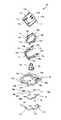
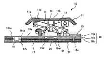
以下、本発明の実施の形態を図面にしたがって詳細に説明する。各図面に共通する要素には同一の符号を付す。図1は本発明の実施の形態のキースイッチ構造を示す分解斜視図であり、図2は本実施の形態のキースイッチ構造を示す断面図である。 Hereinafter, embodiments of the present invention will be described in detail with reference to the drawings. Elements common to the drawings are denoted by the same reference numerals. FIG. 1 is an exploded perspective view showing a key switch structure according to an embodiment of the present invention, and FIG. 2 is a cross-sectional view showing the key switch structure according to the present embodiment.
図1、図2において、実施の形態のキースイッチ10は、キートップ11と、キートップ11に対して回転可能に設けられた第1リンク部材12、キートップ11に対して摺動可能に設けられた第2リンク部材13、キートップ11が押下されることにより屈曲し、押下力が排除されるとキートップ11を元の位置に復帰させるラバードーム(弾性部材)14、第1、第2リンク部材12、13を保持するホルダー15、ラバードーム14の直下に接点部を有するメンブレンシート16、導光板の機能、即ち、透過性を有する材料により形成されたバックプレート(プレート部材)17とにより構成されている。 1 and 2, the
キートップ11は、図2に示すように、光の透過度合いを任意に調整した透明あるいは半透明の樹脂により形成された本体部11aと、本体部11aの上部に形成され、光の透過を抑えるために調整された単色または多色の塗装を施した塗装部11b、およびレーザマーキングなどで文字や記号の形に塗装を取り除くことにより、抜き文字あるいは抜き記号を形成した抜き文字部11cとを有する。なお抜き文字部11cは、キートップ11の上面に通常印刷される文字、記号、数字等をすべて含むものである。 As shown in FIG. 2, the
キートップ11の裏面には、第1リンク部材12の一端を回転可能に支持する回転支持部11dと、第2リンク部材13の一端を回転可能にかつ水平方向に移動可能に支持するスライド支持部11eが設けられている。第1リンク部材12は、一対の脚部12a、12bを有し、該脚部12a、12bの一端にはキートップ11の回転支持部11dに挿入支持される第1連結棒12cが脚部12a,12bを連結するように設けられ、同様に脚部12a,12bの他端には、第2連結棒12dが脚部12a,12bを連結するように設けられていて、更に、脚部12a,12bの各々の外面には、第1連結棒12cと第2連結棒12dとをつなぐ線上にあって、かつそれぞれの連結棒12c,12dに対して等距離となる位置に軸12e,12fが設けられている。 On the back surface of the
第2リンク部材13は一対の脚部13a,13bを有し、該脚部13a,13bの一端にはキートップ11のスライド支持部11eに回転可能にかつ水平方向に平行移動可能に支持される第1支持突起13c,13dが外側に向けて設けられ、他端には第1リンク部材12の両連結棒12c,12d間と等しい距離に第2支持突起13e,13fが外側に向けて設けられている。また、第1支持突起13c,13dと第2支持突起13e,13fをつなぐ線上にあってかつ各々の支持突起13c,13d;13e,13fに対して等距離となる位置に軸穴13g,13hが設けられている。更に、脚部13a,13bは第1支持突起13c,13dよりも先端側において連結部13iにより連結されている。 The
ラバードーム14は、ゴム等を素材として略カップ状に形成され、内面中央部に接点押下部14aが下方に向けて突出形成されている。ホルダー15は1キー単位に分割して枠状に形成され、その一端付近に第1リンク部材12の第2連結棒12dを回転可能にかつ水平方向に平行移動可能に支持するためのスライドガイド15bが設けられていて、他端付近には第2リンク部材13の第2支持突起13e,13fを回転自在に支持する回転ガイド15c,15dが設けられている。 The
またホルダー15の両端中央には、ラバードーム14の外周部を固定する円弧形のガイド壁15eが対向するように設けられ、更にホルダー15の下面にはメンブレンシート16の貫通穴16fを囲うように複数個所に所定の長さの溶着用ピン15aが形成されている。 Further, an
メンブレンシート16は、図2に示すように、それぞれ可撓性を有する上部シート16a,下部シート16bと、これらの上部シート16aと下部シート16bに挟まれたスペーサシート16cから成り、このスペーサシート16cには複数のキーに対応して複数の貫通穴16fが設けられている。貫通穴16fは上部シート16aと下部シート16bの間に空間を形成し、この空間内で互いに対向して位置するように、バックプレート17側の下部シート16bには固定接点16dが、ラバードーム14側の上部シート16aには可動接点16eがそれぞれ設けられている。 As shown in FIG. 2, the
固定接点16dおよび可動接点16eにより接点部を構成する。また図1に示すように、貫通穴16fの周囲に位置するようにメンブレンシート16に複数の透孔16gが設けられている。メンブレンシート16は全体が光透過性部材から形成されている。メンブレンシート16の上部シート16aには、後述するように、照光の光源としてのLED18が設けられている。 The fixed
バックプレート17は、以上の各部品を搭載するように下部に配置されるもので、透過性の高い樹脂により形成され、内部を光が屈曲しながら透過するようになっている。このバックプレート17にはメンブレンシート16の透孔16gに対応する位置に、ホルダー15の溶着用ピン15aを通す穴17aが貫通するように設けられている。またバックプレート17には、メンブレンシート16に設けられたLED18に対応する位置に、切り欠き穴17bが形成されている。 The
図2および図3に示すように、キースイッチ10の配置位置からずれた位置(キースイッチとキースイッチの間)において、メンブレンシート16のスペーサシート16cと下部シート16bにはそれぞれ切り欠き穴16ca、16baが形成され、この切り欠き穴16ca、16baはバックプレート17の切り欠き穴17bに対応し、これらの切り欠き穴16ca、16ba、17bに対向する上部シート16aの下部に、照光の光源としてのLED18が、発光方向が下向きになるように設けられている。LED18の高さは、スペーサシート16c、下部シート16bおよびバックプレート17を合わせた高さより小さく、したがってLED18の下部がバックプレート17の下部から下方へ突出することはない。なお図3はメンブレンシートを示す断面図である。 As shown in FIGS. 2 and 3, the
LED18は、導電性接着剤等によりメンブレンシート16の上部シート16aに固着されている。LED18は、基板を必要とせず、メンブレンシート16の接点部16d、16eのパターンと同様に印刷で接続されている。バックプレート17は、ホルダー15の溶着用ピン15aにより、メンブレンシート16を挟んでホルダー15に溶着されている。バックプレート17の、接点部16d、16eの下方の位置には、反射部20が形成されている。反射部20は円錐形状に形成され、その上面および側面は光の反射面となっている。バックプレート17の下部には反射板21が配設され、反射板21は、図2に示すように、溶着用ピン15aによる溶着部を避けて、接着等でバックプレート17に固着されている。反射板21は照射された光をバックプレート17側に反射する機能を有する。 The
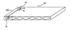
一般に、照光の光源としてのLEDを配置する場合、図4に示すように、導光板30の端部30aに集中的に配置される。このためLED18を実装するための専用のスペースが必要になる。しかしながら、キーボードの場合には全面を全て均一に照光する必要はなく、キートップ上に印刷された文字やアイコン情報を透過させれば充分であるので、本実施の形態では、図5に示すように、キースイッチとキースイッチの間にLED18を実装することにより、LED実装のための専用のスペースが不要となる。またLED18を導光板(バックプレート)17の中に埋め込んであるので、LED18を実装したために導光板(バックプレート)17が厚くなるということもない。なお図4は従来のLEDの実装状態を示す実装状態図で、図5は本実施の形態におけるLEDの実装状態を示す実装状態図である。 In general, when LEDs as an illumination light source are arranged, they are intensively arranged at the
次に動作を説明する。図2において、キートップ11を上方から任意の荷重で押下すると、キートップ11は下方に移動し、これによりラバードーム14が屈曲し、ラバードーム14の接点押下部14aが、図6に示すように、メンブレンシート16の接点部16eを押圧する。これにより接点部16eが接点部16dに接触し、スイッチ閉状態となる。また、第1リンク部材12および第2リンク部材13により、キートップ11の上部のどの部分を押下されても、キートップ11は水平状態を保ったまま下方に移動し、スイッチ閉状態が得られる。図6はスイッチ閉状態を示す断面図である。 Next, the operation will be described. In FIG. 2, when the key top 11 is pressed from above with an arbitrary load, the key top 11 moves downward, whereby the
図7は本実施の形態における照光状態を示す説明図である。図7において、メンブレンシート16に配設されたLED18が点灯されると、LED18から発せられる光は、バックプレート17の上面と反射板21との間で反射し、透明樹脂で形成されたバックプレート17の内部を屈曲しながら全体として横方向に透過する。バックプレート17を透過した光は、キートップ11の中央部の直下に形成された反射部20の上面および側面に反射する。反射部20の側面は斜めに傾斜して形成されているので、バックプレート17を通過してきた光はキートップ11方向へ反射する。 FIG. 7 is an explanatory diagram showing an illumination state in the present embodiment. In FIG. 7, when the
バックプレート17を透過した光は、メンブレンシート16が光透過性であるためにメンブレンシート16を通過する。このとき光は、メンブレンシート16に印刷された接点部16d、16eの周囲の透明部分を通過して、ラバードーム14を通過し、さらに第1リンク部材12および第2リンク部材13をすり抜けてキートップ11の裏面に到達する。キートップ11には抜き文字部11cが形成されており、この抜き文字部11cに光が照光されることにより、キートップ11上面に形成されている文字や記号の形に光って見える。 The light transmitted through the
上記実施の形態によれば、バックプレート17に導光板としての機能、即ち、高い光透過性を持たせ、光源としてのLED18をメンブレンシート16に実装したので、メンブレンシート16の一部およびバックプレート17の厚さでLED18の実装上の厚さを吸収することができ、照光部として余分な突起が発生しないので、キーボードの高さを低いままにすることができ、通常のキーボードと外形面で高い互換性を実現することができる。そのため、目的や用途に応じて、通常のキーボードと照光式のキーボードの置き換えが容易になり、使い勝手が格段に向上する。 According to the above embodiment, since the
また、バックプレート17に導光板の機能を持たせ、即ち、謂わば導光板とバックプレート17を一体化し、光源のLED18をメンブレンシート16に実装したことにより、照光用の新たな部材を追加することなく、照光式のキースイッチを実現した。このため部品点数の増加によるコスト高にならず、さらに従来と同じ工程でキーボードの製造が可能になる。 Further, the
上記実施の形態では、バックプレート17に設けた反射部20を円錐形状としたが、これに限らず、例えば、反射部を印刷の反射ドットで形成するようにしたもよい。またバックプレート17またはメンブレンシート16の上表面に凹凸形状を形成して、透過する光を拡散させるようにしてもよい。また上記実施の形態では、バックプレート17の下部に板状の反射板21を配設しているが、反射板21の代わりに、バックプレート17の下面に反射材を塗布して反射膜を形成するようにしてもよい。この場合、切り欠き穴17bの内部に反射材がかからないようにマスキングを施す。 In the above-described embodiment, the
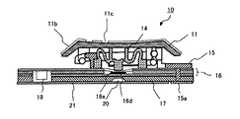
また上記実施の形態では、LED18をメンブレンシート16の上部シート16aに固着しているが、これに限らず、例えば、図8に示すように、下部シート16bの下面に下向きに設けるようにしてもよい。この場合、LED18は、バックプレート17に形成した切り欠き穴17bに位置し、LED18の厚さはバックプレート17のみで吸収することになるが、LED18は約0.2mmの厚さに作成可能であり、またバックプレート17は約0.4mm程度であるので、このような構成は可能である。 In the above embodiment, the
さらに他の変形例として、図9に示すように、メンブレンシート16とバックプレート17の間に、LED18専用のシート40を設け、LED18の厚さをバックプレート17のみで吸収するようにしてもよい。この構成にすれば、メンブレンシート16にLED18用の印刷配線をする必要がなくなるので、製造がより容易になる効果がある。 As another modification, as shown in FIG. 9, a
10 キースイッチ
11 キートップ
11c 抜き文字部
14 ラバードーム
16 メンブレンシート
17 バックプレート
18 LED
20 反射部
21 反射板10
20
Claims (10)
Translated fromJapanese接点部を具備し、光透過性を有するメンブレンシートと、
前記メンブレンシートに配設された光源と、
前記キートップの下部に配置されたリンク部材と、
前記メンブレンシートの上部に配設され、前記リンク部材を保持するホルダーと、
前記メンブレンシートの下部に配設され、光透過性を有して前記光源から発せられた光を内部で屈曲しながら全体として水平方向に透過させるとともに、前記ホルダーが固定され該ホルダーとで前記メンブレンシートを挟むように設けられるプレート部材とを備え、
前記光源から発光された光は前記プレート部材の内部を屈曲しながら全体として水平方向に透過し、前記メンブレンシートを介して前記キートップの前記抜き文字部を照光することを特徴とするキースイッチ構造。A key top on which a light-transmitting blank portion is formed; and
A membrane sheet having a contact portion and having light transparency;
A light source disposed on the membrane sheet;
A link member disposed at a lower portion of the key top;
A holder disposed on the membrane sheet and holding the link member;
The membrane sheet is disposed under the membrane sheet, has light transmission properties, and transmitslight emitted from the light source in the horizontal direction as a whole while bending the inside, and the holder is fixed to the membrane with the holder. A plate member provided so as to sandwich the sheet,
The light emitted from the light source is transmitted in the horizontal direction as a whole while bending the inside of the plate member, and illuminates the extracted character portion of the key top through the membrane sheet. .
前記光源から発光された光は、前記プレート部材を透過して前記抜き文字部へ到達する請求項1記載のキースイッチ構造。The light source is disposed on the membrane sheet so as to emit light toward the plate member,
The key switch structure according to claim 1, wherein light emitted from the light source passes through the plate member and reaches the extracted character portion.
前記光源は前記上部シートに配設される請求項1又は請求項2記載のキースイッチ構造。The membrane sheet is composed of an upper sheet, a spacer, and a lower sheet,
The key switch structure according to claim 1, wherein the light source is disposed on the upper sheet.
前記光源は、前記切り欠き部の内部に配設される請求項4記載のキースイッチ構造。A notch continuous to the spacer, the lower sheet and the plate member is formed,
The key switch structure according to claim 4, wherein the light source is disposed inside the notch.
前記光源は前記下部シートに配設される請求項1又は請求項2記載のキースイッチ構造。The membrane sheet is composed of an upper sheet, a spacer, and a lower sheet,
The key switch structure according to claim 1, wherein the light source is disposed on the lower sheet.
前記光源は、前記切り欠き部の内部に配設される請求項8記載のキースイッチ構造。A notch is formed in the plate member,
The key switch structure according to claim 8, wherein the light source is disposed inside the notch.
接点部を具備し、光透過性を有するメンブレンシートと、
前記メンブレンシートの下方に配設された光源と、
前記キートップの下部に配置されたリンク部材と、
前記メンブレンシートの上部に配設され、前記リンク部材を保持するホルダーと、
前記メンブレンシートの下部に配設され、光透過性を有して前記光源から発せられた光を内部で屈曲しながら全体として水平方向に透過させるとともに、前記ホルダーが固定され該ホルダーとで前記メンブレンシートを挟むように設けられるプレート部材と、
前記メンブレンシートと前記プレート部材の間に前記光源専用の印刷配線用の部材とを備え、
前記プレート部材の前記光源用の切り欠き部を形成し、前記光源から発光された光は前記プレート部材の内部を屈曲しながら全体として水平方向に透過し、前記メンブレンシートを介して前記キートップの前記抜き文字部を照光することを特徴とするキースイッチ構造。A key top on which a light-transmitting blank portion is formed; and
A membrane sheet having a contact portion and having light transparency;
A light source disposed below the membrane sheet;
A link member disposed at a lower portion of the key top;
A holder disposed on the membrane sheet and holding the link member;
The membrane sheet is disposed under the membrane sheet, has light transmission properties, and transmitslight emitted from the light source in the horizontal direction as a whole while bending the inside, and the holder is fixed to the membrane with the holder. A plate member provided so as to sandwich the sheet;
A member for printed wiring dedicated to the light source is provided between the membrane sheet and the plate member,
A notch for the light source of the plate member is formed, and the light emitted from the light source is transmitted in the horizontal direction as a whole while bending the inside of the plate member, and the key top of the key top is passed through the membrane sheet. A key switch structure characterized by illuminating the extracted character portion.
Priority Applications (5)
| Application Number | Priority Date | Filing Date | Title |
|---|---|---|---|
| JP2007270057AJP4572924B2 (en) | 2007-10-17 | 2007-10-17 | Key switch structure |
| KR1020080046626AKR100993759B1 (en) | 2007-10-17 | 2008-05-20 | Key switch structure |
| TW097123178ATW200919516A (en) | 2007-10-17 | 2008-06-20 | Key switch structure |
| CN2008102108316ACN101414520B (en) | 2007-10-17 | 2008-08-20 | Key switch arrangement |
| US12/232,837US20090103964A1 (en) | 2007-10-17 | 2008-09-25 | Key switch arrangement having an illuminating function |
Applications Claiming Priority (1)
| Application Number | Priority Date | Filing Date | Title |
|---|---|---|---|
| JP2007270057AJP4572924B2 (en) | 2007-10-17 | 2007-10-17 | Key switch structure |
Publications (2)
| Publication Number | Publication Date |
|---|---|
| JP2009099386A JP2009099386A (en) | 2009-05-07 |
| JP4572924B2true JP4572924B2 (en) | 2010-11-04 |
Family
ID=40563636
Family Applications (1)
| Application Number | Title | Priority Date | Filing Date |
|---|---|---|---|
| JP2007270057AActiveJP4572924B2 (en) | 2007-10-17 | 2007-10-17 | Key switch structure |
Country Status (5)
| Country | Link |
|---|---|
| US (1) | US20090103964A1 (en) |
| JP (1) | JP4572924B2 (en) |
| KR (1) | KR100993759B1 (en) |
| CN (1) | CN101414520B (en) |
| TW (1) | TW200919516A (en) |
Families Citing this family (51)
| Publication number | Priority date | Publication date | Assignee | Title |
|---|---|---|---|---|
| JP4491033B2 (en)* | 2008-11-27 | 2010-06-30 | 株式会社東芝 | Keyboard and electronics |
| TWI357087B (en)* | 2008-12-16 | 2012-01-21 | Kinpo Elect Inc | A light guide structure for a keyboard |
| EP2442949A4 (en)* | 2009-06-18 | 2015-08-19 | Craftwell Inc | Cutting device |
| JP5310325B2 (en)* | 2009-07-07 | 2013-10-09 | 沖電気工業株式会社 | Keyboard structure |
| TWM404421U (en)* | 2010-12-27 | 2011-05-21 | Darfon Electronics Corp | Keyboard |
| TWM406212U (en)* | 2011-01-25 | 2011-06-21 | Darfon Electronics Corp | Keyboard and protective cover thereof |
| JP5911207B2 (en)* | 2011-02-07 | 2016-04-27 | 富士通コンポーネント株式会社 | Key switch device and keyboard |
| JP5272032B2 (en)* | 2011-03-15 | 2013-08-28 | 株式会社フジクラ | Keyboard device |
| EP2503578A1 (en)* | 2011-03-21 | 2012-09-26 | Research In Motion Limited | System and method for keypad light guide optical features and coatings |
| JP5760670B2 (en)* | 2011-05-13 | 2015-08-12 | 沖電気工業株式会社 | Key switch structure |
| US9710069B2 (en) | 2012-10-30 | 2017-07-18 | Apple Inc. | Flexible printed circuit having flex tails upon which keyboard keycaps are coupled |
| US9449772B2 (en) | 2012-10-30 | 2016-09-20 | Apple Inc. | Low-travel key mechanisms using butterfly hinges |
| US9502193B2 (en) | 2012-10-30 | 2016-11-22 | Apple Inc. | Low-travel key mechanisms using butterfly hinges |
| US20140174899A1 (en)* | 2012-12-26 | 2014-06-26 | Zippy Technology Corp. | Keyboard equipped with illuminated keycaps |
| CN109375713A (en) | 2013-02-06 | 2019-02-22 | 苹果公司 | Input-output apparatus with the appearance and function that are dynamically adapted |
| EP3005392B1 (en) | 2013-05-27 | 2017-06-21 | Apple Inc. | Low travel switch assembly |
| US9908310B2 (en) | 2013-07-10 | 2018-03-06 | Apple Inc. | Electronic device with a reduced friction surface |
| WO2015047661A1 (en)* | 2013-09-30 | 2015-04-02 | Apple Inc. | Keycaps with reduced thickness |
| WO2015047606A1 (en) | 2013-09-30 | 2015-04-02 | Apple Inc. | Keycaps having reduced thickness |
| US9793066B1 (en) | 2014-01-31 | 2017-10-17 | Apple Inc. | Keyboard hinge mechanism |
| US9779889B2 (en) | 2014-03-24 | 2017-10-03 | Apple Inc. | Scissor mechanism features for a keyboard |
| US9704665B2 (en) | 2014-05-19 | 2017-07-11 | Apple Inc. | Backlit keyboard including reflective component |
| US9715978B2 (en) | 2014-05-27 | 2017-07-25 | Apple Inc. | Low travel switch assembly |
| WO2016025890A1 (en) | 2014-08-15 | 2016-02-18 | Apple Inc. | Fabric keyboard |
| US10082880B1 (en) | 2014-08-28 | 2018-09-25 | Apple Inc. | System level features of a keyboard |
| WO2016053910A1 (en) | 2014-09-30 | 2016-04-07 | Apple Inc. | Key and switch housing for keyboard assembly |
| CN204596681U (en)* | 2015-04-07 | 2015-08-26 | 群光电能科技股份有限公司 | Anti-leakage structure of keyboard backlight module |
| CN206134573U (en) | 2015-05-13 | 2017-04-26 | 苹果公司 | Keys, keys for keyboards and input structures for electronic devices |
| WO2016183510A1 (en) | 2015-05-13 | 2016-11-17 | Knopf Eric A | Keyboard for electronic device |
| CN205959841U (en) | 2015-05-13 | 2017-02-15 | 苹果公司 | Electronics and keyboard assemblies |
| CN205595253U (en) | 2015-05-13 | 2016-09-21 | 苹果公司 | Electronics, hinges and key mechanisms |
| US9934915B2 (en) | 2015-06-10 | 2018-04-03 | Apple Inc. | Reduced layer keyboard stack-up |
| TWI553683B (en)* | 2015-07-03 | 2016-10-11 | 致伸科技股份有限公司 | Luminous keyboard |
| US9971084B2 (en) | 2015-09-28 | 2018-05-15 | Apple Inc. | Illumination structure for uniform illumination of keys |
| ES2827925T3 (en)* | 2015-11-20 | 2021-05-25 | Max Co Ltd | Tool |
| CN105931903A (en)* | 2016-05-26 | 2016-09-07 | 苏州达方电子有限公司 | Light emitting key |
| US10353485B1 (en) | 2016-07-27 | 2019-07-16 | Apple Inc. | Multifunction input device with an embedded capacitive sensing layer |
| TWI606479B (en)* | 2016-08-05 | 2017-11-21 | 致伸科技股份有限公司 | Luminous keyboard |
| US10115544B2 (en) | 2016-08-08 | 2018-10-30 | Apple Inc. | Singulated keyboard assemblies and methods for assembling a keyboard |
| US10755877B1 (en) | 2016-08-29 | 2020-08-25 | Apple Inc. | Keyboard for an electronic device |
| US11500538B2 (en) | 2016-09-13 | 2022-11-15 | Apple Inc. | Keyless keyboard with force sensing and haptic feedback |
| FR3056164B1 (en)* | 2016-09-21 | 2021-04-09 | Valeo Comfort & Driving Assistance | CONTROL BODY |
| US10497522B2 (en)* | 2016-10-28 | 2019-12-03 | Lite-On Electronics (Guangzhou) Limited | Luminous keyboard |
| DE102017106162A1 (en)* | 2017-03-22 | 2018-09-27 | Cherry Gmbh | Module cover for a key module for a key, key module for a key and method for producing a key |
| CN117270637A (en) | 2017-07-26 | 2023-12-22 | 苹果公司 | Computer with keyboard |
| SG11202007327SA (en)* | 2018-02-01 | 2020-08-28 | Razer Asia Pacific Pte Ltd | Key switch mechanisms, user input devices and methods of fabricating a key switch mechanism |
| US10720289B1 (en)* | 2019-02-20 | 2020-07-21 | Darfon Electronics Corp. | Light emitting keyboard and lighting board thereof |
| CN110703931B (en)* | 2019-04-16 | 2023-06-06 | 光宝电子(广州)有限公司 | Mouse with a mouse body |
| CN112151292B (en)* | 2020-01-02 | 2023-06-06 | 光宝电子(广州)有限公司 | Keyboard structure |
| US20220037101A1 (en)* | 2020-07-28 | 2022-02-03 | Dell Products L.P. | Information handling system keyboard embedded micro led backlight |
| US20230141940A1 (en)* | 2021-11-10 | 2023-05-11 | Shenzhen Shenshan Special Cooperation Zone HuiChuangDa Electronic Intelligent Technology Co., Ltd. | Straight-through three-in-one light-emitting key core module |
Family Cites Families (17)
| Publication number | Priority date | Publication date | Assignee | Title |
|---|---|---|---|---|
| JPH03102695U (en)* | 1990-02-07 | 1991-10-25 | ||
| JPH03130867U (en)* | 1990-04-18 | 1991-12-27 | ||
| JP2578774Y2 (en)* | 1993-06-30 | 1998-08-13 | ホシデン株式会社 | Key switch |
| US5428502A (en)* | 1993-12-01 | 1995-06-27 | Chicony Electronics Co., Ltd. | Keyboard frame assembly mounting hardware having hooks, bridge strips, and locating stub rods |
| US5684513A (en)* | 1995-07-17 | 1997-11-04 | Decker; Mark Randall | Electronic luminescence keyboard system for a portable device |
| US6590508B1 (en)* | 1999-05-24 | 2003-07-08 | Bryan F. Howell | Backlit keyboard |
| US7283066B2 (en)* | 1999-09-15 | 2007-10-16 | Michael Shipman | Illuminated keyboard |
| JP4557349B2 (en)* | 2000-03-09 | 2010-10-06 | 沖電気工業株式会社 | Membrane keyboard |
| JP2002251937A (en)* | 2001-02-26 | 2002-09-06 | Matsushita Electric Ind Co Ltd | Illuminated keyboard switch |
| JP2002260478A (en)* | 2001-03-01 | 2002-09-13 | Internatl Business Mach Corp <Ibm> | Keyboard |
| TW509955B (en)* | 2001-11-30 | 2002-11-11 | Darfon Electronics Corp | Light emitting keyboard |
| JP4295468B2 (en)* | 2001-12-21 | 2009-07-15 | ポリマテック株式会社 | Cover member for illuminated pushbutton switch |
| JP3773047B2 (en)* | 2002-06-18 | 2006-05-10 | 矢崎総業株式会社 | switch |
| TWM243721U (en)* | 2003-07-16 | 2004-09-11 | Chicony Electronic Co Ltd | Keyboard having waterproof function |
| CN2798279Y (en)* | 2005-06-02 | 2006-07-19 | 精元电脑股份有限公司 | backlit keyboard |
| US7351928B2 (en)* | 2005-06-10 | 2008-04-01 | Matsushita Electric Industrial Co., Ltd. | Key input device |
| JP4710696B2 (en)* | 2006-04-07 | 2011-06-29 | 沖電気工業株式会社 | Key switch structure |
- 2007
- 2007-10-17JPJP2007270057Apatent/JP4572924B2/enactiveActive
- 2008
- 2008-05-20KRKR1020080046626Apatent/KR100993759B1/enactiveActive
- 2008-06-20TWTW097123178Apatent/TW200919516A/ennot_activeIP Right Cessation
- 2008-08-20CNCN2008102108316Apatent/CN101414520B/enactiveActive
- 2008-09-25USUS12/232,837patent/US20090103964A1/ennot_activeAbandoned
Also Published As
| Publication number | Publication date |
|---|---|
| KR20090039587A (en) | 2009-04-22 |
| CN101414520A (en) | 2009-04-22 |
| CN101414520B (en) | 2011-12-07 |
| TWI368245B (en) | 2012-07-11 |
| JP2009099386A (en) | 2009-05-07 |
| KR100993759B1 (en) | 2010-11-11 |
| TW200919516A (en) | 2009-05-01 |
| US20090103964A1 (en) | 2009-04-23 |
Similar Documents
| Publication | Publication Date | Title |
|---|---|---|
| JP4572924B2 (en) | Key switch structure | |
| JP4710696B2 (en) | Key switch structure | |
| US7841791B2 (en) | Keyboard, lighting module for keyboard and electronic apparatus | |
| US8502094B2 (en) | Illuminated keyboard | |
| CN105683872B (en) | Keyboard backlighting with light generating source | |
| US8735748B2 (en) | Keyboard structure | |
| JP5375012B2 (en) | Key switch structure | |
| US20120286976A1 (en) | Illuminated keyboard | |
| US11048336B2 (en) | Luminous keyboard | |
| JP2012043705A (en) | Keyswitch device and keyboard | |
| TWI451290B (en) | Illuminating keyboard | |
| US20150022995A1 (en) | Keyboard backlighting with deposited light-generating sources | |
| JP2012186061A (en) | Illuminated keyboard device | |
| JP5196820B2 (en) | Key switch structure | |
| US20140138233A1 (en) | Luminous keyboard | |
| CN102254725A (en) | Light-emitting keyboard | |
| TWI408716B (en) | Illuminating keyboard | |
| CN112038146A (en) | Key structure | |
| JP2010170359A (en) | Keyboard | |
| US20180166234A1 (en) | Luminous keyboard | |
| JP2012134182A (en) | Key switch structure for keyboard | |
| JP5177207B2 (en) | Key switch structure | |
| JP6028787B2 (en) | Keyboard key switch structure | |
| JP2007157384A (en) | Sheet switch | |
| CN110718407A (en) | Keyboard with a keyboard body |
Legal Events
| Date | Code | Title | Description |
|---|---|---|---|
| A977 | Report on retrieval | Free format text:JAPANESE INTERMEDIATE CODE: A971007 Effective date:20090914 | |
| A131 | Notification of reasons for refusal | Free format text:JAPANESE INTERMEDIATE CODE: A131 Effective date:20090929 | |
| A521 | Request for written amendment filed | Free format text:JAPANESE INTERMEDIATE CODE: A523 Effective date:20091120 | |
| A02 | Decision of refusal | Free format text:JAPANESE INTERMEDIATE CODE: A02 Effective date:20100309 | |
| A521 | Request for written amendment filed | Free format text:JAPANESE INTERMEDIATE CODE: A523 Effective date:20100519 | |
| A911 | Transfer to examiner for re-examination before appeal (zenchi) | Free format text:JAPANESE INTERMEDIATE CODE: A911 Effective date:20100616 | |
| TRDD | Decision of grant or rejection written | ||
| A01 | Written decision to grant a patent or to grant a registration (utility model) | Free format text:JAPANESE INTERMEDIATE CODE: A01 Effective date:20100720 | |
| A01 | Written decision to grant a patent or to grant a registration (utility model) | Free format text:JAPANESE INTERMEDIATE CODE: A01 | |
| A61 | First payment of annual fees (during grant procedure) | Free format text:JAPANESE INTERMEDIATE CODE: A61 Effective date:20100802 | |
| R150 | Certificate of patent or registration of utility model | Free format text:JAPANESE INTERMEDIATE CODE: R150 Ref document number:4572924 Country of ref document:JP Free format text:JAPANESE INTERMEDIATE CODE: R150 | |
| FPAY | Renewal fee payment (event date is renewal date of database) | Free format text:PAYMENT UNTIL: 20130827 Year of fee payment:3 | |
| FPAY | Renewal fee payment (event date is renewal date of database) | Free format text:PAYMENT UNTIL: 20130827 Year of fee payment:3 | |
| S531 | Written request for registration of change of domicile | Free format text:JAPANESE INTERMEDIATE CODE: R313531 | |
| FPAY | Renewal fee payment (event date is renewal date of database) | Free format text:PAYMENT UNTIL: 20130827 Year of fee payment:3 | |
| R350 | Written notification of registration of transfer | Free format text:JAPANESE INTERMEDIATE CODE: R350 | |
| S111 | Request for change of ownership or part of ownership | Free format text:JAPANESE INTERMEDIATE CODE: R313113 | |
| R350 | Written notification of registration of transfer | Free format text:JAPANESE INTERMEDIATE CODE: R350 | |
| R250 | Receipt of annual fees | Free format text:JAPANESE INTERMEDIATE CODE: R250 | |
| R250 | Receipt of annual fees | Free format text:JAPANESE INTERMEDIATE CODE: R250 | |
| R250 | Receipt of annual fees | Free format text:JAPANESE INTERMEDIATE CODE: R250 | |
| R250 | Receipt of annual fees | Free format text:JAPANESE INTERMEDIATE CODE: R250 | |
| R250 | Receipt of annual fees | Free format text:JAPANESE INTERMEDIATE CODE: R250 | |
| R250 | Receipt of annual fees | Free format text:JAPANESE INTERMEDIATE CODE: R250 | |
| R250 | Receipt of annual fees | Free format text:JAPANESE INTERMEDIATE CODE: R250 |