JP4571997B2 - Interference noise estimation method, reception processing method, interference noise estimation apparatus and receiver in a multicarrier communication system - Google Patents
Interference noise estimation method, reception processing method, interference noise estimation apparatus and receiver in a multicarrier communication systemDownload PDFInfo
- Publication number
- JP4571997B2 JP4571997B2JP2008526690AJP2008526690AJP4571997B2JP 4571997 B2JP4571997 B2JP 4571997B2JP 2008526690 AJP2008526690 AJP 2008526690AJP 2008526690 AJP2008526690 AJP 2008526690AJP 4571997 B2JP4571997 B2JP 4571997B2
- Authority
- JP
- Japan
- Prior art keywords
- interference noise
- pilot
- estimation
- pilot signals
- communication system
- Prior art date
- Legal status (The legal status is an assumption and is not a legal conclusion. Google has not performed a legal analysis and makes no representation as to the accuracy of the status listed.)
- Expired - Fee Related
Links
Images


Classifications
- H—ELECTRICITY
- H04—ELECTRIC COMMUNICATION TECHNIQUE
- H04L—TRANSMISSION OF DIGITAL INFORMATION, e.g. TELEGRAPHIC COMMUNICATION
- H04L25/00—Baseband systems
- H04L25/02—Details ; arrangements for supplying electrical power along data transmission lines
- H04L25/0202—Channel estimation
- H04L25/0224—Channel estimation using sounding signals
- H04L25/0228—Channel estimation using sounding signals with direct estimation from sounding signals
- H—ELECTRICITY
- H04—ELECTRIC COMMUNICATION TECHNIQUE
- H04B—TRANSMISSION
- H04B17/00—Monitoring; Testing
- H04B17/30—Monitoring; Testing of propagation channels
- H04B17/309—Measuring or estimating channel quality parameters
- H04B17/345—Interference values
- H—ELECTRICITY
- H04—ELECTRIC COMMUNICATION TECHNIQUE
- H04L—TRANSMISSION OF DIGITAL INFORMATION, e.g. TELEGRAPHIC COMMUNICATION
- H04L25/00—Baseband systems
- H04L25/02—Details ; arrangements for supplying electrical power along data transmission lines
- H04L25/0202—Channel estimation
- H04L25/0224—Channel estimation using sounding signals
- H04L25/0226—Channel estimation using sounding signals sounding signals per se
- H—ELECTRICITY
- H04—ELECTRIC COMMUNICATION TECHNIQUE
- H04L—TRANSMISSION OF DIGITAL INFORMATION, e.g. TELEGRAPHIC COMMUNICATION
- H04L27/00—Modulated-carrier systems
- H04L27/26—Systems using multi-frequency codes
- H04L27/2601—Multicarrier modulation systems
- H04L27/2647—Arrangements specific to the receiver only
- H04L27/2655—Synchronisation arrangements
- H04L27/2689—Link with other circuits, i.e. special connections between synchronisation arrangements and other circuits for achieving synchronisation
- H04L27/2695—Link with other circuits, i.e. special connections between synchronisation arrangements and other circuits for achieving synchronisation with channel estimation, e.g. determination of delay spread, derivative or peak tracking
- H—ELECTRICITY
- H04—ELECTRIC COMMUNICATION TECHNIQUE
- H04L—TRANSMISSION OF DIGITAL INFORMATION, e.g. TELEGRAPHIC COMMUNICATION
- H04L5/00—Arrangements affording multiple use of the transmission path
- H04L5/0001—Arrangements for dividing the transmission path
- H04L5/0003—Two-dimensional division
- H04L5/0005—Time-frequency
- H04L5/0007—Time-frequency the frequencies being orthogonal, e.g. OFDM(A) or DMT
- H—ELECTRICITY
- H04—ELECTRIC COMMUNICATION TECHNIQUE
- H04L—TRANSMISSION OF DIGITAL INFORMATION, e.g. TELEGRAPHIC COMMUNICATION
- H04L5/00—Arrangements affording multiple use of the transmission path
- H04L5/0001—Arrangements for dividing the transmission path
- H04L5/0014—Three-dimensional division
- H04L5/0023—Time-frequency-space
- H—ELECTRICITY
- H04—ELECTRIC COMMUNICATION TECHNIQUE
- H04L—TRANSMISSION OF DIGITAL INFORMATION, e.g. TELEGRAPHIC COMMUNICATION
- H04L5/00—Arrangements affording multiple use of the transmission path
- H04L5/003—Arrangements for allocating sub-channels of the transmission path
- H04L5/0048—Allocation of pilot signals, i.e. of signals known to the receiver
- H—ELECTRICITY
- H04—ELECTRIC COMMUNICATION TECHNIQUE
- H04L—TRANSMISSION OF DIGITAL INFORMATION, e.g. TELEGRAPHIC COMMUNICATION
- H04L25/00—Baseband systems
- H04L25/02—Details ; arrangements for supplying electrical power along data transmission lines
- H04L25/0202—Channel estimation
- H04L25/022—Channel estimation of frequency response
Landscapes
- Engineering & Computer Science (AREA)
- Signal Processing (AREA)
- Computer Networks & Wireless Communication (AREA)
- Power Engineering (AREA)
- Quality & Reliability (AREA)
- Physics & Mathematics (AREA)
- Electromagnetism (AREA)
- Noise Elimination (AREA)
Description
Translated fromJapanese本発明は、マルチキャリア通信システムにおける干渉雑音推定方法及び受信処理方法並びに干渉雑音推定装置及び受信機に関し、例えば、OFDM(Orthogonal Frequency Division Multiplexing)による通信時の受信側での干渉雑音の推定に用いて好適な技術に関する。 The present invention relates to an interference noise estimation method, a reception processing method, an interference noise estimation device, and a receiver in a multicarrier communication system, for example, used for estimation of interference noise on the reception side during communication by OFDM (Orthogonal Frequency Division Multiplexing). And a suitable technique.
(1)OFDMシステム及び伝送フォーマット(パイロット信号)
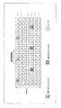
OFDMは、様々な通信システムに適用されている。その一例として、後記非特許文献1では、OFDMを用いたセルラーシステムが検討されている。この非特許文献1のシステムでは、下りリンクに関して、チャネル推定等に用いられる送受間で既知の信号であるパイロット信号(当該非特許文献1中ではreference symbol(RS)と呼ばれている)を、例えば図11に示すような時間及び周波数の2次元配置で送信することが記述されている(非特許文献1のセクション7.1.1.2.2参照)。(1) OFDM system and transmission format (pilot signal)
OFDM is applied to various communication systems. As an example thereof, Non-Patent
即ち、この図11に示す例では、1サブフレーム(=0.5ms=7シンボル時間)の中で、第1のパイロット信号(1streference symbol)R1が、サブフレーム先頭のシンボルに7サブキャリア周期で配置(マッピング)され、第2のパイロット信号(2nd reference symbol)R2が、サブフレームの第5シンボルに7サブキャリア周期で配置(ただし、第1のパイロット信号R1とは異なるサブキャリアに配置)されている。なお、その他のシンボルには各種データ(D)が配置される。In other words, in the example shown in FIG. 11, in one subframe (= 0.5 ms = 7 symbol time), the first pilot signal (1streference symbol) R1 is set to 7 subcarrier periods in the first symbol of the subframe. The second pilot signal (2nd reference symbol) R2 is arranged in the fifth symbol of the subframe with 7 subcarrier periods (however, in a subcarrier different from thefirst pilot signal R1). Arrangement). In addition, various data (D) is arrange | positioned at another symbol.
(2)干渉雑音電力の推定
後記非特許文献2の(13)式(p1560参照)に、干渉雑音電力を推定する式が示されている。この方法は、同一シンボル時間(同一受信時刻)の周波数領域における各パイロット信号の位置でのチャネル推定値を用いる方法で、ある位置でのチャネル推定値Aと、それに対して周波数方向で両隣に位置するパイロット信号のチャネル推定値の平均値Bとを計算し、それらの差分(A−B)の平均電力を基に干渉雑音電力を推定する方法である。(2) Estimation of interference noise power Expression (13) (see p1560) of
(3)干渉雑音電力推定値の利用
ここで、干渉雑音電力推定値は、受信機において様々な目的で用いられる。
例えば、後記非特許文献2には、干渉雑音電力推定値を用いた受信処理の一例が示されており、MIMO復調処理の一部に干渉雑音電力推定値を用いることが記述されている。
また、後記特許文献1の段落0058には、複数ブランチの最大比合成係数として、フェージング係数/雑音電力が公知であることが示されており、雑音電力推定値を受信処理に用いることが記述されている。(3) Use of interference noise power estimation value Here, the interference noise power estimation value is used for various purposes in the receiver.
For example, Non-Patent
Further, paragraph 0058 of
このように、様々な通信システムや受信機において干渉雑音電力が利用されており、そのため干渉雑音電力を精度良く推定することは、非常に重要であり、正しく推定できない場合には、受信機の受信(復調処理)性能劣化につながる。
上述した非特許文献2の技術によれば、遅延分散が小さい場合には、干渉雑音電力を精度良く推定可能であるが、遅延分散が大きくなると、周波数選択性フェージングによる周波数領域でのチャネル変動の一部が雑音として計算されてしまうことにより、高いSNR(Signal to Noise Ratio)領域で正しい推定値を算出することができなくなる(飽和してしまう)という課題がある。 According to the technique of Non-Patent
また、非特許文献2の技術を時間領域について適用して計算する、即ち、ある時刻での基準パイロット信号のチャネル推定値と、それに対して時間方向で両隣に位置するパイロット信号のチャネル推定値の平均値とをそれぞれ計算し、それらの差分の平均電力を求めることにより、干渉雑音電力を推定することも考えられるが、時間選択性フェージングによる時間領域でのチャネル変動などが存在する場合に、同様の課題がある。 Further, the calculation of the technique of Non-Patent
したがって、高速な伝送速度での通信を行なう場合など、非常に高いSNR領域での正確な干渉雑音電力の推定が求められる場合に、受信性能が劣化していた。
本発明は、このような課題に鑑み創案されたもので、周波数領域及び時間領域でのチャネル変動があっても干渉雑音を精度良く推定できるようにすることを目的とする。Therefore, the reception performance has deteriorated when accurate estimation of interference noise power in a very high SNR region is required, such as when performing communication at a high transmission rate.
The present invention has been made in view of such a problem, and an object of the present invention is to make it possible to accurately estimate interference noise even when there is channel fluctuation in the frequency domain and the time domain.
上記の課題を解決するために、本発明では、下記のマルチキャリア通信システムにおける干渉雑音推定方法及び受信処理方法並びに干渉雑音推定装置及び受信機を用いることを特徴としている。即ち、
(1)本発明のマルチキャリア通信システムにおける干渉雑音推定方法は、所定の送信周波数帯域においてパイロット信号が異なる複数の周波数に配置されて周期的に送信されるシステムにおいて、異なる時刻に異なる周波数で受信されたパイロット信号間の平均値を求めるパイロット平均化過程と、前記パイロット平均化過程により得られた各平均値の差分に基づいて干渉雑音を推定する干渉雑音推定過程とを有することを特徴としている。In order to solve the above problems, the present invention is characterized by using an interference noise estimation method, a reception processing method, an interference noise estimation device, and a receiver in the following multicarrier communication system. That is,
(1) An interference noise estimation method in a multicarrier communication system according to the present invention receives pilot signals at different frequencies at different times in a system in which pilot signals are periodically transmitted by being arranged at different frequencies in a predetermined transmission frequency band. A pilot averaging process for obtaining an average value between the pilot signals, and an interference noise estimation process for estimating interference noise based on a difference between the average values obtained by the pilot averaging process. .
(2)ここで、前記パイロット平均化過程では、時間及び周波数の2次元領域において、4つのパイロット信号の配置位置がなす四角形の2つの対角線の両端に位置するパイロット信号間の平均値を計算するのが好ましい。
(3)また、本発明のマルチキャリア通信システムにおける受信処理方法は、所定の送信周波数帯域においてパイロット信号が異なる複数の周波数に配置されて周期的に送信されるシステムにおいて、異なる時刻に異なる周波数で受信されたパイロット信号間の平均値を求めるパイロット平均化過程と、前記パイロット平均化過程により得られた各平均値の差分に基づいて干渉雑音を推定する干渉雑音推定過程と、前記干渉雑音推定過程による推定結果に基づいてマルチキャリア復調処理を行なう復調処理過程とを有することを特徴としている。(2) Here, in the pilot averaging process, an average value between pilot signals located at both ends of two diagonal lines of a quadrangle formed by arrangement positions of four pilot signals is calculated in a two-dimensional region of time and frequency. Is preferred.
(3) Further, the reception processing method in the multicarrier communication system of the present invention is a system in which pilot signals are periodically transmitted by being arranged at a plurality of different frequencies in a predetermined transmission frequency band at different frequencies. A pilot averaging process for obtaining an average value between received pilot signals, an interference noise estimation process for estimating interference noise based on a difference between the average values obtained by the pilot averaging process, and the interference noise estimation process And a demodulating process for performing a multicarrier demodulating process based on the estimation result according to.
(4)さらに、本発明のマルチキャリア通信システムにおける干渉雑音推定装置は、所定の送信周波数帯域においてパイロット信号が異なる複数の周波数に配置されて周期的に送信されるマルチキャリア通信システムにおける干渉雑音推定装置であって、異なる時刻に異なる周波数で受信されたパイロット信号間の平均値を求めるパイロット平均化手段と、前記パイロット平均化手段により得られた各平均値の差分に基づいて干渉雑音を推定する干渉雑音推定手段とをそなえたことを特徴としている。 (4) Furthermore, the interference noise estimation apparatus in the multicarrier communication system of the present invention estimates interference noise in a multicarrier communication system in which pilot signals are arranged at a plurality of different frequencies and transmitted periodically in a predetermined transmission frequency band. An apparatus for estimating an average value between pilot signals received at different frequencies at different times, and estimating interference noise based on a difference between the average values obtained by the pilot averaging means It is characterized by having interference noise estimation means.
(5)また、本発明のマルチキャリア通信システムにおける受信機は、所定の送信周波数帯域においてパイロット信号が異なる複数の周波数に配置されて周期的に送信されるマルチキャリア通信システムにおける受信機であって、異なる時刻に異なる周波数で受信されたパイロット信号間の平均値を求めるパイロット平均化手段と、前記パイロット平均化手段により得られた各平均値の差分に基づいて干渉雑音を推定する干渉雑音推定手段とを有する干渉雑音推定装置と、前記干渉雑音推定装置による推定結果に基づいてマルチキャリア復調処理を行なう復調処理手段とをそなえたことを特徴としている。 (5) A receiver in the multicarrier communication system of the present invention is a receiver in a multicarrier communication system in which pilot signals are periodically transmitted by being arranged at a plurality of different frequencies in a predetermined transmission frequency band. Pilot averaging means for obtaining an average value between pilot signals received at different frequencies at different times, and interference noise estimating means for estimating interference noise based on the difference between the average values obtained by the pilot averaging means And a demodulation processing means for performing a multicarrier demodulation process based on the estimation result by the interference noise estimation device.
上記本発明によれば、少なくとも次のような効果ないし利点が得られる。
即ち、周波数方向あるいは時間方向のチャネル変動が大きくても、異なる時刻に異なる周波数で受信されたパイロット信号間の平均を求めることで、チャネル変動による平均値の変動が吸収されるため、周波数方向あるいは時間方向のチャネル変動が干渉雑音の推定計算に影響することを抑制することができ、精度良く干渉雑音を推定することができ、結果として、受信性能(復調能力)の向上を図ることができる。According to the present invention, at least the following effects or advantages can be obtained.
That is, even if the channel fluctuation in the frequency direction or the time direction is large, the average value fluctuation due to the channel fluctuation is absorbed by calculating the average between pilot signals received at different frequencies at different times. It is possible to suppress the influence of the channel fluctuation in the time direction on the estimation calculation of the interference noise, the interference noise can be estimated with high accuracy, and as a result, the reception performance (demodulation capability) can be improved.
11 サブキャリアマッピング部
12 IFFT
13 DA変換器
14 アップコンバージョン部
15 送信アンテナ
21 受信アンテナ
22 ダウンコンバージョン部
23 AD変換器
24 FFT
25 チャネル推定部(パイロット抽出部)
26 干渉雑音電力推定部
261(261a,261b) パイロット平均化手段(過程)
262 干渉雑音推定手段(過程)
263 差分検出手段(過程)
264 電力化手段(過程)
265 平均化手段(過程)
27 復調処理部
28 推定制御部(判断手段、制御手段)11
13
25 Channel estimation unit (pilot extraction unit)
26 Interference noise power estimation unit 261 (261a, 261b) Pilot averaging means (process)
262 Interference noise estimation means (process)
263 Difference detection means (process)
H.264 Electrification means (process)
265 Averaging means (process)
27
以下、図面を参照して、本発明の実施の形態について説明する。ただし、本発明は、以下に説明する実施形態に限定されず、本発明の趣旨を逸脱しない範囲で種々変形して実施できることはいうまでもない。
〔A〕一実施形態の説明
(A1)OFDMフォーマットの説明
本実施形態では、OFDM方式を採用したシステムを前提とする。Embodiments of the present invention will be described below with reference to the drawings. However, it goes without saying that the present invention is not limited to the embodiments described below, and can be variously modified and implemented without departing from the spirit of the present invention.
[A] Description of Embodiment (A1) Description of OFDM Format This embodiment is premised on a system that employs the OFDM scheme.
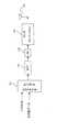
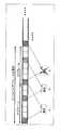
即ち、OFDM送信機は、例えば図1に示すように、シンボル時間毎にN個(Nは2以上の整数で、例えば、N=512等)の入力信号を各N個のサブキャリア(周波数)で送信することを前提とする。つまり、N個のサブキャリア×時間の周波数リソースが存在する。そして、この図1に示す周波数×時間のリソースにおけるそれぞれの升目(シンボル)には、異なる送信データを配置(マッピング)することが可能である。なお、本例では、前記非特許文献1の記述にならって、7シンボル時間(0.5ms)×N個のサブキャリアで1サブレームを構成するものとする。 That is, for example, as shown in FIG. 1, the OFDM transmitter receives N input signals for each symbol time (N is an integer of 2 or more, for example, N = 512, etc.) for each of N subcarriers (frequency). It is assumed that the data will be transmitted. That is, there are N subcarriers × time frequency resources. Then, different transmission data can be arranged (mapped) in each cell (symbol) in the frequency × time resource shown in FIG. In this example, according to the description in
また、パイロット信号の配置として、図2に示す配置を例として用いる。即ち、サブフレームの先頭シンボルで、M(=6)サブキャリア間隔(周期)でパイロット信号を配置する。パイロット信号は、送受間で何らかの既知の信号パターンであり、以下の説明において、サブフレーム#n(n=0〜N−1),サブキャリア#k(k=0〜N−1)の位置に配置された送信パイロット信号パターンをx(n,k)と表記することとする。また、パイロット信号が配置(マッピング)されたサブキャリア(周波数)をパイロットチャネルと呼び、そのチャネル推定値をパイロットチャネル値あるいは単にチャネル値と呼ぶことがある。 Further, as an arrangement of pilot signals, the arrangement shown in FIG. 2 is used as an example. That is, pilot signals are arranged at M (= 6) subcarrier intervals (periods) at the head symbol of the subframe. The pilot signal is a known signal pattern between transmission and reception, and in the following description, at a position of subframe #n (n = 0 to N−1) and subcarrier #k (k = 0 to N−1). The arranged transmission pilot signal pattern is expressed as x (n, k). Further, a subcarrier (frequency) on which a pilot signal is arranged (mapped) may be referred to as a pilot channel, and the channel estimation value may be referred to as a pilot channel value or simply a channel value.
そして、この図2に示すように、上記のパイロット信号がサブフレーム周期で繰り返し同じサブキャリアに配置されてOFDM送信機から送信されるものとする。なお、以下では、説明の簡略化のため、パイロット信号は、全て1+0jとして送信されるものとする。
(A2)OFDM送信機の説明
上記のサブフレーム構成で、各シンボルにおいて各サブキャリアに各信号をマッピングして送信するOFDM送信機の構成例を図3に示す。この図3に示すように、OFDM送信機(以下、単に「送信機」という)は、その要部に着目すると、例えば、サブキャリアマッピング部11、IFFT(Inverse Fast Fourier Transformer)12、DA(Digitalto Analog)変換器13、アップコンバージョン部14及び送信アンテナ15をそなえて構成されている。Then, as shown in FIG. 2, it is assumed that the above pilot signal is repeatedly arranged in the same subcarrier in the subframe period and transmitted from the OFDM transmitter. In the following, for simplification of description, it is assumed that all pilot signals are transmitted as 1 + 0j.
(A2) Description of OFDM Transmitter FIG. 3 shows a configuration example of an OFDM transmitter that maps and transmits each signal to each subcarrier in each symbol in the above subframe configuration. As shown in FIG. 3, an OFDM transmitter (hereinafter simply referred to as “transmitter”) is focused on its main parts, for example, a
ここで、サブキャリアマッピング部11は、パイロット信号及びその他のデータ信号を入力信号として受けて、図1及び図2により上述した時間×周波数の2次元のシンボル配置となるように、シンボル時間毎にN個の入力信号をN個のサブキャリアにマッピングするものである。
IFFT12は、サブキャリアマッピング部11によりサブキャリアマッピングされた周波数領域の信号をIFFT処理することにより時間領域の信号に変換するものであり、DA変換器13は、当該時間領域の信号をアナログ信号に変換するものであり、アップコンバージョン部14は、このDA変換器13からのアナログ信号を送信無線周波数(RF)の信号に周波数変換(アップコンバート)するものであり、送信アンテナ15は、当該送信RF信号を受信機に向けて空間へ放射するものである。Here, the
The
かかる構成により、本例の送信機では、送信すべきパイロット信号及びその他のデータ信号が、サブキャリアマッピング部11にて、図1及び図2に示した2次元シンボル配置となるように、シンボル時間毎にN個のサブキャリアにマッピングされ、IFFT12にて、IFFT処理されて時間領域の信号に変換され、DA変換器13にて、アナログ信号に変換された後、アップコンバージョン部14にて、送信RF信号にアップコンバートされて、送信アンテナ15から受信機に向けて送信される。 With this configuration, in the transmitter of this example, the pilot signal and other data signals to be transmitted are symbol times so that the
(A3)OFDM受信機の説明
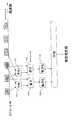
次に、上述した送信機から送信されたRF信号を受信するOFDM受信機の構成例を図4に示す。この図4に示すように、本実施形態のOFDM受信機(以下、単に「受信機」という)は、その要部に着目すると、例えば、受信アンテナ21、ダウンコンバージョン部22、AD(Analog to Digital)変換器23、FFT24、パイロット抽出部25、干渉雑音電力推定部26及び復調処理部27をそなえて構成されている。ただし、この図4では、受信アンテナ21、ダウンコンバージョン部22、AD変換器23、FFT24、パイロット抽出部25及び干渉雑音電力推定部26をそれぞれ複数(2系統)そなえた受信ダイバーシティ(あるいはMIMO受信)構成を示している。(A3) Description of OFDM Receiver Next, FIG. 4 shows a configuration example of an OFDM receiver that receives an RF signal transmitted from the transmitter described above. As shown in FIG. 4, the OFDM receiver of the present embodiment (hereinafter simply referred to as “receiver”) focuses on its main parts, for example, a receiving
ここで、受信アンテナ21は、前記送信機から送信されたRF信号を受信するものであり、ダウンコンバージョン部22は、この受信アンテナ21で受信されたRF信号をベースバンド周波数にまで周波数変換(ダウンコンバート)するものであり、AD変換器23は、このダウンコンバージョン部22により得られた受信ベースバンド信号をディジタル信号に変換するものである。 Here, the receiving
FFT24は、AD変換器23からのディジタル信号を、各シンボルタイミングにおいてNサンプル毎にFFT処理することにより、時間領域の信号から周波数領域の信号に変換してN個のサブキャリア信号を抽出するものであり、チャネル推定部(パイロット抽出部)25は、例えば受信パイロット信号とパイロット信号のレプリカとの相関演算により、当該N個のサブキャリア信号から、既述のように周波数×時間領域に配置されたパイロット信号を抽出して伝播路歪みを推定し(つまり、チャネル推定値を求め)、送信機で用いたパイロットパターンをキャンセルするものである。 The
干渉雑音電力推定部26は、上記パイロット抽出部25により抽出されたパイロット信号に基づいて干渉雑音(電力)を推定するもので、本例では、図6及び図7(A)により後述するように、周波数軸上で隣接する2つのパイロット、および、時間軸上で隣接する2つのパイロットの合計4つのパイロット信号の配置が作る四角形の対角線に注目し、それぞれの対角線の両端に位置するパイロット信号のチャネル推定値の平均値を計算し、2つの対角線に対応する2つの平均値の差分の電力平均により干渉雑音電力を推定するようになっている。 The interference noise
復調処理部27は、パイロット抽出部25により抽出されたパイロット信号および干渉雑音電力推定部26により得られた干渉雑音電力の推定値を用いて、同期検波や複数受信アンテナ21での受信信号の合成等の復調処理を行なうものである。
以下、上述のごとく構成された本例の受信機の動作について説明すると、受信アンテナ21で受信されたRF信号は、ダウンコンバージョン部22にて、ベースバンド周波数にまでダウンコンバートされた後、AD変換器23にてディジタル信号にAD変換される。次いで、このAD変換後信号は、FFT24にて、各シンボルタイミングにおいてNサンプル毎にFFT処理されることにより、時間領域の信号から周波数領域の信号に変換されてN個のサブキャリア信号が抽出され、復調処理部27とパイロット抽出部25とにそれぞれ入力される。The
Hereinafter, the operation of the receiver of the present example configured as described above will be described. The RF signal received by the receiving
パイロット抽出部25では、上記FFT処理後の受信信号から既述のように周波数×時間領域に配置されたパイロット信号を抽出し、送信時に用いたパイロットパターンをキャンセルする。
例えば、サブフレーム#n,サブキャリア#kの位置に配置された送信パイロット信号パターンをx(n,k)と表す場合に、受信アンテナ#aで対応するシンボルでの対応するサブキャリア#kでの受信信号r(a,n,k)は、下記(1)式で表すことができる。The
For example, when the transmission pilot signal pattern arranged at the position of subframe #n and subcarrier #k is represented as x (n, k), it is the corresponding subcarrier #k in the symbol corresponding to reception antenna #a. The received signal r (a, n, k) can be expressed by the following equation (1).

ただし、この(1)式において、Hは伝播路による振幅及び位相の変化を複素数で表現したものであり、zは伝播路で付加される干渉雑音を表している。
そして、パイロット抽出部25は、干渉雑音電力推定部26及び復調処理部27に出力する信号を、下記の(2)式で表されるパターンキャンセルした信号とするのである。However, in this equation (1), H represents a change in amplitude and phase due to the propagation path as a complex number, and z represents interference noise added in the propagation path.
And the
復調処理部27では、パイロット抽出部25により抽出されたパイロット信号および干渉雑音電力推定部26により得られた干渉雑音電力の推定値を用いて同期検波や複数受信アンテナ21での受信信号の合成などの復調処理を行なうが、例えば、以下のように復調処理を行なうことができる。
即ち、受信アンテナ#a,サブフレーム#n,サブフレーム内のシンボル番号#lにおいて、サブキャリア#kで送信された信号をd(a,n,l,k)と表現する場合に、受信信号は、下記の(3)式で表されるから、2つの受信アンテナ21の受信信号のダイバーシティ合成は、干渉雑音電力推定部26から入力される推定値σ2est(a,n)を用いて、下記の(4)式として処理することができる。
。In the
That is, when a signal transmitted on subcarrier #k is expressed as d (a, n, l, k) in reception antenna #a, subframe #n, and symbol number #l in the subframe, the received signal Is expressed by the following equation (3), the diversity combining of the received signals of the two receiving
.
ただし、(4)式において、[k/M]は、k/Mを四捨五入した結果を表す。
次に、本例の要部である干渉雑音電力推定部26による推定方法を説明する。
ただし、従来技術との比較で説明するために、まず、前記非特許文献2の推定方法を本例のシステムに適用する場合の、干渉雑音電力の推定方法を示す。
非特許文献2の推定方法(以下、単に従来方法と称する)では、受信アンテナ#a,サブフレーム#nでのパイロット信号h(a,n,Mi)を用いて推定する。その推定方法は、K回の平均化で推定する場合、下記の(5)式で表すことができる。However, in the equation (4), [k / M] represents the result of rounding off k / M.
Next, an estimation method by the interference noise
However, in order to explain in comparison with the prior art, first, an interference noise power estimation method when the estimation method of
In the estimation method of Non-Patent Document 2 (hereinafter simply referred to as the conventional method), estimation is performed using pilot signals h (a, n, Mi) at reception antenna #a and subframe #n. The estimation method can be expressed by the following equation (5) when estimation is performed by averaging K times.
これを図示化すると、例えば図5に示すようになる。即ち、従来方法では、アンテナ#a,サブフレーム#nでのパイロット信号h(a,n,Mi)を基準(中心)として周波数軸上で両隣に位置する2つのパイロット信号h(a,n,M(i−1))及びh(a,n,M(i+1))の合計3つの同一シンボル時間のパイロット信号を用いる。ただし、図5では、i=1の場合で、受信アンテナ番号(a),サブフレーム番号(n)の変数表記は省略し、基準パイロット信号をh(M)、周波数軸上その両隣に位置する2つのパイロット信号をh(0)及びh(2M)と表記してある。 This is illustrated in FIG. 5, for example. In other words, in the conventional method, two pilot signals h (a, n, n) located on both sides on the frequency axis with the pilot signal h (a, n, Mi) at antenna #a and subframe #n as a reference (center). A total of three pilot signals having the same symbol time of M (i−1)) and h (a, n, M (i + 1)) are used. However, in FIG. 5, in the case of i = 1, the variable notation of the receiving antenna number (a) and the subframe number (n) is omitted, and the reference pilot signal is h (M), which is located on both sides of the frequency axis. The two pilot signals are denoted as h (0) and h (2M).
より詳細には、基準パイロット信号h(M)の周波数軸上両隣に位置する2つのパイロット信号h(M(i−1))及びh(M(i+1))の平均値を求め、その平均値と基準パイロット信号h(M)との差分を電力化することを、同一サブフレーム#nの同一シンボル時間(例えば先頭シンボル)に配置されている全パイロット信号について行ない、それらの電力平均値の定数倍を干渉雑音電力の推定値として求めるのである。 More specifically, an average value of two pilot signals h (M (i−1)) and h (M (i + 1)) located on both sides on the frequency axis of the reference pilot signal h (M) is obtained, and the average value is obtained. The difference between the reference pilot signal h (M) and the reference pilot signal h (M) is converted into electric power for all pilot signals arranged in the same symbol time (for example, the first symbol) of the same subframe #n, and the constant of the average power value Double is obtained as an estimate of the interference noise power.
これは、例えば図7(B)に模式的に示すように、実線矢印34で示される両端の2つのパイロット信号のチャネル値の平均値と、当該矢印34の中央に位置する基準パイロット信号のチャネル値との差分を基に干渉雑音電力を推定していることを意味する。
これに対し、本例の干渉雑音電力推定部26による推定方法は、受信アンテナ#a,時間的に異なる2つのサブフレーム#n,#n+1でのパイロット信号(4つ)を用いて推定する。その推定方法は、K回の平均化で推定する場合、下記の(6)式で表すことができる。For example, as schematically shown in FIG. 7B, the average value of the channel values of the two pilot signals at both ends indicated by the
On the other hand, the estimation method by the interference noise
これを図示化すると、例えば図6に示すようになる。即ち、本例の推定方法では、同一受信アンテナ#aについて、
(1)或るサブフレーム#nの或るサブキャリア#Miに配置されているパイロット信号
h(a,n,Mi)と、次のサブフレーム#n+1において当該パイロット信号h(a,n,Mi)に対して周波数軸方向(高周波数側)に隣接配置されているパイロット信号h(a,n+1,M(i+1))(サブキャリア番号は#M(i+1))との平均値を求める(パイロット平均化過程:符号261(261a)参照)とともに、
(2)前記サブフレーム#nにおいて前記パイロット信号h(a,n,Mi)に対して周
波数軸方向(高周波数側)に隣接配置されているパイロット信号h(a,n,M(i+1))(サブキャリア番号は#M(i+1))と、次のサブフレーム#n+1において当該パイロット信号h(a,n,M(i+1))に対して周波数方向(低周波数側)に隣接配置されているパイロット信号h(a,n+1,Mi)(サブキャリア番号は#Mi)との平均値を求め(パイロット平均化過程:符号261(261b)参照)、
(3)それらの平均値の差分を差分検出手段(過程)263にて検出し電力化手段(過程)264にて電力化することを、同一シンボル時間(例えば先頭シンボル)に配置されている全パイロット信号について行ない、それらの電力平均値を平均化手段(過程)265により干渉雑音電力の推定値として求める(干渉雑音電力推定過程)のである。This is illustrated in FIG. 6, for example. That is, in the estimation method of this example, for the same receiving antenna #a,
(1) A pilot signal h (a, n, Mi) arranged in a certain subcarrier #Mi of a certain subframe #n and the pilot signal h (a, n, Mi) in the next subframe # n + 1 ) For the pilot signal h (a, n + 1, M (i + 1)) (subcarrier number is #M (i + 1)) arranged adjacent to the frequency axis direction (high frequency side) (pilot) Along with the averaging process: reference numeral 261 (261a))
(2) Pilot signal h (a, n, M (i + 1)) arranged adjacent to the pilot signal h (a, n, Mi) in the frequency axis direction (high frequency side) in the subframe #n (Subcarrier number is #M (i + 1)) and adjacent to the pilot signal h (a, n, M (i + 1)) in the next subframe # n + 1 in the frequency direction (low frequency side) An average value of the pilot signal h (a, n + 1, Mi) (subcarrier number is #Mi) is obtained (pilot averaging process: see reference numeral 261 (261b)),
(3) The difference between these average values is detected by the difference detecting means (process) 263 and the power generation means (process) 264 is converted into electric power so that all the symbols arranged in the same symbol time (for example, the first symbol) are arranged. This is performed on the pilot signal, and the average power of those is obtained as an estimated value of the interference noise power by the averaging means (process) 265 (interference noise power estimation process).
これは、例えば図7(A)に模式的に示すように、実線矢印32の両端の2つのパイロット信号のチャネル値の平均値と、点線矢印33の両端の2つのパイロット信号のチャネル推定値の平均値との差分を基に干渉雑音電力を推定していることを意味する。
換言すれば、本例の干渉雑音電力推定部26は、異なる時刻に異なるサブキャリア(周波数)で受信されたパイロット信号(パイロットチャネル値)間の平均値を求めるパイロット平均化手段(過程)261(261a,261b)と、このパイロット平均化手段261(261a,261b)により得られた各平均値の差分に基づいて干渉雑音を推定する干渉雑音推定手段(過程)262〔差分検出手段(過程)263,電力化手段(過程)264及び平均化手段(過程)265〕とを具備していることになる。For example, as schematically shown in FIG. 7A, the average value of the channel values of the two pilot signals at both ends of the
In other words, the interference noise
そして、パイロット平均化手段(過程)261(261a,261b)にて、周波数方向に隣接する2つのパイロット信号、および、時間方向に隣接する2つのパイロット信号の合計4つのパイロット信号の配置が作る四角形の対角線(前記矢印32,33参照)に注目し、それぞれの対角線32,33の両端のパイロット信号のチャネル値の平均値を計算し、干渉雑音推定手段(過程)262(263〜265)にて、2つの対角線32,33に対応する2つの平均値の差分の電力平均により干渉雑音電力を推定しているのである。 Then, the pilot averaging means (process) 261 (261a, 261b) is a quadrangle formed by the arrangement of a total of four pilot signals of two pilot signals adjacent in the frequency direction and two pilot signals adjacent in the time direction. In particular, the average value of the pilot signal channel values at both ends of each of the
以下、本実施形態の推定方法による得られる効果を従来方法と比較して説明する。一例として、時間選択性フェージングが無く、周波数選択性フェージングが大きい場合(つまり、例えば図2に示す周波数方向の隣接パイロット信号のチャネル推定値が大きく変動する場合)を考える。
従来方法においては、例えば図8に模式的に示すように、遅延分散の大きい伝播環境である場合に、大きな周波数選択性フェージング(実線曲線30参照)が発生し、実線矢印34の両端2つのパイロット信号(○印参照)間でチャネル変動が見えており、中央のパイロット信号位置(●印参照)でのチャネル値と差分を取ると、干渉雑音が無い伝播環境であっても、本来計算されるべき干渉雑音電力値からずれることになる。Hereinafter, the effect obtained by the estimation method of the present embodiment will be described in comparison with the conventional method. As an example, let us consider a case where there is no time selective fading and frequency selective fading is large (that is, for example, when the channel estimation value of the adjacent pilot signal in the frequency direction shown in FIG. 2 fluctuates greatly).
In the conventional method, as schematically shown in FIG. 8, for example, in a propagation environment with a large delay dispersion, a large frequency selective fading (see the solid curve 30) occurs, and two pilots at both ends of the
即ち、図8の場合では、周波数選択性フェージングが小さい場合(点線曲線31参照)には、○印で示す周波数方向に隣接するパイロットチャネル値の平均値は、●印で示す中央のパイロットチャネル値と一致又は略一致するため、正しい干渉雑音を推定できるが、大きな周波数選択性フェージングのある場合に、○印で示す周波数方向に隣接するパイロットチャネル値の平均値は、●印で示す中央のパイロットチャネル値とずれており、このずれを含んで干渉雑音電力が計算されてしまう。このように、実際には干渉雑音が存在しない場合であっても、周波数方向でのチャネル変動が、一部干渉雑音電力として計算されてしまうことにより、干渉雑音電力を本来よりも大きく推定してしまい、正しい干渉雑音電力を推定することができなくなる。 That is, in the case of FIG. 8, when frequency selective fading is small (see dotted curve 31), the average value of pilot channel values adjacent to each other in the frequency direction indicated by ◯ is the center pilot channel value indicated by ●. Therefore, when there is a large frequency selective fading, the average value of the pilot channel values adjacent in the frequency direction indicated by the circle is the center pilot indicated by the circle. There is a deviation from the channel value, and the interference noise power is calculated including this deviation. In this way, even if there is actually no interference noise, the channel fluctuation in the frequency direction is partially calculated as interference noise power, so that the interference noise power is estimated to be larger than the original. As a result, the correct interference noise power cannot be estimated.
これに対し、同様の周波数方向のチャネル変動がある場合の本実施形態の推定方法の概念を図9に示す。この図9に示すように、本例の推定方法では、異なるサブフレーム#n,#n+1(つまり、異なる時刻T(n),T(n+1))での周波数軸方向に隣接する2つのパイロットチャネル値の組(○印及び●印参照)の平均値をそれぞれ算出することになる(実線矢印32及び点線矢印33参照)。ただし、図9では、見やすくするために、実線矢印32と点線矢印33とをずらして記述しているが、本来は重なるものである。 On the other hand, FIG. 9 shows the concept of the estimation method of this embodiment when there is a similar channel fluctuation in the frequency direction. As shown in FIG. 9, in the estimation method of this example, two pilot channels adjacent in the frequency axis direction at different subframes #n and # n + 1 (that is, at different times T (n) and T (n + 1)). The average value of the set of values (see ◯ and ● marks) is calculated (see
これは、時間方向のチャネル変動が小さい、つまり、異なる2つの時刻T(n),T(n+1)でのパイロットチャネル値の変動が小さい場合を例としているため、どんなに周波数方向のチャネル変動が大きくても、或る時刻T(n)で実線矢印32の両端のパイロットチャネル値で計算した平均値(実線矢印32の中点)と、異なる時刻T(n+1)で点線矢印33の両端のパイロットチャネル値で計算した平均値(点線矢印33の中点)とは一致することになる。したがって、周波数選択性フェージングが大きい伝播環境下でも、周波数方向のチャネル変動が干渉雑音電力推定値として計算されることが無くなり、精度良く干渉雑音電力を推定できるのである。 This is an example in which the channel fluctuation in the time direction is small, that is, the fluctuation of the pilot channel value at two different times T (n) and T (n + 1) is small. Therefore, no matter how large the channel fluctuation in the frequency direction is. However, the average value calculated by the pilot channel values at both ends of the
なお、上記とは逆に、周波数選択性フェージングが小さく、時間選択性フェージングが大きい伝播環境下(つまり、例えば図2に示す時間方向のパイロット信号のチャネル値が大きく変動する場合)であっても、本例の推定方法によれば、正しい干渉雑音電力推定を求めることが可能である。即ち、時間方向のチャネル変動が大きくても、周波数方向のチャネル変動は小さいため、異なる時刻T(n),T(n+1)で異なるパイロットチャネル値どうしの平均値の差分をとる限り、時間方向のチャネル変動によるずれ分が吸収(キャンセル)されるため、精度良く干渉雑音電力を推定できることになる。 Contrary to the above, even in a propagation environment where the frequency selective fading is small and the time selective fading is large (that is, for example, when the channel value of the pilot signal in the time direction shown in FIG. 2 fluctuates greatly). According to the estimation method of this example, it is possible to obtain a correct interference noise power estimation. That is, even if the channel fluctuation in the time direction is large, the channel fluctuation in the frequency direction is small. Therefore, as long as the difference between the average values of the different pilot channel values at different times T (n) and T (n + 1) is obtained, Since the shift due to channel fluctuation is absorbed (cancelled), the interference noise power can be estimated with high accuracy.
つまり、本例の推定方法によれば、例えば下記表1に示すように、周波数選択性フェージング及び時間選択性フェージングがともに大きな伝播環境を除いたいずれの伝播環境においても、干渉雑音電力を精度良く推定することが可能である。 In other words, according to the estimation method of this example, as shown in Table 1 below, for example, as shown in Table 1, interference noise power is accurately obtained in any propagation environment except for a propagation environment in which both frequency selective fading and time selective fading are large. It is possible to estimate.
これに対して、従来方法(つまり、周波数方向のパイロットチャネル値のみを用いる方法)や時間方向のパイロットチャネル値のみを用いる方法では、下記表2,表3に示すように、時間方向のチャネル変動が小さくても周波数方向のチャネル変動が大きい場合や、周波数方向のチャネル変動が小さくても時間方向のチャネル変動が大きい場合にも、干渉雑音電力に推定誤差が生じてしまう。 On the other hand, in the conventional method (that is, the method using only the pilot channel value in the frequency direction) and the method using only the pilot channel value in the time direction, as shown in Tables 2 and 3, the channel fluctuation in the time direction is Even when the channel fluctuation in the frequency direction is large even when the frequency fluctuation is small, or when the channel fluctuation in the time direction is large even when the channel fluctuation in the frequency direction is small, an estimation error occurs in the interference noise power.
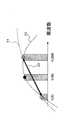
図10に、周波数選択性フェージングおよび時間選択性フェージングによるチャネル変動が存在する場合の従来技術と本例の推定方法による、受信アンテナ1本あたりのSNR(dB)に対するSIR推定結果平均値(dB)をコンピュータシミュレーションした結果の一例を示す。ただし、シミュレーション条件は、前記非特許文献1のシステムにおける、“Typical Urban Channel Model”(ANNEX A.2.1.2(p116-p120)参照)における諸条件と同等としている。 FIG. 10 shows an average value (dB) of SIR estimation results with respect to SNR (dB) per receiving antenna according to the conventional technique and the estimation method of this example when there is channel variation due to frequency selective fading and time selective fading. An example of the result of computer simulation is shown. However, the simulation conditions are the same as the conditions in the “Typical Urban Channel Model” (see ANNEX A.2.1.2 (p116-p120)) in the system of
この図10において、特性40が従来技術によるシミュレーション結果、特性41が本例の推定方法によるシミュレーション結果を示しており、従来技術では受信品質がSNR=10dBを超えた付近から推定誤差が大きくなり始め、SNR=30dBの良好な受信品質環境(つまり、実際には干渉雑音が小さいか無い)場合であっても、SIR推定結果平均値は20dB以下となっており、飽和してしまうが、本例の推定方法によれば、非常に高いSNR値まで測定可能で正確な推定が可能であることが分かる。 In FIG. 10, the characteristic 40 shows the simulation result by the conventional technique, and the characteristic 41 shows the simulation result by the estimation method of this example. In the conventional technique, the estimation error starts to increase from the vicinity where the reception quality exceeds SNR = 10 dB. Even in the case of a good reception quality environment of SNR = 30 dB (that is, actually, the interference noise is small or not), the average value of the SIR estimation result is 20 dB or less and is saturated. According to the estimation method, it is understood that a very high SNR value can be measured and accurate estimation is possible.
以上のように、本実施形態の推定方法によれば、周波数選択性フェージング及び時間選択性フェージングのいずれか一方が大きい伝播環境下においても、干渉雑音電力を精度良く推定することが可能となる。
〔B〕変形例の説明
上述した実施形態においては、図2に示す配置、即ち、サブフレームの先頭シンボルで、M(=6)サブキャリア間隔(周期)でパイロット信号を配置して送信することを前提として、時間方向及び周波数方向にそれぞれ隣接する4つのパイロット信号位置がなす四角形の対角線両端に位置する各2つのパイロット信号のチャネル値の平均を求めているが、本発明はこれに限定されず、他の配置の場合にも、本発明は適用可能であり、上記と同等の作用効果を得ることができる。As described above, according to the estimation method of the present embodiment, it is possible to accurately estimate the interference noise power even in a propagation environment where either one of frequency selective fading and time selective fading is large.
[B] Description of Modifications In the above-described embodiment, pilot signals are arranged and transmitted at M (= 6) subcarrier intervals (periods) in the arrangement shown in FIG. As a premise, the average of channel values of two pilot signals located at both ends of a rectangular diagonal line formed by four pilot signal positions adjacent in the time direction and the frequency direction is obtained, but the present invention is not limited to this. Of course, the present invention can also be applied to other arrangements, and the same effects as those described above can be obtained.
例えば、パイロット信号の配置されるサブキャリア間隔がシンボル時間毎に異なる場合や、同一サブフレーム内の複数のシンボル時間でパイロット信号が所定サブキャリア間隔で配置される場合であっても、時間方向及び周波数方向にそれぞれ隣接する4つのパイロット信号位置が形成する四角形の対角線両端に位置する各2つのパイロット信号のチャネル値の平均を求めることにより、少なくとも従来技術に比してSIRを精度良く推定することが可能となる。 For example, even when the subcarrier interval in which the pilot signal is arranged is different for each symbol time or when the pilot signal is arranged at a predetermined subcarrier interval in a plurality of symbol times in the same subframe, By estimating the average of channel values of two pilot signals located at both ends of a square diagonal line formed by four pilot signal positions adjacent to each other in the frequency direction, at least SIR can be estimated more accurately than in the prior art. Is possible.
また、平均化対象とするパイロット信号位置は、周波数方向及び時間方向のいずれについても、必ずしも隣接パイロット信号位置でなくてもよい。もっとも、周波数方向及び時間方向のいずれについても、距離の近いパイロット信号位置でのパイロットチャネル値を用いるほど、推定精度は向上する。
以下に、幾つかの変形例について説明する。なお、以下の変形例の説明において、既述の符号と同一符号を付して説明する部分は、特に断らない限り、既述の部分と同一若しくは同様の部分を示す。Also, the pilot signal positions to be averaged are not necessarily adjacent pilot signal positions in both the frequency direction and the time direction. However, in both the frequency direction and the time direction, the estimation accuracy improves as the pilot channel values at the pilot signal positions closer to each other are used.
Hereinafter, some modified examples will be described. Note that, in the following description of the modified examples, parts described with the same reference numerals as those described above indicate the same or similar parts as those described above unless otherwise specified.
(B1)第1変形例
前述した実施形態では、時間的に隣接する2つのサブフレーム#n,#n+1でのパイロット信号(図2の斜線部で示すシンボルであって図11における第1のパイロット信号R1に相当する)を用いる場合として説明したが、図11に示したパイロット配置の場合、即ち、第1のパイロット信号R1と第2のパイロット信号R2とが、同一サブフレーム内の複数シンボル時間で異なるサブキャリア周波数に所定サブキャリア間隔で配置される場合には、同様の推定方法を第2のパイロット信号R2にも適用することが可能である。(B1) First Modification In the above-described embodiment, pilot signals (symbols indicated by hatching in FIG. 2 and the first pilot in FIG. 11) in two temporally adjacent subframes #n and # n + 1. has been described as the case of using the equivalent to a signal R1), when the pilot arrangement shown in FIG. 11, i.e., a first pilot signal R1 and the second pilot signal R2 and are in the same sub-frame when placed at predetermined subcarrier intervals in the sub-carrier frequencies different in more symbol times, it is possible to apply the same estimation method in the second pilot signal R2.
この場合には、第1のパイロット信号R1についての推定方法を第2のパイロット信号R2にも適用し、それらを平均化することにより、より精度の高い干渉雑音電力の推定が可能となる。
より詳細には、アンテナ#a,サブフレーム#nのそれぞれ帯域端からi番目にマッピングされた第1のパイロット信号R1をh(1,a,n,Mi)、第2のパイロット信号R2をh(2,a,n,Mi)とそれぞれ表現する場合、これらのパイロットシンボルR1及びR2をそれぞれパイロット抽出部25(図4参照)において抽出し、パイロットシンボルパターンをキャンセルした信号とする。In this case, it is possible to estimate the interference noise power with higher accuracy by applying the estimation method for thefirst pilot signal R1 to the second pilot signal R2 and averaging them. .
More specifically, the first pilot signal R1 mapped i-th from the band edge of each of the antenna #a and the subframe #n is represented by h (1, a, n, Mi) and the second pilot signal R2. Is expressed as h (2, a, n, Mi), respectively, these pilot symbols R1 and R2 are extracted by the pilot extraction unit 25 (see FIG. 4), and the pilot symbol pattern is canceled. .
そして、パイロットシンボルR1に関してK1回、パイロットシンボルR2に関してK2回の平均化でそれぞれ推定する場合、それぞれ推定される干渉雑音電力(雑音推定値)σ2est(1,a,n),σ2est(2,a,n)は、下記の(7)式,(8)式で表すことができる。なお、K1とK2とは同じ回数でも異なる回数でもよい。Then, K1 times with respect to the pilot symbols R1, when estimating each intwo averaging K with respect to the pilot symbols R2, interference noise power estimated respectively (noiseestimate) σ 2 est (1, a , n) , Σ2est (2, a, n) can be expressed by the following equations (7) and (8). Note that K1 and K2 may be the same number or different numbers.
これらの(7)式,(8)式を図示化すると、それぞれ、図6と同様になる。
これらの(7)式,(8)式により得られた各雑音推定値σ2est(1,a,n),σ2est(2,a,n)を、下記の(9)式の平均化することにより、精度の改善された推定値σ2est(a,n)を得ることができる。These equations (7) and (8) are illustrated in the same manner as in FIG.
The noise estimated values σ2est (1, a, n) and σ2est (2, a, n) obtained by these equations (7) and (8) are averaged by the following equation (9). Thus, it is possible to obtain an estimated value σ2est (a, n) with improved accuracy.
(B2)第2変形例
第2変形例の推定方法として、例えば図12に示すように、点線矢印51の両端に配置されたパイロットシンボルR1、即ち、異なるサブフレーム(異なるシンボル時間)で同じサブキャリア周波数に配置されたパイロットシンボルR1どうしの平均値(時間方向平均値)と、実線矢印52の両端に配置されたパイロットシンボルR2、即ち、同じサブフレーム内の同じシンボル時間で異なるサブキャリア周波数に配置されたパイロットシンボルR2どうしの平均値(周波数方向平均値)との差分を用いる方法が考えられる。(B2) Second Modification As an estimation method of the second modification, for example, as shown in FIG. 12, pilot symbols R1 arranged at both ends of a dotted
この場合には、2つのパイロットシンボルR1及び2つのパイロットシンボルR2を用いて、図6により説明した推定方法を適用することにより、より精度の高い干渉雑音電力の推定が可能となる。
即ち、アンテナ#a,サブフレーム#nのそれぞれ帯域端からi番目にマッピングされた第1のパイロットシンボルR1をh(1,a,n,Mi)、第2のパイロットシンボルR2をh(2,a,n,Mi)とそれぞれ表現した場合、これらのパイロットシンボルR1,R2をパイロット抽出部25(図4参照)において抽出し、パイロットシンボルパターンをキャンセルした信号とする。In this case, it is possible to estimate interference noise power with higher accuracy by applying the estimation method described with reference to FIG. 6 using two pilot symbols R1 and two pilot symbols R2 .
That is, the first pilot symbol R1 mapped i-th from the band edge of each of antenna #a and subframe #n is h (1, a, n, Mi), and the second pilot symbol R2 is h ( 2, a, n, Mi), these pilot symbols R1 and R2 are extracted by the pilot extraction unit 25 (see FIG. 4), and the pilot symbol pattern is canceled.
そして、それらを用いてK1回の平均化で推定する場合、推定される干渉雑音電力(雑音推定値)σ2est(a,n)は、下記の(10)式で表すことができる。Then, when estimating the average ofonce K using them, estimated interference noise power (noise estimationvalue) σ 2 est (a, n ) can be expressed by the following equation (10).
ここで、従来技術では、図7(B)にて前述したように、ある平均値と、特定の位置のパイロット信号との差分で計算する(特定の位置のパイロット信号を中心として、その両側のパイロット信号を用いる)ことから、周波数方向又は時間方向に広い領域の平均値演算となっていたが、本例の平均値どうしの差分で計算する推定方法を用いることにより、より小さな時間×周波数領域内で閉じた計算を行なうことが可能となる。 Here, in the prior art, as described above with reference to FIG. 7B, calculation is performed using a difference between a certain average value and a pilot signal at a specific position (with a pilot signal at a specific position as a center, both sides thereof are calculated. Since the pilot signal is used), the average value calculation in a wide region in the frequency direction or the time direction has been performed, but by using the estimation method that calculates with the difference between the average values in this example, a smaller time × frequency region It is possible to perform calculations closed within.
したがって、周波数方向あるいは時間方向のみを用いた従来の推定方法に比べて、時間及び周波数の2次元領域でより局所化された情報のみを用いて推定することができるから、時間方向及び周波数方向の少なくとも一方の変動が大きい場合に、チャネル変動の影響による劣化を低減することが可能となる。
なお、以下に述べる第3変形例についても、これまでに示した推定方法と同様の技術的思想に基づいており、同様の作用効果を得ることはいうまでもない。Therefore, as compared with the conventional estimation method using only the frequency direction or the time direction, it is possible to estimate using only localized information in the two-dimensional region of time and frequency. When at least one of the fluctuations is large, it is possible to reduce deterioration due to the influence of channel fluctuations.
Note that the third modification described below is also based on the same technical idea as the estimation method described so far, and it goes without saying that the same operational effects are obtained.
(B3)第3変形例
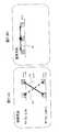
さらに他のパイロットシンボル配置として、例えば図13に示すように、あるフレーム時間において、パイロットシンボルを異なるシンボル時間に対して周波数方向にずらしながら配置する場合も考えられる。このような例として地上波放送向けの標準規格の1つであるDVB(Digital Video Broadcasting)-T標準規格があり、参考文献1として、“ETSI. Digitalbroadcasting systems for television, sound and data services: ETS 300744.1997.”がある。また、参考文献2として、“M.Speth,S.Fechtel, G.Fock, H.Meyr, "Broadband transmission using OFDM: systemperformance and receiver complexity,"BroadbandCommunications, 1998. Accessing, Transmission, Networking. Proceedings. 1998International Zurich Seminar on 17-19 Feb. 1998 Page(s):99-104”のfig.1にもパイロット信号配置が例示されている。(B3) Third Modification As another pilot symbol arrangement, for example, as shown in FIG. 13, a pilot symbol may be arranged while being shifted in the frequency direction with respect to a different symbol time in a certain frame time. An example of this is the DVB (Digital Video Broadcasting) -T standard, which is one of the standards for terrestrial broadcasting.
このようなパイロットシンボル配置の場合には、時間的に大きく離れたパイロットシンボルを用いるよりも、図13中に示すように、時間的により近い距離に配置されたパイロットシンボル、即ち、実線矢印53の両端に位置するパイロットシンボルどうしの平均値及び点線矢印54の両端に位置するパイロットシンボルどうしの平均値をそれぞれ演算し、それらの差分を用いて干渉雑音電力を推定する方が、より精度の高い推定が可能である。 In such a pilot symbol arrangement, rather than using pilot symbols that are far apart in time, as shown in FIG. 13, pilot symbols arranged closer to each other in time, that is,
例えば図13中に示すように、パイロットシンボルが2シンボル時間毎に周波数方向に2サブキャリア分ずつ周波数数方向にずらしながら配置されている場合、アンテナ#a,サブフレーム#nのシンボル番号=#t(tはシンボル時間で0以上の整数)の帯域端からi番目にマッピングされたパイロットシンボルをh(a,n,Mi,t)と表現すると、この場合の推定方法は、当該パイロットシンボルをパイロット抽出部25(図4参照)にて抽出して、パイロットパターンをキャンセルした信号とし、それらを用いてK回の平均化、及び、時間方向L+1列分の平均化で推定する場合、干渉雑音電力(雑音推定値)h(a,n)は、下記の(11)式で表すことができる。 For example, as shown in FIG. 13, when pilot symbols are arranged while shifting in the frequency direction by two subcarriers in the frequency direction every two symbol times, symbol numbers of antenna #a and subframe # n = # If the pilot symbol mapped i-th from the band edge of t (t is an integer of 0 or more in symbol time) is expressed as h (a, n, Mi, t), the estimation method in this case is that the pilot symbol is When the signal is extracted by the pilot extraction unit 25 (see FIG. 4) and the pilot pattern is canceled, and the estimation is performed by averaging K times and averaging for the L + 1 column in the time direction, The power (noise estimated value) h (a, n) can be expressed by the following equation (11).
この演算を図6と同様の要領で図示化すると図14に示すようになる。即ち、本例の推定方法では、同一受信アンテナ#aについて、
(1)或るサブフレーム#nにおいて、或るシンボル時間2tにサブキャリア#Miに配置されているパイロット信号h(a,n,Mi,2t)と、当該パイロット信号h(a,n,Mi,2t)に対して2シンボル時間だけ異なるシンボル時間(2t+2)で2サブキャリア分だけ異なる周波数(高周波数側)に隣接配置されているパイロット信号h(a,n,M(i+1),2t+2)との平均値を求める(パイロット平均化過程:符号261B(261b)参照)とともに、
(2)同じサブフレーム#nにおいて、前記パイロット信号h(a,n,Mi,2t)に対して周波数方向に2サブキャリア分だけ異なる周波数に配置されているパイロット信号h(a,n,M(i+1),2t)と、当該パイロット信号h(a,n,M(i+1),2t)に対して2シンボル時間だけ異なる時間(2t+2)で2サブキャリア分だけ異なる周波数(低周波数側)に配置されているパイロット信号h(a,n,Mi,2t+2)との平均値を求め(パイロット平均化過程:符号261B(261b)参照)、
(3)それらの平均値の差分を差分検出手段(過程)263bにて検出し電力化手段(過程)264bにて電力化することを、所定数のパイロット信号について行ない、それらの電力平均値を平均化手段(過程)265bにより干渉雑音電力の推定値として求める(干渉雑音電力推定過程:符号262B参照)のである。When this calculation is illustrated in the same manner as in FIG. 6, it is as shown in FIG. That is, in the estimation method of this example, for the same receiving antenna #a,
(1) In a certain subframe #n, a pilot signal h (a, n, Mi, 2t) arranged on the subcarrier #Mi at a
(2) In the same subframe #n, pilot signals h (a, n, M) arranged at frequencies different from the pilot signals h (a, n, Mi, 2t) by two subcarriers in the frequency direction. (I + 1), 2t) and a different frequency (low frequency side) by two subcarriers at a time (2t + 2) that differs by two symbol times with respect to the pilot signal h (a, n, M (i + 1), 2t). An average value with the arranged pilot signal h (a, n, Mi, 2t + 2) is obtained (refer to pilot averaging process: reference numeral 261B (261b)),
(3) The difference between the average values is detected by the difference detection means (process) 263b and is converted into electric power by the power generation means (process) 264b with respect to a predetermined number of pilot signals. It is obtained as an estimated value of interference noise power by the averaging means (process) 265b (interference noise power estimation process: see
(B4)第4変形例
複数のサブフレームをまとめてより大きなフレームが構成される場合、例えば図15に示すように、2サブフレームで1つのフレーム(1TTI=1ms)が構成されるような場合、必ずしもすべてのフレームにパイロットシンボルがマッピングされないことや、フレーム毎にパイロットシンボルの指向性等の特性が異なることがある。(B4) Fourth Modification When a larger frame is configured by combining a plurality of subframes, for example, when one frame (1 TTI = 1 ms) is configured by two subframes as shown in FIG. However, pilot symbols are not necessarily mapped to all frames, and characteristics such as directivity of pilot symbols may differ from frame to frame.
即ち、フレーム単位でユーザデータなどの割り当てを行なうパケットシステムなどにおいては、パイロット信号がデータ割り当てのあるフレームのみで送信され、次のフレームや前のフレーム(隣接フレーム)にはパイロット信号がマッピングされていない場合がある。また、指向性ビームや複数の送信方法を切り替えて使用できるようなシステムにおいては、各フレームでパイロット信号の指向性などが異なり、推定しようとする干渉電力そのものがフレーム毎に異なる場合がある。 That is, in a packet system that assigns user data or the like in frame units, pilot signals are transmitted only in frames with data assignment, and pilot signals are mapped to the next frame or the previous frame (adjacent frame). There may not be. Also, in a system in which a directional beam or a plurality of transmission methods can be switched and used, the directivity of the pilot signal is different in each frame, and the interference power itself to be estimated may be different for each frame.
このような場合には、図15中に、符号A,Bで示すようにフレーム内のパイロット信号(斜線部参照)に上述した推定方法のいずれかを適用し、符号Cで示すようなフレーム(サブフレームではない)を跨るような組み合わせのパイロット信号を用いた推定は行なわない方が好ましい。また、第1変形例で説明した複数回の推定値の平均化は、同一フレーム内の推定結果(A,B)に対してのみ行ない、異なるフレーム間の推定結果(C)に対しては行なわない方が、推定対象フレームの干渉雑音電力を正しく推定することができる。 In such a case, one of the estimation methods described above is applied to the pilot signal (see the hatched portion) in the frame as shown by reference signs A and B in FIG. It is preferable not to perform estimation using a combination of pilot signals across (not subframes). In addition, the averaging of the estimation values a plurality of times described in the first modification is performed only on the estimation results (A, B) in the same frame, and is performed on the estimation results (C) between different frames. If not, the interference noise power of the estimation target frame can be estimated correctly.
ここで、推定対象フレームの識別は、例えば、フレーム内のデータ割り当ての有無を示す情報や、指向性ビームの識別情報(直交符号の割り当て情報等)、送信方法に応じたパイロットシンボルのマッピング情報などの制御情報がフレーム毎あるいは数フレームおきにマッピングされている場合に、当該制御情報に基づいて実施することができる。
したがって、例えば図16に示すように、図4に示したOFDM受信機に、推定制御部28を付加し、当該推定制御部28にて、前記制御情報を受信フレームの復調処理部27による復調結果から取得し、当該制御情報に基づいて推定対象フレームを決定し、推定対象フレームと決定したフレームについてのみ干渉電力推定部26の推定結果を有効とし、それ以外のフレームについては当該推定結果を無効とするように干渉電力推定部26を制御することで、受信フレームに応じた推定結果の有効、無効の切り替えを実現して、干渉雑音電力の推定精度を向上することが可能となる。Here, the estimation target frame is identified by, for example, information indicating the presence / absence of data allocation in the frame, directional beam identification information (orthogonal code allocation information, etc.), pilot symbol mapping information according to the transmission method, etc. When the control information is mapped every frame or every several frames, the control information can be implemented based on the control information.
Therefore, for example, as shown in FIG. 16, an
つまり、本例の推定制御部28は、受信フレーム別に前記のパイロット平均化過程及び干渉雑音推定過程を実施するか否かを判断する判断手段としての機能と、この判断手段にて実施すると判断された受信フレーム内のパイロット信号のみを用いて前記のパイロット平均化過程及び干渉雑音推定過程を実施する制御手段としての機能とを兼ね備えているのである。 That is, it is determined that the
なお、上述した各変形例は適宜に組み合わせて重畳的、あるいは、選択的に実施してもよい。
〔C〕付記
(付記1)
所定の送信周波数帯域においてパイロット信号が異なる複数の周波数に配置されて周期的に送信されるマルチキャリア通信システムにおいて、
異なる時刻に異なる周波数で受信されたパイロット信号間の平均値を求めるパイロット平均化過程と、
前記パイロット平均化過程により得られた各平均値の差分に基づいて干渉雑音を推定する干渉雑音推定過程とを有することを特徴とする、マルチキャリア通信システムにおける干渉雑音推定方法。
(付記2)
前記パイロット平均化過程において、
時間及び周波数の2次元領域において、4つのパイロット信号の配置位置がなす四角形の2つの対角線の両端に位置するパイロット信号間の平均値を計算することを特徴とする、付記1記載のマルチキャリア通信システムにおける干渉雑音推定方法。
(付記3)
前記4つのパイロット信号が、前記2次元領域において時間方向に隣接する2つのパイロット信号と、前記2次元領域において周波数方向に隣接する2つのパイロット信号であることを特徴とする、付記2記載のマルチキャリア通信システムにおける干渉雑音推定方法。
(付記4)
前記4つのパイロット信号の配置位置がなす前記四角形が、平行四辺形であることを特徴とする、付記2又は3に記載のマルチキャリア通信システムにおける干渉雑音推定方法。
(付記5)
所定の送信周波数帯域においてパイロット信号が異なる複数の周波数に配置されて周期的に送信されるマルチキャリア通信システムにおいて、
異なる時刻に異なる周波数で受信されたパイロット信号間の平均値を求めるパイロット平均化過程と、
前記パイロット平均化過程により得られた各平均値の差分に基づいて干渉雑音を推定する干渉雑音推定過程と、
前記干渉雑音推定過程による推定結果に基づいてマルチキャリア復調処理を行なう復調処理過程とを有することを特徴とする、マルチキャリア通信システムにおける受信処理方法。
(付記6)
所定の送信周波数帯域においてパイロット信号が異なる複数の周波数に配置されて周期的に送信されるマルチキャリア通信システムにおける干渉雑音推定装置であって、
異なる時刻に異なる周波数で受信されたパイロット信号間の平均値を求めるパイロット平均化手段と、
前記パイロット平均化手段により得られた各平均値の差分に基づいて干渉雑音を推定する干渉雑音推定手段とをそなえたことを特徴とする、マルチキャリア通信システムにおける干渉雑音推定装置。
(付記7)
前記パイロット平均化手段が、
時間及び周波数の2次元領域において、4つのパイロット信号の配置位置がなす四角形の2つの対角線の両端に位置するパイロット信号間の平均値を計算する手段をそなえたことを特徴とする、付記6記載のマルチキャリア通信システムにおける干渉雑音推定装置。
(付記8)
前記4つのパイロット信号が、前記2次元領域において時間方向に隣接する2つのパイロット信号と、前記2次元領域において周波数方向に隣接する2つのパイロット信号であることを特徴とする、付記7記載のマルチキャリア通信システムにおける干渉雑音推定装置。
(付記9)
前記4つのパイロット信号の配置位置がなす前記四角形が、平行四辺形であることを特徴とする、付記7又は8に記載のマルチキャリア通信システムにおける干渉雑音推定装置。
(付記10)
所定の送信周波数帯域においてパイロット信号が異なる複数の周波数に配置されて周期的に送信されるマルチキャリア通信システムにおける受信機であって、
異なる時刻に異なる周波数で受信されたパイロット信号間の平均値を求めるパイロット平均化手段と、前記パイロット平均化手段により得られた各平均値の差分に基づいて干渉雑音を推定する干渉雑音推定手段とを有する干渉雑音推定装置と、
前記干渉雑音推定装置による推定結果に基づいてマルチキャリア復調処理を行なう復調処理手段とをそなえたことを特徴とする、マルチキャリア通信システムにおける受信機。
(付記11)
所定の送信周波数帯域においてパイロット信号が異なる複数の周波数に配置されて周期的に送信されるマルチキャリア通信システムにおいて、
異なる時刻に同じ周波数で受信されたパイロット信号と同じ時刻に異なる周波数で受信されたパイロット信号との平均値を求めるパイロット平均化過程と、
前記パイロット平均化過程により得られた各平均値の差分に基づいて干渉雑音を推定する干渉雑音推定過程とを有することを特徴とする、マルチキャリア通信システムにおける干渉雑音推定方法。
(付記12)
前記パイロット平均化過程を、4つの第1のパイロット信号及び4つの第2のパイロット信号のそれぞれについて実施し、
前記干渉雑音推定過程において前記第1及び第2のパイロット信号のそれぞれに関して得られた推定結果を平均化することを特徴とする、付記2記載のマルチキャリア通信システムにおける干渉雑音推定方法。
(付記13)
受信フレーム別に前記のパイロット平均化過程及び干渉雑音推定過程を実施するか否かを判断し、
実施すると判断した受信フレーム内のパイロット信号のみを用いて前記のパイロット平均化過程及び干渉雑音推定過程を実施することを特徴とする、付記1記載のマルチキャリア通信システムにおける干渉雑音推定方法。
(付記14)
所定の送信周波数帯域においてパイロット信号が異なる複数の周波数に配置されて周期的に送信されるマルチキャリア通信システムにおいて、
異なる時刻に同じ周波数で受信されたパイロット信号と同じ時刻に異なる周波数で受信されたパイロット信号との平均値を求めるパイロット平均化過程と、
前記パイロット平均化過程により得られた各平均値の差分に基づいて干渉雑音を推定する干渉雑音推定過程と、
前記干渉雑音推定過程による推定結果に基づいてマルチキャリア復調処理を行なう復調処理過程とを有することを特徴とする、マルチキャリア通信システムにおける受信処理方法。
(付記15)
所定の送信周波数帯域においてパイロット信号が異なる複数の周波数に配置されて周期的に送信されるマルチキャリア通信システムにおける干渉雑音推定装置であって、
異なる時刻に同じ周波数で受信されたパイロット信号と同じ時刻に異なる周波数で受信されたパイロット信号との平均値を求めるパイロット平均化手段と、
前記パイロット平均化手段により得られた各平均値の差分に基づいて干渉雑音を推定する干渉雑音推定手段とをそなえたことを特徴とする、マルチキャリア通信システムにおける干渉雑音推定装置。
(付記16)
前記パイロット平均化手段が、4つの第1のパイロット信号及び4つの第2のパイロット信号のそれぞれについて実施し、
前記干渉雑音推定手段が、前記第1及び第2のパイロット信号のそれぞれに関して得られた推定結果を平均化することを特徴とする、付記7記載のマルチキャリア通信システムにおける干渉雑音推定装置。
(付記17)
受信フレーム別に前記のパイロット平均化過程及び干渉雑音推定過程を実施するか否かを判断する判断手段と、
該判断手段にて実施すると判断された受信フレーム内のパイロット信号のみを用いて前記のパイロット平均化過程及び干渉雑音推定過程を実施する制御手段とをさらにそなえたことを特徴とする、付記6記載のマルチキャリア通信システムにおける干渉雑音推定装置。
(付記18)
所定の送信周波数帯域においてパイロット信号が異なる複数の周波数に配置されて周期的に送信されるマルチキャリア通信システムにおける受信機であって、
異なる時刻に同じ周波数で受信されたパイロット信号と同じ時刻に異なる周波数で受信されたパイロット信号との平均値を求めるパイロット平均化手段と、前記パイロット平均化手段により得られた各平均値の差分に基づいて干渉雑音を推定する干渉雑音推定手段とを有する干渉雑音推定装置と、
前記干渉雑音推定装置による推定結果に基づいてマルチキャリア復調処理を行なう復調処理手段とをそなえたことを特徴とする、マルチキャリア通信システムにおける受信機。Note that the above-described modifications may be appropriately combined and implemented in a superimposed manner or selectively.
[C] Appendix
(Appendix 1)
In a multicarrier communication system in which pilot signals are periodically transmitted by being arranged at a plurality of different frequencies in a predetermined transmission frequency band,
A pilot averaging process for obtaining an average value between pilot signals received at different frequencies at different times;
An interference noise estimation method in a multicarrier communication system, comprising: an interference noise estimation process for estimating interference noise based on a difference between average values obtained by the pilot averaging process.
(Appendix 2)
In the pilot averaging process,
The multicarrier communication according to
(Appendix 3)
The multi pilot according to
(Appendix 4)
The interference noise estimation method in the multicarrier communication system according to
(Appendix 5)
In a multicarrier communication system in which pilot signals are periodically transmitted by being arranged at a plurality of different frequencies in a predetermined transmission frequency band,
A pilot averaging process for obtaining an average value between pilot signals received at different frequencies at different times;
An interference noise estimation process for estimating interference noise based on the difference between the average values obtained by the pilot averaging process;
A reception processing method in a multicarrier communication system, comprising: a demodulation processing step of performing multicarrier demodulation processing based on an estimation result obtained by the interference noise estimation step.
(Appendix 6)
An interference noise estimation apparatus in a multicarrier communication system in which pilot signals are arranged at a plurality of different frequencies in a predetermined transmission frequency band and periodically transmitted,
Pilot averaging means for obtaining an average value between pilot signals received at different frequencies at different times;
An interference noise estimation apparatus in a multicarrier communication system, comprising: interference noise estimation means for estimating interference noise based on a difference between respective average values obtained by the pilot averaging means.
(Appendix 7)
The pilot averaging means comprises:
(Appendix 8)
The multiple pilot signals according to claim 7, wherein the four pilot signals are two pilot signals adjacent in the time direction in the two-dimensional region and two pilot signals adjacent in the frequency direction in the two-dimensional region. An interference noise estimation apparatus in a carrier communication system.
(Appendix 9)
9. The interference noise estimation apparatus for a multicarrier communication system according to appendix 7 or 8, wherein the quadrangle formed by the arrangement positions of the four pilot signals is a parallelogram.
(Appendix 10)
A receiver in a multicarrier communication system in which pilot signals are arranged at a plurality of different frequencies and transmitted periodically in a predetermined transmission frequency band,
Pilot averaging means for obtaining average values between pilot signals received at different frequencies at different times; and interference noise estimating means for estimating interference noise based on the difference between the average values obtained by the pilot averaging means; An interference noise estimation device comprising:
A receiver in a multicarrier communication system, comprising: demodulation processing means for performing multicarrier demodulation processing based on an estimation result by the interference noise estimation apparatus.
(Appendix 11)
In a multicarrier communication system in which pilot signals are periodically transmitted by being arranged at a plurality of different frequencies in a predetermined transmission frequency band,
A pilot averaging process for obtaining an average value of pilot signals received at the same frequency at different times and pilot signals received at different frequencies at the same time;
An interference noise estimation method in a multicarrier communication system, comprising: an interference noise estimation process for estimating interference noise based on a difference between average values obtained by the pilot averaging process.
(Appendix 12)
Performing the pilot averaging process on each of four first pilot signals and four second pilot signals;
The interference noise estimation method in the multicarrier communication system according to
(Appendix 13)
Determine whether to perform the pilot averaging process and the interference noise estimation process for each received frame;
The interference noise estimation method in the multicarrier communication system according to
(Appendix 14)
In a multicarrier communication system in which pilot signals are periodically transmitted by being arranged at a plurality of different frequencies in a predetermined transmission frequency band,
A pilot averaging process for obtaining an average value of pilot signals received at the same frequency at different times and pilot signals received at different frequencies at the same time;
An interference noise estimation process for estimating interference noise based on the difference between the average values obtained by the pilot averaging process;
A reception processing method in a multicarrier communication system, comprising: a demodulation processing step of performing multicarrier demodulation processing based on an estimation result obtained by the interference noise estimation step.
(Appendix 15)
An interference noise estimation apparatus in a multicarrier communication system in which pilot signals are arranged at a plurality of different frequencies in a predetermined transmission frequency band and periodically transmitted,
Pilot averaging means for obtaining an average value of pilot signals received at the same frequency at different times and pilot signals received at different frequencies at the same time;
An interference noise estimation apparatus in a multicarrier communication system, comprising: interference noise estimation means for estimating interference noise based on a difference between respective average values obtained by the pilot averaging means.
(Appendix 16)
The pilot averaging means is implemented for each of four first pilot signals and four second pilot signals;
8. The interference noise estimation apparatus in a multicarrier communication system according to appendix 7, wherein the interference noise estimation means averages the estimation results obtained for each of the first and second pilot signals.
(Appendix 17)
A determination means for determining whether to perform the pilot averaging process and the interference noise estimation process for each received frame;
(Appendix 18)
A receiver in a multicarrier communication system in which pilot signals are arranged at a plurality of different frequencies and transmitted periodically in a predetermined transmission frequency band,
A pilot averaging means for obtaining an average value between pilot signals received at the same frequency at different times and pilot signals received at different frequencies at the same time, and a difference between each average value obtained by the pilot averaging means An interference noise estimation device having interference noise estimation means for estimating interference noise based on
A receiver in a multicarrier communication system, comprising: demodulation processing means for performing multicarrier demodulation processing based on an estimation result by the interference noise estimation apparatus.
以上詳述したように、本発明によれば、周波数方向あるいは時間方向のチャネル変動が大きくても、精度良く干渉雑音の推定を行なうことができるので、無線通信技術分野に極めて有用と考えられる。 As described in detail above, according to the present invention, interference noise can be estimated with high accuracy even if the channel fluctuation in the frequency direction or the time direction is large. Therefore, it is considered extremely useful in the field of wireless communication technology.
Claims (8)
Translated fromJapanese異なる時刻に異なる周波数で受信されたパイロット信号間の平均値を求めるパイロット平均化過程と、
前記パイロット平均化過程により得られた各平均値の差分に基づいて干渉雑音を推定する干渉雑音推定過程とを有することを特徴とする、マルチキャリア通信システムにおける干渉雑音推定方法。In a multicarrier communication system in which pilot signals are periodically transmitted by being arranged at a plurality of different frequencies in a predetermined transmission frequency band,
A pilot averaging process for obtaining an average value between pilot signals received at different frequencies at different times;
An interference noise estimation method in a multicarrier communication system, comprising: an interference noise estimation process for estimating interference noise based on a difference between average values obtained by the pilot averaging process.
異なる時刻に異なる周波数で受信されたパイロット信号間の平均値を求めるパイロット平均化過程と、
前記パイロット平均化過程により得られた各平均値の差分に基づいて干渉雑音を推定する干渉雑音推定過程と、
前記干渉雑音推定過程による推定結果に基づいてマルチキャリア復調処理を行なう復調処理過程とを有することを特徴とする、マルチキャリア通信システムにおける受信処理方法。In a multicarrier communication system in which pilot signals are periodically transmitted by being arranged at a plurality of different frequencies in a predetermined transmission frequency band,
A pilot averaging process for obtaining an average value between pilot signals received at different frequencies at different times;
An interference noise estimation process for estimating interference noise based on the difference between the average values obtained by the pilot averaging process;
A reception processing method in a multicarrier communication system, comprising: a demodulation processing step of performing multicarrier demodulation processing based on an estimation result obtained by the interference noise estimation step.
異なる時刻に異なる周波数で受信されたパイロット信号間の平均値を求めるパイロット平均化手段と、
前記パイロット平均化手段により得られた各平均値の差分に基づいて干渉雑音を推定する干渉雑音推定手段とをそなえたことを特徴とする、マルチキャリア通信システムにおける干渉雑音推定装置。An interference noise estimation apparatus in a multicarrier communication system in which pilot signals are arranged at a plurality of different frequencies in a predetermined transmission frequency band and periodically transmitted,
Pilot averaging means for obtaining an average value between pilot signals received at different frequencies at different times;
An interference noise estimation apparatus in a multicarrier communication system, comprising: interference noise estimation means for estimating interference noise based on a difference between respective average values obtained by the pilot averaging means.
異なる時刻に異なる周波数で受信されたパイロット信号間の平均値を求めるパイロット平均化手段と、前記パイロット平均化手段により得られた各平均値の差分に基づいて干渉雑音を推定する干渉雑音推定手段とを有する干渉雑音推定装置と、
前記干渉雑音推定装置による推定結果に基づいてマルチキャリア復調処理を行なう復調処理手段とをそなえたことを特徴とする、マルチキャリア通信システムにおける受信機。A receiver in a multicarrier communication system in which pilot signals are arranged at a plurality of different frequencies and transmitted periodically in a predetermined transmission frequency band,
Pilot averaging means for obtaining average values between pilot signals received at different frequencies at different times; and interference noise estimating means for estimating interference noise based on the difference between the average values obtained by the pilot averaging means; An interference noise estimation device comprising:
A receiver in a multicarrier communication system, comprising: demodulation processing means for performing multicarrier demodulation processing based on an estimation result by the interference noise estimation apparatus.
異なる時刻に同じ周波数で受信されたパイロット信号と同じ時刻に異なる周波数で受信されたパイロット信号との平均値を求めるパイロット平均化過程と、
前記パイロット平均化過程により得られた各平均値の差分に基づいて干渉雑音を推定する干渉雑音推定過程とを有することを特徴とする、マルチキャリア通信システムにおける干渉雑音推定方法。In a multicarrier communication system in which pilot signals are periodically transmitted by being arranged at a plurality of different frequencies in a predetermined transmission frequency band,
A pilot averaging process for obtaining an average value of pilot signals received at the same frequency at different times and pilot signals received at different frequencies at the same time;
An interference noise estimation method in a multicarrier communication system, comprising: an interference noise estimation process for estimating interference noise based on a difference between average values obtained by the pilot averaging process.
異なる時刻に同じ周波数で受信されたパイロット信号と同じ時刻に異なる周波数で受信されたパイロット信号との平均値を求めるパイロット平均化過程と、
前記パイロット平均化過程により得られた各平均値の差分に基づいて干渉雑音を推定する干渉雑音推定過程と、
前記干渉雑音推定過程による推定結果に基づいてマルチキャリア復調処理を行なう復調処理過程とを有することを特徴とする、マルチキャリア通信システムにおける受信処理方法。In a multicarrier communication system in which pilot signals are periodically transmitted by being arranged at a plurality of different frequencies in a predetermined transmission frequency band,
A pilot averaging process for obtaining an average value of pilot signals received at the same frequency at different times and pilot signals received at different frequencies at the same time;
An interference noise estimation process for estimating interference noise based on the difference between the average values obtained by the pilot averaging process;
A reception processing method in a multicarrier communication system, comprising: a demodulation processing step of performing multicarrier demodulation processing based on an estimation result obtained by the interference noise estimation step.
異なる時刻に同じ周波数で受信されたパイロット信号と同じ時刻に異なる周波数で受信されたパイロット信号との平均値を求めるパイロット平均化手段と、
前記パイロット平均化手段により得られた各平均値の差分に基づいて干渉雑音を推定する干渉雑音推定手段とをそなえたことを特徴とする、マルチキャリア通信システムにおける干渉雑音推定装置。An interference noise estimation apparatus in a multicarrier communication system in which pilot signals are arranged at a plurality of different frequencies in a predetermined transmission frequency band and periodically transmitted,
Pilot averaging means for obtaining an average value of pilot signals received at the same frequency at different times and pilot signals received at different frequencies at the same time;
An interference noise estimation apparatus in a multicarrier communication system, comprising: interference noise estimation means for estimating interference noise based on a difference between respective average values obtained by the pilot averaging means.
異なる時刻に同じ周波数で受信されたパイロット信号と同じ時刻に異なる周波数で受信されたパイロット信号との平均値を求めるパイロット平均化手段と、前記パイロット平均化手段により得られた各平均値の差分に基づいて干渉雑音を推定する干渉雑音推定手段とを有する干渉雑音推定装置と、
前記干渉雑音推定装置による推定結果に基づいてマルチキャリア復調処理を行なう復調処理手段とをそなえたことを特徴とする、マルチキャリア通信システムにおける受信機。A receiver in a multicarrier communication system in which pilot signals are arranged at a plurality of different frequencies and transmitted periodically in a predetermined transmission frequency band,
A pilot averaging means for obtaining an average value between pilot signals received at the same frequency at different times and pilot signals received at different frequencies at the same time, and a difference between each average value obtained by the pilot averaging means An interference noise estimation device having interference noise estimation means for estimating interference noise based on
A receiver in a multicarrier communication system, comprising: demodulation processing means for performing multicarrier demodulation processing based on an estimation result by the interference noise estimation apparatus.
Applications Claiming Priority (3)
| Application Number | Priority Date | Filing Date | Title |
|---|---|---|---|
| JP2006202074 | 2006-07-25 | ||
| JP2006202074 | 2006-07-25 | ||
| PCT/JP2007/057110WO2008012967A1 (en) | 2006-07-25 | 2007-03-30 | Interference noise estimating method in multicarrier communication system, reception processing method, interference noise estimating device and receiver |
Publications (2)
| Publication Number | Publication Date |
|---|---|
| JPWO2008012967A1 JPWO2008012967A1 (en) | 2009-12-17 |
| JP4571997B2true JP4571997B2 (en) | 2010-10-27 |
Family
ID=38981283
Family Applications (1)
| Application Number | Title | Priority Date | Filing Date |
|---|---|---|---|
| JP2008526690AExpired - Fee RelatedJP4571997B2 (en) | 2006-07-25 | 2007-03-30 | Interference noise estimation method, reception processing method, interference noise estimation apparatus and receiver in a multicarrier communication system |
Country Status (6)
| Country | Link |
|---|---|
| US (1) | US8520749B2 (en) |
| EP (1) | EP2045940B1 (en) |
| JP (1) | JP4571997B2 (en) |
| KR (1) | KR101002815B1 (en) |
| CN (1) | CN101496325B (en) |
| WO (1) | WO2008012967A1 (en) |
Cited By (1)
| Publication number | Priority date | Publication date | Assignee | Title |
|---|---|---|---|---|
| JP2012170070A (en)* | 2011-02-11 | 2012-09-06 | Samsung Electronics Co Ltd | Method and apparatus for performing channel estimation in a wireless communication system |
Families Citing this family (20)
| Publication number | Priority date | Publication date | Assignee | Title |
|---|---|---|---|---|
| EP1542488A1 (en)* | 2003-12-12 | 2005-06-15 | Telefonaktiebolaget LM Ericsson (publ) | Method and apparatus for allocating a pilot signal adapted to the channel characteristics |
| JP4928487B2 (en)* | 2008-03-14 | 2012-05-09 | 日本電信電話株式会社 | Cooperative transmission system, cooperative transmission method and receiving station |
| WO2010082319A1 (en) | 2009-01-14 | 2010-07-22 | 富士通株式会社 | Device, method for estimating channel quality, and transmission method |
| US8750803B2 (en)* | 2009-06-17 | 2014-06-10 | Nokia Corporation | Interference cancellation for predictive signals |
| JP2011023782A (en)* | 2009-07-13 | 2011-02-03 | Pioneer Electronic Corp | Receiving device and method |
| JP5016006B2 (en)* | 2009-08-24 | 2012-09-05 | 株式会社エヌ・ティ・ティ・ドコモ | Reception apparatus and interference power estimation method |
| CN101719881B (en)* | 2009-12-07 | 2013-01-23 | 华为技术有限公司 | Estimation method and device of noise power as well as communication system |
| US9407409B2 (en)* | 2010-02-23 | 2016-08-02 | Qualcomm Incorporated | Channel state information reference signals |
| US8995589B1 (en)* | 2010-11-17 | 2015-03-31 | James Qiu | Channel estimation in a pilot assisted OFDM system |
| US8675586B2 (en)* | 2010-11-19 | 2014-03-18 | Aurora Wireless, Inc. | Systems and methods for channel tracking in OFDMA |
| CN103299564A (en)* | 2011-01-05 | 2013-09-11 | Nec卡西欧移动通信株式会社 | Mobile communication device and channel quality index estimation method |
| US9564980B2 (en) | 2011-09-09 | 2017-02-07 | Samsung Electronics Co., Ltd. | Mobile telecommunication system with noise ratio estimation mechanism and method of operation thereof |
| CN102420796B (en)* | 2011-12-21 | 2014-07-02 | 展讯通信(上海)有限公司 | Communication terminal, and noise estimation method and device thereof |
| JP5949169B2 (en)* | 2012-05-31 | 2016-07-06 | ソニー株式会社 | Receiving apparatus, receiving method, and program |
| EP2680517B1 (en) | 2012-06-28 | 2016-12-21 | Telefonaktiebolaget LM Ericsson (publ) | Channel spread estimation |
| EP2903227B1 (en)* | 2014-01-30 | 2018-10-17 | Sony Corporation | Method for operating a base station in a wireless radio network |
| KR20160048360A (en)* | 2014-10-24 | 2016-05-04 | 삼성전자주식회사 | method and apparatus for receiving a signal based on a measurement of interference |
| US10903951B2 (en)* | 2015-06-05 | 2021-01-26 | Futurewei Technologies, Inc. | Systems and methods for adaptive pilot allocation |
| CN108363076B (en)* | 2018-01-16 | 2021-09-10 | 北京理工大学 | System and method for estimating instantaneous frequency of man-made interference based on short-time Renyi entropy |
| CN116232436B (en)* | 2023-03-09 | 2024-06-18 | 四川九洲电器集团有限责任公司 | DVB-S2 signal demodulation method, demodulation device and receiver |
Citations (5)
| Publication number | Priority date | Publication date | Assignee | Title |
|---|---|---|---|---|
| JPH11252040A (en)* | 1998-03-04 | 1999-09-17 | Toshiba Corp | OFDM receiver |
| WO2003088538A1 (en)* | 2002-04-15 | 2003-10-23 | Matsushita Electric Industrial Co., Ltd. | Receiver and its receiving method |
| JP2003348046A (en)* | 2002-05-24 | 2003-12-05 | Mitsubishi Electric Corp | Radio communication system, communication apparatus and reception quality measurement method |
| WO2004073223A1 (en)* | 2003-02-17 | 2004-08-26 | Panasonic Mobile Communications Co., Ltd. | Noise power estimation method and noise power estimation device |
| JP2004364094A (en)* | 2003-06-06 | 2004-12-24 | Keio Gijuku | Multi-carrier receiver |
Family Cites Families (8)
| Publication number | Priority date | Publication date | Assignee | Title |
|---|---|---|---|---|
| US5521937A (en)* | 1993-10-08 | 1996-05-28 | Interdigital Technology Corporation | Multicarrier direct sequence spread system and method |
| US6985432B1 (en)* | 2000-01-28 | 2006-01-10 | Zion Hadad | OFDM communication channel |
| SE524289C2 (en) | 2002-07-15 | 2004-07-20 | Stock Of Sweden Ab | Vehicles and method for checking the stability against tipping of such |
| WO2005109711A1 (en)* | 2004-05-07 | 2005-11-17 | Matsushita Electric Industrial Co., Ltd. | Ofdm receiver apparatus and ofdm receiving method |
| US8135088B2 (en)* | 2005-03-07 | 2012-03-13 | Q1UALCOMM Incorporated | Pilot transmission and channel estimation for a communication system utilizing frequency division multiplexing |
| US8339930B2 (en)* | 2005-05-16 | 2012-12-25 | Qualcomm Incorporated | Pilot transmission and channel estimation with pilot weighting |
| US8331216B2 (en)* | 2005-08-09 | 2012-12-11 | Qualcomm Incorporated | Channel and interference estimation in single-carrier and multi-carrier frequency division multiple access systems |
| JP5231762B2 (en)* | 2007-07-02 | 2013-07-10 | 富士通株式会社 | Receiver and reception processing method |
- 2007
- 2007-03-30JPJP2008526690Apatent/JP4571997B2/ennot_activeExpired - Fee Related
- 2007-03-30KRKR1020097003458Apatent/KR101002815B1/ennot_activeExpired - Fee Related
- 2007-03-30CNCN2007800278373Apatent/CN101496325B/ennot_activeExpired - Fee Related
- 2007-03-30EPEP07740546.2Apatent/EP2045940B1/ennot_activeCeased
- 2007-03-30WOPCT/JP2007/057110patent/WO2008012967A1/ennot_activeCeased
- 2009
- 2009-01-23USUS12/358,417patent/US8520749B2/ennot_activeExpired - Fee Related
Patent Citations (5)
| Publication number | Priority date | Publication date | Assignee | Title |
|---|---|---|---|---|
| JPH11252040A (en)* | 1998-03-04 | 1999-09-17 | Toshiba Corp | OFDM receiver |
| WO2003088538A1 (en)* | 2002-04-15 | 2003-10-23 | Matsushita Electric Industrial Co., Ltd. | Receiver and its receiving method |
| JP2003348046A (en)* | 2002-05-24 | 2003-12-05 | Mitsubishi Electric Corp | Radio communication system, communication apparatus and reception quality measurement method |
| WO2004073223A1 (en)* | 2003-02-17 | 2004-08-26 | Panasonic Mobile Communications Co., Ltd. | Noise power estimation method and noise power estimation device |
| JP2004364094A (en)* | 2003-06-06 | 2004-12-24 | Keio Gijuku | Multi-carrier receiver |
Cited By (1)
| Publication number | Priority date | Publication date | Assignee | Title |
|---|---|---|---|---|
| JP2012170070A (en)* | 2011-02-11 | 2012-09-06 | Samsung Electronics Co Ltd | Method and apparatus for performing channel estimation in a wireless communication system |
Also Published As
| Publication number | Publication date |
|---|---|
| EP2045940B1 (en) | 2017-10-11 |
| CN101496325B (en) | 2012-07-04 |
| EP2045940A4 (en) | 2016-05-25 |
| KR101002815B1 (en) | 2010-12-21 |
| EP2045940A1 (en) | 2009-04-08 |
| CN101496325A (en) | 2009-07-29 |
| WO2008012967A1 (en) | 2008-01-31 |
| KR20090033399A (en) | 2009-04-02 |
| US8520749B2 (en) | 2013-08-27 |
| JPWO2008012967A1 (en) | 2009-12-17 |
| US20090141841A1 (en) | 2009-06-04 |
Similar Documents
| Publication | Publication Date | Title |
|---|---|---|
| JP4571997B2 (en) | Interference noise estimation method, reception processing method, interference noise estimation apparatus and receiver in a multicarrier communication system | |
| US10965389B2 (en) | OFDM system with reverse link interference estimation | |
| JP5024934B2 (en) | Wireless communication device | |
| US7706459B2 (en) | System and method for channel estimation | |
| US8619744B2 (en) | Reception method and receiver | |
| US7792226B2 (en) | Method and apparatus for carrier power and interference-noise estimation in space division multiple access and multiple-input/multiple-output wireless communication systems | |
| JP2004336746A (en) | Apparatus and method for estimating channel in orthogonal frequency division multiplexing system using multiple antennas | |
| KR100945419B1 (en) | Sliding Window Channel Estimator and Method in Broadband Wireless Communication System | |
| CN105122752A (en) | Device for estimating frequency offset in OFDM and method thereof | |
| JP4991593B2 (en) | Wireless communication device | |
| JP3910956B2 (en) | Propagation path estimator and receiving apparatus using the same for OFDM wireless communication system | |
| JP2008017144A (en) | Radio receiving apparatus and method | |
| EP1878136B1 (en) | An apparatus and method for receiving signals in multi-carrier multiple access systems | |
| JP4852551B2 (en) | Multicarrier receiver, multicarrier communication system, and demodulation method | |
| KR101181774B1 (en) | Method for allocating pilot signal in multi-carrier system | |
| CN110602014B (en) | Sampling time deviation estimation method based on LTE downlink reference signal | |
| WO2009157356A1 (en) | Radio communication device and signal transmission method in mimo radio communication | |
| KR101056276B1 (en) | Iterative IC Removal Method for Cooperative STBC-OPDM Systems | |
| JP2010056748A (en) | Method and device for estimating propagation path, and wireless receiver |
Legal Events
| Date | Code | Title | Description |
|---|---|---|---|
| TRDD | Decision of grant or rejection written | ||
| A01 | Written decision to grant a patent or to grant a registration (utility model) | Free format text:JAPANESE INTERMEDIATE CODE: A01 Effective date:20100727 | |
| A01 | Written decision to grant a patent or to grant a registration (utility model) | Free format text:JAPANESE INTERMEDIATE CODE: A01 | |
| A61 | First payment of annual fees (during grant procedure) | Free format text:JAPANESE INTERMEDIATE CODE: A61 Effective date:20100813 | |
| FPAY | Renewal fee payment (event date is renewal date of database) | Free format text:PAYMENT UNTIL: 20130820 Year of fee payment:3 | |
| R150 | Certificate of patent or registration of utility model | Free format text:JAPANESE INTERMEDIATE CODE: R150 Ref document number:4571997 Country of ref document:JP Free format text:JAPANESE INTERMEDIATE CODE: R150 | |
| LAPS | Cancellation because of no payment of annual fees |