JP4570966B2 - Cushion for breathing mask assembly - Google Patents
Cushion for breathing mask assemblyDownload PDFInfo
- Publication number
- JP4570966B2 JP4570966B2JP2004569779AJP2004569779AJP4570966B2JP 4570966 B2JP4570966 B2JP 4570966B2JP 2004569779 AJP2004569779 AJP 2004569779AJP 2004569779 AJP2004569779 AJP 2004569779AJP 4570966 B2JP4570966 B2JP 4570966B2
- Authority
- JP
- Japan
- Prior art keywords
- cushion
- face
- patient
- contact
- mask
- Prior art date
- Legal status (The legal status is an assumption and is not a legal conclusion. Google has not performed a legal analysis and makes no representation as to the accuracy of the status listed.)
- Expired - Fee Related
Links
- XDTMQSROBMDMFD-UHFFFAOYSA-NC1CCCCC1Chemical compoundC1CCCCC1XDTMQSROBMDMFD-UHFFFAOYSA-N0.000description1
Images


Classifications
- A—HUMAN NECESSITIES
- A61—MEDICAL OR VETERINARY SCIENCE; HYGIENE
- A61M—DEVICES FOR INTRODUCING MEDIA INTO, OR ONTO, THE BODY; DEVICES FOR TRANSDUCING BODY MEDIA OR FOR TAKING MEDIA FROM THE BODY; DEVICES FOR PRODUCING OR ENDING SLEEP OR STUPOR
- A61M16/00—Devices for influencing the respiratory system of patients by gas treatment, e.g. ventilators; Tracheal tubes
- A61M16/06—Respiratory or anaesthetic masks
- A61M16/0605—Means for improving the adaptation of the mask to the patient
- A61M16/0611—Means for improving the adaptation of the mask to the patient with a gusset portion
- A—HUMAN NECESSITIES
- A61—MEDICAL OR VETERINARY SCIENCE; HYGIENE
- A61M—DEVICES FOR INTRODUCING MEDIA INTO, OR ONTO, THE BODY; DEVICES FOR TRANSDUCING BODY MEDIA OR FOR TAKING MEDIA FROM THE BODY; DEVICES FOR PRODUCING OR ENDING SLEEP OR STUPOR
- A61M16/00—Devices for influencing the respiratory system of patients by gas treatment, e.g. ventilators; Tracheal tubes
- A61M16/06—Respiratory or anaesthetic masks
- A61M16/0605—Means for improving the adaptation of the mask to the patient
- A61M16/0616—Means for improving the adaptation of the mask to the patient with face sealing means comprising a flap or membrane projecting inwards, such that sealing increases with increasing inhalation gas pressure
- A61M16/0622—Means for improving the adaptation of the mask to the patient with face sealing means comprising a flap or membrane projecting inwards, such that sealing increases with increasing inhalation gas pressure having an underlying cushion
- A—HUMAN NECESSITIES
- A61—MEDICAL OR VETERINARY SCIENCE; HYGIENE
- A61M—DEVICES FOR INTRODUCING MEDIA INTO, OR ONTO, THE BODY; DEVICES FOR TRANSDUCING BODY MEDIA OR FOR TAKING MEDIA FROM THE BODY; DEVICES FOR PRODUCING OR ENDING SLEEP OR STUPOR
- A61M16/00—Devices for influencing the respiratory system of patients by gas treatment, e.g. ventilators; Tracheal tubes
- A61M16/06—Respiratory or anaesthetic masks
- A61M16/0605—Means for improving the adaptation of the mask to the patient
- A61M16/0633—Means for improving the adaptation of the mask to the patient with forehead support
- A61M16/0638—Means for improving the adaptation of the mask to the patient with forehead support in the form of a pivot
- A—HUMAN NECESSITIES
- A61—MEDICAL OR VETERINARY SCIENCE; HYGIENE
- A61M—DEVICES FOR INTRODUCING MEDIA INTO, OR ONTO, THE BODY; DEVICES FOR TRANSDUCING BODY MEDIA OR FOR TAKING MEDIA FROM THE BODY; DEVICES FOR PRODUCING OR ENDING SLEEP OR STUPOR
- A61M16/00—Devices for influencing the respiratory system of patients by gas treatment, e.g. ventilators; Tracheal tubes
- A61M16/06—Respiratory or anaesthetic masks
- A61M16/0683—Holding devices therefor
- A—HUMAN NECESSITIES
- A61—MEDICAL OR VETERINARY SCIENCE; HYGIENE
- A61M—DEVICES FOR INTRODUCING MEDIA INTO, OR ONTO, THE BODY; DEVICES FOR TRANSDUCING BODY MEDIA OR FOR TAKING MEDIA FROM THE BODY; DEVICES FOR PRODUCING OR ENDING SLEEP OR STUPOR
- A61M16/00—Devices for influencing the respiratory system of patients by gas treatment, e.g. ventilators; Tracheal tubes
- A61M16/08—Bellows; Connecting tubes ; Water traps; Patient circuits
- A61M16/0816—Joints or connectors
- A61M16/0825—Joints or connectors with ball-sockets
- Y—GENERAL TAGGING OF NEW TECHNOLOGICAL DEVELOPMENTS; GENERAL TAGGING OF CROSS-SECTIONAL TECHNOLOGIES SPANNING OVER SEVERAL SECTIONS OF THE IPC; TECHNICAL SUBJECTS COVERED BY FORMER USPC CROSS-REFERENCE ART COLLECTIONS [XRACs] AND DIGESTS
- Y10—TECHNICAL SUBJECTS COVERED BY FORMER USPC
- Y10T—TECHNICAL SUBJECTS COVERED BY FORMER US CLASSIFICATION
- Y10T29/00—Metal working
- Y10T29/49—Method of mechanical manufacture
- Y10T29/49826—Assembling or joining
- Y10T29/49863—Assembling or joining with prestressing of part
- Y10T29/4987—Elastic joining of parts
Landscapes
- Health & Medical Sciences (AREA)
- Emergency Medicine (AREA)
- Pulmonology (AREA)
- Engineering & Computer Science (AREA)
- Anesthesiology (AREA)
- Biomedical Technology (AREA)
- Heart & Thoracic Surgery (AREA)
- Hematology (AREA)
- Life Sciences & Earth Sciences (AREA)
- Animal Behavior & Ethology (AREA)
- General Health & Medical Sciences (AREA)
- Public Health (AREA)
- Veterinary Medicine (AREA)
- Respiratory Apparatuses And Protective Means (AREA)
Description
Translated fromJapanese 本出願は、2002年11月8日付けで出願された米国特許予備出願シリアル番号第60/424,686号明細書、2003年7月1日付けで出願された米国特許予備出願シリアル番号第60/483,622号明細書、および、2002年9月6日付けで出願された米国特許非予備出願シリアル番号第10/235,846号明細書、の優先権を主張するものである。米国特許非予備出願シリアル番号第10/235,846号明細書は、2001年9月7日付けで出願された米国特許予備出願シリアル番号第60/317,486号明細書、および、2001年12月28日付けで出願された米国特許予備出願シリアル番号第60/342,854号明細書、の優先権を主張するものである。これら文献の記載内容は、参考のため、ここに組み込まれる。 No. 60 / 424,686, filed Nov. 8, 2002, US Patent Application Serial No. 60, filed Jul. 1, 2003. No. 4,483,622 and US Patent No. 10 / 235,846, filed Sep. 6, 2002, are claimed. US patent
本発明は、例えば睡眠呼吸障害(SDB)に対する非侵襲性気道陽圧(NPPV)治療といったような、通気支援を提供するために使用される呼吸用マスクアセンブリのためのクッションに関するものである。 The present invention relates to a cushion for a respiratory mask assembly used to provide ventilatory assistance, such as non-invasive positive airway pressure (NPPV) treatment for sleep breathing disorders (SDB).
例えば睡眠無呼吸(OSA)といったようなSDBの処理のためのNPPVの使用は、Sullivan氏によって開発された(米国特許第4,944,310号明細書参照)。SDBの治療のための装置においては、ブロワを使用することによって、導管を介して患者インターフェースに対して加圧状態のエアを供給する。患者インターフェースは、様々な態様のものとすることができる。例えば、鼻用のマスクアセンブリとしたり、鼻と口とのためのマスクアセンブリとしたり、することができる。患者は、典型的には、NPPV治療を受ける際には、眠る間にマスクアセンブリを装着する。 The use of NPPV for the treatment of SDB, such as sleep apnea (OSA), was developed by Sullivan (see US Pat. No. 4,944,310). In an apparatus for treatment of SDB, a blower is used to supply pressurized air to a patient interface through a conduit. The patient interface can be of various aspects. For example, it can be a mask assembly for the nose or a mask assembly for the nose and mouth. Patients typically wear a mask assembly while sleeping when undergoing NPPV treatment.
マスクアセンブリは、典型的には、剛直なシェルすなわちフレームと、顔面接触用のソフトなクッションと、を備えている。クッションは、フレームと、患者の顔面と、の間にスペースを確保する。フレームとクッションとは、鼻を受領するキャビティ、あるいは、鼻と口とを受領するキャビティ、を形成する。フレームとクッションとは、ヘッドギアアセンブリによって、患者の顔面上で所定位置に保持される。ヘッドギアアセンブリは、典型的には、ストラップを備えており、このストラップは、患者の両側部を通って患者の後頭部へと巻回される。 The mask assembly typically includes a rigid shell or frame and a soft cushion for face contact. The cushion ensures a space between the frame and the patient's face. The frame and the cushion form a cavity for receiving the nose or a cavity for receiving the nose and mouth. The frame and cushion are held in place on the patient's face by the headgear assembly. The headgear assembly typically includes a strap that is wrapped around the patient's occipital region through both sides of the patient.
米国特許第5,243,971号明細書(Sullivan氏および Brudere氏)には、持続的気道陽圧法(CPAP)のための鼻用マスクアセンブリが開示されており、このアセンブリは、患者の鼻および顔面の輪郭に適合する膨張/成型シールを備えている。このマスクアセンブリは、シェルに対して取り付けられた顔面対向部分を有している。顔面対向部分は、患者の鼻領域を完全に覆い得るようなサイズおよび形状とされている。顔面対向部分は、膨張可能なメンブランとされ、弾性プラスチック材料から成型される。膨張可能なメンブランおよびシェルは、協働して、チャンバを形成する。チャンバ内へと加圧ガスを供給することにより、メンブランが、患者の顔面から外向きに膨らむ。この文献の記載内容は、参考のため、その全体がここに組み込まれる。 US Pat. No. 5,243,971 (Sullivan and Brudere) discloses a nasal mask assembly for continuous positive airway pressure (CPAP), which includes the patient's nose and It has an inflated / molded seal that matches the facial contour. The mask assembly has a face-facing portion attached to the shell. The face-facing portion is sized and shaped to completely cover the patient's nasal area. The face-facing portion is an inflatable membrane and is molded from an elastic plastic material. The inflatable membrane and shell cooperate to form a chamber. By supplying pressurized gas into the chamber, the membrane bulges outward from the patient's face. The contents of this document are incorporated herein in their entirety for reference.
米国特許第6,112,746号明細書(Kwok氏他)には、鼻用マスクアセンブリと、このマスクアセンブリのためのマスククッションと、が開示されている。クッションは、実質的に三角形状とされたフレームを備えている。このフレームから、メンブランが延出されている。フレームは、波形エッジを備えている。この波形エッジにより、マスクボディに対してクッションが固定される。メンブランは、患者の鼻を受領するための開口を備えている。メンブランは、フレームのリムから離間しており、メンブランの外表面は、実質的にリムと同じ形状とされている。この文献の記載内容は、参考のため、その全体がここに組み込まれる。 US Pat. No. 6,112,746 (Kwok et al.) Discloses a nasal mask assembly and a mask cushion for this mask assembly. The cushion includes a frame that is substantially triangular. The membrane extends from this frame. The frame has corrugated edges. With this waveform edge, the cushion is fixed to the mask body. The membrane has an opening for receiving the patient's nose. The membrane is spaced from the rim of the frame, and the outer surface of the membrane is substantially the same shape as the rim. The contents of this document are incorporated herein in their entirety for reference.
クッションを備えている従来のマスクアセンブリにおいては、シールは、クッションの接触ラインに沿って作用する接触力の結果として、クッションと患者の顔面との間に形成される。接触力は、典型的には、マスクアセンブリのフレームとクッションの壁とクッションのシール形成部分とを介して作用するヘッドギアストラップの張力の関数である。従来のマスクアセンブリにおいては、フレームは、鼻の少なくとも1つの部分を受領し得るよう構成されたキャビティまたは容積を形成する。クッションは、キャビティの周縁部分を形成する。したがって、使用時には、キャビティ内に位置した患者の顔面部分が、加圧状態とされたエアあるいは呼吸可能ガスに対して、曝される。よって、その加圧状態に基づく力を受ける。 In conventional mask assemblies having a cushion, a seal is formed between the cushion and the patient's face as a result of contact forces acting along the cushion contact line. Contact force is typically a function of the tension of the headgear strap acting through the frame of the mask assembly, the cushion wall and the seal-forming portion of the cushion. In conventional mask assemblies, the frame forms a cavity or volume configured to receive at least one portion of the nose. The cushion forms the peripheral portion of the cavity. Thus, in use, the patient's facial portion located within the cavity is exposed to pressurized air or breathable gas. Therefore, the force based on the pressurized state is received.
国際公開第01/97893号パンフレット(Frater氏他)として公開されたPCT特許出願AU01/00746号明細書には、患者に対してエアを供給するためのマスクアセンブリが開示されており、このアセンブリは、顔面に接触したクッションとマスクシェルとの間の相対移動を可能とする懸架機構を備えている。懸架機構は、また、クッションに対して、マスク圧力の関数としての力や、クッションの位置ズレの関数としての力や、これら双方の力、をもたらす。この文献の記載内容は、参考のため、その全体がここに組み込まれる。 PCT patent application AU01 / 00746, published as WO 01/97893 (Frater et al.), Discloses a mask assembly for supplying air to a patient. And a suspension mechanism that enables relative movement between the cushion in contact with the face and the mask shell. The suspension mechanism also provides the cushion with a force as a function of the mask pressure, a force as a function of the cushion misalignment, and both. The contents of this document are incorporated herein in their entirety for reference.
米国特許第5,074,297号明細書(Venegas 氏)には、断続的な陽圧呼吸治療に使用するための呼吸用マスクアセンブリが開示されている。このアセンブリは、患者の顔面と、呼吸用マスクの顔面ユニットと、の間のシールの形成および自動調整が可能と考えられている。呼吸用マスクアセンブリは、顔面ユニットと、この顔面ユニットに隣接した膨張可能ピストンと、このピストンの一端に取り付けられた剛直な支持構造と、患者に対してマスクアセンブリを固定するための取付機構と、を備えている。呼吸サイクルの吸気時には、マスクアセンブリ内が加圧状態とされ、その結果、ピストンが膨張する。取付機構と支持体とが、ピストンの膨張に対して十分に耐えることができ、患者の顔面に対して顔面ユニットを押圧する力が形成され、気密シールが維持される。マスクユニット内の圧力が減少したときには、顔面ユニット上接触力は、同様に減少し、シールが解除される。 U.S. Pat. No. 5,074,297 (Venegas) discloses a respiratory mask assembly for use in intermittent positive pressure breathing therapy. This assembly is believed to be capable of forming and automatically adjusting a seal between the patient's face and the respiratory mask face unit. A respiratory mask assembly includes a facial unit, an inflatable piston adjacent to the facial unit, a rigid support structure attached to one end of the piston, and an attachment mechanism for securing the mask assembly to a patient; It has. During inspiration of the respiratory cycle, the inside of the mask assembly is pressurized, and as a result, the piston expands. The attachment mechanism and the support can sufficiently withstand the expansion of the piston, a force is formed to press the face unit against the patient's face, and an airtight seal is maintained. When the pressure in the mask unit decreases, the contact force on the face unit also decreases and the seal is released.
米国特許第5,074,297号明細書、米国特許第5,243,971号明細書、米国特許第6,112,746号明細書、および、PCT特許出願AU01/00746号明細書に開示された従来技術によるマスクアセンブリに関する共通の問題点は、患者の快適性である。マスクアセンブリを数時間にわたって使用した後には、患者は、顔面上に、痛みを感じ、赤い痕跡が残る。患者の顔面の鼻のブリッジエリアは、特に敏感な場所として認識されている。 Disclosed in US Pat. No. 5,074,297, US Pat. No. 5,243,971, US Pat. No. 6,112,746, and PCT Patent Application AU01 / 00746. A common problem associated with prior art mask assemblies is patient comfort. After using the mask assembly for several hours, the patient feels pain and red marks on the face. The nose bridge area of the patient's face is recognized as a particularly sensitive location.
さらに、顔面接触部分は、着用者の顔面に過度の圧力を印加し、これにより、不快さを与えるとともに、場合によっては、皮膚に炎症を起こす。これは、顔面接触部分が、正常範囲の弾性を超えて捻られ、ある種の顔面輪郭になったときに、起こる。これにより、シールを得るためには、過度の力を印加する必要が生じる。場合によっては、このような過度の圧力や力が、着用者の顔面を、顔面接触部分に適合するように捻れさせる。これにより、着用者は、不快感を感じたり、顔面に痛みを感じたり、潰瘍形成を増加させる。 In addition, the face contact portion applies excessive pressure to the wearer's face, thereby causing discomfort and possibly causing skin irritation. This occurs when the face contact portion is twisted beyond the normal range of elasticity to a certain facial contour. Thereby, in order to obtain a seal, it is necessary to apply an excessive force. In some cases, such excessive pressure or force causes the wearer's face to twist to fit the face contact portion. This causes the wearer to feel uncomfortable, to feel pain on the face, and to increase ulcer formation.
従来技術におけるマスクアセンブリに関する他の共通の問題点は、マスクキャビティ内におけるCO2 の蓄積である。マスクアセンブリは、典型的には、ベント穴を備えている。このベント穴は、キャビティからの吐出ガスの連続的な排出を可能とするものである。吐出ガスの排出に影響する1つの要因は、マスクキャビティの内のデッドスペースである。Another common problem with mask assemblies in the prior art is the accumulation of CO2 in the mask cavity. The mask assembly typically includes a vent hole. This vent hole enables continuous discharge of the discharge gas from the cavity. One factor that affects discharge gas discharge is dead space within the mask cavity.
従来技術によるマスクに関する他の共通の問題点は、シールが不十分であることである。例えば、マスクは、睡眠時に着用者が寝返りをした際に、位置ズレを起こす可能性がある。これにより、ガス供給ラインに対して張力が発生し、この張力がマスクに伝達され、マスクと着用者との間のシールを破壊する。睡眠無呼吸という条件下で持続的気道陽圧法(CPAP)という治療のためにマスクが使用されている場合には、このようなリークにより、治療のための値に達しないような圧力しか、着用者の気道入口には、供給されなくなる。したがって、治療が無効なものとなる。 Another common problem with prior art masks is that the seal is inadequate. For example, the mask may cause displacement when the wearer turns over during sleep. This creates tension on the gas supply line, which is transmitted to the mask and breaks the seal between the mask and the wearer. If a mask is being used for the treatment of continuous positive airway pressure (CPAP) under sleep apnea conditions, such a leak will only cause pressure that does not reach the therapeutic value. It will no longer be supplied to the person's airway entrance. Therefore, treatment becomes ineffective.
ガセット部分を備えているマスクアセンブリに関する他の問題点は、視覚的なサイズであり、実際に明らかに大きい。 Another problem with mask assemblies with gusset portions is the visual size, which is actually obviously large.
よく起こることであるが、着用者が治療中にあごを移動させる場合、既存のフルフェイス型のマスクにおいては、他の問題点が生じる。その結果、エアリークが、口の下方において起こり、中央領域から、口の横またはコーナー領域へとリークが発生する。 As is often the case, other problems arise with existing full face masks when the wearer moves the chin during treatment. As a result, an air leak occurs below the mouth and leaks from the central area to the side or corner area of the mouth.
不快さを引き起こすことなくかつリークを最小化し得るようにして着用者の顔面を確実にシールし得るような、呼吸用マスクを構成することが要望されている。
本発明の1つの見地は、患者に対してより快適さをもたらし得るクッションを備えたマスクアセンブリを提供することである。 One aspect of the present invention is to provide a mask assembly with a cushion that can provide more comfort to the patient.
本発明の他の見地は、患者の顔面上にわたって顔面接触圧力を制御可能に分散させ得るクッションを備えたマスクアセンブリを提供することである。 Another aspect of the present invention is to provide a mask assembly with a cushion that can controllably distribute facial contact pressure over the patient's face.
本発明の他の見地は、患者の顔面の上の接触ライン回りにおいて顔面接触力を制御可能に分散する得るクッションを備えたマスクアセンブリを提供することである。 Another aspect of the present invention is to provide a mask assembly with a cushion that can controllably distribute facial contact forces around a contact line on the patient's face.
本発明の他の見地は、患者に対して呼吸可能なガスを供給し得る呼吸用マスクアセンブリを提供することである。本発明の一実施形態による呼吸用マスクアセンブリは、フレームと、クッションと、を具備している。クッションは、フレームに対して連結され得るよう構成された顔面非接触部分と、患者の顔面に対して係合し得るよう構成された顔面接触部分と、これら顔面非接触部分と顔面接触部分とを相互連結するための中間部分と、を備えている。中間部分は、顔面接触部分を介して患者の顔面に対して力の第1成分を印加し得るよう構成されたガセット部分を備えている。スプリング構造が、クッションの顔面接触部分に対して連結されている。スプリング構造は、顔面接触部分を介して患者の顔面に対して力の第2成分を印加する。ガセット部分およびスプリング構造によって印加された力の第1成分および第2成分は、それぞれ、顔面接触部分を介して患者の顔面に対して印加されるクッションによる接触力を決定する。 Another aspect of the present invention is to provide a respiratory mask assembly that can provide breathable gas to a patient. A respiratory mask assembly according to an embodiment of the present invention includes a frame and a cushion. The cushion includes a non-face contact portion configured to be coupled to the frame, a face contact portion configured to engage with the patient's face, and the non-face contact portion and the face contact portion. An intermediate portion for interconnecting. The intermediate portion includes a gusset portion configured to apply a first component of force to the patient's face via the face contact portion. A spring structure is connected to the face contact portion of the cushion. The spring structure applies a second component of force to the patient's face via the face contact portion. The first and second components of the force applied by the gusset portion and the spring structure, respectively, determine the contact force due to the cushion applied to the patient's face via the face contact portion.
本発明の他の見地は、患者の顔面の輪郭に追従し得る湾曲度合いを有したマスクアセンブリを提供することである。 Another aspect of the present invention is to provide a mask assembly having a degree of curvature that can follow the contours of the patient's face.
本発明の他の見地は、患者の視界に対する影響を最小化し得るガセット部分を備えたマスクアセンブリを提供することである。 Another aspect of the present invention is to provide a mask assembly with a gusset portion that can minimize the impact on the patient's field of view.
本発明の他の見地は、嵩が低いガセット部分を有したクッションを備えたマスクアセンブリを提供することである。 Another aspect of the present invention is to provide a mask assembly with a cushion having a gusset portion that is less bulky.
本発明の他の見地は、低圧でシールし得るとともに高圧では快適であるようなガセット部分を備えているマスクアセンブリを提供することである。 Another aspect of the present invention is to provide a mask assembly having a gusset portion that can be sealed at low pressure and comfortable at high pressure.
本発明の他の見地は、圧力分散を制御し得るよう、係止構造をもたらすガセット部分を有したクッションを備えたマスクアセンブリを提供することである。 Another aspect of the present invention is to provide a mask assembly with a cushion having a gusset portion that provides a locking structure so that pressure distribution can be controlled.
本発明の他の見地は、付加的投影面積をもたらすガセット部分と、ばね定数を有したスプリング構造と、を備えたマスクアセンブリであって、クッションからの顔面上への押圧力を、付加的投影面積と、マスク圧力と、スプリング構造のばね定数と、によって制御し得るものとされたマスクアセンブリを提供することである。 Another aspect of the present invention is a mask assembly comprising a gusset portion that provides an additional projected area and a spring structure having a spring constant, wherein the pressing force from the cushion onto the face is additionally projected. It is to provide a mask assembly that can be controlled by area, mask pressure, and spring constant of the spring structure.
本発明の他の見地は、クッションに対して弾性カフを付与することである。弾性カフは、クッションの残部の弾性係数より大きな弾性係数を有することができる。これにより、局所的な圧力に応答して、および/または、マスクと着用者の顔面との間の力の変化に応答して、非常に容易に変形したり引き伸ばされたりすることができる。これにより、患者が動いた場合であっても、シールの性能低下を回避することができる。弾性カフは、クッションの顔面接触部分と顔面非接触部分との間の中間部分に沿って、クッションに対して一体部材として形成することができる。弾性カフは、また、クッションとは別部材として形成することもできる。この場合には、弾性カフは、クッションの顔面接触部分に対しておよび/または顔面非接触部分に対して、組み付けることができる。 Another aspect of the present invention is to provide an elastic cuff to the cushion. The elastic cuff can have a modulus of elasticity that is greater than the modulus of elasticity of the remainder of the cushion. This can be very easily deformed and stretched in response to local pressure and / or in response to a change in force between the mask and the wearer's face. Thereby, even if a patient moves, the performance degradation of a seal can be avoided. The elastic cuff can be formed as an integral member with respect to the cushion along an intermediate portion between the face contact portion and the non-face contact portion of the cushion. The elastic cuff can also be formed as a separate member from the cushion. In this case, the elastic cuff can be assembled to the face contact portion and / or to the non-face contact portion of the cushion.
本発明の実施形態におけるさらなる見地は、着用者の顔面に対して安定的にかつ信頼性高くシールを形成し得るクッションを備えたフルフェイス型マスクを提供することである。 A further aspect in embodiments of the present invention is to provide a full-face mask with a cushion that can form a stable and reliable seal against the wearer's face.
本発明の実施形態の付加的な見地は、下唇の下部においておよび/または両側部において直接的に有効なシールを形成し得るようなフルフェイス型マスクを提供することである。 An additional aspect of embodiments of the present invention is to provide a full face mask that can form an effective seal directly on the lower lip and / or on both sides.
本発明の実施形態のさらなる見地は、比較的高圧でもって有効なシールを形成し得るようなフルフェイス型マスクを提供することである。 A further aspect of embodiments of the present invention is to provide a full face mask that can form an effective seal with relatively high pressure.
本発明の実施形態の他の見地は、着用者の顔面の骨領域に対して安定的に当接し得るようなフルフェイス型マスクを提供することである。 Another aspect of embodiments of the present invention is to provide a full-face mask that can stably abut against the bone region of the wearer's face.
本発明の実施形態のさらなる見地は、口よりも下側において顔面の骨構造の天然骨格に対して追従し得るようなフルフェイス型マスクを提供することである。 A further aspect of embodiments of the present invention is to provide a full face mask that can follow the natural skeleton of the facial bone structure below the mouth.
一例においては、フルフェイス型呼吸用マスクは、呼吸可能ガス用のポートと、クッションと、を具備している。フレームは、着用者の鼻孔領域および口を受領する内部チャンバを形成する。クッションは、フレームに対して連結されたフランジと、フレームの内部のチャンバに対する開口を形成する内周リムと、フランジと内周リムとの間に配置されかつ着用者の顔面に対して接触するシール部分と、を備えている。シール部分は、着用者の鼻孔上において着用者の顔面上に延在する鼻孔シール領域と、この鼻孔シール領域の両サイドから着用者の口の両サイドにまで延在する側部シール領域と、これら側部シール領域どうしの間にわたって延在する顎シール領域と、を有している。顎シール領域は、顎の骨の輪郭に対して追従し得るようにして、アーチ形状をなして上向きに湾曲している。 In one example, a full-face breathing mask includes a breathable gas port and a cushion. The frame forms an interior chamber that receives the wearer's nostril region and mouth. The cushion includes a flange connected to the frame, an inner peripheral rim that forms an opening to a chamber inside the frame, and a seal disposed between the flange and the inner peripheral rim and in contact with the wearer's face And a portion. The seal portion includes a nostril seal region extending on the wearer's face on the wearer's nostril, and a side seal region extending from both sides of the nostril seal region to both sides of the wearer's mouth, A chin seal region extending between the side seal regions. The chin seal area is curved upwardly in an arch shape so that it can follow the contour of the jaw bone.
他の例においては、フルフェイス型呼吸用マスクにおいて使用するためのクッションは、マスクフレームに対する連結用のフランジと、着用者の鼻孔および口を囲むような開口を形成する内周リムと、フランジと内周リムとの間に配置されかつ着用者の顔面に対して接触するシール部分と、を備えている。シール部分は、着用者の鼻孔上において着用者の顔面上に延在する鼻孔シール領域と、この鼻孔シール領域の両サイドから着用者の口の両サイドにまで延在する側部シール領域と、これら側部シール領域どうしの間にわたって延在する顎シール領域と、を有し、顎シール領域は、顎の骨の輪郭に対して追従し得るようにして、アーチ形状をなして上向きに湾曲している。 In another example, a cushion for use in a full face respirator includes a flange for connection to the mask frame, an inner peripheral rim that forms an opening surrounding the nostril and mouth of the wearer, and a flange. A seal portion disposed between the inner peripheral rim and contacting the face of the wearer. The seal portion includes a nostril seal region extending on the wearer's face on the wearer's nostril, and a side seal region extending from both sides of the nostril seal region to both sides of the wearer's mouth, A jaw seal region extending between the side seal regions, the jaw seal region being curved upwardly in an arched shape so that it can follow the contours of the jaw bone. ing.
これら実施例の原理は、呼吸用マスク上において使用するための任意のタイプのクッションに対して適用することができる。クッションは、限定するものではないけれども、シリコーンエラストマーや、ゲルや、発泡体や、あるいは、これらの任意の組合せを備えることができる。 The principles of these embodiments can be applied to any type of cushion for use on a respiratory mask. The cushion can comprise, but is not limited to, a silicone elastomer, a gel, a foam, or any combination thereof.
これら実施例の原理は、例えば人工呼吸器といったように、CPAPシステムやあるいは非陽圧呼吸用マスクも含めて、任意のタイプの呼吸用マスクに対して適用することができる。 The principles of these embodiments can be applied to any type of respirator, including CPAP systems or non-positive pressure respirators, such as ventilators.
本発明の他の見地や特徴点や利点は、添付図面を参照しつつ、本発明を何ら限定するものではなく単なる例示としての好ましい実施形態に関する以下の詳細な説明を読むことにより、明瞭となるであろう。 Other aspects, features and advantages of the present invention will become apparent upon reading the following detailed description of the preferred embodiment, which is merely exemplary and not limiting, with reference to the accompanying drawings. Will.
添付図面は、本発明の様々な実施形態の理解を容易なものとする。 The accompanying drawings facilitate an understanding of the various embodiments of this invention.
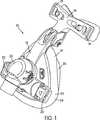
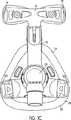
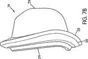
図1〜図5Bは、呼吸用マスクアセンブリ(10)を示している。このアセンブリ(10)は、フレーム(12)と、クッション(14)と、を備えている。クッション(14)は、フレーム(12)に対して、恒久的に連結することも、また、着脱可能に連結することも、できる。額支持部材(16)は、フレーム(12)の上部に対して、着脱可能に取り付けられている。ヘッドギアアセンブリ(図示せず)は、フレーム(12)に対して着脱可能に取り付けることができ、フレーム(12)とクッション(14)とを、患者の顔面上において、所望に調節された位置に維持することができる。例えば、ヘッドギアアセンブリは、一対をなす上ストラップおよび下ストラップを備えることができる。この場合、上ストラップは、額支持部材(16)上に設けられたクリップ構造(18)に対して着脱可能に連結され、一方、下ストラップは、フレーム(12)上に設けられたクリップ構造(20)に対して着脱可能に連結される。しかしながら、ヘッドギアアセンブリおよびフレーム(12)は、任意の適切な方法で互いに着脱可能に連結することができる。 1-5B show a respiratory mask assembly (10). The assembly (10) includes a frame (12) and a cushion (14). The cushion (14) can be permanently connected to the frame (12) or detachably connected. The forehead support member (16) is detachably attached to the upper portion of the frame (12). A headgear assembly (not shown) can be removably attached to the frame (12) to maintain the frame (12) and cushion (14) in a desired adjusted position on the patient's face. can do. For example, the headgear assembly can include a pair of upper and lower straps. In this case, the upper strap is detachably connected to the clip structure (18) provided on the forehead support member (16), while the lower strap is provided on the clip structure (18) provided on the frame (12). 20) is detachably connected to the device. However, the headgear assembly and frame (12) can be removably coupled to each other in any suitable manner.
図示の実施形態においては、マスクアセンブリ(10)は、患者の鼻に対して、呼吸可能なガスを供給するための鼻用のマスク構造である。しかしながら、マスクアセンブリ(10)は、鼻と口とに対するマスクすることができる、すなわち、フルフェイス型のマスクとすることができる。 In the illustrated embodiment, the mask assembly (10) is a nasal mask structure for supplying breathable gas to the patient's nose. However, the mask assembly (10) can be masked against the nose and mouth, i.e. it can be a full face mask.
旋回可能なエルボーアセンブリ(22)が、フレーム(12)の前方部分に対して着脱可能に取り付けられている。このエルボーアセンブリ(22)は、加圧供給源に対して連結された導管に対して連結可能であるように、構成されている。加圧供給源は、導管およのびエルボーアセンブリ(22)を介してクッション(14)内へと、呼吸可能なガスを供給し、これにより、患者は、呼吸を行うことができる。 A pivotable elbow assembly (22) is detachably attached to the front portion of the frame (12). The elbow assembly (22) is configured to be connectable to a conduit that is connected to a pressurized source. The pressurized source supplies breathable gas through the conduit and elbow assembly (22) and into the cushion (14) so that the patient can breathe.
図1〜図9Bに示すように、クッション(14)は、フレーム(12)に対して連結され得るよう構成された顔面非接触部分(24)(図6および6C)と、患者の顔面に対して係合し得るよう構成された顔面接触部分(26)と、顔面非接触部分(24)および顔面接触部分(26)を相互連結させる中間部分(28)と、を備えている。クッション(14)のシール形成部分(68)(図10B参照)は、患者の顔面上においてシールを形成し得るよう構成されている。クッション(14)は、詳細に後述するように、シール形成部分(68)に沿って接触力を印加することにより、シールを達成する。1つの態様においては、シール形成部分(68)は、面積を有したストリップである。例えば、患者の顔面に対して接触するストリップ(68)は、図10Bにおいて2本の破線で囲まれた面積を有することができる。患者の顔面上の敏感な領域に対して印加された接触力を、最小化することができる。患者の顔面のいくつかの部分は、快適性とシールとのバランスを達成するためには、特別の注意が必要である。 As shown in FIGS. 1-9B, the cushion (14) has a non-facial face (24) (FIGS. 6 and 6C) configured to be coupled to the frame (12) and the patient's face. A face contact portion (26) configured to be engageable with each other and an intermediate portion (28) interconnecting the face non-contact portion (24) and the face contact portion (26). The seal forming portion (68) (see FIG. 10B) of the cushion (14) is configured to form a seal on the patient's face. The cushion (14) achieves a seal by applying a contact force along the seal forming portion (68), as described in detail below. In one embodiment, the seal forming portion (68) is a strip having an area. For example, the strip (68) that contacts the patient's face can have an area surrounded by two dashed lines in FIG. 10B. Contact force applied to sensitive areas on the patient's face can be minimized. Some parts of the patient's face require special care in order to achieve a balance between comfort and sealing.
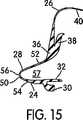
図示の実施形態においては、クッション(14)の顔面非接触部分(24)は、フレーム(12)に対して着脱可能に取り付けられる。例えば、図3、3B、6、6C、15に示すように、顔面非接触部分(24)は、ショルダ(30)とフランジ(32)と、を備えている。クッションクリップ(34)(図2、2B、3、3B参照)は、フレーム(12)に対して着脱可能に係合する。これにより、ショルダ(30)が、クリップ(34)とフレーム(12)の間に配置され、これにより、フレーム(12)に対してクッション(14)を取り付けることができる。これに関しては、例えば、本出願人による出願であるとともに現在係属中の、2002年9月6日付けで出願された米国特許予備出願シリアル番号第10/235,846号明細書を参照されたい。この文献の記載内容は、参考のため、その全体がここに組み込まれる。さらに、フランジ(32)は、シールを提供し得るようにして、配置される。代替的には、クッション(14)の顔面非接触部分(24)は、当該技術分野においては公知であるように、ストラップや、摩擦係合や、タングとグルーブとを備えた構成や、これらの組合せを使用することにより、フレーム(12)に対して着脱可能に取り付けることができる。しかしながら、クッション(14)の顔面非接触部分(24)は、例えば接着剤や機械的固定手段を使用して、フレーム(12)に対して恒久的に取り付けることもできる。 In the illustrated embodiment, the non-face contact portion (24) of the cushion (14) is detachably attached to the frame (12). For example, as shown in FIGS. 3, 3B, 6, 6C, and 15, the non-face contact portion (24) includes a shoulder (30) and a flange (32). The cushion clip (34) (see FIGS. 2, 2B, 3, 3B) is detachably engaged with the frame (12). Thereby, the shoulder (30) is arrange | positioned between a clip (34) and a flame | frame (12), and, thereby, a cushion (14) can be attached with respect to a flame | frame (12). In this regard, see, for example, US Patent Application Serial No. 10 / 235,846, filed September 6, 2002, filed by the present applicant and pending. The contents of this document are incorporated herein in their entirety for reference. Furthermore, the flange (32) is arranged in such a way that it can provide a seal. Alternatively, the non-face contact portion (24) of the cushion (14) may be configured with straps, frictional engagement, tongues and grooves, as known in the art, By using the combination, it can be detachably attached to the frame (12). However, the non-face contact portion (24) of the cushion (14) can also be permanently attached to the frame (12) using, for example, an adhesive or mechanical fastening means.
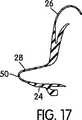
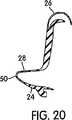
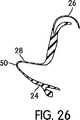
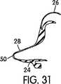
図6、6C、14〜33に示すように、クッション(14)の好ましい顔面接触部分(26)は、側壁(36)と、この側壁(36)から離間する向きに延出されたリム(38)と、実質的にリム(38)を囲むようにして設けられたメンブラン(40)と、を備えている。例えば、Kwok氏他による米国特許第6,112,746号明細書や、2002年8月12日付けで出願された米国特許予備出願シリアル番号第60/402,509号明細書を参照されたい。これら文献の記載内容は、参考のため、ここに組み込まれる。リム(38)および側壁(36)は、顔面接触部分(26)のための支持構造を提供し、また、メンブラン(40)は、顔面接触部分(26)に対するシール構造を提供する。 As shown in FIGS. 6, 6C, 14-33, the preferred face contact portion (26) of the cushion (14) includes a side wall (36) and a rim (38) extending away from the side wall (36). ) And a membrane (40) provided so as to substantially surround the rim (38). See, for example, U.S. Patent No. 6,112,746 by Kwok et al. And U.S. Patent Application Serial No. 60 / 402,509 filed August 12,2002. The contents of these documents are incorporated herein for reference. The rim (38) and side wall (36) provide a support structure for the face contact portion (26), and the membrane (40) provides a sealing structure for the face contact portion (26).
メンブラン(40)は、大きな実効的ロールオーバー部分(大きな半径)を提供し、これにより、マスクアセンブリ(10)は、患者の顔面に対しての、ある程度の移動や回転が可能とされ、なおかつ、メンブランの先端エッジが、患者の顔面を刺激することを防止する。さらに、メンブラン(40)は、リム(38)のエッジを超えてさらに延出されており、これにより、リム(38)が刺激の原因となることを防止している。 The membrane (40) provides a large effective rollover portion (large radius), which allows the mask assembly (10) to move and rotate to some extent relative to the patient's face, and The leading edge of the membrane prevents irritation to the patient's face. Furthermore, the membrane (40) extends further beyond the edge of the rim (38), thereby preventing the rim (38) from causing irritation.
リム(38)は、クッション(14)の鼻腔の内部へと内方に湾曲するような湾曲形状を有している。メンブラン(40)がリム(38)より薄いことは望ましいけれども、それらは、互いに同じ厚さとすることができる。 The rim (38) has a curved shape that curves inwardly into the nasal cavity of the cushion (14). Although it is desirable for the membrane (40) to be thinner than the rim (38), they can be the same thickness as each other.
メンブラン(40)の内表面は、リム(38)の外表面から離間している。これにより、患者に対してソフトなシールを形成することができる。ソフトなシールという用語は、メンブラン(40)が、不適切な力をもたらすことなく患者の顔面特徴物や鼻特徴物の形状に関しての小さな変化を許容し得ること、および、使用時には、有効なシールを維持しつつも、患者に対してのマスクのわずかな移動を許容し得ること、を意味している。リム(38)とメンブラン(40)との間の間隔は、患者の顔面上の様々な場所において互いに異なるものとすることができる。 The inner surface of the membrane (40) is spaced from the outer surface of the rim (38). Thereby, a soft seal can be formed for the patient. The term soft seal means that the membrane (40) can tolerate minor changes in the shape of the patient's facial and nasal features without causing inadequate force, and is an effective seal in use. Means that slight movement of the mask relative to the patient can be allowed. The spacing between the rim (38) and the membrane (40) can be different from each other at various locations on the patient's face.
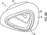
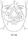
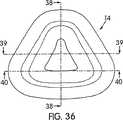
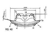
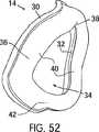
図2、2B、10〜11Bに示すように、クッション(14)の顔面接触部分(26)は、好ましくは、全体的に三角形状とされ、患者の鼻のブリッジ領域と頬領域とおよび唇領域とに対して接触し得るよう構成されている。しかしながら、顔面接触部分(26)は、他の任意の適切な形状とすることができる。例えば、全体的に台形形状とすることもできる。図示の実施形態においては、クッション(14)は、頬と鼻側面との間の皺のところにおいてシールを形成するための一対をなす頬領域(44)と;患者の鼻の下部と上唇の上部とのところにおいてシールを形成するための提供するための唇領域(46)と;鼻ブリッジ領域(42)と;を備えている。鼻ブリッジ領域(42)は、ブリッジを横切って延在しているとともに、ブリッジの側面に沿って傾斜しており、頬と鼻側面との間に形成された皺と交差している。唇領域(46)と各頬領域(44)との間の遷移領域は、鼻の底部の回りで鼻の側面に向けてクッション(14)が回転し始める場所である。鼻ブリッジ領域(42)と各頬領域(44)との間の遷移領域は、各頬領域(44)が鼻のブリッジに向けて上向きに曲がる場所である。言い換えれば、鼻ブリッジ領域(42)は、頬領域(44)が上向きに角度を変え始めるところから、スタートする。図40に示すように、メンブラン(40)は、患者の鼻のブリッジ領域(42)のところに、予成形されたノッチ(48)を備えることができる。このノッチ(48)は、患者の鼻のブリッジ領域の典型的な形状に全体的に適合する。 As shown in FIGS. 2, 2B, 10-11B, the face contact portion (26) of the cushion (14) is preferably generally triangular, with the patient's nasal bridge region, cheek region, and lip region. It is comprised so that it can contact with. However, the face contact portion (26) can be any other suitable shape. For example, it may be a trapezoidal shape as a whole. In the illustrated embodiment, the cushion (14) includes a pair of cheek areas (44) for forming a seal at the fold between the cheek and the nasal side; the lower part of the patient's nose and the upper part of the upper lip And a lip region (46) for providing a seal, and a nasal bridge region (42). The nasal bridge region (42) extends across the bridge and is inclined along the side of the bridge, intersecting the fold formed between the cheek and the nasal side. The transition region between the lip region (46) and each cheek region (44) is where the cushion (14) begins to rotate around the bottom of the nose and toward the side of the nose. The transition region between the nose bridge region (42) and each cheek region (44) is where each cheek region (44) bends upward toward the bridge of the nose. In other words, the nose bridge region (42) starts from where the cheek region (44) begins to change angle upward. As shown in FIG. 40, the membrane (40) may include a pre-formed notch (48) at the bridge region (42) of the patient's nose. This notch (48) generally conforms to the typical shape of the patient's nasal bridge region.
クッション(14)は、ガセット部分(50)を備えるものであって、顔面の湾曲度合いに全体的に適合し得るように湾曲している。図4〜5B、7〜9Bを、参照されたい。上記構成の利点は、高さが低減されていること、安定性が増大されていること、患者の顔面への適合度合いがより良好であること、および、視覚的なインパクトが低減されていること、である。他の利点は、フレーム(12)の側面においてヘッドギアクリップの突出度合いが低減されていることである。従来技術においては、ヘッドギアクリップが突出している。他の利点は、シリコーンの重量および容積が低減されていること、および、デッドスペースが低減されていること、および、ガセット部分が硬いものとされていてガセット部分の形状維持性能が良好なこと、である。 The cushion (14) includes a gusset portion (50), and is curved so as to be able to conform to the degree of curvature of the face as a whole. See FIGS. 4-5B, 7-9B. The advantages of the above configuration are reduced height, increased stability, better fit to the patient's face, and reduced visual impact. . Another advantage is that the degree of protrusion of the headgear clip is reduced on the side of the frame (12). In the prior art, the headgear clip protrudes. Other advantages include reduced silicone weight and volume, reduced dead space, and better gusseted shape-maintaining performance because the gusseted portion is harder, It is.
図示の実施形態においては、メンブラン(40)は、患者の鼻のブリッジ領域の上部に対して接触し得るよう構成されている。しかしながら、メンブラン(40)は、鼻のブリッジ領域よりも下の部分に対して接触することができる。例えば、2002年8月12日付けで出願された米国特許予備出願シリアル番号第60/402,509号明細書を参照されたい。この文献の記載内容は、参考のため、その全体がここに組み込まれる。 In the illustrated embodiment, the membrane (40) is configured to contact the top of the bridge region of the patient's nose. However, the membrane (40) can contact the portion below the nasal bridge region. See, for example, US Patent Preliminary Application Serial No. 60 / 402,509, filed Aug. 12, 2002. The contents of this document are incorporated herein in their entirety for reference.
図示の実施形態においては、クッション(14)の顔面接触部分(26)は、二重壁構成とされている。例えば、1つのメンブラン(40)と、1つのリム(38)と、を備えている。しかしながら、クッション(14)は、単一壁構成や、三重壁構成や、さらなる多重壁構成、とすることができる。例えば、メンブランおよびリムと組み合わされたクッションを提供することができる。例えば、単一壁構成とすることができる。これとは異なり、リムによる支持機能は、単一のメンブランの支持に関して、2つ以上の支持リムを使用して達成することができる。あるいは、1つのリムに対して、2つ以上のメンブランを設けることができる。他の代替可能な例においては、リムによる支持機能と、メンブランによるシール機能とは、2つの個別の部材へと分割することができる。これら部材は、互いに異なる材料から形成することができる。例えば、一方の部材を、発泡体から形成することができる。他の実施形態においては、ゲルメンブランを使用することができる。 In the illustrated embodiment, the face contact portion (26) of the cushion (14) has a double wall configuration. For example, one membrane (40) and one rim (38) are provided. However, the cushion (14) can have a single wall configuration, a triple wall configuration, or a further multiple wall configuration. For example, a cushion combined with a membrane and rim can be provided. For example, a single wall configuration can be used. In contrast, the rim support function can be achieved using two or more support rims for a single membrane support. Alternatively, two or more membranes can be provided for one rim. In another alternative example, the support function by the rim and the sealing function by the membrane can be divided into two separate members. These members can be formed from different materials. For example, one member can be formed from a foam. In other embodiments, a gel membrane can be used.
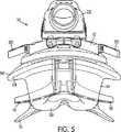
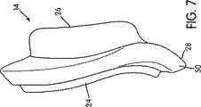
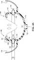
クッション(14)の中間部分(28)は、ガセット部分(50)を備えている。このガセット部分(50)は、顔面非接触部分(24)および顔面接触部分(26)に対して、径方向外向きに延出されている。ガセット部分(50)は、顔面接触部分(26)をガセット部分(50)に対して移動させることができる。さらに、ガセット部分(50)は顔面接触部分(26)と比較して、より大きな投影面積を有している(例えば、図10は、ガセット部分(50)が患者の顔面に重ねられた様子を示しており、これにより、ガセット部分(50)によって追加的にもたらされた面積を図示している)。ガセット部分(50)の付加的な投影面積は、患者の顔面上に接触力をもたらし、メンブラン(40)を介して、シールストリップ(68)(図10B)上に作用する。これにより、後述するように、クッション(14)のシール効率を増大させる。 The intermediate part (28) of the cushion (14) comprises a gusset part (50). The gusset portion (50) extends radially outward with respect to the non-face contact portion (24) and the face contact portion (26). The gusset portion (50) can move the face contact portion (26) relative to the gusset portion (50). Further, the gusset portion (50) has a larger projected area compared to the face contact portion (26) (eg, FIG. 10 shows the gusset portion (50) overlaid on the patient's face. And this illustrates the area additionally provided by the gusset portion (50)). The additional projected area of the gusset portion (50) provides a contact force on the patient's face and acts on the sealing strip (68) (FIG. 10B) via the membrane (40). This increases the sealing efficiency of the cushion (14), as will be described later.
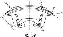
図6、6C、15に示すように、ガセット部分(50)は、顔面接触部分(26)の側壁(36)から外向きに延出されており、顔面非接触部分(24)のフランジ(32)の中へと内向きに湾曲している。特に、ガセット部分(50)は、顔面接触部分(26)の側壁(36)から外向きに延出されている第1側壁(52)と;顔面非接触部分(24)のフランジ(32)から外向きに延出されている第2側壁(54)と;これら第1および第2側壁(52,54)を相互に連結するアーチ形状壁(56)と;を備えている。ガセット部分(50)の壁(52,54,56)は、これらの間にスペース(57)を形成する。したがって、ガセット部分(50)は、平面視において、患者の顔面の輪郭に適合するように曲げられる。図39に示すように、例えば、ガセット部分は、80〜120mmという範囲の、好ましくは95〜105mmという範囲の、曲率半径を有している。 As shown in FIGS. 6, 6C and 15, the gusset portion (50) extends outwardly from the side wall (36) of the face contact portion (26) and the flange (32) of the face non-contact portion (24). ) Curved inward. In particular, the gusset portion (50) extends from the side wall (36) of the face contact portion (26) outwardly from the first side wall (52); from the flange (32) of the face non-contact portion (24). A second side wall (54) extending outwardly; and an arched wall (56) interconnecting the first and second side walls (52, 54). The walls (52, 54, 56) of the gusset portion (50) form a space (57) between them. Thus, the gusset portion (50) is bent to fit the contour of the patient's face in plan view. As shown in FIG. 39, for example, the gusset portion has a radius of curvature in the range of 80 to 120 mm, preferably in the range of 95 to 105 mm.
ガセット部分(50)は、内方エッジ(58)と、外方エッジ(60)と、を備えている。内方エッジ(58)は、側壁(36)の外方エッジに対応し、また、外方エッジ(60)は、ガセット部分(50)のアーチ形状壁(56)の頂点に対応する。図6および図10に示すように、内方エッジ(58)と外方エッジ(60)との間には、垂直距離(d)が形成される。この距離(d)は、患者の顔面上においてクッション(14)によって印加された圧力を変更し得るよう、変更することができる。図10Bに示すように、外方エッジ(60)と、顔面上におけるクッション接触ライン(61)と、の間の垂直距離として、距離(d2 )が定義される。接触ライン(61)は、シール形成部分(68)の外周縁である。すなわち、クッション(14)のシールストリップである。接触ライン(61)と外方エッジ(60)との間の追加面積は、メンブラン(40)に対して付加的な力をもたらす。患者の顔面上への接触力は、マスクキャビティ内における圧力と、ガセット部分(50)の投影面積と、に比例する。したがって、ガセット部分(50)の付加的面積は、例えば距離(d)を変えることにより、変更することができる。これにより、患者の顔面に対して印加される接触力を変更することができる。The gusset portion (50) includes an inner edge (58) and an outer edge (60). The inner edge (58) corresponds to the outer edge of the side wall (36) and the outer edge (60) corresponds to the apex of the arched wall (56) of the gusset portion (50). As shown in FIGS. 6 and 10, a vertical distance (d) is formed between the inner edge (58) and the outer edge (60). This distance (d) can be changed to change the pressure applied by the cushion (14) on the patient's face. As shown in FIG. 10B, the distance (d2 ) is defined as the vertical distance between the outer edge (60) and the cushion contact line (61) on the face. The contact line (61) is the outer peripheral edge of the seal forming part (68). That is, the seal strip of the cushion (14). The additional area between the contact line (61) and the outer edge (60) provides additional force on the membrane (40). The contact force on the patient's face is proportional to the pressure in the mask cavity and the projected area of the gusset portion (50). Thus, the additional area of the gusset portion (50) can be changed, for example, by changing the distance (d). Thereby, the contact force applied with respect to a patient's face can be changed.
本発明の一見地は、接触力を、患者の顔面上にわたって制御可能に分散させるということである。圧力および力は、クッションによるシールを維持しつつ、分散されるべきである。患者の顔面の敏感な領域に沿った局所的な圧力ポイントの形成を避けることが望ましい。例えば、局所的に接触力が集中したポイントは、鼻のブリッジ領域においては避けるべきである。これにより、患者に対する快適性を増大させることができる。 One aspect of the present invention is that the contact force is controllably distributed over the patient's face. Pressure and force should be distributed while maintaining a cushioned seal. It is desirable to avoid the formation of local pressure points along sensitive areas of the patient's face. For example, points where the contact force is concentrated locally should be avoided in the nasal bridge region. Thereby, the comfort with respect to a patient can be increased.
本発明の他の見地は、クッションによるシールを維持しつつ接触力を再分散され得るだけでなく、目の周囲におけるガセット面積を再成形することにより患者の視界を最適化することもできる。例えば、図12Cに示すように、ガセット部分(50)は、目の周囲において切欠部分(51)を備えており、これにより、患者の視界を改善することができる。 Another aspect of the invention is that not only can the contact force be redistributed while maintaining a cushion seal, but the patient's field of view can be optimized by reshaping the gusset area around the eye. For example, as shown in FIG. 12C, the gusset portion (50) includes a cutout portion (51) around the eye, which can improve the patient's field of view.
患者の顔面に対して印加された接触力がガセット部分(50)の投影面積に比例することにより、ガセット部分(50)の様々な場所において距離(d)を変更することにより、患者の顔面の異なる領域に対して印加される力を変更することができる。例えば、図12は、2つの可能な外方エッジを有したガセット部分(50)を示している。実線で示されている第1外方エッジ(60)においては、内方エッジ(58)と外方エッジ(60)との間における距離(d)が、ほぼ一定である。対照的に、破線で示されている第2外方エッジ(260)は、頬領域と比較して、唇領域および鼻のブリッジ領域において、より小さな距離(d’)を有している。 By varying the distance (d) at various locations on the gusset portion (50), the contact force applied to the patient's face is proportional to the projected area of the gusset portion (50). The force applied to the different areas can be changed. For example, FIG. 12 shows a gusset portion (50) with two possible outer edges. In the first outer edge (60) indicated by the solid line, the distance (d) between the inner edge (58) and the outer edge (60) is substantially constant. In contrast, the second outer edge (260), shown in dashed lines, has a smaller distance (d ') in the lip region and the nasal bridge region compared to the cheek region.
ガセット部分(50)は、顔面の選択された領域だけに設けることができ、その他の領域には設けないことができる。クッションの全周縁に沿って設ける必要はない。例えば、ガセット部分(50)は、唇部分だけに沿って設けることができる。 The gusset portion (50) can be provided only in a selected area of the face, and can not be provided in other areas. It is not necessary to provide along the entire periphery of the cushion. For example, the gusset portion (50) can be provided along only the lip portion.
したがって、破線で示されている第2外方エッジ(260)を有したガセット部分(50)は、実線で示された第1外方エッジ(60)を有したガセット部分(50)と比較して、患者の顔面の鼻ブリッジ領域および唇領域に対して、より小さな接触力を印加する。このようにして、患者の顔面に対して印加される接触力は、患者の顔面の敏感な領域からは遠ざかるように再分散することができる。例えば、鼻のブリッジ領域および唇領域からは遠ざかるように再分散することができる。そして、患者の顔面のより鈍感な領域に対して印加することができる。例えば、頬領域に対して印加することができる。患者の顔面の鼻のブリッジ領域が特に敏感であることにより、鼻ブリッジ領域(42)における面積が低減されているようなガセット部分(50)は、患者にとって、より快適なものとなる。しかしながら、距離(d)は、ガセット部分(50)の任意の領域に合わせて調整することができる。これにより、患者の顔面の各領域に対して印加される力を調整することができ、最大の快適性を与えることができる。これは、理想的な力とクッション回りの特別注文面積との双方を得るための特別注文に基づいて行うことができる。 Accordingly, the gusset portion (50) having the second outer edge (260) shown by the dashed line is compared with the gusset portion (50) having the first outer edge (60) shown by the solid line. Thus, a smaller contact force is applied to the nasal bridge region and the lip region of the patient's face. In this way, the contact force applied to the patient's face can be redistributed away from sensitive areas of the patient's face. For example, it can be redistributed away from the bridge and lip areas of the nose. It can then be applied to a less sensitive area of the patient's face. For example, it can be applied to the cheek region. The particularly sensitive nasal bridge area of the patient's face makes the gusset portion (50) such that the area in the nasal bridge area (42) is reduced more comfortable for the patient. However, the distance (d) can be adjusted to any region of the gusset portion (50). Thereby, the force applied with respect to each area | region of a patient's face can be adjusted, and maximum comfort can be given. This can be done based on a special order to obtain both an ideal force and a special order area around the cushion.
図12Bは、2つの可能な外方エッジを有したガセット部分(50)の他の実施形態を示している。実線で示されている第1外方エッジ(60)は、頬領域と比較して、唇領域および鼻ブリッジ領域において、外方エッジ(260)と内方エッジ(図示せず)との間の距離が、より小さなものとされている。対照的に、破線で示されている第2外方エッジ(260)は、外方エッジ(60)と内方エッジとの間において、ほぼ一定の距離を有している。 FIG. 12B shows another embodiment of a gusset portion (50) with two possible outer edges. The first outer edge (60), shown in solid lines, is between the outer edge (260) and the inner edge (not shown) in the lip region and the nasal bridge region compared to the cheek region. The distance is supposed to be smaller. In contrast, the second outer edge (260), shown in dashed lines, has a substantially constant distance between the outer edge (60) and the inner edge.
患者の顔面上の接触ラインに対して印加される接触力は、図6、6C、13A〜13Cに示されているように、ガセット部分のアーチ形状壁(56)の厚さを調節することにより、さらに調整することができる。アーチ形状壁(56)は、スプリング構造として作用し、メンブラン(40)を介して患者の顔面上へと接触力の一成分を提供する。アーチ形状壁(56’)は、一様な壁厚さを有したものとすることができる。あるいは、図13Aに示すように、薄い断面を有したものとすることができる。あるいは、アーチ形状壁(56”)は、図13Bに示すように、厚い断面を有したものとことができる。より薄いアーチ形状壁(56’)は、より厚いアーチ形状壁(56”)と比較して、より小さな力成分を提供する。アーチ形状壁(56,56’,56”)の断面積は、ガセット部分(50)の周囲回りにおいて場所ごとに異なるものとすることができる。例えば、ガセット部分は、患者の鼻のブリッジ領域においては、薄い壁のアーチ形状壁を有し、なおかつ、患者の頬領域においては、より厚い壁のアーチ形状壁を有することができる。さらに、アーチ形状壁は、距離(d)の変更に伴って変更することができる。例えば、距離(d)を低減させ、かつ、アーチ形状壁の厚さを増大させることができる。 The contact force applied to the contact line on the patient's face can be adjusted by adjusting the thickness of the arched wall (56) of the gusset portion, as shown in FIGS. 6, 6C, 13A-13C. Can be further adjusted. The arched wall (56) acts as a spring structure and provides a component of contact force through the membrane (40) onto the patient's face. The arcuate wall (56 ') may have a uniform wall thickness. Alternatively, as shown in FIG. 13A, it may have a thin cross section. Alternatively, the arched wall (56 ") can have a thick cross-section, as shown in Figure 13B. The thinner arched wall (56 ') is the thicker arched wall (56") and In comparison, it provides a smaller force component. The cross-sectional area of the arched wall (56, 56 ', 56 ") may vary from place to place around the circumference of the gusset portion (50). For example, the gusset portion may be Can have a thin-walled arch-shaped wall and, in the patient's cheek region, can have a thicker-walled arch-shaped wall. For example, the distance (d) can be reduced and the thickness of the arched wall can be increased.
これに代えて、ガセット部分(50)の全体を、テーパー形状とすることができる。ただし、アーチ形状壁の形状は、そのままとされる。 Alternatively, the entire gusset portion (50) can be tapered. However, the shape of the arch-shaped wall is left as it is.
患者の顔面上の接触ラインに対して印加される接触力は、ガセット部分(50)のところに図13Cに示すような内部係止構造(59)の設置することにより、さらに調整することができる。このような係止構造(59)のサイズや形状や幾何学的形態は、ガセット部分(50)の様々な領域において硬さを変更し得るように構成することができる。例えば、鼻のブリッジ領域においては、あまり硬くないものとし、かつ、頬領域においては、より硬いものとすることで、要求された快適性と、要求されたシールレベルと、を提供することができる。 The contact force applied to the contact line on the patient's face can be further adjusted by installing an internal locking structure (59) as shown in FIG. 13C at the gusset portion (50). . The size, shape and geometric form of such a locking structure (59) can be configured such that the hardness can be changed in various regions of the gusset portion (50). For example, it may be less stiff in the nasal bridge region and stiffer in the cheek region to provide the required comfort and the required seal level. .
他の態様においては、患者の顔面上の接触ラインに対して印加される接触力は、ガセット部分(50)にスプリング(例えば、スチールスプリング)を挿入することにより、調整することができる。このスプリングは、スプリングによって印加される力の成分を調節し得るよう構成されているようなばね定数を備えている。 In other aspects, the contact force applied to the contact line on the patient's face can be adjusted by inserting a spring (eg, a steel spring) into the gusset portion (50). The spring has a spring constant that is configured to adjust the component of the force applied by the spring.
これらの手法により、顔面の接触ライン上の接触力は、マスク圧力だけの関数ではなく、例えば、ガセット部分(50)内のスプリング部材の関数ともなる。これは、圧力の不安定さを改善し、高圧でのシール圧力を低減し、ガセット部分の視覚的なインパクトを低減する。 With these techniques, the contact force on the face contact line is not only a function of the mask pressure, but also a function of, for example, a spring member in the gusset portion (50). This improves pressure instability, reduces the sealing pressure at high pressure, and reduces the visual impact of the gusset portion.
図示の実施形態においては、ガセット部分(50)と、クッション(14)の顔面非接触部分(24)および顔面接触部分(26)とは、全体的に三角形状とされている。しかしながら、ガセット部分(50)と、クッション(14)の顔面非接触部分(24)および顔面接触部分(26)とは、任意の適切な形状のものとすることができる。例えば、三角形状以外の形状のものとすることができる。さらに、ガセット部分(50)と顔面非接触部分(24)と顔面接触部分(26)との形状は、互いに同様のものとすることができる、あるいは、互いに異なるものとすることができる。例えば、ガセット部分を、三角形状とし、なおかつ、顔面非接触部分および顔面接触部分を、全体的に台形形状とすることができる。 In the illustrated embodiment, the gusset portion (50) and the non-face contact portion (24) and face contact portion (26) of the cushion (14) are generally triangular. However, the gusset portion (50) and the non-face contact portion (24) and face contact portion (26) of the cushion (14) can be of any suitable shape. For example, it can be a shape other than a triangular shape. Furthermore, the shapes of the gusset portion (50), the non-face contact portion (24), and the face contact portion (26) can be the same as each other or different from each other. For example, the gusset portion can be triangular, and the face non-contact portion and face contact portion can be entirely trapezoidal.
クッション(14)は、例えばシリコーンといったようなソフトでありかつフレキシブルな皮膚適合性材料から形成される。クッション(14)は、当該技術分野において公知なように、例えば、1回の射出成形プロセスで形成することができる。しかしながら、クッション(14)は、任意の適切な材料が形成することができ、任意の適切なプロセスによって形成することができる。例えば、クッション(14)の顔面接触部分(26)は、よりソフトなグレードの材料から形成することができ、ガセット部分は、スプリング部材としての硬さを提供し得るよう、より硬いグレードの材料から形成することができる。顔面非接触部分(24)は、より硬いグレードの材料から形成することができる。このため、クッションクリップを使用することなくフレームに対する直接的な組立を可能とすることができる。 The cushion (14) is formed from a soft and flexible skin compatible material such as silicone. The cushion (14) can be formed, for example, in a single injection molding process, as is known in the art. However, the cushion (14) can be formed of any suitable material and can be formed by any suitable process. For example, the face contact portion (26) of the cushion (14) can be formed from a softer grade material and the gusset portion can be from a harder grade material so that it can provide stiffness as a spring member. Can be formed. The non-face contact portion (24) can be formed from a harder grade material. For this reason, the direct assembly with respect to a flame | frame can be enabled, without using a cushion clip.
クッション(14)は、従来技術におけるクッションと比較して、改善されたシールの安定性および快適性を提供する。特に、クッション(14)の湾曲度合いは、マスクアセンブリの安定性を全体的に改善する。また、ガセット部分は、シールの安定性を改善する。患者の顔面の様々な場所においてガセット部分の距離(d,d2 )を変更することにより、患者快適性レベルを改良することができる。The cushion (14) provides improved seal stability and comfort compared to cushions in the prior art. In particular, the degree of curvature of the cushion (14) improves the overall stability of the mask assembly. The gusset portion also improves the stability of the seal. By changing the distance (d, d2 ) of the gusset portion at various locations on the patient's face, the patient comfort level can be improved.
図14〜図33は、クッション(14)の様々な断面を示している。これら様々な断面は、患者の顔面の様々な領域において、リムとメンブランとの間の距離が様々なものとされていることを図示している。さらに、様々な断面は、患者の顔面の様々な領域において、ガセット部分(50)が様々な構成とされていることおよびガセット部分(50)の距離(d)が様々なものとされていることを、図示している。 14-33 show various cross sections of the cushion (14). These various cross-sections illustrate the various distances between the rim and the membrane in various regions of the patient's face. In addition, the various cross-sections have various configurations of the gusset portion (50) and various distances (d) of the gusset portion (50) in various regions of the patient's face. Is illustrated.
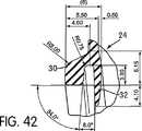
図34〜図42は、クッション(14)の一実施形態に関する構造的詳細および様々な寸法を示している。例えば、クッション(14)は、42〜62mmという範囲の長さを有しており、好ましくは52mmという長さを有しており、90〜110mmという範囲の高さを有しており、好ましくは100.5mmという高さを有しており、95〜115mmという範囲の幅を有しており、好ましくは103.2mmという幅を有している。クッション(14)の一実施形態においては、図34〜図42の中で図示された寸法は、±62%あるいは100%にわたって変更することができる。 Figures 34-42 show structural details and various dimensions for one embodiment of the cushion (14). For example, the cushion (14) has a length in the range of 42-62 mm, preferably has a length of 52 mm, and has a height in the range of 90-110 mm, preferably It has a height of 100.5 mm, a width in the range of 95 to 115 mm, and preferably a width of 103.2 mm. In one embodiment of the cushion (14), the dimensions illustrated in FIGS. 34-42 can vary over ± 62% or 100%.
図6Bは、本発明の代替可能な実施形態を示しており、この実施形態においては、ガセット部分(50)と、クッション(14)の顔面接触部分(26)と、の間に、補強リング(64)を備えている。1つの態様においては、補強リング(64)は、シリコーンの肉厚ビードから形成され、クッション(14)に対して成型される。補強リング(64)は、補強フープとして機能し、クッション(14)が圧力ポイントのところで膨張する傾向を低減させる。他の態様においては、補強リング(64)は、ポリカーボネートで作られており、オーバーモールドされるかあるいは押込係合される。 FIG. 6B shows an alternative embodiment of the present invention in which a reinforcement ring (between the gusset portion (50) and the face contact portion (26) of the cushion (14) is shown. 64). In one embodiment, the reinforcing ring (64) is formed from a thick silicone bead and molded to the cushion (14). The reinforcement ring (64) functions as a reinforcement hoop and reduces the tendency of the cushion (14) to expand at the pressure point. In other embodiments, the reinforcing ring (64) is made of polycarbonate and is overmolded or indented.
クッション(14)の顔面接触部分(26)は、0°〜360°にわたる値をとって角度位置を表す少なくとも1つのパラメータ(p)の関数によって規定され得るような表面を備えている。鼻に関しては、0°という位置は、鼻のブリッジの中央として定義することができ、鼻の隔壁は、180°という角度で現れることとなる。図15〜図22および図24〜図33は、様々な角度位置での一連の断面を示しており、すなわち、パラメータ(p)の様々な値を示している。 The face contact portion (26) of the cushion (14) is provided with a surface that can be defined by a function of at least one parameter (p) that takes values ranging from 0 ° to 360 ° and represents the angular position. With respect to the nose, the 0 ° position can be defined as the center of the nasal bridge, and the nasal septum will appear at an angle of 180 °. FIGS. 15-22 and 24-33 show a series of cross-sections at various angular positions, i.e. various values of the parameter (p).
マスクアセンブリ(10)の利点は、接触ストリップによって作用する接触力を調節することができ、これにより、過度に大きな高マスク圧力ではなく低マスク圧力でもって、許容可能なシールを提供することができるということである。例えば、スプリング構造を有していないガセット部分を備えたマスクアセンブリにおいては、接触力は、低マスク圧力においては、小さすぎるものであり、そのため、シールをもたらすためにはガセット面積を増大させなければならない。この付加的なガセット面積は、高マスク圧力をもたらして、接触力を過度に大きなものとしてしまう。ガセット部分に対してスプリング構造を組み合わせることは、低いマスク圧力であっても、ガセット部分をを大きく必要なく、接触力を、スプリング構造によって、もたらし得ることを意味している。高マスク圧力においては、ガセット部分によってもたらされる接触力は、スプリング構造によってもたらされる接触力と比較して、はるかに大きなものとすることができる。したがって、マスクアセンブリ(10)は、様々な圧力範囲にわたって、マスクシステムの接触力を調整することができる。 An advantage of the mask assembly (10) is that the contact force exerted by the contact strip can be adjusted, thereby providing an acceptable seal with a low mask pressure rather than an excessively high mask pressure. That's what it means. For example, in a mask assembly with a gusset portion that does not have a spring structure, the contact force is too small at low mask pressures, so the gusset area must be increased to provide a seal. Don't be. This additional gusset area results in high mask pressure and excessive contact force. Combining the spring structure with the gusset portion means that even with a low mask pressure, a large gusset portion is not required and contact force can be provided by the spring structure. At high mask pressure, the contact force provided by the gusset portion can be much greater compared to the contact force provided by the spring structure. Thus, the mask assembly (10) can adjust the contact force of the mask system over various pressure ranges.
本発明の他の態様においては、ヘッドギアの伸張可能性が、変更可能とされている。例えば、比較的伸張不可能なヘッドギアを、低マスク圧力において使用することができる。一方、より伸張可能なヘッドギアを、例えば20cmH2O といったような高マスク圧力において使用することができる。1つの態様においては、これは、ヘッドギア内において二重のストラップを備えることにより、達成される。その場合、一方のストラップは、拡張可能なものとされ、他方のストラップは、比較的拡張不可能なものとされる。低圧においては、両方のストラップが使用される。正味の効果は、ヘッドギアが、比較的拡張不可能なものであることである。高圧においては、拡張不可能なストラップの係合が解除され、その結果、ヘッドギアは、全体的に比較的拡張性のものとなる。In another aspect of the present invention, the expandability of the headgear can be changed. For example, relatively inextensible headgear can be used at low mask pressures. On the other hand, more extensible headgear can be used at high mask pressures, such as20 cmH2 O. In one aspect, this is accomplished by providing double straps in the headgear. In that case, one strap is expandable and the other strap is relatively unexpandable. At low pressure, both straps are used. The net effect is that the headgear is relatively unexpandable. At high pressure, the non-expandable strap is disengaged so that the headgear is generally relatively expandable.
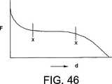
図43は、例えば膨張といったような固定的延出状態で保持された少なくとも1つのガセット部分を備えたマスクマスクに関し、患者の顔面上の接触力を示している。x軸は、マスク内部の圧力である。y軸は、患者の顔面上における接触力である。快適性とシールとが両立している領域(Z)は、以下によって定義される。(a)4〜20cmH2O という典型的な動作圧力範囲。(b)患者の顔面上におけるシールを維持するために必要とされる最小の接触力。この接触力は、マスク内部圧力の増加関数として定義される。(c)快適な接触力の最大値。FIG. 43 shows the contact force on the patient's face for a mask mask with at least one gusset portion held in a fixed extension such as, for example, inflated. The x axis is the pressure inside the mask. The y-axis is the contact force on the patient's face. The region (Z) where comfort and sealing are compatible is defined by: (A) typical operating pressure range of 4~20cmH2 O. (B) The minimum contact force required to maintain a seal on the patient's face. This contact force is defined as an increasing function of the mask internal pressure. (C) Maximum value of comfortable contact force.
本発明の一実施形態においては、クッションは、ガセット部分およびスプリング構造を備えて構成されており、クッションによって印加される接触力が、快適性とシールとが両立している領域(Z)内に維持する。 In one embodiment of the present invention, the cushion includes a gusset portion and a spring structure, and the contact force applied by the cushion is within a region (Z) in which comfort and sealing are compatible. maintain.
図43は、少なくとも1つのガセット部分を備えた3つ仮想的クッションに関する3つのラインを示している。一般に、第1近似においては、接触力は、ガセット部分によってもたらされた付加的投影面積の結果として、マスク圧力につれて直線的に増大する。 FIG. 43 shows three lines for three virtual cushions with at least one gusset portion. In general, in the first approximation, the contact force increases linearly with mask pressure as a result of the additional projected area provided by the gusset portion.
第1ライン(L1)は、A1という付加的投影面積を有しておりかつスプリング構造を有していないガセット部分を備えたクッションを、表している。図示のように、接触力は、約7cmH2O よりもマスク圧力が小さい場合には、シールを形成するのに必要な最小の接触力を下回っている。ライン(L1)によって表わされるクッションは、快適性とシールとが両立している領域(Z)の外部となる。より高い圧力(例えば、約7cmH2O よりも大きなマスク圧力)については、ガセット部分からの接触力が、シールを維持するのに十分である。The first line (L1) represents a cushion with a gusset portion having an additional projected area of A1 and not having a spring structure. As shown, the contact force is below the minimum contact force required to form a seal when the mask pressure is less than about 7 cmH2 O. The cushion represented by the line (L1) is outside the region (Z) where comfort and seal are compatible. For higher pressures (eg, a mask pressure greater than about 7 cmH2 O), the contact force from the gusset portion is sufficient to maintain the seal.
第2ライン(L2)は、A1という付加的投影面積を有しかつスプリング構造を有しているガセット部分を備えた、本発明の一実施形態に基づくクッションを表している。スプリング構造の効果は、ガセット部分の効果では最小のシール力を提供するのに不十分な場合に、低いマスク圧力で、付加的な接触力を提供することである。その結果、クッションは、動作圧力範囲にわたってシールを維持する。さらに、ライン(L2)によって表されたクッションは、動作圧力の全体にわたって、快適性とシールとが両立している領域(Z)に位置している。 The second line (L2) represents a cushion according to an embodiment of the invention with a gusset portion having an additional projected area of A1 and having a spring structure. The effect of the spring structure is to provide an additional contact force at a low mask pressure when the effect of the gusset portion is insufficient to provide a minimum sealing force. As a result, the cushion maintains a seal over the operating pressure range. Furthermore, the cushion represented by the line (L2) is located in the region (Z) where comfort and sealing are compatible throughout the operating pressure.
第3のライン(L3)は、A1の2倍という付加的投影面積を有しておりかつスプリング構造を有していないガセット部分を備えたクッションを、表している。過剰の投影面積(L1とL2によって表されているクッションの2倍)のために、クッションの接触力が、4cmH2O という低いマスク圧力においてシールを維持するのに十分なものとなる。しかしながら、約10cmH2O よりも大きなマスク圧力に関しては、接触力は、快適な接触力の最大値を超えている。したがって、ライン(L3)によって表されるクッションは、快適性とシールとが両立している領域(Z)の外側となる。The third line (L3) represents a cushion with a gusset portion that has an additional projected area of twice A1 and does not have a spring structure. Due to the excess projected area (twice the cushion represented by L1 and L2), the contact force of the cushion is sufficient to maintain the seal at a mask pressure as low as 4 cmH2 O. However, for mask pressures greater than about 10 cmH2 O, the contact force exceeds the maximum comfortable contact force. Therefore, the cushion represented by the line (L3) is outside the region (Z) where comfort and seal are compatible.
したがって、クッション内において、ガセット部分にスプリング構造を組み合わせることにより、製造者は、すべての動作圧力範囲内にわたって快適性とシールとが両立している領域(Z)の内部に位置しているようにして、クッションの接触力を調整することができる。同じ原理は、異なる圧力範囲に対しても適用することができる。 Therefore, by combining the gusset portion with a spring structure within the cushion, the manufacturer is positioned within the zone (Z) where comfort and seal are compatible over the entire operating pressure range. Thus, the contact force of the cushion can be adjusted. The same principle can be applied to different pressure ranges.
さらに、領域(Z)のサイズは、患者の顔面の特定の領域に依存して、変わり得るものである(例えば、快適な接触力の最大値が変わることによって)。例えば、快適な接触力の最大値は、顔面の鼻のブリッジ領域においては、低減することとなる。その結果、クッションは、そのような特定部位に関しては、動作圧力の全体にわたって快適性とシールとが両立している領域(Z)の内部に位置するように、調節することができる。 Furthermore, the size of region (Z) can vary depending on the particular region of the patient's face (eg, by changing the maximum comfortable contact force). For example, the maximum value of the comfortable contact force is reduced in the bridge region of the nose of the face. As a result, the cushion can be adjusted to be located within such a region (Z) where both comfort and seal are compatible over the entire operating pressure for such specific sites.
図44は、一定のマスク圧力において、患者の顔面に対して印加された合計力に関してのスプリング構造の効果を示している。Fmaskは、国際公開第01/97893号パンフレット(Frater氏他)において定義されるように、患者の顔面上におけるマスクの合計力である。マスクがガセット部分を備えていることにより、クッションの2つの側面は、互いに移動することができる。ガセット部分の拡張または膨張が0mmである場合、クッションの2つの側面は、互いに当接する。ガセット部分の拡張が50mmである場合、クッションの2つの側面は、50mm間隔となる。クッションの2つの側面が互いに接近すればするほど、Fmaskの値は、大きくなる。FIG. 44 shows the effect of the spring structure on the total force applied to the patient's face at a constant mask pressure. Fmask is the total force of the mask on the patient's face, as defined in WO 01/97893 (Frater et al.). The mask is provided with a gusset portion so that the two sides of the cushion can move relative to each other. When the expansion or expansion of the gusset portion is 0 mm, the two sides of the cushion abut each other. If the extension of the gusset portion is 50 mm, the two sides of the cushion will be 50 mm apart. The closer the two sides of the cushion are to each other, the greater the value of Fmask .
図44は、4個の異なるクッションを表わす4つのラインを示している。第1ライン(L1)は、スプリング構造を有しておらずかつA1という付加的投影面積を有したガセット部分を備えたクッションに関するものである。第2ライン(L2)は、スプリング構造を有しておりかつA1の62%という付加的投影面積を有したガセット部分を備えた本発明の一実施形態によるクッションに関するものである。第3ライン(L3)は、スプリング構造を有しておらずかつA1の85%という付加的投影面積を有したガセット部分を備えたクッションに関するものである。第4ライン(L4)は、スプリング構造を有しておらずかつA1の62%という付加的投影面積を有したガセット部分を備えたクッションに関するものである。 FIG. 44 shows four lines representing four different cushions. The first line (L1) relates to a cushion having a gusset portion that does not have a spring structure and has an additional projected area of A1. The second line (L2) relates to a cushion according to an embodiment of the invention with a gusset portion having a spring structure and an additional projected area of 62% of A1. The third line (L3) relates to a cushion having a gusset portion that does not have a spring structure and has an additional projected area of 85% of A1. The fourth line (L4) relates to a cushion with a gusset portion that does not have a spring structure and has an additional projected area of 62% of A1.
図示されているように、ガセット部分を備えているクッションに対してのスプリング構造の追加は、ガセット膨張の全範囲にわたってFmaskを増大させる。その結果、クッションは、シールを維持するための十分なFmaskをもたらすに際し、従来技術の場合よりも、より小さな投影面積を有したガセット部分を備えたものとして、構成することができる。As shown, the addition of a spring structure to a cushion with a gusset portion increases Fmask over the full range of gusset expansion. As a result, the cushion can be configured with a gusset portion having a smaller projected area than in the prior art in providing sufficient Fmask to maintain the seal.
さらに、Fmaskに対するスプリングの効果は、様々なマスク圧力に関して決定することができる。これにより、クッションは、患者の顔面の特定の領域に応じて調節することができる。Further, the effect of the spring on Fmask can be determined for various mask pressures. This allows the cushion to be adjusted according to the specific area of the patient's face.
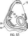
『弾性カフ』
図45〜49は、上述のまたは後述の実施形態と組み合わせて使用し得るような、本発明の代替可能な実施形態を示している。図45に示すように、マスクアセンブリ(100)は、マスクフレーム(112)と、クッション(114)と、ストラップ(116)と、を備えている。それらのすべては、上述した実施形態と同様にして組み立てられる。"Elastic cuff"
FIGS. 45-49 illustrate alternative embodiments of the present invention that may be used in combination with the embodiments described above or below. As shown in FIG. 45, the mask assembly (100) includes a mask frame (112), a cushion (114), and a strap (116). All of them are assembled in the same manner as the embodiment described above.
フレームは、加圧状態とされたエアまたは呼吸可能ガスの供給源と連通している入口(122)を備えている。好ましくは、入口は、旋回可能なエルボーに対して連結され、このエルボーは、エア供給チューブに対して連結される。 The frame includes an inlet (122) in communication with a source of pressurized air or breathable gas. Preferably, the inlet is connected to a pivotable elbow that is connected to an air supply tube.
上述したように、クッション(114)は、マスクフレーム(112)に設けられた顔面非接触部分(124)を備えている。クッション(114)は、さらに、顔面接触部分(126)と、顔面非接触部分(124)および顔面接触部分(126)の間に位置した中間部分(128)と、を備えている。上述したように、顔面接触部分(126)は、メンブラン(140)とリム(138)とを有してなる顔面接触シール形成部分(168)を備えている。 As described above, the cushion (114) includes the face non-contact portion (124) provided on the mask frame (112). The cushion (114) further includes a face contact portion (126) and an intermediate portion (128) positioned between the face non-contact portion (124) and the face contact portion (126). As described above, the face contact portion (126) includes a face contact seal forming portion (168) comprising a membrane (140) and a rim (138).
中間部分(128)には、弾性的に膨張可能とし得る少なくとも1つのカフ(170)を設けることができる。カフ(170)は、単にフレキシブルであるのとは違って弾性的に引き伸ばし得るような壁を有している。ストラップ(116)が締め付けられるにつれて、メンブラン(140)とリム(138)とが、顔面に対して押し付けられる。この操作により、メンブラン(140)とリム(138)と顔面接触部分(126)とに対して力が印加され、顔面接触部分(126)は、顔面非接触部分(124)の方向に変位することとなる。顔面接触部分(126)および関連する力の変位によって、カフ(170)が外向きに膨張する。力は、ストラップの締め付け度合いと、カフ(170)の硬さ(力と変位との相関関係)と、カフ(170)の初期的膨張は、バルブ(175)を介して得ることができる。バルブ(175)は、マスクアセンブリ(100)の呼吸チャンバ(171)に対して加圧エアを供給するのと同じ供給源に対して接続することができる、あるいは、呼吸チャンバ(171)に対して加圧状態の呼吸可能ガスを供給するための供給源とは個別の供給源に対して接続することができる。弾性カフ(170)は、クッション(114)と一緒に単一部材として形成することができる。これに代えて、弾性カフ(170)は、クッション(114)とは個別部材として形成することができ、その後、例えば接着剤や機械的固定部材や類似物等を使用して、取り付けることができる。 The intermediate portion (128) may be provided with at least one cuff (170) that may be elastically inflatable. The cuff (170) has a wall that can be elastically stretched rather than simply flexible. As the strap (116) is tightened, the membrane (140) and rim (138) are pressed against the face. By this operation, force is applied to the membrane (140), the rim (138), and the face contact portion (126), and the face contact portion (126) is displaced in the direction of the face non-contact portion (124). It becomes. The displacement of the face contact portion (126) and associated force causes the cuff (170) to expand outward. The force can be obtained via the valve (175), the degree of tightening of the strap, the hardness of the cuff (170) (correlation between force and displacement), and the initial expansion of the cuff (170). The valve (175) can be connected to the same source that supplies pressurized air to the breathing chamber (171) of the mask assembly (100) or to the breathing chamber (171). A source for supplying pressurized breathable gas can be connected to a separate source. The elastic cuff (170) can be formed as a single piece with the cushion (114). Alternatively, the elastic cuff (170) can be formed as a separate member from the cushion (114) and then attached using, for example, an adhesive, a mechanical fastening member, or the like. .
現在のマスクシステムにおいては、比較的大きな弾性率を有した材料から形成されて比較的硬い膨張可能なカフを使用している。これに対し、本発明の各実施形態によるカフ(170)は、比較的小さな硬さを有するように構成されている。これは、例えば、比較的小さな力であっても引き伸ばされ得る壁を有したカフ(170)を使用することによって、達成される。この特性を備えた壁は、典型的には、比較的小さな弾性係数を有した材料から形成される。例えば、弾性カフをなす材料の弾性係数は、ベンチ試験によって測定した場合、0.15MPa〜0.6MPaという範囲にある。弾性係数の好ましい値は、0.25MPa〜0.45MPaという範囲である。一例においては、弾性係数は、約0.35MPaである。比較すれば、上述のガセット部分は、0.40MPa〜0.80MPaという弾性係数を有している。好ましくは、約0.60MPaという弾性係数を有している。ガセットおよび弾性カフ(170)の双方に関する弾性係数は、上述した値とすることができる、あるいは、供給されたマスク圧力やヘッドギアの張力やストラップの変位に関連した適切な伸張特性をもたらし得るように修正することができる。 Current mask systems use a relatively stiff, inflatable cuff formed from a material having a relatively large modulus of elasticity. On the other hand, the cuff (170) according to each embodiment of the present invention is configured to have a relatively small hardness. This is accomplished, for example, by using a cuff (170) with a wall that can be stretched even with relatively little force. Walls with this property are typically formed from materials having a relatively small elastic modulus. For example, the elastic modulus of the material forming the elastic cuff is in the range of 0.15 MPa to 0.6 MPa when measured by a bench test. A preferable value of the elastic modulus is in a range of 0.25 MPa to 0.45 MPa. In one example, the elastic modulus is about 0.35 MPa. In comparison, the above-described gusset portion has an elastic coefficient of 0.40 MPa to 0.80 MPa. Preferably, it has an elastic modulus of about 0.60 MPa. The modulus of elasticity for both the gusset and the elastic cuff (170) can be the values described above, or can provide suitable stretch characteristics related to the supplied mask pressure, headgear tension and strap displacement. It can be corrected.
上記各実施形態においては、例えば図1に関しては、マスクシステムと、ガセット付きのクッションとは、多くの利点をもたらす。例えば、フレームが少々不安定であっても、クッションシールを維持することができ、また、シール維持のために顔面に向けてクッション圧力を印加するのに必要なヘッドギアストラップに関して必要な位置調整が少々ずれていたにしても、クッションシールを維持することができる。図45に示すような弾性カフ(170)を有したクッションは、また、上記各実施形態と同様の結果を示す。しかしながら、弾性カフによる力は、流体供給源からの供給エアとは、独立的である。 In each of the above embodiments, for example with respect to FIG. 1, the mask system and the gusseted cushion provide many advantages. For example, even if the frame is a little unstable, the cushion seal can be maintained, and the necessary positional adjustment with respect to the headgear strap required to apply the cushion pressure toward the face to maintain the seal. Even if it is displaced, the cushion seal can be maintained. A cushion having an elastic cuff (170) as shown in FIG. 45 also shows the same results as in the above embodiments. However, the force due to the elastic cuff is independent of the supply air from the fluid supply.
従来技術におけるマスクは、膨張可能な(verses elastic)カフや、気圧シールや、シールリング、を使用している。これら膨張可能なカフは、典型的には、PVCから形成されている。PVCは、比較的大きな弾性係数を有していて、比較的硬いものである。PVC材料に対するベンチ試験により、弾性係数が約5.2MPaであることがわかった。PVCは、ある程度のフレキシブルさを有してはいるものの、図45に示されている弾性カフ(170)のようには、弾性的に膨張可能なものではない。比較的大きな弾性係数を有した膨張可能なカフの例は、Toffolon氏による米国特許第4,971,051号明細書に開示されているとともに、King Systems社により麻酔用マスクとして入手可能である。 Prior art masks use verses elastic cuffs, barometric seals and seal rings. These inflatable cuffs are typically formed from PVC. PVC has a relatively large elastic modulus and is relatively hard. Bench tests on PVC material revealed an elastic modulus of about 5.2 MPa. Although PVC has some flexibility, it is not elastically inflatable like the elastic cuff (170) shown in FIG. An example of an inflatable cuff having a relatively large modulus of elasticity is disclosed in US Pat. No. 4,971,051 by Toffolon and is available as an anesthetic mask by King Systems.
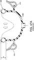
1)図46は、ガセットを有した上記実施形態(ResMed社のActiva(登録商標)マスク)に関しての、力と位置ズレ(硬さ)との関係を示すグラフであり;2)図47は、従来技術に関しての、力と位置ズレ(硬さ)との関係を示すグラフであり;3)図48は、図45に示す弾性カフに関しての、力と位置ズレ(硬さ)との関係を示すグラフである。記号‘d’で示された横軸は、図45(上述)および図47Aにおける寸法‘d’を表していることに、注意されたい。図47Aは、ストラップ(310)および膨張可能カフ(320)を備えた従来技術によるマスクフレーム(300)を示している。図46に示すように、Activa(登録商標)マスクの場合の平坦領域は、マスクシステムに対して、顔面に対するクッションシールによる比較的一定な押圧力を維持するに際しての、ストラップ張力とマスク不安定性とに関するより大きな許容範囲を、もたらす。図46におけるポイントX−X間のラインを参照されたい。 1) FIG. 46 is a graph showing the relationship between force and misregistration (hardness) for the above embodiment with Resset (Activa® mask from ResMed) with gussets; 2) FIG. FIG. 48 is a graph showing the relationship between force and displacement (hardness) with respect to the prior art; 3) FIG. 48 shows the relationship between force and displacement (hardness) with respect to the elastic cuff shown in FIG. It is a graph. Note that the horizontal axis indicated by the symbol 'd' represents the dimension 'd' in FIG. 45 (above) and FIG. 47A. FIG. 47A shows a prior art mask frame (300) with a strap (310) and an inflatable cuff (320). As shown in FIG. 46, the flat area in the case of an Activa® mask shows the strap tension and mask instability in maintaining a relatively constant pressing force against the mask system by the cushion seal against the face. Results in greater tolerance. See the line between points XX in FIG.
対照的に、図47のグラフは、比較的大きな弾性係数を有した材料から形成されている従来技術における膨張可能カフが、力と位置ズレとの特性がより線形であって、より硬いことを、示している。したがって、顔面に対してのマスクまたはクッションのわずかの変化であっても、すなわち、寸法‘d’がわずかに変化しただけであっても、顔面に対して印加されるシール力は、比較的大きく変化することとなる。したがって、この従来技術によるマスクシステムは、位置ズレが大きい場合には(不安定性のために)、良好なシールを維持することができない。ストラップの張力は、快適性に関する許容可能レベルを維持するのに批判的である。 In contrast, the graph of FIG. 47 shows that the inflatable cuff in the prior art, formed from a material with a relatively large modulus of elasticity, has a more linear force and displacement characteristic and is stiffer. Show. Therefore, even if there is a slight change of the mask or cushion to the face, i.e., the dimension 'd' is only slightly changed, the sealing force applied to the face is relatively large. Will change. Thus, this prior art mask system cannot maintain a good seal if the misalignment is large (due to instability). Strap tension is critical to maintaining an acceptable level of comfort.
したがって、この実施形態の1つの見地は、伸縮性のあるバルーンのように、弾力係数が比較的小さい材料から弾性カフを形成することである。弾性カフ材料は、この用途において経験する標準的なストラップ張力の下で、伸張能力を有している。 Thus, one aspect of this embodiment is to form the elastic cuff from a material with a relatively low coefficient of elasticity, such as a stretchable balloon. The elastic cuff material has the ability to stretch under the standard strap tension experienced in this application.
マスクが適合していない状態では、膨張可能なカフは、必ずしも圧力を印加する必要はない。適正に適合した状態では、カフは、ストラップが締め付けられるほどに、圧縮される。弾性カフ材料の小さな弾性係数が与えられたときには、カフは、図45において仮想線で示すように、カフが引き伸ばされるにつれて、伸張し得るようにまた膨らみ得るように膨れ得るようにまた膨出し得るように構成されている。 In an incompatible state, the inflatable cuff does not necessarily need to apply pressure. In a properly fitted condition, the cuff is compressed as the strap is tightened. Given the small modulus of elasticity of the elastic cuff material, the cuff can also bulge so that it can expand and expand as the cuff is stretched, as shown in phantom in FIG. It is configured as follows.
クッションシールに対して印加される力は、カフ壁の硬さを調節することにより、微調整することができる。例えば、弾性係数を増減させることにより、微調整することができる。あるいは、この例においてはバルブを介することにより弾性カフ(170)を事前に加圧しておくことにより、クッションが位置ズレしたりあるいは適合したりあるいはストラップの張力が増大されたときには、クッションによるシール力を増大させる。 The force applied to the cushion seal can be finely adjusted by adjusting the hardness of the cuff wall. For example, fine adjustment can be made by increasing or decreasing the elastic modulus. Alternatively, in this example, when the elastic cuff (170) is pre-pressurized by way of a valve, when the cushion is misaligned or fits or the strap tension is increased, the sealing force of the cushion Increase.
図48に示すように、弾性カフ(170)は、図46に示されている平坦ラインと同様の平坦ラインを生成し得るような小さな弾性係数を有した材料から形成される。しかしながら、このグラフは、図46と比較すると、わずかに傾斜している。それでもなお、図47のグラフよりは、平坦性が大きい。理想は、図46と図48の中間の平坦角度を有していることである。 As shown in FIG. 48, the elastic cuff (170) is formed from a material with a small modulus of elasticity that can produce a flat line similar to the flat line shown in FIG. However, this graph is slightly inclined as compared to FIG. Nevertheless, the flatness is greater than the graph of FIG. The ideal is to have a flat angle intermediate between FIG. 46 and FIG.
より大きな弾性係数を有した材料から形成されたような、より硬いカフは、図48に示されているグラフと比較して、より右下がりの傾斜が大きくなるであろう。従来技術における膨張可能なカフの場合には、比較的非常に高い硬さが、ごくわずかの位置ズレに対しても、クッションによるシール力の非常に大きな変化をもたらす。このことは、顔面のシールの損失となり得る。わずかの位置ズレをもたらす原因には、例えば、ストラップの張力を変化させてしまうような夜行性の動作や、ヒトの顔面の流体の減少や、下顎の弛緩、等がある。 A stiffer cuff, such as formed from a material with a higher modulus of elasticity, will have a greater slope to the right as compared to the graph shown in FIG. In the case of inflatable cuffs in the prior art, the relatively very high hardness leads to a very large change in the sealing force by the cushion, even for a very small misalignment. This can result in a loss of facial seal. The causes of slight positional deviation include, for example, nocturnal movement that changes the tension of the strap, reduction of human facial fluid, relaxation of the lower jaw, and the like.
さらなる実施形態においては、弾性カフ(170)は、任意の圧縮可能流体によって、あるいは、任意の非圧縮性流体によって、あるいは、それらのある種の組合せによって、充填することができる。流体は、例えば、エアや、流動性の液体や、流動性または半流動性のゲル、とすることができる。エアの場合には、張力状態のカフ壁は、カフ内部のエアを圧縮し、クッションシールを顔面に向けて外へと向かせる。気体であることのために、エアにはいくらかの圧縮性がある。液体で充填されている場合には、クッションシール上のすべての力は、圧縮性ガスの影響なしで、カフ壁の張力だけによって作用する。 In further embodiments, the elastic cuff (170) can be filled by any compressible fluid, by any incompressible fluid, or by some combination thereof. The fluid can be, for example, air, a fluid liquid, or a fluid or semi-fluid gel. In the case of air, the tensioned cuff wall compresses the air inside the cuff and causes the cushion seal to face outwards toward the face. Due to being a gas, air has some compressibility. When filled with a liquid, all forces on the cushion seal are only exerted by the cuff wall tension, without the influence of compressible gas.
クッションの振舞いの変化は、弾性係数や、弾性カフの幾何形状や、材料選択(例えば、弾性係数の選択)や、初期的流体重量(取付前の流体重量)、のいずれによっても、また、それらの組合せによっても、達成することができる。 Changes in the behavior of the cushion depend on the elastic modulus, elastic cuff geometry, material selection (e.g., elastic modulus selection), and initial fluid weight (fluid weight prior to installation). This can also be achieved by a combination of the above.
流体の初期的重量は、バルブによって、手動であるいは自動的に、調節することができる(カフ圧力および/またはCPAP治療圧力に関連する外部と内部との間の制御も含めて)。図45においては、弾性カフが、クッションアセンブリから離間していることがわかる。すなわち、クッションのうちの、顔面に接触してシールをもたらす部分から離間していることがわかる。したがって、変位可能量が最小とされ、弾性的でも弾力的でもない、単なるフレキシブルな気圧式シールがもたらされる。 The initial weight of the fluid can be adjusted manually or automatically by a valve (including external and internal controls related to cuff pressure and / or CPAP treatment pressure). In FIG. 45, it can be seen that the elastic cuff is spaced from the cushion assembly. That is, it can be seen that the cushion is separated from the portion that comes into contact with the face and brings about a seal. Thus, a mere flexible pneumatic seal is provided which has a minimum amount of displacement and is neither elastic nor elastic.
図45においては、膨張可能な/収縮性の弾性カフ(170)は、クッションシールに組み込まれる。 In FIG. 45, an inflatable / shrinkable elastic cuff (170) is incorporated into the cushion seal.
他の実施形態においては、弾性カフは、手動ポンプ(180)を使用して加圧することができる。これにより、弾性カフ(170)内の流体の初期的重量を微調整することができる。例えば、図49を参照されたい。 In other embodiments, the elastic cuff can be pressurized using a manual pump (180). Thereby, the initial weight of the fluid in the elastic cuff (170) can be finely adjusted. For example, see FIG.
他の実施形態においては、供給された処理圧力に対して同期させ得るようにしておよび/またはリークに応答させ得るようにしておよび/または不快さの検出に応答させ得るようにして、カフの流体重量を自動的に制御することができる。 In other embodiments, the cuff fluid can be synchronized to the supplied process pressure and / or can be responsive to leaks and / or can be responsive to detection of discomfort. The weight can be controlled automatically.
チャンバあるいは弾性カフ(170)の形成に際しては、任意の弾性材料を使用することができる。ラテックス製バルーンの使用は、使用可能な材料の1つである。また、小さなデュロメーター硬さおよび/または小さな弾性係数を有したシリコーンゴムを、使用することもできる。あるいは、それらの組合せを使用することもできる。カフは、構造的一体性を提供し得るよう、剛直なまたは半剛直な細部を有することができる。 Any elastic material can be used in forming the chamber or elastic cuff (170). The use of latex balloons is one material that can be used. Silicone rubber having a small durometer hardness and / or a small elastic modulus can also be used. Alternatively, combinations thereof can be used. The cuff can have rigid or semi-rigid details so as to provide structural integrity.
カフ(170)は、周縁全体を囲む必要はない。例えば、鼻のブリッジの付近には、設けなくても良い。これにより、受領されるクッションシール力を修正することができる。本明細書において開示した弾性カフ(170)は、従来技術におけるマスクシステム内に組み込むことができあるいは従来技術によるマスクシステムと一緒に使用することができ、これにより、新規な改良された製品を形成することができる。例えば、Respironics 社は、“Profile Lite”(登録商標)ゲルクッションを製造した。このクッションは、弾性カフ(170)を組み込むことができる。この場合、弾性カフは、一体的に形成することも、また、フレームとシールインターフェースとの間に取り付けることも、できる。弾性カフは、例えばエアやゲルやあるいはこれらの任意の組合せといったような圧縮性のまたは非圧縮性の流体によって充填することができる。 The cuff (170) need not surround the entire periphery. For example, it may not be provided near the bridge of the nose. Thereby, the received cushion seal force can be corrected. The elastic cuff (170) disclosed herein can be incorporated into a mask system in the prior art or can be used with a mask system according to the prior art, thereby forming a new and improved product. can do. For example, Respironics manufactured "Profile Lite" (R) gel cushion. The cushion can incorporate an elastic cuff (170). In this case, the elastic cuff can be integrally formed or can be attached between the frame and the seal interface. The elastic cuff can be filled with a compressible or incompressible fluid, such as air, gel, or any combination thereof.
他の例においては、弾性カフ(170)は、Toffolon氏による米国特許第4,971,051号明細書に開示されている見地と組み合わせることができる。弾性カフは、クッションアセンブリの一部として組み込むことができる。これにより、クッションシール内に力をもたらし得るとともに、マスクフレームに対してのクッションシールの移動/変位に対して独立的なものとすることができる。 In another example, the elastic cuff (170) can be combined with the aspect disclosed in US Pat. No. 4,971,051 by Toffolon. The elastic cuff can be incorporated as part of the cushion assembly. This can provide a force within the cushion seal and can be independent of movement / displacement of the cushion seal relative to the mask frame.
鼻用マスクが、好ましい実施形態として例示されているけれども、本発明の原理は、フルフェイス型のマスクや口マスクに対しても、適用することができる。さらに、本発明の原理は、鼻孔の近くをシールする非常に狭いシール領域を有した鼻用マスクに対しても、適用することができる。 Although a nasal mask is illustrated as a preferred embodiment, the principles of the present invention can also be applied to full face masks and mouth masks. Furthermore, the principles of the present invention can be applied to nasal masks having a very narrow sealing area that seals near the nostril.
『ブーメラン』シール
図50〜図56は、最初の実施形態と一緒に使用可能であるような本発明の他の実施形態を示している。図50は、フルフェイス型の呼吸用マスク(10)を示す斜視図であって、着用者の頭に固定した状態で図示されている。マスク(10)は、クッション(14)を支持するフレーム(12)を備えている。マスク(10)は、ヘッドギアによって、着用者の鼻と口との領域上に固定されている。ヘッドギアは、着用者の頭回りにおいて調節可能とされた固定用ストラップ(16)を備えている。“Boomerang” Seal FIGS. 50-56 show another embodiment of the invention that can be used with the first embodiment. FIG. 50 is a perspective view showing the full-face type respiratory mask (10), which is fixed to the wearer's head. The mask (10) includes a frame (12) that supports the cushion (14). The mask (10) is fixed on the wearer's nose and mouth area by headgear. The headgear includes a fixing strap (16) that is adjustable around the wearer's head.
フレーム(12)は、好ましくは、サドルの態様とされているとともに、着用者の鼻上において適合し得るようあるいは少なくとも着用者の鼻孔上において適合し得るよう、全体的に三角形形状または台形形状とされている。フレーム(12)は、口の両サイドから顎に向けて下向きに延在している。フレーム(12)は、ポート(18)を備えている。このポート(18)は、旋回可能エルボーアセンブリ(22)を介して、呼吸可能ガスの供給源(20)に対して連結されている。ガス供給源(20)は、加圧ガスの供給源とすることができ、着用者の鼻および口を受領するマスク(10)内のチャンバに対して呼吸可能ガスを供給する。 The frame (12) is preferably in the form of a saddle and has a generally triangular or trapezoidal shape so that it can fit on the wearer's nose or at least fit on the wearer's nostril. Has been. The frame (12) extends downward from both sides of the mouth toward the chin. The frame (12) has a port (18). This port (18) is connected via a swivel elbow assembly (22) to a breathable gas source (20). The gas source (20) may be a source of pressurized gas and supplies breathable gas to a chamber in the mask (10) that receives the wearer's nose and mouth.
フレーム(12)は、さらに、ベント穴(24)を備えている。このベント穴(24)を通すことによって、吐出ガスが排出されるようになっている。ヘッドギアのストラップ(16)を固定するために、ファスナー(26)が設けられている。このファスナー(26)は、ヘッドギアの選択的な調節を可能としている。この場合、ファスナー(26)は、フレーム(12)に形成されたスロットとされ、このスロット内に、ストラップ(16)を適用するようになっている。当然のことながら、任意の適切なファスナーを使用することができる。所望によっては、額支持部材も併用することができる。額支持部材とは、額に向けて上向きに、フレームから延出される支持部材である。 The frame (12) further includes a vent hole (24). The discharged gas is discharged by passing through the vent hole (24). A fastener (26) is provided to secure the headgear strap (16). This fastener (26) allows selective adjustment of the headgear. In this case, the fastener (26) is a slot formed in the frame (12), and the strap (16) is applied in the slot. Of course, any suitable fastener can be used. If desired, a forehead support member may be used in combination. The forehead support member is a support member that extends upward from the frame toward the forehead.
フレーム(12)は、図51において、クッション(14)と合わせて示されている。呼吸用マスクの当業者であれば理解されるように、クッション(14)は、様々な手法によって、フレーム(12)上のフランジ(28)に対して固定することができる。クッション(14)は、フランジ(28)と一体的に形成することができる。あるいは、クッション(14)は、フランジ(28)に対して取り付けることができる。あるいは、クッション(14)は、フランジ(28)に対して着脱可能にクリップ止めすることができる。他の取付手法としては、ストラップ止めや、摩擦係合や、干渉係合や、タング・グルーブ係合、を使用することができる。 The frame (12) is shown together with the cushion (14) in FIG. As will be appreciated by those skilled in the respirator art, the cushion (14) can be secured to the flange (28) on the frame (12) by a variety of techniques. The cushion (14) can be formed integrally with the flange (28). Alternatively, the cushion (14) can be attached to the flange (28). Alternatively, the cushion (14) can be detachably clipped to the flange (28). As other attachment methods, strap fastening, friction engagement, interference engagement, tongue / groove engagement can be used.
図52においては、クッション(14)は、フレーム(12)から取り外されており、図51を背面側から見た図となっており、クッション(14)の顔面接触部分を図示している。クッション(14)は、フレーム(12)に対する連結のためのフランジ(30)と;フレーム(12)の内部チャンバに対する開口(34)を規定する内周リム(32)と;フランジ(30)と内周リム(32)との間に配置されたシール部分(36)と;を備えている。 In FIG. 52, the cushion (14) is removed from the frame (12), and is a view of FIG. 51 viewed from the back side, and illustrates a face contact portion of the cushion (14). The cushion (14) includes a flange (30) for connection to the frame (12); an inner peripheral rim (32) defining an opening (34) to the internal chamber of the frame (12); And a sealing portion (36) disposed between the circumferential rim (32).
好ましくは、クッション(14)は、例えばシリコーンといったようなソフトでありかつフレキシブルな皮膚適合性材料から形成される。適切な1つの材料は、Dow Corning 社によって製造されたシリコンエラストマーであるSILASTIC(登録商標)である。クッションは、例えば、当該技術分野において公知なように、1回の射出成形プロセスで形成することができる。クッション(14)をなす様々な部分は、様々な厚さで、あるいは様々な材料からさえも、形成することができる。これにより、例えば、硬さと弾性とに影響を及ぼすことができる。また、クッション(14)を、全体的にあるいは部分的に、発泡体材料またはゲル材料から形成することも、想定される。クッション(14)は、上記のプロセスおよび材料の組合せに基づいて形成することができる。 Preferably, the cushion (14) is formed from a soft and flexible skin compatible material such as silicone. One suitable material is SILASTIC®, a silicone elastomer manufactured by Dow Corning. The cushion can be formed, for example, in a single injection molding process, as is known in the art. The various parts forming the cushion (14) can be formed with various thicknesses or even from various materials. Thereby, for example, hardness and elasticity can be affected. It is also envisaged that the cushion (14) is formed entirely or partly from a foam material or a gel material. The cushion (14) can be formed based on a combination of the processes and materials described above.
内周リム(32)およびシール部分(36)は、図56において、最も明瞭に示されている。図56は、シール部分(36)がゆっくりと湾曲した形状を有しており、これにより、内周リム(32)を超えて延在しているリップを形成していることを示している。好ましくは、シール部分(36)は、内周リム(32)と比較して、よりフレキシブルなものとしてあるいはより薄いものとして形成される。これにより、着用者の顔面の輪郭に対して、より容易に適合することができる。シール部分(36)は、ソフトなシールを提供する。このソフトなシールは、着用者の顔面の形状における少しの変化を許容することができるとともに、有効なシールを維持しつつ、着用者に対してのマスクの少しの移動を可能とすることができる。マスク(10)に対して供給された固定力に応じて、クッション(14)は、内周リム(32)に対して当接するようになるまで、変形することができる。フランジ(30)は、フルフェイス型のクッション(14)の使用時における通常的な固定圧力に耐え得るよう十分な剛直さを有しており、その形状を維持する傾向があり、かつ、変形に対する抵抗性を有している。これにより、フランジ(30)は、支持構造として、機能する。 Inner rim (32) and seal portion (36) are most clearly shown in FIG. FIG. 56 shows that the seal portion (36) has a slowly curved shape, thereby forming a lip that extends beyond the inner rim (32). Preferably, the sealing portion (36) is formed as being more flexible or thinner than the inner peripheral rim (32). Thereby, it can adapt to the outline of a wearer's face more easily. The seal portion (36) provides a soft seal. This soft seal can tolerate slight changes in the shape of the wearer's face and can allow a slight movement of the mask relative to the wearer while maintaining an effective seal. . Depending on the fixing force supplied to the mask (10), the cushion (14) can be deformed until it comes into contact with the inner peripheral rim (32). The flange (30) has sufficient rigidity to withstand the normal fixing pressure when using the full face type cushion (14), tends to maintain its shape, and is resistant to deformation. Has resistance. Thereby, a flange (30) functions as a support structure.
ここに示す実施形態は、単一の内周リム(32)と単一のシール部分(36)とを備えている。これにより、二重壁構成を形成している。クッション(14)は、また、単一壁構成や、三重壁構成や、さらなる多重壁構成、とすることができる。さらに、内周リム(32)およびシール部分(36)は、互いに異なる材料から形成することができる。 The embodiment shown here comprises a single inner rim (32) and a single sealing part (36). This forms a double wall configuration. The cushion (14) can also be in a single wall configuration, a triple wall configuration, or a further multiple wall configuration. Further, the inner rim (32) and the seal portion (36) can be formed from different materials.
所望であれば、シール部分(36)は、顔面の湾曲度合いに追従するようにしてゆっくりと湾曲した拡大部分であるガセット部分を備えることができる。 If desired, the seal portion (36) can include a gusset portion that is an enlarged portion that slowly curves to follow the degree of curvature of the face.
シール部分(36)は、着用者の顔面と接触し得るよう構成されているとともに、なおかつ、着用者の顔面に対してシールを形成し得るよう構成されている。これにより、フレーム(12)の内部チャンバに供給されたガスは、マスク(10)の外部へとリークすることはない。シール部分(36)は、鼻領域(38)を備えている。この鼻領域(38)は、鼻領域にわたって広がっており、鼻のブリッジを横切って着用者の鼻孔上に延在しており、図52〜図54に示すように、全体的に逆V字形状とされている。鼻領域(38)の両サイドににおいては、側面領域(40)が、着用者の口の両サイドの外側まで下向きに延出されており、全体的に逆V字形状を継続している。顎領域(42)が、側面領域(40)どうしの間にわたって延在している。これについては、詳細に後述する。 The seal portion (36) is configured to contact the wearer's face and is configured to form a seal against the wearer's face. Thereby, the gas supplied to the internal chamber of the frame (12) does not leak to the outside of the mask (10). The seal part (36) comprises a nasal region (38). This nose region (38) extends across the nose region and extends across the nose bridge over the wearer's nostril and is generally inverted V-shaped as shown in FIGS. It is said that. On both sides of the nose region (38), the side region (40) extends downward to the outside of both sides of the wearer's mouth, and continues in an inverted V shape as a whole. A jaw region (42) extends between the side regions (40). This will be described in detail later.
平面視または底面視においては、クッション(14)の形状は、図55に示すように、鼻端部および顎端部において1つの中央凹部と、頬部分において1つの凸部と、を備えている。これにより、着用者の顔面に適合することができる。すなわち、着用者の顔面に対して垂直な平面内においては、クッション(14)は、鼻および顎が突出しているというヒトの顔面の輪郭に追従し得るように、湾曲している。これは、呼吸用マスクの分野においては、公知である。 In the plan view or the bottom view, the shape of the cushion (14) includes one central concave portion at the nose end portion and the chin end portion and one convex portion at the cheek portion as shown in FIG. . Thereby, it can adapt to a wearer's face. That is, in a plane perpendicular to the wearer's face, the cushion (14) is curved so that it can follow the contour of the human face that the nose and chin protrude. This is well known in the field of respiratory masks.
図53および図54に示すように、クッション(14)の顎領域(42)は、正面視および背面視において、従来技術による呼吸用マスクにはないような形状を有している。上述したように、従来技術によるマスクにおいては、クッションの顎領域は、着用者の顔面と全体的に平行な平面内において、直線状であるかあるいはU字形状である。従来技術における着想は、口の周辺において顎領域に対して緊密に適合させることである。しかしながら、本発明のこの実施形態においては、顎領域(42)は、そうではなく、顎の骨の輪郭に対して緊密に適合し得るような形状とされている。この領域における特徴的骨格は、オトガイ隆起と顎上の下歯との間にあり、眉間の皺に似たような、下向きに湾曲したかつ外向き湾曲した骨ラインを形成している。したがって、クッション(14)は、ブーメランあるいは逆U字形状のような形状とされた顎領域(42)を備えている。顎領域(42)は、下唇とオトガイ隆起との間に適合し得るように構成されている。図54に示すように、シール形状は、W字形状を示すことができる。逆U字形状またはW形状をなすすべての部分は、着用者に適合し得るように形状を調節することができる。例えば、シール部分は、延展性を有したワイヤから形成することができる。これにより、ワイヤを曲げることによって、そのような調節可能性をもたらすことができ、着用者の顔面の輪郭に対してシール部分を適合させることができる。このような上向きに湾曲した形状すなわちアーチ形状は、図51〜図54に示されている。背面視においては、アーチ形状を有することができる。一方、正面視および/または側面視においては、フルフェイス型マスクの現在の形状を維持することができる。 As shown in FIGS. 53 and 54, the jaw region (42) of the cushion (14) has a shape that is not found in a conventional respiratory mask in front view and rear view. As mentioned above, in the mask according to the prior art, the jaw region of the cushion is linear or U-shaped in a plane generally parallel to the wearer's face. The idea in the prior art is to closely fit the jaw area around the mouth. However, in this embodiment of the invention, the jaw region (42) is instead shaped to be able to closely fit the jaw bone contour. The characteristic skeleton in this region is between the chin ridge and the lower teeth on the jaw, forming a downwardly curved and outwardly curved bone line, similar to the eyebrows. Accordingly, the cushion (14) includes a jaw region (42) shaped like a boomerang or an inverted U shape. The jaw region (42) is configured to fit between the lower lip and the chin ridge. As shown in FIG. 54, the seal shape can indicate a W-shape. All parts that form an inverted U-shape or W-shape can be adjusted to fit the wearer. For example, the seal portion can be formed from a wire that is malleable. This can provide such adjustability by bending the wire and can adapt the seal portion to the contour of the wearer's face. Such an upwardly curved shape, that is, an arch shape is shown in FIGS. In the rear view, it can have an arch shape. On the other hand, in the front view and / or the side view, the current shape of the full-face mask can be maintained.
この形状により、側面領域(40)は、下顎に向けてさらに下方へと延出することができる。所望であれば、クッション(14)は、より安定的な支持をもたらし得るよう、下顎にまで延出したようなサイズとことができる。これによって、クッション(14)は、顔面のうちの、形状が変化しにくいような骨領域上に適合し、下唇や頬のような、よりソフトでありかつ脂肪的な領域と比較して、シールを向上させる。 This shape allows the side region (40) to extend further downward toward the lower jaw. If desired, the cushion (14) can be sized to extend to the lower jaw to provide more stable support. This allows the cushion (14) to fit over a bone area of the face that is less likely to change shape, as compared to softer and fatty areas such as the lower lip and cheeks, Improve the seal.
治療時に、圧力が着用者に対して印加されたときには、フレキシブルであるような唇は、わずかに強制的に開口させられる。よって、下唇は、外向きに移動しかつわずかに下向きに移動する。下唇がこのように移動したときには、アーチ形状クッション(14)に対しての緊密な接触が形成され、シール性能がさらに向上する。また、所望によっては、口を通してのリークを低減することができる。 During treatment, when pressure is applied to the wearer, the lips that are flexible are forced to open slightly. Thus, the lower lip moves outward and slightly downwards. When the lower lip moves in this way, intimate contact with the arched cushion (14) is formed, further improving the sealing performance. Further, if desired, leakage through the mouth can be reduced.
クッション(14)およびマスク(10)を、CPAPあるいは呼吸支援治療に関して説明したけれども、本発明が、ガスおよび/または霧化液体を気道入口に対して供給するような任意の用途に関して適用可能であることは、理解されるであろう。そのような用途には、噴霧器や、ガスマスクや、麻酔機械、がある。加えて、マスクは、口のみをカバーするような口だけのマスクに対しても、適用することができる。また、クッションは、顎を超えてさらに下方へと延出させることができ、これにより、クッションをさらに安定性させることができる。 Although the cushion (14) and mask (10) have been described with respect to CPAP or respiratory support therapy, the present invention is applicable for any application such as supplying gas and / or atomized liquid to the airway inlet. That will be understood. Such applications include nebulizers, gas masks and anesthesia machines. In addition, the mask can also be applied to a mouth-only mask that covers only the mouth. In addition, the cushion can be extended further downward beyond the jaw, thereby further stabilizing the cushion.
以上により、本発明の様々な見地が、完全にかつ効果的に達成されることは、理解されるであろう。上記のいくつかの特定の実施形態は、本発明のフレーム的原理および機能的原理を例示するためのものであって、本発明を何ら制限することを意図したものではない。それとは逆に、本発明においては、本発明の精神および範囲を逸脱していないすべての修正や変形や代替をも包含することが意図されている。 From the foregoing, it will be appreciated that the various aspects of the invention are achieved completely and effectively. Some specific embodiments described above are intended to exemplify the frame principle and the functional principle of the present invention, and are not intended to limit the present invention in any way. On the contrary, the present invention is intended to cover all modifications, variations, and alternatives that do not depart from the spirit and scope of the present invention.
10 呼吸用マスクアセンブリ
12 フレーム
14 クッション
24 顔面非接触部分
26 顔面接触部分
28 中間部分
32 フランジ
36 側壁
38 リム
40 メンブラン
42 鼻ブリッジ領域
44 頬領域
46 唇領域
50 ガセット部分
51 切欠部分(凹所)
52 第1側壁
54 第2側壁
56 アーチ形状壁(スプリング構造)
58 内方エッジ
60 第1外方エッジ
68 シール形成部分
100 マスクアセンブリ
112 フレーム
114 クッション
124 顔面非接触部分
126 顔面接触部分
128 中間部分
138 リム
140 メンブラン
168 シール形成部分
170 弾性カフ
260 第2外方エッジDESCRIPTION OF
52
58
Claims (26)
Translated fromJapaneseフレームに対して連結された顔面非接触部分(24)と;
患者の顔面に対して係合し得るよう構成された顔面接触部分(26)と;
これら顔面非接触部分と顔面接触部分とを相互連結するための中間部分(28)であるとともに、前記顔面接触部分を介して患者の顔面に対して力の第1成分を印加し得るよう構成されたガセット部分(50)を備えているような、中間部分(28)と;
前記顔面接触部分に対して連結されたスプリング構造(56)であるとともに、前記顔面接触部分を介して患者の顔面に対して力の第2成分を印加し得るよう構成された、スプリング構造(56)と;
を具備し、
前記中間部分が印加する前記力の第1成分と、前記スプリング構造が印加する前記力の第2成分とが、前記顔面接触部分を介して患者の顔面に対して印加される接触力を決定するものとされ、
前記中間部分が、前記顔面非接触部分および前記顔面接触部分から離間するように径方向外向きに延在しており、これにより、前記クッションの接触ラインの外側に、付加的投影面積がもたらされており、
前記スプリング構造が、比較的低いマスク圧力をもたらす接触力を提供し得るよう構成され、
これにより、前記ガセット部分が、前記スプリング構造による接触力との組合せによって、比較的高いマスク圧力をもたらす接触力を提供し得るよう構成されていることを特徴とするクッション。A cushion (14) for a respiratory mask assembly for supplying breathable gas to a patient,
A non-facial face (24) connected to the frame;
A face contact portion (26) configured to engage the patient's face;
It is an intermediate portion (28) for interconnecting the non-face contact portion and the face contact portion, and is configured to be able to apply a first component of force to the patient's face via the face contact portion. An intermediate portion (28), such as comprising a gusseted portion (50);
A spring structure (56) coupled to the face contact portion and configured to apply a second component of force to the patient's face via the face contact portion. )When;
Comprising
The first component of the force applied by the intermediate portion and the second component of the force applied by the spring structure determine the contact force applied to the patient's face via the face contact portion. It is assumed
The intermediate portion extends radially outwardly away from the non-face contact portion and the face contact portion, thereby providing additional projected area outside the contact line of the cushion. Hasbeen
The spring structure is configured to provide a contact force that provides a relatively low mask pressure;
Accordingly, the cushionis configured such that the gusset portion can provide a contact force that provides a relatively high mask pressure in combination with the contact force by the spring structure .
患者の顔面に対して印加される前記接触力が、前記クッションの全周縁回りにおいて実質的に均等に分散されていることを特徴とするクッション。The cushion according to claim 1,
The cushion, wherein the contact force applied to the patient's face is distributed substantially evenly around the entire periphery of the cushion.
患者の顔面に対して印加される前記接触力が、鼻のブリッジ領域における方が、患者の顔面の頬領域と比較して、より小さなものとされていることを特徴とするクッション。The cushion according to claim 1,
The cushion according to claim 1, wherein the contact force applied to the patient's face is smaller in the bridge region of the nose than in the cheek region of the patient's face.
前記クッションによって患者の顔面に対して印加される前記接触力が、顔面の敏感な領域における方が、顔面の鈍感な領域と比較して、より小さなものとされていることを特徴とするクッション。The cushion according to claim 1,
The cushion, wherein the contact force applied to the patient's face by the cushion is smaller in the sensitive area of the face than in the insensitive area of the face.
前記ガセット部分が、前記顔面接触部分から径方向外向きに延在した第1側壁と、前記顔面非接触部分から径方向外向きに延在した第2側壁と、これら第1側壁および第2側壁を相互に連結するアーチ形状壁と、を備え、
前記ガセット部分の前記第1側壁と前記第2側壁と前記アーチ形状壁とが、前記付加的投影面積を規定していることを特徴とするクッション。The cushion according to claim 1,
The gusset portion includes a first side wall extending radially outward from the face contact portion, a second side wall extending radially outward from the non-face contact portion, and the first side wall and the second side wall. Arch-shaped walls that interconnect each other, and
The cushion, wherein the first side wall, the second side wall, and the arch-shaped wall of the gusset portion define the additional projected area.
前記ガセット部分の前記アーチ形状壁と、前記クッションの前記接触ラインと、の間の距離が、患者の顔面に対して印加される力の前記第1成分を少なくとも部分的に決定する寸法を、規定していることを特徴とするクッション。The cushion according to claim 5,
Defining a dimension such that the distance between the arched wall of the gusset portion and the contact line of the cushion at least partially determines the first component of the force applied to the patient's face; Cushion characterized by being.
前記アーチ形状壁が、前記スプリング構造として作用し、これにより、前記顔面接触部分を介して、患者の顔面に対して印加される力の前記第2成分をもたらしており、
前記アーチ形状壁の厚さによって、力の前記第2成分が調節可能とされていることを特徴とするクッション。The cushion according to claim 5,
The arched wall acts as the spring structure, thereby providing the second component of the force applied to the patient's face via the face contact portion;
The cushion, wherein the second component of the force is adjustable by the thickness of the arch-shaped wall.
前記ガセット部分が、前記ガセット部分の各領域ごとに異なるものとし得るような寸法を有し、これにより、患者の顔面に対して印加される力の前記第1成分を各領域ごとに調節し得るものとされていることを特徴とするクッション。The cushion according to claim 1,
The gusset portion has dimensions that can be different for each region of the gusset portion, thereby allowing the first component of the force applied to the patient's face to be adjusted for each region. Cushion characterized by being made.
前記顔面非接触部分が、前記フレームに対して着脱可能に連結されていることを特徴とするクッション。The cushion according to claim 1,
The cushion, wherein the face non-contact portion is detachably connected to the frame.
前記顔面非接触部分が、クッションクリップを使用することにより、前記フレームに対して着脱可能に連結されていることを特徴とするクッション。The cushion according to claim 9,
The cushion, wherein the face non-contact portion is detachably connected to the frame by using a cushion clip.
前記顔面接触部分が、側壁と、この側壁から離間する向きに延出されたリムと、このリムを実質的に囲み得るように構成されたメンブランと、を備えていることを特徴とするクッション。The cushion according to claim 1,
The cushion, wherein the face contact portion includes a side wall, a rim extending in a direction away from the side wall, and a membrane configured to substantially surround the rim.
前記クッションが、2つ以上のリムと、これら2つ以上のリムを実質的に囲み得るように構成されたメンブランと、を備えていることを特徴とするクッション。The cushion according to claim 11,
The cushion includes two or more rims and a membrane configured to substantially surround the two or more rims.
前記クッションが、1つのリムと、このリムを実質的に囲み得るように構成された2つ以上のメンブランと、を備えていることを特徴とするクッション。The cushion according to claim 11,
The cushion includes a rim and two or more membranes configured to substantially surround the rim.
前記顔面接触部分が、ゲル部分を備えていることを特徴とするクッション。The cushion according to claim 1,
The cushion, wherein the face contact part includes a gel part.
前記顔面接触部分が、全体的に三角形状を有していることを特徴とするクッション。The cushion according to claim 1,
The cushion, wherein the face contact portion has a generally triangular shape.
前記ガセット部分が、患者の顔面の輪郭に対して追従し得るよう、湾曲した形状を有していることを特徴とするクッション。The cushion according to claim 1,
The cushion, wherein the gusset portion has a curved shape so as to follow a contour of a patient's face.
前記顔面接触部分が、与えられたマスク圧力において、患者の顔面の様々な領域に対して互いに異なる接触力を印加し得るよう構成されていることを特徴とするクッション。The cushion according to claim 1,
The cushion, wherein the face contact portion is configured to apply different contact forces to various regions of a patient's face at a given mask pressure.
前記ガセット部分が、患者の視界に影響を及ぼさないように構成されていることを特徴とするクッション。The cushion according to claim 1,
The cushion characterized by the said gusset part being comprised so that a patient's visual field may not be affected.
前記ガセット部分が、患者の顔面の輪郭に対して追従し得るよう構成され、これにより、前記ガセット部分の高さを低減させていることを特徴とするクッション。The cushion according to claim 1,
A cushion characterized in that the gusset portion is configured to follow a contour of a patient's face, thereby reducing the height of the gusset portion.
前記ガセット部分が、凹所を有し、これにより、患者の視界に影響を及ぼさないように構成されていることを特徴とするクッション。The cushion according to claim 1,
The cushion is characterized in that the gusset portion has a recess so that it does not affect the patient's field of view.
前記スプリング構造が、前記ガセット部分内に配置された少なくとも1つのスプリングによってもたらされ、
この少なくとも1つのスプリングが、力の前記第2成分を調節し得るよう構成されたばね定数を有していることを特徴とするクッション。The cushion according to claim 1,
The spring structure is provided by at least one spring disposed in the gusset portion;
A cushion, wherein the at least one spring has a spring constant configured to adjust the second component of force.
前記ガセット部分が、患者の顔面に対して印加される力の前記第1成分を少なくとも部分的に決定する寸法を有していることを特徴とするクッション。The cushion according to claim 1,
A cushion, wherein the gusset portion has a dimension that at least partially determines the first component of the force applied to the patient's face.
前記少なくとも1つのスプリングと前記ガセット部分とが、それぞれ力の前記第2成分および前記第1成分を調節し得るよう構成され、これにより、患者の顔面の各領域に対して印加される前記接触力を調節し得るようになっているいることを特徴とするクッション。The cushion according to claim 1,
The at least one spring and the gusset portion are configured to adjust the second component and the first component, respectively, of the force, whereby the contact force applied to each region of the patient's face Cushion characterized by being able to adjust.
フレームと;
請求項1に記載されたクッションと;
を具備していることを特徴とする呼吸用マスクアセンブリ。A breathing mask assembly for supplying breathable gas to a patient, comprising:
Frame;
A cushion according to claim 1;
A respiratory mask assembly, comprising:
前記ガセット部分が、前記クッションの接触ラインの外側に、付加的投影面積をもたらし、
前記ガセット部分によって提供される接触力が、マスク圧力に比例するものとされていることを特徴とするクッション。The cushion according to claim1 ,
The gusset portion provides additional projected area outside the contact line of the cushion;
A cushion characterized in that the contact force provided by the gusset portion is proportional to the mask pressure.
前記スプリング構造が、ばね定数を有するものとされ、
前記スプリング構造によって印加される接触力が、前記ばね定数によって制御されるものとされていることを特徴とするクッション。The cushion according to claim1 ,
The spring structure has a spring constant;
The cushion, wherein the contact force applied by the spring structure is controlled by the spring constant.
Applications Claiming Priority (4)
| Application Number | Priority Date | Filing Date | Title |
|---|---|---|---|
| US10/235,846US6823869B2 (en) | 2001-09-07 | 2002-09-06 | Mask assembly |
| US42468602P | 2002-11-08 | 2002-11-08 | |
| US48362203P | 2003-07-01 | 2003-07-01 | |
| PCT/AU2003/001163WO2004022146A1 (en) | 2002-09-06 | 2003-09-05 | Cushion for a respiratory mask assembly |
Related Child Applications (1)
| Application Number | Title | Priority Date | Filing Date |
|---|---|---|---|
| JP2009140433ADivisionJP5107307B2 (en) | 2002-09-06 | 2009-06-11 | Cushion for breathing mask assembly |
Publications (2)
| Publication Number | Publication Date |
|---|---|
| JP2005537906A JP2005537906A (en) | 2005-12-15 |
| JP4570966B2true JP4570966B2 (en) | 2010-10-27 |
Family
ID=31982280
Family Applications (3)
| Application Number | Title | Priority Date | Filing Date |
|---|---|---|---|
| JP2004569779AExpired - Fee RelatedJP4570966B2 (en) | 2002-09-06 | 2003-09-05 | Cushion for breathing mask assembly |
| JP2009140433AExpired - Fee RelatedJP5107307B2 (en) | 2002-09-06 | 2009-06-11 | Cushion for breathing mask assembly |
| JP2010195597AExpired - Fee RelatedJP5864088B2 (en) | 2002-09-06 | 2010-09-01 | Cushion for breathing mask assembly |
Family Applications After (2)
| Application Number | Title | Priority Date | Filing Date |
|---|---|---|---|
| JP2009140433AExpired - Fee RelatedJP5107307B2 (en) | 2002-09-06 | 2009-06-11 | Cushion for breathing mask assembly |
| JP2010195597AExpired - Fee RelatedJP5864088B2 (en) | 2002-09-06 | 2010-09-01 | Cushion for breathing mask assembly |
Country Status (7)
| Country | Link |
|---|---|
| US (5) | US7523754B2 (en) |
| EP (2) | EP2913079B1 (en) |
| JP (3) | JP4570966B2 (en) |
| CN (2) | CN100592926C (en) |
| AU (1) | AU2003257274B2 (en) |
| NZ (1) | NZ573196A (en) |
| WO (1) | WO2004022146A1 (en) |
Families Citing this family (236)
| Publication number | Priority date | Publication date | Assignee | Title |
|---|---|---|---|---|
| AUPQ104099A0 (en)* | 1999-06-18 | 1999-07-08 | Resmed Limited | Forehead support for facial mask |
| DE20017940U1 (en) | 2000-10-19 | 2000-12-28 | MAP Medizintechnik für Arzt und Patient GmbH & Co KG, 82152 Planegg | Breathing mask for supplying a breathing gas to a mask user and a derivation device for deriving breathing gas |
| DE10201682A1 (en) | 2002-01-17 | 2003-07-31 | Map Medizin Technologie Gmbh | The breathing mask arrangement |
| DE10151984C5 (en) | 2001-10-22 | 2008-07-17 | Map Medizin-Technologie Gmbh | Application device for a breathing mask arrangement |
| US7320323B2 (en) | 2001-10-22 | 2008-01-22 | Map Medizin-Technologie Gmbh | Breathing mask device and application device and frontal support device thereof |
| US6892729B2 (en) | 2001-11-20 | 2005-05-17 | Fisher & Paykel Healthcare Limited | Patient interfaces |
| AU150091S (en) | 2002-01-17 | 2002-12-06 | Resmed R&D Germany Gmbh | Modular breathing mask |
| AU2003246441B2 (en)* | 2002-06-14 | 2009-01-22 | Resmed R&D Germany Gmbh | Mask cushioning and forehead pad for a respiratory mask, respiratory mask in addition to a mould and method for their production |
| WO2004007010A1 (en)* | 2002-07-12 | 2004-01-22 | Fisher & Paykel Healthcare Limited | Breathing assistance apparatus |
| ES2443417T3 (en) | 2002-09-06 | 2014-02-19 | Resmed Limited | Forehead pad for a respiratory mask |
| JP4570966B2 (en) | 2002-09-06 | 2010-10-27 | レスメド・リミテッド | Cushion for breathing mask assembly |
| AU2003275762A1 (en) | 2002-11-06 | 2004-06-07 | Resmed Limited | Mask and components thereof |
| USD556898S1 (en) | 2002-11-08 | 2007-12-04 | Resmed Limited | Portion of a mask |
| USD486227S1 (en) | 2002-11-08 | 2004-02-03 | Resmed Limited | Forehead pad assembly |
| USD545960S1 (en)* | 2002-11-08 | 2007-07-03 | Resmed Limited | Portion of a forehead pad assembly |
| USD567935S1 (en) | 2002-11-08 | 2008-04-29 | Resmed Limited | Portion of forehead pad |
| WO2004052438A1 (en) | 2002-12-06 | 2004-06-24 | Fisher & Paykel Healthcare Limited | Mouthpiece |
| US7318437B2 (en) | 2003-02-21 | 2008-01-15 | Resmed Limited | Nasal assembly |
| US7503327B2 (en)* | 2003-04-10 | 2009-03-17 | Resmed Limited | Mask with integral cushion and forehead piece |
| CN101987221B (en) | 2003-05-02 | 2013-09-04 | 雷斯梅德有限公司 | A mask system |
| USD567936S1 (en)* | 2003-05-05 | 2008-04-29 | Resmed Limited | Portion of a mask |
| US8714157B2 (en) | 2003-09-03 | 2014-05-06 | Fisher & Paykel Healthcare Limited | Mask |
| US9119929B2 (en) | 2003-12-08 | 2015-09-01 | Fisher & Paykel Healthcare Limited | Breathing assistance apparatus |
| EP2510968B1 (en)* | 2003-12-31 | 2017-02-08 | ResMed Limited | Compact oronasal patient interface |
| WO2005079726A1 (en) | 2004-02-23 | 2005-09-01 | Fisher & Paykel Healthcare Limited | Breathing assistance apparatus |
| US9072852B2 (en)* | 2004-04-02 | 2015-07-07 | Fisher & Paykel Healthcare Limited | Breathing assistance apparatus |
| EP3936180B1 (en) | 2004-04-02 | 2023-11-29 | Fisher & Paykel Healthcare Limited | Breathing assistance apparatus |
| CN101683545B (en)* | 2004-04-09 | 2012-11-28 | 雷斯梅德有限公司 | Nasal assembly and nasal face mask with the nasal assembly |
| US20070246043A1 (en) | 2004-04-15 | 2007-10-25 | Resmed Limited | Positive-Air-Pressure Machine Conduit |
| US8807135B2 (en) | 2004-06-03 | 2014-08-19 | Resmed Limited | Cushion for a patient interface |
| NZ608551A (en) | 2004-06-16 | 2014-10-31 | Resmed Ltd | Cushion for a respiratory mask assembly |
| US7845352B2 (en)* | 2004-07-20 | 2010-12-07 | Carefusion 205, Inc. | Flexible CPAP mask |
| USD584400S1 (en)* | 2004-07-29 | 2009-01-06 | Fisher & Paykel Healthcare Limited | Face mask |
| EP4049703B1 (en) | 2004-08-20 | 2023-09-27 | Fisher & Paykel Healthcare Limited | Apparatus for measuring properties of gases supplied to a patient |
| US8127764B2 (en)* | 2004-11-05 | 2012-03-06 | Ric Investments Llc | Respiratory mask cushion and mask using same |
| WO2006050559A1 (en) | 2004-11-10 | 2006-05-18 | Resmed Limited | Method and apparatus for adjusting respiratory mask sealing force |
| US8261745B2 (en)* | 2004-12-10 | 2012-09-11 | Respcare, Inc. | Ventilation interface |
| US7237551B2 (en) | 2004-12-22 | 2007-07-03 | Ric Investments, Llc. | Cushion for a patient interface |
| AU2016204360B2 (en)* | 2005-01-12 | 2018-08-23 | ResMed Pty Ltd | Cushion for Patient Interface |
| NZ589953A (en) | 2005-01-12 | 2012-07-27 | Resmed Ltd | Respiratory mask with gusseted cushions |
| EP1841482B1 (en) | 2005-01-12 | 2016-07-06 | ResMed Limited | Reinforcing member for a patient interface |
| AU2012261592B2 (en)* | 2005-01-12 | 2014-04-10 | ResMed Pty Ltd | Cushion for Patient Interface |
| EP2471566B1 (en)* | 2005-01-12 | 2016-04-27 | ResMed Limited | Cushion for patient interface |
| US7546837B2 (en) | 2005-03-16 | 2009-06-16 | Ric Investments, Llc | Interface with rolling diaphragm |
| US7665465B2 (en)* | 2005-03-25 | 2010-02-23 | Ric Investments, Llc | Headgear assembly for a respiratory support system |
| US8662079B2 (en) | 2005-04-13 | 2014-03-04 | Koninklijke Philips N.V. | Cushion inside a cushion patient interface |
| US7287528B2 (en) | 2005-04-13 | 2007-10-30 | Ric Investments, Llc | Cushion inside a cushion patient interface |
| NZ563608A (en)* | 2005-06-06 | 2011-03-31 | Resmed Ltd | A mask with upper and lower stabilization parts contoured to the shape of a human face as part of the straps |
| US7900630B2 (en) | 2005-06-17 | 2011-03-08 | Nellcor Puritan Bennett Llc | Gas delivery mask with flexible bellows |
| US7600514B2 (en)* | 2005-06-17 | 2009-10-13 | Nellcor Puritan Bennett Llc | System and method for securing a gas delivery mask onto a subject's head |
| US7827987B2 (en) | 2005-06-17 | 2010-11-09 | Nellcor Puritan Bennett Llc | Ball joint for providing flexibility to a gas delivery pathway |
| US7849855B2 (en)* | 2005-06-17 | 2010-12-14 | Nellcor Puritan Bennett Llc | Gas exhaust system for a gas delivery mask |
| AU2006284507B2 (en)* | 2005-08-22 | 2011-08-25 | Compumedics Limited | Mask assembly |
| JP4966307B2 (en)* | 2005-08-22 | 2012-07-04 | コンピュメディクス・リミテッド | Mask assembly |
| EP1928527B1 (en) | 2005-08-29 | 2015-11-11 | ResMed Limited | Mouth seal assembly for nasal mask system |
| US20070068529A1 (en)* | 2005-09-27 | 2007-03-29 | Suresh Kalatoor | Respirator that uses a polymeric nose clip |
| US8397728B2 (en) | 2005-10-14 | 2013-03-19 | Resmed Limited | Cushion to frame assembly mechanism |
| US20090126739A1 (en)* | 2005-10-25 | 2009-05-21 | Resmed Limited | Interchangeable Mask Assembly |
| US7762258B2 (en)* | 2005-12-02 | 2010-07-27 | Carefusion 2200, Inc. | Infant nasal interface mask |
| US8371293B2 (en)* | 2005-12-16 | 2013-02-12 | Resmed Limited | Bladder cushion, forehead cushion, headgear straps, headgear cap and/or chinstrap |
| USD586906S1 (en) | 2006-01-12 | 2009-02-17 | Resmed Limited | Frame for respiratory mask |
| USD558334S1 (en) | 2006-01-12 | 2007-12-25 | Resmed Limited | Respiratory mask |
| USD558332S1 (en)* | 2006-01-12 | 2007-12-25 | Resmed Limited | Forehead support for a respiratory mask |
| USD599007S1 (en)* | 2006-01-12 | 2009-08-25 | Resmed Limited | Port plug for respiratory mask |
| US9320865B2 (en)* | 2006-03-09 | 2016-04-26 | Ric Investments, Llc | Super-soft gel seal and mask using same |
| US8789532B2 (en)* | 2006-03-10 | 2014-07-29 | Respcare, Inc. | Ventilation mask |
| AU2007230116B2 (en)* | 2006-03-24 | 2012-07-12 | Teijin Limited | Nasal mask for ventilation |
| JP5052504B2 (en) | 2006-03-29 | 2012-10-17 | 帝人ファーマ株式会社 | Respiratory nasal mask system and connecting / releasing means used therefor |
| US20080053446A1 (en)* | 2006-03-31 | 2008-03-06 | Tiara Medical Systems, Inc. | Adjustable cpap mask assembly |
| BRPI0709500A2 (en) | 2006-04-10 | 2011-07-26 | Aeiomed Inc | apparatus for providing positive airway pressure for the treatment of sleep apnea, chronic pulmonary obstruction and snoring, and method for providing positive air pressure for the treatment of sleep apnea, chronic pulmonary obstruction and snoring |
| USD587801S1 (en) | 2006-06-16 | 2009-03-03 | Resmed Limited | Forehead support frame component for a patient interface |
| DE202007019687U1 (en) | 2006-07-14 | 2015-07-14 | Fisher & Paykel Healthcare Ltd. | Respiratory support device |
| ES2441595T3 (en)* | 2006-07-18 | 2014-02-05 | Teijin Pharma Limited | Nasal respiratory mask system |
| NZ701722A (en) | 2006-07-28 | 2016-07-29 | Resmed Ltd | Delivery of respiratory therapy |
| EP2428241B1 (en) | 2006-07-28 | 2016-07-06 | ResMed Limited | Delivery of respiratory therapy |
| US20080053450A1 (en)* | 2006-08-31 | 2008-03-06 | Nellcor Puritan Bennett Incorporated | Patient interface assembly for a breathing assistance system |
| US8402971B2 (en) | 2006-10-02 | 2013-03-26 | Resmed Limited | Cushion for mask system |
| US20080099022A1 (en)* | 2006-10-26 | 2008-05-01 | 3M Innovative Properties Company | Respirator That Uses A Predefined Nose Foam Shape |
| USD586908S1 (en) | 2006-11-13 | 2009-02-17 | Resmed Limited | Vent for respiratory mask |
| USD635661S1 (en) | 2006-11-14 | 2011-04-05 | Resmed Limited | Frame for respiratory mask |
| EP2481434B1 (en) | 2006-12-15 | 2016-04-13 | ResMed Ltd. | Delivery of respiratory therapy |
| WO2008080396A1 (en)* | 2007-01-02 | 2008-07-10 | Ambu A/S | Inflatable face seal for a respiratory mask and method of producing same |
| US9486597B2 (en)* | 2007-01-30 | 2016-11-08 | Ric Investments, Llc | Aerosol delivery mask |
| US8517023B2 (en) | 2007-01-30 | 2013-08-27 | Resmed Limited | Mask system with interchangeable headgear connectors |
| US8136523B2 (en)* | 2007-03-19 | 2012-03-20 | Hans Rudolph, Inc. | Ventilation mask with continuous seal connected by resilient cushion |
| US20080289633A1 (en)* | 2007-04-11 | 2008-11-27 | Resmed Limited | Mask with gel component |
| NZ578334A (en) | 2007-04-19 | 2011-01-28 | Resmed Ltd | Mask frame connected to face cushion via intervening clip |
| US20080264422A1 (en)* | 2007-04-27 | 2008-10-30 | Fishman Graham A | Sleep apnea CPAP headgear |
| US8550080B2 (en)* | 2007-05-02 | 2013-10-08 | Ric Investments, Llc | Cushion for a patient interface |
| EP2452716B1 (en) | 2007-07-30 | 2017-06-21 | ResMed Ltd. | Patient interface |
| US8757157B2 (en)* | 2007-08-02 | 2014-06-24 | Resmed Limited | Mask for delivery of respiratory therapy to a patient |
| EP2420281B1 (en) | 2007-08-24 | 2020-12-09 | ResMed Pty Ltd | Mask vent |
| WO2009062010A2 (en) | 2007-11-07 | 2009-05-14 | Mergenet Solutions, Inc. | Cushion for ventilation interface |
| AU320813S (en) | 2007-11-26 | 2008-08-21 | Resmed Ltd | Frame component of a respiratory mask |
| CN101965209A (en)* | 2008-03-04 | 2011-02-02 | 雷斯梅德有限公司 | Interfaces including foam padding elements |
| US20110000492A1 (en) | 2008-03-04 | 2011-01-06 | Resmed Ltd | Foam respiratory mask |
| US11331447B2 (en) | 2008-03-04 | 2022-05-17 | ResMed Pty Ltd | Mask system with snap-fit shroud |
| NZ783425A (en) | 2008-03-04 | 2022-12-23 | ResMed Pty Ltd | Mask system |
| JP2009254418A (en)* | 2008-04-11 | 2009-11-05 | Three M Innovative Properties Co | Nose clip for mask, and mask |
| US10258757B2 (en) | 2008-05-12 | 2019-04-16 | Fisher & Paykel Healthcare Limited | Patient interface and aspects thereof |
| US10792451B2 (en) | 2008-05-12 | 2020-10-06 | Fisher & Paykel Healthcare Limited | Patient interface and aspects thereof |
| US10071216B2 (en) | 2008-05-29 | 2018-09-11 | Naturs Design, Inc. | Liner for use with respiratory mask |
| US11305082B2 (en) | 2008-05-29 | 2022-04-19 | Naturs Design, Inc. | Liner for use with respiratory mask |
| US8365733B2 (en)* | 2008-05-29 | 2013-02-05 | Rutan Robert M | Liner for use with respiratory mask |
| US8291906B2 (en) | 2008-06-04 | 2012-10-23 | Resmed Limited | Patient interface systems |
| US8905031B2 (en) | 2008-06-04 | 2014-12-09 | Resmed Limited | Patient interface systems |
| NZ618492A (en) | 2008-06-05 | 2015-09-25 | Resmed Ltd | Treatment of respiratory conditions |
| US11660413B2 (en) | 2008-07-18 | 2023-05-30 | Fisher & Paykel Healthcare Limited | Breathing assistance apparatus |
| US9999738B2 (en)* | 2008-07-24 | 2018-06-19 | Resmed Limited | Gel cushion pad for mask |
| USD597202S1 (en) | 2008-09-08 | 2009-07-28 | Resmed Limited | Respiratory mask |
| NZ615630A (en) | 2008-09-12 | 2015-05-29 | Resmed Ltd | A foam-based interfacing structure method and apparatus |
| EP2349428B1 (en) | 2008-10-10 | 2017-09-20 | Fisher & Paykel Healthcare Limited | Nasal pillows for a patient interface |
| USD597661S1 (en) | 2008-10-20 | 2009-08-04 | Resmed Limited | Respiratory mask |
| TWI554293B (en) | 2008-11-27 | 2016-10-21 | Teijin Pharma Ltd | Breathing nose mask, and nasal mask for breathing |
| EP2213324B1 (en) | 2009-01-30 | 2016-07-27 | ResMed R&D Germany GmbH | Patient interface structure and method/tool for manufacturing same |
| EP2414018B1 (en) | 2009-04-03 | 2019-02-20 | ResMed Ltd. | Mask system |
| US9149593B2 (en)* | 2009-05-29 | 2015-10-06 | Resmed Limited | Nasal mask system |
| CN108310580B (en)* | 2009-06-02 | 2023-06-13 | 瑞思迈私人有限公司 | Non-highlighting nasal mask |
| EP2445563A4 (en) | 2009-06-24 | 2016-03-23 | Resmed Ltd | ADJUSTABLE MASK SYSTEM AND CORRESPONDING METHODS |
| US8276588B1 (en)* | 2009-10-23 | 2012-10-02 | Sleepnea | Respiratory mask with adjustable shape |
| CN107050610B (en)* | 2009-11-12 | 2019-10-15 | 费雪派克医疗保健有限公司 | The patient interface and its many aspects |
| EP2501423A4 (en) | 2009-11-18 | 2014-10-29 | Fisher & Paykel Healthcare Ltd | Nasal interface |
| WO2011060479A1 (en)* | 2009-11-20 | 2011-05-26 | Resmed Ltd | Mask system |
| CA3117178C (en) | 2009-12-23 | 2023-06-13 | Fisher & Paykel Healthcare Limited | An interface and a method of supplying breathing gas |
| US20110209708A1 (en)* | 2010-02-26 | 2011-09-01 | New York University | Ventilation Interface Device |
| US8327851B2 (en) | 2010-03-15 | 2012-12-11 | Sleepnea Llc | Respiratory mask with user interface |
| USD695887S1 (en) | 2010-09-10 | 2013-12-17 | Resmed Limited | Respiratory mask |
| EP2621573B1 (en) | 2010-09-30 | 2016-12-21 | ResMed Limited | Mask system |
| WO2012040791A1 (en) | 2010-09-30 | 2012-04-05 | Resmed Limited | Patient interface systems |
| EP3470102B1 (en) | 2010-10-08 | 2021-05-05 | ResMed Pty Ltd | Unobstrusive nasal mask |
| EP2624903B1 (en) | 2010-10-08 | 2018-05-16 | Fisher & Paykel Healthcare Limited | Breathing assistance apparatus |
| USD683446S1 (en)* | 2010-12-01 | 2013-05-28 | Resmed Limited | Cushion for respiratory mask |
| USD692123S1 (en)* | 2010-12-30 | 2013-10-22 | Resmed Limited | Cushion for respiratory mask |
| US10137269B2 (en) | 2011-02-14 | 2018-11-27 | Resmed Limited | Cushion-to-frame component for an interfacing structure |
| DE102011014624B4 (en)* | 2011-03-21 | 2013-09-05 | Viemedic Schönheitstechnik GmbH | Device for the cosmetic treatment of facial skin |
| US10603456B2 (en) | 2011-04-15 | 2020-03-31 | Fisher & Paykel Healthcare Limited | Interface comprising a nasal sealing portion |
| GB2529079B (en) | 2011-04-15 | 2016-06-22 | Fisher & Paykel Healthcare Ltd | An elbow assembly for a mask |
| MX2013014550A (en)* | 2011-06-30 | 2014-02-19 | Koninkl Philips Nv | User interface device providing improved load distribution functionality. |
| EP3566736B1 (en) | 2011-07-01 | 2020-12-09 | Fisher & Paykel Healthcare Limited | Nasal mask interface assembly |
| FR2977499B1 (en)* | 2011-07-05 | 2013-07-12 | Georges Boussignac | MASK OF RESPIRATORY ASSISTANCE |
| EP2731655B1 (en) | 2011-07-12 | 2017-07-12 | ResMed Limited | Textile mask systems |
| WO2013027144A1 (en)* | 2011-08-24 | 2013-02-28 | Koninklijke Philips Electronics N.V. | Nasal cushion including a conformable septum/nare seal |
| USD693459S1 (en) | 2011-09-16 | 2013-11-12 | Fisher & Paykel Healthcare Limited | Patient interface assembly |
| WO2013061260A1 (en)* | 2011-10-26 | 2013-05-02 | Koninklijke Philips Electronics N.V. | Cushion for patient interface with localized region of reduced stiffness |
| EP2750746A1 (en)* | 2011-11-09 | 2014-07-09 | Koninklijke Philips N.V. | Customizable user interface device for use with respiratory ventilation systems |
| CN107261287B (en) | 2011-11-15 | 2020-09-11 | 瑞思迈私人有限公司 | Nasal mask system |
| EP2744553A1 (en)* | 2011-11-15 | 2014-06-25 | Koninklijke Philips N.V. | Patient interface device with tilt angle adjusting mechanism |
| BR112014013409A2 (en)* | 2011-12-06 | 2017-06-13 | Koninklijke Philips Nv | cushion set for use in a patient interface device, and patient interface device |
| WO2013088321A1 (en)* | 2011-12-14 | 2013-06-20 | Koninklijke Philips Electronics N.V. | Patient interface device with customizable cushion |
| US8720444B2 (en)* | 2012-01-20 | 2014-05-13 | Hsiner Co., Ltd. | Breathing assistance apparatus having floating function |
| US20130192601A1 (en)* | 2012-01-30 | 2013-08-01 | Boise State University | Flow-Inflating Mask Interface for Noninvasive Positive Pressure Ventilation |
| NZ627433A (en) | 2012-03-30 | 2016-03-31 | Resmed Ltd | Patient interface |
| CN118304537A (en)* | 2012-05-18 | 2024-07-09 | 瑞思迈私人有限公司 | Nasal mask system |
| US10398861B2 (en) | 2012-05-23 | 2019-09-03 | Fisher & Paykel Healthcare Limited | Flow path fault detection method for a respiratory assistance apparatus |
| EP2858705B1 (en) | 2012-06-08 | 2018-10-24 | Koninklijke Philips N.V. | Patient interface with cushion for red mark prevention |
| WO2014020468A1 (en)* | 2012-08-02 | 2014-02-06 | Koninklijke Philips N.V. | Cushion with compression control |
| GB2553475B8 (en) | 2012-08-08 | 2019-01-02 | Fisher & Paykel Healthcare Ltd | Headgear for patient interface |
| AU2013302941A1 (en)* | 2012-08-13 | 2015-04-02 | Halliday, Christopher I | Pulmonary system resistance training apparatus and methods |
| EP4279106A3 (en) | 2012-09-04 | 2024-01-17 | Fisher & Paykel Healthcare Limited | Valsalva mask |
| EP2897676B1 (en)* | 2012-09-21 | 2016-05-25 | Koninklijke Philips N.V. | Respiratory mask having a magnetically supported cushion |
| NZ728967A (en)* | 2013-01-16 | 2018-08-31 | ResMed Pty Ltd | Patient interface and method for making same |
| WO2014110622A1 (en) | 2013-01-18 | 2014-07-24 | Resmed Limited | Patient interface and method for making same |
| US10987477B2 (en)* | 2013-02-04 | 2021-04-27 | ResMed Pty Ltd | Respiratory apparatus |
| AU2014213016B2 (en) | 2013-02-04 | 2017-03-16 | ResMed Pty Ltd | Respiratory apparatus |
| BR112015026821A2 (en) | 2013-04-26 | 2017-07-25 | Fisher & Paykel Healthcare Ltd | breathing mask head accessory |
| CN114404763A (en)* | 2013-05-07 | 2022-04-29 | 费雪派克医疗保健有限公司 | Patient interface and headgear for a respiratory device |
| KR102398717B1 (en) | 2013-06-11 | 2022-05-16 | 프리벤테크 엘티디. | Particle filter mask |
| CN104225749B (en)* | 2013-06-14 | 2016-05-04 | 新广业股份有限公司 | Breathing mask |
| CN107961427B (en)* | 2013-07-17 | 2020-10-16 | 费雪派克医疗保健有限公司 | Patient interface and aspects thereof |
| US10357626B1 (en) | 2013-07-23 | 2019-07-23 | Bruce O. Baker | Liner for a respirator mask |
| CA2919449C (en) | 2013-08-05 | 2022-04-12 | Fisher & Paykel Healthcare Limited | Seal for a patient interface, interface assemblies and aspects thereof |
| GB201314886D0 (en)* | 2013-08-20 | 2013-10-02 | 3M Innovative Properties Co | Personal respiratory protection device |
| EP3046609B1 (en) | 2013-09-18 | 2019-06-19 | Inhaletech LLC | Body core temperature cooling device |
| NZ718810A (en) | 2013-10-03 | 2017-10-27 | Resmed Ltd | Mask vent with side wall |
| JP6435327B2 (en)* | 2013-11-01 | 2018-12-05 | コーニンクレッカ フィリップス エヌ ヴェKoninklijke Philips N.V. | Sealing cushion for patient interface |
| NZ720335A (en)* | 2013-11-15 | 2021-07-30 | ResMed Pty Ltd | Patient interface and method for making same |
| RU2695885C1 (en) | 2013-12-20 | 2019-07-29 | Конинклейке Филипс Н.В. | Individually adjustable face sealing element for respiratory device and individual adjustment method |
| GB2521644B (en) | 2013-12-24 | 2020-03-11 | Intersurgical Ag | Improvements relating to respiratory masks |
| USD755367S1 (en)* | 2014-03-10 | 2016-05-03 | Civitas Therapeutics, Inc. | Indicator for an inhaler |
| USD752734S1 (en) | 2014-03-10 | 2016-03-29 | Civitas Therapeutics, Inc. | Inhaler grip |
| USD752204S1 (en)* | 2014-03-10 | 2016-03-22 | Civitas Therapeutics, Inc. | Indicator for an inhaler |
| USD769440S1 (en)* | 2014-03-14 | 2016-10-18 | Resmed Limited | Patient interface |
| US11351322B2 (en)* | 2014-03-18 | 2022-06-07 | Fisher & Paykel Healthcare Limited | Gel resuscitation mask |
| US10828450B2 (en) | 2014-05-09 | 2020-11-10 | Fisher & Paykel Healthcare Limited | Customizable respiratory mask |
| US10232137B2 (en)* | 2014-05-22 | 2019-03-19 | Resmed Limited | Patient interface |
| CN106413788B (en) | 2014-06-17 | 2019-12-20 | 费雪派克医疗保健有限公司 | Patient interface |
| EP2957314B1 (en) | 2014-06-17 | 2018-03-21 | ResMed Ltd. | Seal forming portion, pad and cushion for a patient interface |
| CN104056333A (en)* | 2014-07-14 | 2014-09-24 | 成都万顺达模具零件有限公司 | Respiration-assisting mask structure |
| CN104069577A (en)* | 2014-07-14 | 2014-10-01 | 成都万顺达模具零件有限公司 | Auxiliary breathing nose mask |
| SG11201700351VA (en) | 2014-07-18 | 2017-02-27 | Fisher & Paykel Healthcare Ltd | Headgear clip arrangement |
| WO2016032343A1 (en) | 2014-08-25 | 2016-03-03 | Fisher & Paykel Healthcare Limited | Respiratory mask and related portions, components or sub-assemblies |
| EP3212266B1 (en)* | 2014-10-27 | 2020-08-26 | Breas Medical, Inc. | Nasal mask for use in various positive airway pressure supply systems |
| CN104306094B (en)* | 2014-11-12 | 2016-02-03 | 陈树杰 | A kind of Multifunctional gauze mask |
| SG11201703928QA (en)* | 2014-11-14 | 2017-06-29 | Fisher & Paykel Healthcare Ltd | Patient interface |
| EP3223894B1 (en)* | 2014-11-26 | 2020-12-23 | ResMed Pty Ltd | Textile patient interface |
| WO2016108112A1 (en)* | 2014-12-30 | 2016-07-07 | Koninklijke Philips N.V. | Rigid contoured ribbon and variable spring sealing |
| CA2977729A1 (en) | 2015-03-04 | 2016-09-09 | Fisher & Paykel Healthcare Limited | Mask system headgear |
| USD757930S1 (en) | 2015-03-19 | 2016-05-31 | Insleep Technologies, Llc | Nasal pillow |
| WO2016154676A1 (en)* | 2015-03-30 | 2016-10-06 | Bespoke Medical Innovations Pty Ltd | Improved sleep apnoea mask adapter |
| US10639444B2 (en) | 2015-03-31 | 2020-05-05 | Breas Medical, Inc. | Facial mask with internal intermediate maxilla support for use with ventilation and positive air pressure systems |
| USD768287S1 (en) | 2015-04-03 | 2016-10-04 | Insleep Technologies, Llc | Nasal interface base |
| CN104799451A (en)* | 2015-04-30 | 2015-07-29 | 沈阳建筑大学 | Short-circuit prevention respirator |
| US10994090B2 (en) | 2015-09-04 | 2021-05-04 | Fisher & Paykel Healthcare Limited | Patient interfaces |
| JP7111613B2 (en)* | 2015-09-23 | 2022-08-02 | レスメド・プロプライエタリー・リミテッド | PATIENT INTERFACE WITH FOAM SEAL-FORMING STRUCTURE |
| US10799661B2 (en)* | 2015-09-23 | 2020-10-13 | ResMed Pty Ltd | Patient interface with a seal-forming structure having varying thickness |
| CN117442829A (en) | 2015-09-23 | 2024-01-26 | 瑞思迈私人有限公司 | Patient interface with foam seal forming structure |
| CN108136149B (en) | 2015-09-23 | 2021-05-07 | 瑞思迈私人有限公司 | Patient interface including seal-forming structures having different thicknesses |
| US12427280B2 (en) | 2015-09-23 | 2025-09-30 | ResMed Pty Ltd | Patient interface with a seal-forming structure having varying thickness |
| CN105413035A (en) | 2015-12-24 | 2016-03-23 | 北京怡和嘉业医疗科技有限公司 | Liner for breathing mask and breathing mask |
| CN105771052B (en)* | 2016-04-01 | 2018-01-19 | 侯颖萍 | Multi-functional noninvasive ventilator mask |
| USD882066S1 (en) | 2016-05-13 | 2020-04-21 | Fisher & Paykel Healthcare Limited | Frame for a breathing mask |
| CN106267489B (en)* | 2016-08-25 | 2018-10-16 | 深圳瑞之谷医疗科技有限公司 | Flexible case and respiratory interface device |
| JP7187450B2 (en) | 2016-10-05 | 2022-12-12 | フィッシャー アンド ペイケル ヘルスケア リミテッド | patient interface |
| USD828544S1 (en) | 2017-01-11 | 2018-09-11 | Veronica Lee | CPAP cushion |
| USD823454S1 (en) | 2017-02-23 | 2018-07-17 | Fisher & Paykel Healthcare Limited | Cushion assembly for breathing mask assembly |
| USD824020S1 (en) | 2017-02-23 | 2018-07-24 | Fisher & Paykel Healthcare Limited | Cushion assembly for breathing mask assembly |
| USD823455S1 (en) | 2017-02-23 | 2018-07-17 | Fisher & Paykel Healthcare Limited | Cushion assembly for breathing mask assembly |
| EP3773933A4 (en) | 2018-03-27 | 2022-01-12 | Naturs Design, Inc. | Liner and retaining member for use with respiratory mask |
| USD884153S1 (en) | 2018-04-04 | 2020-05-12 | Fisher & Paykel Healthcare Limited | Frame for a mask assembly |
| TWI673077B (en)* | 2018-07-02 | 2019-10-01 | 雃博股份有限公司 | Patient interface with adaptive system, breathing mask and pad body adapted to the adaptive system |
| USD892307S1 (en)* | 2018-12-29 | 2020-08-04 | Bmc Medical Co., Ltd. | Patient interface |
| CN109646779B (en)* | 2018-12-29 | 2024-05-07 | 北京怡和嘉业医疗科技股份有限公司 | Cushion for respiratory mask, respiratory mask and ventilation treatment device |
| AU2020222309B2 (en) | 2019-02-13 | 2021-10-28 | ResMed Pty Ltd | Textile seal with air-assisted biasing portion |
| US10974007B2 (en)* | 2019-03-07 | 2021-04-13 | Sleepnet Corporation | Facemask seal |
| GB201912170D0 (en)* | 2019-08-23 | 2019-10-09 | Intersurgical Ag | Improvments relating to respiiratory interface devices |
| US11819612B2 (en) | 2019-10-10 | 2023-11-21 | Fisher & Paykel Healthcare Limited | Respiratory mask system |
| CN113018623A (en)* | 2019-12-24 | 2021-06-25 | 皖南医学院第一附属医院(皖南医学院弋矶山医院) | Respiratory mask for severe patients |
| IT202000011596A1 (en)* | 2020-05-19 | 2021-11-19 | Angelo Conte | PROTECTIVE DEVICE FOR DOCTORS AND HEALTHCARE OPERATORS |
| US11235181B2 (en)* | 2020-06-05 | 2022-02-01 | The Government of the United States of America, as represented by the Secretary of Homeland Security | Breathable respirator mask with multiple layered filters |
| KR102572888B1 (en)* | 2020-08-21 | 2023-09-05 | 아주대학교산학협력단 | Anesthetic mask |
| CN112121323B (en)* | 2020-10-17 | 2024-07-19 | 北京仰生恒泰科技有限责任公司 | Dynamic sealing respiratory protection mask |
| ES1262449Y (en)* | 2021-02-10 | 2021-06-01 | Fundacion Para La Investigacion Del Hospital Univ Y Politecnico La Fe De La Comunidad Valenciana | ANTIBACTERIAL AND VIRICIDE INTERFACE FOR NON-INVASIVE MECHANICAL VENTILATION |
| TWI770844B (en)* | 2021-02-26 | 2022-07-11 | 雃博股份有限公司 | Patient interface |
| EP4094806A1 (en)* | 2021-05-28 | 2022-11-30 | Löwenstein Medical Technology S.A. | Patient interface with a sealing device comprising a supporting membrane and a sealing membrane |
| US11471634B1 (en)* | 2021-12-14 | 2022-10-18 | ResMed Pty Ltd | Oro-pillow cushion assembly |
| CN117815504B (en)* | 2023-04-06 | 2024-10-18 | 杨红晓 | Anti-loosening anesthetic mask adapting to different faces |
Family Cites Families (403)
| Publication number | Priority date | Publication date | Assignee | Title |
|---|---|---|---|---|
| US443191A (en) | 1890-12-23 | Karl illing | ||
| DE185017C (en) | ||||
| DE146688C (en) | ||||
| US781516A (en) | 1904-02-03 | 1905-01-31 | George N Guthrie Jr | Respirator and inhaler. |
| US1192186A (en) | 1910-09-20 | 1916-07-25 | Samuel Ward Greene | Respirator. |
| US1081745A (en)* | 1912-05-03 | 1913-12-16 | White S Dental Mfg Co | Nasal inhaler. |
| US1125542A (en) | 1914-03-11 | 1915-01-19 | Aubrey Humphries | Apparatus for use in administering anesthetics. |
| US1229050A (en) | 1917-03-29 | 1917-06-05 | Robert Donald | Respirator. |
| US1282527A (en) | 1918-04-13 | 1918-10-22 | Gratien Bidonde | Life-preserver. |
| US1362766A (en) | 1919-11-07 | 1920-12-21 | Mcgargill James Martin | Gas-mask |
| US1445010A (en) | 1920-11-15 | 1923-02-13 | William S Feinberg | Breathing apparatus for swimmers |
| US1610793A (en) | 1926-04-30 | 1926-12-14 | Kaufman Leo | Respirator |
| US1873160A (en) | 1929-02-08 | 1932-08-23 | Harold V Sturtevant | Breathing apparatus |
| GB532214A (en) | 1939-08-22 | 1941-01-20 | Hayden Thomas Cattanach | Improvements in and relating to nasal douches |
| US2353643A (en) | 1942-07-29 | 1944-07-18 | Arthur H Bulbulian | Head harness for masks |
| US2415846A (en) | 1944-10-23 | 1947-02-18 | Randall Francis Eugene | Oronasal mask |
| US2433565A (en) | 1946-06-21 | 1947-12-30 | Korman Alexander | Nose filter |
| US2625155A (en) | 1950-12-11 | 1953-01-13 | Arthur E Engelder | Face mask |
| US2706983A (en)* | 1951-09-15 | 1955-04-26 | Willson Products Inc | Flexible construction in respirator mask facepiece |
| US2931356A (en)* | 1958-08-25 | 1960-04-05 | Puritan Compressed Gas Corp | Oxygen mask having detachable face seal cushion |
| US3013556A (en) | 1959-08-07 | 1961-12-19 | Jr Ellis A Galleher | Head strap for respiratory masks |
| US3330273A (en)* | 1964-10-15 | 1967-07-11 | Puritan Compressed Gas Corp | Oro-nasal face mask with improved sealing cuff |
| US3670726A (en) | 1969-09-23 | 1972-06-20 | Becton Dickinson Co | Breathing circuit |
| US3739774A (en) | 1970-05-21 | 1973-06-19 | Ml Aviation Co Ltd | Respirators |
| US3682171A (en) | 1971-03-31 | 1972-08-08 | Baxter Laboratories Inc | Nasal cannula |
| US3754552A (en) | 1971-06-08 | 1973-08-28 | Sandoz Ag | Flexible nasal cannula |
| SE383255B (en) | 1972-06-20 | 1976-03-08 | Lennartsfors Mekaniska Verksta | INSTALLATION PILLOW FOR SOUND INSULATING SEAL, EXV. BETWEEN THE EDGE OF AN APPROX. |
| GB1432767A (en) | 1972-08-25 | 1976-04-22 | Carden | Anaesthetists ventilator |
| DE2342521A1 (en) | 1972-08-29 | 1974-04-25 | Paul Guichard | PORTABLE NASAL DIFFUSER DEVICE FOR PURIFYING AND MODIFYING BREATHING AIR |
| US3905361A (en) | 1974-04-24 | 1975-09-16 | Brunswick Mfg Co Inc | Apparatus for sealing the esophagus and providing artificial respiration and evacuating the stomach |
| GB1505349A (en) | 1974-06-24 | 1978-03-30 | Abbott Lab | Device for securing a length of cannula or catheter tubing to facilitate the introduction of fluids into the tubing |
| US3972321A (en) | 1975-02-20 | 1976-08-03 | Proctor John S | Upper lip mounted retaining means for medical-surgical tubes |
| US4142527A (en) | 1977-02-07 | 1979-03-06 | Garcia Nelson C | Endotracheal tube holder |
| US4153051A (en) | 1977-07-08 | 1979-05-08 | Shippert Ronald D | Compound splint and kit |
| US4156426A (en) | 1977-08-11 | 1979-05-29 | Gold Lawrence W | Head-mounted oxygen-administration device |
| US4248218A (en) | 1978-09-22 | 1981-02-03 | Fischer Charles M | Gas administration scavenging mask |
| US4267845A (en) | 1978-10-05 | 1981-05-19 | Robertson Jr Charles H | Method and apparatus for measuring pulmonary ventilation |
| GB2045092B (en) | 1979-04-03 | 1983-05-25 | Warne Surgical Products Ltd | Face masks |
| US4264743A (en) | 1979-04-23 | 1981-04-28 | Nhk Spring Co., Ltd. | Polyurethane foam sealing material and process for producing the same |
| US4273124A (en) | 1979-06-01 | 1981-06-16 | Zimmerman J Earl | Nasal cannula |
| US4263908A (en) | 1979-07-25 | 1981-04-28 | Mizerak Vladimir S | Nasal cannula mask |
| DD146688A1 (en) | 1979-10-19 | 1981-02-25 | Gerhard Gruner | DEVICE FOR INFLUENCING THE BREATHING SYSTEM IN NEWBORNS |
| US4367735A (en) | 1979-12-31 | 1983-01-11 | Novametrix Medical Systems, Inc. | Nasal cannula |
| US4312359A (en) | 1980-02-19 | 1982-01-26 | Life Care Systems, Inc. | Noninvasive blood pressure measuring system |
| US4414973A (en) | 1981-03-10 | 1983-11-15 | U.S.D. Corp. | Respirator face mask |
| DE3276924D1 (en)* | 1981-04-24 | 1987-09-17 | Somed Pty Ltd | Device for treating snoring sickness |
| US4367816A (en) | 1981-06-10 | 1983-01-11 | Wilkes Kenneth R | Tear strip for gas sterilizable package and package |
| US4422456A (en) | 1981-09-08 | 1983-12-27 | City Of Hope National Medical Center | Nasal cannula structure |
| US4803981A (en) | 1981-09-22 | 1989-02-14 | Vickery Ian M | Anaesthesia mask |
| US4449526A (en) | 1981-11-27 | 1984-05-22 | Elam James O | Mask breathing system |
| US4406283A (en) | 1982-02-04 | 1983-09-27 | Phillip Bir | Oxygen cannulae for continuous administration of oxygen, and its associated mounting structure and method for mounting same onto the head of a patient |
| US4455675A (en) | 1982-04-28 | 1984-06-19 | Bose Corporation | Headphoning |
| US4493614A (en) | 1982-10-08 | 1985-01-15 | Lifecare Services, Inc. | Pump for a portable ventilator |
| GB8308484D0 (en) | 1983-03-28 | 1983-05-05 | Racal Safety Ltd | Hearing protectors |
| US4548200A (en) | 1983-04-18 | 1985-10-22 | Baka Manufacturing Company, Inc. | Endotracheal tube holder |
| US4549542A (en) | 1983-07-25 | 1985-10-29 | Chien Chao Huei | Multiple-effect respirator |
| US4790829A (en) | 1983-08-24 | 1988-12-13 | Russell Bowden | Reusable injection catheter |
| US4774946A (en) | 1983-11-28 | 1988-10-04 | Ackrad Laboratories, Inc. | Nasal and endotracheal tube apparatus |
| US4676241A (en)* | 1984-01-16 | 1987-06-30 | W.L.G. Technology | Ventilation tube swivel |
| US4601465A (en) | 1984-03-22 | 1986-07-22 | Roy Jean Yves | Device for stimulating the human respiratory system |
| US4660555A (en) | 1984-09-21 | 1987-04-28 | Payton Hugh W | Oxygen delivery and administration system |
| US4641647A (en) | 1985-02-08 | 1987-02-10 | Sheryl L. Taylor | Device for securing respiratory appliance during respiratory therapy |
| US4630604A (en) | 1985-04-09 | 1986-12-23 | Siebe North, Inc. | Valve assembly for a replaceable filter respirator |
| US4838878A (en) | 1985-05-03 | 1989-06-13 | Glenda G. Kalt | Universal clamp |
| GB2176404B (en) | 1985-06-13 | 1988-07-27 | Od G Univ Im I I Mechnikova | Respirator |
| US4617637A (en) | 1985-07-09 | 1986-10-14 | Lifecare Services, Inc. | Servo control system for a reciprocating piston respirator |
| US4587967A (en) | 1985-07-09 | 1986-05-13 | Lifecare Services, Inc. | Oxygen enriched reciprocating piston respirator |
| GB8523795D0 (en) | 1985-09-26 | 1985-10-30 | Protector Safety Ltd | Respirator |
| US4699139A (en) | 1985-09-30 | 1987-10-13 | Marshall Marie F | Nasal cannula assembly with patient comfort pad |
| US4711636A (en) | 1985-11-08 | 1987-12-08 | Bierman Steven F | Catheterization system |
| USD293613S (en) | 1985-11-18 | 1988-01-05 | Anesthesia Respiratory Technology, Inc. | Anesthesia and respiratory face mask |
| US4671271A (en) | 1985-11-27 | 1987-06-09 | Dolores Bishop | Protective facial mask |
| US4706664A (en) | 1986-04-11 | 1987-11-17 | Puritan-Bennett Corporation | Inspiration oxygen saver |
| US4713844A (en)* | 1986-07-16 | 1987-12-22 | Gentex Corporation | Protective helmet with face mask sealing means |
| SE8604244L (en) | 1986-10-06 | 1988-04-11 | Finnveden Holding Ab | HEAT PROTECTION PRESSURE RING |
| US4902584A (en) | 1986-12-25 | 1990-02-20 | Tdk Corporation | Optical recording medium |
| US4753233A (en) | 1987-02-10 | 1988-06-28 | Advantage Medical | Nasal cannula |
| US4967742A (en) | 1987-03-10 | 1990-11-06 | Theodorou Ignatius E | Portable breathing device |
| US4960121A (en) | 1987-03-18 | 1990-10-02 | Figgie International, Inc. | Half-face mask assembly |
| US4945907A (en) | 1987-04-13 | 1990-08-07 | New England Thermoplastics, Inc. | Face mask |
| EP0288937A3 (en) | 1987-04-30 | 1989-09-20 | Cavan Corporation | Disposable breathing mask |
| DE3719009A1 (en) | 1987-06-06 | 1988-12-22 | Ernst Dipl Ing Hoermann | Ventilation mask with adjustable mouthpiece and nose moulding |
| US5199424A (en)* | 1987-06-26 | 1993-04-06 | Sullivan Colin E | Device for monitoring breathing during sleep and control of CPAP treatment that is patient controlled |
| US4971051A (en)* | 1987-07-13 | 1990-11-20 | Toffolon Norman R | Pneumatic cushion and seal |
| US4767411A (en) | 1987-07-14 | 1988-08-30 | Edmunds L Henry | Protective catheter sleeve |
| US4782832A (en) | 1987-07-30 | 1988-11-08 | Puritan-Bennett Corporation | Nasal puff with adjustable sealing means |
| CH671702A5 (en) | 1987-08-04 | 1989-09-29 | Morgan Tech Ltd | |
| US4976698A (en) | 1987-10-23 | 1990-12-11 | Stokley Manuel H | Intravenous catheter and tubing stabilization device |
| FR2623404A1 (en) | 1987-11-19 | 1989-05-26 | Air Liquide | RESPIRATORY ASSISTANCE DEVICE |
| US4802857A (en) | 1987-11-23 | 1989-02-07 | Laughlin Patrick E | CPR mask |
| US4907584A (en)* | 1988-03-03 | 1990-03-13 | Mcginnis Gerald E | Respiratory mask |
| US5117818A (en) | 1988-03-23 | 1992-06-02 | Palfy Christa Ursula | Nasal tube holder |
| US5335656A (en) | 1988-04-15 | 1994-08-09 | Salter Laboratories | Method and apparatus for inhalation of treating gas and sampling of exhaled gas for quantitative analysis |
| US5462528A (en) | 1988-07-01 | 1995-10-31 | Roewer; Norbert | Stomach tube |
| DE3823382C1 (en) | 1988-07-09 | 1990-01-11 | Draegerwerk Ag, 2400 Luebeck, De | |
| US4811730A (en) | 1988-07-18 | 1989-03-14 | Seitz Corporation | CPR face mask and method of using same |
| IL87156A (en) | 1988-07-20 | 1993-05-13 | Eagle | Forced-ventilation filtration unit particularly for respiration device |
| US4919654A (en) | 1988-08-03 | 1990-04-24 | Kalt Medical Corporation | IV clamp with membrane |
| US4966590A (en) | 1988-12-13 | 1990-10-30 | Kalt Medical Corporation | IV Clamp with membrane dressing |
| US5042478A (en) | 1988-08-26 | 1991-08-27 | University Technologies International, Inc. | Method of ventilation using nares seal |
| US4919128A (en) | 1988-08-26 | 1990-04-24 | University Technologies International Inc. | Nasal adaptor device and seal |
| US4915105A (en) | 1988-10-28 | 1990-04-10 | Lee Tien Chu | Miniature respiratory apparatus |
| US5005571A (en) | 1988-11-25 | 1991-04-09 | Dietz Henry G | Mouth nose mask for use with an inhalation therapy and/or breathing monitoring apparatus |
| US6406468B1 (en) | 1988-12-20 | 2002-06-18 | Kimberly-Clark Worldwide, Inc. | Mechanical fastening tapes and method for their construction |
| US4899740A (en) | 1989-01-17 | 1990-02-13 | E. D. Bullard Company | Respirator system for use with a hood or face mask |
| US4989599A (en) | 1989-01-26 | 1991-02-05 | Puritan-Bennett Corporation | Dual lumen cannula |
| US4996983A (en) | 1989-01-31 | 1991-03-05 | Amrhein Floyd E | Inhaler filtration device with housing supportable by spectacle temple |
| US5261893A (en) | 1989-04-03 | 1993-11-16 | Zamierowski David S | Fastening system and method |
| US4969880A (en) | 1989-04-03 | 1990-11-13 | Zamierowski David S | Wound dressing and treatment method |
| US5023955A (en) | 1989-04-13 | 1991-06-18 | Gentex Corporation | Impact-absorbing sound-attenuating earcup |
| WO1990011791A1 (en) | 1989-04-13 | 1990-10-18 | Salter Laboratories | Demand oxygen system |
| JP2700490B2 (en)* | 1989-06-02 | 1998-01-21 | 伊藤精機株式会社 | Sealing device for face protection device, face protection device, and method of forming sealing device |
| US5265595A (en) | 1989-06-19 | 1993-11-30 | Hans Rudolph, Inc. | Mask for breath analysis |
| US5020163A (en) | 1989-06-29 | 1991-06-04 | Gentex Corporation | Earseal for sound-attenuating earcup assembly |
| DE3927038A1 (en) | 1989-08-16 | 1991-02-21 | Juergen Hoefer | Oxygen mask measuring blood oxygen level - has sensor on lever arm for placing on forehead of wearer |
| DK162426C (en) | 1989-09-04 | 1992-03-23 | Ambu Int As | PROTECTION AGENT FOR USE BY LUNGE VENTILATION BY ORAL ORAL OR Mouth-to-nose method |
| CA2019533A1 (en) | 1989-11-09 | 1991-05-09 | William H. Hollister | Face mask and face mask components |
| US5074297A (en)* | 1989-12-19 | 1991-12-24 | The General Hospital Corporation | Self-sealing mask for delivering intermittent positive pressure ventilation |
| US5046491A (en) | 1990-03-27 | 1991-09-10 | Derrick Steven J | Apparatus and method for respired gas collection and analysis |
| US5243971A (en) | 1990-05-21 | 1993-09-14 | The University Of Sydney | Nasal mask for CPAP having ballooning/moulding seal with wearer's nose and facial contours |
| DE69118382T2 (en) | 1990-06-26 | 1996-09-05 | Cam Lock Uk Ltd | AVIATION EQUIPMENT |
| US5207665A (en) | 1990-07-06 | 1993-05-04 | Mcneil-Ppc, Inc. | Absorbent product having mechanical attachment mechanism |
| US5025805A (en) | 1990-07-11 | 1991-06-25 | Betty Nutter | Nasal cannula assembly |
| US5121745A (en) | 1990-07-23 | 1992-06-16 | Israel Michael B | Self-inflatable rescue mask |
| US5113857A (en) | 1990-08-27 | 1992-05-19 | Stair Dickerman | Breathing gas delivery system and holding clip member therefor |
| FR2673380B1 (en) | 1991-02-28 | 1993-06-18 | Intertechnique Sa | PERSONAL RESPIRATORY PROTECTION EQUIPMENT. |
| CA2068925A1 (en) | 1991-05-21 | 1992-11-22 | Amad Tayebi | Breathing mask |
| FR2676650B1 (en) | 1991-05-22 | 1993-08-13 | Lemitouard Anne | FACIAL RESPIRATORY MASK. |
| WO1992020392A1 (en) | 1991-05-24 | 1992-11-26 | Calor Air Separation Limited | Nasal cannula |
| US5138722A (en) | 1991-07-02 | 1992-08-18 | David Clark Company Inc. | Headset ear seal |
| US5243709A (en) | 1991-09-04 | 1993-09-14 | Natus Medical, Inc. | Acoustically sealing earmuff for an infant |
| US6086118A (en) | 1991-09-10 | 2000-07-11 | Bundy Corporation | Quick connect tubing connector |
| FR2682043A1 (en)* | 1991-10-03 | 1993-04-09 | Intertechnique Sa | RESPIRATORY EQUIPMENT WITH ORO-NASAL MASK. |
| US5954049A (en) | 1991-10-15 | 1999-09-21 | Trudell Medical Limited | Equine mask with MDI adapter |
| US5477852A (en) | 1991-10-29 | 1995-12-26 | Airways Ltd., Inc. | Nasal positive airway pressure apparatus and method |
| US5269296A (en) | 1991-10-29 | 1993-12-14 | Landis Robert M | Nasal continuous positive airway pressure apparatus and method |
| US5188101A (en) | 1991-11-15 | 1993-02-23 | Tumolo Jean S | Premature baby headband for supporting nasal cannulas and oxygen feed tubes |
| USD333015S (en) | 1991-12-02 | 1993-02-02 | Lifecare International, Inc. | Nasal mask |
| EP1149603A3 (en) | 1991-12-20 | 2003-10-22 | Resmed Limited | Ventilator for continuous positive airway pressure breathing (CPAP) |
| US5271391A (en) | 1991-12-20 | 1993-12-21 | Linda Graves | Apparatus for delivering a continuous positive airway pressure to an infant |
| US5372130A (en) | 1992-02-26 | 1994-12-13 | Djs&T Limited Partnership | Face mask assembly and method having a fan and replaceable filter |
| US5355893A (en) | 1992-04-06 | 1994-10-18 | Mick Peter R | Vital signs monitor |
| US5385141A (en) | 1992-04-16 | 1995-01-31 | Siebe North, Inc. | Speech diaphragm and exhalation valve |
| US5343878A (en)* | 1992-06-08 | 1994-09-06 | Respironics Inc. | Pressure application method |
| GB2267648A (en) | 1992-06-12 | 1993-12-15 | Mel | A face mask incorporating breathing equipment for aircrew |
| US5220699A (en) | 1992-07-27 | 1993-06-22 | Farris R David | Surgical face mask support apparatus and method |
| US5396885A (en) | 1992-07-31 | 1995-03-14 | Nelson; Joseph M. | Mobile air supply cart having dual tanks and connections allowing simultaneous filling of tank and delivery of air to a user |
| US5267557A (en) | 1992-08-17 | 1993-12-07 | Her Mou Lin | Nose mask with a filtering device |
| US5299599A (en) | 1992-09-17 | 1994-04-05 | Lifecare International, Inc. | Valving arrangement for a negative pressure ventilator |
| US5263939A (en) | 1992-10-09 | 1993-11-23 | Surgin Surgical Instrumentation, Inc. | Retainer for laparoscopic cannula |
| US5304146A (en) | 1992-10-23 | 1994-04-19 | Johnson Melissa C | Medical appliance securing device |
| US5394568A (en) | 1993-01-28 | 1995-03-07 | Minnesota Mining And Manufacturing Company | Molded head harness |
| US5372391A (en) | 1993-02-22 | 1994-12-13 | The United States Of America As Represented By The United States Department Of Energy | Internal pipe attachment mechanism |
| US5372390A (en) | 1993-02-24 | 1994-12-13 | Senior Engineering Investments, B.V. | Coupling system for relatively thick-walled tubes |
| US5364367A (en) | 1993-04-30 | 1994-11-15 | Minnesota Mining And Manufacturing Company | Cannula anchor |
| US5372388A (en) | 1993-04-30 | 1994-12-13 | American Pipe & Plastics, Inc. | Integral multi-duct conduit section |
| US5623923A (en) | 1993-06-09 | 1997-04-29 | Intertechnique | Respiratory equipment with comfort adjustment |
| US5560354A (en) | 1993-06-18 | 1996-10-01 | Rescare Limited | Facial masks for assisted respiration or CPAP |
| US5372389A (en) | 1993-06-22 | 1994-12-13 | Graco Inc. | Nozzle swivel joint |
| US5400776A (en) | 1993-07-09 | 1995-03-28 | Proprietary Technology, Inc. | Apparatus for maintaining a bend in a medical insufflation tube |
| US5437267A (en) | 1993-08-03 | 1995-08-01 | Weinstein; Allan | Device for delivering aerosol to the nasal membranes and method of use |
| FR2710272B1 (en) | 1993-09-23 | 1995-12-01 | Intertechnique Sa | Quick-fitting respiratory protection equipment. |
| US5441046A (en)* | 1993-09-29 | 1995-08-15 | Respironics, Inc. | Quick release mechanism for nasal and/or oral gas delivery mask |
| US5398676A (en) | 1993-09-30 | 1995-03-21 | Press; Roman J. | Portable emergency respirator |
| EP0927538B1 (en)* | 1993-11-05 | 2004-04-07 | Resmed Limited | Determination of airway patency |
| DK171592B1 (en) | 1993-12-21 | 1997-02-17 | Maersk Medical As | Device for supplying oxygen and / or other gases to a patient |
| US5375593A (en) | 1994-02-10 | 1994-12-27 | Press; John R. | Oxygenating pacifier |
| US5513634A (en) | 1994-05-06 | 1996-05-07 | Chek-Med Systems, Inc. | Combination integral bite block airway and nasal cannula |
| FR2720280B1 (en) | 1994-05-27 | 1996-08-09 | Mitouard Anne Le | Respiratory mask. |
| US5655527A (en) | 1994-06-03 | 1997-08-12 | Respironics Inc. | Respiratory mask with floating seal responsive to pressurized gas |
| US5975079A (en) | 1994-07-25 | 1999-11-02 | Hellings; Deborah | Anesthesia and respiratory face mask |
| US5906203A (en) | 1994-08-01 | 1999-05-25 | Safety Equipment Sweden Ab | Breathing apparatus |
| US5425359A (en) | 1994-08-29 | 1995-06-20 | Liou; Nan-Tien | Nose plug structure with filter |
| US5509409A (en) | 1994-09-12 | 1996-04-23 | The Living Trust Of Marjorie F. Weatherholt | Nasal cannula assembly |
| US5653228A (en) | 1994-10-25 | 1997-08-05 | Byrd; Timothy N. | Medical tube holding device and associated securing strap |
| US5533506A (en) | 1995-01-13 | 1996-07-09 | Medlife, Inc. | Nasal tube assembly |
| AU4899596A (en) | 1995-01-23 | 1996-08-14 | Alan N. Schwartz | Goggles with pliable and resilient sealing pad |
| US6152137A (en) | 1995-01-23 | 2000-11-28 | Schwartz; Alan N. | Pliable and resilient sealing pad |
| US5513635A (en) | 1995-02-02 | 1996-05-07 | Bedi; Shan | Nasal cannula anchoring apparatus |
| US5538000A (en) | 1995-02-06 | 1996-07-23 | Hans Rudolph, Inc. | Airflow delivery system |
| FR2731624B1 (en) | 1995-03-16 | 1997-09-26 | Assist Publ Hopitaux De Paris | FACE VENTILATION MASK, PART AND METHOD FOR THE PRODUCTION THEREOF |
| US5526806A (en) | 1995-04-04 | 1996-06-18 | Sansoni; Jean | Non-invasive nasal cannula |
| US6082360A (en) | 1995-05-04 | 2000-07-04 | Hans Rudolph, Inc. | Mask with gel seal |
| US5724965A (en) | 1995-06-06 | 1998-03-10 | Respironics Inc. | Nasal mask |
| DE19529322C1 (en) | 1995-08-09 | 1997-03-13 | Gottfried Dr Med Feuchtgruber | Packed respiratory mask |
| US5647357A (en) | 1995-09-08 | 1997-07-15 | Respironics, Inc. | Respiratory mask facial seal |
| US6397847B1 (en) | 1995-09-08 | 2002-06-04 | Respironics, Inc. | Customizable seal, mask with customizable seal and method of using such a seal |
| JP3178321B2 (en) | 1995-11-24 | 2001-06-18 | 富士写真光機株式会社 | Soft part protector for insertion member in body cavity |
| US6241930B1 (en) | 1995-11-30 | 2001-06-05 | Ubertech Texas, Inc. | Method of constructing a garment with a graphical design thereon |
| US6193914B1 (en) | 1995-11-30 | 2001-02-27 | Ubertech Texas, Inc. | Molding thermosetting polymers onto substrates |
| EP0776679B1 (en) | 1995-12-01 | 2002-04-10 | Ikari Corporation | Mask maintaining warmth in nasal area |
| US5662101A (en) | 1995-12-07 | 1997-09-02 | Respironics, Inc. | Respiratory facial mask |
| US5570684A (en) | 1995-12-29 | 1996-11-05 | Behr; R. Douglas | Heating and humidifying respiratory mask |
| US6513526B2 (en)* | 1996-07-26 | 2003-02-04 | Resmed Limited | Full-face mask and mask cushion therefor |
| AUPO126596A0 (en) | 1996-07-26 | 1996-08-22 | Resmed Limited | A nasal mask and mask cushion therefor |
| AUPO247496A0 (en) | 1996-09-23 | 1996-10-17 | Resmed Limited | Assisted ventilation to match patient respiratory need |
| US5682881A (en) | 1996-10-21 | 1997-11-04 | Winthrop; Neil | Nasal CPAP/Cannula and securement apparatus |
| US6139787A (en) | 1996-10-24 | 2000-10-31 | Ubertech Texas, Inc. | Method for applying molded silicone design elements onto substrates |
| US6019101A (en) | 1996-10-31 | 2000-02-01 | Sleepnet Corporation | Nasal air mask |
| US5752511A (en) | 1996-11-22 | 1998-05-19 | Simmons; Carl J. | Universal medical tube retainer and nasal wall tissue dilator |
| IL129544A0 (en) | 1996-11-25 | 2000-02-29 | Kimberly Clark Co | Adhesive composition comprising a polysiloxane |
| AUPO400296A0 (en) | 1996-12-02 | 1997-01-02 | Resmed Limited | A mask and harness apparatus |
| US5807341A (en) | 1996-12-11 | 1998-09-15 | Team Medical Llc | Medical catheter dressing device |
| AUPO425696A0 (en) | 1996-12-18 | 1997-01-23 | Resmed Limited | A device for preventing or reducing the passage of air through the mouth |
| US6211263B1 (en) | 1996-12-23 | 2001-04-03 | The Procter & Gamble Company | Adhesive for secure topical attachment to the skin and comfortable removal |
| US5921239A (en)* | 1997-01-07 | 1999-07-13 | Sunrise Medical Hhg Inc. | Face mask for patient breathing |
| US5735272A (en) | 1997-01-22 | 1998-04-07 | Dillon; Michael M. | Nasal tube holder having a nasal dilator attached thereto |
| US6412487B1 (en)* | 1997-01-31 | 2002-07-02 | Resmed Limited | Mask cushion and frame assembly |
| AUPQ104099A0 (en) | 1999-06-18 | 1999-07-08 | Resmed Limited | Forehead support for facial mask |
| DE19703526A1 (en) | 1997-01-31 | 1998-08-06 | Rainer Berger | Appliance for delivery of a substance into inhaled air |
| AUPP855099A0 (en) | 1999-02-09 | 1999-03-04 | Resmed Limited | Gas delivery connection assembly |
| AUPO504597A0 (en) | 1997-02-10 | 1997-03-06 | Resmed Limited | A mask and a vent assembly therefor |
| US5794619A (en) | 1997-02-18 | 1998-08-18 | Edelman; Robert | Nasal cannula mounted solely by frictional engagement with the columella |
| DE29723101U1 (en) | 1997-04-05 | 1998-05-28 | Gottlieb Weinmann Geräte für Medizin und Arbeitsschutz GmbH + Co. KG, 22525 Hamburg | Device for coupling to ventilation masks |
| US6439234B1 (en) | 1998-04-03 | 2002-08-27 | Salter Labs | Nasal cannula |
| GB2325668B (en) | 1997-05-30 | 1999-12-01 | Bristol Myers Squibb Co | Adhesive composition or structure |
| US5842469A (en) | 1997-07-03 | 1998-12-01 | Rapp; John D. | Method for extending the useful life of a nasal dilator |
| US6119694A (en) | 1997-07-24 | 2000-09-19 | Respironics Georgia, Inc. | Nasal mask and headgear |
| US6432098B1 (en) | 1997-09-04 | 2002-08-13 | The Procter & Gamble Company | Absorbent article fastening device |
| US5991979A (en) | 1997-09-29 | 1999-11-30 | Alpine Partners | Skin mounted device holder |
| AU1171299A (en) | 1997-11-14 | 1999-06-07 | Louis Michael Crowe | A seal for a respiratory mask, and a respiratory mask |
| US6119693A (en)* | 1998-01-16 | 2000-09-19 | Resmed Limited | Forehead support for facial mask |
| DE19807961C2 (en) | 1998-02-25 | 1999-12-02 | Map Gmbh | Respiratory mask |
| US6026811A (en) | 1998-03-12 | 2000-02-22 | Settle; Romaine A. | Protective cover for nasal air supply hose |
| GB9805619D0 (en) | 1998-03-18 | 1998-05-13 | Noise Cancellation Tech | Cushioned earphones |
| US6196223B1 (en) | 1998-04-10 | 2001-03-06 | William A. Belfer | Strapless respiratory facial mask for customizing to the wearer's face |
| US5918598A (en) | 1998-04-10 | 1999-07-06 | Belfer; William A. | Strapless respiratory facial mask for customizing to the wearer's face |
| FR2778575B1 (en) | 1998-05-12 | 2000-07-28 | Intertechnique Sa | RESPIRATORY PROTECTION EQUIPMENT WITH FAST SETUP |
| AUPP366398A0 (en) | 1998-05-22 | 1998-06-18 | Resmed Limited | Ventilatory assistance for treatment of cardiac failure and cheyne-stokes breathing |
| US6419660B1 (en) | 1998-05-29 | 2002-07-16 | Ronald D. Russo | Medical tube holder |
| US20020157673A1 (en) | 1998-07-14 | 2002-10-31 | Kessler Fred B. | Nasal cannula retainer |
| US6328038B1 (en) | 1998-07-14 | 2001-12-11 | Fred Bruce Kessler | Nasal cannula retainer |
| DE69912793T2 (en) | 1998-07-31 | 2004-09-30 | First Water Ltd., Marlborough | Bioadhesive compositions and biomedical electrodes containing them |
| US6820617B2 (en) | 1998-08-13 | 2004-11-23 | Fisher & Paykel Limited | Breathing assistance apparatus |
| US6679257B1 (en) | 1998-08-13 | 2004-01-20 | Fisher & Paykel Limited | Breathing assistance apparatus |
| US6637434B2 (en) | 1998-10-30 | 2003-10-28 | Linda J. Noble | Nasal gas delivery system and method for use thereof |
| US6561193B1 (en) | 1998-10-30 | 2003-05-13 | Linda J. Noble | Nasal gas delivery apparatus and a nasal vestibular airway |
| AUPP794598A0 (en) | 1998-12-24 | 1999-01-28 | Resmed Limited | An anti-asphyxia valve |
| AUPP812199A0 (en)* | 1999-01-12 | 1999-02-04 | Resmed Limited | Headgear |
| US6607516B2 (en) | 1999-02-02 | 2003-08-19 | The Procter & Gamble Company | Disposable human waste management devices with improved adhesive flange to facilitate adhesion in oily conditions |
| US6710099B2 (en) | 1999-02-02 | 2004-03-23 | The Procter & Gamble Company | Disposable absorbent articles with improved adhesive for attachment to the skin to facilitate water adhesion stability with low pain level removal |
| ES2233345T3 (en) | 1999-02-22 | 2005-06-16 | University Of Miami | MINI CAPSULORREXIS VALVE. |
| US6338342B1 (en)* | 1999-02-22 | 2002-01-15 | Cabot Safety Intermediate Corporation | Respirator headpiece and release mechanism |
| WO2000050121A1 (en) | 1999-02-25 | 2000-08-31 | Respironics, Inc. | Adhesive nasal mask assembly, system and method of using same |
| US6258066B1 (en) | 1999-03-08 | 2001-07-10 | Rex W. Urich | Intravenous catheter stabilizing device |
| US6834650B1 (en) | 1999-03-12 | 2004-12-28 | Mallinckrodt, Inc. | Face or nose mask for non-invasive ventilation of patients in general |
| US6478026B1 (en) | 1999-03-13 | 2002-11-12 | Thomas J. Wood | Nasal ventilation interface |
| US6776162B2 (en) | 2000-03-13 | 2004-08-17 | Innomed Technologies, Inc. | Ventilation interface for sleep apnea therapy |
| US6595215B2 (en) | 2000-03-13 | 2003-07-22 | Innomed Technologies, Inc. | Ventilation interface for sleep apnea therapy |
| US6374826B1 (en) | 1999-03-18 | 2002-04-23 | Resmed Limited | Mask and headgear connector |
| US6295366B1 (en) | 1999-03-24 | 2001-09-25 | Flightcom Corporation | Aircraft headset |
| US6347631B1 (en)* | 1999-11-09 | 2002-02-19 | Mallinckrodt, Inc. | Cantilever device and method for breathing devices and the like |
| US6412488B1 (en) | 1999-05-12 | 2002-07-02 | Respironics, Inc. | Low contact nasal mask and system using same |
| US6341606B1 (en) | 1999-05-19 | 2002-01-29 | Mallinckrodt, Inc. | Disposable respiratory mask with adhesive skin interface |
| US6482178B1 (en) | 1999-05-21 | 2002-11-19 | Cook Urological Incorporated | Localization device with anchoring barbs |
| AU4910900A (en) | 1999-05-28 | 2000-12-18 | Euromedico Ltd. | Gas-supplying device |
| US6423036B1 (en) | 1999-06-07 | 2002-07-23 | Gibbons Surgical Corporation | Cannula anchoring port |
| US6631718B1 (en) | 1999-06-08 | 2003-10-14 | Sleepnet Corporation | Air mask with seal |
| US7219669B1 (en) | 1999-06-08 | 2007-05-22 | Sleepnet Corporation | Nose mask |
| US6357440B1 (en) | 1999-06-16 | 2002-03-19 | Mallinckrodt Inc. | Pliable respiratory mask |
| US6644315B2 (en) | 1999-06-18 | 2003-11-11 | Saeed Ziaee | Nasal mask |
| US6581601B2 (en) | 1999-06-18 | 2003-06-24 | Saeed Ziaee | Nasal mask with balloon exhalation valve |
| US6467483B1 (en) | 1999-07-28 | 2002-10-22 | Respironics, Inc. | Respiratory mask |
| CA2281457A1 (en) | 1999-08-26 | 2001-02-26 | Alfred Ernest Bassett | Securing device for intraveneous cannula or catheter |
| DE19944242A1 (en) | 1999-09-15 | 2001-03-22 | Dentallabor Negurescu Gmbh | Medical breathing mask with nose and mouth pieces joins these via orifice and flexible connector tube to breathing apparatus. |
| US6434796B1 (en) | 1999-10-20 | 2002-08-20 | Kathryn M. Speirs | Oxygen delivery cannula retainer, cannula with retainers assembly, and method for retaining cannulas |
| DE19954517C2 (en)* | 1999-11-12 | 2002-01-31 | Map Gmbh | Breathing mask and method of making the same |
| DE10000790C2 (en)* | 2000-01-11 | 2003-11-13 | Map Medizin Technologie Gmbh | Breathing mask assembly and method for providing the same |
| EP1118346A3 (en) | 2000-01-21 | 2003-06-18 | MPV-Truma Gesellschaft Für Medizintechnische Produkte mbH | Nasal breathing mask and mask cushion for a nasal breathing mask |
| DE10002571A1 (en) | 2000-01-21 | 2001-07-26 | Mpv Truma Ges Fuer Medizintech | Breathing mask is of a flexible material with a spaced sealing lip at the inner support wall to give a comfortable and sealed fit at the face when in place around the nose |
| FR2804330B1 (en) | 2000-02-01 | 2003-01-10 | Georges Boussignac | RESPIRATORY ASSISTANCE APPARATUS |
| EP1900388B1 (en) | 2000-02-25 | 2013-06-05 | ResMed R&D Germany GmbH | Seal device for a respiratory mask |
| US6561192B2 (en) | 2000-03-03 | 2003-05-13 | The Penn State Research Foundation | Nasal oral respiratory interface |
| US6572588B1 (en) | 2000-03-10 | 2003-06-03 | Venetec International, Inc. | Medical anchoring system |
| US6571798B1 (en) | 2000-04-05 | 2003-06-03 | W. Keith Thornton | Device for improving breathing and method of constructing same |
| WO2006069415A1 (en) | 2004-12-30 | 2006-07-06 | Resmed Limited | Respiratory mask having gas washout vent and gas washout vent assembly for respiratory mask |
| US6581594B1 (en) | 2000-05-15 | 2003-06-24 | Resmed Limited | Respiratory mask having gas washout vent and gas washout vent for respiratory mask |
| FR2809317B1 (en) | 2000-05-26 | 2002-08-16 | Taema | NASAL RESPIRATORY MASK WITH ADJUSTABLE THERMISTANCE INTENDED FOR THE TREATMENT OF RESPIRATORY SLEEP DISORDERS |
| US6701926B2 (en) | 2000-06-14 | 2004-03-09 | Fisher & Paykel Healthcare Limited | Breathing assistance apparatus |
| EP1289590B1 (en) | 2000-06-14 | 2017-08-09 | Fisher & Paykel Healthcare Limited | Breathing assistance apparatus |
| AUPQ821500A0 (en) | 2000-06-19 | 2000-07-13 | Australian Centre For Advanced Medical Technology Ltd | Mask |
| US6986352B2 (en)* | 2000-06-22 | 2006-01-17 | Resmed Limited | Mask with gusset |
| US6669712B1 (en) | 2000-06-30 | 2003-12-30 | Norman Cardoso | Nasal oxygen cannula with supply tube management |
| DE10035946C2 (en) | 2000-07-21 | 2002-06-27 | Map Gmbh | Bracket for a breathing mask |
| US6413240B1 (en) | 2000-08-03 | 2002-07-02 | Venetec International, Inc. | Dialysis catheter anchoring system |
| US6530373B1 (en)* | 2000-08-04 | 2003-03-11 | Mallinckrodt Inc. | Respirator mask |
| GB0019831D0 (en) | 2000-08-12 | 2000-09-27 | Smiths Industries Plc | Medico-Surgical apparatus |
| US6561188B1 (en) | 2000-08-21 | 2003-05-13 | Ellis Alan D | Nasal breathing apparatus and methods |
| US6584975B1 (en) | 2000-08-28 | 2003-07-01 | Eldridge Taylor | Respirator mask for filtering breathed air |
| US20020069872A1 (en) | 2000-09-22 | 2002-06-13 | Gradon Lewis George | Mouthpiece |
| US6431172B1 (en) | 2000-10-20 | 2002-08-13 | Mallinckrodt Inc. | Nasal cannula with inflatable plenum chamber |
| KR200221064Y1 (en) | 2000-11-10 | 2001-04-16 | 이근우 | Mask for prevention steaming up |
| US6595214B1 (en) | 2000-11-22 | 2003-07-22 | Mpv-Truma Gesellschaft Fur | Nasal respiration mask |
| AUPR193300A0 (en) | 2000-12-07 | 2001-01-04 | Resmed Limited | Mask assembly |
| US7152601B2 (en) | 2000-12-18 | 2006-12-26 | Mohamed Ali Barakat | Strapless respiratory face mask |
| US6448303B1 (en) | 2000-12-29 | 2002-09-10 | National Starch And Chemical Investment Holding Corporation | Hot melt adhesives for dermal application |
| US6579267B2 (en) | 2001-01-05 | 2003-06-17 | Applied Diabetes Research, Inc. | Pivoting joint infusion assembly |
| DE10105383C2 (en) | 2001-02-06 | 2003-06-05 | Heptec Gmbh | Anti-snoring device |
| US20020143296A1 (en) | 2001-03-29 | 2002-10-03 | Russo Ronald D. | Medical tube holder |
| US7040321B2 (en) | 2001-03-30 | 2006-05-09 | Microcuff Gmbh | Method for controlling a ventilator, and system therefor |
| US7007696B2 (en) | 2001-05-18 | 2006-03-07 | Tiara Medical Systems, Inc. | Mask cushion and method of using same |
| GB0114368D0 (en) | 2001-06-07 | 2001-08-08 | Smiths Industries Plc | Face masks |
| DE10296844T5 (en) | 2001-06-18 | 2004-07-29 | Riggins, Michael A., Seattle | Nasal cannula device for apnea detection |
| US6766817B2 (en) | 2001-07-25 | 2004-07-27 | Tubarc Technologies, Llc | Fluid conduction utilizing a reversible unsaturated siphon with tubarc porosity action |
| US6860270B2 (en) | 2001-08-02 | 2005-03-01 | Joseph A. Sniadach | Double barrel ventilation mask for a patient |
| US6817362B2 (en) | 2001-08-10 | 2004-11-16 | North Safety Products Inc. | Respirator |
| AU2002301370B2 (en) | 2001-09-07 | 2008-09-25 | Resmed Limited | Mask Assembly |
| US7753050B2 (en) | 2001-09-07 | 2010-07-13 | Resmed Limited | Headgear connection assembly for a respiratory mask assembly |
| US7011090B2 (en) | 2001-09-07 | 2006-03-14 | Resmed Limited | Elbow for mask assembly |
| EP1302212A3 (en) | 2001-10-10 | 2004-01-21 | Fisher & Paykel Healthcare Limited | Forehead support for a facial mask |
| DE10201682A1 (en) | 2002-01-17 | 2003-07-31 | Map Medizin Technologie Gmbh | The breathing mask arrangement |
| US6679265B2 (en) | 2001-10-25 | 2004-01-20 | Worldwide Medical Technologies | Nasal cannula |
| US6805117B1 (en) | 2001-11-07 | 2004-10-19 | Ric Investments, Llc | Universal fitting headgear |
| US7052127B2 (en) | 2002-01-23 | 2006-05-30 | Warnaco Swimwear Products Inc. | One-piece integrally-formed goggle |
| GB0204161D0 (en) | 2002-02-22 | 2002-04-10 | Smiths Group Plc | Mask apparatus |
| US6776163B2 (en) | 2002-03-06 | 2004-08-17 | The Boc Group, Plc | Nasal cannulae |
| US20030168063A1 (en) | 2002-03-08 | 2003-09-11 | Gambone Anthony Joseph | Pressure face mask and nasal mask |
| US8997742B2 (en) | 2002-04-23 | 2015-04-07 | Resmed Limited | Ergonomic and adjustable respiratory mask assembly with cushion |
| US8042542B2 (en) | 2002-04-23 | 2011-10-25 | Resmed Limited | Respiratory mask assembly with magnetic coupling to headgear assembly |
| AUPS192602A0 (en) | 2002-04-23 | 2002-05-30 | Resmed Limited | Nasal mask |
| US7743767B2 (en) | 2002-04-23 | 2010-06-29 | Resmed Limited | Ergonomic and adjustable respiratory mask assembly with frame |
| NO316496B1 (en) | 2002-06-10 | 2004-02-02 | Laerdal Medical As | Cover for patient mask |
| AU2003246441B2 (en)* | 2002-06-14 | 2009-01-22 | Resmed R&D Germany Gmbh | Mask cushioning and forehead pad for a respiratory mask, respiratory mask in addition to a mould and method for their production |
| US6789543B2 (en) | 2002-07-02 | 2004-09-14 | James L. Cannon | Assisted breathing device and method of wearing same |
| US7146976B2 (en) | 2002-08-06 | 2006-12-12 | Mckown Joseph R | Nasal cannula retainer |
| US20050061326A1 (en) | 2002-08-09 | 2005-03-24 | Payne Charles E. | Headwear for use by a sleep apnea patient |
| US6938620B2 (en) | 2002-08-09 | 2005-09-06 | Charles E. Payne, Jr. | Headwear for use by a sleep apnea patient |
| USD485905S1 (en) | 2002-08-09 | 2004-01-27 | Resmed Limited | Nasal mask |
| US7814911B2 (en) | 2004-10-15 | 2010-10-19 | Aeiomed, Inc. | Nares seal |
| WO2004017838A2 (en) | 2002-08-23 | 2004-03-04 | Organ Recovery Systems | Connectors, particularity for transplant organs |
| US6766800B2 (en) | 2002-08-30 | 2004-07-27 | Sensormedics Corporation | Pressure regulating valve for use in continuous positive airway pressure devices |
| WO2004020024A1 (en) | 2002-08-30 | 2004-03-11 | Inrad, Inc. | Localizing needle with fluid delivery |
| US7069932B2 (en) | 2002-09-06 | 2006-07-04 | Ric Investments, Llc. | Patient interface with forehead support system |
| JP4570966B2 (en) | 2002-09-06 | 2010-10-27 | レスメド・リミテッド | Cushion for breathing mask assembly |
| AU2003275762A1 (en) | 2002-11-06 | 2004-06-07 | Resmed Limited | Mask and components thereof |
| US7285255B2 (en) | 2002-12-10 | 2007-10-23 | Ecolab Inc. | Deodorizing and sanitizing employing a wicking device |
| US20040127856A1 (en) | 2002-12-27 | 2004-07-01 | Carolyn Johnson | Catheter and delivery end |
| US7318437B2 (en) | 2003-02-21 | 2008-01-15 | Resmed Limited | Nasal assembly |
| US20040211428A1 (en) | 2003-02-28 | 2004-10-28 | Sunrise Medical Hhg Inc. | Nasal mask cushion |
| US7219670B2 (en) | 2003-02-28 | 2007-05-22 | Sunrise Medical Hhg Inc. | Method for securing a nasal mask |
| SE0301405L (en) | 2003-05-14 | 2004-11-15 | Atos Medical Ab | Device for holding a tracheal cannula |
| US7493902B2 (en) | 2003-05-30 | 2009-02-24 | Fisher & Paykel Healthcare Limited | Breathing assistance apparatus |
| US7114497B2 (en) | 2003-07-18 | 2006-10-03 | Acoba, Llc | Method and system of individually controlling airway pressure of a patient's nares |
| US7207328B1 (en) | 2003-07-29 | 2007-04-24 | Armin Altemus | Emergency air delivery system for patients |
| US7191781B2 (en) | 2003-08-05 | 2007-03-20 | Innomed Technologies, Inc. | Nasal ventilation interface and system |
| US7614401B2 (en) | 2003-08-06 | 2009-11-10 | Paul S. Thompson | Nasal cannula assembly |
| US7353826B2 (en) | 2003-08-08 | 2008-04-08 | Cardinal Health 205, Inc. | Sealing nasal cannula |
| DE10338169A1 (en) | 2003-08-20 | 2005-03-10 | Weinmann G Geraete Med | Ventilation mask with hood |
| US20050051171A1 (en) | 2003-09-10 | 2005-03-10 | Booth Jamie Lee | Nose breathing mask for a medical patient; and method |
| AU2004203870B2 (en) | 2003-09-17 | 2011-03-03 | Fisher & Paykel Healthcare Limited | Breathable Respiratory Mask |
| USD552733S1 (en) | 2003-10-06 | 2007-10-09 | Tyco Healthcare Group Lp | Balloon anchored cannula |
| US7699808B2 (en) | 2003-11-10 | 2010-04-20 | Smiths Medical Asd, Inc. | Subcutaneous infusion device and method |
| US9119929B2 (en) | 2003-12-08 | 2015-09-01 | Fisher & Paykel Healthcare Limited | Breathing assistance apparatus |
| EP2510968B1 (en) | 2003-12-31 | 2017-02-08 | ResMed Limited | Compact oronasal patient interface |
| DE102004001534A1 (en)* | 2004-01-10 | 2005-08-04 | DRäGER AEROSPACE GMBH | Passenger Oxygen Mask |
| US7178525B2 (en) | 2004-02-06 | 2007-02-20 | Ric Investments, Llc | Patient interface assembly supported under the mandible |
| US7856982B2 (en) | 2004-03-11 | 2010-12-28 | Ric Investments, Llc | Patient interface device |
| CN101683545B (en) | 2004-04-09 | 2012-11-28 | 雷斯梅德有限公司 | Nasal assembly and nasal face mask with the nasal assembly |
| US20070246043A1 (en) | 2004-04-15 | 2007-10-25 | Resmed Limited | Positive-Air-Pressure Machine Conduit |
| US8894231B2 (en) | 2004-05-17 | 2014-11-25 | Resmed Limited | Position sensitive illumination system |
| US8807135B2 (en) | 2004-06-03 | 2014-08-19 | Resmed Limited | Cushion for a patient interface |
| US7243723B2 (en) | 2004-06-18 | 2007-07-17 | Halliburton Energy Services, Inc. | System and method for fracturing and gravel packing a borehole |
| DE102004030068B3 (en) | 2004-06-23 | 2005-06-23 | Drägerwerk AG | Respiration mask for continuous positive airway pressure respiration device with respiration gases supplied via bandage attaching mask to head of patient |
| US8967146B2 (en) | 2004-07-23 | 2015-03-03 | Resmed Limited | Respiratory mask having gas washout vent and method for making the mask |
| US7624735B2 (en) | 2004-09-21 | 2009-12-01 | Respironics Respiratory Drug Delivery (Uk) Ltd | Cheek-mounted patient interface |
| US7470256B2 (en) | 2004-10-29 | 2008-12-30 | Merit Medical Systems, Inc., | Self-suturing anchor device for a catheter |
| US7520869B2 (en) | 2004-10-29 | 2009-04-21 | Merit Medical Systems, Inc. | Self-suturing anchor device for a catheter |
| DE102004055433B3 (en) | 2004-11-17 | 2005-11-17 | Drägerwerk AG | Breathing mask with integrated suction area |
| US8042539B2 (en) | 2004-12-10 | 2011-10-25 | Respcare, Inc. | Hybrid ventilation mask with nasal interface and method for configuring such a mask |
| US8261745B2 (en) | 2004-12-10 | 2012-09-11 | Respcare, Inc. | Ventilation interface |
| US7237551B2 (en)* | 2004-12-22 | 2007-07-03 | Ric Investments, Llc. | Cushion for a patient interface |
| EP2471566B1 (en) | 2005-01-12 | 2016-04-27 | ResMed Limited | Cushion for patient interface |
| WO2006101797A2 (en) | 2005-03-15 | 2006-09-28 | Medical Device Group, Inc. | Adjustable bite block for respirator |
| WO2006099658A1 (en) | 2005-03-22 | 2006-09-28 | Resmed Limited | Nasal dilator |
| US7152599B2 (en) | 2005-05-20 | 2006-12-26 | Thomas Wendell A | Nasal mask for delivering gas |
| NZ563608A (en) | 2005-06-06 | 2011-03-31 | Resmed Ltd | A mask with upper and lower stabilization parts contoured to the shape of a human face as part of the straps |
| USD550836S1 (en) | 2005-07-06 | 2007-09-11 | Respcare, Inc. | Ventilation interface |
| DE102005033650B4 (en) | 2005-07-19 | 2017-06-14 | Resmed R&D Germany Gmbh | Respiratory mask device and method of making the same |
| US7798144B2 (en) | 2005-07-29 | 2010-09-21 | Resmed Limited | Life style flow generator and mask system |
| AU2005100738B4 (en) | 2005-09-08 | 2005-12-15 | Respironics, Inc. | Patient interface device |
| US8397728B2 (en) | 2005-10-14 | 2013-03-19 | Resmed Limited | Cushion to frame assembly mechanism |
| US8701668B2 (en) | 2005-10-14 | 2014-04-22 | Resmed Limited | Nasal assembly |
| US20090126739A1 (en) | 2005-10-25 | 2009-05-21 | Resmed Limited | Interchangeable Mask Assembly |
| WO2007053878A1 (en) | 2005-11-08 | 2007-05-18 | Resmed Ltd | Nasal assembly |
| US7640934B2 (en) | 2005-12-02 | 2010-01-05 | Carefusion 2200, Inc. | Infant nasal interface prong device |
| US8887725B2 (en) | 2006-05-10 | 2014-11-18 | Respcare, Inc. | Ventilation interface |
| EP1857129B8 (en) | 2006-05-19 | 2009-09-02 | Roche Diagnostics GmbH | Adapter device for sticking a medical instrument to the skin surface |
| US20070282272A1 (en) | 2006-05-30 | 2007-12-06 | Bannon Chad D | Device for guiding medical tubing |
| AU2007259483B2 (en) | 2006-06-16 | 2012-11-29 | Fisher & Paykel Healthcare Limited | Breathing assistance apparatus |
| AT503882A2 (en) | 2006-06-16 | 2008-01-15 | Stadler Johann | FIXATION OF A VEIN CONVERTING CANNING |
| NZ701722A (en) | 2006-07-28 | 2016-07-29 | Resmed Ltd | Delivery of respiratory therapy |
| EP2428241B1 (en) | 2006-07-28 | 2016-07-06 | ResMed Limited | Delivery of respiratory therapy |
| US8500698B2 (en) | 2006-09-08 | 2013-08-06 | Zefon International, Inc. | Catheter anchor |
| US8402971B2 (en) | 2006-10-02 | 2013-03-26 | Resmed Limited | Cushion for mask system |
| US20080110469A1 (en) | 2006-11-13 | 2008-05-15 | Stanley Weinberg | Strapless flexible tribo-charged respiratory facial mask and method |
| EP2481434B1 (en) | 2006-12-15 | 2016-04-13 | ResMed Ltd. | Delivery of respiratory therapy |
| US20080200880A1 (en) | 2007-02-15 | 2008-08-21 | Kurt Kyvik | Catheter anchor |
| NZ578334A (en) | 2007-04-19 | 2011-01-28 | Resmed Ltd | Mask frame connected to face cushion via intervening clip |
| EP2452716B1 (en) | 2007-07-30 | 2017-06-21 | ResMed Ltd. | Patient interface |
| CN101965209A (en) | 2008-03-04 | 2011-02-02 | 雷斯梅德有限公司 | Interfaces including foam padding elements |
| US20110000492A1 (en) | 2008-03-04 | 2011-01-06 | Resmed Ltd | Foam respiratory mask |
| US8291906B2 (en) | 2008-06-04 | 2012-10-23 | Resmed Limited | Patient interface systems |
| NZ615630A (en) | 2008-09-12 | 2015-05-29 | Resmed Ltd | A foam-based interfacing structure method and apparatus |
- 2003
- 2003-09-05JPJP2004569779Apatent/JP4570966B2/ennot_activeExpired - Fee Related
- 2003-09-05CNCN03821172Apatent/CN100592926C/ennot_activeExpired - Fee Related
- 2003-09-05EPEP15160073.1Apatent/EP2913079B1/ennot_activeExpired - Lifetime
- 2003-09-05AUAU2003257274Apatent/AU2003257274B2/ennot_activeCeased
- 2003-09-05NZNZ573196Apatent/NZ573196A/ennot_activeIP Right Cessation
- 2003-09-05EPEP03793493.2Apatent/EP1545674B1/ennot_activeExpired - Lifetime
- 2003-09-05USUS10/655,622patent/US7523754B2/ennot_activeExpired - Lifetime
- 2003-09-05CNCN201010000226.3Apatent/CN101862496B/ennot_activeExpired - Fee Related
- 2003-09-05WOPCT/AU2003/001163patent/WO2004022146A1/enactiveApplication Filing
- 2009
- 2009-03-18USUS12/382,517patent/US7958893B2/ennot_activeExpired - Fee Related
- 2009-06-11JPJP2009140433Apatent/JP5107307B2/ennot_activeExpired - Fee Related
- 2010
- 2010-09-01JPJP2010195597Apatent/JP5864088B2/ennot_activeExpired - Fee Related
- 2011
- 2011-05-17USUS13/067,211patent/US8733358B2/ennot_activeExpired - Lifetime
- 2014
- 2014-04-11USUS14/251,000patent/US9724488B2/ennot_activeExpired - Fee Related
- 2017
- 2017-06-30USUS15/638,580patent/US10850057B2/ennot_activeExpired - Fee Related
Also Published As
| Publication number | Publication date |
|---|---|
| AU2003257274A1 (en) | 2004-03-29 |
| US7958893B2 (en) | 2011-06-14 |
| JP2011015979A (en) | 2011-01-27 |
| WO2004022146A1 (en) | 2004-03-18 |
| JP5864088B2 (en) | 2016-02-17 |
| US10850057B2 (en) | 2020-12-01 |
| US9724488B2 (en) | 2017-08-08 |
| US20090178679A1 (en) | 2009-07-16 |
| US20110220114A1 (en) | 2011-09-15 |
| JP2009195758A (en) | 2009-09-03 |
| NZ573196A (en) | 2010-07-30 |
| US20040118406A1 (en) | 2004-06-24 |
| US7523754B2 (en) | 2009-04-28 |
| CN101862496A (en) | 2010-10-20 |
| EP2913079A1 (en) | 2015-09-02 |
| EP1545674A1 (en) | 2005-06-29 |
| JP5107307B2 (en) | 2012-12-26 |
| CN100592926C (en) | 2010-03-03 |
| AU2003257274B2 (en) | 2009-10-08 |
| EP1545674B1 (en) | 2015-04-08 |
| EP1545674A4 (en) | 2009-12-30 |
| EP2913079B1 (en) | 2017-10-25 |
| CN1681553A (en) | 2005-10-12 |
| US20140202464A1 (en) | 2014-07-24 |
| US8733358B2 (en) | 2014-05-27 |
| JP2005537906A (en) | 2005-12-15 |
| US20170296768A1 (en) | 2017-10-19 |
| CN101862496B (en) | 2014-03-12 |
Similar Documents
| Publication | Publication Date | Title |
|---|---|---|
| JP4570966B2 (en) | Cushion for breathing mask assembly | |
| US11607515B2 (en) | Cushion for patient interface | |
| NZ585510A (en) | Cushion for respiratory mask assembly with face contacting portion having pre-formed notch for nose |
Legal Events
| Date | Code | Title | Description |
|---|---|---|---|
| A621 | Written request for application examination | Free format text:JAPANESE INTERMEDIATE CODE: A621 Effective date:20060301 | |
| A131 | Notification of reasons for refusal | Free format text:JAPANESE INTERMEDIATE CODE: A131 Effective date:20090303 | |
| A601 | Written request for extension of time | Free format text:JAPANESE INTERMEDIATE CODE: A601 Effective date:20090603 | |
| A602 | Written permission of extension of time | Free format text:JAPANESE INTERMEDIATE CODE: A602 Effective date:20090610 | |
| A521 | Request for written amendment filed | Free format text:JAPANESE INTERMEDIATE CODE: A523 Effective date:20090611 | |
| A02 | Decision of refusal | Free format text:JAPANESE INTERMEDIATE CODE: A02 Effective date:20091215 | |
| A521 | Request for written amendment filed | Free format text:JAPANESE INTERMEDIATE CODE: A523 Effective date:20100415 | |
| A911 | Transfer to examiner for re-examination before appeal (zenchi) | Free format text:JAPANESE INTERMEDIATE CODE: A911 Effective date:20100506 | |
| TRDD | Decision of grant or rejection written | ||
| A01 | Written decision to grant a patent or to grant a registration (utility model) | Free format text:JAPANESE INTERMEDIATE CODE: A01 Effective date:20100713 | |
| A01 | Written decision to grant a patent or to grant a registration (utility model) | Free format text:JAPANESE INTERMEDIATE CODE: A01 | |
| A61 | First payment of annual fees (during grant procedure) | Free format text:JAPANESE INTERMEDIATE CODE: A61 Effective date:20100811 | |
| FPAY | Renewal fee payment (event date is renewal date of database) | Free format text:PAYMENT UNTIL: 20130820 Year of fee payment:3 | |
| R150 | Certificate of patent or registration of utility model | Ref document number:4570966 Country of ref document:JP Free format text:JAPANESE INTERMEDIATE CODE: R150 | |
| R250 | Receipt of annual fees | Free format text:JAPANESE INTERMEDIATE CODE: R250 | |
| R250 | Receipt of annual fees | Free format text:JAPANESE INTERMEDIATE CODE: R250 | |
| R250 | Receipt of annual fees | Free format text:JAPANESE INTERMEDIATE CODE: R250 | |
| R250 | Receipt of annual fees | Free format text:JAPANESE INTERMEDIATE CODE: R250 | |
| R250 | Receipt of annual fees | Free format text:JAPANESE INTERMEDIATE CODE: R250 | |
| R250 | Receipt of annual fees | Free format text:JAPANESE INTERMEDIATE CODE: R250 | |
| S533 | Written request for registration of change of name | Free format text:JAPANESE INTERMEDIATE CODE: R313533 | |
| R350 | Written notification of registration of transfer | Free format text:JAPANESE INTERMEDIATE CODE: R350 | |
| R250 | Receipt of annual fees | Free format text:JAPANESE INTERMEDIATE CODE: R250 | |
| R250 | Receipt of annual fees | Free format text:JAPANESE INTERMEDIATE CODE: R250 | |
| R250 | Receipt of annual fees | Free format text:JAPANESE INTERMEDIATE CODE: R250 | |
| R250 | Receipt of annual fees | Free format text:JAPANESE INTERMEDIATE CODE: R250 | |
| LAPS | Cancellation because of no payment of annual fees |