JP4570245B2 - Distributed power system - Google Patents
Distributed power systemDownload PDFInfo
- Publication number
- JP4570245B2 JP4570245B2JP2000398017AJP2000398017AJP4570245B2JP 4570245 B2JP4570245 B2JP 4570245B2JP 2000398017 AJP2000398017 AJP 2000398017AJP 2000398017 AJP2000398017 AJP 2000398017AJP 4570245 B2JP4570245 B2JP 4570245B2
- Authority
- JP
- Japan
- Prior art keywords
- power
- power supply
- output
- flow
- reverse
- Prior art date
- Legal status (The legal status is an assumption and is not a legal conclusion. Google has not performed a legal analysis and makes no representation as to the accuracy of the status listed.)
- Expired - Lifetime
Links
Images


Landscapes
- Supply And Distribution Of Alternating Current (AREA)
Description
Translated fromJapanese【0001】
【発明の属する技術分野】
この発明は分散電源システムに関し、特に、商用系統電源に連系した複数の直流電力供給手段の供給する直流出力をインバータ回路により交流に変換して交流電力を供給する分散電源システムの出力制御に関する。
【0002】
【従来の技術】
近年、小規模ながら太陽電池や燃料電池などのクリーンな発電方式が脚光を浴びており、その直流出力を交流電力に変換し、商用系統電源と連系して運転する分散電源システムが一部実用化されている。また、これらの新しい直流電力供給手段を組合せた分散電源システムが注目されるようになった。
【0003】
太陽電池1を利用した分散電源システム100は、図4に示すように、太陽電池1の出力が、DC/DCコンバータ11に与えられて電圧が調整され、インバータ主回路3によって交流電力に変換され、商用系統電源20へと連系運転される。太陽電池1の出力電力は直流電力計測手段6によって計測され、制御部13に送出され、該制御部13によって太陽電池1が最大動作点で動作するように制御される。
【0004】
一方、燃料電池2を利用した分散電源システム200は、燃料電池2の出力がDC/DCコンバータ12に与えられて電圧が調整され、インバータ主回路4にて交流電力に変換され、商用系統電源20と連系運転される。インバータ主回路4の出力電力は交流負荷5へ供給され、商用系統電源20へ逆潮流を行なわないように交流電力計測手段9において電力が計測されて制御部14に送出され、インバータ主回路4の出力を制御するように構成されている。燃料電池2の出力電力は直流電力計測手段7によって計測され、制御部14に送出され、制御部14によって燃料電池2が最適な動作点で動作するように制御される。
【0005】
また、図5に示すような複数の太陽電池1a,1bを商用系統電源20と逆潮流ありの連系を行なうシステムが知られている。このシステムでは、複数の太陽電池1a,1bの出力が設置場所などにより異なるシステムに適用されている。
各太陽電池1a,1bの出力はそれぞれDC/DCコンバータ11a,11bによって電圧が調整され、インバータ主回路4の入力側にて結合され、インバータ主回路4によって交流電力に変換され、商用系統電源20と連系し、逆潮流を行なう構成となっている。
【0006】
各々の太陽電池1a,1bの出力電力は、各々の直流電力計測手段6a,6bにおいて計測され、制御部15に送出されて各々の太陽電池1a,1bが最大動作点で動作するように制御される。このシステムでは複数の太陽電池1a,1bに対して、1つのインバータ主回路4での交流電力供給が可能となる。
【0007】
さらに、複数の電力供給システムよりエネルギ需要家の負荷に電力を供給するシステムが特開平8−186937号公報に開示されている。このシステムでは、太陽電池と商用系統電源が連系されており、燃料を使用する発電装置は商用系統電源とは分離されている。エネルギ需要家の負荷の消費電力が燃料を使用する発電装置の最大発電量以下の場合、このシステムは燃料を使用する発電装置を稼動し、エネルギ需要家の負荷の電力は燃料を使用する発電装置により供給し、太陽電池で発電される電力はエネルギ需要家の負荷には接続せず、すべて商用系統電源に逆潮流するような制御が行なわれる。
【0008】
また、エネルギ需要家の負荷の消費電力が燃料を使用する発電装置の最大発電量より大きい場合、このシステムは太陽電池で発電される電力と商用系統電源からの電力をエネルギ需要家の負荷に供給するように制御を行なう。
【0009】
【発明が解決しようとする課題】
近年、太陽電池や燃料電池などのさまざまな直流電力供給手段の普及に伴ない、複数の直流電力供給手段を用いた分散電源システムが開発されている。上述の特開平8−186937号公報に記載されたシステムにおいては、燃料を使用する発電装置が直流出力であり、エネルギ需要家の負荷が交流負荷の場合、燃料を使用する発電装置の出力電力を交流に変換するインバータ回路が必要となる。燃料を使用する発電装置は、太陽電池や商用系統電源と分離されているため、燃料を使用する発電装置用のインバータ回路は、太陽電池用のインバータ回路を用いることができない。
【0010】
また、複数の直流電力供給手段を図4に示すように、太陽電池1と燃料電池2の出力をそれぞれ別のインバータ主回路3,4で交流に変換し、商用系統電源20と連系しても、インバータ主回路4は太陽電池と燃料電池の台数分必要になる。
【0011】
そこで、図5に示すような1つのインバータ主回路4で交流電力に変換する構成としてコストダウンおよび小型化を図ることが可能である。
【0012】
しかしながら、太陽電池1と燃料電池2の混成システムは、図5に示すような1台のインバータ主回路4を用いるようなシステム構成にすると、燃料電池2の出力が商用系統電源に逆潮流してしまう可能性がある。
【0013】
それゆえに、この発明の主たる目的は、1つのインバータ回路で交流電力に変換する構成であっても、逆潮流を行なわない直流電力供給手段の供給電力が商用系統電源に逆潮流することなく、逆潮流を行なう直流電力供給手段の供給電力は逆潮流を行なうことができる分散電源システムを提供することである。
【0014】
【課題を解決するための手段】
この発明は、複数の直流電力供給手段を有する分散電源システムにおいて、複数の直流電力供給手段のうち、商用系統電源への逆潮流を行なわない直流電力供給手段の出力電力の合計と交流負荷の消費電力とを比較する電力比較手段と、電力比較手段の比較出力に基づいて、逆潮流を行なわない各直流電力供給手段の出力電力の合計が交流負荷の消費電力より大きくならないように、該逆潮流を行なわない直流電力供給手段の出力を制御する出力制御手段とを含む。
【0015】
さらに、逆潮流を行なわない直流電力供給手段の出力に接続され、直流電力供給手段から出力される電力を所定の電力に調整する電力調整手段を含むことを特徴とする。
【0016】
さらに、逆潮流を行なわない直流電力供給手段の出力電力の合計を計測する第1の計測手段および交流負荷の消費電力を計測する第2の計測手段と、逆潮流を行なう直流電力供給手段の出力電力の合計を計測する第3の計測手段および商用系統電源への逆潮流電力を計測する第4の計測手段とのいずれか一方を備え、電力比較手段は各計測手段からの計測値を用いて逆潮流を行なわない各直流電力供給手段の出力電力の合計と交流負荷の消費電力との比較を行なうことを特徴とする。
【0017】
【発明の実施の形態】
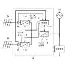
図1はこの発明の第1の実施形態の太陽電池と燃料電池を有する分散電源システムの構成を示すブロック図である。このシステムは、逆潮流を行なう太陽電池1と、逆潮流を行なわない燃料電池2と、これらの直流出力を商用周波数の交流電力に変換して商用系統電源20と接続する系統連系インバータ16と、この系統連系インバータ16の出力側に接続される一般家庭などの交流負荷5と、交流負荷5の消費電力P4を検出する交流電力計測手段9と、燃料電池2の燃料や空気の流量を制御し、燃料電池出力電力P2を制御する燃料電池出力制御手段10とから構成される。
【0018】
系統連系インバータ16について詳細に説明すると、太陽電池1の出力はDC/DCコンバータ11によって商用系統電源と連系するために、所定の電圧に調整される。燃料電池2の出力も同様にしてDC/DCコンバータ12によって電圧の調整が行なわれる。DC/DCコンバータ11,12は、たとえば昇圧チョッパで構成され、昇圧チョッパ内のスイッチング素子のオン時間とオフ時間とのデューティによって電力の調整が行なわれる。
【0019】
DC/DCコンバータ11の出力とDC/DCコンバータ12の出力は並列接続して結合され、インバータ主回路3に入力される。インバータ主回路3は結合された電力を商用周波数の交流電力に変換して商用系統電源20に接続する。
【0020】
図2は図1に示したシステムの動作を説明するためのフローチャートである。
次に、図2を参照して図1の動作について説明する。燃料電池2の出力電力P2は直流電力計測手段6によって出力電圧と電流が検出される。直流電力計測手段6では、この検出値をもとに燃料電池出力電力P2を算出し、燃料電池出力電力データD2として電力比較手段8へ出力する。複数の燃料電池が接続されたシステムにおいては、各燃料電池出力電力P2の合計を燃料電池出力データD2とする。
【0021】
また、交流電力計測手段9は交流負荷5の消費する電圧と電流を検出し、この検出値をもとに交流負荷消費電力P4を算出し、交流負荷消費電力データD4として電力比較手段8へ出力する。電力比較手段8は燃料電池出力電力データD2と交流負荷の消費電力データD4とを比較するため、交流負荷5の消費電力から燃料電池2の出力電力を減算し、電力比較結果S1を制御信号発生手段17に出力する。
【0022】
ここで、電力比較結果S1は第(1)式で示される。
S1=D4−D2……(1)
制御信号発生手段17は電力比較結果S1が負であるか否かを判別し、負でない場合燃料電池2の出力を現在の状態に保ち、負の場合には出力を抑制するように、燃料電池出力制御手段10に対して燃料電池出力制御信号S2を出力する。
【0023】
上述の一連の動作において、図1に示した太陽電池1の出力は1kWであり、燃料電池2の出力は1kWであり、交流負荷5の消費電力が3kWの場合、系統連系インバータ16において直流電力計測手段6は燃料電池2の出力1kWを計測し、電力比較手段8に送出する。
【0024】
太陽電池1の出力1kWと燃料電池2の出力1kWが結合され、2kWの電力となり、インバータ主回路3によって商用周波数の交流電力に変換される。この変換された2kWの電力は商用系統電源20に連系され、交流負荷5に供給される。交流負荷5は3kWの電力を消費するため、不足分の1kWについては、商用系統電源20から供給を受ける。このとき、交流電力計測手段9は交流負荷5の消費電力3kWを計測し、電力比較手段8に送出する。電力比較手段8においては、各電力計測手段6,9で計測された燃料電池2の出力電力1kWと交流負荷5の消費電力3kWを用いて、電力比較結果S1=3−1=2を得る。
【0025】
制御信号発生回路17において、この電力比較結果S1が負でないと判断され、燃料電池出力調整回路10に対して現在の出力を維持するように燃料電池出力制御信号S2が送出される。燃料電池出力調整回路10は燃料電池出力制御信号S2を受け、出力を維持するように運転する。
【0026】
次に、上述の運転条件において、交流負荷5の消費電力が1.5kWに減少した場合、太陽電池1の出力1kWと燃料電池2の出力1kWは、上述の説明と同様に2kWの交流電力に変換される。この変換された2kWの電力は商用系統電源20に連系され、交流負荷5に供給される。
【0027】
交流負荷5は1.5kWの電力しか消費しないため、余剰分の0.5kWについては、商用系統電源20へ逆潮流を行なう。交流電力計測手段9は交流負荷5の消費電力が1.5kWに減少したことを検出し、電力比較手段8に送出する。
電力比較手段8では、電力比較結果S1=1.5−1=0.5が得られ、燃料電池2は上述の説明と同様にして現在の出力を維持する。
【0028】
次に、上述の運転条件において、交流負荷5の消費電力が0.5kWに減少した場合、太陽電池1の出力1kWと燃料電池2の出力1kWが、同様にして2kWの交流電力に変換される。変換された2kWの電力は商用系統電源20に連系され、交流負荷5に供給される。交流負荷5は0.5kWの電力しか消費しない。
【0029】
このとき、交流電力計測手段9は交流負荷5の消費電力が0.5kWに減少したことを検出し、電力比較手段8に送出する。電力比較手段8においては、各電力計測手段6,9で計測された燃料電池2の出力電力1kWと交流負荷5の消費電力0.5kWを用いて、電力比較結果S1=0.5−1=−0.5を得る。
【0030】
制御信号発生手段17において、この電力比較結果S1は負であると判別され、燃料電池出力制御手段10に対して電力比較結果S1の0.5kW分だけ出力を減少するように、燃料電池出力制御信号S2を送出する。
【0031】
燃料電池出力制御手段10はその燃料電池出力制御信号S2を受け、出力を0.5kWに減少して運転する。その結果、太陽電池1が1kWを出力し、燃料電池2が0.5kWを出力し、交流負荷5が0.5kWの電力を消費する状態となる。太陽電池1の出力1kWと燃料電池2の出力0.5kWは、上述の説明と同様にして1.5kWの交流電力に変換される。この変換された1.5kWの電力は商用系統電源20に連系され、交流負荷5に供給される。
【0032】
交流負荷5は0.5kWの電力しか消費しないため、余剰分の1kWについては、商用系統電源20へ逆潮流を行なう。交流電力計測手段9は交流負荷5の消費電力が0.5kWであることを検出し、電力比較手段8に送出する。電力比較手段8では電力比較結果S1=0.5−0.5=0が得られ、燃料電池2は上述と同じように現在の出力0.5kWを維持する。
【0033】
これにより、燃料電池2の出力は商用系統電源20に逆潮流することなく、交流負荷5で消費されなかった太陽電池1の出力は商用系統電源20に逆潮流を行なうことができる。
【0034】
図3はこの発明の第2の実施形態の分散電源システムの構成を示すブロック図である。このシステムでは、直流電力計測手段6と交流電力計測手段9が検出電力および燃料電池2の出力を調整する手段が、図1と異なっている。すなわち、このシステムでは、直流電力計測手段6が太陽電池1の出力電力P1を検出し、交流電力計測手段9が商用系統電源20への逆潮流電力P3を検出する。ここで、検出された太陽電池出力電力P1は太陽電池出力電力データD1として、逆潮流電力P3は逆潮流電力データD3として電力比較手段8へ出力される。
【0035】
電力比較手段8は太陽電池出力電力データD1と逆潮流電力データD3を比較するため、商用系統電源20への逆潮流電力から太陽電池1の出力電力を減算し、電力比較結果S1を制御信号発生手段17に出力する。
【0036】
ここで、電力比較S1は第(2)式で表わされる。
S1=D1−D3……(2)
ここで、第(1)式と第(2)式とにおいて、電力比較結果S1は太陽電池出力電力データD1と逆潮流電力データD3の比較結果と、燃料電池出力電力データD2と交流負荷消費電力データD4の比較結果となるが、各電力間には次の第(3)式の関係があるため、比較対象が異なるだけで値は同じなる。
【0037】
P1+P2=P3+P4……(3)
制御信号発生手段17は電力比較結果S1が負であるか否かを判別し、負でない場合には太陽電池2の出力を現在の状態に保ち、負の場合には出力を抑制するようにDC/DCコンバータ制御信号S3をDC/DCコンバータ11に出力し、電力を調整する。
【0038】
第1の実施形態において、直流電力計測手段6が太陽電池1の出力電力P1を検出し、かつ交流電力計測手段9が商用系統電源20への逆潮流電力P3の電力を検出するような構成とすることもできる。
【0039】
また、図3に示したシステムは、第1の実施形態に記載の燃料電池出力制御手段10を備えるようにしてもよく、制御信号発生手段17は燃料電池出力制御手段10に対して燃料電池出力制御信号S2を出力し、燃料電池2の出力制御を行なうこともできる。
【0040】
また、インバータ主回路3にDC/DCコンバータを備え、結合された電力をDC/DCコンバータ制御信号S3によって制御することもできる。
【0041】
また、太陽電池1は複数の太陽電池アレイを含むようにしてもよく、燃料電池2は複数接続することもでき、燃料電池出力制御手段10を各燃料電池ごとに設けてもよい。
【0042】
また、系統連系インバータ16は直流電力計測手段6と電力比較手段8とDC/DCコンバータ11と制御信号発生手段17をそれぞれ独立して外部に設けるようにしてもよい。
【0043】
今回開示された実施の形態はすべての点で例示であって制限的なものではないと考えられるべきである。本発明の範囲は上記した説明ではなくて特許請求の範囲によって示され、特許請求の範囲と均等の意味および範囲内でのすべての変更が含まれることが意図される。
【0044】
【発明の効果】
以上のように、この発明によれば、逆潮流を行なわない直流電力供給手段の出力電力の合計と交流負荷の消費電力とを直接もしくは間接的に計測し、その計測値を電力比較手段において比較し、その比較結果をもとに逆潮流を行なわない直流電力供給手段の出力の合計が交流負荷の消費電力より大きくならないように、逆潮流を行なわない直流電力供給手段の出力電力を制御することができる。
【0045】
これによって、逆潮流を行なわない直流電力供給手段は、交流負荷で消費される電力より多くの電力の供給を行なうことなく、逆潮流を行なう電力のみを商用系統電源に逆潮流することができる。
【0046】
さらに、複数の直流電力供給手段からの供給電力を結合し、1つのインバータにて交流に変換することができるため、装置の簡略化を図ることができる。
【0047】
また、逆潮流を行なわない直流電力供給手段について逆潮流を行なわない直流電力供給手段の出力が制御できない、もしくは制御に対する応答が悪い、あるいは制御を行なうと電力供給効率が低下するなどの場合に、交流負荷の消費電力に応じてインバータ主回路に入力する電力を制御することができ、システム全体としての効率を下げることなく電力の供給を行なうことができる。
【0048】
さらに、直流電力と交流電力の電力検出点を複数から選択することにより、電力検出点をできるだけ少なくするように選択でき、装置の簡略化および低コスト化を図ることができる。
【図面の簡単な説明】
【図1】 この発明の第1の実施形態の分散電源システムの構成を示すブロック図である。
【図2】 図1に示した分散電源システムの動作を説明するためのフローチャートである。
【図3】 この発明の第2の実施形態の分散電源システムの構成を示すブロック図である。
【図4】 従来の太陽電池および燃料電池を用いた分散電源システムの構成を示すブロック図である。
【図5】 従来の複数の太陽電池を有する分散電源システムの構成を示すブロック図である。
【符号の説明】
1 太陽電池、2 燃料電池、3 インバータ主回路、5 交流負荷、6,7直流電力計測手段、8 電力比較手段、9 交流電力計測手段、10 燃料電池出力制御手段、11,12 DC/DCコンバータ、13,14,15 制御部、16 系統連系インバータ、17 制御信号発生手段、20 商用系統電源、100,200 分散電源システム。[0001]
BACKGROUND OF THE INVENTION
The present invention relates to a distributed power supply system, and more particularly to output control of a distributed power supply system that supplies alternating current power by converting direct current output supplied from a plurality of direct current power supply means connected to a commercial power supply into alternating current using an inverter circuit.
[0002]
[Prior art]
In recent years, clean power generation methods such as solar cells and fuel cells have been in the spotlight, but some distributed power systems that convert the DC output to AC power and operate in conjunction with commercial power supplies It has become. In addition, a distributed power supply system combining these new DC power supply means has attracted attention.
[0003]
As shown in FIG. 4, in the distributed
[0004]
On the other hand, in the distributed
[0005]
Further, a system is known in which a plurality of solar cells 1a and 1b as shown in FIG. 5 are connected to the
The outputs of the solar cells 1a and 1b are adjusted in voltage by DC /
[0006]
The output power of each solar cell 1a, 1b is measured by each DC power measuring means 6a, 6b and sent to the
[0007]
Further, a system for supplying power to a load of an energy consumer from a plurality of power supply systems is disclosed in Japanese Patent Laid-Open No. 8-186937. In this system, a solar cell and a commercial system power supply are interconnected, and a power generation device that uses fuel is separated from the commercial system power supply. When the power consumption of the energy consumer load is less than or equal to the maximum power generation amount of the power generator using fuel, this system operates the power generator using fuel, and the power of the energy consumer load uses the fuel. Thus, the electric power supplied by the solar cell and generated by the solar cell is not connected to the load of the energy consumer, and control is performed so that all power flows backward to the commercial power supply.
[0008]
In addition, when the power consumption of the energy consumer's load is greater than the maximum power generation amount of the power generation device using fuel, this system supplies the power generated by the solar cell and the power from the commercial power supply to the energy consumer's load. Control is performed.
[0009]
[Problems to be solved by the invention]
In recent years, with the widespread use of various DC power supply means such as solar cells and fuel cells, distributed power supply systems using a plurality of DC power supply means have been developed. In the system described in the above-mentioned Japanese Patent Application Laid-Open No. 8-186937, when the power generator using fuel is a direct current output and the load of the energy consumer is an alternating current load, the output power of the power generator using the fuel is An inverter circuit for converting to alternating current is required. Since the power generator using fuel is separated from the solar battery and the commercial power supply, the inverter circuit for the power generator using fuel cannot use the inverter circuit for solar battery.
[0010]
Further, as shown in FIG. 4, the outputs of the
[0011]
Therefore, it is possible to reduce the cost and the size of the inverter
[0012]
However, if the hybrid system of the
[0013]
Therefore, even if the main object of the present invention is to convert the AC power into a single inverter circuit, the power supplied from the DC power supply means that does not perform the reverse power flow does not flow backward to the commercial power supply, and the reverse power flows. The supply power of the DC power supply means for performing the power flow is to provide a distributed power supply system capable of performing the reverse power flow.
[0014]
[Means for Solving the Problems]
The present invention relates to a distributed power supply system having a plurality of DC power supply means, and among the plurality of DC power supply means, the total output power of the DC power supply means that does not reversely flow to the commercial power supply and the consumption of the AC load. Based on the comparison output of the power comparison means for comparing the power and the power comparison means, the reverse power flow so that the sum of the output power of each DC power supply means that does not perform the reverse power flow does not become larger than the power consumption of the AC load. Output control means for controlling the output of the DC power supply means that does not perform the operation.
[0015]
The power supply device further includes a power adjustment unit that is connected to an output of the DC power supply unit that does not perform reverse power flow and adjusts the power output from the DC power supply unit to a predetermined power.
[0016]
Furthermore, the first measuring means for measuring the total output power of the DC power supply means that does not perform reverse power flow, the second measuring means for measuring the power consumption of the AC load, and the output of the DC power supply means that performs reverse power flow One of the third measuring means for measuring the total power and the fourth measuring means for measuring the reverse flow power to the commercial power supply is provided, and the power comparing means uses the measured value from each measuring means. The total of the output power of each DC power supply means that does not perform reverse power flow is compared with the power consumption of the AC load.
[0017]
DETAILED DESCRIPTION OF THE INVENTION
FIG. 1 is a block diagram showing a configuration of a distributed power supply system having a solar cell and a fuel cell according to a first embodiment of the present invention. This system includes a
[0018]
The
[0019]
The output of the DC /
[0020]
FIG. 2 is a flowchart for explaining the operation of the system shown in FIG.
Next, the operation of FIG. 1 will be described with reference to FIG. Output power P2 of the
[0021]
Further, the AC power measurement unit 9 detects the voltage and current consumed by the
[0022]
Here, the power comparison result S1 is expressed by the first equation (1).
S1 = D4 −D2 (1)
The control signal generating means 17 determines whether or not the power comparison result S1 is negative. If the power comparison result S1 is not negative, the control signal generating means 17 maintains the output of the
[0023]
In the series of operations described above, when the output of the
[0024]
The
[0025]
The control
[0026]
Next, when the power consumption of the
[0027]
Since the
The power comparison means 8 obtains the power comparison result S1 = 1.5-1 = 0.5, and the
[0028]
Next, when the power consumption of the
[0029]
At this time, the AC power measuring means 9 detects that the power consumption of the
[0030]
The control signal generating means 17 determines that the power comparison result S1 is negative, and the fuel cell output control means 10 decreases the output by 0.5 kW of the power comparison result S1. Output control signal S2 is sent.
[0031]
The fuel cell output control means 10 receives the fuel cell output control signal S2 and operates with the output reduced to 0.5 kW. As a result, the
[0032]
Since the
[0033]
Thereby, the output of the
[0034]
FIG. 3 is a block diagram showing the configuration of the distributed power supply system according to the second embodiment of the present invention. In this system, the means for the DC power measuring means 6 and the AC power measuring means 9 to adjust the detected power and the output of the
[0035]
In order to compare the solar cell output power data D1 and the reverse power flow power data D3 , the power comparison means 8 subtracts the output power of the
[0036]
Here, the power comparison S1 is expressed by the following equation (2).
S1 = D1 −D3 (2)
Here, in the formulas (1) and (2), the power comparison result S1 is the comparison result between the solar cell output power data D1 and the reverse flow power data D3 , and the fuel cell output power data D2 . While the comparison result of the AC load power consumption data D4, because between each power there is a next (3) in relation value is the same by the comparison it is different.
[0037]
P1 + P2 = P3 + P4 (3)
The control signal generation means 17 determines whether or not the power comparison result S1 is negative. If the power comparison result S1 is not negative, the control signal generation means 17 maintains the output of the
[0038]
In the first embodiment, the DC power measuring means 6 detects the output power P1 of the
[0039]
The system shown in FIG. 3 may include the fuel cell output control unit 10 described in the first embodiment, and the control
[0040]
Further, the inverter
[0041]
Further, the
[0042]
Further, the
[0043]
The embodiment disclosed this time should be considered as illustrative in all points and not restrictive. The scope of the present invention is defined by the terms of the claims, rather than the description above, and is intended to include any modifications within the scope and meaning equivalent to the terms of the claims.
[0044]
【The invention's effect】
As described above, according to the present invention, the total output power of the DC power supply means that does not perform reverse power flow and the power consumption of the AC load are measured directly or indirectly, and the measured values are compared in the power comparison means. Based on the comparison result, the output power of the DC power supply means that does not perform the reverse power flow is controlled so that the total output of the DC power supply means that does not perform the reverse power flow does not exceed the power consumption of the AC load. Can do.
[0045]
As a result, the DC power supply means that does not perform reverse power flow can flow only the power that performs reverse power flow to the commercial power supply without supplying more power than the power consumed by the AC load.
[0046]
Furthermore, since the power supplied from a plurality of DC power supply means can be combined and converted into AC by a single inverter, the apparatus can be simplified.
[0047]
Also, in the case where the output of the DC power supply means that does not perform reverse power flow cannot be controlled with respect to the DC power supply means that does not perform reverse power flow, the response to control is poor, or the power supply efficiency decreases when control is performed, The power input to the inverter main circuit can be controlled in accordance with the power consumption of the AC load, and power can be supplied without reducing the efficiency of the entire system.
[0048]
Furthermore, by selecting a plurality of power detection points for DC power and AC power, the power detection points can be selected to be as small as possible, and the apparatus can be simplified and reduced in cost.
[Brief description of the drawings]
FIG. 1 is a block diagram illustrating a configuration of a distributed power supply system according to a first embodiment of this invention.
FIG. 2 is a flowchart for explaining the operation of the distributed power supply system shown in FIG. 1;
FIG. 3 is a block diagram showing a configuration of a distributed power supply system according to a second embodiment of the present invention.
FIG. 4 is a block diagram showing a configuration of a conventional distributed power supply system using a solar cell and a fuel cell.
FIG. 5 is a block diagram showing a configuration of a conventional distributed power supply system having a plurality of solar cells.
[Explanation of symbols]
DESCRIPTION OF
Claims (3)
Translated fromJapanese前記複数の直流電力供給手段に共通に接続され、前記複数の直流電力供給手段からの電力を交流電力に変換して前記商用系統電源に接続するインバータと、
前記複数の直流電力供給手段のうち、前記商用系統電源への逆潮流を行なわない直流電力供給手段の出力電力の合計と交流負荷の消費電力とを比較する電力比較手段と、
前記電力比較手段の比較出力に基づいて、前記逆潮流を行なわない各直流電力供給手段の出力電力の合計が前記交流負荷の消費電力より大きくならないように、該逆潮流を行なわない直流電力供給手段の出力を制御する出力制御手段とを備えた、分散電源システム。In a distributed power supply system havinga plurality of DC power supply meansincluding at least one DC power supply means for performing a reverse power flow to a commercial power supply and at least one DC power supply means for not performing a reverse power flow to the commercial power supply ,
Are connected in common to said plurality of DC power supply means, an inverter connected to convert the power from the plurality of DC power supply means to the AC power tothe commercial power grid,
Among the plurality of DC power supply means, a power comparison means for comparing the total output power of the DC power supply means that does not perform reverse power flow to the commercial power supply and the power consumption of the AC load;
Based on the comparison output of the power comparison means, the direct current power supply means that does not perform reverse flow so that the total output power of the direct current power supply means that does not perform reverse flow does not exceed the power consumption of the alternating current load. A distributed power supply system comprising output control means for controlling the output of the power supply.
前記複数の直流電力供給手段のうち、前記商用系統電源への逆潮流を行なわない直流電力供給手段の出力電力の合計と交流負荷の消費電力とを比較する電力比較手段と、
前記電力比較手段の比較出力に基づいて、前記逆潮流を行なわない各直流電力供給手段の出力電力の合計が前記交流負荷の消費電力より大きくならないように、該逆潮流を行なわない直流電力供給手段の出力を制御する出力制御手段と、
前記逆潮流を行なわない直流電力供給手段の出力電力の合計を計測する第1の計測手段および前記交流負荷の消費電力を計測する第2の計測手段と、
前記逆潮流を行なう直流電力供給手段の出力電力の合計を計測する第3の計測手段および前記商用系統電源への逆潮流電力を計測する第4の計測手段とのいずれか一方を備え、
前記電力比較手段は各計測手段からの計測値を用いて前記逆潮流を行なわない各直流電力供給手段の出力電力の合計と前記交流負荷の消費電力との比較を行なうことを特徴とする、分散電源システム。In a distributed power supply system havinga plurality of DC power supply meansincluding at least one DC power supply means for performing a reverse power flow to a commercial power supply and at least one DC power supply means for not performing a reverse power flow to the commercial power supply ,
Among the plurality of DC power supply unit, a power comparing means for comparing the output power and total power consumption of the AC load of the DC power supply means is not performed backward flow tothe commercial power grid,
Based on the comparison output of the power comparison means, the direct current power supply means that does not perform reverse flow so that the total output power of the direct current power supply means that does not perform reverse flow does not exceed the power consumption of the alternating current load. Output control means for controlling the output of
First measurement means for measuring the total output power of the DC power supply means that does not perform reverse power flow, and second measurement means for measuring the power consumption of the AC load;
One of the third measuring means for measuring the total output power of the DC power supply means for performing the reverse power flow and the fourth measuring means for measuring the reverse power flow to the commercial power supply,
The power comparison means compares the total output power of each DC power supply means that does not perform the reverse power flow with the power consumption of the AC load, using the measurement value from each measurement means. Power system.
Priority Applications (1)
| Application Number | Priority Date | Filing Date | Title |
|---|---|---|---|
| JP2000398017AJP4570245B2 (en) | 2000-12-27 | 2000-12-27 | Distributed power system |
Applications Claiming Priority (1)
| Application Number | Priority Date | Filing Date | Title |
|---|---|---|---|
| JP2000398017AJP4570245B2 (en) | 2000-12-27 | 2000-12-27 | Distributed power system |
Publications (2)
| Publication Number | Publication Date |
|---|---|
| JP2002199592A JP2002199592A (en) | 2002-07-12 |
| JP4570245B2true JP4570245B2 (en) | 2010-10-27 |
Family
ID=18863065
Family Applications (1)
| Application Number | Title | Priority Date | Filing Date |
|---|---|---|---|
| JP2000398017AExpired - LifetimeJP4570245B2 (en) | 2000-12-27 | 2000-12-27 | Distributed power system |
Country Status (1)
| Country | Link |
|---|---|
| JP (1) | JP4570245B2 (en) |
Cited By (1)
| Publication number | Priority date | Publication date | Assignee | Title |
|---|---|---|---|---|
| CN109038536A (en)* | 2017-06-08 | 2018-12-18 | 周锡卫 | A kind of shore-based power supply system and control method based on energy storage peak shaving |
Families Citing this family (19)
| Publication number | Priority date | Publication date | Assignee | Title |
|---|---|---|---|---|
| JP3825020B2 (en)* | 2002-08-01 | 2006-09-20 | 株式会社アイ・ヒッツ研究所 | Distributed power supply system |
| JP5121657B2 (en)* | 2008-10-07 | 2013-01-16 | 株式会社東芝 | Fuel cell cogeneration system |
| US8598741B2 (en) | 2008-12-23 | 2013-12-03 | Samsung Electro-Mechanics Co, Ltd. | Photovoltaic and fuel cell hybrid generation system using single converter and single inverter, and method of controlling the same |
| KR101133328B1 (en)* | 2008-12-23 | 2012-04-05 | 성균관대학교산학협력단 | Photovoltaic and fuel cell hybrid generation system using two converter and one inverter, and control method of the same |
| US8269372B2 (en) | 2008-12-23 | 2012-09-18 | Samsung Electro-Mechanics Co., Ltd. | Photovoltaic and fuel cell hybrid generation system using dual converters and single inverter and method of controlling the same |
| KR101079404B1 (en)* | 2008-12-23 | 2011-11-02 | 성균관대학교산학협력단 | Photovoltaic and fuel cell hybrid generation system using single converter and single inverter, and control method of the same |
| JP5325604B2 (en)* | 2009-02-25 | 2013-10-23 | 旭化成ホームズ株式会社 | Energy monitoring system |
| JP5410118B2 (en)* | 2009-02-27 | 2014-02-05 | 旭化成ホームズ株式会社 | Energy monitoring system |
| JP2011015501A (en)* | 2009-06-30 | 2011-01-20 | Panasonic Electric Works Co Ltd | Power distribution system |
| JP5452422B2 (en)* | 2009-10-29 | 2014-03-26 | 田淵電機株式会社 | Inverter |
| JP5543827B2 (en)* | 2010-03-31 | 2014-07-09 | Jx日鉱日石エネルギー株式会社 | Power system |
| JP5799548B2 (en)* | 2011-03-31 | 2015-10-28 | 株式会社ノーリツ | Power generation system |
| WO2013046713A1 (en) | 2011-09-28 | 2013-04-04 | 京セラ株式会社 | Energy control system, energy control device, and energy control method |
| JP5940309B2 (en)* | 2012-01-20 | 2016-06-29 | 京セラ株式会社 | Power supply system and power supply device |
| US9590422B2 (en)* | 2012-11-26 | 2017-03-07 | Panasonic Intellectual Property Management Co., Ltd. | Power supply system, power conversion apparatus, and measurement point switching apparatus |
| JP6174410B2 (en) | 2013-07-29 | 2017-08-02 | 京セラ株式会社 | Power control apparatus, power control method, and power control system |
| JP6144616B2 (en)* | 2013-12-24 | 2017-06-07 | 京セラ株式会社 | Power control apparatus, power control system, and power control method |
| JP6475945B2 (en)* | 2014-09-26 | 2019-02-27 | 京セラ株式会社 | Power supply device, power supply method, and power supply system |
| NL2016736B1 (en)* | 2016-05-06 | 2017-11-14 | Lens-Ip B V | System for distributing power and method. |
Family Cites Families (5)
| Publication number | Priority date | Publication date | Assignee | Title |
|---|---|---|---|---|
| JPH04308427A (en)* | 1991-04-05 | 1992-10-30 | Nippon Telegr & Teleph Corp <Ntt> | AC power supply system |
| JPH08251827A (en)* | 1995-03-10 | 1996-09-27 | Toshiba Eng & Constr Co Ltd | Combined cycle power generation system |
| JP2000341862A (en)* | 1999-03-19 | 2000-12-08 | Uinzu:Kk | Energy conversion device |
| JP2000340238A (en)* | 1999-05-31 | 2000-12-08 | Nippon Shokuryo Kk | Energy supply system of dwelling house or the like using photovoltaic power generation and fuel cell power generation |
| JP2002010495A (en)* | 2000-06-15 | 2002-01-11 | Sekisui Chem Co Ltd | Power supply system |
- 2000
- 2000-12-27JPJP2000398017Apatent/JP4570245B2/ennot_activeExpired - Lifetime
Cited By (1)
| Publication number | Priority date | Publication date | Assignee | Title |
|---|---|---|---|---|
| CN109038536A (en)* | 2017-06-08 | 2018-12-18 | 周锡卫 | A kind of shore-based power supply system and control method based on energy storage peak shaving |
Also Published As
| Publication number | Publication date |
|---|---|
| JP2002199592A (en) | 2002-07-12 |
Similar Documents
| Publication | Publication Date | Title |
|---|---|---|
| JP4570245B2 (en) | Distributed power system | |
| JP4119081B2 (en) | Power supply system with solar cell | |
| Chen et al. | Double-input PWM DC/DC converter for high-/low-voltage sources | |
| CN104713176B (en) | Photovoltaic air conditioning system and control method thereof | |
| US20040207366A1 (en) | Multi-mode renewable power converter system | |
| US20090079383A1 (en) | Method and apparatus for power conversion with maximum power point tracking and burst mode capability | |
| JP5330941B2 (en) | Equipment control system | |
| US7737669B2 (en) | Hierarchical control for an integrated voltage regulator | |
| WO2007004514A1 (en) | Photovoltaic power generation system utilizing commercial system power supply | |
| KR101849664B1 (en) | Power applying apparatus and method for controlling connecting photo voltaic power generating apparatus | |
| JP7152567B2 (en) | Power converter with dual mode control | |
| JP2004362787A (en) | Fuel cell system with storage means | |
| JP2004080980A (en) | Grid-connected inverter device | |
| Ramanathan et al. | Implementation of modified Z-source inverter integrated for electric vehicle fast charging | |
| JP7026419B1 (en) | Power supply system | |
| JP3798278B2 (en) | Surplus power control method in power supply system | |
| CN119009922A (en) | Photovoltaic direct-current air conditioner flexible adjusting system and method | |
| US20020033332A1 (en) | Water Electrolytic system | |
| Calpbinici et al. | Design of an Energy Management System for AC/DC Microgrid | |
| JP2003092831A (en) | Power supply system and operation method thereof | |
| CN113507135B (en) | Energy conversion system and method for photovoltaic power generation system | |
| JPH07302130A (en) | Power control device | |
| JPH10336890A (en) | Power supply system | |
| JPH06266454A (en) | Photovoltaic power generating equipment capable of jointly using battery | |
| JP2001218368A (en) | Power conversion device and photovoltaic power generation system |
Legal Events
| Date | Code | Title | Description |
|---|---|---|---|
| A621 | Written request for application examination | Free format text:JAPANESE INTERMEDIATE CODE: A621 Effective date:20071211 | |
| A977 | Report on retrieval | Free format text:JAPANESE INTERMEDIATE CODE: A971007 Effective date:20090518 | |
| A131 | Notification of reasons for refusal | Free format text:JAPANESE INTERMEDIATE CODE: A131 Effective date:20090602 | |
| A521 | Request for written amendment filed | Free format text:JAPANESE INTERMEDIATE CODE: A523 Effective date:20090708 | |
| A131 | Notification of reasons for refusal | Free format text:JAPANESE INTERMEDIATE CODE: A131 Effective date:20100615 | |
| A521 | Request for written amendment filed | Free format text:JAPANESE INTERMEDIATE CODE: A523 Effective date:20100715 | |
| TRDD | Decision of grant or rejection written | ||
| A01 | Written decision to grant a patent or to grant a registration (utility model) | Free format text:JAPANESE INTERMEDIATE CODE: A01 Effective date:20100803 | |
| A01 | Written decision to grant a patent or to grant a registration (utility model) | Free format text:JAPANESE INTERMEDIATE CODE: A01 | |
| A61 | First payment of annual fees (during grant procedure) | Free format text:JAPANESE INTERMEDIATE CODE: A61 Effective date:20100810 | |
| FPAY | Renewal fee payment (event date is renewal date of database) | Free format text:PAYMENT UNTIL: 20130820 Year of fee payment:3 | |
| R150 | Certificate of patent or registration of utility model | Ref document number:4570245 Country of ref document:JP Free format text:JAPANESE INTERMEDIATE CODE: R150 Free format text:JAPANESE INTERMEDIATE CODE: R150 | |
| EXPY | Cancellation because of completion of term |