JP4569825B2 - High pressure fuel pump - Google Patents
High pressure fuel pumpDownload PDFInfo
- Publication number
- JP4569825B2 JP4569825B2JP2005308333AJP2005308333AJP4569825B2JP 4569825 B2JP4569825 B2JP 4569825B2JP 2005308333 AJP2005308333 AJP 2005308333AJP 2005308333 AJP2005308333 AJP 2005308333AJP 4569825 B2JP4569825 B2JP 4569825B2
- Authority
- JP
- Japan
- Prior art keywords
- fuel
- valve
- valve body
- pressurizing chamber
- drive unit
- Prior art date
- Legal status (The legal status is an assumption and is not a legal conclusion. Google has not performed a legal analysis and makes no representation as to the accuracy of the status listed.)
- Expired - Fee Related
Links
Images


Classifications
- F—MECHANICAL ENGINEERING; LIGHTING; HEATING; WEAPONS; BLASTING
- F04—POSITIVE - DISPLACEMENT MACHINES FOR LIQUIDS; PUMPS FOR LIQUIDS OR ELASTIC FLUIDS
- F04B—POSITIVE-DISPLACEMENT MACHINES FOR LIQUIDS; PUMPS
- F04B7/00—Piston machines or pumps characterised by having positively-driven valving
- F04B7/0076—Piston machines or pumps characterised by having positively-driven valving the members being actuated by electro-magnetic means
- F—MECHANICAL ENGINEERING; LIGHTING; HEATING; WEAPONS; BLASTING
- F02—COMBUSTION ENGINES; HOT-GAS OR COMBUSTION-PRODUCT ENGINE PLANTS
- F02M—SUPPLYING COMBUSTION ENGINES IN GENERAL WITH COMBUSTIBLE MIXTURES OR CONSTITUENTS THEREOF
- F02M59/00—Pumps specially adapted for fuel-injection and not provided for in groups F02M39/00 -F02M57/00, e.g. rotary cylinder-block type of pumps
- F02M59/44—Details, components parts, or accessories not provided for in, or of interest apart from, the apparatus of groups F02M59/02 - F02M59/42; Pumps having transducers, e.g. to measure displacement of pump rack or piston
- F02M59/46—Valves
- F02M59/464—Inlet valves of the check valve type
- F—MECHANICAL ENGINEERING; LIGHTING; HEATING; WEAPONS; BLASTING
- F02—COMBUSTION ENGINES; HOT-GAS OR COMBUSTION-PRODUCT ENGINE PLANTS
- F02M—SUPPLYING COMBUSTION ENGINES IN GENERAL WITH COMBUSTIBLE MIXTURES OR CONSTITUENTS THEREOF
- F02M59/00—Pumps specially adapted for fuel-injection and not provided for in groups F02M39/00 -F02M57/00, e.g. rotary cylinder-block type of pumps
- F02M59/44—Details, components parts, or accessories not provided for in, or of interest apart from, the apparatus of groups F02M59/02 - F02M59/42; Pumps having transducers, e.g. to measure displacement of pump rack or piston
- F02M59/46—Valves
- F02M59/466—Electrically operated valves, e.g. using electromagnetic or piezoelectric operating means
- F—MECHANICAL ENGINEERING; LIGHTING; HEATING; WEAPONS; BLASTING
- F02—COMBUSTION ENGINES; HOT-GAS OR COMBUSTION-PRODUCT ENGINE PLANTS
- F02M—SUPPLYING COMBUSTION ENGINES IN GENERAL WITH COMBUSTIBLE MIXTURES OR CONSTITUENTS THEREOF
- F02M59/00—Pumps specially adapted for fuel-injection and not provided for in groups F02M39/00 -F02M57/00, e.g. rotary cylinder-block type of pumps
- F02M59/44—Details, components parts, or accessories not provided for in, or of interest apart from, the apparatus of groups F02M59/02 - F02M59/42; Pumps having transducers, e.g. to measure displacement of pump rack or piston
- F02M59/48—Assembling; Disassembling; Replacing
- F02M59/485—Means for fixing delivery valve casing and barrel to each other or to pump casing
- F—MECHANICAL ENGINEERING; LIGHTING; HEATING; WEAPONS; BLASTING
- F04—POSITIVE - DISPLACEMENT MACHINES FOR LIQUIDS; PUMPS FOR LIQUIDS OR ELASTIC FLUIDS
- F04B—POSITIVE-DISPLACEMENT MACHINES FOR LIQUIDS; PUMPS
- F04B49/00—Control, e.g. of pump delivery, or pump pressure of, or safety measures for, machines, pumps, or pumping installations, not otherwise provided for, or of interest apart from, groups F04B1/00 - F04B47/00
- F04B49/22—Control, e.g. of pump delivery, or pump pressure of, or safety measures for, machines, pumps, or pumping installations, not otherwise provided for, or of interest apart from, groups F04B1/00 - F04B47/00 by means of valves
- F04B49/24—Bypassing
- F04B49/243—Bypassing by keeping open the inlet valve
Landscapes
- Engineering & Computer Science (AREA)
- Mechanical Engineering (AREA)
- General Engineering & Computer Science (AREA)
- Chemical & Material Sciences (AREA)
- Combustion & Propulsion (AREA)
- Physics & Mathematics (AREA)
- Electromagnetism (AREA)
- Magnetically Actuated Valves (AREA)
- Fuel-Injection Apparatus (AREA)
- Details Of Reciprocating Pumps (AREA)
Description
Translated fromJapanese本発明は、プランジャの往復移動により加圧室に吸入した燃料を加圧する高圧燃料ポンプに関する。 The present invention relates to a high-pressure fuel pump that pressurizes fuel sucked into a pressurizing chamber by reciprocating movement of a plunger.
プランジャの往復移動により加圧室に吸入した燃料を加圧し吐出する高圧燃料ポンプが公知である(例えば、特許文献1、2参照)。高圧燃料ポンプから吐出された燃料は、例えばデリバリパイプを経由してエンジンの各気筒に設置されたインジェクタへ分配される。このような高圧燃料ポンプでは、加圧室から吐出される燃料の流量を調整するための調量弁が設置されている。調量弁は、加圧室の入口側に設置されている。 A high-pressure fuel pump that pressurizes and discharges fuel sucked into a pressurizing chamber by a reciprocating movement of a plunger is known (see, for example, Patent Documents 1 and 2). The fuel discharged from the high-pressure fuel pump is distributed to injectors installed in each cylinder of the engine via, for example, a delivery pipe. Such a high-pressure fuel pump is provided with a metering valve for adjusting the flow rate of fuel discharged from the pressurizing chamber. The metering valve is installed on the inlet side of the pressurizing chamber.
特許文献1に開示されている高圧燃料ポンプの場合、調量弁は弁体と弁体を駆動する電磁駆動部とが一体に構成されている。この弁体は加圧室に面している。そのため、加圧室内の燃料の圧力が上昇すると、弁体だけでなく弁体と一体の電磁駆動部も燃料の圧力を受ける。その結果、電磁弁には、繰り返し加わる燃料の圧力に耐えうる剛性を確保する必要がある。 In the case of the high-pressure fuel pump disclosed in Patent Document 1, the metering valve is configured integrally with a valve body and an electromagnetic drive unit that drives the valve body. This valve body faces the pressurizing chamber. Therefore, when the pressure of the fuel in the pressurizing chamber increases, not only the valve body but also the electromagnetic drive unit integrated with the valve body receives the fuel pressure. As a result, it is necessary for the solenoid valve to ensure rigidity that can withstand the pressure of the repeatedly applied fuel.
また、特許文献2に開示されている高圧燃料ポンプの場合、電磁弁は弁体と電磁駆動部とが別体に構成されている。電磁駆動部と別体の弁体は、電磁駆動部と加圧室を形成するハウジングとの間に挟み込まれている。しかしながら、弁体を案内する電磁駆動部のガイド部材には加圧室の油圧が加わる。そのため、電磁駆動部には、この弁体を案内するガイド部材を経由して加圧室の油圧が加わる。その結果、電磁駆動部をハウジングに強固に固定する必要があるとともに、固定時の変形を防止するために剛性を高める必要がある。 In the case of the high-pressure fuel pump disclosed in Patent Document 2, the solenoid valve is configured such that the valve body and the electromagnetic drive unit are separately provided. The valve body that is separate from the electromagnetic drive unit is sandwiched between the electromagnetic drive unit and the housing that forms the pressurizing chamber. However, the hydraulic pressure of the pressurizing chamber is applied to the guide member of the electromagnetic drive unit that guides the valve body. Therefore, the hydraulic pressure of the pressurizing chamber is applied to the electromagnetic drive unit via a guide member that guides the valve body. As a result, it is necessary to firmly fix the electromagnetic drive unit to the housing, and it is necessary to increase rigidity in order to prevent deformation at the time of fixing.
上述の特許文献1、2では、電磁弁および電磁弁を構成する電磁駆動部の剛性を高める必要がある。そのため、構造の複雑化および体格の大型化を招くという問題がある。
そこで、本発明の目的は、電磁駆動部が受ける油圧を低減し、簡単な構造で体格の大型化を招かない高圧燃料ポンプを提供することにある。In the above-mentioned Patent Documents 1 and 2, it is necessary to increase the rigidity of the electromagnetic valve and the electromagnetic drive unit that constitutes the electromagnetic valve. Therefore, there is a problem that the structure is complicated and the size of the physique is increased.
SUMMARY OF THE INVENTION An object of the present invention is to provide a high-pressure fuel pump that reduces the hydraulic pressure received by an electromagnetic drive unit and does not increase the size of the physique with a simple structure.
請求項1記載の発明では、高圧燃料ポンプは、ハウジングと、弁部材と、弁ボディと、電磁駆動部とを備える。
ハウジングは、燃料が加圧される加圧室、加圧室へ燃料を導く燃料通路を形成する筒部、および、燃料の流れ方向において前記燃料通路の上流側に配置され燃料が蓄えられる燃料室を有する。
弁部材は、燃料通路から加圧室への燃料の流れを断続する。
弁ボディは、筒部に収容され、弁部材が着座可能なシート面、および内周側に弁部材の外周面と摺動し前記弁部材の移動を案内するガイド面を有する。
ここで、弁部材は、シート面の加圧室側に設置され、シート面と接する、またはシート面から離れることにより、燃料室と加圧室との間の燃料の流れを断続する。
電磁駆動部は、弁部材および弁ボディの燃料室側に設置され、通電の断続により弁部材を駆動する。
規制部材は、係合部材とシール部材とを有し、加圧室で加圧された燃料の圧力が電磁駆動部側へ加わるのを規制する。係合部材は、弁ボディの外壁および燃料通路を形成するハウジングの内壁に噛み合って弁ボディをハウジングに保持する。シール部材は、弁ボディの外周面と燃料通路を形成するハウジングの内周面とをシールする。
そして、弁ボディは、弾性力により電磁駆動部側へ、または電磁駆動部と反対側へ押し付けられる。
これにより、加圧室の燃料は電磁駆動部側への浸入が規制される。
According to the first aspect of the present invention, the high pressure fuel pump includes a housing, a valve member, a valve body, and an electromagnetic drive unit.
The housing includes a pressurizing chamber in which fuel is pressurized, a cylindrical portion that forms a fuel passage that guides the fuel to the pressurizing chamber, and a fuel chamber that is disposed upstream of the fuel passage in the fuel flow direction and stores the fuel. Have
The valve member interrupts the flow of fuel from the fuel passage to the pressurizing chamber.
The valve body has a seat surface that is accommodated in the cylindrical portion and on which the valve member can be seated, and a guide surface that slides on the inner peripheral side with the outer peripheral surface of the valve member and guides the movement of the valve member.
Here, the valve member is installed on the pressurizing chamber side of the seat surface, and interrupts the flow of fuel between the fuel chamber and the pressurizing chamber by contacting the seat surface or moving away from the seat surface.
The electromagnetic drive unit is installed on the fuel chamber side of the valve member and the valve body, and drives the valve member by energization.
The restricting member has an engaging member and a seal member, and restricts the pressure of the fuel pressurized in the pressurizing chamber from being applied to the electromagnetic drive unit side. The engaging member meshes with the outer wall of the valve body and the inner wall of the housing forming the fuel passage to hold the valve body in the housing. The seal member seals the outer peripheral surface of the valve body and the inner peripheral surface of the housing forming the fuel passage.
Then, the valve body is pressed against the electromagnetic drive unit side or the side opposite to the electromagnetic drive unit by elastic force.
This restricts the fuel in the pressurizing chamber from entering the electromagnetic drive unit.
規制部材は、弁ボディの外壁およびハウジングの内壁に噛み合って弁ボディをハウジングに保持する係合部材と、弁部材の移動を案内する弁ボディの外周面と燃料通路を形成するハウジングの内周面とをシールするシール部材を有する。これにより、加圧室で加圧された燃料の圧力が電磁駆動部側へ加わることが防止できる。その結果、構造の複雑化を招くことなく、加圧室側の燃料から電磁駆動部が受ける油圧は低減される。そのため、電磁駆動部の剛性を高める必要はなく、電磁駆動部の体格の大型化を招かない。したがって、簡単な構造で電磁駆動部に加わる油圧を低減することができ、電磁駆動部の大型化を招くことがない。
さらに、弁ボディは係合部材によってハウジングに保持されている。これにより、加圧室の燃料の圧力による力は、弁ボディから係合部材を経由してハウジングに加わる。そのため、加圧室の燃料の圧力による力が電磁駆動部側に伝わることはない。したがって、電磁駆動部の剛性を高める必要はなく、電磁駆動部の体格の大型化を招かない。 The regulating member meshes with the outer wall of the valve body and the inner wall of the housing to hold the valve body in the housing, the outer peripheral surface of the valve body that guides the movement of the valve member, and the inner peripheral surface of the housing that forms a fuel passage And a seal member for sealing the. Thereby, it can prevent that the pressure of the fuel pressurized by the pressurization chamber is added to the electromagnetic drive part side. As a result, the hydraulic pressure received by the electromagnetic drive unit from the fuel on the pressurizing chamber side is reduced without complicating the structure. Therefore, it is not necessary to increase the rigidity of the electromagnetic drive unit, and the size of the electromagnetic drive unit is not increased. Therefore, the hydraulic pressure applied to the electromagnetic drive unit can be reduced with a simple structure, and the size of the electromagnetic drive unit is not increased.
Further, the valve body is held in the housing by the engaging member. Thereby, the force due to the pressure of the fuel in the pressurizing chamber is applied to the housing from the valve body via the engaging member. Therefore, the force due to the pressure of the fuel in the pressurizing chamber is not transmitted to the electromagnetic drive unit side. Therefore, it is not necessary to increase the rigidity of the electromagnetic drive unit, and the size of the electromagnetic drive unit is not increased.
請求項2記載の発明では、段差面と弁ボディとの間に設置される押圧部材を備えている。押圧部材は、弁ボディを電磁駆動部側へ押し付けている。これにより、弁ボディには、常に電磁駆動部側へ力が加わる。そのため、加圧室の圧力変化にともなう弁ボディの軸方向の移動は低減される。したがって、弁ボディの移動にともなうシール部材および係合部材の摩耗を低減することができる。In the invention according to claim2, a pressing member is provided between the step surface and the valve body. The pressing member presses the valve body against the electromagnetic drive unit side. Thereby, a force is always applied to the valve body toward the electromagnetic drive unit. Therefore, the axial movement of the valve body accompanying the pressure change in the pressurizing chamber is reduced. Therefore, wear of the seal member and the engagement member accompanying the movement of the valve body can be reduced.
請求項3記載の発明では、ハウジングと係合部材との間に設置される押圧部材を備えている。押圧部材は、弁ボディを電磁駆動部側へ押し付けている。これにより、弁ボディおよび係合部材には、常に電磁駆動部側へ力が加わる。そのため、加圧室の圧力変化にともなう弁ボディの軸方向の移動は低減される。したがって、弁ボディの移動にともなうシール部材および係合部材の摩耗を低減することができる。The invention according to claim3 includes a pressing member installed between the housing and the engaging member. The pressing member presses the valve body against the electromagnetic drive unit side. Thereby, a force is always applied to the valve body and the engagement member toward the electromagnetic drive unit. Therefore, the axial movement of the valve body accompanying the pressure change in the pressurizing chamber is reduced. Therefore, wear of the seal member and the engagement member accompanying the movement of the valve body can be reduced.
請求項4記載の発明では、ハウジングと係合部材との間に設置される押圧部材を備えている。押圧部材は、弁ボディを段差面側へ押し付けている。これにより、弁ボディおよび係合部材には、常に段差面側へ力が加わる。そのため、加圧室の圧力変化にともなう弁ボディの軸方向の移動は低減される。したがって、弁ボディの移動にともなうシール部材および係合部材の摩耗を低減することができる。According to afourth aspect of the invention, a pressing member is provided between the housing and the engaging member. The pressing member presses the valve body toward the step surface. Thereby, force is always applied to the valve body and the engaging member toward the step surface. Therefore, the axial movement of the valve body accompanying the pressure change in the pressurizing chamber is reduced. Therefore, wear of the seal member and the engagement member accompanying the movement of the valve body can be reduced.
請求項5または6記載の発明では、係合部材は自身が弾性力を有している。そのため、係合部材は、弁ボディを電磁駆動部側または段差面側へ押し付ける。これにより、弁ボディおよび係合部材には、常に電磁駆動部側または段差面側へ力が加わる。その結果、加圧室の圧力変化にともなう弁ボディの軸方向の移動は低減される。したがって、弁ボディの移動にともなうシール部材および係合部材の摩耗を低減することができる。In the invention according to claim5 or6 , the engaging member itself has an elastic force. Therefore, the engaging member presses the valve body against the electromagnetic drive unit side or the step surface side. Thereby, a force is always applied to the valve body and the engaging member toward the electromagnetic drive unit side or the stepped surface side. As a result, the axial movement of the valve body accompanying the pressure change in the pressurizing chamber is reduced. Therefore, wear of the seal member and the engagement member accompanying the movement of the valve body can be reduced.
請求項7記載の発明では、電磁駆動部はニードルとコイルとを有している。ニードルは、弁部材を加圧室側へ押し付ける。加圧室において燃料が加圧されるとき、ニードルは加圧室とは反対側へ吸引されるとともに、弁部材は加圧室側の燃料の圧力により燃料通路を閉塞する。すなわち、加圧室において燃料が加圧されるとき、弁部材は燃料の圧力によって燃料通路を閉塞する。そのため、弁部材とニードルとが接している必要はない。これにより、弁部材に燃料の圧力が加わる場合でも、ニードルを含む電磁駆動部には燃料の圧力が加わらず、電磁駆動部は燃料の圧力を受けない。したがって、電磁駆動部に加わる油圧を低減することができる。In the invention according to claim7 , the electromagnetic drive unit has a needle and a coil. The needle presses the valve member toward the pressurizing chamber. When fuel is pressurized in the pressurizing chamber, the needle is sucked to the opposite side of the pressurizing chamber, and the valve member closes the fuel passage by the pressure of the fuel on the pressurizing chamber side. That is, when the fuel is pressurized in the pressurizing chamber, the valve member closes the fuel passage by the pressure of the fuel. Therefore, the valve member and the needle need not be in contact with each other. As a result, even when fuel pressure is applied to the valve member, no fuel pressure is applied to the electromagnetic drive unit including the needle, and the electromagnetic drive unit does not receive the fuel pressure. Accordingly, the hydraulic pressure applied to the electromagnetic drive unit can be reduced.
以下、本発明の複数の実施形態を図面に基づいて説明する。
(基本構成)
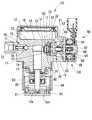
まず、各実施形態に共通する基本構成を説明する。本発明の実施形態による高圧燃料ポンプを図2に示す。高圧燃料ポンプ10は、例えばディーゼルエンジンやガソリンエンジンのインジェクタに燃料を供給する燃料ポンプである。
なお、第1〜第4実施形態と第5〜第16実施形態で対応する部材の名称、符号が異なる場合は、第5〜第16実施形態の部材の名称、符号を[ ]で示す。Hereinafter, a plurality of embodiments of the present invention will be described with reference to the drawings.
(Basic configuration )
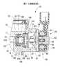
First, a basic configuration common to the embodiments will be described. A high-pressure fuel pump according to an embodiment of the present invention is shown in FIG. The high-
In addition, when the name and code | symbol of a corresponding member differ in 1st-4th embodiment and 5th-16th embodiment, the name and code | symbol of the member of 5th-16th embodiment are shown by [].
図2に示すように、高圧燃料ポンプ10は、ハウジング本体11、カバー12、プランジャ13、調量弁部50および吐出弁部70などを備えている。ハウジング本体11およびカバー12は、特許請求の範囲のハウジングを構成している。ハウジング本体11は、マルテンサイト系ステンレスなどで形成されている。ハウジング本体11は、円筒状のシリンダ14を形成している。ハウジング本体11のシリンダ14には、プランジャ13が軸方向へ往復移動可能に支持されている。 As shown in FIG. 2, the high-
ハウジング本体11は、導入通路21、吸入通路22、加圧室15および吐出通路23などを形成している。ハウジング本体11は筒部16を有している。筒部16は、内部に導入通路21と吸入通路22とを連通する通孔部20を形成している。筒部16は、シリンダ14と概ね垂直に形成されており、内径が途中で変化している。ハウジング本体11は、筒部16において内径が変化する部分に段差面17を形成している。The
燃料室18は、ハウジング本体11とカバー12との間に形成されている。導入通路21は、燃料室18と筒部16の内周側に形成されている通孔部20とを連通している。また、吸入通路22は、一方の端部が加圧室15に連通している。吸入通路22の他方の端部は、段差面17の内周側に開口し、通孔部20に連通している。導入通路21と吸入通路22とは、後述する「中間通路」を経由して連通している。これにより、燃料室18と加圧室15とは、導入通路21、中間通路、および吸入通路22を経由して連通可能である。燃料室18と加圧室15とを連通する導入通路21、中間通路、および吸入通路22は、特許請求の範囲の燃料通路を構成している。加圧室15は、図2に示すように吸入通路22とは反対側において吐出通路23と連通している。The
プランジャ13は、ハウジング本体11のシリンダ14に軸方向へ往復移動可能に支持されている。加圧室15は、プランジャ13の往復移動方向の一端側に形成されている。プランジャ13の他端側に形成されたヘッド13aは、スプリング座81と結合している。スプリング座81とハウジング本体11との間にはスプリング82が設置されている。スプリング座81は、スプリング82の押し付け力によりタペット83の底部831の内壁に押し付けられている。タペット83の底部831外壁が図示しないカムと接することにより、プランジャ13は軸方向へ往復駆動される。タペット83は、タペットガイド84により移動が案内される。タペットガイド84は、ハウジング本体11のシリンダ14の外周側に取り付けられている。 The
プランジャ13のヘッド13a側の外周面と、プランジャ13を収容するシリンダ14を形成しているハウジング本体11の内周面との間は、オイルシール85によりシールされている。オイルシール85は、エンジン内から加圧室15へのオイルの浸入を防止するとともに、加圧室15からエンジンへの燃料の漏れを防止する。 An
燃料出口を形成する吐出弁部70は、ハウジング本体11の吐出通路23に設置されている。吐出弁部70は、加圧室15において加圧された燃料の排出を断続する。吐出弁部70は、弁軸部材71、ボール部材72およびスプリング73を有している。弁軸部材71は、吐出通路23を形成するハウジング本体11に固定されている。スプリング73は、一方の端部が弁軸部材71に接し、他方の端部がボール部材72に接している。ボール部材72は、スプリング73の押し付け力により、ハウジング本体11が形成する弁座74側へ押し付けられている。ボール部材72は、弁座74に着座することにより吐出通路23を閉塞し、弁座74から離座することにより吐出通路23を開放する。ボール部材72は、弁座74とは反対側へ移動したとき、弁軸部材71の端部と接することにより移動が制限される。加圧室15の燃料の圧力が上昇すると、加圧室15側の燃料からボール部材72が受ける力は増大する。そして、加圧室15側の燃料からボール部材72が受ける力がスプリング73の押し付け力と弁座74の下流側の燃料、すなわち、図示しないデリバリパイプ内の燃料からボール部材72が受ける力の和よりも大きくなると、ボール部材72は弁座74から離座する。一方、加圧室15の燃料の圧力が低下すると、加圧室15側の燃料からボール部材72が受ける力は低減する。そして、加圧室15側の燃料からボール部材72が受ける力がスプリング73の押し付ける力と弁座74の下流側の燃料、すなわち、図示しないデリバリパイプ内の燃料からボール部材72が受ける力の和よりも小さくなると、ボール部材72は弁座74に着座する。これにより、吐出弁部70は、加圧室15からの燃料の吐出を断続する逆止弁として機能する。 The
調量弁部50については、第1〜第4実施形態と第5〜第16実施形態とを分けて説明する。 About the
第1〜第4実施形態の調量弁部50は、シート部材30、ガイド部材40、弁部材51、スプリング52および電磁駆動部60を有している。 The
シート部材30は、ハウジング本体11にねじ結合によって固定されるとともに、ハウジング本体11との間にガイド部材40を挟持する。 The
ガイド部材40は、ハウジング本体11とシート部材30との間に挟み込まれている。ガイド部材40は、軸方向の一方の端部にハウジング本体11の段差面17と密着する第一シール面42を有している。ガイド部材40は、第一シール面42とは反対側の端部に第二シール面43を有している。第二シール面43はシート部材30のガイド部材40の端部に形成されるシート面33と密着する。 The
弁部材51は、ガイド部材40の内周側に軸方向へ移動可能に設置されている。弁部材51は、略円環状に形成されている。スプリング52は、弁部材51のシート部材30とは反対側に設置されている。スプリング52は、一方の端部がハウジング本体の壁面19に接しており、他方の端部が弁部材51に接している。弁部材51は、スプリング52によってシート部材30側に押し付けられている。弁部材51は、シート部材30側の端部がシート面33に着座可能である。弁部材51がシート面33に着座することにより、加圧室15と燃料室18との間、すなわち燃料通路が閉塞される。 The
弁部材51は、外周面がガイド部材40のガイド面44と摺動する。これにより、弁部材51は、軸方向への移動がガイド部材40のガイド面44によって案内される。また、ガイド部材40は、内周側に溝41を形成している。これにより、弁部材51がシート部材30から離間したとき、シート部材30の通孔31の燃料は溝41を経由して吸入通路22へ流出する。 The outer peripheral surface of the
第5〜第16実施形態の調量弁部50は、弁ボディ100、弁部材120、スプリング123および電磁駆動部60を有している。弁ボディ100には、弁部材120が着座可能なシート面102が形成されている。また、弁ボディ100の内周面には、弁部材120が摺動可能なガイド面105が形成されている。
弁部材120は、弁ボディ100の内周側に軸方向へ移動可能に設置されている。弁部材120は、略円環状に形成されている。スプリング123は、弁部材120のシート面102とは反対側に設置されている。弁部材120は、スプリング123によってシート面102側に押し付けられている。弁部材120がシート面102に着座することにより、加圧室15と燃料室18との間、すなわち燃料通路が閉塞される。
弁部材120は、外周面がガイド面105と摺動する。これにより、弁部材120は、軸方向への移動がガイド面105によって案内される。
弁部材120がシート面102から離間したとき、燃料は、弁ボディ100の通孔101から吸入通路22へ流出する。The
The
The outer peripheral surface of the
When the
電磁駆動部60は、コイル61、固定コア62、可動コア63、磁性部材64、フランジ65、スプリング66およびニードル67を有している。コイル61は、樹脂部材68の周囲に巻かれており、通電することにより磁界を発生する。固定コア62は、磁性材料から形成されている。固定コア62は、コイル61および磁性部材64の内周側に収容されている。可動コア63は、磁性材料から形成されている。可動コア63は、固定コア62と対向して配置されている。可動コア63は、非磁性材料から形成されている筒部材69の内周側に軸方向へ往復移動可能に収容されている。筒部材69は、可動コア63を収容するとともに、固定コア62とフランジ65との間の磁気的な短絡を防止する。固定コア62と可動コア63との間には、スプリング66が設置されている。スプリング66は、可動コア63を固定コア62とは反対側へ押し付けている。これにより、コイル61に通電していないとき、固定コア62と可動コア63とは互いに離れている。 The
フランジ65は、磁性材料から形成されている。フランジ65は、ハウジング本体11の筒部16に取り付けられている。これにより、フランジ65は、電磁駆動部60をハウジング本体11に保持するとともに、筒部16の端部を塞いでいる。磁性部材64は、コイル61の外周側を覆っている。磁性部材64は、磁性材料から形成され、固定コア62とフランジ65とを磁気的に接続している。フランジ65は連通孔651を有している。これにより、フランジ65の内周側と外周側とは同一の圧力に維持される。 The
可動コア63は、ニードル67と一体に組み付けられている。ニードル67は、可動コア63とは反対側の端部が弁部材51[120]と接触可能である。スプリング66の押し付け力は、スプリング52[123]の押し付け力よりも大きい。そのため、コイル61に通電していないとき、可動コア63と一体のニードル67はスプリング66の押し付け力により弁部材51[120]側へ移動するとともに、弁部材51[120]はシート部材30[弁ボディ100]から離座している。The
(作動)
次に、上記構成の高圧燃料ポンプ10の作動について説明する。
(1)吸入行程
プランジャ13が図2の下方へ移動するとき、コイル61への通電は停止されている。そのため、弁部材51[120]は、スプリング66によって押し付けられている可動コア63と一体のニードル67により加圧室15側へ押し付けられている。その結果、弁部材51[120]は、シート部材30[弁ボディ100]から離座している。また、プランジャ13が図2の下方へ移動するとき、加圧室15の圧力は低下する。そのため、通孔31[101]側の燃料から弁部材51[120]が受ける力は、加圧室15側の燃料から弁部材51[120]が受ける力よりも大きくなる。そのため、弁部材51[120]にはシート面33[102]から離座する方向の力が加わり、弁部材51[120]はシート面33[102]から離座する。これにより、燃料室18は、導入通路21、中間通路、および吸入通路22を経由して加圧室15に連通する。したがって、燃料室18の燃料は、加圧室15へ吸入される。(Operation)
Next, the operation of the high-
(1) Suction stroke When the
(2)戻し行程
プランジャ13が下死点から上死点に向かって上昇するとき、加圧室15の燃料の圧力は上昇し、弁部材51[120]には加圧室15側の燃料からシート面33[102]に着座する方向へ力が加わる。しかし、コイル61へ通電していないとき、ニードル67はスプリング66の押し付け力により、シート面33[102]よりも加圧室15側へ突出している。そのため、弁部材51[120]は、ニードル67によりシート面33[102]側への移動が規制される。その結果、コイル61への通電が停止されている間、弁部材51[120]はシート面33[102]から離間した状態を維持する。これにより、プランジャ13の上昇によって加圧された加圧室15の燃料は、燃料室18から加圧室15へ吸入される場合と逆に、吸入通路22、中間通路、および導入通路21を経由して燃料室18へ戻される。(2) Return stroke When the
(3)加圧行程
戻し行程中にコイル61へ通電すると、コイル61に発生した磁界により、固定コア62、磁性部材64、フランジ65および可動コア63に磁気回路が形成される。これにより、互いに離間している固定コア62と可動コア63との間には磁気吸引力が発生する。固定コア62と可動コア63との間に発生する磁気吸引力がスプリング66の押し付け力よりも大きくなると、可動コア63は固定コア62側へ移動する。そのため、可動コア63と一体のニードル67も、固定コア62側へ移動する。ニードル67が固定コア62側へ移動すると、弁部材51[120]とニードル67とは離間し、弁部材51[120]はニードル67から力を受けない。その結果、弁部材51[120]は、スプリング52[123]の押し付け力および加圧室15側の燃料から受ける力により、シート面33[102]側へ移動する。(3) Pressurization stroke When the
弁部材51[120]がシート面33[102]側へ移動し、弁部材51[120]がシート面33[102]に着座することにより、吸入通路22と通孔31[101]との間は閉塞される。これにより、加圧室15から燃料室18への燃料の戻し行程は終了する。プランジャ13が上昇するとき、加圧室15と燃料室18との間を閉塞することにより、加圧室15から燃料室18へ戻される燃料の量が調整される。その結果、加圧室15で加圧される燃料の量が決定される。When the valve member 51 [120] moves to theseat surface 33 [102] side and thevalve member 51 [120] is seated on theseat surface 33 [102] , the space between the
加圧室15と燃料室18との間が閉塞された状態でプランジャ13がさらに上死点に向けて上昇すると、加圧室15の燃料の圧力は上昇する。加圧室15の燃料の圧力が所定の圧力以上になると、吐出弁部70のスプリング73の押し付け力と弁座74の下流側の燃料、すなわち、図示しないデリバリパイプ内の燃料からボール部材72が受ける力に抗してボール部材72が弁座74から離座する。これにより、吐出弁部70が開弁し、加圧室15で加圧された燃料は吐出通路23を通り高圧燃料ポンプ10から吐出される。高圧燃料ポンプ10から吐出された燃料は、図示しないデリバリパイプに供給されて蓄圧され、インジェクタに供給される。このとき、ニードル67は、弁部材51[120]と離れている。そのため、弁部材51[120]が加圧室15側の燃料から力を受けても、その力は電磁駆動部60のニードル67には伝わらない。When the
プランジャ13が上死点まで移動すると、プランジャ13は再び図2の下方へ移動する。これにより、加圧室15の燃料の圧力は低下するとともに、コイル61へ通電が停止される。そのため、弁部材51[120]は再びシート面33[102]から離れ、加圧室15には燃料室18から燃料が吸入される。
なお、加圧室15の燃料の圧力が所定値まで上昇したとき、コイル61への通電は停止してもよい。加圧室15の燃料の圧力が上昇すると、弁部材51[120]がシート面33[102]から離座する方向へ受ける力よりも、加圧室15側の燃料によって弁部材51[120]がシート面33[102]に着座する方向へ受ける力が大きくなっている。そのため、コイル61への通電を停止しても、弁部材51[120]は加圧室15側の燃料から受ける力によってシート部材30[弁ボディ100]のシート面33[102]への着座状態を維持する。このように、所定の時期にコイル61への通電を停止することにより、電磁駆動部60の消費電力が低減される。
上記の(1)から(3)の行程を繰り返すことにより、高圧燃料ポンプ10は吸入した燃料を加圧して吐出する。燃料の吐出量は、調量弁部50のコイル61への通電タイミングを制御することにより調量される。When the
When the fuel pressure in the pressurizing
By repeating the steps (1) to (3), the high-
(第1実施形態)
第1〜第4実施形態は、特許請求の範囲の弁ボディを備えていないため、参考形態として説明する。第1〜第4実施形態は、弁ボディ100に代えてシート部材30およびガイド部材を備えている。また、弁部材120に代えて弁部材51を備えている。
第1実施形態では、シート部材30をハウジング本体11の筒部16にねじ結合することにより、ガイド部材40はシート部材30によってハウジング本体11との間に挟み込まれている。これにより、ガイド部材40は、第一シール面42がハウジング本体11の段差面17と密着するとともに、第二シール面43がシート部材30のシート面33に密着している。段差面17と第一シール面42、および第二シール面43とシート面33とが密着することにより、加圧室15における燃料の加圧にともなって圧力が上昇した燃料は、段差面17と第一シール面42、および第二シール面43とシート面33とが形成するメタルシールによってシールされる。そのため、加圧室15において圧力が上昇した燃料は、形成されたメタルシールによって電磁駆動部60側への浸入が規制される。また、コイル61に通電しているとき、ニードル67は弁部材51から離れている。その結果、電磁駆動部60は、加圧室15側の高圧の燃料から力を受けない。したがって、電磁駆動部60の剛性を高める必要がなく、電磁駆動部60の体格を大型化する必要はない。
第1実施形態では、導入通路21と吸入通路22とを連通する「中間通路」は、ハウジング本体11の通孔部20、シート部材30の内周側の通孔31およびガイド部材40の溝41によって構成される。(First embodiment)
Since 1st-4th embodiment is not provided with the valve body of a claim, it demonstrates as a reference form. The first to fourth embodiments include a
In the first embodiment, the
In the first embodiment, the “intermediate passage” that connects the
(第2実施形態)
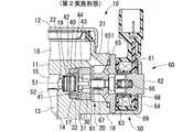
本発明の第2実施形態による高圧燃料ポンプを図3に示す。なお、第1実施形態と実質的に同一の構成部位には同一の符号を付し、説明を省略する。
図3に示す第2実施形態では、シート部材30は筒部16の内周側に圧入されている。すなわち、筒部16の内径は、シート部材30の外径と概ね同一またはやや小さく形成されている。これにより、シート部材30は筒部16の内周側に固定されるとともに、ガイド部材40はシート部材30とハウジング本体11との間に挟み込まれる。(Second Embodiment)
A high-pressure fuel pump according to a second embodiment of the present invention is shown in FIG. In addition, the same code | symbol is attached | subjected to the component substantially the same as 1st Embodiment, and description is abbreviate | omitted.
In the second embodiment shown in FIG. 3, the
第2実施形態では、シート部材30は、ガイド部材40とは反対側の端部に形成される溶接部91おいてハウジング本体11と溶接されている。シート部材30を筒部16に圧入する場合、筒部16の内周面とシート部材30の外周面との間を経由して、加圧室15で加圧された高圧の燃料が電磁駆動部60側へ漏れるおそれがある。そこで、シート部材30とハウジング本体11とを溶接部91において溶接することにより、電磁駆動部60側への燃料の浸入を低減することができる。 In the second embodiment, the
(第3、第4実施形態)
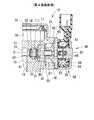
本発明の第3実施形態による高圧燃料ポンプを図4に、第4実施形態による高圧燃料ポンプを図5に示す。なお、第1実施形態と実質的に同一の構成部位には同一の符号を付し、説明を省略する。
第3実施形態では、ガイド部材を省略し、ハウジング本体11にガイド面111を形成している。すなわち、ハウジング本体11は、弁部材51の移動を案内するガイド面111を有している。ガイド面111を形成するハウジング本体11の内周面は、弁部材51の外周面と摺動し、弁部材51の移動を案内する。ガイド面111におけるハウジング本体11の内径は、シート部材30を収容する筒部16の内径よりも小さい。そのため、ガイド面111と筒部16との間には、段差面17が形成される。(Third and fourth embodiments)
FIG. 4 shows a high-pressure fuel pump according to a third embodiment of the present invention, and FIG. 5 shows a high-pressure fuel pump according to the fourth embodiment. In addition, the same code | symbol is attached | subjected to the component substantially the same as 1st Embodiment, and description is abbreviate | omitted.
In the third embodiment, the guide member is omitted, and the
筒部16の内周側には、シート部材30の雄ねじ部32とねじ結合する雌ねじ部112が形成されている。筒部16の内周側にシート部材30をねじ込むことにより、シート部材30のシート面33はハウジング本体11の段差面17に密着する。これにより、ハウジング本体の段差面17とシート部材30のシート面33との間にメタルシールが形成される。 On the inner peripheral side of the
図5に示す第4実施形態では、第3実施形態と同様にガイド部材が省略されている。シート部材30は、第2実施形態と同様に筒部16の内周側に圧入されるとともに、弁部材51とは反対側の端部の溶接部91においてハウジング本体11に溶接されている。
第3実施形態、第4実施形態では、ガイド部材を省略している。そのため、加圧室15から電磁駆動部60側へ高圧の燃料の浸入を防止することができるとともに、部品点数を低減することができる。In the fourth embodiment shown in FIG. 5, the guide member is omitted as in the third embodiment. The
In the third embodiment and the fourth embodiment, the guide member is omitted. Therefore, the high pressure fuel can be prevented from entering from the pressurizing
(第5、第6、第7実施形態)
第5実施形態以降の実施形態は、特許請求の範囲の弁ボディを備えている。
本発明の第5、第6、第7実施形態による高圧燃料ポンプをそれぞれ図6、図7、図8に示す。なお、第1実施形態と実質的に同一の構成部位には同一の符号を付し、説明を省略する。
第5実施形態では、図6に示すようにハウジング本体11の筒部16の内周側に収容される弁ボディ100を備えている。弁ボディ100は、筒状に形成され、内周側に導入通路21と吸入通路22とを連通する通孔101を形成している。ハウジング本体11の内周側には、弁部材120が軸方向へ移動可能に収容されている。弁部材120は、弁ボディ100が形成するシート面102に着座可能である。弁部材120がシート面102から離座すると、導入通路21と吸入通路22との間における燃料の流れは許容される。一方、弁部材120がシート面102に着座すると、導入通路21と吸入通路22との間における燃料の流れは遮断される。
第5実施形態では、導入通路21と吸入通路22とを連通する「中間通路」は、ハウジング本体11の通孔部20、弁ボディ100の通孔101によって構成される。(Fifth, sixth and seventh embodiments)
The fifth and subsequent embodiments include the valve body according to the claims.
High-pressure fuel pumps according to fifth, sixth, and seventh embodiments of the present invention are shown in FIGS. 6, 7, and 8, respectively. In addition, the same code | symbol is attached | subjected to the component substantially the same as 1st Embodiment, and description is abbreviate | omitted.
In 5th Embodiment, as shown in FIG. 6, the
In the fifth embodiment, the “intermediate passage” that connects the
弁ボディ100には、スプリングシート121が設置されている。スプリングシート121は、係止部材122により弁ボディ100に保持されている。係止部材122は、弁ボディ100の内周壁に形成されている溝にはめ込まれている。これにより、係止部材122は、弁ボディ100に固定されている。スプリングシート121には、弾性部材としてのスプリング123の一端が接している。スプリング123の他端は、弁部材120に接している。スプリング123は、軸方向へ伸びる力を有している。これにより、弁部材120は、弁ボディ100のシート面102に着座する方向へ押し付けられている。弁部材120は、弁ボディ100の内周面が形成するガイド面105に案内されて軸方向へ往復移動する。 A
ハウジング本体11と弁ボディ100との間には、シール部材130、131および係合部材としての係合リング140が設置されている。シール部材130、131は、ハウジング本体11の内壁と弁ボディ100の外壁との間に設置され、ハウジング本体11と弁ボディ100との間を液密にシールしている。すなわち、シール部材130、131は、ハウジング本体11の内壁および弁ボディ100の外壁に密着し、加圧室15側から電磁駆動部60側への燃料の浸入を規制している。係合リング140は、円環状に形成されている。係合リング140は、通孔部20を形成するハウジング本体11の内壁に設置された溝24と、弁ボディ100の外壁に設置された溝103とに噛み合っている。係合リング140がハウジング本体11および弁ボディ100の双方に噛み合うことにより、弁ボディ100はハウジング本体11に保持される。シール部材130、131、および係合リング140は、特許請求の範囲の規制部材を構成している。
弁ボディ100と段差面17との間には、押圧部材としてのワッシャ150が設置されている。ワッシャ150は、弾性力により弁ボディ100を電磁駆動部60側へ押し付けるスプリングワッシャである。弁ボディ100は、ワッシャ150の押し付け力により、電磁駆動部60側へ押し付ける。上述のように、弁ボディ100は、ハウジング本体11と噛み合う係合リング140によってハウジング本体11に保持されている。そのため、弁ボディ100は、溝24、溝103および係合リング140などの寸法誤差により軸方向へわずかに移動する。プランジャ13の上昇および下降にともなって加圧室15の燃料の圧力が変化すると、燃料の圧力によって弁ボディ100に加わる力も変化する。その結果、弁ボディ100は軸方向へ移動し、ハウジング本体11と弁ボディ100との間に設置されているシール部材130、131および係合リング140の摩耗を招くおそれがある。そこで、ワッシャ150により弁ボディ100を電磁駆動部60側へ押し付けることにより、弁ボディ100の移動は低減される。したがって、シール部材130、131および係合リング140の摩耗を低減することができる。 A
第5実施形態では、上述の構成により、加圧室15における高圧の燃料はシール部材130、131によってシールされ、電磁駆動部60側へ浸入しない。また、加圧室15の高圧の燃料からの力は、弁部材120、弁ボディ100および係合リング140を経由してハウジング本体11に逃がされる。そのため、電磁駆動部60は、加圧室15の高圧燃料から力を受けない。その結果、電磁駆動部60は、耐圧性および剛性を高める必要がない。したがって、電磁駆動部60の体格を小型化することができる。 In the fifth embodiment, the high-pressure fuel in the pressurizing
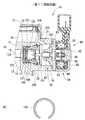
第6実施形態は、図7に示すように係合リング141の断面形状を円形状とする例である。
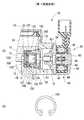
第7実施形態では、図8に示すように係合リング142は周方向の一部に開口部を有する円弧環状、すなわち略C字形状に形成されている。
これらのように、係合リング140、141、142は、断面形状および平面形状を任意に設定することができる。6th Embodiment is an example which makes the cross-sectional shape of the
In the seventh embodiment, as shown in FIG. 8, the
As described above, the
(第8、第9、第10、第11、第12、第13、第14、第15、第16実施形態)
本発明の第8、第9、第10、第11、第12、第13、第14、第15、第16実施形態による高圧燃料ポンプをそれぞれ図9、図10、図11、図12、図13、図14、図15、図16、図17に示す。なお、第5実施形態と実質的に同一の構成部位には同一の符号を付し、説明を省略する。(Eighth, ninth, tenth, eleventh, twelfth, thirteenth, fourteenth, fifteenth and sixteenth embodiments)
The high-pressure fuel pump according to the eighth, ninth, tenth, eleventh, twelfth, thirteenth, fourteenth, fifteenth, and sixteenth embodiments of the present invention is shown in FIGS. 9, 10, 11, 12, and 12, respectively. 13, FIG. 14, FIG. 15, FIG. 16, and FIG. In addition, the same code | symbol is attached | subjected to the component substantially the same as 5th Embodiment, and description is abbreviate | omitted.
第8実施形態では、図9に示すようにワッシャ150は係合リング140とともにハウジング本体11の溝24および弁ボディ100の溝103に設置されている。ワッシャ150は、係合リング140の加圧室15側に設置され、係合リング140を電磁駆動部60側へ押し付けている。これにより、ワッシャ150は、係合リング140を経由して弁ボディ100を電磁駆動部60側へ押し付け、弁ボディ100の移動を低減している。 In the eighth embodiment, as shown in FIG. 9, the
第9実施形態では、図10に示すようにワッシャ150は係合リング140とともにハウジング本体11の溝24および弁ボディ100の溝103に設置されている。ワッシャ150は、係合リング140の電磁駆動部60側に設置され、係合リング140を加圧室15側へ押し付けている。これにより、ワッシャ150は、係合リング140を経由して弁ボディ100を段差面17側へ押し付け、弁ボディ100の移動を低減している。 In the ninth embodiment, as shown in FIG. 10, the
第10実施形態では、図11に示すように係合リング143は軸方向へ伸縮する弾性力を有している。そのため、係合リング143は、弁ボディ100をハウジング本体11に保持するだけでなく、弾性力により弁ボディ100を押し付ける。第10実施形態では、係合リング143は、ハウジング本体11の溝24および弁ボディ100の溝103に設置されている。そして、係合リング143は、弁ボディ100を電磁駆動部60とは反対側へ押し付けている。これにより、弁ボディ100は、係合リング143により段差面17に押し付けられる。 In the tenth embodiment, as shown in FIG. 11, the
第11実施形態では、図12に示すように係合リング144は、第10実施形態とは逆に弁ボディ100を電磁駆動部60側へ押し付けている。
第12、第13、第14実施形態では、それぞれ図13、図14または図15に示すように係合リング145、146、147は、断面形状が第10実施形態と異なっている。第12、第13、第14実施形態の場合、弁ボディ100を押し付ける方向は第10実施形態と同様である。このように、係合リングは、断面形状を任意に選択することができる。
第10から第14実施形態では、弁ボディ100を一方向へ押し付けるためのワッシャが不要となる。したがって、部品点数を低減することができる。In the eleventh embodiment, as shown in FIG. 12, the
In the twelfth, thirteenth, and fourteenth embodiments, the
In the tenth to fourteenth embodiments, a washer for pressing the
第15実施形態では、図16に示すようにワッシャ151は平面形状が他の実施形態と異なっている。ワッシャ151は、例えば図16に示すように星形状や多角形状であってもよい。
第16実施形態では、図17に示すようにスプリングシート121が弁ボディ100の内周側に圧入されている。これにより、第17実施形態では、スプリングシート121を弁ボディ100に固定するための係止部材が不要となる。したがって、部品点数を低減することができる。In the fifteenth embodiment, as shown in FIG. 16, the
In the sixteenth embodiment, the
(その他の実施形態)
上記の第1実施形態および第3実施形態では、シート部材30をハウジング本体11にねじ結合により固定する構成について説明した。この場合、シート部材30の電磁駆動部60側の端部は、ハウジング本体11と溶接してもよい。(Other embodiments)
In the first embodiment and the third embodiment, the configuration in which the
10 高圧燃料ポンプ、11 ハウジング本体(ハウジング)、12 カバー(ハウジング)、15 加圧室、16 筒部、17 段差面、18 燃料室、20 通孔部(燃料通路)、21 導入通路(燃料通路)、22 吸入通路(燃料通路)、30 シート部材、31 通孔(燃料通路)、32 雄ねじ部、33 シート面、40 ガイド部材、41 溝(燃料通路)、42 第一シール面、43 第二シール面、44 ガイド面、51 弁部材、60 電磁駆動部、61 コイル、67 ニードル、100 弁ボディ、101 通孔、102 シート面、105 ガイド面、111 ガイド部、112、161 雌ねじ部、120 弁部材、130、131 シール部材(規制部材)、140、141、142 係合リング(規制部材、係合部材)、143、144、145、146、147 係合リング(規制部材、係合部材、押圧部材)、150、151 ワッシャ(押圧部材) DESCRIPTION OF
Claims (7)
Translated fromJapanese前記燃料通路から前記加圧室への燃料の流れを断続する弁部材と、
前記筒部に収容され、前記弁部材が着座可能なシート面、および内周側に前記弁部材の外周面と摺動し前記弁部材の移動を案内するガイド面を有する弁ボディであって、
前記シート面の前記加圧室側に設置される前記弁部材が前記シート面と接する、または前記シート面から離れることにより、前記燃料室と前記加圧室との間の燃料の流れを断続させる弁ボディと、
前記弁部材および前記弁ボディの前記燃料室側に設置され、通電の断続により前記弁部材を駆動する電磁駆動部と、
前記弁ボディの外壁および前記燃料通路を形成する前記ハウジングの内壁に噛み合って前記弁ボディを前記ハウジングに保持する係合部材と、前記弁ボディの外周面と前記燃料通路を形成する前記ハウジングの内周面とをシールするシール部材とを有し、前記加圧室で加圧された燃料の圧力が前記電磁駆動部側へ加わるのを規制する規制部材と、
を備え、
前記弁ボディは、弾性力により前記電磁駆動部側へ、または前記電磁駆動部と反対側へ押し付けられることを特徴とする高圧燃料ポンプ。A pressurizing chamber in which fuel is pressurized, a cylinder part that forms a fuel passage that guides the fuel to the pressurizing chamber, and a fuel chamber that is disposed upstream of the fuel passage in the fuel flow direction and stores the fuel. A housing;
A valve member for interrupting the flow of fuel from the fuel passage to the pressurizing chamber;
A valve body having a seat surface that is accommodated in the cylindrical portion and on which the valve member can be seated, and a guide surface that slides on the inner peripheral side with the outer peripheral surface of the valve member to guide the movement of the valve member;
The flow of fuel between the fuel chamber and the pressurizing chamber is interrupted when the valve member installed on the pressurizing chamber side of the seat surface contacts or separates from the seat surface. A valve body;
An electromagnetic drive unit installed on the fuel chamber side of the valve member and the valve body, and driving the valve member by energization;
An engagement member that meshes with an outer wall of the valve body and an inner wall of the housing that forms the fuel passage, and holds the valve body on the housing; an inner surface of the housing that forms the fuel passage with an outer peripheral surface of the valve body A regulating member that seals the peripheral surface, and a regulating member that regulates the pressure of the fuel pressurized in the pressurizing chamber from being applied to the electromagnetic drive unit side;
Equipped witha,
The high-pressure fuel pump, wherein the valve body is pressed against the electromagnetic drive unit side or the opposite side of the electromagnetic drive unit by elastic force .
前記加圧室から前記燃料通路へ燃料を戻すとき、前記ニードルは前記弁部材を前記加圧室側へ押し付けるとともに、前記ニードルに押し付けられた前記弁部材は前記燃料通路を開放し、
前記加圧室において燃料を加圧するとき、前記コイルに通電され前記ニードルは前記加圧室とは反対側へ吸引されるとともに、前記弁部材は前記加圧室側の燃料の圧力により前記燃料通路を閉塞することを特徴とする請求項1から6のいずれか一項記載の高圧燃料ポンプ。The electromagnetic drive unit includes a needle that presses the valve member toward the pressurizing chamber, and a coil that generates a magnetic attraction force that attracts the needle when energized.
When returning the fuel from the pressurizing chamber to the fuel passage, the needle presses the valve member toward the pressurizing chamber, and the valve member pressed against the needle opens the fuel passage,
When pressurizing fuel in the pressurizing chamber, the coil is energized, the needle is sucked to the opposite side of the pressurizing chamber, and the valve member is driven by the fuel pressure on the pressurizing chamber side. The high-pressure fuel pump according to any one of claims 1 to6 , wherein the high-pressure fuel pump is closed.
Priority Applications (3)
| Application Number | Priority Date | Filing Date | Title |
|---|---|---|---|
| JP2005308333AJP4569825B2 (en) | 2005-04-26 | 2005-10-24 | High pressure fuel pump |
| US11/410,253US7717089B2 (en) | 2005-04-26 | 2006-04-25 | High pressure pump having solenoid actuator |
| EP06113038.1AEP1717446B1 (en) | 2005-04-26 | 2006-04-25 | High pressure pump having solenoid actuator |
Applications Claiming Priority (2)
| Application Number | Priority Date | Filing Date | Title |
|---|---|---|---|
| JP2005127743 | 2005-04-26 | ||
| JP2005308333AJP4569825B2 (en) | 2005-04-26 | 2005-10-24 | High pressure fuel pump |
Publications (2)
| Publication Number | Publication Date |
|---|---|
| JP2006329180A JP2006329180A (en) | 2006-12-07 |
| JP4569825B2true JP4569825B2 (en) | 2010-10-27 |
Family
ID=36608768
Family Applications (1)
| Application Number | Title | Priority Date | Filing Date |
|---|---|---|---|
| JP2005308333AExpired - Fee RelatedJP4569825B2 (en) | 2005-04-26 | 2005-10-24 | High pressure fuel pump |
Country Status (3)
| Country | Link |
|---|---|
| US (1) | US7717089B2 (en) |
| EP (1) | EP1717446B1 (en) |
| JP (1) | JP4569825B2 (en) |
Cited By (1)
| Publication number | Priority date | Publication date | Assignee | Title |
|---|---|---|---|---|
| JP2013540236A (en)* | 2010-11-18 | 2013-10-31 | ローベルト ボツシユ ゲゼルシヤフト ミツト ベシユレンクテル ハフツング | Fuel system flow control valve |
Families Citing this family (22)
| Publication number | Priority date | Publication date | Assignee | Title |
|---|---|---|---|---|
| US20080203347A1 (en)* | 2007-02-28 | 2008-08-28 | Santos Burrola | Control valve for a gas direct injection fuel system |
| DE102008000658B4 (en) | 2007-03-29 | 2018-09-27 | Denso Corporation | Hydraulic pump |
| EP2055953B1 (en)* | 2007-11-01 | 2018-08-15 | Danfoss Power Solutions Aps | Fluid working machine |
| EP2055942B1 (en)* | 2007-11-01 | 2012-06-06 | Sauer-Danfoss ApS | Hydraulic system with supplement pump |
| DE102010039691A1 (en)* | 2009-12-01 | 2011-06-09 | Robert Bosch Gmbh | Schaltvenitl, in particular for metering a fluid for a downstream pump arranged |
| JP5012922B2 (en)* | 2010-02-03 | 2012-08-29 | 株式会社デンソー | High pressure pump |
| DE102011004993A1 (en)* | 2011-03-02 | 2012-09-06 | Robert Bosch Gmbh | Valve device for switching or metering a fluid |
| DE102011005485A1 (en)* | 2011-03-14 | 2012-09-20 | Robert Bosch Gmbh | Valve device for switching or metering a fluid |
| JP5731562B2 (en)* | 2012-07-04 | 2015-06-10 | 株式会社デンソー | High pressure pump |
| DE102012109074A1 (en) | 2012-09-26 | 2014-03-27 | Sauer-Danfoss Gmbh & Co. Ohg | Method and device for controlling an electrically commutated fluid working machine |
| ITMI20131306A1 (en)* | 2013-08-01 | 2015-02-02 | Bosch Gmbh Robert | PUMPING GROUP FOR FUEL SUPPLEMENTATION, PREFERABLY GASOIL, TO AN INTERNAL COMBUSTION ENGINE |
| DE102013220877A1 (en)* | 2013-10-15 | 2015-04-16 | Continental Automotive Gmbh | Valve |
| DE102013220768A1 (en)* | 2013-10-15 | 2015-04-16 | Continental Automotive Gmbh | valve assembly |
| JP2016125460A (en) | 2015-01-08 | 2016-07-11 | 株式会社デンソー | High pressure fuel pump |
| JP5971361B2 (en)* | 2015-02-03 | 2016-08-17 | 株式会社デンソー | High pressure pump |
| JP6032312B2 (en)* | 2015-03-26 | 2016-11-24 | 株式会社デンソー | High pressure pump |
| GB201508608D0 (en) | 2015-05-20 | 2015-07-01 | Delphi Int Operations Lux Srl | Fuel pump apparatus |
| JP6462873B2 (en)* | 2015-06-25 | 2019-01-30 | 日立オートモティブシステムズ株式会社 | Flow control valve and high-pressure fuel supply pump |
| JP6695768B2 (en)* | 2016-09-29 | 2020-05-20 | 株式会社ケーヒン | Fuel pump |
| US11499515B2 (en) | 2019-02-08 | 2022-11-15 | Delphi Technologies Ip Limited | Fuel pump and inlet valve assembly thereof |
| EP3980646B1 (en) | 2019-05-30 | 2025-05-07 | Motor Components LLC | Fuel pump |
| US12305671B2 (en) | 2020-11-06 | 2025-05-20 | G.W. Lisk Company, Inc. | Electro-hydrostatic actuator |
Family Cites Families (10)
| Publication number | Priority date | Publication date | Assignee | Title |
|---|---|---|---|---|
| US1640742A (en)* | 1924-05-21 | 1927-08-30 | Gen Motors Res Corp | Pump |
| US5415489A (en)* | 1993-01-11 | 1995-05-16 | Zymark Corporation | Reciprocating driver apparatus |
| DE19834121A1 (en)* | 1998-07-29 | 2000-02-03 | Bosch Gmbh Robert | Fuel supply system of an internal combustion engine |
| JP2000186649A (en)* | 1998-12-24 | 2000-07-04 | Isuzu Motors Ltd | Variable discharge quantity control type high pressure fuel pump |
| EP1162365A4 (en)* | 1999-02-09 | 2004-06-23 | Hitachi Ltd | HIGH PRESSURE FUEL SUPPLY PUMP AS PART OF AN INTERNAL COMBUSTION ENGINE |
| JP4285883B2 (en) | 2000-04-18 | 2009-06-24 | 株式会社デンソー | Solenoid valve and fuel supply device using the same |
| JP2003113759A (en)* | 2001-10-03 | 2003-04-18 | Hitachi Ltd | High pressure fuel supply pump |
| JP3823060B2 (en)* | 2002-03-04 | 2006-09-20 | 株式会社日立製作所 | High pressure fuel supply pump |
| DE10247133B4 (en)* | 2002-10-09 | 2009-12-31 | Infineon Technologies Ag | Controlled current source, in particular for digital-to-analog converters in continuous-time sigma-delta modulators |
| US7255290B2 (en)* | 2004-06-14 | 2007-08-14 | Charles B. Bright | Very high speed rate shaping fuel injector |
- 2005
- 2005-10-24JPJP2005308333Apatent/JP4569825B2/ennot_activeExpired - Fee Related
- 2006
- 2006-04-25EPEP06113038.1Apatent/EP1717446B1/ennot_activeCeased
- 2006-04-25USUS11/410,253patent/US7717089B2/enactiveActive
Cited By (1)
| Publication number | Priority date | Publication date | Assignee | Title |
|---|---|---|---|---|
| JP2013540236A (en)* | 2010-11-18 | 2013-10-31 | ローベルト ボツシユ ゲゼルシヤフト ミツト ベシユレンクテル ハフツング | Fuel system flow control valve |
Also Published As
| Publication number | Publication date |
|---|---|
| EP1717446B1 (en) | 2018-11-28 |
| JP2006329180A (en) | 2006-12-07 |
| EP1717446A3 (en) | 2012-01-25 |
| EP1717446A2 (en) | 2006-11-02 |
| US7717089B2 (en) | 2010-05-18 |
| US20060239846A1 (en) | 2006-10-26 |
Similar Documents
| Publication | Publication Date | Title |
|---|---|---|
| JP4569825B2 (en) | High pressure fuel pump | |
| JP4318730B2 (en) | High pressure fuel pump | |
| JP2008248788A (en) | High pressure fuel pump | |
| JP5126604B2 (en) | High pressure pump | |
| JP5126603B2 (en) | High pressure pump | |
| JP5682335B2 (en) | High pressure pump | |
| EP1788233B1 (en) | High-pressure fuel pump | |
| JP5126606B2 (en) | High pressure pump | |
| JP4958023B2 (en) | High pressure pump | |
| JP2007138805A (en) | High pressure fuel pump | |
| JP6032312B2 (en) | High pressure pump | |
| JP5321982B2 (en) | High pressure pump | |
| JP5929973B2 (en) | High pressure pump | |
| JP6721073B2 (en) | High pressure pump | |
| JP6988953B2 (en) | High pressure pump | |
| JP4332898B2 (en) | High pressure fuel pump | |
| JP6443412B2 (en) | High pressure pump | |
| JP6337874B2 (en) | High pressure pump | |
| JP5971361B2 (en) | High pressure pump | |
| JP5582234B2 (en) | High pressure pump | |
| JP5582235B2 (en) | High pressure pump | |
| JP5344327B2 (en) | High pressure pump | |
| JP5126602B2 (en) | High pressure pump | |
| JP2018109413A (en) | High-pressure pump |
Legal Events
| Date | Code | Title | Description |
|---|---|---|---|
| A621 | Written request for application examination | Free format text:JAPANESE INTERMEDIATE CODE: A621 Effective date:20071207 | |
| A131 | Notification of reasons for refusal | Free format text:JAPANESE INTERMEDIATE CODE: A131 Effective date:20091008 | |
| A977 | Report on retrieval | Free format text:JAPANESE INTERMEDIATE CODE: A971007 Effective date:20091008 | |
| A521 | Request for written amendment filed | Free format text:JAPANESE INTERMEDIATE CODE: A523 Effective date:20091127 | |
| A131 | Notification of reasons for refusal | Free format text:JAPANESE INTERMEDIATE CODE: A131 Effective date:20100326 | |
| A521 | Request for written amendment filed | Free format text:JAPANESE INTERMEDIATE CODE: A523 Effective date:20100423 | |
| TRDD | Decision of grant or rejection written | ||
| A01 | Written decision to grant a patent or to grant a registration (utility model) | Free format text:JAPANESE INTERMEDIATE CODE: A01 Effective date:20100715 | |
| A01 | Written decision to grant a patent or to grant a registration (utility model) | Free format text:JAPANESE INTERMEDIATE CODE: A01 | |
| A61 | First payment of annual fees (during grant procedure) | Free format text:JAPANESE INTERMEDIATE CODE: A61 Effective date:20100728 | |
| FPAY | Renewal fee payment (event date is renewal date of database) | Free format text:PAYMENT UNTIL: 20130820 Year of fee payment:3 | |
| R151 | Written notification of patent or utility model registration | Ref document number:4569825 Country of ref document:JP Free format text:JAPANESE INTERMEDIATE CODE: R151 | |
| FPAY | Renewal fee payment (event date is renewal date of database) | Free format text:PAYMENT UNTIL: 20130820 Year of fee payment:3 | |
| R250 | Receipt of annual fees | Free format text:JAPANESE INTERMEDIATE CODE: R250 | |
| R250 | Receipt of annual fees | Free format text:JAPANESE INTERMEDIATE CODE: R250 | |
| R250 | Receipt of annual fees | Free format text:JAPANESE INTERMEDIATE CODE: R250 | |
| R250 | Receipt of annual fees | Free format text:JAPANESE INTERMEDIATE CODE: R250 | |
| R250 | Receipt of annual fees | Free format text:JAPANESE INTERMEDIATE CODE: R250 | |
| R250 | Receipt of annual fees | Free format text:JAPANESE INTERMEDIATE CODE: R250 | |
| R250 | Receipt of annual fees | Free format text:JAPANESE INTERMEDIATE CODE: R250 | |
| R250 | Receipt of annual fees | Free format text:JAPANESE INTERMEDIATE CODE: R250 | |
| R250 | Receipt of annual fees | Free format text:JAPANESE INTERMEDIATE CODE: R250 | |
| LAPS | Cancellation because of no payment of annual fees |