JP4568731B2 - 3D display device - Google Patents
3D display deviceDownload PDFInfo
- Publication number
- JP4568731B2 JP4568731B2JP2006545010AJP2006545010AJP4568731B2JP 4568731 B2JP4568731 B2JP 4568731B2JP 2006545010 AJP2006545010 AJP 2006545010AJP 2006545010 AJP2006545010 AJP 2006545010AJP 4568731 B2JP4568731 B2JP 4568731B2
- Authority
- JP
- Japan
- Prior art keywords
- display
- stereoscopic
- image
- see
- light
- Prior art date
- Legal status (The legal status is an assumption and is not a legal conclusion. Google has not performed a legal analysis and makes no representation as to the accuracy of the status listed.)
- Expired - Fee Related
Links
- 230000005540biological transmissionEffects0.000claimsdescription62
- 230000008859changeEffects0.000claimsdescription7
- 239000000758substrateSubstances0.000claimsdescription6
- 239000000470constituentSubstances0.000claims1
- 230000003287optical effectEffects0.000description153
- 238000000034methodMethods0.000description27
- 238000010586diagramMethods0.000description26
- 239000000463materialSubstances0.000description19
- 239000004973liquid crystal related substanceSubstances0.000description16
- 238000001514detection methodMethods0.000description10
- 230000000694effectsEffects0.000description10
- 230000010287polarizationEffects0.000description9
- 230000015572biosynthetic processEffects0.000description7
- 238000002834transmittanceMethods0.000description5
- 239000011521glassSubstances0.000description3
- 239000011159matrix materialSubstances0.000description2
- 239000000203mixtureSubstances0.000description2
- 230000008569processEffects0.000description2
- 230000004044responseEffects0.000description2
- 230000001360synchronised effectEffects0.000description2
- 239000000919ceramicSubstances0.000description1
- 230000006866deteriorationEffects0.000description1
- 239000005262ferroelectric liquid crystals (FLCs)Substances0.000description1
- 230000006872improvementEffects0.000description1
- 230000014759maintenance of locationEffects0.000description1
- 230000002093peripheral effectEffects0.000description1
- 230000009467reductionEffects0.000description1
- 230000004043responsivenessEffects0.000description1
- 239000004065semiconductorSubstances0.000description1
- 239000007787solidSubstances0.000description1
Images


Classifications
- G—PHYSICS
- G02—OPTICS
- G02B—OPTICAL ELEMENTS, SYSTEMS OR APPARATUS
- G02B30/00—Optical systems or apparatus for producing three-dimensional [3D] effects, e.g. stereoscopic images
- G02B30/20—Optical systems or apparatus for producing three-dimensional [3D] effects, e.g. stereoscopic images by providing first and second parallax images to an observer's left and right eyes
- G02B30/26—Optical systems or apparatus for producing three-dimensional [3D] effects, e.g. stereoscopic images by providing first and second parallax images to an observer's left and right eyes of the autostereoscopic type
- G02B30/27—Optical systems or apparatus for producing three-dimensional [3D] effects, e.g. stereoscopic images by providing first and second parallax images to an observer's left and right eyes of the autostereoscopic type involving lenticular arrays
- H—ELECTRICITY
- H04—ELECTRIC COMMUNICATION TECHNIQUE
- H04N—PICTORIAL COMMUNICATION, e.g. TELEVISION
- H04N13/00—Stereoscopic video systems; Multi-view video systems; Details thereof
- H04N13/30—Image reproducers
- H04N13/302—Image reproducers for viewing without the aid of special glasses, i.e. using autostereoscopic displays
- H04N13/31—Image reproducers for viewing without the aid of special glasses, i.e. using autostereoscopic displays using parallax barriers
- H04N13/315—Image reproducers for viewing without the aid of special glasses, i.e. using autostereoscopic displays using parallax barriers the parallax barriers being time-variant
- H—ELECTRICITY
- H04—ELECTRIC COMMUNICATION TECHNIQUE
- H04N—PICTORIAL COMMUNICATION, e.g. TELEVISION
- H04N13/00—Stereoscopic video systems; Multi-view video systems; Details thereof
- H04N13/30—Image reproducers
- H04N13/356—Image reproducers having separate monoscopic and stereoscopic modes
- H04N13/359—Switching between monoscopic and stereoscopic modes
- H—ELECTRICITY
- H04—ELECTRIC COMMUNICATION TECHNIQUE
- H04N—PICTORIAL COMMUNICATION, e.g. TELEVISION
- H04N13/00—Stereoscopic video systems; Multi-view video systems; Details thereof
- H04N13/30—Image reproducers
- H04N13/361—Reproducing mixed stereoscopic images; Reproducing mixed monoscopic and stereoscopic images, e.g. a stereoscopic image overlay window on a monoscopic image background
- H—ELECTRICITY
- H04—ELECTRIC COMMUNICATION TECHNIQUE
- H04N—PICTORIAL COMMUNICATION, e.g. TELEVISION
- H04N13/00—Stereoscopic video systems; Multi-view video systems; Details thereof
- H04N13/30—Image reproducers
- H04N13/398—Synchronisation thereof; Control thereof
Landscapes
- Engineering & Computer Science (AREA)
- Multimedia (AREA)
- Signal Processing (AREA)
- Physics & Mathematics (AREA)
- General Physics & Mathematics (AREA)
- Optics & Photonics (AREA)
- Testing, Inspecting, Measuring Of Stereoscopic Televisions And Televisions (AREA)
- Control Of Indicators Other Than Cathode Ray Tubes (AREA)
Description
Translated fromJapaneseこの発明は、立体表示装置に関する。ただし本発明の利用は、前述の立体表示装置には限らない。 The present invention relates to a stereoscopic display device. However, the use of the present invention is not limited to the above-described stereoscopic display device.
立体表示装置は、観察者の左右の眼に各々の視点からの画像(以下、両眼視差画像と呼ぶ)が提示される二眼式が一般的である。かかる方式の立体表示装置では、複数の両眼視差画像を表示してこれらを再構成することにより立体画像を得ることが可能となる。二眼式の立体表示装置において、観察者の左右の眼に各々の両眼視差画像を提示する方法としては、例えば、特殊な偏光眼鏡やシャッタ眼鏡等の眼鏡を用いる方法があげられる。また、眼鏡を用いない方法としては、レンチキュラ式やパララックスステレオグラム式等があげられる。 A stereoscopic display device is generally a binocular system in which images from the respective viewpoints (hereinafter referred to as binocular parallax images) are presented to the left and right eyes of the observer. In such a stereoscopic display device, a stereoscopic image can be obtained by displaying a plurality of binocular parallax images and reconstructing them. In a binocular stereoscopic display device, examples of a method for presenting binocular parallax images to the left and right eyes of an observer include a method using spectacles such as special polarized glasses and shutter glasses. Examples of methods that do not use glasses include a lenticular method and a parallax stereogram method.
また、以前より写真の分野において提案されているインテグラルフォトグラフィ方式(以下、IP方式と略す)を利用した立体表示装置がある。例えば、IP方式の立体表示装置は、表示対象である1つの立体画像を異なる複数の方向から見ることによって得られる複数の平面画像をそれぞれ表示する表示パネルと、この表示パネルの前面(観察側)に配置され、表示パネルの画像を透光部を介して観察するよう構成された非透光性の光制御パネルとを有する。 In addition, there is a stereoscopic display device using an integral photography method (hereinafter abbreviated as IP method) that has been proposed in the field of photography. For example, an IP stereoscopic display device includes a display panel that displays a plurality of planar images obtained by viewing a stereoscopic image that is a display target from a plurality of different directions, and a front surface (observation side) of the display panel. And a non-translucent light control panel configured to observe an image of the display panel through the translucent portion.
また、IP方式の立体表示装置の一例として、表示パネルにおける前述の複数の平面画像の更新と、光制御パネルの透光部の透光性の制御とが同期して行われる方式がある(例えば、特許文献1参照。)。かかる方式では、常時は透光不可能である透光部が逐次選択的に透光可能となるとともに、透光可能となった透光部に対応する平面画像が表示パネルに適宜表示される。そして、このようにして逐次更新されて表示される全ての平面画像を眼の残存保持時間内に見ることにより、全体として所望の立体画像を見ることが可能となる。 In addition, as an example of the IP-type stereoscopic display device, there is a method in which the updating of the plurality of planar images on the display panel and the translucency control of the translucent portion of the light control panel are performed in synchronization (for example, , See Patent Document 1). In such a system, the light-transmitting portions that are normally non-translucent can be sequentially and selectively transmitted, and a flat image corresponding to the light-transmitting portions that are allowed to transmit light is appropriately displayed on the display panel. Then, by viewing all the planar images that are sequentially updated and displayed in this way within the remaining eye retention time, a desired stereoscopic image can be viewed as a whole.
ここでは、このような方式を、特に、マルチプレックスピンホールスキャニング型インテグラルフォトグラフィ方式(以下、MPS−IP方式と略す)と呼ぶ。MPS−IP方式によれば、透光部が逐次透光可能となるとともにこれに同期して平面画像が更新されるので、1つの透光部から観察可能な平面画像が増加する。よって、透光部の透光性が常時変化しない通常のIP方式の場合に比べて、解像度の向上が図られる。 Here, such a method is particularly called a multiplex pinhole scanning type integral photography method (hereinafter abbreviated as MPS-IP method). According to the MPS-IP system, the translucent part can sequentially transmit light, and the planar image is updated in synchronization therewith, so that the planar image that can be observed from one translucent part increases. Therefore, the resolution can be improved as compared with the case of the normal IP method in which the translucency of the translucent part does not always change.
IP方式やMPS−IP方式等の立体表示装置を用いて立体表示を行う場合には、前述のように光制御パネルの透光部を介して表示パネルの画像を観察するので、表示パネルを出射した光は、非透光性の光制御パネルによって遮られる。それゆえ、観察側に到達する透過光の光量が低減され、結果として、立体表示装置の外部観察輝度が低下する。ここで、外部観察輝度とは、立体表示装置を観察した際に認識される輝度のことであり、表示パネルの発光輝度とは区別する。 When stereoscopic display is performed using a stereoscopic display device such as the IP method or the MPS-IP method, the image of the display panel is observed through the light-transmitting part of the light control panel as described above. The light is blocked by a non-translucent light control panel. Therefore, the amount of transmitted light reaching the observation side is reduced, and as a result, the external observation luminance of the stereoscopic display device is lowered. Here, the external observation luminance is luminance recognized when the stereoscopic display device is observed, and is distinguished from the light emission luminance of the display panel.
このように外部観察輝度が低い立体表示装置では、良好な視認性を得るために、表示パネルを高輝度とする必要がある。しかしながら、表示パネルを構成する発光素子の寿命や消費電力等の点から、表示パネルにおける発光輝度の向上には制限があり、それゆえ、立体表示装置において十分な外部観察輝度を実現することは困難である。 In such a stereoscopic display device with low external observation luminance, the display panel needs to have high luminance in order to obtain good visibility. However, there are limitations on the improvement of the light emission luminance in the display panel from the viewpoint of the life of the light emitting elements constituting the display panel, the power consumption, and the like. Therefore, it is difficult to realize sufficient external observation luminance in the stereoscopic display device. It is.
請求項1の発明にかかる立体表示装置は、両眼視差を与える平面画像を表示して立体表示を行う立体表示装置であって、入力された画像データに基づいて、目的の立体画像の構成要素である複数の平面画像を表示する表示手段と、前記表示手段と観察者との間に配置され、前記表示手段からの透光量の調整を行う光制御手段とを備え、前記光制御手段は、非透光性の基体と、前記基体に形成された前記平面画像の可視領域である複数の透光部と、前記透光部の面積を調整して前記透光量の調整を行う透光部調整手段とを有し、前記透光部の透光量が第1の量に調整された立体表示と、前記透光部の透光量が前記第1の量よりも多い第2の量に調整された平面表示とを周波数15Hz以上の速さで切替えて、前記目的の立体画像を表示することを特徴とする。 A stereoscopic display device according to a first aspect of the present invention is a stereoscopic display device that performs stereoscopic display by displaying a planar image that gives binocular parallax, and is based on input image data and is a component of a target stereoscopic image Display means for displaying a plurality of planar images, and light control means arranged between the display means and the observer for adjusting the amount of light transmitted from the display means, the light control means A non-translucent substrate, a plurality of translucent portions that are visible regions of the planar image formed on the substrate, and a translucent portion that adjusts the translucent amount by adjusting the area of the translucent portion A stereoscopic display in which the light transmission amount of the light transmission portion is adjusted to a first amount, and a second amount in which the light transmission amount of the light transmission portion is greater than the first amount. To display the target stereoscopic image by switching to the flat display adjusted to a frequency of 15 Hz or higher. And features.
以下に、本発明にかかる立体表示装置の好適な実施の形態を詳細に説明する。この実施の形態は、良好な表示特性で立体画像を表示することが可能であり、かつ、外部観察輝度の向上を図って良好な視認性を実現することが可能な立体表示装置を提供することを目的の1つとする。 Hereinafter, preferred embodiments of the stereoscopic display device according to the present invention will be described in detail. This embodiment provides a stereoscopic display device that can display a stereoscopic image with good display characteristics and can achieve good visibility by improving external observation luminance. Is one of the purposes.
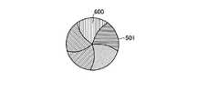
まず、図1は、本発明の実施の形態にかかる立体表示装置により表示される3次元立体画像(以下、単に立体画像と呼ぶ)の構成を示す模式図である。すなわち、ここでは、図1に示す立体画像10が、立体表示装置の表示対象物、言い換えれば目的とする画像に相当する。図1に示すように、立体画像10は、2次元平面で構成される背景11から、3次元立体形状を有する球体12が浮遊した状態、すなわち、背景11から球体12が飛び出した状態を示している。このように、立体画像10は、平面成分(具体的には背景部分)である背景11と、立体成分(具体的には飛び出し部分)である球体12とを含んで構成される。 First, FIG. 1 is a schematic diagram illustrating a configuration of a three-dimensional stereoscopic image (hereinafter simply referred to as a stereoscopic image) displayed by the stereoscopic display device according to the embodiment of the present invention. That is, here, the
図2〜図5は、図1の立体画像10の表示に用いられる構成要素平面画像を示す模式図である。ここで、構成要素平面画像とは、図1の立体画像10の表示に用いられる両眼視差画像のことであり、これらの構成要素平面画像が逐次表示されることによって、目的とする図1の立体画像10が得られる。ここでは、図2〜図5に示すように、図1の矢印13〜16の方向で示す第1方向〜第4方向の各方向から図1の立体画像10を観察してそれぞれ得られる構成要素平面画像20a〜20dによって、図1の立体画像10の表示が実現される。 2 to 5 are schematic diagrams showing component planar images used for displaying the
図2に示す構成要素平面画像20aは、図1の立体画像10を第1方向(図1中の矢印13の方向)から観察した状態を2次元的に表現した平面画像である。以下、同様に、図3に示す構成要素平面画像20bは、図1の立体画像10を第2方向(図1中の矢印14の方向)から観察した状態の平面画像であり、図4に示す構成要素平面画像20cは、図1の立体画像10を第3方向(図1中の矢印15の方向)から観察した状態の平面画像であり、図5に示す構成要素平面画像20dは、図1の立体画像10を第4方向(図1中の矢印16の方向)から観察した状態の平面画像である。 A
図2に示すように、構成要素平面画像20aは、図1の立体画像10の背景11(図1参照)を第1方向(図1中の矢印13の方向)から観察して2次元的に表現した第1方向背景画像21aと、図1の立体画像10の球体12(図1参照)を第1方向(図1中の矢印13の方向)から観察して2次元的に表現した第1方向球体画像22aとから構成される。 As shown in FIG. 2, the
以下同様、図3に示すように、構成要素平面画像20bは、図1の立体画像10を第2方向(図1中の矢印14の方向)から観察して2次元的に表現した第2方向背景画像21bと第2方向球体画像22bとから構成され、図4に示すように、構成要素平面画像20cは、図1の立体画像10を第3方向(図1中の矢印15の方向)から観察して2次元的に表現した第3方向背景画像21cと第3方向球体画像22cとから構成され、図5に示すように、構成要素平面画像20dは、図1の立体画像10を第4方向(図1中の矢印16の方向)から観察して2次元的に表現した第4方向背景画像21dと第4方向球体画像22dとから構成される。 Similarly, as shown in FIG. 3, the component
なお、図2〜図5では、便宜上、構成要素平面画像20a〜20dの第1方向球体画像22a〜第4方向球体画像22dの各々を同一形状の画像で示しているが、実際には、第1方向球体画像22a〜第4方向球体画像22dの各々は、異なる形状の画像である。第1方向球体画像22a〜第4方向球体画像22dの各々が異なる形状を有するのは、図1の立体画像10の立体成分である球体12(図1参照)が、第1方向から第4方向(図1中の矢印13〜16の方向)の各方向から観察した際に、観察方向に応じて視差を有する、すなわち、観察方向によって見え方が異なるためである。 2 to 5, for convenience, each of the first direction
一方、図1の立体画像10の平面成分である背景11(図1参照)の表示に用いられる第1方向背景画像21a〜第4方向背景画像21dは、第1方向から第4方向(図1中の矢印13〜16の方向)の各方向から観察した際、観察方向に応じた視差が小さいか、または、ほとんどなく、いずれの方向から観察しても見え方がほぼ同じとなる。したがって、図2〜図5の構成要素平面画像20a〜20dの第1方向背景画像21a〜第4方向背景画像21dは、画像間の差異(すなわち画像間の相違点)がほとんど存在しない。 On the other hand, the first
図6は、図1の立体画像10の表示に用いられる画像データの構成を示す模式図である。図6に示すように、図1の立体画像10の表示に用いられる画像データ60は、図2〜図5に示す各構成要素平面画像20a〜20dの各々に対応する画像データ60a〜60dを含んで構成される。すなわち、図2の構成要素平面画像20aの表示に用いられる画像データ60aと、図3の構成要素平面画像20bの表示に用いられる画像データ60bと、図4の構成要素平面画像20cの表示に用いられる画像データ60cと、図5の構成要素平面画像20dの表示に用いられる画像データ60dとを含む。 FIG. 6 is a schematic diagram showing a configuration of image data used for displaying the
そして、画像データ60aは、図2の構成要素平面画像20aの第1方向背景画像21a(図2参照)のデータ61aと、構成要素平面画像20aの第1方向球体画像22a(図2参照)のデータ62aとを含む。以下同様に、画像データ60bは、図3の構成要素平面画像20bの第2方向背景画像21b(図3参照)のデータ61bと、第2方向球体画像22b(図3参照)のデータ62bとを含み、画像データ60cは、図4の構成要素平面画像20cの第3方向背景画像21c(図4参照)のデータ61cと、第3方向球体画像22c(図4参照)のデータ62cとを含み、画像データ60dは、図5の構成要素平面画像20dの第4方向背景画像21d(図5参照)のデータ61dと、第4方向球体画像22d(図5参照)のデータ62dとを含む。 The
なお、図6では、画像データ60が、図2〜図5の各構成要素平面画像20a〜20dの第1方向背景画像21a〜第4方向背景画像21d(図2〜図5参照)の各々に対応するデータ61a〜61dを含む場合を例示したが、前述のように、図2〜図5の構成要素平面画像20a〜20dの第1方向背景画像21a〜第4方向背景画像21d(図2〜図5参照)は、ほとんど画像間における差異がないことから、第1方向背景画像21a〜第4方向背景画像21d(図2〜5参照)のうちの所定方向の背景画像に対応するデータのみを含んだ構成とし、このデータを、図2〜図5の構成要素平面画像20a〜20dにおいて共通に用いる構成であってもよい。 In FIG. 6, image data 60 is added to each of the first
例えば、図7は、図1の立体画像10の表示に用いられる画像データの他の構成を示す模式図である。図7に示すように、この場合には、画像データ60が、背景画像に対応するデータとして、図2の第1方向背景画像21aのデータ61aを1つ含み、このデータ61aを共通に用いて、図2の第1方向背景画像21a〜図5の第4方向背景画像21dの表示が行われる。このように、画像データ61aを共通に用いる構成とすることにより、画像データ60の容量の低減化を図ることが可能となる。 For example, FIG. 7 is a schematic diagram illustrating another configuration of image data used for displaying the
本発明の実施の形態にかかる立体表示装置では、図6または図7の画像データ60を用いて図2〜図5の構成要素平面画像20a〜20dの表示を行い、それにより、図1の立体画像10を表示する。以下、立体表示装置の表示動作について説明する。 In the stereoscopic display device according to the embodiment of the present invention, the
(実施の形態1)
図8は、本発明の実施の形態1にかかる立体表示装置の構成を示す模式的なブロック図である。また、図9は、図8の立体表示装置における表示動作の概要を示すフローチャートである。(Embodiment 1)
FIG. 8 is a schematic block diagram showing the configuration of the stereoscopic display device according to
まず、図8を参照して、本実施の形態にかかる立体表示装置100の構成を説明する。立体表示装置100は、複数の画素(図示せず)がマトリクス状に配列されて構成された表示パネル101と、光学スリット1021が形成される光学スリット部材1022によってパネル本体が構成された光制御パネル102とを備える。光制御パネル102は、表示パネル101とユーザ(観察者)との間、具体的には、表示パネル101の前面(すなわち観察者に近い側)に配置される。また、立体表示装置100は、表示パネル101と光制御パネル102とに制御信号を出力してこれらの駆動制御を行う信号発生器103を備える。 First, the configuration of the
本実施の形態の立体表示装置100では、表示パネル101が表示手段に相当し、光制御パネル102が光制御手段に相当し、光制御パネル102の光学スリット1021が透光部に相当し、光学スリット部材1022および後述の光学スリットドライバ1023が透光部調整手段に相当する。 In the
信号発生器103は、CPUから構成される制御部1031と、タイミング生成回路1032と、半導体メモリから構成される記憶部1033とを含む。なお、ここでは図示を省略するが、信号発生器103は、これ以外の構成も適宜含んでいる。記憶部1033には、図6または図7に示す画像データ60が記憶されている。ここでは、図7の画像データ60が記憶部1033に記憶されており、この画像データ60(図7参照)が、タイミング生成回路1032を介して読み出されて表示パネル101に出力される。 The signal generator 103 includes a
信号発生器103のタイミング生成回路1032は、図7の画像データ60の読み出しおよび出力以外に、表示パネル101および光制御パネル102を制御するための各種制御信号を生成し、これらを表示パネル101および光制御パネル102にそれぞれ出力する。例えば、タイミング生成回路1032は、システムクロックの分周や、画像更新と位相同期調整等を実施可能である。 The
信号発生器103で生成されて表示パネル101に出力される制御信号としては、例えば、表示パネル101の走査周波数や画像更新レートの制御を行う制御信号(具体的にはクロック信号)や、表示パネル101の発光輝度の制御を行う制御信号や、表示パネル101の点灯時間の制御を行う制御信号や、表示パネル101の電源電圧の制御を行う制御信号等があげられる。 Examples of the control signal generated by the signal generator 103 and output to the
また、信号発生器103で生成されて光制御パネル102に出力される制御信号としては、例えば、光学スリットドライバ1023に出力されて光学スリット1021の形成のタイミングを制御する制御信号(すなわちクロック信号)や、光学スリット1021の形成位置の制御を行う制御信号等があげられる。 The control signal generated by the signal generator 103 and output to the
光制御パネル102は、光学スリット部材1022における光学スリット1021の形成を制御する光学スリットドライバ1023を備える。光学スリットドライバ1023は、信号発生器103から出力される制御信号に基づいて、光学スリット部材1022の所定の位置に所定の開口面積の光学スリット1021を形成する。 The
かかる構成を有する立体表示装置100では、図1の立体画像10を表示する際、図9に示す一連の動作が行われる。具体的には、図9に示すように、まず、電源がONされて立体表示装置100(図8参照)が起動し(ステップS101)、図8の信号発生器103において、記憶部1033(図8参照)から図7の画像データ60の読み出しがタイミング生成回路1032(図8参照)を介して行われる(ステップS102)。 In the
このようにして図8の記憶部1033から読み出された図7の画像データ60は、図8の信号発生器103から表示パネル101(図8参照)に出力される。また、図7の画像データ60の情報が信号発生器103において読み取られるとともに、信号発生器103は、この読み取った情報に応じて、表示パネル101および光制御パネル102(ともに図8参照)の動作を制御する各種の制御信号を適宜生成する。このようにして生成された各種の制御信号は、表示パネル101および光制御パネル102(ともに図8参照)にそれぞれ出力される。そして、これらの各制御信号に基づいて、表示パネル101および光制御パネル102(ともに図8参照)が駆動する。 The image data 60 of FIG. 7 read from the
ここでは、図8の表示パネル101は、図8の信号発生器103から出力された図7の画像データ60a〜60dと、図8の信号発生器103で図7の画像データ60a〜60dに対応して生成および出力された制御信号とに基づき、図2〜図5に示す構成要素平面画像20a〜20dの各々を逐次表示する。また、図8の光制御パネル102では、図7の画像データ60a〜60dに対応して図8の信号発生器103で生成および出力された制御信号に基づいて、光学スリットドライバ1023(図8参照)が光学スリット部材1022(図8参照)を駆動させ、それにより、光学スリット部材1022(図8参照)に光学スリット1021(図8参照)を適宜形成して光制御パネル102(図8参照)に透光部を形成する。 Here, the
図9に示すように、この場合には、図8の光制御パネル102の透光部における透光量が、T1(すなわち第1の量に相当)に調整されるよう、光学スリット部材1022(図8参照)における光学スリット1021(図8参照)の形成が制御される(ステップS103)。ここでは、1つの光学スリット1021(図8参照)における透光量を、当該光学スリット1021(図8参照)の開口面積と、当該光学スリット1021(図8参照)において透光可能状態が保持される時間(具体的には、図8の光学スリット1021が形成されて保持される時間)との積と定義する。さらに、ここでは、光制御パネル102(図8参照)に形成された複数の光学スリット1021(図8参照)の透光量の総和を、光制御パネル102の透光部における透光量と定義する。 As shown in FIG. 9, in this case, the optical slit member 1022 (in FIG. 8) is adjusted so that the amount of light transmitted through the light transmitting portion of the
上記のようにして形成された光制御パネル102の(図8参照)の光学スリット1021(図8参照)を介して、表示パネル101(図8参照)に逐次表示される図2〜図5の構成要素平面画像20a〜20dを観察する。それにより、図1に示すように球体12と背景11とから構成される立体画像10が立体表示される(ステップS104)。 2 to 5 sequentially displayed on the display panel 101 (see FIG. 8) through the optical slit 1021 (see FIG. 8) of the light control panel 102 (see FIG. 8) formed as described above. The
立体表示が行われた後、引き続き、表示パネル101(図8参照)は、図8の信号発生器103から出力された図7の第1方向背景画像のデータ61aと、当該データ61aに対応して図8の信号発生器103において生成および出力された制御信号とにより、図2に示す第1方向背景画像21aのみを表示する。一方、光制御パネル102(図8参照)では、図7の第1方向背景画像のデータ61aに対応して図8の信号発生器103において生成および出力された制御信号に基づいて、光学スリットドライバ1023(図8参照)が光学スリット部材1022(図8参照)を駆動させ、それにより、光学スリット部材1022(図8参照)に光学スリット1021(図8参照)を適宜形成する。 After the stereoscopic display is performed, the display panel 101 (see FIG. 8) continues to correspond to the first-direction
この場合、図8の光制御パネル102の透光部における透光量が、前述の立体表示時における透光量T1よりも大きいT2(すなわち第2の量に相当)に調整されるよう、光学スリット部材1022(図8参照)における光学スリット1021(図8参照)の形成が制御される(ステップS105)。そして、このようにして形成された光制御パネル102(図8参照)の光学スリット1021(図8参照)を介して、表示パネル101(図8参照)に表示された図2の第1方向背景画像21aを観察することにより、図1の立体画像10の背景11のみが平面表示される(ステップS106)。 In this case, the optical intensity is adjusted so that the light transmission amount in the light transmission portion of the
ここで、前述のように、ステップS106における背景11(図1参照)の平面表示では、光制御パネル102(図8参照)の透光部(具体的には、図8の光学スリット1021)の透光量T2が、ステップS104の立体画像10(図1参照)の立体表示の場合の透光量T1よりも大きいので、ステップS106の平面表示における外部観察輝度は、ステップS104の立体表示の外部観察輝度よりも高輝度となる。 Here, as described above, in the planar display of the background 11 (see FIG. 1) in step S106, the light transmitting portion (specifically, the
このように、立体表示装置100(図8参照)では、外部観察輝度の低いステップS104の立体表示と、外部観察輝度の高いステップS106の平面表示とを経時的に切替えて混在させる。それにより、図1の背景11および球体12の立体表示と、図1の背景11の平面表示とが経時的に組み合わされて実施され、結果として、図1の立体画像10を得ることが可能となる。かかる表示動作を行う立体表示装置100では、高輝度の平面表示を低輝度の立体表示に混在させることによって、全体として外部輝度を向上させることが可能となる。 Thus, in the stereoscopic display device 100 (see FIG. 8), the stereoscopic display in step S104 having a low external observation luminance and the flat display in step S106 having a high external observation luminance are switched over and mixed over time. Thereby, the stereoscopic display of the
上記のようにして平面表示を行った後、表示動作の終了指示が入力されたか否かの判定が行われる(ステップS107)。そして、終了指示が入力されると(ステップS107:Yes)、表示動作が終了する。一方、終了指示が入力されないと(ステップS107:No)、再びステップS102に戻って表示動作が続行される。 After performing the flat display as described above, it is determined whether or not an instruction to end the display operation has been input (step S107). When the end instruction is input (step S107: Yes), the display operation is ended. On the other hand, if the end instruction is not input (step S107: No), the process returns to step S102 again and the display operation is continued.
以上のように、本実施の形態の立体表示装置100(図8参照)では、外部観察輝度の低い立体表示のステップS104と、外部観察輝度の高い平面表示のステップS106とを経時的に切替えて混在させることにより、表示パネル101(図8参照)の発光輝度を高輝度とすることなく、全体の外部観察輝度を向上させることが可能となる。したがって、立体表示装置100(図8参照)では、良好な視認性で図1の立体画像10の表示を行うことが可能となり、良好な立体感を実現しつつ、外部観察輝度と解像度とを消費電力の増加を招くことなく向上させることが可能となる。 As described above, in the stereoscopic display device 100 (see FIG. 8) according to the present embodiment, the stereoscopic display step S104 with low external observation luminance and the flat display step S106 with high external observation luminance are switched over time. By mixing them, it is possible to improve the overall external observation luminance without increasing the luminance of the display panel 101 (see FIG. 8). Accordingly, the stereoscopic display device 100 (see FIG. 8) can display the
また、この場合、ステップS104における立体表示では、光制御パネル102(図8参照)の透光部の透光量がT1と小さく設定されるので、従来の立体表示装置と同様の良好な立体表示を実現することが可能である。一方、光制御パネル102(図8参照)の透光部の透光量がT1よりも大きいT2と設定されるステップS106の平面表示では、図1の立体画像10の立体成分である球体12を表示対象とした場合には、十分な両眼視差が与えられないことから画像が二重になる等の表示特性の劣化を招くおそれがあるが、ここでは、図1の立体画像10の平面成分である背景11を表示対象とするため、図1の立体画像10の表示特性の劣化を招くことがない。したがって、立体表示装置100(図8参照)では、良好な表示特性を実現しつつ視認性の構成が図られる。 Further, in this case, in the stereoscopic display in step S104, the light transmission amount of the light transmitting portion of the light control panel 102 (see FIG. 8) is set to be as small as T1, so that the same excellent stereoscopic display as that of the conventional stereoscopic display device is performed. Can be realized. On the other hand, in the planar display in step S106 in which the light transmission amount of the light transmission part of the light control panel 102 (see FIG. 8) is set to T2 larger than T1, the
ところで、本実施の形態の立体表示装置100(図8参照)では、図8の光制御パネル102の透光部(すなわち図8の光学スリット1021)における透光量を、ステップS104における立体表示とステップS106における平面表示とで異なる値T1,T2とするが、このような透光量の調整は、各ステップS104,S106でそれぞれ用いられる画像データ60a〜60dおよび第一方向背景画像61a(図7参照)に対応する制御信号を図8の信号発生器103が適宜生成してこれを図8の光制御パネル102に出力することにより実現される。 By the way, in the stereoscopic display device 100 (see FIG. 8) of the present embodiment, the light transmission amount in the light transmitting portion (that is, the
具体的に、図8の信号発生器103では、図7の画像データ60a〜60dおよび第一方向背景画像のデータ61aの各々が、図1の立体画像10の立体成分(すなわち球体12)に対応したデータ(以下、立体画像のデータと呼ぶ)であるか、または、図1の立体画像10の平面成分(すなわち背景11)に対応したデータ(以下、平面画像のデータと呼ぶ)であるかを判別し、その判別結果に応じて、立体表示または平面表示に対応する制御信号を生成する。 Specifically, in the signal generator 103 of FIG. 8, each of the
ここでは、図8の信号発生器103が、図7の画像データ60a〜60dは立体画像のデータであると判別するとともに、この判別結果に応じて、光制御パネル102(図8参照)の透光量を立体表示に対応したT1とする制御信号を生成する。また、図8の信号発生器103が、図7の第1方向背景画像のデータ61aは平面画像のデータであると判別するとともに、この判別結果に応じて、光制御パネル102(図8参照)の透光量を平面表示に対応したT2とする制御信号を生成する。 Here, the signal generator 103 in FIG. 8 determines that the
例えば、後述の実施の形態2で詳細を説明するデータの類似度検出方法を用いて、データ読み出し時に、画像データ60a〜60dおよび第一方向背景画像のデータ61a(図7参照)の類似度検出を行い、その検出結果に基づいて、読み出した画像データ60a〜60dおよび第一方向背景画像のデータ61a(図7参照)が立体画像のデータおよび平面画像のデータのいずれであるかの判別を行ってもよい。 For example, using the data similarity detection method described in detail in the second embodiment to be described later, the similarity detection of the
また、立体画像のデータおよび平面画像のデータのいずれであるかの判別情報が予め画像データ60a〜60dおよび第一方向背景画像61a(図7参照)に付随した構成であってもよく、例えば、画像データ60a〜60dおよび第一方向背景画像のデータ61a(図7参照)の各々のヘッダファイルにこの判別情報が含まれていてもよい。当該判別情報を予め画像データ60a〜60dおよび第一方向背景画像のデータ61a(図7参照)に付随させる構成とすれば、前述のようなデータの類似度検出が不要となるので、システムコストの低減化が図られるとともに、より高速のデータ読み出し動作と連動して光学スリット1021(図8参照)の駆動制御を行うことが可能となる。例えば、画像データ60a〜60dおよびお第1方向背景画像のデータ61a(図7参照)において、1画素につき1BIT増やすことにより、このような判別情報を画素毎に書き込むことが可能となる。 In addition, the determination information as to whether the data of the stereoscopic image or the data of the planar image may be configured in advance with the
さらに、図8の光制御パネル102の透光部に相当する光学スリット1021(図8参照)の開口情報、すなわち、図8の光学スリット1021における透光量が立体表示に対応するT1および平面表示に対応するT2のいずれになるよう開口調整を行うかという情報が、画像データ60a〜60dおよび第1方向背景画像のデータ61a(図7参照)に予め含まれていることが好ましい。それにより、画像データ60a〜60dおよび第1方向背景画像のデータ61a(図7参照)の読み出しが高速で行われても読み出し動作と連動して光学スリット1021(図8参照)の開口調整を高速で行うことが可能となる。 Further, the opening information of the optical slit 1021 (see FIG. 8) corresponding to the light transmitting portion of the
なお、上記においては、立体表示のステップS104の後に平面表示のステップS106を設けた構成について説明したが、平面表示のステップS106と立体表示のステップS104との順序が逆であってもよい。平面表示のステップS106を挿入するタイミングや、平面表示のステップS106に要する時間等の条件は、立体表示装置100(図8参照)において良好な表示特性と視認性とを実現可能な範囲で、適宜設定される。例えば、立体表示のステップS104と平面表示のステップS106とを、周波数15Hz以上の速さで切替える。それにより、立体成分である図1の球体12の表示に影響することなく、図1の背景11の平面表示を行って外部観察輝度の向上を図ることが可能となる。 In the above description, the configuration in which the flat display step S106 is provided after the stereoscopic display step S104 has been described. However, the order of the flat display step S106 and the stereoscopic display step S104 may be reversed. Conditions such as the timing for inserting the flat display step S106 and the time required for the flat display step S106 are appropriately set within a range in which good display characteristics and visibility can be realized in the stereoscopic display device 100 (see FIG. 8). Is set. For example, step S104 for stereoscopic display and step S106 for flat display are switched at a frequency of 15 Hz or higher. Thereby, it is possible to improve the external observation luminance by performing the planar display of the
また、上記においては、図7の画像データ60を用いる場合について説明したが、図6の画像データ60を用いてもよい。図6の画像データ60を用いる場合には、例えば、前述の平面表示のステップS106において、図6の画像データ60aに基づいて図2の構成要素平面画像20aの表示を行ってもよいが、立体成分である図1の球体12に対応する第1方向球体画像22a(図2参照)を含む構成要素平面画像20a(図2参照)を平面表示すると、目的とする図1の立体画像10が二重になる等のおそれがある。 In the above description, the case of using the image data 60 of FIG. 7 has been described. However, the image data 60 of FIG. 6 may be used. When the image data 60 of FIG. 6 is used, for example, the component
そこで、図6の画像データ60を用いる場合には、平面表示のステップS106において、立体成分である図1の球体12に対応した画像を除いて、平面成分である図1の背景に対応した画像を表示することが好ましい。具体的には、平面成分である図2〜図5の第1方向背景画像21a〜第4方向背景画像21dのいずれかを表示する。このような図2〜図5の第1方向背景画像21a〜第4方向背景画像21dのいずれかの平面表示は、例えば、画像データ60a〜60dの他に、さらに、第1方向背景画像のデータ61a〜第4方向背景画像のデータ61dのいずれかのデータを独立して含む画像データ60の構成とするか、または、平面表示のステップS106において第1方向背景画像のデータ61a〜第4方向背景画像のデータ61dのいずれかのデータを用いるとの指示情報を画像データ60に予め含める構成とすることにより実現可能となる。 Therefore, when the image data 60 of FIG. 6 is used, an image corresponding to the background of FIG. 1 that is a planar component is excluded in step S106 of the planar display, except for an image corresponding to the
また、実施の形態2で後述するのでここでは詳細説明を省略するが、例えば、信号発生器103において図6の画像データ60が読み出される際に、画像データ60a〜60d(図6参照)の間において画素単位でデータの類似度を検出し、類似度が高いゆえに平面画像のデータであると判別される画像、すなわち第1方向背景画像21a〜第4方向背景画像21dのいずれかの画像を、平面表示のステップS106において表示する構成であってもよい。 Although detailed description thereof will be omitted here since it will be described later in the second embodiment, for example, when the image data 60 of FIG. 6 is read out by the signal generator 103, between the
次に、実施の形態1の具体的な態様を、以下の実施例を参照して説明する。図10および図11は、実施例1における立体表示装置の表示動作の概要を説明するための模式図であり、図10は、立体表示動作の態様を示しており、図11は、平面表示動作の態様を示している。 Next, specific modes of the first embodiment will be described with reference to the following examples. 10 and 11 are schematic diagrams for explaining the outline of the display operation of the stereoscopic display device according to the first embodiment. FIG. 10 shows an aspect of the stereoscopic display operation, and FIG. 11 shows the flat display operation. This aspect is shown.
図10に示すように、本実施例の立体表示装置100では、まず、図8の信号発生器103において立体画像のデータである図7の画像データ60a〜60dが読み出され(図9のステップS102)、読み取った当該画像データ60a〜60d(図7参照)の情報に応じて、図8の光制御パネル102の光学スリット部材1022において所望の位置に光学スリット1021が適宜形成される(図9のステップS103)。また、図8の信号発生器103から読み出された画像データ60a〜60d(図7参照)が表示パネル101に出力され、表示パネル101に図2〜図5の構成要素平面画像20a〜20dが逐次表示される。 As shown in FIG. 10, in the
本実施例の立体表示装置100では、かかる状態の下で、特許文献1(特開平6−160770号公報)と同様のMPS−IP方式に基づいて立体表示が行われる(図9のステップS104)。それにより、ユーザ(観察者)200は、平面成分である背景11と立体成分である球体12とから構成された立体画像10を観察することが可能となる。ここで、このような立体表示(図9のステップS104)の際における光制御パネル102の透光部(すなわち光学スリット1021)の透光量は、T1である。 In the
上記の立体表示(図9のステップS104)の後、図11に示すように、平面表示(図9のステップS106)が行われ、立体画像10の背景11のみが表示される。具体的には、図8の信号発生器103において読み出された平面画像のデータである図7の第1方向背景画像のデータ61aの情報に応じて、光制御パネル102の光学スリット部材1022全体に光学スリット1021が形成される(図9のステップS105)。また、図8の信号発生器103から読み出された第一方向背景画像のデータ61aが表示パネル101に出力され、表示パネル101に図2の第1方向背景画像21aが表示される。 After the above-described stereoscopic display (step S104 in FIG. 9), as shown in FIG. 11, planar display (step S106 in FIG. 9) is performed, and only the
そして、全開状態の光制御パネル102を介して表示パネル101の第1方向背景画像21a(図2参照)をユーザ200が観察することにより、立体画像10の平面成分である背景11のみが平面表示される(図9のステップS106)。このような平面表示(図9のステップS106)の際における光制御パネル102の透光部(すなわち光学スリット1021)の透光量は、立体表示(図9のステップS104)における透光量T1よりも大きいT2である。 Then, when the
図12〜図14は、図10および図11の立体表示装置100の光学スリット部材1022の構成および動作を説明するための模式図である。図12〜図14に示すように、本実施例の立体表示装置100(図10参照)の光制御パネル102(図10参照)は、光学スリット部材1022が、各々独立して開閉が制御可能に構成された複数のシャッタ板400によって構成される。 12 to 14 are schematic diagrams for explaining the configuration and operation of the
具体的に、複数のシャッタ板400の各々は、非透光性材料から構成された矩形状の板材で構成されており、長軸方向の両端から突出する支軸401を介して枠材402に取り付けられている。そして、シャッタ板400の各々は、図8の光学スリットドライバ1023によって駆動され、支軸401を中心に各々独立に回動する。各シャッタ板400は、長軸方向を表示パネル101(図10参照)の上下方向と一致させて配置され、隣接するシャッタ板400同士の間に回動のための微小な間隙を形成して表示パネル101の水平方向に沿って配列されている。 Specifically, each of the plurality of
前述のように、各シャッタ板400を駆動させる図8の光学スリットドライバ1023は、図8の信号発生器103から出力される制御信号によって制御される。そして、図8の光学スリットドライバ1023が、図8の信号発生器103からの制御信号に基づいて光学スリット部材1022の各シャッタ板400の回動動作を制御することにより、光学スリット部材1022の所定の位置に光学スリット1021を形成することが可能となる。 As described above, the optical slit driver 1023 in FIG. 8 that drives each
ここでは、光学スリット部材1022において、後方に配設された表示パネル101(図10参照)の表示面とシャッタ板400の主面とが略平行な状態をシャッタ板400の閉状態とする。シャッタ板400が閉状態の場合には、例えば、図12の領域404〜410に示すように、シャッタ板400の主面がユーザ200(図10参照)に観察される。したがって、かかる状態では、領域404〜410に光学スリット1021が形成されず、よって、後方に配置された表示パネル101(図10参照)に表示された画像を観察することができない。 Here, in the
なお、隣接する閉状態のシャッタ板400の間には、前述のように回動のための微小な間隙が形成されており当該間隙も厳密には透光部となるが、ここでは、このような間隙は、意図的に透光部として形成される光学スリット1021と区別し、光学スリット1021とは呼ばない。 Note that a minute gap for rotation is formed between the
一方、後方に配設された表示パネル101(図10参照)の表示面とシャッタ板400の主面とが略直交する状態を、シャッタ板400の開状態とする。すなわち、シャッタ板400が開状態の場合には、例えば、図12の領域403に示すように、シャッタ板400の側面がユーザ200(図10参照)に観察される。シャッタ板400がこのような開状態となると、光学スリット部材1022に透光部となる光学スリット1021が形成される。したがって、形成された光学スリット1021を介して、表示パネル101に表示された画像を観察することができる。 On the other hand, a state in which the display surface of the display panel 101 (see FIG. 10) disposed on the rear side and the main surface of the
ここで、本実施例の立体表示装置100(図10参照)では、図9のステップS104における立体表示を行う際に、表示パネル101(図10参照)における画像更新に同期させて光学スリット1021の形成位置を移動させる必要があり、また、この表示パネル101(図10参照)の画像更新が高速で行われる。それゆえ、光学スリット部材1022を構成するシャッタ板400は、高速での開閉を要件とする。かかる点に鑑み、光学スリット部材1022のシャッタ板400は、例えば、高速開閉動作を実現可能な圧電制御型セラミックから構成される。 Here, in the stereoscopic display device 100 (see FIG. 10) of the present embodiment, when performing the stereoscopic display in step S104 of FIG. 9, the
また、画像更新が高速で行われることから、ここでは立体表示装置100(図10参照)の表示パネル101(図10参照)に、高速応答が実現可能な有機EL表示パネルを用いている。なお、画像更新に対応可能な高速応答性を実現できるのであれば、有機EL表示パネル以外の表示パネルを用いてもよい。 In addition, since the image update is performed at high speed, an organic EL display panel capable of realizing high-speed response is used as the display panel 101 (see FIG. 10) of the stereoscopic display device 100 (see FIG. 10). Note that a display panel other than the organic EL display panel may be used as long as high-speed responsiveness corresponding to image update can be realized.
本実施例の立体表示装置100(図10参照)では、光学スリット部材1022における光学スリット1021の形成位置を変化(すなわち移動)させることにより、図9のステップS104において、図10に示すように立体画像10の背景11および球体12の立体表示を実現するが、このような光学スリット1021の形成位置の変化は、図12および図13に示すように、光学スリット部材1022を構成するシャッタ板400の開閉により実現される。 In the
すなわち、図8の信号発生器103から出力される制御信号によって、図8の光学スリットドライバ1023が光学スリット部材1022のシャッタ板400の回動動作を制御し、所定位置のシャッタ板400のみを開状態とするとともに、この開状態とする位置を逐次ずらしていく。このようなシャッタ板400の動作は、表示パネル101(図10参照)における画像更新と同期して行う。 That is, the optical slit driver 1023 in FIG. 8 controls the rotation operation of the
例えば、光学スリット部材1022は、図8の信号発生器103から出力される制御信号に基づいて、まず図12に示すように、光学スリット部材1022の一端に位置する領域403のシャッタ板400を開き、それ以外の領域404〜410のシャッタ板400を閉じる。それにより、領域403に光学スリット1021が形成される。この時、図10の表示パネル101では、領域403に形成された光学スリット1021に対応した画像が表示され、光学スリット1021を介してこの画像が観察される。 For example, the
続いて、光学スリット部材1022は、図13に示すように、領域403に隣接する領域404のシャッタ板400を開き、それ以外の領域403,405〜410のシャッタ板400を閉じる。それにより、領域404に光学スリット1021が形成される。この時、図10の表示パネル101では、領域404に形成された光学スリット1021に対応した画像が表示され、光学スリット1021を介してこの画像が観察される。 Subsequently, as shown in FIG. 13, the
このように、光学スリット部材1022の各領域403〜410においてシャッタ板400が順次開閉して各領域403〜410に順次光学スリット1021が形成される。それにより、光学スリット1021の位置が逐次選択的に変化し、かつ、この光学スリット1021の位置変化と同期して画像更新が行われる構成が実現される。その結果、MPS−IP方式により、図10に示すように立体画像10が表示される。 As described above, the
一方、図9のステップS106における平面表示(図10参照)の際には、図14に示すように、図8の信号発生器103から出力された制御信号に基づいて、図8の光学スリットドライバ1023が光学スリット部材1022のシャッタ板400の回動動作を制御し、光学スリット部材1022の全領域403〜410のシャッタ板400を開状態とする。それにより、光学スリット部材1022の全領域403〜410に光学スリット1021が形成される。そして、図11に示すように、ユーザ200がこの光学スリット1021を介して表示パネル101の画像を観察することにより、立体画像10の背景11のみが得られる。 On the other hand, at the time of planar display (see FIG. 10) in step S106 of FIG. 9, as shown in FIG. 14, the optical slit driver of FIG. 8 is based on the control signal output from the signal generator 103 of FIG. 1023 controls the rotation operation of the
図12および図13に示す光学スリット1021の開口動作により実現される立体表示(図9のステップS104)と、図14に示す光学スリット1021の開口動作により実現される平面表示(図9のステップS106)とは、目的とする図1の立体画像10の表示特性を劣化させない範囲の条件下で混在される。例えば、ここでは、図9の立体表示のステップS104と平面表示のステップS106とが、周波数15Hz以上の速さで切替わる。それにより、立体成分である球体12(図10参照)への平面表示の影響を抑制することが可能となる。 The three-dimensional display realized by the opening operation of the
以上のような立体表示装置100(図10参照)の表示動作では、図12および図13に示すように、図9のステップS104の立体表示において、光学スリット1021が8つの領域403〜410のうちのいずれか1つの領域にしか形成されず、一方、図14に示すように、図9のステップS106の平面表示においては、8つの領域403〜410の全てに光学スリット1021が形成される。したがって、光学スリット1021の開口面積に関して、平面表示における外部観察輝度は、立体表示における外部観察輝度の8倍となる。 In the display operation of the stereoscopic display device 100 (see FIG. 10) as described above, as shown in FIGS. 12 and 13, in the stereoscopic display in step S104 of FIG. On the other hand, as shown in FIG. 14, in the planar display in step S106 of FIG. 9, the
そして、このように外部観察輝度の低い立体表示と外部観察輝度の高い平面表示とを経時的に切替えて混在させる立体表示装置100(図10参照)では、平面表示の混在により、全体として外部観察輝度の向上が図られる。その結果、目的とする図1の立体画像10の表示において、良好な視認性および表示特性を実現することが可能となる。 In such a stereoscopic display device 100 (see FIG. 10) that switches and mixes a stereoscopic display with a low external observation luminance and a flat display with a high external observation luminance over time, the external observation as a whole is caused by the mixture of the flat displays. The brightness is improved. As a result, it is possible to achieve good visibility and display characteristics in the intended display of the
また、立体表示装置100(図10参照)では、読み出された画像データ60a〜60dおよび第1方向背景画像のデータ61aが、立体画像データおよび平面画像データのいずれであるかを判別するとともに、その判別結果に基づいて、図12および図13に示す立体表示動作および図14に示す平面表示動作のうちのいずれか適切な動作が光制御パネル102(図10参照)において自動で選択および実施される。したがって、ユーザ200(図10および図11参照)の意図的な操作を要することなく、上記効果が奏される。 The stereoscopic display device 100 (see FIG. 10) determines whether the read
実施例2においては、開口部がシャッタにより開閉可能に構成されたピンホールを備えた光学スリット部材を有する立体表示装置について説明する。図15は、本発明の実施例2における立体表示装置の光学スリット部材の構成を示す模式的な平面図である。また、図16は、図15の光学スリット部材1022のピンホール501の構成を示す模式的な部分拡大図である。 In the second embodiment, a stereoscopic display device including an optical slit member having a pinhole whose opening can be opened and closed by a shutter will be described. FIG. 15 is a schematic plan view showing the configuration of the optical slit member of the stereoscopic display device according to Embodiment 2 of the present invention. FIG. 16 is a schematic partially enlarged view showing the configuration of the
図15に示すように、光制御パネル102(図8参照)のパネル本体を構成する光学スリット部材1022は、非透光性材料から構成されるパネル基材500に、所定の径を有する円形の開口部であるピンホール501が所定間隔で複数配設された構成を有する。そして、図16に示すように、ピンホール501には、開口部を開閉する可動式のピンホールシャッタ600が配設されている。ピンホールシャッタ600は、例えば、進退可能に構成されてピンホール501の開口部内に出没自在な非透光性の板材を複数枚組み合わせて形成される。 As shown in FIG. 15, an
ここでは図示を省略しているが、ピンホール501の周縁部のパネル基材500には、ピンホールシャッタ600を構成する板材の収納部が配設されている。そして、この収納部にピンホールシャッタ600の板材が収納されてピンホール501の開口から後退することにより、ピンホール501が開状態(すなわち透光可能)となる。また、ピンホールシャッタ600の板材が収納部から排出されてピンホール501の開口中心に向けて前進すると、ピンホール501の開口がピンホールシャッタ600の板材で塞がれ、それによりピンホール501が閉状態(すなわち透光不可能)となる。このように、本実施例では、光制御パネル102(図8参照)においてピンホール501が透光部に相当する。 Although not shown here, the
ピンホールシャッタ600の進退動作は、図8の信号発生器103から出力される制御信号により制御されており、ピンホール501毎にそれぞれ独立して開閉制御が行われる。ここでは、実施例1の場合と同様、図8の信号発生器103が、記憶部1033(図8参照)から取り出された画像データが立体画像のデータおよび平面画像のデータのいずれであるかを判別するとともに、その判別結果に応じて、立体表示または平面表示に対応する制御信号が生成されて光制御パネル102(図8参照)に出力される。そして、この制御信号に基づいて光学スリットドライバ1023を制御することにより、ピンホール501の開閉が制御される。 The forward / backward movement of the
次に、本実施例における表示動作について説明する。まず、概要を説明すると、図9のステップS104における立体表示では、常時は閉状態である複数のピンホール501が逐次選択的に開状態となるとともに、この開状態となったピンホール501に対応する画像が表示パネル101に表示される。それにより、実施例1の場合と同様、MPS−IP方式による立体表示が実現されて、背景11と球体12とから構成された図1の立体画像10が得られる。一方、図9のステップS106における平面表示では、ピンホール501が全て開状態となり、これらのピンホール501を介して表示パネル101の画像が観察されて図1の背景11のみが得られる。そして、この立体表示と平面表示とを経時的に切替えて混在させることにより、実施例1と同様の効果が奏される。 Next, the display operation in the present embodiment will be described. First, the outline will be described. In the three-dimensional display in step S104 of FIG. 9, a plurality of
図17(a)〜(i)は、実施例2における表示動作の原理を説明するための模式図であり、図15に示す光学スリット部材1022の水平方向に配列されたピンホール501の一部を抜粋して示している。図中の白抜きのピンホール501は、ピンホールシャッタ600(図16参照)がピンホール501の開口部から後退した状態、すなわち開状態を示す。一方、黒塗りのピンホール501は、ピンホールシャッタ600(図16参照)がピンホール501の開口部を塞いだ状態、すなわち閉状態を示す。 FIGS. 17A to 17I are schematic diagrams for explaining the principle of the display operation in the second embodiment, and a part of the
図17(a)〜(h)は、図9のステップS104において行われるMPS−IP方式による立体表示の動作を示している。図9のステップS104では、光学スリット部材1022のパネル基材500に形成された複数のピンホール501が、逐次選択的に開状態となる。このようなピンホール501の選択的な開閉は、表示パネル101(図8参照)における画像更新と同期して行われ、かつ、選択的に開状態となったピンホール501に対応する画像が表示パネル101(図8参照)に表示される。それにより、MPS−IP方式による立体表示が実現され、背景11および球体12からなる図1の立体画像10が得られる。このようなステップS104(図9参照)における立体表示では、光学スリット部材1022の透光量はT1である。 FIGS. 17A to 17H show the stereoscopic display operation by the MPS-IP method performed in step S104 of FIG. In step S104 of FIG. 9, a plurality of
一方、図17(i)は、図9のステップS106において行われる平面表示の動作を示している。図9のステップS106では、光学スリット部材1022の複数のピンホール501を全て開状態とする。それにより、平面表示が実現され、図1の背景11が得られる。このようなステップS106(図9参照)における平面表示では、光学スリット部材1022の透光量T2は、図17(a)〜(i)に示すステップS104(図9参照)の立体表示における透光量T1よりも大きい。 On the other hand, FIG. 17 (i) shows the flat display operation performed in step S106 of FIG. In step S106 of FIG. 9, all the
以上のように、本実施例では、光学スリット部材1022における透光量をT1と小さくして立体表示を行った後、光学スリット部材1022における透光量をT2と大きくして平面表示を行うので、実施例1の場合と同様、立体表示と平面表示とが混在する構成を実現することが可能となる。したがって、本実施例においては、実施例1と同様の効果が奏される。 As described above, in the present embodiment, after performing stereoscopic display by reducing the light transmission amount in the
なお、上記においては、図9のステップS106における平面表示において、図17(i)に示すように全てのピンホール501を開状態とする場合を例示したが、図9のステップS104における立体表示における透光量T1よりも大きい透光量T2を実現できるのであれば、全てではなく一部のピンホール501を開状態とする構成であってもよい。 In the above, the case where all the
また、上記においては、図17(a)〜(h)に示すピンホール501の開閉動作を行って立体表示を行った後に、図17(i)に示すピンホール501の開閉動作を行って平面表示を行う、すなわち、立体表示のための開閉動作と平面表示のための開閉動作とが独立して行われる場合を例示したが、立体表示のための開閉動作の途中に、平面表示のための開閉動作が含まれた構成であってもよい。例えば、図17(a)〜(c)に示す開閉動作の後、図17(i)に示す開閉動作を行い、その後、再び図17(d)〜(h)に示すように開閉動作を行ってもよい。 Further, in the above, after performing the stereoscopic display by performing the opening / closing operation of the
上記の実施例1および実施例2においては、MPS−IP方式により立体表示を行う場合について説明したが、本発明は、従来のIP方式により立体表示を行う場合にも適用可能である。以下、従来のIP方式により立体表示を行う場合を例示する。 In the first and second embodiments described above, the case where stereoscopic display is performed by the MPS-IP method has been described. However, the present invention is also applicable to the case where stereoscopic display is performed by the conventional IP method. Hereinafter, a case where stereoscopic display is performed by the conventional IP method will be exemplified.
図18(a)〜(e)は、本発明の実施例3における表示動作の原理を説明するための模式図であり、図15に示す光学スリット部材1022の水平方向に配列されたピンホール501の一部を抜粋して示している。なお、本実施例の立体表示装置の光学スリット部材1022の構成は、図15および図16に示す前述の実施例2の光学スリット部材1022の構成と同様であるので、ここでは図示および説明を省略する。 FIGS. 18A to 18E are schematic views for explaining the principle of display operation in the third embodiment of the present invention, and
本実施例では、図9のステップS104における立体表示において、図18(a)〜(d)に示すように、光学スリット部材1022(図15参照)の全てのピンホール501のシャッタ600が、所定量開かれる。それにより、光学スリット部材1022の透光量がT1に調整される。そして、このようなピンホール501の開口状態で、図2〜図5に示す構成要素平面画像20a〜20dが表示パネル101(図8参照)に表示される。それにより、IP方式による立体表示が実現され、背景11と球体12とから構成される図1の立体画像10が得られる。 In the present embodiment, in the stereoscopic display in step S104 of FIG. 9, as shown in FIGS. 18A to 18D, the
上記の立体表示の後、図9のステップS105において、図18(e)に示すように、光学スリット部材1022の全てのピンホール501が全開となる。それにより、光学スリット部材1022の透光量が、図18(a)〜(d)に示す立体表示における透光量T1よりも大きいT2に調整される。そして、このようなピンホール501の開口状態で、図2の第1方向背景画像21bが、表示パネル101(図8参照)に表示される。それにより、図2の第1方向背景画像21bの平面表示が実現され、図1の背景11が得られる。 After the above-described stereoscopic display, in step S105 of FIG. 9, all the
以上のように、本実施例の立体表示装置100では、光学スリット1021における透光量をT1と小さくする立体表示と、光学スリット1021における透光量をT2と大きくする平面表示とが混在した構成となるので、実施例1で前述した効果と同様の効果が奏される。 As described above, in the
なお、平面表示におけるピンホール501の開口状態は、図18(e)に示す開口状態に限定されるものではなく、立体表示における光学スリット部材1022の透光量T1よりも大きな透光量T2を実現できるのであれば、これ以外の開口状態であってもよい。 Note that the opening state of the
また、上記においては、図18(a)〜(d)に示すピンホール501の開閉動作を行って立体表示を行った後に、図18(e)に示すピンホール501の開閉動作を行って平面表示を行う、すなわち、立体表示のための開閉動作と平面表示のための開閉動作とが独立して行われる場合を例示したが、立体表示のための開閉動作の途中に、平面表示のための開閉動作が含まれた構成であってもよい。例えば、図18(a),(b)に示す開閉動作の後、図18(e)に示す開閉動作を行い、その後、再び図18(c),(d)に示すように開閉動作を行ってもよい。 Further, in the above, after the
本実施例では、ピンホール501を備えた光学スリット部材1022(図15参照)を備える場合を例示したが、実施例1のようにシャッタ板400を備えた光学スリット部材1022を含む立体表示装置100(図10参照)においても、立体表示を従来のIP方式で行う構成が適用可能である。 In the present embodiment, the case where the
上記の実施例1〜3では、可動式の遮蔽部材であるシャッタ板400(図12参照)およびピンホールシャッタ600(図16参照)によって光制御パネル102(図8参照)の光学スリット1021(図12参照)およびピンホール501(図16参照)の開口部(すなわち透光部)が開閉される場合について説明したが、本発明にかかる立体表示装置では、透光部が可動式の遮蔽部材によって物理的に開閉されるのではなく、透光部を構成する材料の透光性を制御する、具体的には、液晶材料で構成された透光部を形成して当該液晶材料の偏光特性を利用し透光部の透光性を制御することにより物理的な開閉と同様の機能を果たす構成も可能である。 In the first to third embodiments, the optical slit 1021 (see FIG. 8) of the light control panel 102 (see FIG. 8) is formed by the shutter plate 400 (see FIG. 12) and the pinhole shutter 600 (see FIG. 16) which are movable shielding members. 12) and the opening (that is, the translucent portion) of the pinhole 501 (see FIG. 16) has been described. However, in the stereoscopic display device according to the present invention, the translucent portion is formed by a movable shielding member. Instead of being physically opened and closed, the translucency of the material composing the translucent part is controlled. Specifically, the translucent part composed of the liquid crystal material is formed to change the polarization characteristics of the liquid crystal material. A structure that performs the same function as the physical opening and closing is also possible by controlling the translucency of the translucent part.
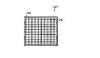
実施例4においては、液晶材料で構成された透光部を有する立体表示装置について説明する。図19は、本発明の実施例4における光学スリット部材の構成を示す模式的な平面図である。図19に示すように、本実施例の光学スリット部材1022は、対向配置された1対の基板の間に液晶層が挟持された形成された液晶パネル700によって構成されている。そして、液晶パネル700は、複数の単位セル701がマトリクス状に配列された構成を有する。この場合、単位セル701の各々が光学スリット部材1022の透光部に相当する。 In Example 4, a stereoscopic display device having a light-transmitting portion made of a liquid crystal material will be described. FIG. 19 is a schematic plan view showing the configuration of the optical slit member in Embodiment 4 of the present invention. As shown in FIG. 19, the
液晶パネル700の各単位セル701は、常時は透光不可能であるように液晶層の偏光性が設定されている。そして、所定時に液晶層の偏光性を変化させることにより、透光可能となる。ここでは、透光可能な単位セル701を開状態とし、透光不可能な単位セル701を閉状態とする。液晶パネル700では、実施例1の場合と同様、図9のステップS104における立体表示の際、高速で更新される表示パネル101(図8参照)の画像に同期して単位セル701の透光性を変化させる必要がある。したがって、光学スリット部材1022を構成する液晶パネル700は、高速応答が可能な液晶材料、例えば強誘電性液晶材料によって構成される。 In each
液晶パネル700の各単位セル701における偏光性制御動作は、図8の信号発生器103から出力される制御信号により制御されており、単位セル701毎にそれぞれ独立して偏光性が制御される。ここでは、実施例1の場合と同様、図8の信号発生器103が、記憶部1033(図8参照)から取り出された画像データが立体画像のデータおよび平面画像のデータのいずれであるかを判別するとともに、その判別結果に応じて、立体表示または平面表示に対応する制御信号が生成されて光制御パネル102(図8参照)に出力される。そして、この制御信号に基づいて光学スリットドライバ1023を制御することにより、単位セル701毎に偏光性が制御される。その結果、単位セル701の透光性をセル毎に調整することが可能となり、各単位セル701を所望の開閉状態とすることができる。 The polarization control operation in each
次に、本実施例における表示動作について説明する。本実施例では、実施例2で前述した表示動作と同様の原理によって、図9のステップS104における立体表示と、図9のステップS106における平面表示とが行われる。すなわち、図9のステップS104における立体表示では、常時は閉状態(すなわち透光不可能)である複数の単位セル701が図17(a)〜(h)に示すように逐次選択的に開状態(すなわち透光可能)となり、光学スリット部材1022における透光部(すなわち単位セル701)の透光量がT1となる。それにより、実施例2の場合と同様、MPS−IP方式により立体表示が実現され、背景11と球体12とから構成された図1の立体画像10が得られる。 Next, the display operation in the present embodiment will be described. In the present embodiment, the stereoscopic display in step S104 in FIG. 9 and the flat display in step S106 in FIG. 9 are performed based on the same principle as the display operation described in the second embodiment. That is, in the three-dimensional display in step S104 of FIG. 9, a plurality of
一方、図9のステップS106における平面表示では、単位セル701が図17(i)に示すように全て開状態(すなわち透光可能)となり、光学スリット部材1022における透光部(すなわち単位セル701)の透光量が、立体表示の場合の透光量T1よりも大きいT2となる。それにより、実施例2の場合と同様、平面表示が実現されて図1の背景11が得られる。 On the other hand, in the flat display in step S106 of FIG. 9, all the
以上のように、本実施例の立体表示装置100では、実施例2の場合と同様、光学スリット部材1022における透光量がT1と小さい立体表示と、光学スリット部材1022における透光量がT2と大きい平面表示とが経時的に切替えられて混在した構成が実現されるので、実施例2で前述した効果と同様の効果が奏される。 As described above, in the
(実施の形態2)
図20は、本発明の実施の形態2にかかる立体表示装置における表示動作の概要を示すフローチャートである。本実施の形態の立体表示装置は、図8に示す実施の形態1の立体表示装置100と同様の構成を有しており、よって、ここでは詳細な説明を省略する。(Embodiment 2)
FIG. 20 is a flowchart illustrating an overview of a display operation in the stereoscopic display device according to the second embodiment of the present invention. The stereoscopic display device according to the present embodiment has the same configuration as that of the
まず、本実施の形態の立体表示装置における表示動作の特徴的構成の概要を説明する。前述の実施の形態1の立体表示装置100(図8参照)では、立体表示と平面表示とを経時的に切替える場合について説明したが、本実施の形態では、立体表示装置の表示面の領域毎に、立体表示と平面表示とを切替える構成を有する。 First, the outline of the characteristic configuration of the display operation in the stereoscopic display device of the present embodiment will be described. In the above-described stereoscopic display device 100 (see FIG. 8) according to the first embodiment, the case where the stereoscopic display and the flat display are switched over time has been described. However, in the present embodiment, each region of the display surface of the stereoscopic display device is displayed. Furthermore, it has a configuration for switching between stereoscopic display and planar display.
すなわち、本実施の形態では、立体表示装置の表示面の一部の領域において立体表示が行われ、かつ、この立体表示と同時に、当該表示面の残りの領域において、平面表示が行われる。ここで、立体表示装置の表示面とは、具体的には、ユーザ200(図10参照)と表示パネル101(図10参照)との間に配置された光制御パネル102(図10参照)の観察者側のパネル表面である。 That is, in the present embodiment, stereoscopic display is performed in a partial region of the display surface of the stereoscopic display device, and at the same time as the stereoscopic display, planar display is performed in the remaining region of the display surface. Here, the display surface of the stereoscopic display device specifically refers to the light control panel 102 (see FIG. 10) disposed between the user 200 (see FIG. 10) and the display panel 101 (see FIG. 10). This is the panel surface on the observer side.
以下、本実施の形態における表示動作を具体的に説明する。図20に示すように、まず、立体表示装置の電源がONされて装置が起動すると(ステップS201)、図8の信号発生器103の記憶部1033(図8参照)から図6の画像データ60a〜60dの読み出しが行われる(ステップS202)。そして、この画像データ60a〜60d(図6参照)が、表示パネル101(図8参照)に出力される。 Hereinafter, the display operation in the present embodiment will be specifically described. As shown in FIG. 20, first, when the power of the stereoscopic display device is turned on and the device is activated (step S201), the
また、読み出された画像データ60a〜60d(図6参照)の情報が図8の信号発生器103において読み取られ、信号発生器103(図8参照)の制御部1031(図8参照)が、この読み取った情報に応じて、画像データ60a〜60dの種類、すなわち、立体画像のデータであるか平面画像のデータであるかを画素単位で検出する(ステップS203)。そして、この検出結果に基づいて、各画像データ60a〜60dについて、立体画像のデータおよび平面画像のデータのいずれであるかを画素毎に判定する(ステップS204)。 Further, the information of the read
以下に、上記の判定の詳細を説明する。まず、図8の信号発生器103において読み出された図6の画像データ60a〜60dは、表示対象である図1の立体画像10の平面成分である背景11(図1参照)に対応した図6の第1方向背景画像のデータ61a〜第4方向背景画像のデータ61dと、立体成分である球体12(図1参照)に対応した図6の第1方向球体画像のデータ62a〜第4方向球体画像のデータ62dとをそれぞれ含んでいる。 Details of the above determination will be described below. First, the
ここで、立体成分である球体12(図1参照)は、図1の第1方向〜第4方向(図1中の矢印13〜16の方向)の各方向間における視差が大きく、したがって、図2〜図5の第1方向球体画像22a〜第4方向球体画像22dの間では、画像差(すなわち視差)が大きい。このことから、図6の画像データ60a〜60dでは、第1方向球体画像22a〜第4方向球体画像22d(図2〜図5参照)に対応した図6の第1方向球体画像のデータ62a〜第4方向球体画像のデータ62dのデータ間の類似度が低く、データ間の差が大きい。言い換えれば、図1の立体画像10の球体12(図1参照)に対応した第1方向球体画像のデータ62a〜第4方向球体画像のデータ62dは、視差情報を多く含むデータ、すなわち立体画像のデータである。 Here, the sphere 12 (see FIG. 1), which is a three-dimensional component, has a large parallax between the first direction to the fourth direction in FIG. 1 (directions of
一方、平面成分である背景11(図1参照)は、図1の第1方向〜第4方向(図1中の矢印13〜16の方向)の各方向間における視差が小さく、したがって、図2〜図5の第1方向背景画像21a〜第4方向背景画像21dの間では画像差(すなわち視差)が小さい。このことから、図6の画像データ60a〜60dでは、第1方向背景画像21a〜第4方向背景画像21d(図2〜図5参照)に対応した図6の第1方向背景画像のデータ61a〜第4方向背景画像のデータ61dのデータ間の類似度が高く、データ間の差が小さい。言い換えれば、図1の立体画像10の背景11(図1参照)に対応した図6の第1方向背景画像のデータ61a〜第4方向背景画像のデータ61dは、視差情報の少ないデータ、すなわち平面画像のデータである。 On the other hand, the background 11 (see FIG. 1), which is a plane component, has a small parallax between the first direction to the fourth direction (directions of
本実施の形態では、このような第1方向球体画像のデータ62a〜第4方向球体画像のデータ62dおよび第1方向背景画像のデータ61a〜第4方向背景画像のデータ61dの各々について、画素単位でデータ比較を行ってデータ間の類似度(言い換えれば、データ間の差分)を検出する(ステップS203)。そして、各データ62a〜62d,61a〜61dについて、視差情報を多く含む立体画像のデータであるか、または、視差情報の少ない平面画像のデータであるかを判別する(ステップS204)。 In the present embodiment, the first direction
ここでは、ステップS203において、図8の信号発生器103のタイミング生成回路1032(図8参照)に、データ間の類似度を検出するデータ差分検出回路が生成され、このデータ差分検出回路を用いて、画素単位でデータ間の類似度(データ間の差分)を検出する。そして、ステップS204では、ステップS203における検出結果に基づいて、図8の信号発生器103の制御部1031(図8参照)が、画素単位でデータの判別を行う。 Here, in step S203, a data difference detection circuit for detecting the similarity between data is generated in the timing generation circuit 1032 (see FIG. 8) of the signal generator 103 in FIG. 8, and this data difference detection circuit is used. The similarity between data (difference between data) is detected in pixel units. In step S204, based on the detection result in step S203, the control unit 1031 (see FIG. 8) of the signal generator 103 in FIG. 8 determines data in units of pixels.
ここでは、制御部1031(図8参照)が、ステップS203において得られた各画素の検出値を、予め設けられた基準値と比較する。そして、ステップS204において、当該基準値よりも検出値が高ければ立体画像のデータであると判定し、一方、検出値が当該基準値以下であれば平面画像のデータであると判定する。それにより、各データ62a〜62d,61a〜61dについて、画素毎にデータの判定が行われる。 Here, the control unit 1031 (see FIG. 8) compares the detection value of each pixel obtained in step S203 with a reference value provided in advance. In step S204, if the detected value is higher than the reference value, it is determined that the image is stereoscopic image data. On the other hand, if the detected value is equal to or less than the reference value, it is determined that the data is planar image data. Thereby, data determination is performed for each pixel for each of the
例えば、図1の立体画像10の立体成分である球体12(図1参照)に対応する第1方向球体画像のデータ62a〜第4方向球体画像のデータ62dでは、検出されるデータ間の類似度が大きく、よって、図8の信号発生器103の制御部1031(図8参照)は、第1方向球体画像のデータ62a〜第4方向球体画像のデータ62dを、立体画像のデータであると判定する(ステップS204:Yes)。 For example, in the first direction
そして、この判定結果にしたがい、図8の信号発生器103において、立体表示のための各種制御信号が生成され、これらの制御信号が表示パネル101および光制御パネル102(ともに図8参照)にそれぞれ出力される。そして、各制御信号が入力された表示パネル101および光制御パネル102(ともに図8参照)では、第1方向球体画像のデータ62a〜第4方向球体画像のデータ62dに基づく表示が行われる領域において、立体体表示が行われる。 Then, according to the determination result, the signal generator 103 in FIG. 8 generates various control signals for stereoscopic display, and these control signals are respectively sent to the
具体的に、光制御パネル102(図8参照)では、図8の信号発生器103から出力された制御信号に基づいて、光学スリットドライバ1023(図8参照)が光学スリット部材1022(図8参照)を駆動させ、それにより、光学スリット部材1022(図8参照)に、透光部である光学スリット1021(図8参照)を適宜形成する。それにより、第1方向球体画像のデータ62a〜第4方向球体画像のデータ62dに基づく表示に対応する光制御パネル102(図8参照)の領域において、透光部(すなわち図8の光学スリット1021)の透光量がT1に調整される(ステップS205)。 Specifically, in the light control panel 102 (see FIG. 8), the optical slit driver 1023 (see FIG. 8) is replaced with the optical slit member 1022 (see FIG. 8) based on the control signal output from the signal generator 103 in FIG. ) Is thereby driven, and an optical slit 1021 (see FIG. 8), which is a light transmitting portion, is appropriately formed in the optical slit member 1022 (see FIG. 8). Accordingly, in the region of the light control panel 102 (see FIG. 8) corresponding to the display based on the first direction
このようにして光制御パネル102(図8参照)に形成された光学スリット1021(図8参照)を介して、表示パネル101(図8参照)に逐次表示される図2〜図5の第1方向球体画像22a〜第4方向球体画像22dを観察することにより、図1の立体画像10の球体12(図1参照)が立体表示される(図20のステップS206)。 The first display in FIGS. 2 to 5 is sequentially displayed on the display panel 101 (see FIG. 8) through the optical slit 1021 (see FIG. 8) formed in the light control panel 102 (see FIG. 8). By observing the
一方、図1の立体画像10の平面成分である背景11(図1参照)に対応する第1方向背景画像のデータ61a〜第4方向背景画像のデータ61dでは、検出されるデータ間の類似度が小さく、よって、図8の信号発生器103の制御部1031(図8参照)は、第1方向背景画像のデータ61a〜第4方向背景画像のデータ61dを、平面画像のデータであると判定する(ステップS204:No)。 On the other hand, in the first direction
そして、この判定結果にしたがい、図8の信号発生器103において、平面表示のための各種制御信号が生成され、これらの制御信号が表示パネル101および光制御パネル102(ともに図8参照)にそれぞれ出力される。そして、各制御信号が入力された表示パネル101および光制御パネル102(ともに図8参照)では、第1方向背景画像のデータ61a〜第4方向背景画像のデータ61dに基づく表示が行われる領域において、平面表示が行われる。 Then, according to this determination result, the signal generator 103 in FIG. 8 generates various control signals for flat display, and these control signals are respectively sent to the
具体的に、光制御パネル102(図8参照)では、図8の信号発生器103から出力された制御信号に基づいて、光学スリットドライバ1023(図8参照)が光学スリット部材1022(図8参照)を駆動させ、それにより、光学スリット部材1022(図8参照)に、透光部である光学スリット1021(図8参照)を適宜形成する。それにより、第1方向背景画像のデータ61a〜第4方向背景画像のデータ61dに基づく表示に対応する光制御パネル102(図8参照)の領域において、透光部(すなわち図8の光学スリット1021)の透光量が、前述の立体表示を行う領域の透光量T1よりも大きいT2に調整される(ステップS207)。 Specifically, in the light control panel 102 (see FIG. 8), the optical slit driver 1023 (see FIG. 8) is replaced with the optical slit member 1022 (see FIG. 8) based on the control signal output from the signal generator 103 in FIG. ) Is thereby driven, and an optical slit 1021 (see FIG. 8), which is a light transmitting portion, is appropriately formed in the optical slit member 1022 (see FIG. 8). Accordingly, in the region of the light control panel 102 (see FIG. 8) corresponding to the display based on the first direction
このようにして光制御パネル102(図8参照)に形成された光学スリット1021(図8参照)を介して、表示パネル101(図8参照)に逐次表示される図2〜図5の第1方向背景画像22a〜第4方向背景画像22dを観察することにより、図1の立体画像10の背景11(図1参照)が平面表示される(図20のステップS208)。 The first display in FIGS. 2 to 5 is sequentially displayed on the display panel 101 (see FIG. 8) through the optical slit 1021 (see FIG. 8) formed in the light control panel 102 (see FIG. 8). By observing the
ここで、光制御パネル102(図8参照)では、かかる平面表示により背景11(図1参照)の表示が行われる領域の透光部の透光量T2が、立体表示により球体12(図1参照)の表示が行われる領域の透光部の透光量T1よりも大きいので、平面表示が行われる領域の外部観察輝度は、立体表示が行われる領域の外部観察輝度に比べて高輝度となる。 Here, in the light control panel 102 (see FIG. 8), the light transmission amount T2 of the translucent portion in the region where the background 11 (see FIG. 1) is displayed by the planar display is changed to the sphere 12 (FIG. 1). Therefore, the external observation luminance of the region where the planar display is performed is higher than the external observation luminance of the region where the stereoscopic display is performed. Become.
このように、本実施の形態では、第1方向球体画像のデータ62a〜第4方向球体画像のデータ62d(図6参照)に基づく表示が行われる領域において、立体表示を実現して図1の球体12を表示するとともに、第1方向背景画像のデータ61a〜第4方向球体画像のデータ61d(図6参照)に基づく表示が行われる領域において、平面表示を実現して図1の背景11を表示する。それにより、立体表示装置の表示面において領域毎に立体表示と平面表示とが混在する構成が実現され、このような混在の結果、目的とする図1の立体画像10が得られる(ステップS209)。 As described above, in the present embodiment, stereoscopic display is realized in a region where display is performed based on the first direction
上記の図1の立体画像10の表示の後、表示動作の終了指示が入力されたか否かの判定が行われる(ステップS210)。そして、終了指示が入力されると(ステップS210:Yes)、表示動作が終了する。一方、終了指示が入力されないと(ステップS210:No)、再びステップS202に戻って表示動作が続行される。 After the display of the
以上のように、本実施の形態の立体表示装置では、表示面の一部の領域において、光制御パネル102(図8参照)の透光部における透光量をT1とする外部観察輝度の低い立体表示が行われ、残りの領域において、光制御パネル102(図8参照)の透光部における透光量をT2とする外部観察輝度の高い平面表示が行われる。このように同一の表示面において立体表示と平面表示とが混在する本実施の形態の構成では、外部観察輝度の高い平面表示を含むことによって、表示面全体で立体表示が行われる場合に比べて全体の外部観察輝度の向上が図られる。したがって、良好な視認性で図1の立体画像10の表示を行うことが可能となる。 As described above, in the stereoscopic display device according to the present embodiment, the external observation luminance is low with T1 as the light transmission amount in the light transmission portion of the light control panel 102 (see FIG. 8) in a partial region of the display surface. Stereoscopic display is performed, and in the remaining area, planar display with high external observation luminance is performed with the light transmission amount in the light transmission part of the light control panel 102 (see FIG. 8) being T2. As described above, in the configuration of the present embodiment in which the stereoscopic display and the planar display are mixed on the same display surface, the stereoscopic display is performed on the entire display surface by including the planar display with high external observation luminance. The overall external observation luminance can be improved. Therefore, it is possible to display the
この場合、平面表示が行われる領域では、平面画像のデータであると判定された第1方向背景画像のデータ61a〜第4方向背景画像のデータ61d(図6参照)に基づいて、図1の立体画像の平面成分である背景11(図1参照)の表示が行われる。したがって、図1の立体画像10の立体成分である球体12(図1参照)は、平面表示の混在による影響を受けず、よって、球体12(図1参照)において良好な立体感を実現することが可能となる。したがって、本実施の形態の立体表示装置では、良好な表示特性と良好な視認性とが実現可能である。 In this case, in the area where the flat display is performed, based on the first direction
なお、上記においては、データの類似度を検出し、その検出結果から立体画像のデータおよび平面画像のデータのいずれであるかを判定する場合を例示したが、これ以外に、実施の形態1において前述したように、立体画像のデータおよび平面画像のデータのいずれであるかの判別情報が、予め、第1方向背景画像のデータ61a〜第4方向背景画像のデータ61dおよび第1方向球体画像のデータ62a〜第4方向球体画像のデータ62dの各々に付随した構成であってもよく、例えば、これらのデータ61a〜61d,62a〜62dの各々のヘッダファイルに、この判別情報が含まれていてもよい。かかる構成とすれば、前述のようなデータの類似度検出が不要となるので、データ差分検出回路を図8の信号発生器103のタイミング生成回路1032(図8参照)に生成する必要がない。したがって、システムコストの低減化が図られるとともに、より高速での表示動作が可能となる。 In the above, the case of detecting the similarity of data and determining whether the data is a stereoscopic image data or a planar image data from the detection result is exemplified. As described above, the discrimination information as to whether the data is a stereoscopic image data or a planar image data is preliminarily stored in the first direction
さらに、図8の光制御パネル102の透光部に相当する光学スリット1021(図8参照)の開口情報、すなわち、図8の光学スリット1021における透光量が立体表示に対応するT1および平面表示に対応するT2のいずれになるよう開口調整するかという情報が、第1方向背景画像のデータ61a〜第4方向背景画像のデータ61dおよび第1方向球体画像のデータ62a〜第4方向球体画像のデータ62dの各々に予め含まれていることが好ましい。それにより、これらの各データ61a〜61d,62a〜62dの読み出しが高速で行われても、読み出し動作と連動して光制御パネル102(図8参照)の透光部の開口調整を高速で行うことが可能となる。 Further, the opening information of the optical slit 1021 (see FIG. 8) corresponding to the light transmitting portion of the
また、上記においては図6の画像データ60を用いる場合について説明したが、図7の画像データ60を用いてもよい。図7の画像データ60を用いる場合には、図1の立体画像10の背景11(図1参照)に対応するデータが、第1方向背景画像のデータ61a(図7参照)のみである。したがって、この場合には、平面表示を行う領域において、立体表示を行う領域のような画像更新を行わずに、図2の第1方向背景画像21aを表示する。 In the above description, the case of using the image data 60 of FIG. 6 has been described. However, the image data 60 of FIG. 7 may be used. When the image data 60 in FIG. 7 is used, the data corresponding to the background 11 (see FIG. 1) of the
ところで、同一の表示面において領域毎に高輝度の平面表示と低輝度の立体表示とを行う本実施の形態の構成では、領域毎の外部観察輝度の差が大きすぎると、表示面における外部観察輝度が著しく不均一となり、ユーザに違和感を与えたり、表示特性や視認性を劣化させる可能性がある。そこで、このような問題を回避するために、平面表示を行う領域と立体表示を行う領域との外部観察輝度の差が大きくなりすぎないよう、必要に応じて各領域の表示パネル101(図8参照)の発光輝度を調整することが好ましい。例えば、平面表示を行う領域における発光輝度が立体表示を行う領域における発光輝度よりも低くなるか、または、立体表示を行う領域における発光輝度が平面表示を行う領域における発光輝度よりも高くなるように、表示パネル101(図8参照)の発光輝度を適宜調整する。 By the way, in the configuration of the present embodiment in which high luminance planar display and low luminance stereoscopic display are performed for each region on the same display surface, if the difference in external observation luminance for each region is too large, external observation on the display surface is performed. Luminance becomes extremely uneven, which may give the user a sense of incongruity and may deteriorate display characteristics and visibility. Therefore, in order to avoid such a problem, the
次に、本実施の形態の具体的な態様を、以下の実施例を参照して説明する。図21は、本発明の実施例5における立体表示装置における表示動作の原理を説明するための模式図である。図21に示すように、本実施例の立体表示装置100は、前述の実施例1と同様、光制御パネル102の光学スリット部材1022が、シャッタ板400(図12参照)を備えた構成を有している。 Next, specific modes of the present embodiment will be described with reference to the following examples. FIG. 21 is a schematic diagram for explaining the principle of the display operation in the stereoscopic display device according to Embodiment 5 of the present invention. As shown in FIG. 21, the
本実施例の立体表示装置100では、平面画像のデータである図6の第1方向背景画像のデータ61a〜第4方向背景画像のデータ61dに基づく表示が行われる領域210において、シャッタ板400が図14に示す開状態となり、よって、当該領域の全体に光学スリット1021が形成される。この場合、領域210における光制御パネル102の透光量はT2であり、後述の立体表示が行われる領域211の透光量T1よりも大きい(図20のステップS207)。このように透光量が大きい領域210では、目的とする立体画像10の平面成分である背景11が平面表示される(図20のステップS208)。 In the
一方、立体画像のデータである図6の第1方向球体画像のデータ62a〜第4方向球体画像のデータ62dに基づく表示が行われる領域211では、図12および図13に示すようにシャッタ板400が逐次選択的に開状態となり、逐次選択的に光学スリット1021が形成される。この場合、領域211における光制御パネル102の透光量はT1であり、平面表示が行われる領域210の透光量T2よりも小さい(図20のステップS205)。このように透光量が小さい領域210では、MPS−IP方式により立体表示が実現され、それにより、目的とする立体画像10の立体成分である球体12が得られる(図20のステップS206)。 On the other hand, in the
以上のように、本実施例の立体表示装置100では、領域210において平面表示が行われるとともに、領域211において立体表示が行われ、その結果、背景11と球体12とから構成される立体画像10が得られる(図20のステップS209)。このような立体表示装置100では、立体表示と平面表示とが経時的に切替えられる実施例1の場合において前述した効果と同様の効果が得られる。 As described above, in the
本発明の実施例6における立体表示装置は、実施例2の立体表示装置と同様、図15に示すピンホール501を備えた光学スリット部材1022を備える。ここでは、光学スリット部材1022の各ピンホール501が、表示パネル102(図8参照)の各画素に対応しており、画素単位でピンホール501の開閉を制御することが可能である。 A stereoscopic display device according to Embodiment 6 of the present invention includes an
本実施例の立体表示装置では、平面画像のデータである図6の第1方向背景画像のデータ61a〜第4方向背景画像のデータ61dに基づく表示が行われる画素に対応したピンホール501(図15参照)と、立体画像のデータである図6の第1方向球体画像のデータ62a〜第4方向球体画像のデータ62dに基づく表示が行われる画素に対応したピンホール501(図15参照)とで、異なる開閉動作が行われる。 In the stereoscopic display device of the present embodiment, the
このようなピンホール501(図15参照)の開閉動作の結果、平面画像のデータである図6の第1方向背景画像のデータ61a〜第4方向背景画像のデータ61dに基づく表示が行われる領域では、ピンホール501(図15参照)が、図17(i)に示す開口状態となる。この場合、当該領域における光制御パネル102(図8参照)の透光量はT2であり、後述の立体表示が行われる領域の透光量T1よりも大きい(図20のステップS207)。このように透光量が大きい領域では、目的とする立体画像10(図1参照)の平面成分である背景11(図1参照)が平面表示される(図20のステップS208)。 As a result of the opening / closing operation of the pinhole 501 (see FIG. 15), an area in which display is performed based on the first direction
一方、立体画像のデータである図6の第1方向球体画像のデータ62a〜第4方向球体画像のデータ62dに基づく表示が行われる領域では、ピンホール501(図15参照)が、図17(a)〜(h)に示すように、逐次選択的に開状態となる。そして、このようなピンホール501(図15参照)の開口状態が実現される領域では、光制御パネル102の透光量がT1であり、平面表示が行われる領域の透光量T2よりも小さい(図20のステップS205)。このように透光量が小さい領域では、MPS−IP方式により立体表示が実現され、それにより、目的とする立体画像10の立体成分である球体12が得られる(図20のステップS206)。 On the other hand, in the region where the display is performed based on the first direction
なお、ここではMPS−IP方式により立体表示を行う場合を説明したが、例えば、実施例3で前述した従来のIP方式により立体表示を行ってもよい。この場合、図6の第1方向球体画像のデータ62a〜第4方向球体画像のデータ62dに基づく表示が行われる領域では、ピンホール501(図15参照)が、図18(a)〜(d)に示す開口状態となり、当該領域における光制御パネル102の透光量がT1となる。 Here, the case where the stereoscopic display is performed by the MPS-IP method has been described, but the stereoscopic display may be performed by the conventional IP method described in the third embodiment, for example. In this case, in a region where display is performed based on the first direction
以上のように、本実施例の立体表示装置では、実施例5の場合と同様に、領域毎に平面表示と立体表示とを切替えて行うことが可能となり、両表示を混在させる構成が実現される。したがって、本実施例においても、実施例5の場合において前述した効果と同様の効果が得られる。 As described above, in the stereoscopic display device according to the present embodiment, as in the case of the fifth embodiment, it is possible to switch between planar display and stereoscopic display for each region, and a configuration in which both displays are mixed is realized. The Therefore, also in the present embodiment, the same effects as those described above in the case of the fifth embodiment can be obtained.
本発明の実施例7における立体表示装置は、実施例4の立体表示装置と同様、図19に示す液晶パネル700を備えた光学スリット部材1022を備える。ここでは、液晶パネル700の各単位セル701が、表示パネル102(図8参照)の各画素に対応しており、画素単位で単位セル701の偏光性を制御して透光量を制御することが可能である。 The stereoscopic display device according to the seventh embodiment of the present invention includes the
本実施例の立体表示装置では、実施例6の場合と同様、平面画像のデータである図6の第1方向背景画像のデータ61a〜第4方向背景画像のデータ61dに基づく表示が行われる画素に対応した単位セル701(図19参照)と、立体画像のデータである図6の第1方向球体画像のデータ62a〜第4方向球体画像のデータ62dに基づく表示が行われる画素に対応した単位セル701(図15参照)とで、それぞれ異なる偏光性制御動作が行われ、それにより、各単位セル701(図15参照)が異なる透光量に調整される。 In the stereoscopic display device according to the present embodiment, as in the case of the sixth embodiment, pixels on which display is performed based on the first-direction
このような単位セル701(図19参照)の偏光性制御動作の結果、平面画像のデータである図6の第1方向背景画像のデータ61a〜第4方向背景画像のデータ61dに基づく表示が行われる領域では、実施例6の場合と同様、単位セル701(図19参照)が、図17(i)に示す透光状態となり、当該領域における光制御パネル102(図8参照)の透光量がT2となる(図20のステップS207参照)。それにより、かかる領域では、図1の背景11の平面表示が行われる(図20のステップS208参照)。一方、立体画像のデータである図6の第1方向球体画像のデータ62a〜第4方向球体画像のデータ62dに基づく表示が行われる領域では、単位セル701(図19参照)が、図17(a)〜(h)に示す透光状態となり、当該領域における光制御パネル102(図8参照)の透光量がT1となる(図20のステップS205参照)。それにより、かかる領域では、図1の球体12の平面表示が行われる(図20のステップS206参照)。 As a result of the polarization control operation of the unit cell 701 (see FIG. 19), display based on the first direction
以上のように、本実施例の立体表示装置では、実施例6の場合と同様に、領域毎に平面表示と立体表示とを切替えて行うことが可能となり、両表示を混在させる構成が実現される。したがって、本実施例においても、実施例6の場合において前述した効果と同様の効果が得られる。 As described above, in the stereoscopic display device according to the present embodiment, as in the case of the sixth embodiment, it is possible to switch between planar display and stereoscopic display for each region, and a configuration in which both displays are mixed is realized. The Therefore, also in the present embodiment, the same effects as those described above in the case of the sixth embodiment can be obtained.
なお、上記の実施の形態1および実施の形態2は、本発明の例示であり、本発明が上記構成に限定されるものではない。例えば、実施の形態1および実施の形態2においては、立体画像のデータおよび平面画像のデータのいずれであるかを判別するための判別情報が画像データに含まれる場合を例示したが、当該判別情報が、画像データとは別に図8の信号発生器103の記憶部1033(図8参照)に記憶された構成であってもよい。また、光制御パネル102(図8参照)の透光部の開口情報が、画像データとは別に図8の信号発生器103の記憶部1033(図8参照)に記憶された構成であってもよい。 In addition, said
本発明は、IP方式以外の立体表示方式、例えばパララックスステレオグラム式等の立体表示装置についても適用可能である。さらに、本発明において、光制御パネル102が観察者と表示パネル101との間に配置されるのであれば、光制御パネル102の配置位置は、特には限定されない。例えば、光制御パネル102と表示パネル101とが一体的に構成されてもよく、あるいは、光制御パネル102が表示パネル101と距離をあけて配置された構成や、光制御パネル102が表示パネル101から独立して配置された構成であってもよい。 The present invention can also be applied to a stereoscopic display system other than the IP system, for example, a stereoscopic display device such as a parallax stereogram system. Furthermore, in the present invention, as long as the
このような本発明は、種々の用途に利用可能であり、一例として、携帯電話やパソコン等の情報機器端末や、ゲーム機器等への利用があげられる。 The present invention as described above can be used for various purposes, and examples thereof include use in information equipment terminals such as mobile phones and personal computers, game machines, and the like.
10 立体画像
11 背景
12 球体
20a〜20d 構成要素平面画像
60a〜60d 画像データ
100 立体表示装置
101 表示パネル
102 光制御パネル
103 信号発生器
200 ユーザ
210,211 領域
400 シャッタ板
401 支軸
402 枠材
500 パネル基材
501 ピンホール
600 ピンホールシャッタ
700 液晶パネル
701 単位セル
1021 光学スリット
1022 光学スリット部材
1023 光学スリットドライバDESCRIPTION OF
Claims (7)
Translated fromJapanese入力された画像データに基づいて、目的の立体画像の構成要素である複数の平面画像を表示する表示手段と、
前記表示手段と観察者との間に配置され、前記表示手段からの透光量の調整を行う光制御手段とを備え、
前記光制御手段は、非透光性の基体と、前記基体に形成された前記平面画像の可視領域である複数の透光部と、前記透光部の面積を調整して前記透光量の調整を行う透光部調整手段とを有し、
前記透光部の透光量が第1の量に調整された立体表示と、前記透光部の透光量が前記第1の量よりも多い第2の量に調整された平面表示とを周波数15Hz以上の速さで切替えて、前記目的の立体画像を表示することを特徴とする立体表示装置。A stereoscopic display device that performs stereoscopic display by displaying a planar image that gives binocular parallax,
Display means for displaying a plurality of planar images, which are constituent elements of the target stereoscopic image, based on the input image data;
A light control means that is arranged between the display means and the observer and adjusts the amount of light transmitted from the display means;
The light control means adjusts an area of the light transmitting portion by adjusting an area of the light transmitting portion, a plurality of light transmitting portions which are visible regions of the planar image formed on the substrate, and a light transmitting portion. A translucent part adjusting means for adjusting,
Three-dimensional display in which the light transmission amount of the light transmission part is adjusted to a first amount, and a flat display in which the light transmission amount of the light transmission part is adjusted to a second amount larger than the first amount. A stereoscopic display device, wherein the target stereoscopic image is displayed by switching at a frequency of 15 Hz or more.
前記光制御手段は、所定の前記透光部が透光可能となるとともにこれ以外の前記透光部を透光不可能とし、かつ、透光可能な前記透光部の位置を逐次選択的に変化させ、
前記表示手段に表示する前記平面画像を前記透光部の位置の変化と同期して更新し、かつ、選択された前記透光部に対応する前記平面画像を表示して前記立体表示を行うことを特徴とする請求項1に記載の立体表示装置。The display means selectively displays each of the plurality of planar images sequentially,
The light control means allows the predetermined light-transmitting portion to transmit light, makes the other light-transmitting portions impossible to transmit light, and sequentially selects the positions of the light-transmitting portions capable of transmitting light. Change
Updating the planar image displayed on the display means in synchronization with a change in the position of the translucent part, and displaying the planar image corresponding to the selected translucent part to perform the stereoscopic display. The stereoscopic display device according to claim 1, wherein:
前記透光部調整手段は、前記判別手段の判別結果に応じて前記透光部の面積を調整することを特徴とする請求項1に記載の立体表示装置。 The stereoscopic display device according to claim 1, wherein the translucent part adjusting unit adjusts an area of the translucent part according to a determination result of the determining unit.
前記判別手段は、前記判別情報に基づいて、前記立体表示および前記平面表示のいずれを行うかを判別することを特徴とする請求項4に記載の立体表示装置。 The stereoscopic display device according to claim 4, wherein the determination unit determines whether to perform the stereoscopic display or the flat display based on the determination information.
Applications Claiming Priority (3)
| Application Number | Priority Date | Filing Date | Title |
|---|---|---|---|
| JP2004335183 | 2004-11-18 | ||
| JP2004335183 | 2004-11-18 | ||
| PCT/JP2005/020842WO2006054518A1 (en) | 2004-11-18 | 2005-11-14 | 3d display device |
Publications (2)
| Publication Number | Publication Date |
|---|---|
| JPWO2006054518A1 JPWO2006054518A1 (en) | 2008-05-29 |
| JP4568731B2true JP4568731B2 (en) | 2010-10-27 |
Family
ID=36407061
Family Applications (1)
| Application Number | Title | Priority Date | Filing Date |
|---|---|---|---|
| JP2006545010AExpired - Fee RelatedJP4568731B2 (en) | 2004-11-18 | 2005-11-14 | 3D display device |
Country Status (4)
| Country | Link |
|---|---|
| US (1) | US7796332B2 (en) |
| JP (1) | JP4568731B2 (en) |
| CN (1) | CN100545702C (en) |
| WO (1) | WO2006054518A1 (en) |
Families Citing this family (19)
| Publication number | Priority date | Publication date | Assignee | Title |
|---|---|---|---|---|
| KR100846707B1 (en)* | 2007-02-27 | 2008-07-16 | 삼성에스디아이 주식회사 | Electronic imaging equipment |
| KR100839429B1 (en)* | 2007-04-17 | 2008-06-19 | 삼성에스디아이 주식회사 | Electronic imaging equipment and its driving method |
| WO2009105544A2 (en)* | 2008-02-19 | 2009-08-27 | The Board Of Trustees Of The University Of Illinois | Large format high resolution interactive display |
| JP2010169777A (en)* | 2009-01-21 | 2010-08-05 | Sony Corp | Image processing device, image processing method and program |
| JP2011211381A (en)* | 2010-03-29 | 2011-10-20 | Fujifilm Corp | Stereoscopic imaging apparatus |
| JP5659589B2 (en)* | 2010-07-13 | 2015-01-28 | 株式会社ニコン | Display device and control method |
| WO2012056692A1 (en)* | 2010-10-28 | 2012-05-03 | 富士フイルム株式会社 | 3d image display device and 3d image display method |
| US9137522B2 (en)* | 2011-07-11 | 2015-09-15 | Realtek Semiconductor Corp. | Device and method for 3-D display control |
| US9513486B2 (en) | 2011-10-24 | 2016-12-06 | Asukanet Company, Ltd. | Optical imaging apparatus |
| WO2013129063A1 (en) | 2012-02-28 | 2013-09-06 | 株式会社アスカネット | Three-dimensional image forming system and method therefor |
| JP6090305B2 (en) | 2012-03-30 | 2017-03-08 | 富士通株式会社 | Determination apparatus, determination program, and determination method |
| US20150234099A1 (en)* | 2012-11-08 | 2015-08-20 | Asukanet Company, Ltd. | Method for producing light control panel |
| TWI472803B (en)* | 2012-12-28 | 2015-02-11 | Delta Electronics Inc | Virtual image displaying system |
| WO2014136140A1 (en)* | 2013-03-05 | 2014-09-12 | パナソニック株式会社 | Video processing device and video processing method |
| JP2014175813A (en)* | 2013-03-08 | 2014-09-22 | Fa System Engineering Co Ltd | Stereoscopic video display method and device |
| EA029852B1 (en)* | 2013-03-25 | 2018-05-31 | Джозеф Джегер | Vibrating grid based 3d space visualization device |
| IL313875A (en)* | 2013-11-27 | 2024-08-01 | Magic Leap Inc | Virtual and augmented reality systems and methods |
| JP7526651B2 (en)* | 2020-12-04 | 2024-08-01 | 日本放送協会 | 3D image display device |
| CN114660827A (en)* | 2020-12-22 | 2022-06-24 | 群创光电股份有限公司 | Electronic device and display method thereof |
Citations (2)
| Publication number | Priority date | Publication date | Assignee | Title |
|---|---|---|---|---|
| JPH06160770A (en)* | 1992-11-25 | 1994-06-07 | Nittetsu Eretsukusu:Kk | Three-dimensional stereoscopic picture display device |
| JPH0973049A (en)* | 1995-06-29 | 1997-03-18 | Canon Inc | Image display method and image display apparatus using the same |
Family Cites Families (5)
| Publication number | Priority date | Publication date | Assignee | Title |
|---|---|---|---|---|
| JP2001330713A (en)* | 2000-05-22 | 2001-11-30 | Namco Ltd | Filters and electronics |
| KR20040026693A (en)* | 2001-07-27 | 2004-03-31 | 코닌클리케 필립스 일렉트로닉스 엔.브이. | Autostereoscopic image display with observer tracking system |
| CN1243272C (en)* | 2002-12-10 | 2006-02-22 | 财团法人工业技术研究院 | 2D-3D switching autostereoscopic display device |
| US7221332B2 (en)* | 2003-12-19 | 2007-05-22 | Eastman Kodak Company | 3D stereo OLED display |
| TWI264600B (en)* | 2005-02-03 | 2006-10-21 | Au Optronics Corp | 2D/3D display and method for forming 3D images |
- 2005
- 2005-11-14JPJP2006545010Apatent/JP4568731B2/ennot_activeExpired - Fee Related
- 2005-11-14WOPCT/JP2005/020842patent/WO2006054518A1/enactiveApplication Filing
- 2005-11-14USUS11/719,698patent/US7796332B2/ennot_activeExpired - Fee Related
- 2005-11-14CNCNB2005800396493Apatent/CN100545702C/ennot_activeExpired - Fee Related
Patent Citations (2)
| Publication number | Priority date | Publication date | Assignee | Title |
|---|---|---|---|---|
| JPH06160770A (en)* | 1992-11-25 | 1994-06-07 | Nittetsu Eretsukusu:Kk | Three-dimensional stereoscopic picture display device |
| JPH0973049A (en)* | 1995-06-29 | 1997-03-18 | Canon Inc | Image display method and image display apparatus using the same |
Also Published As
| Publication number | Publication date |
|---|---|
| US7796332B2 (en) | 2010-09-14 |
| JPWO2006054518A1 (en) | 2008-05-29 |
| CN100545702C (en) | 2009-09-30 |
| WO2006054518A1 (en) | 2006-05-26 |
| CN101061414A (en) | 2007-10-24 |
| US20080285127A1 (en) | 2008-11-20 |
Similar Documents
| Publication | Publication Date | Title |
|---|---|---|
| JP4568731B2 (en) | 3D display device | |
| JP4332158B2 (en) | Backlight module and 2D / 3D display device using the backlight module | |
| TWI426300B (en) | Display device | |
| EP2053867B1 (en) | Parallax barrier device and electronic display device | |
| CN1784022B (en) | Spacer device and stereoscopic image display using the same | |
| JP5264482B2 (en) | Combined single / multiple view display | |
| KR100678551B1 (en) | Auto stereoscopic display | |
| KR20070043147A (en) | Stereoscopic Display and Driving Method | |
| JP2009053391A (en) | Display element | |
| JP5093690B2 (en) | Display device and display method | |
| JP2004258631A (en) | 3D image display device | |
| KR20090058428A (en) | 3D video display device | |
| JP2010276928A (en) | 3D image display device | |
| TW201527799A (en) | Display device | |
| KR20060124143A (en) | Display device capable of selective display of 2D and 3D images | |
| WO2012093692A1 (en) | Liquid crystal display device | |
| KR101183397B1 (en) | Liquid Crystal Display Device Controlable View-angle and Driving Method thereof | |
| WO2006054516A1 (en) | Stereoscopic display apparatus | |
| JP4773714B2 (en) | 3D display device | |
| JP2004297607A (en) | Light shielding barrier unit and three-dimensional video display device using the same | |
| JP2007228390A (en) | Image display apparatus and image processing method | |
| JP4407176B2 (en) | Display device | |
| JP4873069B2 (en) | Display device | |
| JP2005045496A (en) | Stereoscopic image display device | |
| JP6349677B2 (en) | Scanning line driving circuit, electro-optical device driving method, electro-optical device, and electronic apparatus |
Legal Events
| Date | Code | Title | Description |
|---|---|---|---|
| A131 | Notification of reasons for refusal | Free format text:JAPANESE INTERMEDIATE CODE: A131 Effective date:20100615 | |
| A521 | Request for written amendment filed | Free format text:JAPANESE INTERMEDIATE CODE: A523 Effective date:20100713 | |
| TRDD | Decision of grant or rejection written | ||
| A01 | Written decision to grant a patent or to grant a registration (utility model) | Free format text:JAPANESE INTERMEDIATE CODE: A01 Effective date:20100803 | |
| A01 | Written decision to grant a patent or to grant a registration (utility model) | Free format text:JAPANESE INTERMEDIATE CODE: A01 | |
| A61 | First payment of annual fees (during grant procedure) | Free format text:JAPANESE INTERMEDIATE CODE: A61 Effective date:20100809 | |
| R150 | Certificate of patent or registration of utility model | Free format text:JAPANESE INTERMEDIATE CODE: R150 | |
| FPAY | Renewal fee payment (event date is renewal date of database) | Free format text:PAYMENT UNTIL: 20130813 Year of fee payment:3 | |
| LAPS | Cancellation because of no payment of annual fees |