JP4566943B2 - Charger - Google Patents
ChargerDownload PDFInfo
- Publication number
- JP4566943B2 JP4566943B2JP2006121964AJP2006121964AJP4566943B2JP 4566943 B2JP4566943 B2JP 4566943B2JP 2006121964 AJP2006121964 AJP 2006121964AJP 2006121964 AJP2006121964 AJP 2006121964AJP 4566943 B2JP4566943 B2JP 4566943B2
- Authority
- JP
- Japan
- Prior art keywords
- charging
- sound
- battery
- data
- connector
- Prior art date
- Legal status (The legal status is an assumption and is not a legal conclusion. Google has not performed a legal analysis and makes no representation as to the accuracy of the status listed.)
- Active
Links
Images


Classifications
- H—ELECTRICITY
- H02—GENERATION; CONVERSION OR DISTRIBUTION OF ELECTRIC POWER
- H02J—CIRCUIT ARRANGEMENTS OR SYSTEMS FOR SUPPLYING OR DISTRIBUTING ELECTRIC POWER; SYSTEMS FOR STORING ELECTRIC ENERGY
- H02J7/00—Circuit arrangements for charging or depolarising batteries or for supplying loads from batteries
- H02J7/0047—Circuit arrangements for charging or depolarising batteries or for supplying loads from batteries with monitoring or indicating devices or circuits
- H02J7/0048—Detection of remaining charge capacity or state of charge [SOC]
- H02J7/0049—Detection of fully charged condition
Landscapes
- Engineering & Computer Science (AREA)
- Power Engineering (AREA)
- Charge And Discharge Circuits For Batteries Or The Like (AREA)
- Secondary Cells (AREA)
Description
Translated fromJapanese本発明は、電動工具のバッテリを充電するための充電装置に関する。 The present invention relates to a charging device for charging a battery of an electric tool.
電動工具に関する上記した充電装置としては、例えば、特許文献1に示すものが知られている。
特許文献1に係る充電装置は、音声発生器を備えており、バッテリの充電が完了したときに、音声を発するように構成されている。このため、使用者が充電装置から離れて作業をしているときでも、音声によりバッテリの充電完了を認識できるようになる。As the above-described charging device related to the electric power tool, for example, the one shown in Patent Document 1 is known.
The charging device according to Patent Document 1 includes a sound generator, and is configured to emit sound when charging of a battery is completed. For this reason, even when the user is working away from the charging device, the completion of charging of the battery can be recognized by voice.
しかし、現場に、同種類、あるいは類似する種類の充電装置が複数台ある場合、単に音声を発生させるだけでは、どの充電装置でバッテリの充電が完了したのか認識できなくなることがある。 However, when there are a plurality of charging devices of the same type or similar types at the site, it may not be possible to recognize which charging device has completed charging the battery by simply generating sound.
本発明は、上記問題点を解決するためになされたものであり、本発明が解決しようとする課題は、現場で同種類、あるいは類似する種類の充電装置が複数台使用されているときでも、離れた位置で特定の充電装置におけるバッテリの充電完了を認識できるようにすることである。 The present invention was made to solve the above problems, and the problem to be solved by the present invention is that even when a plurality of charging devices of the same type or similar types are used in the field, It is to be able to recognize the completion of charging of the battery in a specific charging device at a remote position.
上記した課題は、各請求項の発明によって解決される。
請求項1の発明は、バッテリ側のコネクタと電気的に接続可能に構成されている充電用コネクタと、前記バッテリ側のコネクタが前記充電用コネクタに接続されている状態で前記バッテリの充電を行なう充電手段と、複数種類の音パターンのデータを記憶できる音パターン記憶手段と、前記音パターン記憶手段に記憶されている複数種類の音パターンのデータから所定の音パターンのデータを選択する音パターン選択手段と、前記充電手段による前記バッテリの充電が完了したときに、前記音パターン選択手段により選択された所定の音パターンのデータに基づいて音を発生させる発音手段とを有する充電装置であって、 前記充電手段は、バッテリ側のコネクタが充電用コネクタに所定時間以上接続されている状態で前記バッテリの充電を開始する構成であり、音パターン選択手段は、前記バッテリの充電が開始される前に、前記充電用コネクタに対する前記バッテリ側のコネクタの接続が解除され、さらに再接続が行なわれたときに、既に選択された音パターンのデータを音パターン記憶手段に記憶されている次の音パターンのデータに切替えることを特徴とする。The above-described problems are solved by the inventions of the claims.
According to the first aspect of the present invention, a charging connector configured to be electrically connectable to a battery-side connector, and the battery is charged in a state where the battery-side connector is connected to the charging connector. A sound pattern selection unit that selects data of a predetermined sound pattern from data of a plurality of types of sound patterns stored in the sound pattern storage unit, a sound pattern storage unit that can store data of a plurality of types of sound patterns, and a charging unit And a sounding means for generating a sound based on data of a predetermined sound pattern selected by the sound pattern selection means when charging of the battery by the charging means is completed, The charging means opens the battery with the battery-side connector connected to the charging connector for a predetermined time or more. The sound pattern selection means is configured so that the connection of the battery-side connector to the charging connector is released before recharging and the reconnection is performed before charging of the battery is started. The data of the selected sound pattern is switched tothe data of the next sound pattern stored in the sound pattern storage means .
本発明によると、音パターン選択手段により複数種類の音パターンのデータ中から所定の音パターンのデータを選択することができる。このため、現場で同種類、あるいは類似する種類の充電装置が複数台使用されているときでも、他の充電装置の充電完了音と異なる音パターンを選択することが可能になる。したがって、バッテリの充電完了時に、他の充電装置の充電完了音と異なる音パターンのデータに基づき発音手段で音を発生させることにより、使用者は特定の充電装置におけるバッテリの充電完了を明確に知ることができる。
また、バッテリの充電が開始される前に、充電用コネクタに対するバッテリ側のコネクタの接続解除、及び再接続を繰り返すことで、音パターン記憶手段に記憶されている音パターンのデータを順番に選択することが可能になる。したがって、音パターンの切替え用スイッチ等を設ける必要がなく、コスト低減を図ることができる。
ここで、「音パターン」とは、メロディ、音声、ブザー音、サイレン音等、あらゆる種類の音を含むものとする。According to the present invention, it is possible to select data of a predetermined sound pattern from a plurality of types of sound pattern data by the sound pattern selection means. For this reason, even when a plurality of charging devices of the same type or similar types are used in the field, it is possible to select a sound pattern different from the charging completion sound of other charging devices. Therefore, when the charging of the battery is completed, the user can clearly know the completion of charging of the battery in the specific charging device by generating a sound with the sound generation means based on the data of the sound pattern different from the charging completion sound of the other charging device. be able to.
Further, before the battery is started to be charged, sound pattern data stored in the sound pattern storage means is sequentially selected by repeatedly disconnecting and reconnecting the battery-side connector to the charging connector. It becomes possible. Therefore, it is not necessary to provide a switch for switching sound patterns, and the cost can be reduced.
Here, the “sound pattern” includes all kinds of sounds such as a melody, a voice, a buzzer sound, and a siren sound.
請求項2の発明によると、発音手段は、音パターン選択手段が音パターンのデータを選択する際に、選択された音パターンのデータに基づく音を充電完了時よりも小さい音で発生させることを特徴とする。
このため、音を聞きながら音パターンを選択できるようになり、正確に音パターンの選択が行なえる。
請求項3の発明によると、発音手段は、音の発生素子に印加される電圧を変化させることで、音の大きさを変化させられるように構成されていることを特徴とする。According to the invention of
Therefore, it becomes possible to select a sound pattern while listening to the sound, and the sound pattern can be selected accurately.
According to athird aspect of the present invention, the sound generation means is configured to change the volume of the sound by changing the voltage applied to the sound generating element.
請求項4の発明によると、音パターン記憶手段は、パソコンによってメロディのデータを書き込み可能なように構成されていることを特徴とする。
このため、例えば、パソコンによりインターネットを利用して曲をダウンロードすることにより、使用者の好みに応じた音パターンを得ることができ、他の充電装置と明確に区別できるようになる。
請求項5の発明によると、充電手段によるバッテリの充電が完了したときに、発光素子を発光させる発光手段を備えていることを特徴とする。
このため、バッテリの充電完了がさらに認識し易くなる。
請求項6の発明によると、充電手段によるバッテリの充電が完了したときに、通信端末器で受信可能な充電完了信号を発信する発信手段を備えていることを特徴とする。
このため、現場から遠く離れた場所でも、例えば、携帯電話等で充電完了を知ることができる。
According to afourth aspect of the present invention, the sound pattern storage means is configured so that melody data can be written by a personal computer.
For this reason, for example, by downloading a song using the Internet using a personal computer, a sound pattern according to the user's preference can be obtained and can be clearly distinguished from other charging devices.
According to afifth aspect of the present invention, the light emitting device for emitting light from the light emitting element when the charging of the battery by the charging device is completed is provided.
For this reason, it becomes easier to recognize the completion of charging of the battery.
According to thesixth aspect of the present invention, it is characterized in that there is provided transmission means for transmitting a charging completion signal that can be received by the communication terminal when the charging of the battery by the charging means is completed.
For this reason, it is possible to know the completion of charging with a mobile phone or the like, for example, at a place far away from the site.
本発明によると、現場で同種類、あるいは類似する種類の充電装置が複数台使用されているときでも、離れた位置で特定の充電装置におけるバッテリの充電完了が認識できるようになる。 According to the present invention, even when a plurality of charging devices of the same type or similar types are used on site, it is possible to recognize the completion of charging of a battery in a specific charging device at a remote position.
(実施形態1)
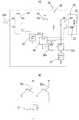
以下、図1から図6に基づいて、本発明の実施形態1に係る充電装置の説明を行なう。本実施形態に係る充電装置は、電動工具に使用されるバッテリの充電装置である。ここで、図1は実施形態1に係る充電装置の回路構成を表すブロック図等であり、図2は充電装置を構成する充電器、及び電池パックの斜視図である。図3は電池パックとパソコンとの関係を表す斜視図、図4は充電装置の動作を表すフローチャート、図5は発光手段を表す模式図である。また、図6は充電装置の回路構成の変更例を表すブロック図等である。(Embodiment 1)
Hereinafter, based on FIGS. 1-6, the charging device which concerns on Embodiment 1 of this invention is demonstrated. The charging device according to the present embodiment is a battery charging device used in an electric tool. Here, FIG. 1 is a block diagram showing a circuit configuration of the charging device according to the first embodiment, and FIG. 2 is a perspective view of a charger and a battery pack constituting the charging device. 3 is a perspective view showing the relationship between the battery pack and the personal computer, FIG. 4 is a flowchart showing the operation of the charging device, and FIG. 5 is a schematic view showing the light emitting means. FIG. 6 is a block diagram showing a modification example of the circuit configuration of the charging apparatus.
<充電装置10及び電池パック20について>
充電装置10は、図1(A)に示すように、電動工具(図示省略)のバッテリ22を収納する電池パック20と、前記バッテリ22の充電を行う充電器30とから構成されている。
電池パック20は角形をした密閉容器であり、図3に示すように、上面に連結部25が形成されている。そして、その連結部25の所定位置にバッテリ用のコネクタCN1が設けられている。コネクタCN1には、図1(A)に示すように、バッテリ22用の+、−端子と、後記するデータ記憶部27の端末である通信端子Tとが設けられている。
電池パック20の連結部25は、電動工具の電池パック接続部(図示省略)に連結される部分であり、その連結部25と電池パック接続部とが連結されることで、電動工具と電池パック20が一体化される。そして、この状態で、電池パック20のコネクタCN1(+、−端子)と前記電動工具の電気回路のコネクタ(図示省略)とが電気的に接続される。これにより、電動工具をバッテリ22の電力で駆動できるようになる。<About
As shown in FIG. 1A, the
The
The connecting
電池パック20内には、図1(A)に示すように、データ記憶部27が設けられている。データ記憶部27は複数種類の音パターンのデータ、例えば、メロディやブザー音のデータを記憶する部分であり、データの書き換えも可能なように構成されている。
さらに、電池パック20のコネクタCN1は、図3に示すように、例えば、USBコネクタ等を利用してパソコン40に接続されるデータ変換アダプタ43が接続可能になっている。データ変換アダプタ43は、パソコン40と電池パック20のデータ記憶部27とを接続するアダプタであり、パソコン40のデータを電池パック20のデータ記憶部27に伝送できるように構成されている。これにより、インターネットを利用してパソコン40でダウンロードしたメロディのデータを電池パック20のデータ記憶部27に書き込むことが可能になる。As shown in FIG. 1A, a
Further, as shown in FIG. 3, the connector CN1 of the
<充電器30について>
充電器30は、図2に示すように、箱形のハウジング30xを備えており、そのハウジング30xの上面右側に電池パック20との連結部35が形成されている。そして、その連結部35の所定位置に充電用コネクタCN2が設けられている。充電用コネクタCN2には、図1(A)に示すように、電池パック20のコネクタCN1と同様に、バッテリ用の+、−端子と、通信端子Tとが設けられている。
充電器30の連結部35は、電池パック20の連結部25が後方から連結されるように構成されている。即ち、充電器30の連結部35に対して電池パック20の連結部25が、図2に示すように、後方から前方にスライドさせられることにより、充電器30の連結部35と電池パック20の連結部25とが嵌合し、両者25,35が連結される。そして、充電器30の連結部35と電池パック20の連結部25とが連結されることで、電池パック20のバッテリ用のコネクタCN1と充電器30の充電用コネクタCN2とが電気的に接続される。<About
As shown in FIG. 2, the
The connecting
充電器30は、図1(A)に示すように、電源コード30rを備えており、その電源コード30rのプラグが家庭用のAC(交流)電源のコンセント(図示省略)に差し込み可能に構成されている。電源コード30rは充電器30の直流電源装置31の入力端子31a,31bに接続されている。
直流電源装置31は、交流の電源を二種類の直流電源、即ち、バッテリ充電用の第1直流電源(Vpボルト電源)と、制御電源用の第2直流電源(Vcボルト電源)とに変換するための装置である。
第1直流電源(Vpボルト電源)は、直流電源装置31の第1出力端子31p,Eから出力され、CPU34(後記する)で制御されるスイッチ36を介して充電用コネクタCN2の(+、−端子)に接続されている。なお、符号Eはアース端子を表している。このため、充電器30の充電用コネクタCN2と電池パック20のバッテリ用のコネクタCN1とが接続され、さらに前記スイッチ36がオンした状態で、直流電源装置31の第1直流電源と電池パック20のバッテリ22とが電気的に接続されて充電が行なわれる。As shown in FIG. 1A, the
The DC
The first DC power supply (Vp volt power supply) is output from the
直流電源装置31の第2直流電源(Vcボルト電源)は、第2出力端子31c,Eを介して制御用電源装置33に接続されている。制御電源装置33は、CPU34、及び音声発生素子37等の定電圧電源として使用される。
CPU34は、図示されていないメモリに格納されているプログラムに基づいてバッテリ22の充電制御を行なう部分である。このため、CPU34は、バッテリ22の電圧や温度等によりそのバッテリ22の充電状態を監視できるように構成されている。そして、充電完了と判定したときに前記スイッチ36をオフにしてバッテリ22の充電を停止する。
CPU34は、充電器30の充電用コネクタCN2と電池パック20のバッテリ用のコネクタCN1とが接続された状態で、通信端子Tを介して電池パック20のデータ記憶部27に接続される。CPU34のメモリには、電池パック20のデータ記憶部27に保存されているメロディ等のデータとCPU34内に予め記憶されているメロディ等のデータを選択するプログラムが格納されている。そして、選択したメロディ等のデータに基づいて、CPU34は、バッテリ22の充電完了時に第1駆動部38aを動作させ、音声発生素子37からメロディ等の音声を発生させる。The second DC power supply (Vc volt power supply) of the DC
The
The
音声発生素子37は、例えば、圧電ブザーや圧電スピーカ等であり、図1(A)(B)に示すように、第1駆動部38a、あるいは第2駆動部38bによって動作させられる。第1駆動部38a、第2駆動部38bは、トランジスタ等のスイッチング素子であり、CPU34からの信号Sで動作する。第1駆動部38aの電源端子は、図1(B)に示すように、充電用コネクタCN2の(+端子)に接続されており、バッテリ22の電圧Vpが加わるようになっている。第2駆動部38bの電源端子は、制御用電源装置33に接続されており、電圧Vcが加わるようになっている。ここで、Vc<Vpに設定されているため、第1駆動部38aが動作した状態では音声発生素子37に高電圧(Vp)が印加され、音声発生素子37の発生音は大きくなる。また、第2駆動部38bが動作した状態では音声発生素子37に低電圧(Vc)が印加され、音声発生素子37の発生音は小さくなる。
また、図5に示すように、CPU34が取付けられる電気回路基板には、LED30eが装着されており、そのLED30eが充電完了時にCPU34の信号で動作させられる。なお、LED30eを覆う充電器30のハウジング30xは予め決められた範囲が透明に形成されている。このため、充電完了時にLED30eが発光すると、その光が充電器30のケース30xの外に照射される。The
As shown in FIG. 5, an
<本実施形態に係る充電装置10の動作について>
次に、図4に示すフローチャートに基づいて本実施形態に係る充電装置10の動作について説明する。ここで、図4のフローチャートに基づく処理は、CPU34のメモリに格納されているプログラムに従って実行される。
先ず、充電器30の連結部35に対して電池パック20の連結部25が連結されていない状態、即ち、充電器30の充電用コネクタCN2と電池パック20のコネクタCN1とが接続されていない状態では、スイッチ36は、図1(A)に示すように、CPU34によってオフ状態に保持されている(バッテリ挿入待(ステップS101))。ここで、バッテリ挿入待であるか否の判定は、例えば、CPU34で充電用コネクタCN2の(+端子)の電圧を監視することにより行なう。即ち、充電用コネクタCN2の(+端子)の電圧が零であれば、充電用コネクタCN2の(+端子)がバッテリ22に接続されておらず、バッテリ挿入待と判定される。なお、充電用コネクタCN2の(+端子)の電圧を監視する代わりに、CPU34と電池パック20のデータ記憶部27とが接続されていないことを検知して、バッテリ挿入待と判定することも可能である。<Operation of
Next, the operation of the charging
First, a state in which the connecting
充電器30の連結部35に対して電池パック20の連結部25が連結されて、充電器30の充電用コネクタCN2と電池パック20のコネクタCN1とが接続されると、例えば、CPU34が充電用コネクタCN2の(+端子)を介してバッテリ22の電圧が検知される。これにより、バッテリ挿入と判定される(ステップS102)。そして、電池パック20のコネクタCN1と充電用コネクタCN2とが接続されると(バッテリ挿入)、CPU34が電池パック20のデータ記憶部27に対してメロディのデータを要求する(ステップS103)。電池パック20のデータ記憶部27にメロディのデータが記憶されている場合には(ステップS104 YES)、それらのメロディのデータがCPU34に格納される(ステップS105)。次に、メロディのデータ、あるいはメロディ以外音(ブザー音)のデータにおける最初の曲番号がCPU34内のデータ記憶部からCPU34の作業エリアにコピーされる(ステップS106)。
そして、作業エリアにコピーされた最初の曲番号がブザー音に対応する場合には(ステップS107 YES)、CPU34が第2駆動部38bに対してブザー音信号を出力する。これにより、音声発生素子37は、「ピー」という音を発生させる(ステップS108)。なお、音声発生素子37には、第2駆動部38bにより制御用の電圧Vcが加えられるため、音声発生素子37の発生音は小さくなる。
また、作業エリアにコピーされた最初の曲番号がブザー音でない場合、即ち、メロディ音である場合には(ステップS107 NO)、CPU34が第2駆動部38bに対してその曲番号に対応するメロディ信号を出力する。これにより、音声発生素子37はメロディ信号に対応するメロディ音を発生させる(ステップS109)。When the connecting
If the first music number copied to the work area corresponds to a buzzer sound (YES in step S107), the
If the first song number copied to the work area is not a buzzer sound, that is, if it is a melody sound (NO in step S107), the
このとき、ブザー音、あるいはメロディ音を別のメロディ音に変更したい場合には、音声発生素子37がブザー音、あるいはメロディ音を発生させてから3秒以内に、充電器30の充電用コネクタCN2と電池パック20のコネクタCN1との接続を解除する。これにより、ステップS110の判定(バッテリ有り?)はNOとなる。さらに、充電器30の充電用コネクタCN2と電池パック20のコネクタCN1との接続が解除されてから3秒以内(ステップS120 NO)に再び両コネクタCN1,CN2を接続させる(ステップS123 YES)。これにより、CPU34内のデータ記憶部に記憶されている次の曲番号が作業エリアにコピーされる。そして、処理は、ステップ107に戻り、ここで次の曲番号がブザー音か否か判定される。そして、その曲番号がブザー音に対応する場合には(ステップS107 YES)、音声発生素子37は「ピー」という音を発生させる(ステップS108)。また、その曲番号がブザー音でない場合には(ステップS107 NO)、音声発生素子37はメロディ信号に対応するメロディ音を発生させる(ステップS109)。 At this time, when it is desired to change the buzzer sound or the melody sound to another melody sound, the charging connector CN2 of the
さらに、メロディ音を変更したい場合には、上記したステップS110、ステップS120、ステップS123、ステップ124、及びステップS107〜110の処理を繰り返り実行する。
ここで、充電器30の充電用コネクタCN2と電池パック20のコネクタCN1との接続解除を3秒以上継続すると(ステップS120 YES)、バッテリの抜けが確定し(ステップS121)、処理はステップS101のバッテリ挿入待状態に戻される。
前記メロディを変更する必要がない場合には、ステップS109で鳴らされたメロディ音をそのまま鳴らし続ける。そして、メロディ音が鳴ってから3秒が経過すると(ステップS111 YES)、そのメロディ音の曲番号が最初の曲番号に書き換えられて(ステップS112)、メロディ音が停止する。この段階で、メロディ等の選択が終了する。
即ち、CPU34、及びステップS110、ステップS120、ステップS123、ステップ124、及びステップS107〜110の処理が本発明の音パターン選択手段に相当し、充電器30のCPU34内のデータ記憶部が本発明の音パターン記憶手段に相当する。Furthermore, when it is desired to change the melody sound, the above-described processes of Step S110, Step S120, Step S123,
Here, when the connection between the charging connector CN2 of the
If it is not necessary to change the melody, the melody sound generated in step S109 is continuously played. Then, when 3 seconds elapse after the melody sound is sounded (YES in step S111), the music number of the melody sound is rewritten to the first music number (step S112), and the melody sound is stopped. At this stage, selection of melody and the like is completed.
That is, the
このようにして、メロディ等の選択が終了すると、CPU34の信号でスイッチ36がオンし、直流電源装置31の第1直流電源の電圧が電池パック20のバッテリ22に印加されるようになる。即ち、バッテリ22の充電が開始される(ステップS113)。そして、時間が経過し、バッテリ22の充電が完了すると、前記スイッチ36がオフする(ステップS114)。さらに、CPU34が第1駆動部38aに対して選択したメロディの信号を出力する。これにより、音声発生素子37は、選択したメロディ音を発生させる(ステップS115)。ここで、音声発生素子37には、第1駆動部38aによってバッテリ22の電圧Vpが加えられるため、前記音声発生素子37の発生音は大きくなる。また、CPU34は、メロディ等の発生と同時にLED30eを発光させる。
即ち、直流電源装置31の第1直流電源、CPU34、及びスイッチ36が本発明の充電手段に相当し、第1駆動部38a、音声発生素子37が本発明の発音手段に相当する。また、CPU34、及びLED30eが本発明の発光手段に相当する。When the selection of the melody or the like is completed in this way, the
That is, the first DC power supply of the DC
<本発明に係る充電装置10の長所について>
本発明に係る充電装置10によると、CPU34の音パターン選択機能によって複数種類の音パターン、例えば、ブザー音やメロディ等のデータ中から所定のメロディ等のデータを選択することができる。このため、現場で同種類、あるいは類似する種類の充電装置が複数台使用されているときでも、他の充電装置の充電完了音と異なるメロディ等を選択することが可能になる。したがって、バッテリ22の充電完了時に、音声発生素子37により他の充電装置の充電完了音と異なるメロディ音を発生させることにより、使用者は特定の充電装置10におけるバッテリ22の充電完了を正確に知ることができる。
また、バッテリ22の充電が開始される前に、充電用コネクタCN2に対するバッテリ側のコネクタCN1の接続解除、及び再接続を繰り返すことで、電池パック20のデータ記憶部27に記憶されているメロディ等のデータ、及びCPU34内に予め記憶されているメロディ等のデータを順番に選択することが可能になる。したがって、メロディ等の切替えスイッチ等を設ける必要がなくなり、コスト低減を図ることができる。<Advantages of
According to the charging
In addition, by repeatedly disconnecting and reconnecting the battery-side connector CN1 with respect to the charging connector CN2 before charging the
また、音声発生素子37はメロディ等のデータが選択される際、選択されたメロディ等のデータに基づく音を充電完了時よりも小さい音で発生させる。
このため、音を聞きながらメロディ等を選択できるようになり、正確にメロディ等の選択が行なえる。
また、電池パック20のデータ記憶部27は、パソコン40によってメロディのデータを書き込み可能なように構成されている。このため、例えば、パソコン40によりインターネットを利用して曲をダウンロードすることにより、使用者の好みに応じたメロディを得ることができ、他の充電装置と明確に区別できるようになる。
また、バッテリ22の充電が完了したときに、発光素子(LED)30eを発光させる発光手段を備えているため、バッテリ22の充電完了がさらに認識し易くなる。Further, when data such as a melody is selected, the
Therefore, it becomes possible to select a melody or the like while listening to the sound, and the melody or the like can be selected accurately.
The
Moreover, since the light emitting means for emitting the light emitting element (LED) 30e when the charging of the
<変更例>
ここで、本発明は上記実施形態に限定されるものではなく、本発明の要旨を逸脱しない範囲における変更が可能である。例えば、本実施形態では、図1(A)に示すように、第1駆動部38aと第2駆動部38bとを使用して、メロディの選択時と充電完了時とで音声発生素子37に印加される電圧を変化させる例を示した。しかし、図6(A)(B)に示す構成により、メロディの選択時と充電完了時とで、音声発生素子37に印加される電圧を変化させることも可能である。即ち、上記構成では、図6(B)に示すように、バッテリ22(Vp)に接続される第1整流部39aと、制御用電源Vcよりも高い電圧(Vh)の直流電源に接続される第2整流部39bとを備えており、第1整流部39a、及び第2整流部39bの出力側が音声発生素子37に接続されている。さらに、音声発生素子37とアースEとの間には駆動部38が直列に接続されている。これにより、電圧Vpと電圧Vhとの高い方の電圧が加わるようにし、メロディの選択時、及び充電完了時の発生音を極力大きくすることが可能になる。
また、本実施形態では、充電完了時にメロディ音を発生させ、同時にLED30eを発光させる例を示したが、例えば、携帯電話で受信可能な充電完了信号を発信する発信手段を備えることも可能である。これにより、現場から遠く離れた場所でも、充電完了を知ることができる。
また、本実施形態では、充電用コネクタCN2に対するバッテリ側のコネクタCN1の接続解除、及び再接続を繰り返すことで、メロディ等の選択を行なう例を示したが、スイッチ等によりメロディ等の選択を行なうことも可能である。<Example of change>
Here, the present invention is not limited to the above-described embodiment, and can be modified without departing from the gist of the present invention. For example, in the present embodiment, as shown in FIG. 1A, the
Further, in the present embodiment, an example in which a melody sound is generated at the time of completion of charging and the
In the present embodiment, an example is shown in which a melody or the like is selected by repeatedly disconnecting and reconnecting the battery-side connector CN1 with respect to the charging connector CN2, but a melody or the like is selected by a switch or the like. It is also possible.
20 電池パック
22 バッテリ
27 データ記憶部(音パターン記憶手段)
CN1 バッテリ側のコネクタ
CN2 充電コネクタ
30 充電器
30e LED(発光手段)
31 直流電源装置(充電手段)
34 CPU(充電手段、音パターン選択手段)
36 スイッチ(充電手段)
37 音声発生素子(発音手段)
38a 第1駆動部(発音手段)
38b 第2駆動部(発音手段)
40 パソコン
43 データ変換アダプタ
20
CN1 Battery side connector
31 DC power supply (charging means)
34 CPU (charging means, sound pattern selection means)
36 switch (charging means)
37 Sound generator (sounding means)
38a 1st drive part (sounding means)
38b Second drive unit (sounding means)
40
Claims (6)
Translated fromJapanese前記バッテリ側のコネクタが前記充電用コネクタに接続されている状態で前記バッテリの充電を行なう充電手段と、
複数種類の音パターンのデータを記憶できる音パターン記憶手段と、
前記音パターン記憶手段に記憶されている複数種類の音パターンのデータから所定の音パターンのデータを選択する音パターン選択手段と、
前記充電手段による前記バッテリの充電が完了したときに、前記音パターン選択手段により選択された所定の音パターンのデータに基づいて音を発生させる発音手段とを有する充電装置であって、
前記充電手段は、バッテリ側のコネクタが充電用コネクタに所定時間以上接続されている状態で前記バッテリの充電を開始する構成であり、
音パターン選択手段は、前記バッテリの充電が開始される前に、前記充電用コネクタに対する前記バッテリ側のコネクタの接続が解除され、さらに再接続が行なわれたときに、既に選択された音パターンのデータを音パターン記憶手段に記憶されている次の音パターンのデータに切替えることを特徴とする充電装置。A charging connector configured to be electrically connectable to a battery-side connector;
Charging means for charging the battery in a state in which the battery-side connector is connected to the charging connector;
Sound pattern storage means capable of storing data of multiple types of sound patterns;
Sound pattern selection means for selecting data of a predetermined sound pattern from data of a plurality of types of sound patterns stored in the sound pattern storage means;
A charging device comprising: a sound generation unit that generates a sound based on data of a predetermined sound pattern selected by the sound pattern selection unit when charging of the battery by the charging unit is completed;
The charging means is configured to start charging the battery in a state where the battery-side connector is connected to the charging connector for a predetermined time or more,
The sound pattern selection means is configured to cancel the connection of the battery-side connector to the charging connector before charging of the battery, and when the reconnection is performed, A charging apparatus characterizedby switching data to data of a next sound pattern stored in a sound pattern storage means .
発音手段は、音パターン選択手段が音パターンのデータを選択する際に、選択された音パターンのデータに基づく音を充電完了時よりも小さい音で発生させることを特徴とすることを特徴とする充電装置。The charging device according to claim 1,
The sound generation means is characterized in that, when the sound pattern selection means selects sound pattern data, a sound based on the selected sound pattern data is generated with a smaller sound than when the charging is completed. Charging device.
発音手段は、音の発生素子に印加される電圧を変化させることで、音の大きさを変化させられるように構成されていることを特徴とする充電装置。A charging device according to claim 1 or 2, wherein
The charging device, wherein the sound generating means is configured to change the volume of the sound by changing a voltage applied to the sound generating element .
音パターン記憶手段は、パソコンによってメロディのデータを書き込み可能なように構成されていることを特徴とする充電装置。The charging device according to any one of claims 1 to 3,
The charging device is characterized in that thesound pattern storage means is configured so that melody data can be written by a personal computer .
充電手段によるバッテリの充電が完了したときに、発光素子を発光させる発光手段を備えていることを特徴とする充電装置。The charging device according to any one of claims 1 to 4,
A charging device comprising: a light emitting unit that causes a light emitting element to emit light when charging of the battery by the charging unit is completed .
充電手段によるバッテリの充電が完了したときに、通信端末器で受信可能な充電完了信号を発信する発信手段を備えていることを特徴とする充電装置。The charging device according to any one of claims 1 to 5,
A charging device comprising: a transmission means for transmitting a charge completion signal receivable by a communication terminal when charging of the battery by the charging means is completed .
Priority Applications (4)
| Application Number | Priority Date | Filing Date | Title |
|---|---|---|---|
| JP2006121964AJP4566943B2 (en) | 2006-04-26 | 2006-04-26 | Charger |
| CN2006101564098ACN101064439B (en) | 2006-04-26 | 2006-12-29 | Battery charging systems |
| US11/790,228US7944175B2 (en) | 2006-04-26 | 2007-04-24 | Battery charging systems |
| EP07008439AEP1850444B1 (en) | 2006-04-26 | 2007-04-25 | Battery charging systems |
Applications Claiming Priority (1)
| Application Number | Priority Date | Filing Date | Title |
|---|---|---|---|
| JP2006121964AJP4566943B2 (en) | 2006-04-26 | 2006-04-26 | Charger |
Publications (2)
| Publication Number | Publication Date |
|---|---|
| JP2007295741A JP2007295741A (en) | 2007-11-08 |
| JP4566943B2true JP4566943B2 (en) | 2010-10-20 |
Family
ID=38235147
Family Applications (1)
| Application Number | Title | Priority Date | Filing Date |
|---|---|---|---|
| JP2006121964AActiveJP4566943B2 (en) | 2006-04-26 | 2006-04-26 | Charger |
Country Status (4)
| Country | Link |
|---|---|
| US (1) | US7944175B2 (en) |
| EP (1) | EP1850444B1 (en) |
| JP (1) | JP4566943B2 (en) |
| CN (1) | CN101064439B (en) |
Families Citing this family (509)
| Publication number | Priority date | Publication date | Assignee | Title |
|---|---|---|---|---|
| US20070084897A1 (en) | 2003-05-20 | 2007-04-19 | Shelton Frederick E Iv | Articulating surgical stapling instrument incorporating a two-piece e-beam firing mechanism |
| US9060770B2 (en) | 2003-05-20 | 2015-06-23 | Ethicon Endo-Surgery, Inc. | Robotically-driven surgical instrument with E-beam driver |
| US11998198B2 (en) | 2004-07-28 | 2024-06-04 | Cilag Gmbh International | Surgical stapling instrument incorporating a two-piece E-beam firing mechanism |
| US8215531B2 (en) | 2004-07-28 | 2012-07-10 | Ethicon Endo-Surgery, Inc. | Surgical stapling instrument having a medical substance dispenser |
| US11890012B2 (en) | 2004-07-28 | 2024-02-06 | Cilag Gmbh International | Staple cartridge comprising cartridge body and attached support |
| US9072535B2 (en) | 2011-05-27 | 2015-07-07 | Ethicon Endo-Surgery, Inc. | Surgical stapling instruments with rotatable staple deployment arrangements |
| US9237891B2 (en) | 2005-08-31 | 2016-01-19 | Ethicon Endo-Surgery, Inc. | Robotically-controlled surgical stapling devices that produce formed staples having different lengths |
| US10159482B2 (en) | 2005-08-31 | 2018-12-25 | Ethicon Llc | Fastener cartridge assembly comprising a fixed anvil and different staple heights |
| US11246590B2 (en) | 2005-08-31 | 2022-02-15 | Cilag Gmbh International | Staple cartridge including staple drivers having different unfired heights |
| US8800838B2 (en) | 2005-08-31 | 2014-08-12 | Ethicon Endo-Surgery, Inc. | Robotically-controlled cable-based surgical end effectors |
| US7934630B2 (en) | 2005-08-31 | 2011-05-03 | Ethicon Endo-Surgery, Inc. | Staple cartridges for forming staples having differing formed staple heights |
| US7673781B2 (en) | 2005-08-31 | 2010-03-09 | Ethicon Endo-Surgery, Inc. | Surgical stapling device with staple driver that supports multiple wire diameter staples |
| US7669746B2 (en) | 2005-08-31 | 2010-03-02 | Ethicon Endo-Surgery, Inc. | Staple cartridges for forming staples having differing formed staple heights |
| US11484312B2 (en) | 2005-08-31 | 2022-11-01 | Cilag Gmbh International | Staple cartridge comprising a staple driver arrangement |
| US20070106317A1 (en) | 2005-11-09 | 2007-05-10 | Shelton Frederick E Iv | Hydraulically and electrically actuated articulation joints for surgical instruments |
| US20110295295A1 (en) | 2006-01-31 | 2011-12-01 | Ethicon Endo-Surgery, Inc. | Robotically-controlled surgical instrument having recording capabilities |
| US11793518B2 (en) | 2006-01-31 | 2023-10-24 | Cilag Gmbh International | Powered surgical instruments with firing system lockout arrangements |
| US8161977B2 (en) | 2006-01-31 | 2012-04-24 | Ethicon Endo-Surgery, Inc. | Accessing data stored in a memory of a surgical instrument |
| US8708213B2 (en) | 2006-01-31 | 2014-04-29 | Ethicon Endo-Surgery, Inc. | Surgical instrument having a feedback system |
| US8186555B2 (en) | 2006-01-31 | 2012-05-29 | Ethicon Endo-Surgery, Inc. | Motor-driven surgical cutting and fastening instrument with mechanical closure system |
| US7753904B2 (en) | 2006-01-31 | 2010-07-13 | Ethicon Endo-Surgery, Inc. | Endoscopic surgical instrument with a handle that can articulate with respect to the shaft |
| US20120292367A1 (en) | 2006-01-31 | 2012-11-22 | Ethicon Endo-Surgery, Inc. | Robotically-controlled end effector |
| US20110024477A1 (en) | 2009-02-06 | 2011-02-03 | Hall Steven G | Driven Surgical Stapler Improvements |
| US8820603B2 (en) | 2006-01-31 | 2014-09-02 | Ethicon Endo-Surgery, Inc. | Accessing data stored in a memory of a surgical instrument |
| US7845537B2 (en) | 2006-01-31 | 2010-12-07 | Ethicon Endo-Surgery, Inc. | Surgical instrument having recording capabilities |
| US11224427B2 (en) | 2006-01-31 | 2022-01-18 | Cilag Gmbh International | Surgical stapling system including a console and retraction assembly |
| US11278279B2 (en) | 2006-01-31 | 2022-03-22 | Cilag Gmbh International | Surgical instrument assembly |
| US8763879B2 (en) | 2006-01-31 | 2014-07-01 | Ethicon Endo-Surgery, Inc. | Accessing data stored in a memory of surgical instrument |
| US9861359B2 (en) | 2006-01-31 | 2018-01-09 | Ethicon Llc | Powered surgical instruments with firing system lockout arrangements |
| US8236010B2 (en) | 2006-03-23 | 2012-08-07 | Ethicon Endo-Surgery, Inc. | Surgical fastener and cutter with mimicking end effector |
| US8992422B2 (en) | 2006-03-23 | 2015-03-31 | Ethicon Endo-Surgery, Inc. | Robotically-controlled endoscopic accessory channel |
| US8322455B2 (en) | 2006-06-27 | 2012-12-04 | Ethicon Endo-Surgery, Inc. | Manually driven surgical cutting and fastening instrument |
| US10568652B2 (en) | 2006-09-29 | 2020-02-25 | Ethicon Llc | Surgical staples having attached drivers of different heights and stapling instruments for deploying the same |
| US7506791B2 (en) | 2006-09-29 | 2009-03-24 | Ethicon Endo-Surgery, Inc. | Surgical stapling instrument with mechanical mechanism for limiting maximum tissue compression |
| US10130359B2 (en) | 2006-09-29 | 2018-11-20 | Ethicon Llc | Method for forming a staple |
| US11980366B2 (en) | 2006-10-03 | 2024-05-14 | Cilag Gmbh International | Surgical instrument |
| US11291441B2 (en) | 2007-01-10 | 2022-04-05 | Cilag Gmbh International | Surgical instrument with wireless communication between control unit and remote sensor |
| US8684253B2 (en) | 2007-01-10 | 2014-04-01 | Ethicon Endo-Surgery, Inc. | Surgical instrument with wireless communication between a control unit of a robotic system and remote sensor |
| US8632535B2 (en) | 2007-01-10 | 2014-01-21 | Ethicon Endo-Surgery, Inc. | Interlock and surgical instrument including same |
| US8652120B2 (en) | 2007-01-10 | 2014-02-18 | Ethicon Endo-Surgery, Inc. | Surgical instrument with wireless communication between control unit and sensor transponders |
| US8459520B2 (en) | 2007-01-10 | 2013-06-11 | Ethicon Endo-Surgery, Inc. | Surgical instrument with wireless communication between control unit and remote sensor |
| US20080169333A1 (en) | 2007-01-11 | 2008-07-17 | Shelton Frederick E | Surgical stapler end effector with tapered distal end |
| US11039836B2 (en) | 2007-01-11 | 2021-06-22 | Cilag Gmbh International | Staple cartridge for use with a surgical stapling instrument |
| US7673782B2 (en) | 2007-03-15 | 2010-03-09 | Ethicon Endo-Surgery, Inc. | Surgical stapling instrument having a releasable buttress material |
| US8893946B2 (en) | 2007-03-28 | 2014-11-25 | Ethicon Endo-Surgery, Inc. | Laparoscopic tissue thickness and clamp load measuring devices |
| US8534528B2 (en) | 2007-06-04 | 2013-09-17 | Ethicon Endo-Surgery, Inc. | Surgical instrument having a multiple rate directional switching mechanism |
| US8931682B2 (en) | 2007-06-04 | 2015-01-13 | Ethicon Endo-Surgery, Inc. | Robotically-controlled shaft based rotary drive systems for surgical instruments |
| US11564682B2 (en) | 2007-06-04 | 2023-01-31 | Cilag Gmbh International | Surgical stapler device |
| US8408439B2 (en) | 2007-06-22 | 2013-04-02 | Ethicon Endo-Surgery, Inc. | Surgical stapling instrument with an articulatable end effector |
| US7753245B2 (en) | 2007-06-22 | 2010-07-13 | Ethicon Endo-Surgery, Inc. | Surgical stapling instruments |
| US11849941B2 (en) | 2007-06-29 | 2023-12-26 | Cilag Gmbh International | Staple cartridge having staple cavities extending at a transverse angle relative to a longitudinal cartridge axis |
| KR101474421B1 (en)* | 2007-11-23 | 2014-12-19 | 엘지전자 주식회사 | Mobile terminal having charging menu setting function and mutual charging method using the same |
| US8561870B2 (en) | 2008-02-13 | 2013-10-22 | Ethicon Endo-Surgery, Inc. | Surgical stapling instrument |
| US7819298B2 (en) | 2008-02-14 | 2010-10-26 | Ethicon Endo-Surgery, Inc. | Surgical stapling apparatus with control features operable with one hand |
| US8573465B2 (en) | 2008-02-14 | 2013-11-05 | Ethicon Endo-Surgery, Inc. | Robotically-controlled surgical end effector system with rotary actuated closure systems |
| US8752749B2 (en) | 2008-02-14 | 2014-06-17 | Ethicon Endo-Surgery, Inc. | Robotically-controlled disposable motor-driven loading unit |
| US8657174B2 (en) | 2008-02-14 | 2014-02-25 | Ethicon Endo-Surgery, Inc. | Motorized surgical cutting and fastening instrument having handle based power source |
| US8584919B2 (en) | 2008-02-14 | 2013-11-19 | Ethicon Endo-Sugery, Inc. | Surgical stapling apparatus with load-sensitive firing mechanism |
| US7866527B2 (en) | 2008-02-14 | 2011-01-11 | Ethicon Endo-Surgery, Inc. | Surgical stapling apparatus with interlockable firing system |
| US9179912B2 (en) | 2008-02-14 | 2015-11-10 | Ethicon Endo-Surgery, Inc. | Robotically-controlled motorized surgical cutting and fastening instrument |
| US7793812B2 (en) | 2008-02-14 | 2010-09-14 | Ethicon Endo-Surgery, Inc. | Disposable motor-driven loading unit for use with a surgical cutting and stapling apparatus |
| US8636736B2 (en) | 2008-02-14 | 2014-01-28 | Ethicon Endo-Surgery, Inc. | Motorized surgical cutting and fastening instrument |
| US8459525B2 (en) | 2008-02-14 | 2013-06-11 | Ethicon Endo-Sugery, Inc. | Motorized surgical cutting and fastening instrument having a magnetic drive train torque limiting device |
| US11986183B2 (en) | 2008-02-14 | 2024-05-21 | Cilag Gmbh International | Surgical cutting and fastening instrument comprising a plurality of sensors to measure an electrical parameter |
| JP5410110B2 (en) | 2008-02-14 | 2014-02-05 | エシコン・エンド−サージェリィ・インコーポレイテッド | Surgical cutting / fixing instrument with RF electrode |
| US8622274B2 (en) | 2008-02-14 | 2014-01-07 | Ethicon Endo-Surgery, Inc. | Motorized cutting and fastening instrument having control circuit for optimizing battery usage |
| US8758391B2 (en) | 2008-02-14 | 2014-06-24 | Ethicon Endo-Surgery, Inc. | Interchangeable tools for surgical instruments |
| US11272927B2 (en) | 2008-02-15 | 2022-03-15 | Cilag Gmbh International | Layer arrangements for surgical staple cartridges |
| US9585657B2 (en) | 2008-02-15 | 2017-03-07 | Ethicon Endo-Surgery, Llc | Actuator for releasing a layer of material from a surgical end effector |
| PL3476312T3 (en) | 2008-09-19 | 2024-03-11 | Ethicon Llc | Surgical stapler with apparatus for adjusting staple height |
| US7954686B2 (en) | 2008-09-19 | 2011-06-07 | Ethicon Endo-Surgery, Inc. | Surgical stapler with apparatus for adjusting staple height |
| US9386983B2 (en) | 2008-09-23 | 2016-07-12 | Ethicon Endo-Surgery, Llc | Robotically-controlled motorized surgical instrument |
| US8210411B2 (en) | 2008-09-23 | 2012-07-03 | Ethicon Endo-Surgery, Inc. | Motor-driven surgical cutting instrument |
| US11648005B2 (en) | 2008-09-23 | 2023-05-16 | Cilag Gmbh International | Robotically-controlled motorized surgical instrument with an end effector |
| US9005230B2 (en) | 2008-09-23 | 2015-04-14 | Ethicon Endo-Surgery, Inc. | Motorized surgical instrument |
| US9050083B2 (en) | 2008-09-23 | 2015-06-09 | Ethicon Endo-Surgery, Inc. | Motorized surgical instrument |
| US8608045B2 (en) | 2008-10-10 | 2013-12-17 | Ethicon Endo-Sugery, Inc. | Powered surgical cutting and stapling apparatus with manually retractable firing system |
| US8517239B2 (en) | 2009-02-05 | 2013-08-27 | Ethicon Endo-Surgery, Inc. | Surgical stapling instrument comprising a magnetic element driver |
| RU2525225C2 (en) | 2009-02-06 | 2014-08-10 | Этикон Эндо-Серджери, Инк. | Improvement of drive surgical suturing instrument |
| US8453907B2 (en) | 2009-02-06 | 2013-06-04 | Ethicon Endo-Surgery, Inc. | Motor driven surgical fastener device with cutting member reversing mechanism |
| US8444036B2 (en) | 2009-02-06 | 2013-05-21 | Ethicon Endo-Surgery, Inc. | Motor driven surgical fastener device with mechanisms for adjusting a tissue gap within the end effector |
| JP5432652B2 (en)* | 2009-09-25 | 2014-03-05 | パナソニック株式会社 | Battery charger for electric tools |
| US8220688B2 (en) | 2009-12-24 | 2012-07-17 | Ethicon Endo-Surgery, Inc. | Motor-driven surgical cutting instrument with electric actuator directional control assembly |
| US8851354B2 (en) | 2009-12-24 | 2014-10-07 | Ethicon Endo-Surgery, Inc. | Surgical cutting instrument that analyzes tissue thickness |
| JP5432761B2 (en) | 2010-02-12 | 2014-03-05 | 株式会社マキタ | Electric tool powered by multiple battery packs |
| JP5461221B2 (en) | 2010-02-12 | 2014-04-02 | 株式会社マキタ | Electric tool powered by multiple battery packs |
| US8783543B2 (en) | 2010-07-30 | 2014-07-22 | Ethicon Endo-Surgery, Inc. | Tissue acquisition arrangements and methods for surgical stapling devices |
| US20120078244A1 (en) | 2010-09-24 | 2012-03-29 | Worrell Barry C | Control features for articulating surgical device |
| US11925354B2 (en) | 2010-09-30 | 2024-03-12 | Cilag Gmbh International | Staple cartridge comprising staples positioned within a compressible portion thereof |
| US9351730B2 (en) | 2011-04-29 | 2016-05-31 | Ethicon Endo-Surgery, Llc | Tissue thickness compensator comprising channels |
| US12213666B2 (en) | 2010-09-30 | 2025-02-04 | Cilag Gmbh International | Tissue thickness compensator comprising layers |
| US9277919B2 (en) | 2010-09-30 | 2016-03-08 | Ethicon Endo-Surgery, Llc | Tissue thickness compensator comprising fibers to produce a resilient load |
| US9220501B2 (en) | 2010-09-30 | 2015-12-29 | Ethicon Endo-Surgery, Inc. | Tissue thickness compensators |
| US9332974B2 (en) | 2010-09-30 | 2016-05-10 | Ethicon Endo-Surgery, Llc | Layered tissue thickness compensator |
| US9386988B2 (en) | 2010-09-30 | 2016-07-12 | Ethicon End-Surgery, LLC | Retainer assembly including a tissue thickness compensator |
| US9055941B2 (en) | 2011-09-23 | 2015-06-16 | Ethicon Endo-Surgery, Inc. | Staple cartridge including collapsible deck |
| US9788834B2 (en) | 2010-09-30 | 2017-10-17 | Ethicon Llc | Layer comprising deployable attachment members |
| US8893949B2 (en) | 2010-09-30 | 2014-11-25 | Ethicon Endo-Surgery, Inc. | Surgical stapler with floating anvil |
| US9307989B2 (en) | 2012-03-28 | 2016-04-12 | Ethicon Endo-Surgery, Llc | Tissue stapler having a thickness compensator incorportating a hydrophobic agent |
| US11812965B2 (en) | 2010-09-30 | 2023-11-14 | Cilag Gmbh International | Layer of material for a surgical end effector |
| US9301753B2 (en) | 2010-09-30 | 2016-04-05 | Ethicon Endo-Surgery, Llc | Expandable tissue thickness compensator |
| US11298125B2 (en) | 2010-09-30 | 2022-04-12 | Cilag Gmbh International | Tissue stapler having a thickness compensator |
| US9364233B2 (en) | 2010-09-30 | 2016-06-14 | Ethicon Endo-Surgery, Llc | Tissue thickness compensators for circular surgical staplers |
| US9629814B2 (en) | 2010-09-30 | 2017-04-25 | Ethicon Endo-Surgery, Llc | Tissue thickness compensator configured to redistribute compressive forces |
| US9301752B2 (en) | 2010-09-30 | 2016-04-05 | Ethicon Endo-Surgery, Llc | Tissue thickness compensator comprising a plurality of capsules |
| US10945731B2 (en) | 2010-09-30 | 2021-03-16 | Ethicon Llc | Tissue thickness compensator comprising controlled release and expansion |
| US9314246B2 (en) | 2010-09-30 | 2016-04-19 | Ethicon Endo-Surgery, Llc | Tissue stapler having a thickness compensator incorporating an anti-inflammatory agent |
| RU2013119928A (en) | 2010-09-30 | 2014-11-10 | Этикон Эндо-Серджери, Инк. | A STAPLING SYSTEM CONTAINING A RETAINING MATRIX AND A LEVELING MATRIX |
| US9016542B2 (en) | 2010-09-30 | 2015-04-28 | Ethicon Endo-Surgery, Inc. | Staple cartridge comprising compressible distortion resistant components |
| US9232941B2 (en) | 2010-09-30 | 2016-01-12 | Ethicon Endo-Surgery, Inc. | Tissue thickness compensator comprising a reservoir |
| US8695866B2 (en) | 2010-10-01 | 2014-04-15 | Ethicon Endo-Surgery, Inc. | Surgical instrument having a power control circuit |
| AU2012250197B2 (en) | 2011-04-29 | 2017-08-10 | Ethicon Endo-Surgery, Inc. | Staple cartridge comprising staples positioned within a compressible portion thereof |
| US11207064B2 (en) | 2011-05-27 | 2021-12-28 | Cilag Gmbh International | Automated end effector component reloading system for use with a robotic system |
| US8692509B2 (en)* | 2011-06-23 | 2014-04-08 | Black & Decker Inc. | Charge control scheme for use in power tools |
| JPWO2013001909A1 (en)* | 2011-06-30 | 2015-02-23 | パナソニック株式会社 | Power supply |
| EP2735078B1 (en) | 2011-07-24 | 2017-10-04 | Makita Corporation | Power tool system and adapter therefor |
| US9050084B2 (en) | 2011-09-23 | 2015-06-09 | Ethicon Endo-Surgery, Inc. | Staple cartridge including collapsible deck arrangement |
| US9044230B2 (en) | 2012-02-13 | 2015-06-02 | Ethicon Endo-Surgery, Inc. | Surgical cutting and fastening instrument with apparatus for determining cartridge and firing motion status |
| JP6224070B2 (en) | 2012-03-28 | 2017-11-01 | エシコン・エンド−サージェリィ・インコーポレイテッドEthicon Endo−Surgery,Inc. | Retainer assembly including tissue thickness compensator |
| MX358135B (en) | 2012-03-28 | 2018-08-06 | Ethicon Endo Surgery Inc | Tissue thickness compensator comprising a plurality of layers. |
| US9198662B2 (en) | 2012-03-28 | 2015-12-01 | Ethicon Endo-Surgery, Inc. | Tissue thickness compensator having improved visibility |
| BR112014024098B1 (en) | 2012-03-28 | 2021-05-25 | Ethicon Endo-Surgery, Inc. | staple cartridge |
| US9101358B2 (en) | 2012-06-15 | 2015-08-11 | Ethicon Endo-Surgery, Inc. | Articulatable surgical instrument comprising a firing drive |
| US9119657B2 (en) | 2012-06-28 | 2015-09-01 | Ethicon Endo-Surgery, Inc. | Rotary actuatable closure arrangement for surgical end effector |
| BR112014032776B1 (en) | 2012-06-28 | 2021-09-08 | Ethicon Endo-Surgery, Inc | SURGICAL INSTRUMENT SYSTEM AND SURGICAL KIT FOR USE WITH A SURGICAL INSTRUMENT SYSTEM |
| US20140001231A1 (en) | 2012-06-28 | 2014-01-02 | Ethicon Endo-Surgery, Inc. | Firing system lockout arrangements for surgical instruments |
| US9072536B2 (en) | 2012-06-28 | 2015-07-07 | Ethicon Endo-Surgery, Inc. | Differential locking arrangements for rotary powered surgical instruments |
| US12383267B2 (en) | 2012-06-28 | 2025-08-12 | Cilag Gmbh International | Robotically powered surgical device with manually-actuatable reversing system |
| US11278284B2 (en) | 2012-06-28 | 2022-03-22 | Cilag Gmbh International | Rotary drive arrangements for surgical instruments |
| US9408606B2 (en) | 2012-06-28 | 2016-08-09 | Ethicon Endo-Surgery, Llc | Robotically powered surgical device with manually-actuatable reversing system |
| US20140005718A1 (en) | 2012-06-28 | 2014-01-02 | Ethicon Endo-Surgery, Inc. | Multi-functional powered surgical device with external dissection features |
| US9125662B2 (en) | 2012-06-28 | 2015-09-08 | Ethicon Endo-Surgery, Inc. | Multi-axis articulating and rotating surgical tools |
| US9028494B2 (en) | 2012-06-28 | 2015-05-12 | Ethicon Endo-Surgery, Inc. | Interchangeable end effector coupling arrangement |
| US9289256B2 (en) | 2012-06-28 | 2016-03-22 | Ethicon Endo-Surgery, Llc | Surgical end effectors having angled tissue-contacting surfaces |
| US9101385B2 (en) | 2012-06-28 | 2015-08-11 | Ethicon Endo-Surgery, Inc. | Electrode connections for rotary driven surgical tools |
| US9561038B2 (en) | 2012-06-28 | 2017-02-07 | Ethicon Endo-Surgery, Llc | Interchangeable clip applier |
| US8747238B2 (en) | 2012-06-28 | 2014-06-10 | Ethicon Endo-Surgery, Inc. | Rotary drive shaft assemblies for surgical instruments with articulatable end effectors |
| JP6290201B2 (en) | 2012-06-28 | 2018-03-07 | エシコン・エンド−サージェリィ・インコーポレイテッドEthicon Endo−Surgery,Inc. | Lockout for empty clip cartridge |
| US9282974B2 (en) | 2012-06-28 | 2016-03-15 | Ethicon Endo-Surgery, Llc | Empty clip cartridge lockout |
| US9386984B2 (en) | 2013-02-08 | 2016-07-12 | Ethicon Endo-Surgery, Llc | Staple cartridge comprising a releasable cover |
| US10092292B2 (en) | 2013-02-28 | 2018-10-09 | Ethicon Llc | Staple forming features for surgical stapling instrument |
| RU2672520C2 (en) | 2013-03-01 | 2018-11-15 | Этикон Эндо-Серджери, Инк. | Hingedly turnable surgical instruments with conducting ways for signal transfer |
| US9468438B2 (en) | 2013-03-01 | 2016-10-18 | Eticon Endo-Surgery, LLC | Sensor straightened end effector during removal through trocar |
| BR112015021082B1 (en) | 2013-03-01 | 2022-05-10 | Ethicon Endo-Surgery, Inc | surgical instrument |
| US9345481B2 (en) | 2013-03-13 | 2016-05-24 | Ethicon Endo-Surgery, Llc | Staple cartridge tissue thickness sensor system |
| US9808244B2 (en) | 2013-03-14 | 2017-11-07 | Ethicon Llc | Sensor arrangements for absolute positioning system for surgical instruments |
| US9629629B2 (en) | 2013-03-14 | 2017-04-25 | Ethicon Endo-Surgey, LLC | Control systems for surgical instruments |
| US9572577B2 (en) | 2013-03-27 | 2017-02-21 | Ethicon Endo-Surgery, Llc | Fastener cartridge comprising a tissue thickness compensator including openings therein |
| US9332984B2 (en) | 2013-03-27 | 2016-05-10 | Ethicon Endo-Surgery, Llc | Fastener cartridge assemblies |
| US9795384B2 (en) | 2013-03-27 | 2017-10-24 | Ethicon Llc | Fastener cartridge comprising a tissue thickness compensator and a gap setting element |
| BR112015026109B1 (en) | 2013-04-16 | 2022-02-22 | Ethicon Endo-Surgery, Inc | surgical instrument |
| US9826976B2 (en) | 2013-04-16 | 2017-11-28 | Ethicon Llc | Motor driven surgical instruments with lockable dual drive shafts |
| DE102013208834A1 (en) | 2013-05-14 | 2014-11-20 | Robert Bosch Gmbh | Data transmission with an electric machine |
| US9574644B2 (en) | 2013-05-30 | 2017-02-21 | Ethicon Endo-Surgery, Llc | Power module for use with a surgical instrument |
| MX369362B (en) | 2013-08-23 | 2019-11-06 | Ethicon Endo Surgery Llc | Firing member retraction devices for powered surgical instruments. |
| US9775609B2 (en) | 2013-08-23 | 2017-10-03 | Ethicon Llc | Tamper proof circuit for surgical instrument battery pack |
| US20150173749A1 (en) | 2013-12-23 | 2015-06-25 | Ethicon Endo-Surgery, Inc. | Surgical staples and staple cartridges |
| US9839428B2 (en) | 2013-12-23 | 2017-12-12 | Ethicon Llc | Surgical cutting and stapling instruments with independent jaw control features |
| US20150173756A1 (en) | 2013-12-23 | 2015-06-25 | Ethicon Endo-Surgery, Inc. | Surgical cutting and stapling methods |
| US9724092B2 (en) | 2013-12-23 | 2017-08-08 | Ethicon Llc | Modular surgical instruments |
| US9962161B2 (en) | 2014-02-12 | 2018-05-08 | Ethicon Llc | Deliverable surgical instrument |
| JP6462004B2 (en) | 2014-02-24 | 2019-01-30 | エシコン エルエルシー | Fastening system with launcher lockout |
| US20140166724A1 (en) | 2014-02-24 | 2014-06-19 | Ethicon Endo-Surgery, Inc. | Staple cartridge including a barbed staple |
| US10004497B2 (en) | 2014-03-26 | 2018-06-26 | Ethicon Llc | Interface systems for use with surgical instruments |
| US9913642B2 (en) | 2014-03-26 | 2018-03-13 | Ethicon Llc | Surgical instrument comprising a sensor system |
| US20150272580A1 (en) | 2014-03-26 | 2015-10-01 | Ethicon Endo-Surgery, Inc. | Verification of number of battery exchanges/procedure count |
| US10013049B2 (en) | 2014-03-26 | 2018-07-03 | Ethicon Llc | Power management through sleep options of segmented circuit and wake up control |
| BR112016021943B1 (en) | 2014-03-26 | 2022-06-14 | Ethicon Endo-Surgery, Llc | SURGICAL INSTRUMENT FOR USE BY AN OPERATOR IN A SURGICAL PROCEDURE |
| US12232723B2 (en) | 2014-03-26 | 2025-02-25 | Cilag Gmbh International | Systems and methods for controlling a segmented circuit |
| CN106456159B (en) | 2014-04-16 | 2019-03-08 | 伊西康内外科有限责任公司 | Fastener Cartridge Assembly and Nail Retainer Cover Arrangement |
| BR112016023825B1 (en) | 2014-04-16 | 2022-08-02 | Ethicon Endo-Surgery, Llc | STAPLE CARTRIDGE FOR USE WITH A SURGICAL STAPLER AND STAPLE CARTRIDGE FOR USE WITH A SURGICAL INSTRUMENT |
| US10327764B2 (en) | 2014-09-26 | 2019-06-25 | Ethicon Llc | Method for creating a flexible staple line |
| US20150297225A1 (en) | 2014-04-16 | 2015-10-22 | Ethicon Endo-Surgery, Inc. | Fastener cartridges including extensions having different configurations |
| CN106456176B (en) | 2014-04-16 | 2019-06-28 | 伊西康内外科有限责任公司 | Fastener Cartridge Including Extensions With Different Configurations |
| US10470768B2 (en) | 2014-04-16 | 2019-11-12 | Ethicon Llc | Fastener cartridge including a layer attached thereto |
| US10045781B2 (en) | 2014-06-13 | 2018-08-14 | Ethicon Llc | Closure lockout systems for surgical instruments |
| JP6300271B2 (en)* | 2014-07-22 | 2018-03-28 | 株式会社マキタ | Chainsaw |
| BR112017004361B1 (en) | 2014-09-05 | 2023-04-11 | Ethicon Llc | ELECTRONIC SYSTEM FOR A SURGICAL INSTRUMENT |
| US11311294B2 (en) | 2014-09-05 | 2022-04-26 | Cilag Gmbh International | Powered medical device including measurement of closure state of jaws |
| US10135242B2 (en) | 2014-09-05 | 2018-11-20 | Ethicon Llc | Smart cartridge wake up operation and data retention |
| US10105142B2 (en) | 2014-09-18 | 2018-10-23 | Ethicon Llc | Surgical stapler with plurality of cutting elements |
| CN107427300B (en) | 2014-09-26 | 2020-12-04 | 伊西康有限责任公司 | Surgical suture buttresses and auxiliary materials |
| US11523821B2 (en) | 2014-09-26 | 2022-12-13 | Cilag Gmbh International | Method for creating a flexible staple line |
| US10076325B2 (en) | 2014-10-13 | 2018-09-18 | Ethicon Llc | Surgical stapling apparatus comprising a tissue stop |
| US9924944B2 (en) | 2014-10-16 | 2018-03-27 | Ethicon Llc | Staple cartridge comprising an adjunct material |
| US10517594B2 (en) | 2014-10-29 | 2019-12-31 | Ethicon Llc | Cartridge assemblies for surgical staplers |
| US11141153B2 (en) | 2014-10-29 | 2021-10-12 | Cilag Gmbh International | Staple cartridges comprising driver arrangements |
| US9844376B2 (en) | 2014-11-06 | 2017-12-19 | Ethicon Llc | Staple cartridge comprising a releasable adjunct material |
| US10736636B2 (en) | 2014-12-10 | 2020-08-11 | Ethicon Llc | Articulatable surgical instrument system |
| MX389118B (en) | 2014-12-18 | 2025-03-20 | Ethicon Llc | SURGICAL INSTRUMENT WITH AN ANVIL THAT CAN BE SELECTIVELY MOVED ON A DISCRETE, NON-MOBILE AXIS RELATIVE TO A STAPLE CARTRIDGE. |
| US10188385B2 (en) | 2014-12-18 | 2019-01-29 | Ethicon Llc | Surgical instrument system comprising lockable systems |
| US9943309B2 (en) | 2014-12-18 | 2018-04-17 | Ethicon Llc | Surgical instruments with articulatable end effectors and movable firing beam support arrangements |
| US9844375B2 (en) | 2014-12-18 | 2017-12-19 | Ethicon Llc | Drive arrangements for articulatable surgical instruments |
| US10085748B2 (en) | 2014-12-18 | 2018-10-02 | Ethicon Llc | Locking arrangements for detachable shaft assemblies with articulatable surgical end effectors |
| US9987000B2 (en) | 2014-12-18 | 2018-06-05 | Ethicon Llc | Surgical instrument assembly comprising a flexible articulation system |
| US10117649B2 (en) | 2014-12-18 | 2018-11-06 | Ethicon Llc | Surgical instrument assembly comprising a lockable articulation system |
| US9844374B2 (en) | 2014-12-18 | 2017-12-19 | Ethicon Llc | Surgical instrument systems comprising an articulatable end effector and means for adjusting the firing stroke of a firing member |
| US10159483B2 (en) | 2015-02-27 | 2018-12-25 | Ethicon Llc | Surgical apparatus configured to track an end-of-life parameter |
| US9993258B2 (en) | 2015-02-27 | 2018-06-12 | Ethicon Llc | Adaptable surgical instrument handle |
| US10180463B2 (en) | 2015-02-27 | 2019-01-15 | Ethicon Llc | Surgical apparatus configured to assess whether a performance parameter of the surgical apparatus is within an acceptable performance band |
| US11154301B2 (en) | 2015-02-27 | 2021-10-26 | Cilag Gmbh International | Modular stapling assembly |
| US9895148B2 (en) | 2015-03-06 | 2018-02-20 | Ethicon Endo-Surgery, Llc | Monitoring speed control and precision incrementing of motor for powered surgical instruments |
| JP2020121162A (en) | 2015-03-06 | 2020-08-13 | エシコン エルエルシーEthicon LLC | Time dependent evaluation of sensor data to determine stability element, creep element and viscoelastic element of measurement |
| US9808246B2 (en) | 2015-03-06 | 2017-11-07 | Ethicon Endo-Surgery, Llc | Method of operating a powered surgical instrument |
| US10687806B2 (en) | 2015-03-06 | 2020-06-23 | Ethicon Llc | Adaptive tissue compression techniques to adjust closure rates for multiple tissue types |
| US10548504B2 (en) | 2015-03-06 | 2020-02-04 | Ethicon Llc | Overlaid multi sensor radio frequency (RF) electrode system to measure tissue compression |
| US9993248B2 (en) | 2015-03-06 | 2018-06-12 | Ethicon Endo-Surgery, Llc | Smart sensors with local signal processing |
| US10617412B2 (en) | 2015-03-06 | 2020-04-14 | Ethicon Llc | System for detecting the mis-insertion of a staple cartridge into a surgical stapler |
| US10441279B2 (en) | 2015-03-06 | 2019-10-15 | Ethicon Llc | Multiple level thresholds to modify operation of powered surgical instruments |
| US9901342B2 (en) | 2015-03-06 | 2018-02-27 | Ethicon Endo-Surgery, Llc | Signal and power communication system positioned on a rotatable shaft |
| US10045776B2 (en) | 2015-03-06 | 2018-08-14 | Ethicon Llc | Control techniques and sub-processor contained within modular shaft with select control processing from handle |
| US10245033B2 (en) | 2015-03-06 | 2019-04-02 | Ethicon Llc | Surgical instrument comprising a lockable battery housing |
| US9924961B2 (en) | 2015-03-06 | 2018-03-27 | Ethicon Endo-Surgery, Llc | Interactive feedback system for powered surgical instruments |
| US10433844B2 (en) | 2015-03-31 | 2019-10-08 | Ethicon Llc | Surgical instrument with selectively disengageable threaded drive systems |
| US10154841B2 (en) | 2015-06-18 | 2018-12-18 | Ethicon Llc | Surgical stapling instruments with lockout arrangements for preventing firing system actuation when a cartridge is spent or missing |
| US10835249B2 (en) | 2015-08-17 | 2020-11-17 | Ethicon Llc | Implantable layers for a surgical instrument |
| MX2022009705A (en) | 2015-08-26 | 2022-11-07 | Ethicon Llc | Surgical staples comprising hardness variations for improved fastening of tissue. |
| MX2018002392A (en) | 2015-08-26 | 2018-08-01 | Ethicon Llc | Staple cartridge assembly comprising various tissue compression gaps and staple forming gaps. |
| US10980538B2 (en) | 2015-08-26 | 2021-04-20 | Ethicon Llc | Surgical stapling configurations for curved and circular stapling instruments |
| RU2725081C2 (en) | 2015-08-26 | 2020-06-29 | ЭТИКОН ЭлЭлСи | Strips with surgical staples allowing the presence of staples with variable properties and providing simple loading of the cartridge |
| US10238390B2 (en) | 2015-09-02 | 2019-03-26 | Ethicon Llc | Surgical staple cartridges with driver arrangements for establishing herringbone staple patterns |
| MX2022006189A (en) | 2015-09-02 | 2022-06-16 | Ethicon Llc | Surgical staple configurations with camming surfaces located between portions supporting surgical staples. |
| US10327769B2 (en) | 2015-09-23 | 2019-06-25 | Ethicon Llc | Surgical stapler having motor control based on a drive system component |
| US10076326B2 (en) | 2015-09-23 | 2018-09-18 | Ethicon Llc | Surgical stapler having current mirror-based motor control |
| US10363036B2 (en) | 2015-09-23 | 2019-07-30 | Ethicon Llc | Surgical stapler having force-based motor control |
| US10238386B2 (en) | 2015-09-23 | 2019-03-26 | Ethicon Llc | Surgical stapler having motor control based on an electrical parameter related to a motor current |
| US10105139B2 (en) | 2015-09-23 | 2018-10-23 | Ethicon Llc | Surgical stapler having downstream current-based motor control |
| US10085751B2 (en) | 2015-09-23 | 2018-10-02 | Ethicon Llc | Surgical stapler having temperature-based motor control |
| US10299878B2 (en) | 2015-09-25 | 2019-05-28 | Ethicon Llc | Implantable adjunct systems for determining adjunct skew |
| US10433846B2 (en) | 2015-09-30 | 2019-10-08 | Ethicon Llc | Compressible adjunct with crossing spacer fibers |
| US10980539B2 (en) | 2015-09-30 | 2021-04-20 | Ethicon Llc | Implantable adjunct comprising bonded layers |
| US11890015B2 (en) | 2015-09-30 | 2024-02-06 | Cilag Gmbh International | Compressible adjunct with crossing spacer fibers |
| US10478188B2 (en) | 2015-09-30 | 2019-11-19 | Ethicon Llc | Implantable layer comprising a constricted configuration |
| US10368865B2 (en) | 2015-12-30 | 2019-08-06 | Ethicon Llc | Mechanisms for compensating for drivetrain failure in powered surgical instruments |
| US10265068B2 (en) | 2015-12-30 | 2019-04-23 | Ethicon Llc | Surgical instruments with separable motors and motor control circuits |
| US10292704B2 (en) | 2015-12-30 | 2019-05-21 | Ethicon Llc | Mechanisms for compensating for battery pack failure in powered surgical instruments |
| US10413291B2 (en) | 2016-02-09 | 2019-09-17 | Ethicon Llc | Surgical instrument articulation mechanism with slotted secondary constraint |
| BR112018016098B1 (en) | 2016-02-09 | 2023-02-23 | Ethicon Llc | SURGICAL INSTRUMENT |
| US11213293B2 (en) | 2016-02-09 | 2022-01-04 | Cilag Gmbh International | Articulatable surgical instruments with single articulation link arrangements |
| US10258331B2 (en) | 2016-02-12 | 2019-04-16 | Ethicon Llc | Mechanisms for compensating for drivetrain failure in powered surgical instruments |
| US11224426B2 (en) | 2016-02-12 | 2022-01-18 | Cilag Gmbh International | Mechanisms for compensating for drivetrain failure in powered surgical instruments |
| US10448948B2 (en) | 2016-02-12 | 2019-10-22 | Ethicon Llc | Mechanisms for compensating for drivetrain failure in powered surgical instruments |
| US10413297B2 (en) | 2016-04-01 | 2019-09-17 | Ethicon Llc | Surgical stapling system configured to apply annular rows of staples having different heights |
| US10617413B2 (en) | 2016-04-01 | 2020-04-14 | Ethicon Llc | Closure system arrangements for surgical cutting and stapling devices with separate and distinct firing shafts |
| US11607239B2 (en) | 2016-04-15 | 2023-03-21 | Cilag Gmbh International | Systems and methods for controlling a surgical stapling and cutting instrument |
| US10335145B2 (en) | 2016-04-15 | 2019-07-02 | Ethicon Llc | Modular surgical instrument with configurable operating mode |
| US10456137B2 (en) | 2016-04-15 | 2019-10-29 | Ethicon Llc | Staple formation detection mechanisms |
| US11179150B2 (en) | 2016-04-15 | 2021-11-23 | Cilag Gmbh International | Systems and methods for controlling a surgical stapling and cutting instrument |
| US10357247B2 (en) | 2016-04-15 | 2019-07-23 | Ethicon Llc | Surgical instrument with multiple program responses during a firing motion |
| US10405859B2 (en) | 2016-04-15 | 2019-09-10 | Ethicon Llc | Surgical instrument with adjustable stop/start control during a firing motion |
| US10492783B2 (en) | 2016-04-15 | 2019-12-03 | Ethicon, Llc | Surgical instrument with improved stop/start control during a firing motion |
| US10828028B2 (en) | 2016-04-15 | 2020-11-10 | Ethicon Llc | Surgical instrument with multiple program responses during a firing motion |
| US10426467B2 (en) | 2016-04-15 | 2019-10-01 | Ethicon Llc | Surgical instrument with detection sensors |
| US10363037B2 (en) | 2016-04-18 | 2019-07-30 | Ethicon Llc | Surgical instrument system comprising a magnetic lockout |
| US11317917B2 (en) | 2016-04-18 | 2022-05-03 | Cilag Gmbh International | Surgical stapling system comprising a lockable firing assembly |
| US20170296173A1 (en) | 2016-04-18 | 2017-10-19 | Ethicon Endo-Surgery, Llc | Method for operating a surgical instrument |
| USD826405S1 (en) | 2016-06-24 | 2018-08-21 | Ethicon Llc | Surgical fastener |
| USD847989S1 (en) | 2016-06-24 | 2019-05-07 | Ethicon Llc | Surgical fastener cartridge |
| JP6957532B2 (en) | 2016-06-24 | 2021-11-02 | エシコン エルエルシーEthicon LLC | Staple cartridges including wire staples and punched staples |
| USD850617S1 (en) | 2016-06-24 | 2019-06-04 | Ethicon Llc | Surgical fastener cartridge |
| JP6980705B2 (en) | 2016-06-24 | 2021-12-15 | エシコン エルエルシーEthicon LLC | Stapling system for use with wire staples and punched staples |
| US10893863B2 (en) | 2016-06-24 | 2021-01-19 | Ethicon Llc | Staple cartridge comprising offset longitudinal staple rows |
| US10500000B2 (en) | 2016-08-16 | 2019-12-10 | Ethicon Llc | Surgical tool with manual control of end effector jaws |
| JP7010956B2 (en) | 2016-12-21 | 2022-01-26 | エシコン エルエルシー | How to staple tissue |
| US10426471B2 (en) | 2016-12-21 | 2019-10-01 | Ethicon Llc | Surgical instrument with multiple failure response modes |
| US10813638B2 (en) | 2016-12-21 | 2020-10-27 | Ethicon Llc | Surgical end effectors with expandable tissue stop arrangements |
| US20180168615A1 (en) | 2016-12-21 | 2018-06-21 | Ethicon Endo-Surgery, Llc | Method of deforming staples from two different types of staple cartridges with the same surgical stapling instrument |
| US11090048B2 (en) | 2016-12-21 | 2021-08-17 | Cilag Gmbh International | Method for resetting a fuse of a surgical instrument shaft |
| US10758229B2 (en) | 2016-12-21 | 2020-09-01 | Ethicon Llc | Surgical instrument comprising improved jaw control |
| US10980536B2 (en) | 2016-12-21 | 2021-04-20 | Ethicon Llc | No-cartridge and spent cartridge lockout arrangements for surgical staplers |
| US10568625B2 (en) | 2016-12-21 | 2020-02-25 | Ethicon Llc | Staple cartridges and arrangements of staples and staple cavities therein |
| US10695055B2 (en) | 2016-12-21 | 2020-06-30 | Ethicon Llc | Firing assembly comprising a lockout |
| US10898186B2 (en) | 2016-12-21 | 2021-01-26 | Ethicon Llc | Staple forming pocket arrangements comprising primary sidewalls and pocket sidewalls |
| US20180168648A1 (en) | 2016-12-21 | 2018-06-21 | Ethicon Endo-Surgery, Llc | Durability features for end effectors and firing assemblies of surgical stapling instruments |
| US11134942B2 (en) | 2016-12-21 | 2021-10-05 | Cilag Gmbh International | Surgical stapling instruments and staple-forming anvils |
| JP2020501815A (en) | 2016-12-21 | 2020-01-23 | エシコン エルエルシーEthicon LLC | Surgical stapling system |
| JP7010957B2 (en) | 2016-12-21 | 2022-01-26 | エシコン エルエルシー | Shaft assembly with lockout |
| US10945727B2 (en) | 2016-12-21 | 2021-03-16 | Ethicon Llc | Staple cartridge with deformable driver retention features |
| US11684367B2 (en) | 2016-12-21 | 2023-06-27 | Cilag Gmbh International | Stepped assembly having and end-of-life indicator |
| US10687810B2 (en) | 2016-12-21 | 2020-06-23 | Ethicon Llc | Stepped staple cartridge with tissue retention and gap setting features |
| US20180168625A1 (en) | 2016-12-21 | 2018-06-21 | Ethicon Endo-Surgery, Llc | Surgical stapling instruments with smart staple cartridges |
| US11419606B2 (en) | 2016-12-21 | 2022-08-23 | Cilag Gmbh International | Shaft assembly comprising a clutch configured to adapt the output of a rotary firing member to two different systems |
| US10542982B2 (en) | 2016-12-21 | 2020-01-28 | Ethicon Llc | Shaft assembly comprising first and second articulation lockouts |
| CN110087565A (en) | 2016-12-21 | 2019-08-02 | 爱惜康有限责任公司 | Surgical stapling system |
| JP6983893B2 (en) | 2016-12-21 | 2021-12-17 | エシコン エルエルシーEthicon LLC | Lockout configuration for surgical end effectors and replaceable tool assemblies |
| US10485543B2 (en) | 2016-12-21 | 2019-11-26 | Ethicon Llc | Anvil having a knife slot width |
| US10973516B2 (en) | 2016-12-21 | 2021-04-13 | Ethicon Llc | Surgical end effectors and adaptable firing members therefor |
| US10582928B2 (en) | 2016-12-21 | 2020-03-10 | Ethicon Llc | Articulation lock arrangements for locking an end effector in an articulated position in response to actuation of a jaw closure system |
| MX2019007295A (en) | 2016-12-21 | 2019-10-15 | Ethicon Llc | Surgical instrument system comprising an end effector lockout and a firing assembly lockout. |
| US10993715B2 (en) | 2016-12-21 | 2021-05-04 | Ethicon Llc | Staple cartridge comprising staples with different clamping breadths |
| US10881399B2 (en) | 2017-06-20 | 2021-01-05 | Ethicon Llc | Techniques for adaptive control of motor velocity of a surgical stapling and cutting instrument |
| US10980537B2 (en) | 2017-06-20 | 2021-04-20 | Ethicon Llc | Closed loop feedback control of motor velocity of a surgical stapling and cutting instrument based on measured time over a specified number of shaft rotations |
| US10646220B2 (en) | 2017-06-20 | 2020-05-12 | Ethicon Llc | Systems and methods for controlling displacement member velocity for a surgical instrument |
| US10307170B2 (en) | 2017-06-20 | 2019-06-04 | Ethicon Llc | Method for closed loop control of motor velocity of a surgical stapling and cutting instrument |
| USD879808S1 (en) | 2017-06-20 | 2020-03-31 | Ethicon Llc | Display panel with graphical user interface |
| US11517325B2 (en) | 2017-06-20 | 2022-12-06 | Cilag Gmbh International | Closed loop feedback control of motor velocity of a surgical stapling and cutting instrument based on measured displacement distance traveled over a specified time interval |
| USD879809S1 (en) | 2017-06-20 | 2020-03-31 | Ethicon Llc | Display panel with changeable graphical user interface |
| US11090046B2 (en) | 2017-06-20 | 2021-08-17 | Cilag Gmbh International | Systems and methods for controlling displacement member motion of a surgical stapling and cutting instrument |
| US10881396B2 (en) | 2017-06-20 | 2021-01-05 | Ethicon Llc | Surgical instrument with variable duration trigger arrangement |
| US10624633B2 (en) | 2017-06-20 | 2020-04-21 | Ethicon Llc | Systems and methods for controlling motor velocity of a surgical stapling and cutting instrument |
| US11653914B2 (en) | 2017-06-20 | 2023-05-23 | Cilag Gmbh International | Systems and methods for controlling motor velocity of a surgical stapling and cutting instrument according to articulation angle of end effector |
| USD890784S1 (en) | 2017-06-20 | 2020-07-21 | Ethicon Llc | Display panel with changeable graphical user interface |
| US10813639B2 (en) | 2017-06-20 | 2020-10-27 | Ethicon Llc | Closed loop feedback control of motor velocity of a surgical stapling and cutting instrument based on system conditions |
| US10779820B2 (en) | 2017-06-20 | 2020-09-22 | Ethicon Llc | Systems and methods for controlling motor speed according to user input for a surgical instrument |
| US10368864B2 (en) | 2017-06-20 | 2019-08-06 | Ethicon Llc | Systems and methods for controlling displaying motor velocity for a surgical instrument |
| US11071554B2 (en) | 2017-06-20 | 2021-07-27 | Cilag Gmbh International | Closed loop feedback control of motor velocity of a surgical stapling and cutting instrument based on magnitude of velocity error measurements |
| US11382638B2 (en) | 2017-06-20 | 2022-07-12 | Cilag Gmbh International | Closed loop feedback control of motor velocity of a surgical stapling and cutting instrument based on measured time over a specified displacement distance |
| US10390841B2 (en) | 2017-06-20 | 2019-08-27 | Ethicon Llc | Control of motor velocity of a surgical stapling and cutting instrument based on angle of articulation |
| US10327767B2 (en) | 2017-06-20 | 2019-06-25 | Ethicon Llc | Control of motor velocity of a surgical stapling and cutting instrument based on angle of articulation |
| US10888321B2 (en) | 2017-06-20 | 2021-01-12 | Ethicon Llc | Systems and methods for controlling velocity of a displacement member of a surgical stapling and cutting instrument |
| US11266405B2 (en) | 2017-06-27 | 2022-03-08 | Cilag Gmbh International | Surgical anvil manufacturing methods |
| US11090049B2 (en) | 2017-06-27 | 2021-08-17 | Cilag Gmbh International | Staple forming pocket arrangements |
| US10993716B2 (en) | 2017-06-27 | 2021-05-04 | Ethicon Llc | Surgical anvil arrangements |
| US10772629B2 (en) | 2017-06-27 | 2020-09-15 | Ethicon Llc | Surgical anvil arrangements |
| US11324503B2 (en) | 2017-06-27 | 2022-05-10 | Cilag Gmbh International | Surgical firing member arrangements |
| US10856869B2 (en) | 2017-06-27 | 2020-12-08 | Ethicon Llc | Surgical anvil arrangements |
| USD854151S1 (en) | 2017-06-28 | 2019-07-16 | Ethicon Llc | Surgical instrument shaft |
| US11484310B2 (en) | 2017-06-28 | 2022-11-01 | Cilag Gmbh International | Surgical instrument comprising a shaft including a closure tube profile |
| USD906355S1 (en) | 2017-06-28 | 2020-12-29 | Ethicon Llc | Display screen or portion thereof with a graphical user interface for a surgical instrument |
| US11564686B2 (en) | 2017-06-28 | 2023-01-31 | Cilag Gmbh International | Surgical shaft assemblies with flexible interfaces |
| US10211586B2 (en) | 2017-06-28 | 2019-02-19 | Ethicon Llc | Surgical shaft assemblies with watertight housings |
| EP3420947B1 (en) | 2017-06-28 | 2022-05-25 | Cilag GmbH International | Surgical instrument comprising selectively actuatable rotatable couplers |
| USD869655S1 (en) | 2017-06-28 | 2019-12-10 | Ethicon Llc | Surgical fastener cartridge |
| US10765427B2 (en) | 2017-06-28 | 2020-09-08 | Ethicon Llc | Method for articulating a surgical instrument |
| US11246592B2 (en) | 2017-06-28 | 2022-02-15 | Cilag Gmbh International | Surgical instrument comprising an articulation system lockable to a frame |
| US10903685B2 (en) | 2017-06-28 | 2021-01-26 | Ethicon Llc | Surgical shaft assemblies with slip ring assemblies forming capacitive channels |
| US10758232B2 (en) | 2017-06-28 | 2020-09-01 | Ethicon Llc | Surgical instrument with positive jaw opening features |
| US10716614B2 (en) | 2017-06-28 | 2020-07-21 | Ethicon Llc | Surgical shaft assemblies with slip ring assemblies with increased contact pressure |
| USD851762S1 (en) | 2017-06-28 | 2019-06-18 | Ethicon Llc | Anvil |
| US11259805B2 (en) | 2017-06-28 | 2022-03-01 | Cilag Gmbh International | Surgical instrument comprising firing member supports |
| US10398434B2 (en) | 2017-06-29 | 2019-09-03 | Ethicon Llc | Closed loop velocity control of closure member for robotic surgical instrument |
| US10932772B2 (en) | 2017-06-29 | 2021-03-02 | Ethicon Llc | Methods for closed loop velocity control for robotic surgical instrument |
| US11007022B2 (en) | 2017-06-29 | 2021-05-18 | Ethicon Llc | Closed loop velocity control techniques based on sensed tissue parameters for robotic surgical instrument |
| US10898183B2 (en) | 2017-06-29 | 2021-01-26 | Ethicon Llc | Robotic surgical instrument with closed loop feedback techniques for advancement of closure member during firing |
| US10258418B2 (en) | 2017-06-29 | 2019-04-16 | Ethicon Llc | System for controlling articulation forces |
| US11944300B2 (en) | 2017-08-03 | 2024-04-02 | Cilag Gmbh International | Method for operating a surgical system bailout |
| US11974742B2 (en) | 2017-08-03 | 2024-05-07 | Cilag Gmbh International | Surgical system comprising an articulation bailout |
| US11304695B2 (en) | 2017-08-03 | 2022-04-19 | Cilag Gmbh International | Surgical system shaft interconnection |
| US11471155B2 (en) | 2017-08-03 | 2022-10-18 | Cilag Gmbh International | Surgical system bailout |
| US10729501B2 (en) | 2017-09-29 | 2020-08-04 | Ethicon Llc | Systems and methods for language selection of a surgical instrument |
| USD907648S1 (en) | 2017-09-29 | 2021-01-12 | Ethicon Llc | Display screen or portion thereof with animated graphical user interface |
| US10743872B2 (en) | 2017-09-29 | 2020-08-18 | Ethicon Llc | System and methods for controlling a display of a surgical instrument |
| US10765429B2 (en) | 2017-09-29 | 2020-09-08 | Ethicon Llc | Systems and methods for providing alerts according to the operational state of a surgical instrument |
| USD907647S1 (en) | 2017-09-29 | 2021-01-12 | Ethicon Llc | Display screen or portion thereof with animated graphical user interface |
| USD917500S1 (en) | 2017-09-29 | 2021-04-27 | Ethicon Llc | Display screen or portion thereof with graphical user interface |
| US10796471B2 (en) | 2017-09-29 | 2020-10-06 | Ethicon Llc | Systems and methods of displaying a knife position for a surgical instrument |
| US11399829B2 (en) | 2017-09-29 | 2022-08-02 | Cilag Gmbh International | Systems and methods of initiating a power shutdown mode for a surgical instrument |
| US11090075B2 (en) | 2017-10-30 | 2021-08-17 | Cilag Gmbh International | Articulation features for surgical end effector |
| US11134944B2 (en) | 2017-10-30 | 2021-10-05 | Cilag Gmbh International | Surgical stapler knife motion controls |
| US10842490B2 (en) | 2017-10-31 | 2020-11-24 | Ethicon Llc | Cartridge body design with force reduction based on firing completion |
| US10779903B2 (en) | 2017-10-31 | 2020-09-22 | Ethicon Llc | Positive shaft rotation lock activated by jaw closure |
| US10966718B2 (en) | 2017-12-15 | 2021-04-06 | Ethicon Llc | Dynamic clamping assemblies with improved wear characteristics for use in connection with electromechanical surgical instruments |
| US11033267B2 (en) | 2017-12-15 | 2021-06-15 | Ethicon Llc | Systems and methods of controlling a clamping member firing rate of a surgical instrument |
| US10687813B2 (en) | 2017-12-15 | 2020-06-23 | Ethicon Llc | Adapters with firing stroke sensing arrangements for use in connection with electromechanical surgical instruments |
| US10779825B2 (en) | 2017-12-15 | 2020-09-22 | Ethicon Llc | Adapters with end effector position sensing and control arrangements for use in connection with electromechanical surgical instruments |
| US11006955B2 (en) | 2017-12-15 | 2021-05-18 | Ethicon Llc | End effectors with positive jaw opening features for use with adapters for electromechanical surgical instruments |
| US11071543B2 (en) | 2017-12-15 | 2021-07-27 | Cilag Gmbh International | Surgical end effectors with clamping assemblies configured to increase jaw aperture ranges |
| US10869666B2 (en) | 2017-12-15 | 2020-12-22 | Ethicon Llc | Adapters with control systems for controlling multiple motors of an electromechanical surgical instrument |
| US10779826B2 (en) | 2017-12-15 | 2020-09-22 | Ethicon Llc | Methods of operating surgical end effectors |
| US11197670B2 (en) | 2017-12-15 | 2021-12-14 | Cilag Gmbh International | Surgical end effectors with pivotal jaws configured to touch at their respective distal ends when fully closed |
| US10743874B2 (en) | 2017-12-15 | 2020-08-18 | Ethicon Llc | Sealed adapters for use with electromechanical surgical instruments |
| US10743875B2 (en) | 2017-12-15 | 2020-08-18 | Ethicon Llc | Surgical end effectors with jaw stiffener arrangements configured to permit monitoring of firing member |
| US10828033B2 (en) | 2017-12-15 | 2020-11-10 | Ethicon Llc | Handheld electromechanical surgical instruments with improved motor control arrangements for positioning components of an adapter coupled thereto |
| US10835330B2 (en) | 2017-12-19 | 2020-11-17 | Ethicon Llc | Method for determining the position of a rotatable jaw of a surgical instrument attachment assembly |
| US10716565B2 (en) | 2017-12-19 | 2020-07-21 | Ethicon Llc | Surgical instruments with dual articulation drivers |
| USD910847S1 (en) | 2017-12-19 | 2021-02-16 | Ethicon Llc | Surgical instrument assembly |
| US11045270B2 (en) | 2017-12-19 | 2021-06-29 | Cilag Gmbh International | Robotic attachment comprising exterior drive actuator |
| US11020112B2 (en) | 2017-12-19 | 2021-06-01 | Ethicon Llc | Surgical tools configured for interchangeable use with different controller interfaces |
| US10729509B2 (en) | 2017-12-19 | 2020-08-04 | Ethicon Llc | Surgical instrument comprising closure and firing locking mechanism |
| US11076853B2 (en) | 2017-12-21 | 2021-08-03 | Cilag Gmbh International | Systems and methods of displaying a knife position during transection for a surgical instrument |
| US11311290B2 (en) | 2017-12-21 | 2022-04-26 | Cilag Gmbh International | Surgical instrument comprising an end effector dampener |
| US11179151B2 (en) | 2017-12-21 | 2021-11-23 | Cilag Gmbh International | Surgical instrument comprising a display |
| US12336705B2 (en) | 2017-12-21 | 2025-06-24 | Cilag Gmbh International | Continuous use self-propelled stapling instrument |
| US11129680B2 (en) | 2017-12-21 | 2021-09-28 | Cilag Gmbh International | Surgical instrument comprising a projector |
| USD914878S1 (en) | 2018-08-20 | 2021-03-30 | Ethicon Llc | Surgical instrument anvil |
| US10856870B2 (en) | 2018-08-20 | 2020-12-08 | Ethicon Llc | Switching arrangements for motor powered articulatable surgical instruments |
| US10842492B2 (en) | 2018-08-20 | 2020-11-24 | Ethicon Llc | Powered articulatable surgical instruments with clutching and locking arrangements for linking an articulation drive system to a firing drive system |
| US11039834B2 (en) | 2018-08-20 | 2021-06-22 | Cilag Gmbh International | Surgical stapler anvils with staple directing protrusions and tissue stability features |
| US11045192B2 (en) | 2018-08-20 | 2021-06-29 | Cilag Gmbh International | Fabricating techniques for surgical stapler anvils |
| US11083458B2 (en) | 2018-08-20 | 2021-08-10 | Cilag Gmbh International | Powered surgical instruments with clutching arrangements to convert linear drive motions to rotary drive motions |
| US11207065B2 (en) | 2018-08-20 | 2021-12-28 | Cilag Gmbh International | Method for fabricating surgical stapler anvils |
| US10912559B2 (en) | 2018-08-20 | 2021-02-09 | Ethicon Llc | Reinforced deformable anvil tip for surgical stapler anvil |
| US10779821B2 (en) | 2018-08-20 | 2020-09-22 | Ethicon Llc | Surgical stapler anvils with tissue stop features configured to avoid tissue pinch |
| US11253256B2 (en) | 2018-08-20 | 2022-02-22 | Cilag Gmbh International | Articulatable motor powered surgical instruments with dedicated articulation motor arrangements |
| US20200054321A1 (en) | 2018-08-20 | 2020-02-20 | Ethicon Llc | Surgical instruments with progressive jaw closure arrangements |
| US11291440B2 (en) | 2018-08-20 | 2022-04-05 | Cilag Gmbh International | Method for operating a powered articulatable surgical instrument |
| US11324501B2 (en) | 2018-08-20 | 2022-05-10 | Cilag Gmbh International | Surgical stapling devices with improved closure members |
| US11147551B2 (en) | 2019-03-25 | 2021-10-19 | Cilag Gmbh International | Firing drive arrangements for surgical systems |
| US11172929B2 (en) | 2019-03-25 | 2021-11-16 | Cilag Gmbh International | Articulation drive arrangements for surgical systems |
| US11696761B2 (en) | 2019-03-25 | 2023-07-11 | Cilag Gmbh International | Firing drive arrangements for surgical systems |
| US11147553B2 (en) | 2019-03-25 | 2021-10-19 | Cilag Gmbh International | Firing drive arrangements for surgical systems |
| US11471157B2 (en) | 2019-04-30 | 2022-10-18 | Cilag Gmbh International | Articulation control mapping for a surgical instrument |
| US11426251B2 (en) | 2019-04-30 | 2022-08-30 | Cilag Gmbh International | Articulation directional lights on a surgical instrument |
| US11648009B2 (en) | 2019-04-30 | 2023-05-16 | Cilag Gmbh International | Rotatable jaw tip for a surgical instrument |
| US11432816B2 (en) | 2019-04-30 | 2022-09-06 | Cilag Gmbh International | Articulation pin for a surgical instrument |
| US11452528B2 (en) | 2019-04-30 | 2022-09-27 | Cilag Gmbh International | Articulation actuators for a surgical instrument |
| US11903581B2 (en) | 2019-04-30 | 2024-02-20 | Cilag Gmbh International | Methods for stapling tissue using a surgical instrument |
| US11253254B2 (en) | 2019-04-30 | 2022-02-22 | Cilag Gmbh International | Shaft rotation actuator on a surgical instrument |
| US11376098B2 (en) | 2019-06-28 | 2022-07-05 | Cilag Gmbh International | Surgical instrument system comprising an RFID system |
| US11638587B2 (en) | 2019-06-28 | 2023-05-02 | Cilag Gmbh International | RFID identification systems for surgical instruments |
| US11246678B2 (en) | 2019-06-28 | 2022-02-15 | Cilag Gmbh International | Surgical stapling system having a frangible RFID tag |
| US11684434B2 (en) | 2019-06-28 | 2023-06-27 | Cilag Gmbh International | Surgical RFID assemblies for instrument operational setting control |
| US11553971B2 (en) | 2019-06-28 | 2023-01-17 | Cilag Gmbh International | Surgical RFID assemblies for display and communication |
| US11298132B2 (en) | 2019-06-28 | 2022-04-12 | Cilag GmbH Inlernational | Staple cartridge including a honeycomb extension |
| US11660163B2 (en) | 2019-06-28 | 2023-05-30 | Cilag Gmbh International | Surgical system with RFID tags for updating motor assembly parameters |
| US11291451B2 (en) | 2019-06-28 | 2022-04-05 | Cilag Gmbh International | Surgical instrument with battery compatibility verification functionality |
| US11219455B2 (en) | 2019-06-28 | 2022-01-11 | Cilag Gmbh International | Surgical instrument including a lockout key |
| US12004740B2 (en) | 2019-06-28 | 2024-06-11 | Cilag Gmbh International | Surgical stapling system having an information decryption protocol |
| US11051807B2 (en) | 2019-06-28 | 2021-07-06 | Cilag Gmbh International | Packaging assembly including a particulate trap |
| US11224497B2 (en) | 2019-06-28 | 2022-01-18 | Cilag Gmbh International | Surgical systems with multiple RFID tags |
| US11298127B2 (en) | 2019-06-28 | 2022-04-12 | Cilag GmbH Interational | Surgical stapling system having a lockout mechanism for an incompatible cartridge |
| US11523822B2 (en) | 2019-06-28 | 2022-12-13 | Cilag Gmbh International | Battery pack including a circuit interrupter |
| US11426167B2 (en) | 2019-06-28 | 2022-08-30 | Cilag Gmbh International | Mechanisms for proper anvil attachment surgical stapling head assembly |
| US11241235B2 (en) | 2019-06-28 | 2022-02-08 | Cilag Gmbh International | Method of using multiple RFID chips with a surgical assembly |
| US11627959B2 (en) | 2019-06-28 | 2023-04-18 | Cilag Gmbh International | Surgical instruments including manual and powered system lockouts |
| US11464601B2 (en) | 2019-06-28 | 2022-10-11 | Cilag Gmbh International | Surgical instrument comprising an RFID system for tracking a movable component |
| US11771419B2 (en) | 2019-06-28 | 2023-10-03 | Cilag Gmbh International | Packaging for a replaceable component of a surgical stapling system |
| US11399837B2 (en) | 2019-06-28 | 2022-08-02 | Cilag Gmbh International | Mechanisms for motor control adjustments of a motorized surgical instrument |
| US11497492B2 (en) | 2019-06-28 | 2022-11-15 | Cilag Gmbh International | Surgical instrument including an articulation lock |
| US11259803B2 (en) | 2019-06-28 | 2022-03-01 | Cilag Gmbh International | Surgical stapling system having an information encryption protocol |
| US11478241B2 (en) | 2019-06-28 | 2022-10-25 | Cilag Gmbh International | Staple cartridge including projections |
| US11931033B2 (en) | 2019-12-19 | 2024-03-19 | Cilag Gmbh International | Staple cartridge comprising a latch lockout |
| US11464512B2 (en) | 2019-12-19 | 2022-10-11 | Cilag Gmbh International | Staple cartridge comprising a curved deck surface |
| US11559304B2 (en) | 2019-12-19 | 2023-01-24 | Cilag Gmbh International | Surgical instrument comprising a rapid closure mechanism |
| US11911032B2 (en) | 2019-12-19 | 2024-02-27 | Cilag Gmbh International | Staple cartridge comprising a seating cam |
| US12035913B2 (en) | 2019-12-19 | 2024-07-16 | Cilag Gmbh International | Staple cartridge comprising a deployable knife |
| US11529139B2 (en) | 2019-12-19 | 2022-12-20 | Cilag Gmbh International | Motor driven surgical instrument |
| US11304696B2 (en) | 2019-12-19 | 2022-04-19 | Cilag Gmbh International | Surgical instrument comprising a powered articulation system |
| US11607219B2 (en) | 2019-12-19 | 2023-03-21 | Cilag Gmbh International | Staple cartridge comprising a detachable tissue cutting knife |
| US11291447B2 (en) | 2019-12-19 | 2022-04-05 | Cilag Gmbh International | Stapling instrument comprising independent jaw closing and staple firing systems |
| US11576672B2 (en) | 2019-12-19 | 2023-02-14 | Cilag Gmbh International | Surgical instrument comprising a closure system including a closure member and an opening member driven by a drive screw |
| US11234698B2 (en) | 2019-12-19 | 2022-02-01 | Cilag Gmbh International | Stapling system comprising a clamp lockout and a firing lockout |
| US11446029B2 (en) | 2019-12-19 | 2022-09-20 | Cilag Gmbh International | Staple cartridge comprising projections extending from a curved deck surface |
| US11504122B2 (en) | 2019-12-19 | 2022-11-22 | Cilag Gmbh International | Surgical instrument comprising a nested firing member |
| US11529137B2 (en) | 2019-12-19 | 2022-12-20 | Cilag Gmbh International | Staple cartridge comprising driver retention members |
| US11701111B2 (en) | 2019-12-19 | 2023-07-18 | Cilag Gmbh International | Method for operating a surgical stapling instrument |
| US11844520B2 (en) | 2019-12-19 | 2023-12-19 | Cilag Gmbh International | Staple cartridge comprising driver retention members |
| USD975850S1 (en) | 2020-06-02 | 2023-01-17 | Cilag Gmbh International | Staple cartridge |
| USD967421S1 (en) | 2020-06-02 | 2022-10-18 | Cilag Gmbh International | Staple cartridge |
| USD966512S1 (en) | 2020-06-02 | 2022-10-11 | Cilag Gmbh International | Staple cartridge |
| USD974560S1 (en) | 2020-06-02 | 2023-01-03 | Cilag Gmbh International | Staple cartridge |
| USD976401S1 (en) | 2020-06-02 | 2023-01-24 | Cilag Gmbh International | Staple cartridge |
| USD975278S1 (en) | 2020-06-02 | 2023-01-10 | Cilag Gmbh International | Staple cartridge |
| USD975851S1 (en) | 2020-06-02 | 2023-01-17 | Cilag Gmbh International | Staple cartridge |
| US11871925B2 (en) | 2020-07-28 | 2024-01-16 | Cilag Gmbh International | Surgical instruments with dual spherical articulation joint arrangements |
| US11779330B2 (en) | 2020-10-29 | 2023-10-10 | Cilag Gmbh International | Surgical instrument comprising a jaw alignment system |
| US11517390B2 (en) | 2020-10-29 | 2022-12-06 | Cilag Gmbh International | Surgical instrument comprising a limited travel switch |
| US11931025B2 (en) | 2020-10-29 | 2024-03-19 | Cilag Gmbh International | Surgical instrument comprising a releasable closure drive lock |
| US11617577B2 (en) | 2020-10-29 | 2023-04-04 | Cilag Gmbh International | Surgical instrument comprising a sensor configured to sense whether an articulation drive of the surgical instrument is actuatable |
| US11717289B2 (en) | 2020-10-29 | 2023-08-08 | Cilag Gmbh International | Surgical instrument comprising an indicator which indicates that an articulation drive is actuatable |
| USD1013170S1 (en) | 2020-10-29 | 2024-01-30 | Cilag Gmbh International | Surgical instrument assembly |
| US11534259B2 (en) | 2020-10-29 | 2022-12-27 | Cilag Gmbh International | Surgical instrument comprising an articulation indicator |
| US12053175B2 (en) | 2020-10-29 | 2024-08-06 | Cilag Gmbh International | Surgical instrument comprising a stowed closure actuator stop |
| US11896217B2 (en) | 2020-10-29 | 2024-02-13 | Cilag Gmbh International | Surgical instrument comprising an articulation lock |
| US11452526B2 (en) | 2020-10-29 | 2022-09-27 | Cilag Gmbh International | Surgical instrument comprising a staged voltage regulation start-up system |
| US11844518B2 (en) | 2020-10-29 | 2023-12-19 | Cilag Gmbh International | Method for operating a surgical instrument |
| USD980425S1 (en) | 2020-10-29 | 2023-03-07 | Cilag Gmbh International | Surgical instrument assembly |
| US11653920B2 (en) | 2020-12-02 | 2023-05-23 | Cilag Gmbh International | Powered surgical instruments with communication interfaces through sterile barrier |
| US11944296B2 (en) | 2020-12-02 | 2024-04-02 | Cilag Gmbh International | Powered surgical instruments with external connectors |
| US11849943B2 (en) | 2020-12-02 | 2023-12-26 | Cilag Gmbh International | Surgical instrument with cartridge release mechanisms |
| US11744581B2 (en) | 2020-12-02 | 2023-09-05 | Cilag Gmbh International | Powered surgical instruments with multi-phase tissue treatment |
| US11627960B2 (en) | 2020-12-02 | 2023-04-18 | Cilag Gmbh International | Powered surgical instruments with smart reload with separately attachable exteriorly mounted wiring connections |
| US11890010B2 (en) | 2020-12-02 | 2024-02-06 | Cllag GmbH International | Dual-sided reinforced reload for surgical instruments |
| US11678882B2 (en) | 2020-12-02 | 2023-06-20 | Cilag Gmbh International | Surgical instruments with interactive features to remedy incidental sled movements |
| US11737751B2 (en) | 2020-12-02 | 2023-08-29 | Cilag Gmbh International | Devices and methods of managing energy dissipated within sterile barriers of surgical instrument housings |
| US11653915B2 (en) | 2020-12-02 | 2023-05-23 | Cilag Gmbh International | Surgical instruments with sled location detection and adjustment features |
| US12108951B2 (en) | 2021-02-26 | 2024-10-08 | Cilag Gmbh International | Staple cartridge comprising a sensing array and a temperature control system |
| US11950777B2 (en) | 2021-02-26 | 2024-04-09 | Cilag Gmbh International | Staple cartridge comprising an information access control system |
| US11812964B2 (en) | 2021-02-26 | 2023-11-14 | Cilag Gmbh International | Staple cartridge comprising a power management circuit |
| US11744583B2 (en) | 2021-02-26 | 2023-09-05 | Cilag Gmbh International | Distal communication array to tune frequency of RF systems |
| US11925349B2 (en) | 2021-02-26 | 2024-03-12 | Cilag Gmbh International | Adjustment to transfer parameters to improve available power |
| US12324580B2 (en) | 2021-02-26 | 2025-06-10 | Cilag Gmbh International | Method of powering and communicating with a staple cartridge |
| US11793514B2 (en) | 2021-02-26 | 2023-10-24 | Cilag Gmbh International | Staple cartridge comprising sensor array which may be embedded in cartridge body |
| US11749877B2 (en) | 2021-02-26 | 2023-09-05 | Cilag Gmbh International | Stapling instrument comprising a signal antenna |
| US11950779B2 (en) | 2021-02-26 | 2024-04-09 | Cilag Gmbh International | Method of powering and communicating with a staple cartridge |
| US11751869B2 (en) | 2021-02-26 | 2023-09-12 | Cilag Gmbh International | Monitoring of multiple sensors over time to detect moving characteristics of tissue |
| US11980362B2 (en) | 2021-02-26 | 2024-05-14 | Cilag Gmbh International | Surgical instrument system comprising a power transfer coil |
| US11723657B2 (en) | 2021-02-26 | 2023-08-15 | Cilag Gmbh International | Adjustable communication based on available bandwidth and power capacity |
| US11696757B2 (en) | 2021-02-26 | 2023-07-11 | Cilag Gmbh International | Monitoring of internal systems to detect and track cartridge motion status |
| US11730473B2 (en) | 2021-02-26 | 2023-08-22 | Cilag Gmbh International | Monitoring of manufacturing life-cycle |
| US11701113B2 (en) | 2021-02-26 | 2023-07-18 | Cilag Gmbh International | Stapling instrument comprising a separate power antenna and a data transfer antenna |
| US11806011B2 (en) | 2021-03-22 | 2023-11-07 | Cilag Gmbh International | Stapling instrument comprising tissue compression systems |
| US11723658B2 (en) | 2021-03-22 | 2023-08-15 | Cilag Gmbh International | Staple cartridge comprising a firing lockout |
| US11717291B2 (en) | 2021-03-22 | 2023-08-08 | Cilag Gmbh International | Staple cartridge comprising staples configured to apply different tissue compression |
| US11826042B2 (en) | 2021-03-22 | 2023-11-28 | Cilag Gmbh International | Surgical instrument comprising a firing drive including a selectable leverage mechanism |
| US11759202B2 (en) | 2021-03-22 | 2023-09-19 | Cilag Gmbh International | Staple cartridge comprising an implantable layer |
| US11826012B2 (en) | 2021-03-22 | 2023-11-28 | Cilag Gmbh International | Stapling instrument comprising a pulsed motor-driven firing rack |
| US11737749B2 (en) | 2021-03-22 | 2023-08-29 | Cilag Gmbh International | Surgical stapling instrument comprising a retraction system |
| US11849945B2 (en) | 2021-03-24 | 2023-12-26 | Cilag Gmbh International | Rotary-driven surgical stapling assembly comprising eccentrically driven firing member |
| US11744603B2 (en) | 2021-03-24 | 2023-09-05 | Cilag Gmbh International | Multi-axis pivot joints for surgical instruments and methods for manufacturing same |
| US12102323B2 (en) | 2021-03-24 | 2024-10-01 | Cilag Gmbh International | Rotary-driven surgical stapling assembly comprising a floatable component |
| US11786239B2 (en) | 2021-03-24 | 2023-10-17 | Cilag Gmbh International | Surgical instrument articulation joint arrangements comprising multiple moving linkage features |
| US11896218B2 (en) | 2021-03-24 | 2024-02-13 | Cilag Gmbh International | Method of using a powered stapling device |
| US11944336B2 (en) | 2021-03-24 | 2024-04-02 | Cilag Gmbh International | Joint arrangements for multi-planar alignment and support of operational drive shafts in articulatable surgical instruments |
| US11849944B2 (en) | 2021-03-24 | 2023-12-26 | Cilag Gmbh International | Drivers for fastener cartridge assemblies having rotary drive screws |
| US11896219B2 (en) | 2021-03-24 | 2024-02-13 | Cilag Gmbh International | Mating features between drivers and underside of a cartridge deck |
| US11786243B2 (en) | 2021-03-24 | 2023-10-17 | Cilag Gmbh International | Firing members having flexible portions for adapting to a load during a surgical firing stroke |
| US11832816B2 (en) | 2021-03-24 | 2023-12-05 | Cilag Gmbh International | Surgical stapling assembly comprising nonplanar staples and planar staples |
| US11857183B2 (en) | 2021-03-24 | 2024-01-02 | Cilag Gmbh International | Stapling assembly components having metal substrates and plastic bodies |
| US11793516B2 (en) | 2021-03-24 | 2023-10-24 | Cilag Gmbh International | Surgical staple cartridge comprising longitudinal support beam |
| US11903582B2 (en) | 2021-03-24 | 2024-02-20 | Cilag Gmbh International | Leveraging surfaces for cartridge installation |
| US11826047B2 (en) | 2021-05-28 | 2023-11-28 | Cilag Gmbh International | Stapling instrument comprising jaw mounts |
| US12239317B2 (en) | 2021-10-18 | 2025-03-04 | Cilag Gmbh International | Anvil comprising an arrangement of forming pockets proximal to tissue stop |
| US11957337B2 (en) | 2021-10-18 | 2024-04-16 | Cilag Gmbh International | Surgical stapling assembly with offset ramped drive surfaces |
| US11980363B2 (en) | 2021-10-18 | 2024-05-14 | Cilag Gmbh International | Row-to-row staple array variations |
| US11877745B2 (en) | 2021-10-18 | 2024-01-23 | Cilag Gmbh International | Surgical stapling assembly having longitudinally-repeating staple leg clusters |
| US12432790B2 (en) | 2021-10-28 | 2025-09-30 | Cilag Gmbh International | Method and device for transmitting UART communications over a security short range wireless communication |
| US12089841B2 (en) | 2021-10-28 | 2024-09-17 | Cilag CmbH International | Staple cartridge identification systems |
| US11937816B2 (en) | 2021-10-28 | 2024-03-26 | Cilag Gmbh International | Electrical lead arrangements for surgical instruments |
Family Cites Families (19)
| Publication number | Priority date | Publication date | Assignee | Title |
|---|---|---|---|---|
| DE68923369T2 (en)* | 1988-05-20 | 1996-02-29 | Matson Automotive Ind Pty Ltd | VOLTAGE CONTROL AND DISPLAY ARRANGEMENT. |
| JPH09172742A (en)* | 1995-12-15 | 1997-06-30 | Shibaura Eng Works Co Ltd | Charger |
| US5767778A (en)* | 1996-03-06 | 1998-06-16 | Aspire Corporation | Event sensing circuit and alert generator |
| US5896024A (en)* | 1998-03-24 | 1999-04-20 | Black & Decker, Inc. | Method and apparatus for manually selecting battery charging process |
| JP2000032093A (en) | 1998-07-14 | 2000-01-28 | Matsushita Electric Ind Co Ltd | Mobile phone equipment |
| JP2000214965A (en)* | 1999-01-25 | 2000-08-04 | Toshiba Corp | Computer system and battery event management method |
| JP2000295782A (en)* | 1999-04-05 | 2000-10-20 | Nec Saitama Ltd | Communication terminal with charge informing function |
| US6218812B1 (en)* | 1999-05-17 | 2001-04-17 | Mark E. Hanson | Solid state battery charger |
| TW428832U (en)* | 1999-06-29 | 2001-04-01 | Long Sail Electronic Co Ltd | Compound battery charger |
| EP1100172A3 (en) | 1999-11-10 | 2004-10-13 | Makita Corporation | Battery charging device |
| US6344733B1 (en) | 2000-01-31 | 2002-02-05 | Snap-On Technologies, Inc. | Portable jump-starting battery pack with charge monitoring system |
| JP2001236935A (en)* | 2000-02-24 | 2001-08-31 | Sony Corp | Battery pack and portable telephone unit |
| JP3659156B2 (en)* | 2000-10-11 | 2005-06-15 | ヤマハ株式会社 | Charger |
| US6429625B1 (en) | 2001-05-18 | 2002-08-06 | Palm, Inc. | Method and apparatus for indicating battery charge status |
| US7277734B1 (en) | 2001-09-28 | 2007-10-02 | At&T Bls Intellectual Property, Inc. | Device, system and method for augmenting cellular telephone audio signals |
| US6888468B2 (en) | 2003-01-22 | 2005-05-03 | Midtronics, Inc. | Apparatus and method for protecting a battery from overdischarge |
| FI20030960A0 (en) | 2003-06-27 | 2003-06-27 | Nokia Corp | Method to monitor battery characteristics and radio terminal |
| US20050206346A1 (en) | 2004-03-18 | 2005-09-22 | Midtronics, Inc. | Battery charger with automatic customer notification system |
| JP2005295751A (en)* | 2004-04-02 | 2005-10-20 | Hitachi Koki Co Ltd | Charger |
- 2006
- 2006-04-26JPJP2006121964Apatent/JP4566943B2/enactiveActive
- 2006-12-29CNCN2006101564098Apatent/CN101064439B/enactiveActive
- 2007
- 2007-04-24USUS11/790,228patent/US7944175B2/enactiveActive
- 2007-04-25EPEP07008439Apatent/EP1850444B1/enactiveActive
Also Published As
| Publication number | Publication date |
|---|---|
| US20070252553A1 (en) | 2007-11-01 |
| JP2007295741A (en) | 2007-11-08 |
| EP1850444B1 (en) | 2012-08-01 |
| EP1850444A3 (en) | 2008-11-12 |
| CN101064439B (en) | 2010-06-23 |
| CN101064439A (en) | 2007-10-31 |
| EP1850444A2 (en) | 2007-10-31 |
| US7944175B2 (en) | 2011-05-17 |
Similar Documents
| Publication | Publication Date | Title |
|---|---|---|
| JP4566943B2 (en) | Charger | |
| US11804711B2 (en) | Power management circuitry in peripheral accessories of audio devices | |
| US10499172B2 (en) | Audio apparatus adaptable to user position | |
| EP1355506A1 (en) | Radio operating apparatus and its power supply method | |
| WO2011078086A1 (en) | Battery pack for electric tool, and battery connection device | |
| CN101336009A (en) | Computer controlled amplifier and speaker system with power conservation feature | |
| EP2693298A2 (en) | Power management circuitry in peripheral accessories of audio devices | |
| CN101427195A (en) | Power management in a portable media delivery system | |
| KR101438462B1 (en) | Expandable auxiliary apparatus for portable device with device holder | |
| JP2020108223A (en) | Charging control device, charging case, charging system, charging control method, and program | |
| JP2008086065A (en) | Charging device | |
| JP4459939B2 (en) | Charger | |
| CN114829073B (en) | Method and system for interacting with an operator of a processing device | |
| EP2533932A1 (en) | Welding -type systems with usb host and/or a non volatile removable memory; methods of storing data using such welding systems and method of updating code in such welding systems | |
| KR100557163B1 (en) | Apparatus and method for implementing an alarm function in a charging device of a mobile terminal | |
| KR101301294B1 (en) | Laser pointer | |
| KR100591669B1 (en) | Toothbrush with sound output | |
| CN114745628A (en) | Earphone box-entering detection method and device, earphone equipment and storage medium | |
| JP2007525135A (en) | Battery charger | |
| JP2008079424A (en) | Charger | |
| JP3755446B2 (en) | Charger | |
| JP6140343B1 (en) | Charger for portable terminal | |
| TW202439741A (en) | Headphone system, headphone, and headphone charger | |
| US9071912B1 (en) | Audio test tool | |
| KR200456077Y1 (en) | External assisting apparatus for power supply connector |
Legal Events
| Date | Code | Title | Description |
|---|---|---|---|
| A621 | Written request for application examination | Free format text:JAPANESE INTERMEDIATE CODE: A621 Effective date:20081015 | |
| A977 | Report on retrieval | Free format text:JAPANESE INTERMEDIATE CODE: A971007 Effective date:20091005 | |
| A131 | Notification of reasons for refusal | Free format text:JAPANESE INTERMEDIATE CODE: A131 Effective date:20091104 | |
| A521 | Request for written amendment filed | Free format text:JAPANESE INTERMEDIATE CODE: A523 Effective date:20091202 | |
| TRDD | Decision of grant or rejection written | ||
| A01 | Written decision to grant a patent or to grant a registration (utility model) | Free format text:JAPANESE INTERMEDIATE CODE: A01 Effective date:20100713 | |
| A01 | Written decision to grant a patent or to grant a registration (utility model) | Free format text:JAPANESE INTERMEDIATE CODE: A01 | |
| A61 | First payment of annual fees (during grant procedure) | Free format text:JAPANESE INTERMEDIATE CODE: A61 Effective date:20100804 | |
| R150 | Certificate of patent or registration of utility model | Ref document number:4566943 Country of ref document:JP Free format text:JAPANESE INTERMEDIATE CODE: R150 Free format text:JAPANESE INTERMEDIATE CODE: R150 | |
| FPAY | Renewal fee payment (event date is renewal date of database) | Free format text:PAYMENT UNTIL: 20130813 Year of fee payment:3 | |
| FPAY | Renewal fee payment (event date is renewal date of database) | Free format text:PAYMENT UNTIL: 20130813 Year of fee payment:3 | |
| R250 | Receipt of annual fees | Free format text:JAPANESE INTERMEDIATE CODE: R250 | |
| R250 | Receipt of annual fees | Free format text:JAPANESE INTERMEDIATE CODE: R250 | |
| R250 | Receipt of annual fees | Free format text:JAPANESE INTERMEDIATE CODE: R250 | |
| R250 | Receipt of annual fees | Free format text:JAPANESE INTERMEDIATE CODE: R250 | |
| R250 | Receipt of annual fees | Free format text:JAPANESE INTERMEDIATE CODE: R250 | |
| R250 | Receipt of annual fees | Free format text:JAPANESE INTERMEDIATE CODE: R250 | |
| R250 | Receipt of annual fees | Free format text:JAPANESE INTERMEDIATE CODE: R250 | |
| R250 | Receipt of annual fees | Free format text:JAPANESE INTERMEDIATE CODE: R250 | |
| R250 | Receipt of annual fees | Free format text:JAPANESE INTERMEDIATE CODE: R250 | |
| R250 | Receipt of annual fees | Free format text:JAPANESE INTERMEDIATE CODE: R250 | |
| R250 | Receipt of annual fees | Free format text:JAPANESE INTERMEDIATE CODE: R250 | |
| R250 | Receipt of annual fees | Free format text:JAPANESE INTERMEDIATE CODE: R250 | |
| R250 | Receipt of annual fees | Free format text:JAPANESE INTERMEDIATE CODE: R250 |