JP4565740B2 - Network management - Google Patents
Network managementDownload PDFInfo
- Publication number
- JP4565740B2 JP4565740B2JP2000524941AJP2000524941AJP4565740B2JP 4565740 B2JP4565740 B2JP 4565740B2JP 2000524941 AJP2000524941 AJP 2000524941AJP 2000524941 AJP2000524941 AJP 2000524941AJP 4565740 B2JP4565740 B2JP 4565740B2
- Authority
- JP
- Japan
- Prior art keywords
- node
- manager
- server
- service
- status
- Prior art date
- Legal status (The legal status is an assumption and is not a legal conclusion. Google has not performed a legal analysis and makes no representation as to the accuracy of the status listed.)
- Expired - Fee Related
Links
- 238000000034methodMethods0.000claimsdescription177
- 230000008569processEffects0.000claimsdescription148
- 230000006854communicationEffects0.000claimsdescription143
- 238000004891communicationMethods0.000claimsdescription141
- 230000004044responseEffects0.000claimsdescription66
- 230000008859changeEffects0.000claimsdescription48
- 230000006870functionEffects0.000claimsdescription46
- 238000012544monitoring processMethods0.000claimsdescription24
- 238000013480data collectionMethods0.000claimsdescription11
- 238000012423maintenanceMethods0.000claimsdescription9
- 238000005259measurementMethods0.000claimsdescription7
- 238000013515scriptMethods0.000claimsdescription4
- 230000000977initiatory effectEffects0.000claims2
- 238000007726management methodMethods0.000description67
- 238000012545processingMethods0.000description46
- 230000009471actionEffects0.000description41
- 238000010586diagramMethods0.000description39
- 239000010410layerSubstances0.000description18
- 238000011084recoveryMethods0.000description13
- 230000007704transitionEffects0.000description11
- 230000000737periodic effectEffects0.000description10
- 238000012360testing methodMethods0.000description9
- 230000036962time dependentEffects0.000description8
- 238000012550auditMethods0.000description7
- 230000007246mechanismEffects0.000description7
- 230000018109developmental processEffects0.000description6
- 238000000638solvent extractionMethods0.000description6
- 238000012546transferMethods0.000description6
- 238000011161developmentMethods0.000description5
- 230000005059dormancyEffects0.000description5
- 230000002085persistent effectEffects0.000description5
- BSYNRYMUTXBXSQ-UHFFFAOYSA-NAspirinChemical compoundCC(=O)OC1=CC=CC=C1C(O)=OBSYNRYMUTXBXSQ-UHFFFAOYSA-N0.000description4
- 230000003993interactionEffects0.000description4
- 239000012792core layerSubstances0.000description3
- 230000002269spontaneous effectEffects0.000description3
- 238000012795verificationMethods0.000description3
- 238000004364calculation methodMethods0.000description2
- 238000013500data storageMethods0.000description2
- 230000019371dormancy processEffects0.000description2
- 238000013507mappingMethods0.000description2
- 238000012986modificationMethods0.000description2
- 230000004048modificationEffects0.000description2
- 230000001360synchronised effectEffects0.000description2
- 230000002159abnormal effectEffects0.000description1
- 230000008901benefitEffects0.000description1
- 230000005540biological transmissionEffects0.000description1
- 230000000903blocking effectEffects0.000description1
- 230000001186cumulative effectEffects0.000description1
- 238000000354decomposition reactionMethods0.000description1
- 230000001419dependent effectEffects0.000description1
- 238000001514detection methodMethods0.000description1
- 230000000694effectsEffects0.000description1
- 238000001914filtrationMethods0.000description1
- 230000006266hibernationEffects0.000description1
- 238000002955isolationMethods0.000description1
- 238000005192partitionMethods0.000description1
- 230000002688persistenceEffects0.000description1
- 238000004886process controlMethods0.000description1
- 238000007650screen-printingMethods0.000description1
- 238000004088simulationMethods0.000description1
- 238000006467substitution reactionMethods0.000description1
- 230000009466transformationEffects0.000description1
- 238000000844transformationMethods0.000description1
- 230000000007visual effectEffects0.000description1
Images


Classifications
- H—ELECTRICITY
- H04—ELECTRIC COMMUNICATION TECHNIQUE
- H04L—TRANSMISSION OF DIGITAL INFORMATION, e.g. TELEGRAPHIC COMMUNICATION
- H04L41/00—Arrangements for maintenance, administration or management of data switching networks, e.g. of packet switching networks
- H04L41/08—Configuration management of networks or network elements
- H04L41/0803—Configuration setting
- H04L41/0806—Configuration setting for initial configuration or provisioning, e.g. plug-and-play
- H—ELECTRICITY
- H04—ELECTRIC COMMUNICATION TECHNIQUE
- H04L—TRANSMISSION OF DIGITAL INFORMATION, e.g. TELEGRAPHIC COMMUNICATION
- H04L41/00—Arrangements for maintenance, administration or management of data switching networks, e.g. of packet switching networks
- H04L41/08—Configuration management of networks or network elements
- H04L41/0803—Configuration setting
- H—ELECTRICITY
- H04—ELECTRIC COMMUNICATION TECHNIQUE
- H04L—TRANSMISSION OF DIGITAL INFORMATION, e.g. TELEGRAPHIC COMMUNICATION
- H04L43/00—Arrangements for monitoring or testing data switching networks
- H—ELECTRICITY
- H04—ELECTRIC COMMUNICATION TECHNIQUE
- H04L—TRANSMISSION OF DIGITAL INFORMATION, e.g. TELEGRAPHIC COMMUNICATION
- H04L43/00—Arrangements for monitoring or testing data switching networks
- H04L43/08—Monitoring or testing based on specific metrics, e.g. QoS, energy consumption or environmental parameters
- H04L43/0823—Errors, e.g. transmission errors
- H—ELECTRICITY
- H04—ELECTRIC COMMUNICATION TECHNIQUE
- H04Q—SELECTING
- H04Q3/00—Selecting arrangements
- H04Q3/0016—Arrangements providing connection between exchanges
- H04Q3/0062—Provisions for network management
- H04Q3/0095—Specification, development or application of network management software, e.g. software re-use
- H—ELECTRICITY
- H04—ELECTRIC COMMUNICATION TECHNIQUE
- H04L—TRANSMISSION OF DIGITAL INFORMATION, e.g. TELEGRAPHIC COMMUNICATION
- H04L43/00—Arrangements for monitoring or testing data switching networks
- H04L43/04—Processing captured monitoring data, e.g. for logfile generation
- H04L43/045—Processing captured monitoring data, e.g. for logfile generation for graphical visualisation of monitoring data
- H—ELECTRICITY
- H04—ELECTRIC COMMUNICATION TECHNIQUE
- H04L—TRANSMISSION OF DIGITAL INFORMATION, e.g. TELEGRAPHIC COMMUNICATION
- H04L43/00—Arrangements for monitoring or testing data switching networks
- H04L43/06—Generation of reports
- H—ELECTRICITY
- H04—ELECTRIC COMMUNICATION TECHNIQUE
- H04L—TRANSMISSION OF DIGITAL INFORMATION, e.g. TELEGRAPHIC COMMUNICATION
- H04L43/00—Arrangements for monitoring or testing data switching networks
- H04L43/06—Generation of reports
- H04L43/062—Generation of reports related to network traffic
- H—ELECTRICITY
- H04—ELECTRIC COMMUNICATION TECHNIQUE
- H04L—TRANSMISSION OF DIGITAL INFORMATION, e.g. TELEGRAPHIC COMMUNICATION
- H04L43/00—Arrangements for monitoring or testing data switching networks
- H04L43/06—Generation of reports
- H04L43/067—Generation of reports using time frame reporting
- H—ELECTRICITY
- H04—ELECTRIC COMMUNICATION TECHNIQUE
- H04L—TRANSMISSION OF DIGITAL INFORMATION, e.g. TELEGRAPHIC COMMUNICATION
- H04L43/00—Arrangements for monitoring or testing data switching networks
- H04L43/08—Monitoring or testing based on specific metrics, e.g. QoS, energy consumption or environmental parameters
- H04L43/0805—Monitoring or testing based on specific metrics, e.g. QoS, energy consumption or environmental parameters by checking availability
- H04L43/0811—Monitoring or testing based on specific metrics, e.g. QoS, energy consumption or environmental parameters by checking availability by checking connectivity
- H—ELECTRICITY
- H04—ELECTRIC COMMUNICATION TECHNIQUE
- H04L—TRANSMISSION OF DIGITAL INFORMATION, e.g. TELEGRAPHIC COMMUNICATION
- H04L43/00—Arrangements for monitoring or testing data switching networks
- H04L43/08—Monitoring or testing based on specific metrics, e.g. QoS, energy consumption or environmental parameters
- H04L43/0805—Monitoring or testing based on specific metrics, e.g. QoS, energy consumption or environmental parameters by checking availability
- H04L43/0817—Monitoring or testing based on specific metrics, e.g. QoS, energy consumption or environmental parameters by checking availability by checking functioning
- H—ELECTRICITY
- H04—ELECTRIC COMMUNICATION TECHNIQUE
- H04L—TRANSMISSION OF DIGITAL INFORMATION, e.g. TELEGRAPHIC COMMUNICATION
- H04L43/00—Arrangements for monitoring or testing data switching networks
- H04L43/10—Active monitoring, e.g. heartbeat, ping or trace-route
- H—ELECTRICITY
- H04—ELECTRIC COMMUNICATION TECHNIQUE
- H04L—TRANSMISSION OF DIGITAL INFORMATION, e.g. TELEGRAPHIC COMMUNICATION
- H04L43/00—Arrangements for monitoring or testing data switching networks
- H04L43/16—Threshold monitoring
Landscapes
- Engineering & Computer Science (AREA)
- Computer Networks & Wireless Communication (AREA)
- Signal Processing (AREA)
- Environmental & Geological Engineering (AREA)
- Data Exchanges In Wide-Area Networks (AREA)
- Exchange Systems With Centralized Control (AREA)
- Telephonic Communication Services (AREA)
- Computer And Data Communications (AREA)
Description
Translated fromJapanese【0001】
発明の技術分野
本発明は、一般に通信の分野に関する。より詳細には、本発明は、通信プラットフォームシステムおよび方法に関する。
【0002】
発明の概要
本発明の一態様では、通信プラットフォームが、通信機能を実施するアプリケーションプログラムと、アプリケーションプログラムをサポートするサイトにある少なくとも1つのノード上で動作するオペレーティングシステムとの間のインタフェースを形成し、さらに、アプリケーションプログラムと通信ネットワークとの間のインタフェースを形成する。この通信プラットフォームは、ノード間の構成、監視、および管理機能を提供するように動作可能なネットワーク管理プロセスと、ノードの初期設定、構成、監視、および管理機能を提供するように動作可能なノード管理プロセスと、所定のイベントに応答してタスクの初期設定、終了、および分散を提供するように動作可能なイベントプロセスと、アプリケーションプログラム開発用の複数のプログラミングツールのライブラリを提供するように動作可能な共通プロセスと、メッセージ取扱い機能を提供するように動作可能な通信プロセスと、オブジェクトベース通信用の分散データベースリポジトリを提供するように動作可能な分散オブジェクトプロセスとを含む。
【0003】
本発明の他の態様では、通信機能を実施するアプリケーションプログラムと、アプリケーションプログラムをサポートするサイトにある少なくとも1つのノード上で動作するオペレーティングシステムとの間のソフトウェアインタフェースを提供し、さらに、アプリケーションプログラムと通信ネットワークとの間のインタフェースを形成する方法が提供されている。この方法は、ノード間の構成、監視、および管理機能を提供するように動作可能なネットワーク管理プロセスを供給すること、ノードの初期設定、構成、監視、および管理機能を提供するように動作可能なノード管理プロセスを供給すること、所定のイベントに応答して、タスクの初期設定、終了、および分散を提供するように動作可能なイベントプロセスを供給すること、アプリケーションプログラム開発用の複数のプログラミングツールのライブラリを提供するように動作可能な共通プロセスを供給すること、メッセージ取扱い機能を提供するように動作可能な通信プロセスを供給すること、およびオブジェクトベース通信用の分散データベースリポジトリを提供するように動作可能な分散オブジェクトプロセスを供給することを含む。
【0004】
本発明の他の態様では、通信機能を実施するアプリケーションプログラムと、アプリケーションプログラムをサポートするサイトにある少なくとも1つのノード上で動作するオペレーティングシステムとの間のソフトウェアインタフェースを提供し、さらにアプリケーションプログラムと通信ネットワークとの間のインタフェースを形成する方法が提供される。この方法は、サービスからノードを除去し、サービスにノードを復元し、サービスからアプリケーションを除去し、かつサービスにアプリケーションを復元するように動作可能なネットワークプラットフォームマネージャを提供すること、ノードを監視し、かつ故障ノードが回復するのを可能にするように動作可能なネットワークシステム保全マネージャを提供すること、通信プラットフォームに結合されたホストとインタフェースするように動作可能な構成マネージャを提供すること、ノード用の管理機能を提供するように動作可能なノードプラットフォームマネージャを提供すること、ノードプラットフォームマネージャの指示でプロセスを開始および停止するように動作可能なサービスマネージャを提供すること、およびノード間リンクを監視するように動作可能なノードシステム保全マネージャを提供することを含む。
【0005】
本発明をより詳しく理解するために、添付図面を参照することができる。
【0006】
発明の詳細な説明
アーキテクチャ概説
本発明の通信プラットフォーム(TP)10は、分散、スケーラブル、障害回復通信アプリケーション12の開発および実行をサポートするように構成されたソフトウェアシステムである。通信プラットフォーム10は、UNIXなどのコンピューティング環境用に開発された独自のツールセットを提供する。これらのツールは、通信プラットフォーム開発および実行時パッケージによって提供される、インタフェース、ライブラリ、および実行可能機能のセットだけでなく、分散、スケーラブル、障害回復アプリケーションを構成して管理するのに必要な概念構成要素のセットも含む。
【0007】
図1に示されるように、通信プラットフォーム10は、3つの異なるソフトウェア層14〜16からなる。層#1は、通信プラットフォームアプリケーションプログラミングインタフェース(API)層14であり、層#2は、通信プラットフォームサービス層15であり、層#3は、システムインタフェース層16である。通信プラットフォームAPI層14は、通信ミドルウェアサービスからなる、通信プラットフォームサービス層15にアクセスするための通信方法を提供する。通信プラットフォームサービス層15は、例えばUNIXベースの通信システム用に最も一般的に必要とされるミドルウェアサービスを提供するソフトウェア層である。システムインタフェース層16は、オペレーティングシステム(OS)APIとネットワークリンクとからなる。システムインタフェース層16は、プロセスおよびスレッド管理、メモリ管理、タイマ、ファイルシステム、通信、ハードウェアデバイスへのインタフェース、および他のシステム構成要素の機能を定義する。通信プラットフォーム10は、より高レベルのクライアントアプリケーション12を、オペレーティングシステムおよびネットワークからデカップルされることを可能にする。通信プラットフォーム10を使用することによって、アプリケーションに代わってワークを実施するオペレーティングシステムやネットワークなどの下位サービスの複雑な構造をマスターする必要なく、開発者がアプリケーションを書くことができる。
【0008】
図2は、通信プラットフォーム10に関連する概念構成要素のブロック図である。最小の概念構成要素は、構成可能エレメント(CE)30である。構成可能エレメント30は、通信プラットフォーム10によって管理されるUNIX実行可能プログラムの1つまたは複数のコピーとして、通信プラットフォーム10により定義される。例えば、構成可能エレメントは、リンクプロセス、データベース、グラフィカルユーザインタフェース、タイミングプロセス、照会プロセス、誤り取扱い機能などであってよい。構成可能エレメント30は、アプリケーションプログラムの基本的な構築ブロックである。通信プラットフォーム10がアプリケーション開発者に提供する最も基本的なサービスは、構成可能エレメント30を作成し、構成し、監視するためのサービスである。構成可能エレメント30は、ノード初期設定中の特定の点で、開始されるように構成することができる。Unix実行可能な構成可能エレメント表現は、スケーラビリティまたは冗長度のために、複数回実行することができる。適切なサービスを提供するために必要な構成可能エレメントのインスタンスの数のしきい値を構成することができ、プロセスが故障した場合に、通信プラットフォーム10によってインスタンスを自動的に再スタートすべきかどうかも構成することができる。
【0009】
構成可能エレメントの構成可能な属性は、構成可能エレメントがスタートするレベルであるRunLevel(実行レベル)を含む。RunLevelには、PRE_MIN、OS_MIN、IN_SVC、およびPOST_IN_SVCが含まれる。PRE_MIN実行レベルは、構成可能エレメントが、ブート時間にサービス管理サブシステムによって自動的に作成されることを指定する。PRE_MIN構成可能エレメントは、プラットフォームマネージャサブシステムによって監視されない。OS_MINは、ノードがOS_MINに移行しているときに、構成可能エレメントが作成されることを指定する。IN_SVCは、ノードがIN_SVCに移行しているときに、構成可能エレメントが作成されることを指定する。POST_IN_SVCは、ノードがIN_SVC状態に移行したときに構成可能エレメントが作成されることを指定する。構成可能な他の属性は、実行可能機能のコピーが何回実行されるかを指定するNumberOfInstances(インスタンスの数)である。InServiceThreshold(サービス中しきい値)は、構成可能エレメントの状態をENABLED(イネーブル)にするために、NumberOfInstancesの他に何回アップして実行する必要があるかを指定する構成可能な属性である。インスタンスの数がこのしきい値を下回る場合、構成可能エレメント全体または構成可能エレメントの全てのインスタンスが除去される。構成可能エレメントの他の属性は、構成可能エレメントに送られるハートビートメッセージのためのスケジュールを指定する、HeartbeatSchedule(ハートビートスケジュール)である。各構成可能エレメントはまた、構成可能エレメントに送られる監査メッセージのためのスケジュールを指定する、AuditSchedule(監査スケジュール)を有する。
【0010】
構成可能エレメントセット(CESet)26は、通信プラットフォーム10により、1つまたは複数のノード24上にまとめて配置されるように構成される構成可能エレメントのグループと定義される。構成可能エレメントセットは、分散可能な構成要素である。通信プラットフォーム10は、構成可能エレメント26を直接的に管理することはできないが、その作成および配置をサポートする。構成可能エレメントセット26は、アプリケーション28の分散可能な、かつ/または複写可能な構成要素と見ることができる。
【0011】
アプリケーション28は、分散プログラムの全ての構成可能エレメント30を完全に定義する、構成可能エレメントセット26のグループとして定義される。通信プラットフォーム10は、サイト20内部でアプリケーション28を管理するためのソフトウェアを提供する。分散可能な構成要素に関してアプリケーションの構成を定義することにより、分散アプリケーション用のソフトウェアを、それが動作するハードウェアとは無関係に定義することが可能になる。アプリケーションの構成可能エレメントセットは、いくつかの時点でサイト20のノード24に配置される。そのとき、アプリケーション28のスケールおよび障害回復が、各構成可能エレメントセットをサポートするために使用されるノードの数に基づいて定義される。
【0012】
ノード24は、通信プラットフォーム10が動作するサポートされたオペレーティングシステムのインスタンスとして定義される。通信プラットフォーム10は、ノード24でのプロセスを管理するソフトウェアを提供する。ノード24は、耐障害性または非耐障害性、単一または多重プロセッサであってよい。通信プラットフォーム10は、オペレーティングシステムのサービスを使用し、通常それが動作するハードウェアとは無関係である。通信プラットフォームは、ノード24に関する構成情報をほとんど必要としない。ノードは、名前と、独自のデバイス識別子とを提供することによってシステム内に構成される。
【0013】
ノード24は、その内部で開始される構成可能エレメントの順序付けを記述する、通信プラットフォームによってサポートされた動作状態を有する。動作状態には、HALTED、PRE_MIN、OS_MIN、IN_SVC、およびPOST_IN_SVCが含まれる。HALTEDノード状態は、ノードのオペレーティングシステムがシャットダウンされていることを示す。PRE_MIN状態は、OS_MIN状態の構成可能エレメントが開始される前に、開始されている必要がある構成可能エレメントを開始するために使用される。通信プラットフォームはまず、ノードに関してPRE_MINで動作するように構成された全ての構成可能エレメントを開始し、次いですぐに、OS_MIN状態で動作するように構成された構成可能エレメントを実行しはじめる。PRE_MINで動作するように構成された構成可能エレメントは、ノードの状態に直接変化をもたらさない。OS_MINノード状態は、OS_MIN実行レベル用に構成された全ての構成可能エレメントが開始されて、ノードをOS_MIN状態にするよう調整する。OS_MINノード状態用に構成された全ての構成可能エレメントが、構成可能な実行レベル移行状態を達成すると、ノードがOS_MINに移行したといわれる。OS_MINノード状態が達成されているとき、実行レベル移行状態を下回るように状態を変更した構成可能エレメントがあると、通信プラットフォームは、ノードをHALTEDノード状態にダウングレードする。シャットダウンノードを自動的に回復してもよい。IN_SRVノード状態は、IN_SRV実行レベル用に構成された構成可能エレメントを調整する。IN_SRVノード状態用に構成された全ての構成可能エレメントが、その構成可能な実行レベル移行状態を達成すると、ノードがIN_SRVに移行される。ひとたびIN_SRVノード状態が達成されると、実行レベル移行状態を下回るように状態を変更した構成可能エレメントがあると、通信プラットフォームは、ノードをOS_MINノード状態にダウングレードする。ノードダウングレードを手動で行わなかった場合は、ノードの自動回復を行うことができる。POST_IN_SRVノード状態は、ノードがIN_SRVに移行された後、すぐに開始される構成可能エレメントを構成するために使用される。ノードがIN_SRVを達成すると、通信プラットフォームが、各POST_IN_SRV構成可能エレメントを作成する。POST_IN_SRV構成可能エレメントに関する状態変更は、ノード状態に影響を及ぼさず、繰り返して開始および停止することができる。POST_IN_SRV構成可能エレメントを停止するプロセスが、ノードをより下のノード状態にダウングレードさせることはない。
【0014】
サイト20は、通信プラットフォームによって、分散アプリケーションを配置することができるノードのグループとして定義される。通信プラットフォームは、サイト20内部のノード24を管理する、プラットフォームマネージャとして知られる通信プラットフォームアプリケーションを提供する。サイトは、少なくとも1つのノードで構成することができる。多重ノードサイトでは、プラットフォームマネージャアプリケーションは、ノードのうちの2つについて、アクティブ/待機分散アプリケーションとして動作することができる。単一ノードサイトでは、プラットフォームマネージャアプリケーションは、ユーザ定義アプリケーションと共にその単一ノード内を動作するが、待機ノードによって提供される障害取扱い能力をもたずに動作する。サイトの管理は、プラットフォームマネージャによって提供される。
【0015】
プロセッササービスグループ(PSG)22は、特定の構成可能エレメントセット26が、冗長度のために配置されるノードのグループとして定義される。通信プラットフォーム10は、アプリケーション内部にあるプロセッササービスグループを管理するための、ソフトウェアアプリケーションを提供する。適切なレベルのサービスを提供するために、構成可能エレメントセットが動作する必要があるノードの数を、通信プラットフォームユーザが識別することを可能にすることによって、プロセッササービスグループが冗長度をサポートする。ノード、またはノード上を動作する構成可能エレメントセットの状態が変化すると、通信プラットフォーム10は、適切なレベルのサービスが維持されていることを検証し、または構成されたアプリケーションステータスを変更する。
【0016】
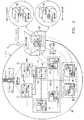
図3は、ハードウェア構成要素上にマップされる通信プラットフォーム10の概念構成要素を使用するシステム40構成を示す図である。
【0017】
ハードウェア構成の点から見ると、ノードは、クライアントまたはサーバとして作用することができる、ネットワーク(イーサネットなど)内部のコンピュータプロセッサである。各ノードは、ノード上を動作するオペレーティングシステムの単一のインスタンスを有する。ノード内部のプロセッサは、オペレーティングシステムに依存しているため、互いに独立して動作することができない。サイトにある各ノードは、プラットフォームマネージャまたはアプリケーションノードとして分類することができる。サイトは、ホストに接続された1つのノードまたはノードのグループからなっていてよい。プラットフォームマネージャノードは、冗長メートを有する。プラットフォームマネージャとそのメートは、アクティブ/待機モードまたはロード共有モードで動作することができる。
【0018】
システム40は8つのノードを有し、2つのプラットフォームマネージャノード(アクティブ42と待機43)と、6つのアプリケーションノード44〜49とを含む。呼出しがかけられた時間、または時間依存ルーティングに基づいて、電話呼出しを取り扱うためのアプリケーション50が、ノードにわたって配置される。アプリケーション50の構成可能エレメントセット52および54は、時間依存ルーティング機能を供給する分散構成要素である。各構成可能エレメントセット52および54は、特定の時間区域に関するUNIX実行可能プログラムまたは構成可能エレメントのソフトウェアプロセスを含む。図示されるように、アプリケーション50は、単一のアプリケーションノード44〜49に常駐する必要はない。構成可能エレメントセットを、異なるノードにマップすることが望ましい。これにより、構成可能エレメントセットが構成されるノードの数を増加させることによって、アプリケーションを基準化することが可能になる。
【0019】
通信プラットフォーム内部アーキテクチャを、論理的区画分けおよび物理的区画分けの点から記述した。論理的区画分けは、図4に示されるように、通信プラットフォームを異なる機能領域に分ける。各機能領域は、組み合わさって1つの特定のシステム機能を提供する、クラスの結合性グループを含む。物理的区画分けは、システムのコンテキストの具体的なソフトウェアおよびハードウェア分解を記述する。通信プラットフォーム10によって提供されるサービスは、アプリケーションサービス60とコアサービス62との2つのグループに区画分けすることができる。アプリケーションサービスは、情報および問題報告(IPR)/警報64、統計65、辞書66、グラフィカルユーザインタフェース(GUI)67、およびホスト保守シミュレータ(HMS)を実施する、サービスを含むことができる。IPR/警報サービス64は、誤り状態および他の関連するシステム情報を、システムユーザに知らせるための標準機構を提供する。統計サービス65は、全システム測定データにアクセスし、かつ収集されたデータに基づいて報告を生成するための方法を提供する。辞書サービス66は、データ記憶装置(持続、共有、または個人)をサポートして、データにアクセスするように構成されたクラスを提供する。グラフィカルユーザインタフェース67は、GUIアプリケーションを構築するための基本抽象を提供し、システムユーティリティ、およびシステム自体、例えばxターム(xterm)ウィンドウやオペレーティングシステムユーティリティプログラムにアクセスする。ホスト保守シミュレータサービス75は、システム内部にノードが1つしかないとき、または接続するためのホストがないときに、通信プラットフォームとインタフェースする方法を提供する。プラットフォームの制御および操作が可能になるのは、ホストを介してである。
【0020】
コアサービス62は、ネットワーク管理68、ノード管理69、分散オブジェクト70、通信72、共通機能73、およびイベント取扱い74を実施するサービスを含むことができる。ネットワーク管理サービス68は、ネットワークアクティビティ、例えばノードおよびネットワークレベル障害処理の構成を指図する。ノード管理サービス69は、ノードレベルプロセス、例えばノードステータス報告およびリンク管理を指図する。分散オブジェクトサービス70は、多重処理環境における、オブジェクトベースの通信用分散データベースリポジトリを提供する。通信サービス72は、プラットフォームの外部のプロセス間リンクにわたってメッセージを取り扱うための機構を提供する。共通サービス73は、通信プラットフォーム上、またはその内部で動作するように構成されるプロセスの迅速な開発を補助するために、プログラミングツールのライブラリを提供する。イベントサービス74は、タスクに重要な特定のアクションを開始し、終了し、および/または分散する能力を提供する。
【0021】
最低限、通信プラットフォームは、コアサービス全てを提供する。高レベルアプリケーションは、これらのサービスを使用して、より低いレベルの機能を実施する。
【0022】
さらに、図5に通信プラットフォームサービス、およびその依存関係を示す。開発者は、通信プラットフォームアプリケーションプログラムインタフェース14を介してコアサービスおよびアプリケーションサービス全てにアクセスする。また開発者は、必要があれば、オペレーションシステム、ネットワーク、および第三者ソフトウェア/ハードウェアにアクセスすることもできる。プロセス間オブジェクトベース通信は、通信サービス72によって取り扱われる。ほとんどのコアサービスおよびアプリケーションサービスが、通信サービス72および共通サービス73に依存してそれぞれの機能を実施する。グラフィカルユーザインタフェースサービス67は、通信サービス72のみに依存する場合がある。図5の矢印は、サービス間の依存関係を示す。
【0023】
図6は、アプリケーション層80およびコア層82を含む、通信プラットフォーム10の物理的区画分けの図である。コアサービス62を含むコア層82は、通信プラットフォームのあらゆるインスタンスのために存在する。コア層82は、通信プラットフォームAPI14、プロセス間通信機構、イベント機構、およびプラットフォーム管理を含む。通信プラットフォームアプリケーション層80は、垂直および水平の区画を有する。垂直方向では、各通信プラットフォームアプリケーションプロセスが、アプリケーションの主セット84の一部、またはそうでないものとして分類される。非主セットプロセスは、主セットプロセスに依存する。水平方向では、通信プラットフォームアプリケーション80は、必要に応じて、または任意に分類される。任意のアプリケーションには、IPR/警報パッケージ86、データ収集パッケージ87、辞書管理システムパッケージ88、およびホスト保守シミュレーションパッケージ89が含まれる。
【0024】
以下、通信プラットフォームサービスをより詳細に説明する。
【0025】
ネットワーク管理サービス
ネットワーク管理サービス68は、ネットワークエレメントの共通管理ビューを提供する。これは、サービスからサーバノードを除去する、サービスにサーバノードを復元する、サービスからアプリケーションを除去する、サービスからアプリケーションを復元する、アプリケーションをイネーブルまたはディスエーブルする、分散アプリケーションのステータスを保守する、サーバノード状態およびステータスを保守する、アプリケーションステータス変更を報告するなど、ネットワークエレメントノード上の高レベル動作を実施する役割をする。ネットワーク管理サービス68は、ネットワークプラットフォームマネージャ(NetPM)、ネットワークシステム保全サブシステム(NetSI)、および構成マネージャ(ConfigMgr)を含む。図7Aは、アクティブプラットフォームマネージャノード100を、対応する、またはメートされた待機プラットフォームマネージャノード102と共に示すブロック図である。各プラットフォームマネージャノードは、ネットワークプラットフォームマネージャ104、ネットワークシステム保全サブシステム106、および構成マネージャ108を含む。プラットフォームマネージャネットワークテストドライバ110が、ネットワークレベルテストを提供する。
【0026】
ネットワークプラットフォームマネージャ(NetPMMain)
ネットワークプラットフォームマネージャのためのクラス名は、NetPMである。NetPMは、プラットフォームリソースの管理機能を提供する役割をする。プラットフォームは、テレフォンカードやクレジットカードの検証など、特定のサービスに関する処理能力を提供する、複数のノードまたはサーバからなる分散システムである。サーバによって提供されるサービスは、ノードに常駐する構成可能エレメントによって決定される。NetPMは、プラットフォームに関連する全ての構成データを管理する。構成データは、サーバのTCP/IPアドレスなどハードウェアに関する情報、サーバや照会ステータスなどステータス情報、アプリケーションタイプなどソフトウェア構成情報、ノード名、および個々の構成要素エレメントに関する情報を含む。
【0027】
NetPMは、以下の構成情報を保守する。これらの情報は、初期設定中にNetPMによって収集される。
【0028】
・構成可能エレメント記述子情報
プラットフォームの各構成可能エレメントに関する構成情報を提供する。NetPMは、様々なタイプの構成可能エレメントに関する情報を含むディスクファイルからこれらを検索する。
【0029】
・アプリケーション情報
各アプリケーション(サービス)に関する構成情報を提供し、アプリケーションのステータスを計算する際に使用できる。NetPMは、プラットフォーム内の全てのアプリケーションに関する情報を含むディスクファイルからこの情報を検索する。
【0030】
・プロセッササービスグループ情報
プロセッササービスグループに関する構成情報を提供し、プロセッササービスグループステータスを計算する際に使用することができる(プロセッササービスグループは、同じアプリケーションを提供するプロセッサのグループ、すなわちCCD、CCLを表す)。NetPMは、プラットフォーム内の全てのプロセッササービスグループに関する情報を含むディスクファイルからこれらを検索する。
【0031】
・サーバ情報
プラットフォーム内の全てのサーバに関する特定の情報を提供する。NetPMは、ConfigMgrにこの情報を要求して、そこから検索する。ConfigMgrはまず、プラットフォームマネージャノードに関するサーバ情報をNetPMに提供する。その後ConfigMgrが、現行サーバがアクティブプラットフォームマネージャであると判定した場合、プラットフォーム内の残りのサーバに関する情報を局所NetPMに提供する。そうでない場合(待機プラットフォームマネージャ)は、NetPMはそれらの情報を、ConfigMgrからでなく、メートから検索する。
【0032】
これらの情報を収集している間に誤りが検出された場合、NetPMは適切なIPRを発行して、終了する。
【0033】
NetPMは、全ての構成データを管理するためにNetMAPオブジェクトを使用する。NetPMはまた、持続辞書を使用して、プラットフォームマネージャリセットにわたってサーバステータス、照会ステータス、およびスケジュールされたアクション情報を保持する。この辞書を管理するために、ディスクファイル辞書オブジェクトが使用される。NetPMは、2つのプラットフォームマネージャサーバ間の構成データの保全性を保守する役割をする。NetPMは、持続辞書、データベース等化、および監査を使用して、データの保全性を保守する。
【0034】
アプリケーションステータスは、プロセッササービスグループステータスに基づいて決定される。プロセッササービスグループステータスの決定には、以下の基準が使用される。
【0035】
・PSG_DISABLED
プロセッササービスグループ内の少なくとも設定数のサーバが、ディスエーブル状態にある。
【0036】
・PSG_INACTIVE
各プロセッササービスグループ内の少なくとも1つのサーバが、待機状態にあり、どれもアクティブ状態でない。
【0037】
・PSG_ACTIVE_MINIMAL
プロセッササービスグループ内のいくつかのサーバのみが、アクティブ状態にある。
【0038】
・PSG_ACTIVE
プロセッササービスグループ内の設定数のサーバが、アクティブ状態にある(注:この数は、PSG_ACTIVE_MINIMALにおいてアクティブでなければならないサーバの数よりも大きくなる)。
【0039】
アプリケーションステータスは、以下の基準を使用して導出することができる。
【0040】
・AP_DISABLED
所与のアプリケーションに関して、少なくとも設定数のプロセッササービスグループが、PSG_DISABLEDのステータスを有する。
【0041】
・AP_INACTIVE
所与のアプリケーションに関して、少なくとも1つのプロセッササービスグループが、PSG_INACTIVEのステータスを有し、どのプロセッササービスグループも、PSG_ACTIVEのステータスを有しない。
【0042】
・AP_ACTIVE_MINIMAL
所与のアプリケーションに関して、設定数のプロセッササービスグループが、PSG_ACTIVE_MINIMALのステータス、またはそれより高い(PSG_ACTIVE)ステータスを有する。
【0043】
・AP_ACTIVE_PARTIAL
所与のアプリケーションに関して、設定数のプロセッササービスグループが、PSG_ACTIVE_MINIMALのステータス、またはそれより高い(PSG_ACTIVE)ステータスを有する(注:AP_ACTIVE_PARTIAL状態に必要なプロセッササービスグループの数は、AP_ACTIVE_MINIMALにおけるプロセッササービスグループの必要数よりも大きい)。
【0044】
・AP_ACTIVE
所与のアプリケーションに関して、設定数のプロセッササービスグループが、PSG_ACTIVEのステータスを有する(注:AP_ACTIVE状態に必要なプロセッササービスグループの数は、AP_ACTIVE_PARTIALにおけるプロセッササービスグループの必要数よりも大きい)。
【0045】
NetPMは、各サーバノードに関するステータス変更のトラックを保持し、それらを得るとき、プロセッササービスグループのステータスを決定し、変更があった場合は、ノードに関する新しいアプリケーションステータスを決定し、この変更をConfigMgrに知らせる。
【0046】
NetPMは、アプリケーションステータスに関する送信請求された更新および自律的更新を提供する。自律的更新では、まず、アプリケーションプログラムが、NetPMに機能を登録して、特定のアプリケーションタイプ(CCDまたはCCL)に関する更新を受け取る。NetPMが、NodePMからサーバまたは照会ステータスの変更を受け取ると、アプリケーションステータスが計算され、登録された機能が、古いアプリケーションステータスと新しいアプリケーションステータスで呼び出される。アプリケーションステータスは送信請求されることができ、その間、NetPMは、要求するプロセスに、NetMAPに保存されたアプリケーションステータスの最新の計算値を返す。
【0047】
NetPMは、特に2つの別名オブジェクトの使用によって、NetPMと通信することを望む他のプロセスに、2組のルーティングオプションを提供する。NetPMは、局所および大域アクティブ待機オプションを提供する。局所オプションでは、全てのNetPMクライアント要求が、クライアントオブジェクトとして同じノードにあるNetPMサーバオブジェクトに送られる。大域アクティブ待機オプションでは、全てのNetPMクライアント要求が、大域的に(すなわち、場合によってはノード間で)使用可能なアクティブNetPMサーバオブジェクトに送られる。
【0048】
NetPMは、多数のサーバ構成データに関して、1組の読取機能および書込機能を提供する。これらには、スケジュールアクションデータ、プラットフォームマネージャアクティブステータスデータ、サーバステータスデータなどのための、読取機能/書込機能が含まれる。NetPMは、構成可能エレメント記述データに対する直接読取/書込動作を提供しない。
【0049】
NetPMはまた、大部分のサーバ構成データを初期設定するための機能を提供する。この機能は、入力としてServerInfoMsgオブジェクトを予想する。
【0050】
NetPMは、特定の構成アクション(グレースフル中止、即時中止、グレースフルダウングレード、および復元)が特定のサーバ上で行われるようにする1組の機能を提供する。
【0051】
NetPMは、特定のサーバについてサーバステータスを変更することができる機能を提供する。
【0052】
NetPMは、特定のサーバ上での照会処理をイネーブルする、かつディスエーブルするための機能を提供する。
【0053】
NetPMは、サーバステータスを「報告」し、ステータス変更を照会する複数の機能を提供する。これらのルーチンは、NetMAPに新しいステータス情報を保存し、ConfigMgrソフトウェアにその変更を通知し、プラットフォーム内の全てのNodePMソフトウェアに、その変更をブロードキャストする。
【0054】
NetPMは、サーバネットワーク内部の時間同期をする役割もする。時間同期は、図7Bに示されるように、3つの主要部からなる。第1の部分は、アクティブプラットフォームマネージャ100が、その局所時間をホストの時間と等しくする部分である。これは、ホスト(110)の時間を使用可能な形式に変換すること、およびプラットフォームマネージャノード100および102上のNodePM112に、adjtime機能を実施するように知らせて、ホスト110と一致するようにクロックを調節することを含む。NetPM104はまた、時間メッセージを受け取ったときに、ホストチッカークラスに新しいホスト時間を知らせる。ついで、xntpプロセス120が、アプリケーションノード(121)の時間を、プラットフォームマネージャノード100および102の時間と同期させる。各プラットフォームマネージャノード100および102は、xntpマスタ時間源として構成される。アプリケーションノード121上のxntpデーモンスレーブ122が、プラットフォームマネージャノード100および102上のマスタxntpデーモン120の1つを選択して、同期を保つ。最後に、非送信請求時間設定メッセージが、ホスト110から受け取られると、ネットワークの時間が、受け取られた時間と等しくなる。
【0055】
最後に、NetPM104は、新たにブートされたノードに、プラットフォーム内の全てのサーバの持続サーバ構成データを提供する機能を提供する。NetPM104は、構成可能エレメントである。NetPM104は、NodePMがNetPMの実行を制御するために必要とする、Remove(除去)、Restore(復元)、およびGetStatus(ステータス取得)というカプセル化されていない操作を提供する。監査タイマが始動すると、NetPMTimerHandlerが呼び出される。これが提供サービスループを打ち切り、NetPM機能SettimeToVerifyを呼び出して、監査を開始する。
【0056】
NetPM104は、それ自体の制御のスレッドを伴うオブジェクトである。NetMAPリストを構築した後、要求を待つ無限ループに入る。サーバのサービスまたは照会ステータスの変更があるときはいつでも、NetPM104は、ConfigMgr108に通知する。また、NetPM104は、これらのステータス変更を、プラットフォーム内の全てのNodePM112に送る。NetPM104は、特定のNodePM112に、照会処理をイネーブル、またはディスエーブルするように通知する。NetPM104は、サービスステータス同期機能を提供する。NetPM104は、プラットフォーム内のサーバに関するIPU情報を構築し、その情報を、BootNotifyメンバ機能内の特定のNodePM112に渡す。NetPMは、サービスのダウングレードに対する全ての構成要求(すなわち、GraceDown、ImmedDown、GraceHalt、およびImmedHalt)において、サーバの所望の状態を、特定のNodePM112に通知する。サーバ復元が要求されたとき、NetPM104は、いくつかのことを行う。まずNetPM104は、特定のNodePM112からサーバの現行ステータスを取得する。第2に、返されたステータスがサービス外/最小ソフトウェアである場合、関連するNodeSpecInfoを、特定のNodePM112に送る。第3にNetPM104は、関連する構成可能エレメント記述子情報を、特定のNodePM112に送る。最後に、NetPMが特定のNodePMにサービスを復元するように知らせる。
【0057】
ネットワークシステム保全(NetSIMain)
ネットワークシステム保全(NetSI)サブシステム106は、ネットワークエレメントに関する監視および回復操作を提供する。これは、ネットワーク監視および回復を実施する役割をする。ネットワークシステム保全によって実施される操作には以下のものがある。
【0058】
− プラットフォームマネージャアクティブ/待機ステータス監視
− ノード故障報告相関関係
− 故障ノード回復アクション
ネットワークシステム保全のクラス名は、NetSIである。NetSI106は、プラットフォームマネージャに関するネットワークシステム保全性を管理する。NetSI106は、障害ノード上のNodeSIから、サーバダウングレードおよび通信障害の通知を受け取る。NetSI106は、NodeSIによって与えられるデータに基づき、どのようなアクションをとるべきか決定する。ノードがダウングレードを示す場合、NetSIは適切なアクションをとって、ネットワークレベルから所望のダウングレード状態にノードをダウングレードする。ノードが通信障害を示す場合は、NetSI106は前もって受け取ったデータから、(あるとしたら)どのノードが障害になっているか判定し、必要であれば、その障害ノードをダウングレードするようにアクションを行う。NetSIがノードに対してダウングレードが必要であると判定したとき、NetSIは、ダウングレードを行うために適切なNetPM操作を呼び出す。NetSIは、アクティブステータスの変更が必要な場合は、アクティブステータスを設定するために適切なNetPM操作を呼び出す。ダウングレードを行うためにNetPMが呼び出された後、特定のノードに関してステータスが変更していることをConfigMgrに通知する。これにより、ノードがダウングレードされたという通知をホストがすぐに受けることが可能になる。次いで、NetSIは、ステータス変更とその理由を示す、ネットワーク構成報告にエントリを書き込む。NetSIは、ノードの現行状態に基づいて、正当なサービス状態にノードをダウングレードする。
【0059】
NetSIは、通信障害リストを含む。このリストは、受け取られた各通信障害報告の報告サーバノード名および問題サーバノード名を保持する。通信障害報告が受け取られると、リストは、問題ノードに関する他の報告をサーチされる。見つからなかった場合、障害情報がリストに追加される。NetSIはまた、ダウンステータス情報リストも含む。ノードがサービス外であることをNodePMが示し、ノードが休止されていることをNetPMステータスが示さないとき、ダウンステータス情報エントリが、休止されたIPUのノード名を伴って作成される。タイマが作成され、ダウンステータス情報がリストに追加される。後に、(タイマが切れる前に)NodePMがそのノードに関してより高いステータスを示す場合、ダウンステータス情報エントリがリストから消去され、さらなるアクションは行われない。
【0060】
NetSIは、両PMのステータス状態を定期的に監査する。無効状態が存在する場合、NetSIは、アクティブステータスを是正状態に設定することによって、ステータスを是正することを試みる。他のプロセスも、プラットフォームマネージャステータス状態を監査するようNetSIに要求することができる。
【0061】
NetSIは、「両方に送る(send to both)」ロード共有概念の下で動作する。プラットフォームマネージャノードが共に作動状態にある場合、各プラットフォームマネージャノードにおける各NetSIプロセスが、NodeSI要求を受け取る。各NetSIプロセスは、プラットフォームのアクティブ/待機状態および障害サーバに基づいて、要求を取り扱うべきかどうか判定する。アクティブプラットフォームマネージャのNetSIプロセスは通常、必要とされるアクションを行い、一方、待機プラットフォームマネージャは情報を廃棄する。しかし、障害ノードがアクティブプラットフォームマネージャである場合、待機プラットフォームマネージャは、(有効であれば)それ自体をアクティブに設定し、要求アクションをとって、他のプラットフォームマネージャノードをダウングレードする。
【0062】
NetSI操作が呼び出されるたびに、NetSIはまず、アクティブプラットフォームマネージャであるか待機プラットフォームマネージャであるかを判定する。アクティブである場合、ターゲットノードがそれ自体であり、かつメートがサービス中であるときを除いて、NetSIは、全ての状態に関する要求を処理する。待機状態の場合、NetSIは、ターゲットノードがメートであるときを除いて、全ての状態に関する要求を廃棄する。
【0063】
初期設定中、NetSIは、NodePMからメートのノード名、およびそれ自体のサーバおよびメートサーバのサーバ識別子を要求する。情報を要求する前、NetSIは、NodePMのステータスについてポーリングを行い、NodePMが読み取られて提供されるまでは、ノード名およびサーバ識別子を要求しない。NetSIは、この情報が適切に受け取られるまでは、サービスを提供するための準備をされない。
【0064】
NetSIは、コマンドラインパラメータDWN_RPT_FILEを使用して、ネットワーク構成(ダウングレード)報告ファイル名の名前を得る。このパラメータが指定されない場合、どの報告エントリもダウングレードから作成されない。
【0065】
図7Cおよび7Dを参照すると、ノード管理とネットワーク管理のプロセス相互作用が示される。定期監視モニタ(ConMon)は、アプリケーションノード136上を動作するオブジェクトのインスタンスである。ConMon132は、障害プロセスまたは故障構成可能エレメントを検出し、サービス管理プロセスプログラム134に通知する。サービス管理プロセス134は、構成可能エレメント故障によってプロセスがしきい値レベルを下回るかどうかを判定する。下回らない場合、サービス管理プロセス134は、構成可能エレメントを再始動する。しかし、構成可能エレメントがしきい値レベルを下回る場合は、サービス管理プロセス134は、構成可能エレメントステータス変更メッセージを生成して、その通知をNodeSI130に転送する。NodeSIは、構成可能エレメントステータス変更を、NodePM112に転送する。NodePM112は、構成可能ステータス変更がノードの実行レベルに影響を及ぼして、ノードのダウングレードを行う可能性があるかどうかを判定する。ノードが除去される場合、NodePM112は、サービス管理プロセス134に命令を提供して、ダウングレードされた状態を達成するのに必要な全ての構成可能エレメントを除去する。NodePM134は、NetPM104にノードステータス変更を通知した。NetPM104は、ノードステータス変更が、プロセッササービスグループおよびアプリケーションステータスに影響を及ぼすかどうかを判定するために計算を行う。NetPMの計算はまた、ノードをサービス中から最小設定(min−set)へ移し、それを再び復元するなどの自動アクションを、ノードに対して行うべきかどうかを判定する。ノードが移される場合、ノードステータス変更は、NetPMからConfigMgr108に転送される。ConfigMgrは、ノード、プロセッササービスグループ、およびアプリケーションに関する状態変更をホスト140に通知する。これらの状態変更は、報告に表示または印刷することができる。
【0066】
特に、各NetSIは、ダウングレード要求を取り扱うべきかどうか判定する。要求を取り扱う場合、ターゲットサーバのステータスが検索される。ターゲットサーバがまだ休止されていない場合、サーバは、IPUステータスに基づいて、適切なステータスにダウングレードされる。IPUステータスがサービス外である場合、NetSIは、NetPMの即時休止操作を呼び出して、ターゲットノードを自動休止または手動休止する。IPUステータスがサービス外最小(OS−MIN)である場合、NetSIは、OS−MINにターゲットノードをダウングレードするために、NetPMの即時ダウングレード操作を呼び出す。IPUステータスがサービス中にディスエーブルされている場合、NetSIは、ターゲットノードに関する照会ステータスをディスエーブルするように、NetPMのディスエーブル照会操作を呼び出す。いずれにせよ、ターゲットノードがアクティブプラットフォームマネージャである場合、NetsSIがアクティブステータスを更新する。また、ターゲットノードが局所サイトの一部である場合、NetSIは、ステータス変更が生じたことをConfigMgrを介してホストに知らせ、ターゲットサーバのプロセッササービスグループを回復すべきであると判定した場合は、プロセッササービスグループの回復を(ConfigMgrを介して)開始する。次いで、NetSIは、ネットワーク構成報告ファイルにエントリを書き込み、ノードが障害を報告したためにステータス変更が生じたことを示す。
【0067】
NodeSIは、2つのノード間で起こった通信障害をNetSIに知らせる。NetSIは、以前の情報受信(があればそれ)に基づいて、障害を記憶するか、障害にアクションを起こす。各NetSIは、報告ノードおよび問題ノードのステータスを判定する。いずれかのサーバが休止されている場合、データの保全性を保証することができないので、通信障害報告が廃棄される。どちらのサーバも休止されていない場合、通信障害リストが、問題ノードに関する他の報告をサーチされる。問題ノードに関する報告が見つからなかった場合、通信障害リストエントリが、サーバ情報と共にリストに追加される。問題ノードの他の報告が見つかり、他の報告サーバがそれを報告していた場合、その問題サーバが、ダウングレード処理を行うためにセットアップされる。サーバをダウングレードすべきかどうかについて決定が下されると、NetSIは、(アクティブ状態、およびターゲットサーバがそれ自体であるか否かに基づいて)それを取り扱うべきかどうか判定する。ダウングレードを取り扱うべき場合、NetSIは、NetPMの即時休止操作を呼び出して、問題ノードを自動休止または手動休止する。休止すべきサーバがアクティブPMである場合は、それに応じて、ノードを休止する前に、アクティブステータスを更新する。また、ターゲットが局所サイトの一部である場合、NetSIは、ステータス変更が生じていることを、ConfigMgrを介してホストに知らせ、ターゲットサーバのプロセッササービスグループを回復すべきであると判定された場合、(ConfigMgrを介して)プロセッササービスグループの回復を開始する。NetSIはまた、ネットワーク構成報告ファイルにエントリを書き込み、通信障害により休止されたことを示す。
【0068】
構成マネージャ(ConfigMgr)
構成管理サブシステム(クラス名:ConfigMgr)は、SCPホストとサーバ構成要素との間に制御インタフェースを提供する。サーバネットワーク上で行うことのできるすべての動作は、このインタフェースに定義される。構成管理サブシステムは、以下の特徴を与える。
【0069】
− ホストとサーバとの間の制御メッセージインタフェース
− 有効な動作に対する状態機械
− 要求によってネットワーク管理を駆動する
− 動作のタイミング/タイムアウトを制御する
ConfigMgrは、プラットフォームマネージャに対する、サーバ構成制御を管理する。ConfigMgrは、CONFIGCTL、MAINT、APLCTL、ROUTINGCTLの論理リンク上で送信されたホストメッセージを受け取り、それぞれを、そのメッセージidおよびタイプに基づいて処理する。ホストが応答または報告を送るように要求する場合、ConfigMgrは、必要な応答を決定し、必要な報告情報を取り出し、それをホストに送り返す。ConfigMgrは、以下のメッセージを扱う。
【0070】
・APPL_STATUS_MSG
・ASPEC_MSG
・CONFIGURE_SERVER_MSG
・PSG_INFO_MSG
・PSG_STATUS_MSG
・QUERY_PROCESSING_MSG
・RESET_SERVER_MSG
・ROUTING_INFO_MSG
・SCHED_ACTION_CTL_MSG
・SERVER_INFO_MSG
・SERVER_STATUS_MSG
・TEST_SERVER_MSG
・TIME_MSG
ConfigMgrはまた、ホストからサーバおよび時間の情報を取り出すための動作を、プラットフォームマネージャに提供する。ConfigMgrはまた、サーバのステータス変化をホストに通知する動作も提供する。ホスト指令メッセージの処理中、ConfigMgrは、ホストからの応答または特定のサーバからの状態変化を待機しなければならない時がある。ConfigMgrは、これらの待機に関して非ブロッキング原理を使用する。ConfigMgrは、停止してイベントの発生を待機するのではなく、所望の応答またはステータスを保留待ち行列(PendingQueue)上にセーブし、通常の、別のホストメッセージの処理を継続するか、またはクライアントにサービスを提供する。所望の応答またはステータスが発生すれば、適切な手続きが呼び出されて、ホスト指令メッセージの処理が再開される。指定の制限時間内に所望の応答が到着しない、あるいは所望のステータスが発生しない場合は、故障手続きを呼び出して、ホスト指令メッセージの処理をクリーンアップし、必要に応じてIPRを発行する。
【0071】
ホスト指令メッセージの処理に加え、ConfigMgrには、ステータス変化の発生時に、ホストに通知することも必要とされる。ConfigMgrは、ステータス変化を通知されると、ステータス保留待ち行列を検査して、それがステータス変化の発生を待機しているかどうかを判定する。待機している場合は、保留待ち行列成功動作が行われる。そうでない場合は、ConfigMgrは、ホストにサーバステータスメッセージを送る。ホスト応答メッセージの処理中、ConfigMgrは、ホスト応答保留待ち行列(HostPendQueue)を検査して、それが応答を待機しているかどうかを判定する。待機している場合は、保留待ち行列成功動作が行われる。そうでない場合は、ConfigMgrは、ホストからのその応答メッセージを破棄する。プラットフォームマネージャノードがOS−MIN状態にブートされているとき、それはそのメートを監査し、そのメートのステータスを決定する。メートのプラットフォームマネージャノードが存在しない場合は、メートのステータスは自動的に休止に設定される。同様の監査は、サービスサーバノード(PM以外のノード)上でも行われ、それらのステータスが決定される。
【0072】
ConfigMgrは、サブシステムが登録して特定のアプリケーションに対するルーティング情報を提供することのできる登録機能を有する。ホストがアプリケーションに関するルーティング情報を要求すると、ConfigMgrは、登録された適切なサブシステム(もし存在すれば)に、ルーティング情報の提供を要求する。
【0073】
構成サーバメッセージ(ConfigServerMsgs)は、行われるサービス(すなわち休止、ダウングレード、復元、ブート)の性質のために、特別な処理を要求する。ホストメッセージが両方のプラットフォームマネージャサービスに送られるため、1つのプラットフォームマネージャノードだけがその要求を処理することが保証されるように配慮されなければならない。これには、プラットフォームマネージャノードおよびそのメートのサーバ状態を検査することが必要となる。プラットフォームマネージャノードのサーバ状態、ならびに、ConfigServer要求がプラットフォームマネージャノードへのものか、そのメートへのものか、それともサービスサーバへのものであるかとに基づいて、異なる動作がとられる。2つの有限状態機械(PMCfgSvrFSMおよびSvcCfgSvrFSM)が、異なる状態によって駆動される全ての動作を管理する。
【0074】
PMCfgSvrFSMは、プラットフォームマネージャアプリケーションサーバに対する復元、休止、再同期化、ダウングレード、ブートを扱う有限状態機械である。この機械は、要求がそれ自体へのものか、それともそのメートへのものかと、それ自体のステータスと、そのメートのステータスと、要求されたイベント(休止、ダウングレード、復元など)とに基づいて、その要求を処理する。検査されるプラットフォームマネージャサーバ状態は、Halted(自動)、Halted(手動)、XOS−MIN、AOS−MIN(自動)、MOS−MIN(手動)、In−Svcである。In−Svcの場合、アクティブ/待機ステータスが検査されて、サーバがアクティブであるか待機であるかが判定される。有効なイベントは、復元(Restore)、グレースフル休止(Graceful Halt)、即時休止(Immediate Halt)、グレースフルダウングレード(Graceful Downgrade)、即時ダウングレード(Immediate Downgrade)、グレースフルブート(Graceful Boot)、即時ブート(Immediate Boot)、ホスト再同期化(Host Resync)である。
【0075】
イベントは、どのプラットフォームマネージャノードが要求を処理することになるかを決定するために重要である。復元が要求される場合、通常、復元されることになるプラットフォームマネージャノードが、その復元を処理する(すなわち、プラットフォームマネージャノードがそれ自体を復元する)。休止されているプラットフォームマネージャサーバの復元要求を処理する場合は、休止されたサーバのメートが(可能ならば)、拒否(Denial)応答をホストに送り返す。休止、ダウングレード、またはブートがプラットフォームマネージャノードに要求されると、プラットフォームマネージャノードのメートは、休止されていない限りそれを処理する。メートが休止されているときは、プラットフォームマネージャノードがそれ自体で、その休止、ダウングレード、またはブートを処理する。休止、ダウングレード、またはブートの処理は、要求された動作を実際に行うこと、またはホストに拒否応答を送り返すことを伴う場合がある。休止、ダウングレード、またはブートの要求が拒否されなければ、ホストは、その動作が成功したとみなす。
【0076】
プラットフォームマネージャノードがそれ自体でブートを処理しなければならないとき、プラットフォームマネージャノードは、NetPMのGraceHaltまたはImmedHalt動作を(ブートタイプに基づいて)呼び出して、それ自体を休止状態にする。次いで、それが休止状態まで下げられているため、このノードに対する処理は完了する。(ホストが、そのサーバのリセットおよびブートを開始することになる。)休止、ダウングレード、またはブートが、最後のIn−Serviceプラットフォームマネージャノードに要求されると、フォースフラグが検査される。フォースフラグが設定されていなければ、要求は、「DENIED−LAST AMP」の応答と共に拒否される。フォースフラグが設定されていれば、休止、ダウングレード、またはブートが、最後のIn−Serviceプラットフォームマネージャノード上で行われる。
【0077】
プラットフォームマネージャノードに対してHost Resyncが要求されると、ターゲットプラットフォームマネージャサーバのメートは、休止されていない限りその要求を処理する。ターゲットプラットフォームマネージャサーバのメートが休止されている場合は、再同期化のためのプラットフォームマネージャノードがその要求を処理する。この要求の処理は、サーバステータスを、XOS−MINからAOS−MINに、またはMOS−MINに変更すること、あるいは、現在のステータスがXOS−MINでない場合に、その要求を拒否することを伴う。
【0078】
SvcCFgSvrFSMは、サービスアプリケーションサーバに対する復元、休止、再同期化、ダウングレード、ブートを扱う有限状態機械である。この機械は、動作を行うプラットフォームマネージャノードの状態、作用を受けるサービスサーバの状態、および要求されたイベント(休止、ダウングレード、復元など)に基づいて要求を処理する。検査されるサービス状態は、Halted(自動)、Halted(手動)、XOS−MIN、AOS−MIN(自動)、MOS−MIN(手動)、InSvcである。有効なイベントは、復元、グレースフル休止、即時休止、グレースフルダウングレード、即時ダウングレード、グレースフルブート、即時ブート、ホスト再同期化である。
【0079】
アクティブなプラットフォームマネージャノード(OS−MINまたはIn−Service)は、サービスサーバに対する構成サーバ要求を処理する。復元、休止、再同期化、またはダウングレードは、1つのプラットフォームマネージャが少なくともOS−MINにある限り、サービスサーバ上で許可される。サービスサーバに対する復元は、少なくとも1つのプラットフォームマネージャがIn−Serviceのときだけ許可される。どのプラットフォームマネージャノードもIn−Serviceでない場合、アクティブなプラットフォームマネージャノードは、DENY−AMP not In−Service応答をホストに送り返す。休止、ダウングレード、またはブートの要求が拒否されなければ、ホストは、その動作が成功したとみなす。
【0080】
休止、ダウングレード、またはブートが、アプリケーションの最後のIn−Serviceノードに要求されると、フォースフラグが検査される。フォースフラグが設定されていなければ、要求は、「DENIED−LAST SERVER IN Processor service group PROCESSING QUERIES」の応答と共に拒否される。フォースフラグが設定されていれば、休止、ダウングレード、またはブートが、アプリケーションの最後のIn−Serviceノード上で行われる。
【0081】
構成イベント(即時休止を除く)が処理されるときは常に、構成中(Under Configuration)フラグがチェックされる。構成中フラグが設定されていれば、要求は、「DENIED−SERVER UNDER CONFIGURATION」の応答と共に拒否される。ConfigMrgは、イベントの処理中に、構成中フラグを設定およびクリアする。その他のメッセージ(すなわちServerinfoMsg、ServerStatusMsg、TimeMsgなど)は、有限状態機械を必要としない。
【0082】
復元要求が拒否されないとき、ConfigMgrは、サーバに対してUnderConfigフラグを設定し、ConfigServerMsg「Action initiated(動作開始)」RESPONSEをホストに送り、サーバをIn−Serviceに復元するために、NetPMのRestoreISV動作を呼び出す。次いでConfigMgrは、復元処理を延期し、サーバがIn−Serviceになるように、サーバステータス保留待ち行列(Server Status PendingQueue)エントリを設定する。復元処理は、サーバステータスがIn−Serviceであるかまたはタイマが切れていることを、ConfigMgrが通知されるまで継続されない。ConfigMgrが、In−Serviceへのサーバステータス変化を通知されると、サーバ照会ステータスを検査することによって、復元処理が継続される。サーバの照会ステータスがDISABLED_SERVER_OOSであり、アクティブなサーバの数が、プロセッササービスグループのアクティブサーバ総数よりも少ない場合、ConfigMgrは、NetPMのEnableQuery動作を呼び出して、サーバの照会ステータスをイネーブルにし、現在の照会ステータスをPending(保留)に設定する。次いでConfigMgrは、サーバおよび照会ステータスの変化を通知するサーバステータスメッセージをホストに送る。サーバの照会ステータスをEnabledにするために、照会ステータス保留待ち行列(QueryStatus PendingQueue)エントリが設定される。次いで処理は、照会ステータスがイネーブルにされるか、あるいはタイマが切れるまで延期される。照会ステータスがEnabledに変化したことを、ConfigMgrが通知されると、復元処理は継続し、サーバステータスメッセージを送り、サーバに対する構成中フラグをクリアする。
【0083】
サーバステータスがIn−Serviceに変化する前にタイマが切れると、あるいは他のアプリケーションに対して要求したサーバ情報が受け取られないと、復元故障処理が開始される。故障処理は、グレースフルにサーバをOS−MINにダウングレードすること、IPRを発行すること、およびサーバに対する構成中フラグをクリアすることを含む。照会ステータスがEnabledに変化する前にタイマが切れると、復元処理は継続し、照会ステータスをDisabledに設定し、グレースフルにサーバをOS−MINにダウングレードし、サーバステータスメッセージを送り、IPRを発行し、サーバに対する構成中フラグをクリアする。
【0084】
グレースフル休止要求が拒否されないとき、ConfigMgrは、サーバに対するUnderConfigフラグを設定し、ConfigServerMsg「Action Initiated(動作開始)」RESPONSEをホストに送り、サーバを休止させるために、NetPMのGraceHalt動作を呼び出す。ノードがまだ休止されていない場合、ConfigMgrは休止処理を延期し、サーバがHaltedになるようにサーバステータス保留待ち行列エントリを設定する。次いでConfigMgrは、ホストによって休止が要求されたことを示すエントリをネットワーク構成報告に作成する。休止処理は、サーバステータスがHaltedであるかまたはタイマが切れていることを、ConfigMgrが通知されるまで継続されない。休止状態へのサーバステータス変化をConfigMgrが通知されると、休止処理は継続し、サーバステータスメッセージを送り、サーバに対する構成中フラグをクリアする。サーバステータスがHaltedに変化する前にタイマが切れると、休止故障処理が開始される。故障処理は、IPRを発行し、サーバに対する構成中フラグをクリアすることを伴う。
【0085】
即時休止要求が拒否されないとき、ConfigMgrは、サーバに対するUnderConfigフラグを設定し、このサーバに対するすべての保留中のサーバステータス変化をステータス保留待ち行列から除去し、サーバを休止させるためにNetPMのImmedHalt動作を呼び出す。ノードがまだ休止されていなければ、ConfigMgrは、休止処理を延期し、サーバがHaltedになるように、サーバステータス保留待ち行列エントリを設定する。次いでそれは、ホストによって休止が要求されたことを示すエントリを、ネットワーク構成報告に作成する。休止処理は、サーバステータスがHaltedであるかまたはタイマが切れていることを、ConfigMgrが通知されるまで継続されない。休止状態へのサーバステータス変化をConfigMgrが通知されると(あるいは休止が発行されたときにノードがすでに休止されていると)、休止処理は継続し、サーバステータスメッセージを送り、ConfigServerMgr「Successfully Completed(首尾よく完了)」RESPONSEをホストに送り、サーバに対する構成中フラグをクリアする。
【0086】
サーバステータスがHaltedに変化する前にタイマが切れると、休止故障処理が開始される。故障処理は、IPRを発行し、ConfigServerMsg「Action Failed(動作故障)」RESPONSEをホストに送り、サーバに対する構成中フラグをクリアすることを含む。
【0087】
グレースフルダウングレード要求が拒否されないとき、ConfigMgrは、サーバに対するUnderConfigフラグを設定し、ConfigServerMsg「Action Initiated(動作開始)」RESPONSEをホストに送り、サーバをダウングレードするためにNetPMのGraceDown動作を呼び出す。ノードがまだ所望のダウングレード状態になければ、ConfigMgrは、ダウングレード処理を延期し、サーバがOS−MINになるように、サーバステータス保留待ち行列エントリを設定する。次いでそれは、ホストによってダウングレードが要求されたことを示すエントリを、ネットワーク構成報告に作成する。ダウングレード処理は、サーバステータスがOS−MINであるかまたはタイマが切れていることを、ConfigMgrが通知されるまで継続されない。OS−MIN状態へのサーバステータス変化をConfigMgrが通知されると(あるいはノードがすでにその状態であれば)、ダウングレード処理は継続し、サーバステータスメッセージを送り、サーバに対する構成中フラグをクリアする。サーバステータスがOS−MIN状態に変化する前にタイマが切れると、ダウングレード故障処理が開始される。故障処理は、IPRを発行し、サーバに対する構成中フラグをクリアすることを伴う。
【0088】
即時ダウングレード要求が拒否されないとき、ConfigMgrは、サーバに対するUnderConfigフラグを設定し、サーバをダウングレードするためにNetPMのImmedDown動作を呼び出す。ノードがまだ所望のダウングレード状態になければ、ConfigMgrは、ダウングレード処理を延期し、サーバがOS−MINになるように、サーバステータス保留待ち行列エントリを設定する。次いでそれは、ホストによってダウングレードが要求されたことを示す、エントリをネットワーク構成報告に作成する。ダウングレード処理は、サーバステータスがOS−MINであるかまたはタイマが切れていることを、ConfigMgrが通知されるまで継続されない。OS−MIN状態へサーバステータス変化をConfigMgrが通知されると(あるいはノードがすでにその状態であれば)、ダウングレード処理は継続し、サーバステータスメッセージを送り、ConfigServerMsg「Successfully Completed(首尾よく完了)」RESPONSEをホストに送り、サーバに対する構成中フラグをクリアする。
【0089】
ステータスがOS−MIN状態に変化する前にタイマが切れると、ダウングレード故障処理が開始される。故障処理は、IPRを発行し、ConfigServerMsg「Action Failed(動作故障)」RESPONSEをホストに送り、サーバに対する構成中フラグをクリアすることを伴う。
【0090】
グレースフルまたは即時ブート要求が拒否されないとき、ConfigMgrは、サーバに対するUnderConfigフラグを設定し、ConfigServerMsg「Action Initiated(動作開始)」RESPONSEをホストに送る。ConfigMgrは、サーバに対するサーバステータスを検査し、サーバが休止状態でなければ、NetPMのGraceHaltまたはImmedHalt動作を呼び出す。休止動作が呼び出されると、処理は、サーバステータスが休止されているかまたはタイマが切れていることを、ConfigMgrが通知されるまで延期される。次いでConfigMgrは、ホストによってブートが要求されたことを示すエントリをネットワーク構成報告に作成する。
【0091】
OS−MIN状態へのサーバステータス変化をConfigMgrが通知されると(あるいはノードがすでにその状態であれば)、ダウングレード処理は継続し、サーバステータスメッセージを送り、ConfigServerMsg「Successfully Completed(首尾よく完了)」RESPONSEをホストに送り、サーバに対する構成中フラグをクリアする。サーバステータスがOS−MIN状態に変化する前にタイマが切れると、ダウングレード故障処理が開始される。故障処理は、IPRを発行し、ConfigServerMsg「Action Failed(動作故障)」RESPONSEをホストに送り、サーバに対する構成中フラグをクリアすることを伴う。
【0092】
グレースフルまたは即時ブート要求が拒否されないとき、ConfigMgrは、サーバに対するUnderConfigフラグを設定し、ConfigServerMsg「Action Initiated(動作開始)」RESPONSEをホストに送る。ConfigMgrは、サーバに対するサーバステータスを検査し、サーバが休止状態でなければ、NetPMのGraceHaltまたはImmedHalt動作を呼び出す。休止動作が呼び出されると、処理は、サーバステータスが休止されているかまたはタイマが切れていることを、ConfigMgrが通知されるまで延期される。次いでConfigMgrは、ホストによってブートが要求されたことを示すエントリを、ネットワーク構成報告に作成する。
【0093】
サーバが休止されているとConfigMgrが判定するとき、ConfigMgrは、ResetServerMsg要求をホストに送る。ConfigMgrは、ホスト応答待ち行列エントリを生成して、ホストからのResetServerMsg応答を待つ。次いで処理は、RESPONSEが受け取られるまで、あるいはタイマが切れるまで延期される。RESPONSEが受け取られると、ConfigMgrは、サーバステータス保留待ち行列エントリを設定して、サーバステータスがOS−MINになるのを待つ。タイマが切れる前にホストからの応答が受け取られなければ、IPRが発行され、構成中フラグがクリアされる。サーバステータスがOS−MINになると、ConfigMgrは、新しいサーバステータスを示すサーバステータスメッセージをホストに送り、構成中フラグをクリアする。サーバステータスがOS−MINになる前にタイマが切れると、ConfigMgrは、IPRを発行し、構成中フラグをクリアする。
【0094】
ホスト再同期化要求が拒否されないとき、ConfigMgrは、サーバステータスがXOX_MINであるかどうかを判定する。そうである場合、NetPMのSetServerStatus動作が呼び出されて、サーバステータスが適切な自動/手動OS_MIN状態に設定され、新しいサーバステータスを示すサーバステータスメッセージが送られ、ConfigServerMsg「Successful(成功)」RESPONSEがホストに送られる。サーバステータスがXOS_MINでない場合、IPRが発行され、ConfigServerMsg「Action Failed(動作故障)」RESPONSEがホストに送られる。
【0095】
アプリケーションステータスメッセージは、In−Serviceアクティブであるプラットフォームマネージャノードによって処理される。どのプラットフォームマネージャノードもIn−Serviceでない場合、OS−MINアクティブであるプラットフォームマネージャノードが、その要求を処理することになる。ApplStatusMsg REQUESTタイプメッセージをホストから受け取ると、ConfigMgrは、アプリケーション照会ステータスを決定し、現在のアプリケーション照会ステータスと共に、ApplStatusMsg S_REPORTをホストに送り返す。ConfigMgrは、サーバステータス変化が起こったとき、またはホスト構成サーバ要求の処理中に必要とされるとき、ApplStatusMsg U_REPORTタイプメッセージをホストに送る。
【0096】
ConfigMgrは、ApplsInfo.des記述子ファイル中の各アプリケーションに対する、ASPEC Data REQUESTメッセージをホストから受け取る。ConfigMgrは、NetPMに照会して、そのアプリケーションに対する情報をNetMAPから検索する。成功または故障を示す応答コードと共に、ASPEC Dataを含む応答メッセージが、ホストに送り返される。無効なアプリケーションId、ASPEC Data REQUESTメッセージ以外のメッセージ、または要求以外のメッセージタイプがある場合、IPRが発行される。
【0097】
プロセッササービスグループ情報メッセージは、In−Serviceアクティブであるプラットフォームマネージャノードによって処理される。どのプラットフォームマネージャノードもIn−Serviceでない場合、OS−MINアクティブであるプラットフォームマネージャノードが、その要求を処理することになる。
【0098】
PSGInfoMsg REQUESTタイプメッセージをホストから受け取ると、ConfigMgrは、プロセッササービスグループ情報を決定し、プロセッササービスグループ情報と共に、PSGInfoMsg S_REPORTをホストに送り返す。
【0099】
プロセッササービスグループステータスメッセージは、In−Serviceアクティブであるプラットフォームマネージャノードによって処理される。どのプラットフォームマネージャノードもIn−Serviceでない場合、OS−MINアクティブであるプラットフォームマネージャノードが、その要求を処理することになる。PSGStatusMsgREQUESTタイプメッセージをホストから受け取ると、ConfigMgrは、プロセッササービスグループ照会ステータスを決定し、現在のプロセッササービスグループ照会ステータスと共にPSGStatusMsg S_REPORTをホストに送り返す。ConfigMgrは、サーバステータス変化が起こったとき、またはホスト構成サーバ要求の処理中に要求があれば、PSGStatusMsg U_REPORTタイプメッセージをホストに送る。
【0100】
照会処理メッセージは、In−Serviceアクティブであるプラットフォームマネージャノードによって処理される。どのプラットフォームマネージャノードもIn−Serviceでない場合、OS−MINアクティブであるプラットフォームマネージャノードが、その要求を処理することになる。ConfigMgrは、QueryProcMsg DISABLE_SERVER、DISABLE_SERVER_FORCED、およびENABLE_SERVER要求タイプをホストから受け取る。このメッセージを処理する際、ConfigMgrは、EnableServer/DisableServer動作をNetPMから呼び出すことによって、ターゲットサーバに対する照会処理をイネーブル/ディスエーブルにすることを開始する。ConfigMgrは、サーバに対して照会ステータス保留待ち行列エントリを設定し、サーバに対する照会ステータスが所望の状態に変化するか、またはタイマが切れるまで、それ以上の処理を延期する。NetPMは、ConfigMgrのNtfyQryStatChange動作を呼び出すことによって、照会ステータスの変化をConfigMgrに通知する。ConfigMgrがこの動作を処理するとき、ConfigMgrは、サーバ照会ステータスの状態に対する照会ステータス保留待ち行列エントリを検査する。所望の照会ステータスを伴うエントリがあれば、適切な成功照会処理手続きが呼び出されて、QueryProcMsgの処理が再開される。QueryProcMsgに対する成功処理は、要求が成功であったことを示すQueryProcMsg RESPONSEをホストに送り返すこと、および必要であればプラットフォームマネージャノードに対するアクティブステータスを変更することを伴う。
【0101】
サーバ照会ステータスが所望の状態になる前にタイマが切れると、適切な故障照会処理手続きが呼び出されて、QueryProcMsgの処理が再開される。QueryProcMsgの故障処理は、IPRの発行、および要求が故障したことを示すQueryProcMsg REPONSEをホストに送り返すことを伴う。
【0102】
ConfigMgrは、サーバのブート処理中に、ResetServerMsg REQUESTタイプメッセージを送る。ホストがPMでないサーバに対するブートを要求するとき、ターゲットサーバが休止された後に、ResetServerMsg REQUESTが送られる。次いで、ConfigMgrはブート処理を延期し、ResetServerMsg RESPONSEタイプメッセージに対してホスト応答保留待ち行列エントリを設定する。ブート処理は、RESPONSEが受け取られるまで、またはタイマが切れるまで、継続されない。ConfigMgrが、ResetServerMsg RESPONSEタイプメッセージをホストから受け取ると、ConfigMgrは、ホスト応答保留待ち行列エントリ中のRestServerMsg RESPONSEに対する、ホスト応答保留待ち行列中のResetServerMsgRESPONSEに対するエントリがあるかどうかを検査する。ある場合は、適切な手続きが呼び出されて、ブート処理が完了する。
【0103】
ルーティング情報メッセージは、In−Serviceアクティブであるプラットフォームマネージャノードによって処理される。どのプラットフォームマネージャノードもIn−Serviceでない場合、そのメッセージは破棄される。ConfigMgrは、RoutingInfoMsg REQUESTタイプメッセージをホストから受け取ると、要求が承認されたことを示すRoutingInfoMsg RESPONSEをホストに送り返し、ルーティング情報を検索することを試みる。ルーティング情報が検索されると、ConfigMgrは、ルーティング情報と共に、RoutingInfoMsg S_REPORTをホストに送り返す。ConfigMgrは、別のサブシステムからルーティング情報を送るよう要求があると、RoutingInfoMsg U_REPORTタイプメッセージをホストに送る。ルーティング情報の送信要求を別のサブシステムから受け取ると、ConfigMgrは、ルーティング保留待ち行列を検査して、ホストが情報を要求したかどうかを判定する。そうである場合は、ConfigMgrは、ルーティング情報と共に、RoutingInfoMgr S_REPORTをホストに送る。そうでない場合は、ConfigMgrは、ルーティング情報と共に、RoutingInfoMsg U_REPORTをホストに送る。ConfigMgrは、U_REPORTをホストに送った後、RoutingInfoMsg ACK RESPONSEを送ることによって、データの受信を承認するためにホストを待機する。制限時間内にConfigMgrが応答を得ない場合、ConfigMgrは、アプリケーションルーティング情報を再度送るように、適切なサブシステムに要求する(ホストにデータを再送するようにするため)。NAK RESPONSEがホストから受け取られる場合、ConfigMgrは、ホストからの故障応答コードを示すIPRを発行する。
【0104】
計画的動作制御メッセージは、In−Serviceアクティブであるプラットフォームマネージャノードによって処理される。どのプラットフォームマネージャノードもIn−Serviceでない場合、OS−MINアクティブであるプラットフォームマネージャノードが、その要求を処理することになる。ConfigMgrは、SchedActCtlMsg SETタイプのメッセージをホストから受け取ると、NetPMのSetSchedAction動作を呼び出して、計画的動作(定期監視や包括的な監査など)を希望に応じてイネーブル/ディスエーブルにする。ConfigMgrは、設定が成功であったか否かを示す、SchedActCtlMsg RESPONSEタイプをホストに送り返す。ConfigMgrは、クライアントがホスト時間情報を得るのに使用することのできる、GetSchedActions動作を有する。この動作が呼び出されると、ConfigMgrは、SchedActCtlMsg REQUESTタイプメッセージをホストに送る。次いでConfigMgrは、ホストからの所望のSchedActCtlMsg S_REPORTに対する、ホスト応答保留待ち行列エントリを設定する。次いで、(GtSchedActionsの)処理は、S_REPORTが受け取られるまで、またはタイマが切れるまで延期される。計画的動作を受け取る前にタイマが切れた場合は、何の動作も行われない。ConfigMgrは、SchedActCtlMsg S_REPORTタイプメッセージをホストから受け取ると、SchedActCtlMsg S_REPORTに対するエントリが、ホスト応答保留待ち行列中にあるかどうかを検査する。ある場合は、ConfigMgrは、NetPMのSetSchedAction動作を呼び出して、計画的動作を希望に応じてイネーブル/ディスエーブルにする。
【0105】
サーバ情報メッセージは、In−Serviceアクティブであるプラットフォームマネージャノードによって処理される。どのプラットフォームマネージャノードもIn−Serviceでない場合、OS−MINアクティブであるプラットフォームマネージャノードが、その要求を処理することになる。ConfigMgrは、プラットフォームマネージャサーバの初期設定処理および復元処理中に、ServeInfoMsg REQUESTおよびREQUEST ALLタイプメッセージをホストに送る。メッセージの送出後、ConfigMgrは、タスクの処理を延期し、ServerInfoMsg S_REPORTタイプ(および/または、REQUEST ALLが使用された場合は、COMPLETEタイプ)に対する、ホスト応答保留待ち行列を設定する。初期設定処理および復元処理は、必要とされるサーバ情報が得られるまで、またはタイマが切れるまで継続されない。初期設定中、(情報が得られる前に)タイマが切れると、ConfigMgrは、情報が得られるまで、ServerInfoMsg REQUESTまたはREQUEST ALLを再送する。プラットフォームマネージャサーバの復元中、(情報が得られる前に)タイマが切れると、ConfigMgrは、復元が故障したというIPRを発行する。
【0106】
ServerInfoMsg S_REPORTおよびCOMPLETEメッセージをホストから受け取ると、ConfigMgrは、ServerInfoMsg S_REPORTまたはCOMPLETEに対するエントリが、ホスト応答保留待ち行列中にあるかどうかを検査する。ある場合は、適切な手続きが呼び出されて、初期設定処理または復元処理が完了する。ServerInfoMsg CHANGEタイプメッセージをホストから受け取ると、ConfigMgrは、それがサーバ情報CHANGEを処理するのに適切な状態であるかどうかを判定する。そうである場合は、ConfigMgrは、変更されたサーバ情報をNetPMに通知し、サーバ情報が首尾よく変更されたか否かを示すServerInfoMsg RESPONSEタイプをホストに送り返す。
【0107】
サーバステータスメッセージは、In−Serviceアクティブであるプラットフォームマネージャノードによって処理される。どのプラットフォームマネージャノードもIn−Serviceでない場合は、OS−MINアクティブであるプラットフォームマネージャノードが、その要求を処理することになる。ServerStatusMsg REQUESTタイプメッセージをホストから受け取ると、ConfigMgrは、サーバおよび照会ステータスの情報を得て、現在のステータス情報と共に、ServerStatusMsg S_REPORTをホストに送り返す。サーバステータス変化が起こったとき、またはホスト構成サーバ要求の処理中に必要があれば、ConfigMgrは、ServerStatusMsg U_REPORTタイプメッセージをホストに送る。
【0108】
テストサーバメッセージは、In−Serviceアクティブであるプラットフォームマネージャノードによって処理される。どのプラットフォームマネージャノードもIn−Serviceでない場合は、OS−MINアクティブであるプラットフォームマネージャノードが、その要求を処理することになる。ターゲットサーバがそれ自身であり、それ自身のメートのプラットフォームマネージャが休止されていない場合、このプラットフォームマネージャノードは要求を破棄し、他のプラットフォームマネージャがメッセージを処理することになる。ConfigMgrは、TestServerMsg REQUESTまたはABORTタイプメッセージをMAINT論理リンク上のホストから受け取ると、ターゲットサーバのステータスがMOS_MINであるかどうかを判定する。そうである場合、ConfigMgrは、TestServerMsg Acknowledge RESPONSEをホストに送り返す。以降に、ConfigMgrは、REQUESTが受け取られたかABORTが受け取られたかに基づいて、適切なテストを開始または中止することになる。ターゲットサーバがMOS−MINでない場合、ConfigMgrは、TestServerMsg Server Not MOS−MIN RESPONSEをホストに送り返す。ターゲットサーバステータスが得られない場合、ConfigMgrは、TestServerMsg Denied RESPONSEをホストに送り返し、適切なIPRを発行する。
【0109】
時間メッセージは、In−Serviceアクティブであるプラットフォームマネージャノードによって処理される。どのプラットフォームマネージャノードもIn−Serviceでない場合は、OS−MINアクティブであるプラットフォームマネージャノードが、その要求を処理することになる。TimeMsg SETタイプメッセージをホストから受け取ると、ConfigMgrは、NetPMのSetTime動作を呼び出して、サーバネットワーク時間を適切な時間に設定し、設定が成功であったか否かを示すTimeMsg RESPONSEをホストに送り返す。ConfigMgrは、クライアントがホストの時間情報を得るために使用することのできるGetTime動作を有する。この動作が呼び出されると、ConfigMgrは、TimeMsg REQUESTタイプメッセージをホストに送る。次いでConfigMgrは、ホストからの所望のTimeMsg S_REPORTに対するホスト応答保留待ち行列エントリを設定する。次いで処理は、S_REPORTが受け取られるまで、またはタイマが切れるまで延期される。タイマ情報が受け取られる前にタイマが切れた場合は、何の動作も行われない。ConfigMgrは、TimeMsg S_REPORTタイプメッセージをホストから受け取ると、ホスト応答保留待ち行列中にTimeMsg RESPONSEに対するエントリがあるかどうかを検査する。ある場合は、NetPMのSetTime動作を呼び出して、サーバネットワーク時間を設定する。
【0110】
ノード管理サービス
ノードプラットフォームマネージャ(NodelPMMMain)
ノード管理サブシステムは、単一のサーバノード内のプロセス管理を提供する。これは、サーバノード内のプロセスの開始/停止を担当して、特定の稼動レベルを維持する。ノード管理によってサポートされる稼動レベルは以下のものである。
【0111】
− HALTED(どのソフトウェアも、0Sさえも稼動していない)
− MIN−SET(OS+最低限必要なプラットフォームソフトウェア)
− INSERVIConfigurableエレメント(MIN−SET+通常のソフトウェア)
ネットワーク管理は、特定のノードに対する所望の稼動レベルをノード管理に通知する。プロセス障害があった場合、ノード管理は障害を評価し、もし必要ならどの復旧動作が必要かを決定する。復旧動作は、障害を無視すること、ノードを次に低い稼動レベルに自動始動させて元の稼動レベルに戻すこと、およびシステムのシャットダウンを含む。
【0112】
NodePMは、各サーバノードに対するシステム起動手続きの一部として働くことになる。その初期設定の一部として、NodePMは、
・NodeMAPオブジェクトのインスタンスを生成し、各サーバ上で構成される必要のある最低限の構成可能エレメントに関する構成情報を得た後で、サーバノードを最低限の動作状態(OS−MIN)に引き上げる。この状態からは、サーバノードには、残りのプロセスを引き上げるなど最低限の機能のセットしか許可されない。各ノードのNodeMAP中に提供される構成データは、各サーバノードの能力(プラットフォームマネージャ能力を伴うサーバノードに対する、照会処理能力を伴うサーバノード)を決定する。
【0113】
・NetPM要求を扱うNodePMサーバオブジェクトを生成して、同じサーバノード内で動作を行う。
【0114】
NetPM要求ごとに、NodePMは、(そのサーバオブジェクトによって提供される動作を通して)以下の動作を行うことができる。
【0115】
・そのサーバノードを、最低限の動作状態(OS−MIN)から完全な動作状態(IN−SERVIConfigurableエレメント)に引き上げる(RestoreNode動作)。
【0116】
・そのサーバノードを完全な動作状態(IN−SERVIConfigurableエレメント)から最低限の(OS−MIN)または休止された(HALT)動作状態に引き下げる(RemoveNode動作)。
【0117】
・そのサーバノード上の照会処理をイネーブル/ディスエーブルにする。
【0118】
・構成可能エレメントに関するステータス情報を提供する。
【0119】
NodePMは、各IPU上のどんなステータス変化も、NetPMに自発的に報告する(NodePMは、NetPMから提供される動作を利用してステータス変化を報告する)。
【0120】
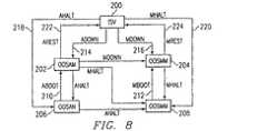
図8は、ノードに対するサービス状態の正当な移行を表す図である。全ての自動状態は他の自動状態に移行し、全ての手動状態は他の手動状態に移行することに留意されたい。手動状態から自動状態への正当な移行はない。このときISV状態は、自動または手動の指示を有しない。状態は、IN−SERVICE(ISV)状態200と他のいずれかの状態との間を移行することができる。図8で使用している頭字語は、以下のように復号される。
【0121】
【表1】
ノードシステム保全性サブシステム(クラス名NodeSI)は、単一のサーバノード内における故障隔離および監視サービスを提供する。全てのプロセス障害は、このサブシステムによって記録され、復旧動作のためにノード管理に転送される。ノードシステム保全性は、以下の特徴を与える。
【0122】
− 受動的プロセス監視(信号の受止め)
− ノード間通信の監視
− 局所故障報告
AINプラットフォームのシステム保全性(SI)能力は、プラットフォームのサーバノードにわたって能力を提供するものと、単一のサーバノード内で能力を提供するものとに分類することができる。NetSIは、プラットフォームレベルでシステム保全性能力を扱うが、NodeSIは、単一ノードレベルでシステム保全性を提供する。NodeSIは、プラットフォームのあらゆるサーバノードに常駐し、各構成可能エレメントに対するプロセスが、そのプロセスの故障ステータスを報告することができるための動作を提供する。これらの故障には、以下のものが含まれる。
【0123】
・各プロセス上で定期監視オブジェクトによって検出される故障
・ノード間通信障害
・ホストとサーバネットワークとの間の通信障害
・IMサーバプロセスによって検出される故障
NodeSIはまた、ノード間の全ての接続に対するノード定期監視も行う。通信故障が検出される場合、NodeSIは、その通信故障をNetSIに通知する。報告される故障により、NodeSIは、IPRの発行およびノード状態のダウングレードを含めた適切な動作をとる(NodePMと共同して)。
【0124】
NodeSIは、各サーバノード上のディスク利用を監視し、次いで、特定のファイルシステム上で使用される総容量があるしきい値を超えるとき、適切なIPRを発行する。NodeSIによる他のオブジェクトとの通信は、DOMEインタフェースを介して処理される。NodeSIは、構成内の全てのIPUのリストをNodePMから得る。各IPUからの以下の情報を含む配列が設定される。
【0125】
・NodePMから受け取ったIPU情報
・IPUステータス
・故障総数
・アライブメッセージ受領済みインジケータ
ステータスを他のNodeSIと通信するために、ノード名よりも、このリストへの配列インデックスが使用される。というのは、文字列の比較は、速度および効率性の面からみてコストがかさむ可能性があるからである。したがって、構成内の各ノードが、同じオーダの同じIPUリストを有することが重要である。
【0126】
NodeSIはNodePMに登録して、ノード状態の通知を受ける。NodeSIが他のIPUに対するステータス変化の通知を受けると、NodeSIは、IPU配列中のIPUステータスを更新することになる。ステータス変化が休止状態への変化である場合、NodeSIは、故障総数およびアライブメッセージ受領済みインジケータをクリアすることになる。
【0127】
NodeSIは、その定期監視機能を扱うために2つのタイマを有する。
【0128】
・BroadcastTimer(ブロードキャストタイマ)−NodeSIがその視野にある他のNodeSIに「I’m alive」メッセージをブロードキャストするようにするタイマ。
【0129】
・ConMonChkTimer−適切な「I’m alive」メッセージが全ての接続に対して時間間隔内に受け取られたかどうかを、NodeSIが判定するようにするタイマ。
【0130】
ノードがOS−MINであることをNodeSIが通知されると、NodeSIは、その視野にある他のNodeSIに「I’m alive」メッセージをブロードキャストし始める。次いでNodeSIは、ブロードキャストタイマをトリガする。ブロードキャストタイマが切れる際、NodeSIは、直ちに「I’m alive」メッセージを再びブロードキャストし、ブロードキャストタイマを再トリガする。これは、継続している場合のあるどんなNodeSI処理にも割り込むことになる。
【0131】
NodeSIが「I’m alive」メッセージを他のNodeSIから受け取ると、NodeSIは、適切なIPU配列エントリのアライブメッセージ受領済みインジケータにマークする。
【0132】
ノードがOS−MINであることの通知をNodeSIが受けると、NodeSIは、ConMonChkTimerをトリガする。ConMonChkTimerが切れる際、NodeSIは、CommFailCheck動作へのDome呼出しをして、通信障害の検査を行い、タイマを再トリガする。NodeSIは、アライブメッセージをブロードキャストする優先度が与えられるのを保証するために、それ自体にDOME呼出しを使用している。
【0133】
通信障害の処理は、その配列内の各IPUを検査して、最後の検査以後にアライブメッセージが受け取られたかどうかを判定することを伴う。受け取られていれば、アライブメッセージ受領済みインジケータがクリアされる。メッセージが受け取られておらず、IPUステータスが休止されていなければ、そのノードに対する故障総数がインクリメントされることになる。そのIPUに対する故障回数がその最大限に達していれば、NodeSIは、NetSIに通信障害を報告する。
【0134】
故障総数の最大数は、キーワード「MAX_COMM_FAULTS」の使用によって、コマンドラインから読み込むことのできる構成可能な値である。値が与えられない場合、故障総数のデフォルト数は2となる。また、コマンドライン中に与えられた値が2よりも小さい場合、最大数は2に設定される。
【0135】
アライブメッセージの各ブロードキャスト間の秒数は、キーワード「BRODCAST_ALIVE−SECS」の使用によってコマンドラインから読み込むことのできる構成可能な値である。値が与えられない場合、ブロードキャスト間の秒のデフォルト数は1秒となる。コマンドライン中に与えられた値が1秒よりも小さい場合、秒数は1に設定される。
【0136】
各定期監視検査の間の秒数は、キーワード「CONMON_CHK_SECS」の使用によってコマンドラインから読み込むことのできる構成可能な値である。値が与えられない場合、検査間の秒のデフォルト数は2秒となる。コマンドライン中に与えられた値が2秒よりも小さい場合、秒数は2に設定される。
【0137】
NodeSIは、あらゆるノードの起動の一部として、他のプロセスの起動前に、NodePMによって始動される。その初期設定の一部として、NodeSIは、NodeSIによって検出される故障の定義を含む記述子ファイル(Fault.des)を読み取り、これらの故障記録のリスト(FaultInfoList)を作成する。各故障記録(FaultInfo)は、以下の部分を含む。
【0138】
・FaultId−故障の識別
・FaultActId−報告される故障ごとに行われる動作
故障が受け取られるとき、NodeSIは、故障のIDを使用してそのリスト(FaultInfoList)中の故障記録を検索し、その故障に関連する動作を行うことになる。これらの動作は以下のことを含む場合がある。
【0139】
・適切なIPRを発行する。
【0140】
・NodePMプロセス上の破局的故障を検出した場合にノードを休止する。
【0141】
・構成可能エレメント上の自発的なステータス変化をNodePMに報告する。
【0142】
・通信障害をNodePMに、そしてまたNetSIに報告する。
【0143】
全ての故障(定期監視または他のプロセスから発するもの)は、NodeSIのNotifyFault動作を介して、各プロセスからNodeSIに報告されることになる。NodeSIは、サーバノード上のディスク利用を常に追跡し、80が使用された場合にIPRを発行する。
【0144】
NodePMインタフェース
NodeSIは、NodePMから提供されるインタフェースを使用して、構成可能エレメントのステータスの自発的な変化(AutoChgCEStat(...))を報告する。ノードの状態に対する構成可能エレメントの影響により、ステータス変化は、NodePMが以下の動作のいずれかを行うことを引き起こす場合がある。
【0145】
・ノードの状態をダウングレードする−この動作は、構成可能エレメントのステータス変化が、ノードの現在の動作状態に重大な影響を与えた場合に行われる。この動作を行う前に、NodePMは、その意向をNetSIに通知し、タイマを始動させる。次いで、NetPMからの要求時、またはタイムアウト時、NodePMはノードの状態をダウングレードする。
【0146】
・通信障害を報告する−この動作は、構成可能エレメントのステータス変化がノード間通信障害を示した場合(TCPリンクがサービス停止となる)に行われる。この場合、NodePMは通信障害をNetSIに通知し、通信を再び確立するよう試みる。
【0147】
NetSIインタフェース
NetSIは、以下の状態を報告するためにNodeSIおよび/またはNodePMによって使用される動作を提供する。
【0148】
・IPUのステータスにおける自発的変化(DowngradeIPStat(...))−この場合、NetSIが、NetPMを通してノードをダウングレードする(ノードがまだ休止されていなければNetPMにダウングレードを要求する)。
【0149】
・通信障害(CommFaultRprt(...))−この場合、同じIPUへの通信障害が他のIPUから報告されると、NetSIは、そのIPUを故障中IPUとしてマークし、NetPMを通してそれをダウングレードするよう試みる。
【0150】
定期監視インタフェース
各構成可能エレメントプロセスには、プロセス上で異なる信号を生成する異常な状態/イベントを検出して報告するために、定期監視オブジェクトのインスタンスを生成することが必要とされる。定期監視は、NodeSIのNotifyFault動作を介してこれらの状態を報告する。NodeSIに故障を通信するのに失敗した場合、定期監視は、そのインスタンス生成の時点で設定するオプションにより、ノードをHALTにすることができる。
【0151】
メッセージハンドラ/論理リンクインタフェース
メッセージハンドラまたは論理リンク構成可能エレメントプロセスは、NodeSIの動作NotifyFaultを利用して、DNI/TCPリンク上の故障を報告する。
【0152】
サービスマネージャ(SMProcess)
サービス管理サブシステムは、アプリケーションプロセスに対するプロセス制御を提供する。アプリケーションプロセスは、ノードがIN SERVICE稼動レベルを達成した後でしか稼動されない。アプリケーションプロセスは、サーバノード上で個別に除去/復元、およびイネーブル/ディスエーブルすることができる。ネットワーク管理は、どのアプリケーションを除去、復元、イネーブル、ディスエーブルするかを、サービス管理に通知する。サービス管理によって与えられる特徴は、以下を含む。
【0153】
− 能動的プロセス監視(ハートビート、監査)
− 複数プロセスのインスタンスサポート
− アプリケーションプロセスの状態管理
− 管理状態
− 動作状態
− 使用状態
− アプリケーションプロセスの状態変化の通知
一貫した構成可能エレメントインタフェースを提示する通信プラットフォームナビゲータの特徴のために、NodePMの代わりに、サービス管理がシステムの構成可能エレメントを始動させるように変更がなされている。こうすることにより、システム内の全てのプロセス(サービス管理を除く)は、サービス管理によって始動され、このとき各構成可能エレメントの特徴は、システム全体で同じである。通信プラットフォームナビゲータGUIを生み出すために、通信プラットフォームシステムの一貫した計画が存在しなければならない。図9Aは、ノード初期設定中に、通信プラットフォーム内のエンティティ間に存在する新たな関係を示す図である。構成可能エレメントが全てのサービス管理機能を利用できるようなるために、サービス管理インタフェースは、以下のことを必要とする。
【0154】
・全てのノード上で稼動する最初のものとして、ブートスクリプト230が生成される。ブートプログラム230が稼動するとき、このブートプログラムは、プラットフォームマネージャノード232を識別し、アクティブなプラットフォームマネージャノードのTcl記述子ファイル234を上書きコピーして、そのノードを立ち上げるのに使用する。ブートプログラムは、それが立ち上がる最初のプラットフォームマネージャノードであると決定する場合、既存のTcl記述子ファイル234を使用して稼動させる。
【0155】
・プラットフォームマネージャサブシステム、およびサービス管理サブシステム236は、前のバージョンのプラットフォームにおける構成可能エレメント238について異なる概念を有する。これら2つの概念は、これらの別々の機能が併合されて、1つの構成可能エレメントの概念にまとめられる。こうするために、プラットフォームマネージャサブシステムは、もはや構成可能エレメントの除去および復元をすることはなく、構成可能エレメントの除去および復元を希望するときに、サービス管理に通知することになる。このときサービス管理は、始動される最初の通信プラットフォームプログラムとなり、常にその初期設定の一部としてNodePMを始動させる。次いでNodePMは、前と同じように処理の開始および停止を制御するが、前のRemoveCEおよびRestoreCE機能を通してでなく、サービス管理を通してのみ、これを行う。
【0156】
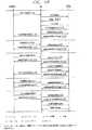
図9Bは、MIN_SET状態へのノード初期設定を示すメッセージ流れ図である。図9Cは、IN_SEVICE状態へのノード初期設定を示すメッセージ流れ図である。図9Dは、POST_ISV状態へのノード初期設定を示すメッセージ流れ図である。
【0157】
図10は、SMと構成可能エレメントとの間で使用されるメッセージプロトコルの概要を示す。サービス管理は、構成可能エレメントが、サービス管理インタフェース(SMI)オブジェクトにリンクできない場合でも、構成可能エレメントを始動させることができるが、サービス管理が備える特徴の多くは利用できなくなる。
【0158】
イベントマネージャ(eventmanagerimpl)
イベントマネージャサブシステムは、登録された1つまたは複数の相手に、包括的にイベント通知を発行することができる能力をユーザに提供する。システムには、複数のイベント(Managerオブジェクトインスタンス)が存在してもよい。ノードレベルのイベント(Manager)は、全てのノードに存在する。また、1つのプロセスに専用のイベントに登録するための能力を、それに関心のある相手に提供するために、その他のイベント(Managerインスタンス)が存在してもよい。eventmanagerimplプログラムは、それが稼動し続けているモードに対して、イベント(Managerオブジェクトインスタンス)を提供する。ノードに関連するイベントは、そのイベント(Managerインスタンス)を通して発行される。特定のノード上のイベントに関心のあるユーザは、そのノード名をイベント(Manager名)に使用して、そのノードイベント(Managerインスタンス)に結び付けることができる。プログラムもまた、その中にイベント(Managerオブジェクト)を埋め込むことができる。これを行うプログラムの一例は、IprMgrImplプログラムである。IprMgrImplは、IprEventMgrと名付けられたイベント(Manager)を有する。ユーザはIPRイベントの受取りを希望する。特定のイベントに関心のあるユーザは、特定のイベント(Managerインスタンス)に登録して、そのイベント(Managerインスタンス)を通してそのイベントを受け取ることもできる。イベント(Manager)は、登録された相手のリストを持続的に格納するわけではない。イベント(Managerが)、過ぎ去ったイベント(Receiver)にイベントを転送しようとしても、そのイベント(Receiver)はリストから除去されている。
【0159】
図11に、通信プラットフォームシステムにおけるイベント(Manager250)の2つの使用例を示す。eventmanagerimpl252は、ノードイベント(Managerオブジェクトインスタンス250)を含む。NodePMMain通信プラットフォームプログラム254は、このイベント(Manager250)を使用して、ノードが状態を変更したときにイベントを発行する。次いで、アプリケーションプログラム256は、イベント(Receiverオブジェクト268)を生み出し、CORBAオブジェクトリファレンスを「Node123」イベント(Manager250)上の登録呼出しに渡す。NodePMMain254が「Node123」イベント(Manager250)上の通知を呼び出すことによってイベントを生成すると、このイベント(Manager250)は、このイベントを受け取るために登録した全てのイベント(Receiverオブジェクト258)を検出することになる。イベント(Manager250)は、アプリケーションプログラムがこのイベントに登録していることを知ると、そのイベント(Receiverオブジェクト258)上の通知方法を呼び出し、イベント(Receiverオブジェクト258)は、通知方法がアプリケーションプログラム256中で呼び出されるようにすることになる。上記の例では、アプリケーションプログラム256はまた、IprMgrImplプログラム262中の「IprEventMgr」イベント(Manager260)にも登録している。NodePMMMain254がIprMgrImplインタフェースを使用してIPRを発行すると、IprMgrImplプログラム262は、そのIPR上を検索し、検証し、「IprEventMgr」イベント(Manager260)上の通知を呼び出す。これにより、そのイベント(Manager250)は、登録呼出し中で渡された、アプリケーションプログラム256中のイベント(Receiver264)に、生成されたイベントを転送する。
【0160】
アプリケーションプログラム256は、IprMgrImplプログラムがしたのと同じように、それ自体の名称を有するそれ自体のイベント(Manager)を生成することができる。イベント(Managerインスタンス)は、間違ったイベント(Manager)に対するイベントの生成を防止するため、またはユーザを間違ったイベント(Manager)への登録から隔離するのを補助するために、システムで固有の名称を有する必要がある。
【0161】
IPR/ALARMサービス
情報および問題報告(IPR)サブシステムは、情報および問題報告を発行する能力を、システムにおける全てのプロセスに提供する。IPRは、システムのユーザに、誤り状況または他の関係するシステム情報について通知するのに使用される標準的な機構である。情報および問題報告サブシステムは、通信システムにおけるIPRの収集を実施する。警報は、IPRに結合することのできる機構である。現在、警報サービスは利用できないが、将来公開される通信プラットフォームでは利用可能になるであろう。
【0162】
IPRサブシステムは、いくつかの特徴を備える。IPRサブシステムは、アクティブ/待機IPRサービス冗長性、登録された受信器にIPRを転送する能力、ホストにIPRを転送する能力、リアルタイムでIPRを表示する能力、レガシーPAConfigurableエレメントIPRインタフェースおよびCORBA IPRインタフェースとの後方互換性、IPRの検証にIPR辞書を使用する能力、IPR辞書から発行されたIPRに関する追加情報を提供する能力、およびIPR辞書中にIPRを提供する能力を備える。
【0163】
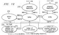
図12を参照すると、IprMgrImplプログラムは、通信プラットフォームサイトにおける全てのIPRに対する収集ポイントである。このプログラムは、IprMgrImpl CORBAサーバオブジェクトを含む。IprMgarImplオブジェクトは、アクティブ/待機の各プラットフォームマネージャノード上で稼動する。IprMgrImplが反応するアクティブ/待機状態は、通信プラットフォームマネージャノードのノードレベルのアクティブ/待機状態である。プラットフォームマネージャノードがアクティブ/待機状態を変更するとき、待機のIprMgrImplオブジェクトは、そのインタフェースを公表せず、アクティブなIprMgrImplオブジェクトは、そのCORBAインタフェースを公表することになる。こうすることにより、IprMgrとIPRClientとのインターフェースの両方のクライアントユーザは、自身のIPRをアクティブなIprMgrImplオブジェクトに転送することになる。
【0164】
イベントマネージャサブシステムは、IPRを配布するためにIPRサブシステム内で使用される。これにより、IPRを複数の宛先に転送することができる。イベントマネージャを使用することにより、インタフェースの変更をこうむることなく、追加のIPR特徴をシステムに容易に追加することができる。IPRサブシステムのイベントマネージャ機構は、現在、いくつかの既存のIPRサービスを提供するために通信プラットフォーム内で使用されている。リアルタイムIPR GUI270は、IPRが発生したときに、それらを表示する目的でIPRを受け取るために登録する。Ipr2hostプログラム272は、IPRを受け取ってそれらをホストに転送するために、IPRサブシステムに登録する。IPRを受け取ってディスクに記録するために、IPRロガーも登録することができる。
【0165】
ipr2hostプログラム272は、IPRをホストに転送することを担当する。このプログラムは、IprMgrImplのイベントマネージャからIPRを受け取り、引き続き転送するためにホストメッセージをフォーマットする。ホストに転送される全てのIPRは、メッセージハンドラサブシステムを使用して、IPR_ASSERT論理リンクを介してIPRを転送する。
【0166】
IPRサブシステムは、2つの外部インタフェースを有する。すなわち、IPRクライアントインタフェース274およびCORBA IPRインタフェース276である。IPRクライアントインタフェース276は、以前に公開されたPAConfigurableエレメントとの後方互換性のために存在する。IPRクライアントインタフェース274から発行されたIPRが、IPRクライアントコードによって変換されると、IPRは、IprMgrImpl CORBAインタフェースの使用によって発行され、アクティブなIprMgrImplオブジェクトに送られる。このインタフェースは、旧来のPAConfigurableエレメントIPRを、現在のIPRサブシステム形式に変換するための入力として、LOCIPRDB.DSK IPR辞書をまだ使用する。これには、IPRを発行するプログラムを有する各ノード上に、LOCIPRDB.DSKが常駐することが必要となる。LOCIPRDB.DSK辞書は、以前に公開されたものでは、IPRがホストに転送される前に、IPRの検証を行うのに使用されていた。IPRをLOCIPRDB.DSK辞書に入力するためには、RegisterIPRユーティリティが使用される。データベースエントリ中のフィールドは、ASCIIキー(IPRテキスト)、ホストIPR番号、IPR優先度、使用されるデータワード数、およびデータワード形式を含む。IPRMgrをテストするために、IPRは、ipr.inで定義されなければならず、これは、キーによる辞書に変換されることになる(RegisterIPRユーティリティを介して)。
【0167】
IprMgrImplインタフェースは、CORBA IDLインタフェースである。IPRがこのインタフェースを使用して発行されると、IPRは、LOCIPRDB.DSK辞書に入力される必要はない。IprMgrImplオブジェクトは、発行されたIPRを受け取ると、そのIPR辞書中でそれを検索し、発行するIPRイベントを構築する。IPRイベントは、IPRを発行したクライアントから渡された情報、およびIPR辞書からの情報を含む。IPRは、IPRの発行前に、IPR辞書およびMegaHubホストのIPR辞書に追加されなければならない。IPRを、IprMgrImpl IPR辞書に追加するためには、IprDriverツールが使用される。IprMgrImpl IPR辞書内に場所を占めるように、VAX IPRファイルをIprDriverで使用できる形式に変換するのを助けるために、再フォーマットおよび再フォーマット2スクリプトが存在する。
【0168】
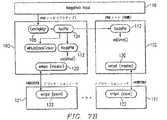
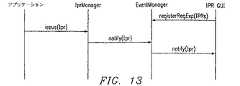
図13に、アプリケーションがIPRを発行し、IPRマネージャがそれを処理し、イベントマネージャがそのIPRを視覚表示用にIPR GUIに送る筋書きを示す。
【0169】
1)IPR GUIが、IPRイベントマネージャに報告される全てのIPRを受け取ることへのインタレストを登録する。
【0170】
2)アプリケーションがIPRを発行する。
【0171】
3)IPRマネージャがイベントマネージャにIPRを転送する。
【0172】
4)イベントマネージャがIPR GUIにIPRを配布する。
【0173】
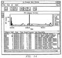
図14は、IPRビューGUIのスクリーン印刷の一例である。IPRビューGUIアプリケーションは、分割されたウィンドウにIPRの表示を提供する。上部の枠には、カテゴリベースで表示されたコスト対時間によるIPRの図表を示す。下部の枠は、IPRの従来の完全/簡略なテキストビューを表示する。サブカテゴリを見ることもでき、いくつかの表示カスタマイズが可能である。さらに、表示されるIPRに対する、フィルタリングおよび強調も可能である。通信はCORBAを介して処理される。
【0174】
統計サービス
データ収集(DcMProcess、DcProcess)
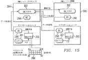
図15を参照すると、データ収集サブシステム(DC)298は、ノード内のアプリケーションプログラムにトラフィック測定機能を提供する。これらの測定は、ペグカウンタ(Pegcounter)クラスによって記録される総数、およびタイムメータ(TimeMeter)クラスによって記録される経過時間である。テストするペグカウンタ299は、共用記憶域300およびセマフォを間接的にテストすることになる。クライアントプロセス301は、共用記憶域300にペグし、データ収集298は、共用記憶域300から収集してDCマスタ302に送る。30分ごとに、データ収集298は、30分あたりのペグカウンタスロット299をDCマスタ302(アクティブなプラットフォームマネージャノード内の)に送り、次いでデータ収集は、これらのスロットをゼロにする。アクティブなプラットフォームマネージャノード304は、待機プラットフォームマネージャノード306を更新する。
【0175】
図16を参照すると、統計サービスまたはデータ収集サブシステム320は、プラットフォームのトラフィックの計量および測定能力を備える。このサブシステム320は、ペグカウンタ、タイムメータ、しきい値カウンタなどの統計測定の生成、収集、および報告と、収集および照会をサポートする。ペグカウンタ322およびタイムメータ324は、分散アプリケーションを介してサポートされるように示してある。データ収集サブシステム320によって与えられる特徴は、以下のものを含む。
【0176】
− ペグカウンタ322およびタイムメータ324APIサポート
− 複数のノードからの累積データの収集
− 統計をローカルで見るためのGUIへの報告
− 報告カスタマイズ用にユーザによって定義される測定セット
しきい値カウンタ(TCSServer)
しきい値カウンタサブシステムは、orbelineORBの実行を使用して、オブジェクト要求ブローカ(ORB)分散オブジェクトとして実行することができる。アプリケーションは、Orbelineを介してプラットフォームマネージャノードに常駐するサーバオブジェクトに接続される。サーバは、分散オブジェクトメッセージング環境(DOME)を介して、アプリケーションにカウンタしきい値交差を報告する。サーバオブジェクトは、しきい値カウンタサーバプロセス、TCServerによって生成される。各TCServerプロセスもまた、Orbelineを介して遠隔ノード上でTCServerと通信し、したがって、カウンタはサイトにわたって同期化できる。TCServerは、共通サービスライブラリ中に供給される永続性の辞書を、テンプレートクラスRepShmDictとして使用して、全てのカウンタを永続性の記憶域に保持する。
【0177】
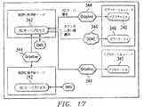
図17に、アプリケーションプロセス340とカウンタサーバプロセスとの間の通信パスを示す。TCServerプロセス342は、Orbeline344とDOME346の両方を介して、アプリケーションプロセス340と通信する。TCServerプロセス342は、orbeline impl_is_readyループ内で稼動し、アプリケーションプロセス340と別のノード上のTCServerプロセス342のいずれかからのサービス要求を待機する。このTCServerプロセスは、DOME ReqServ呼出しを行って、カウンタがそのしきい値に達したことをアプリケーションプロセス340に通知する。
【0178】
図18を参照すると、しきい値カウンタサブシステム360APIは、orbeline特有の実行部分をアプリケーションプログラマから隠している。その代わりに、サブシステムのクライアント側は、2つの層、すなわちORB独立層362およびorbeline依存層364で構成されることになる。サブシステムのorbeline特有の実行は、アプリケーションプログラマより隠されているが、サブシステムの分散性質はそうではない。カウンタのインクリメントに必要とされる時間を最小限にするために、カウンタのインクリメントは、API中でバッファされ、バッチでサーバに送られる。これは、アプリケーションが、APIオブジェクト上の何らかの動作の成功または故障の通知を即時に受け取ることができないことを意味する。
【0179】
通信サービス
メッセージ処理(MsgHndl、LinkXXX)
図19および20に示すように、メッセージ処理サブシステム370は、メッセージベースのプロセッサ間通信サービスを提供する。一般に、サーバノード上のプロセス間における全てのプロセス間通信は、図21に示す分散オブジェクトメッセージング環境(DOME)372を介して実行される。DOME372は、情報がノードの境界をわたって通信されなければならないとき、メッセージ処理サブシステム370を使用する。メッセージ処理サブシステム370はまた、SCPホストなど、サーバ以外の外部システムとの通信用に使用される。メッセージ処理サブシステム370は、以下の特徴を与える。
【0180】
− 複数プロトコル用の共通インタフェース
− TCP/IP 374
− UDP/IP 376
− DECNET 378
− 同一の宛先を有する複数リンク用の単一アクセス識別子(論理リンクグループ名)
− 冗長リンク管理(スケーラビリティを向上させる)
− リンク障害の復旧
− 非同期受信インタフェース
分散オブジェクトサービス
図21を参照すると、DOME372は、プロセス間クライアント/サーバ通信に使用されるクライアント/サーバインタフェースである。DOME372は、サーバプロセス382がクライアントプロセス384によって使用されるオブジェクトおよびメンバ機能を登録することを可能にする、サーバインタフェース382を含む。DOME372は、サーバ記述を記憶する共用記憶域データベース380と、他のノードからのサーバオブジェクト記述を維持するスタンドアロンのDOMEサービス(DOMEServices)プロセスとを含む。DOME372はまた、ノードのDOMEデータベース中にあるどの登録済みサーバオブジェクトへのアクセスも提供する、クライアントインタフェース384も含む。
【0181】
プロセス間通信サブシステムは、主にDOMEで構成される。DOMEは、サーバオブジェクトおよびその方法を登録する能力を、システム内の他のプロセスがそれらの方法を呼び出すことができるような形で、プロセスに提供する。DOMEは、故障回復ソフトウェアの開発を補助する、多くの特別なルーティングオプションを含む、様々な登録およびアクセスのモードをサポートする。プロセス間通信サブシステムによって与えられる特徴は、以下のものを含む。
【0182】
− ノードおよびサイトにわたる登録済みオブジェクト名の管理
− 優先順位のある要求の処理
− アクティブ/待機オブジェクト要求のルーティング
− 共用オブジェクトのロード(Load Shared Object)要求のルーティング
− オブジェクトのブロードキャスト(Broadcast Object)要求のルーティング
− ブロック化/非ブロック化オブジェクト要求
共通サービス
共通ユーティリティサブシステムは、プラットフォーム層上でまたはその内部で稼動するように構成されるプロセスの迅速な開発を補助する、プログラミングツールのライブラリを提供する。共通ユーティリティサブシステムによって与えられる特徴は、以下のものを含む。
【0183】
− コマンドラインオブジェクト
− トレースオブジェクト
− 共用記憶域オブジェクト
− セマファオブジェクト
− キーによる辞書オブジェクト
− リストオブジェクト
− 複製されたキーによる辞書オブジェクト
− 共用記憶域辞書オブジェクト
− その他
DbgTraceオブジェクト
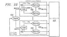
図22を参照すると、DbgTrace機能400は、トレースバッファ、ファイル、および/または標準誤差にトレースメッセージを発行する能力を備える。トレースデータは、異なる2つの形式、すなわち標準印刷形式およびデータバッファダンプ形式で入力することができる。マスク402は、異なるレベルのメッセージをフィルタリングするのに使用することができる。各DbgTraceグループに対して32の可能なマスクレベルが存在する。
【0184】
DbgCntlインタフェース404は、DbgTraceオブジェクト400に対する制御インタフェースである。これは、ユーザが、DbgTrace機能400の多くの異なる側面を指定することを可能にする。このインタフェースはまた、ユーザがDbgTraceオブジェクト400上で以下のことを行うのを可能にする。
【0185】
− DbgTraceグループ400に対するマスク402を設定/入手する。
【0186】
− 内部メッセージバッファ410のサイズを設定/入手する。
【0187】
− 存在するグループのリストを入手する。
【0188】
− 標準誤差への表示をオン/オフに切り替える。
【0189】
− ファイルにトレースを1つづつダンピングするのをオン/オフに切り替える。
【0190】
− トレースを上書きされる前にファイルからトレースをダンプする能力をイネーブル/ディスエーブルにする。
【0191】
DbgDiskインタフェースは、全ての書込み要求上でどのファイルにトレースバッファ410が書き込まれることになるかを、ユーザが指定できるようにする。
【0192】
DbgTrace機能400は、それぞれが複数のグループのうちの1つに属することのできる、異なるDbgTraceオブジェクト400をユーザが生成することを可能にする。これにより、ユーザは、グループごとに固有のマスク値を有することができる。DbgTraceインタフェース400を通して発行される全てのトレースは、内部メッセージバッファに記憶される。ユーザはまた、内部バッファに加えて標準誤差にもトレースを発行するかどうかも指定できる。
【0193】
トレースオブジェクト
トレースオブジェクトは、標準誤差にトレースメッセージを任意に発行する能力をユーザに提供する。ユーザがトレースを発行するとき、このトレースが出力されることになるトレースレベルを表すマスクが指定される。トレースインタフェースは、そのUNIXプロセス中のトレースの全てのインスタンスが、トレースメッセージを発行するか否かを決定するのに使用することになるマスクを、ユーザが指定できるようにする。トレースマスクは、8つの固有のマスク値をサポートすることができる。
【0194】
辞書管理システム
図23を参照すると、辞書管理は、データの記憶およびアクセスをサポートするように構成されたクラスを提供する。辞書は、ディスク(永続的)またはメモリに記憶することができる。辞書はまた、私用(ローカルプロセスのみによって使用される)、または共用(複数のプロセスからアクセスできる)とすることもできる。これらの辞書の目的は、アプリケーションプログラムによって定義される。DmsMaster430とDmsServer432との間の主要な相互作用は、DmsMaster430が、アプリケーションから更新メッセージを受け取ったときに、DmsServer432を更新することである。DmsMaster430は、プラットフォームマネージャノード内でアクティブ/待機で稼動し、DmsServer432は、全て(または1つのサブセット)のIPU内で稼動する。
【0195】
イベントサービス
イベントサービスは、タスクにとって重要な特定の出来事を、ゆるく結合されたプロセス間で生成および配布する能力を備える。イベントの一例は、入出力転送の完了である。イベントサービスは、CORBAベースのプロセス間通信機能とすることができる。これは、オブジェクトによって動作が実行されることになる、標準的なCORBA要求を使用する。これは、イベントマネージャ実行プログラムを通して達成される。
【0196】
オブジェクトに対して異なる2つの役割を定義することにより、通信はオブジェクト間で分断され、非同期通信が生成される。1つのオブジェクトは、新しいイベントを受け取って蓄積し、もう一方のオブジェクトは、これらの新しいイベントに転送される関心を登録する。これは、2つのCORBAクラス、すなわちイベントマネージャおよびイベントレシーバによって達成される。イベントマネージャは、新しいイベントを受け取るためのインタフェース定義言語(IDL)インタフェースを提供する。イベントレシーバは、イベントを受け取ることに関心のあるクライアントのためのインタフェース定義言語インタフェースを提供する。
【0197】
ソフトウェアおよびハードウェア表現
図24に、通信プラットフォームシステムのハードウェア図を示す。最上レベルでは、通信プラットフォームシステムは、1つまたは複数のサイト440を含む。サイト440内には、複数のノード442が存在する。
【0198】
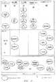
ソフトウェア表現は、ソフトウェアの構成要素を共にグループ化することのできる階層構造である。図25に、この階層構造を示す。最上レベルには、アプリケーション450が存在する。アプリケーション450は、1つまたは複数の構成可能エレメントセット452からなり、構成可能エレメントセットは、1つまたは複数の構成可能エレメント454からなる。複数のアプリケーション450を、システム内で定義することができる。システム内の全てのアプリケーション450は、システムのソフトウェア表現を構成する。
【0199】
ソフトウェアの、システムのハードウェア表現への動的マッピングを図26に示すが、これは、どのようにアプリケーション450の各部分が、ノード442上に配置されるかを示している。サイト440はアプリケーション450を含む。アプリケーション450は、プロセッササービスグループ456を有する。プロセッササービスグループ456は、複数のノード442にまたがる。ノード442上には、構成可能エレメントセット452が配置される。構成可能エレメントセット452内には、構成可能エレメント454が常駐する。例えば、時間依存ルーティングアプリケーションのソフトウェア表現が、2つの構成可能エレメントセット、すなわち西海岸セット(WestCoastSet)および東海岸セット(EastCoastSet)を有するとする。西海岸セット内では、時間依存ルーティングアプリケーションは、西海岸の呼出しを処理するように的を絞られたノード上で稼動する必要のある全てのプログラムを有することができる。これらのプログラムには、西海岸での処理用に特に構成されたデータベースプログラム、リンクプロセスなどを含めることができる。東海岸セット内では、時間依存ルーティングアプリケーションは、東海岸の呼出しを処理するように的を絞られたノード上で稼動する必要のある全てのプログラムを有することができる。次いで、時間依存ルーティングアプリケーションがサイトに割り当てられる。時間依存ルーティングアプリケーションを稼動させることになるノードは、プロセッササービスグループ内にグループ化される。次いで、アプリケーション用の構成可能エレメントセットは、時間依存ルーティングアプリケーションのプロセッササービスグループ内に配置されたノード上に配置される。
【0200】
本発明のいくつかの実施形態およびその利点を詳細に述べたが、本発明の教示、添付の特許請求の範囲に述べる本発明の趣旨および範囲を逸脱することなく、変異、変更、代用、変換、修正、変形、および代替が、それに対して可能であることを理解されたい。
【図面の簡単な説明】
【図1】 本発明の一実施形態による通信プラットフォームアーキテクチャ層の概略ブロック図である。
【図2】 本発明の一実施形態による通信プラットフォーム概念構成要素の概略ブロック図である。
【図3】 本発明の一実施形態による通信プラットフォームの概念構成要素、およびそれらの間の関係のブロック図である。
【図4】 本発明の一実施形態による通信プラットフォームの論理区画分けの概略ブロック図である。
【図5】 本発明の一実施形態による通信プラットフォームサービス、およびその依存関係の概略ブロック図である。
【図6】 本発明の一実施形態による通信プラットフォームの物理的区画分けの概略ブロック図である。
【図7A】 本発明の一実施形態によるNetPMのテストフローのブロック図である。
【図7B】 本発明の一実施形態によるNetPMの時間同期フローのブロック図である。
【図7C】 本発明の一実施形態によるネットワーク管理サービスとノード管理サービスとの間の障害検出および相互作用を示すブロック図である。
【図7D】 本発明の一実施形態によるコアサービス間の相互作用を示すブロック図である。
【図8】 本発明の一実施形態による通信プラットフォームノードの状態移行図である。
【図9A】 本発明の一実施形態によるノードスタートアッププロセスの概略ブロック図である。
【図9B】 本発明の一実施形態によるノード初期設定プロセスのメッセージ流れ図である。
【図9C】 本発明の一実施形態によるノード初期設定プロセスのメッセージ流れ図である。
【図9D】 本発明の一実施形態によるノード初期設定プロセスのメッセージ流れ図である。
【図10】 本発明の一実施形態によるサービス管理インタフェースプロトコルのメッセージ流れ図である。
【図11】 本発明の一実施形態によるイベントマネージャ使用を示す概略ブロック図である。
【図12】 本発明の一実施形態による情報および問題報告(IPR)の概略流れ図である。
【図13】 本発明の一実施形態によるIPR処理の概略流れ図である。
【図14】 本発明の一実施形態による例示的IPR閲覧グラフィカルユーザインタフェースである。
【図15】 本発明の一実施形態によるデータ収集を示す概略ブロック図である。
【図16】 本発明の一実施形態によるデータ収集サブシステムの概略ブロック図である。
【図17】 本発明の一実施形態によるしきい値カウンタデータ通信パスの概略ブロック図である。
【図18】 本発明の一実施形態によるしきい値カウンタサブシステムの概略ブロック図である。
【図19】 本発明の一実施形態によるメッセージ取扱いサブシステムの概略ブロック図である。
【図20】 本発明の一実施形態によるメッセージ取扱いテストの概略ブロック図である。
【図21】 本発明の一実施形態による分散オブジェクトメッセージ環境の概略ブロック図である。
【図22】 本発明の一実施形態による内部デバッグおよび追跡オブジェクト関係の概略ブロック図である。
【図23】 本発明の一実施形態による辞書管理システムの概略ブロック図である。
【図24】 本発明の一実施形態による通信プラットフォームのハードウェア表現の概略ブロック図である。
【図25】 本発明の一実施形態による通信プラットフォームのソフトウェア表現の概略ブロック図である。
【図26】 本発明の一実施形態による通信プラットフォームのハードウェア上へのソフトウェアの動的マッピング表現を示す概略ブロック図である。[0001]
TECHNICAL FIELD OF THE INVENTION
The present invention relates generally to the field of communications. More particularly, the present invention relates to communication platform systems and methods.
[0002]
Summary of the Invention
In one aspect of the present invention, a communication platform forms an interface between an application program that implements a communication function and an operating system that operates on at least one node in a site that supports the application program; Forms an interface between the program and the communication network. This communication platform provides a network management process operable to provide inter-node configuration, monitoring and management functions, and node management operable to provide initial node configuration, configuration, monitoring and management functions. Operable to provide a library of multiple programming tools for developing processes and application programs, and event processes operable to provide task initialization, termination, and distribution in response to a given event A common process, a communication process operable to provide a message handling function, and a distributed object process operable to provide a distributed database repository for object-based communication.
[0003]
In another aspect of the present invention, a software interface is provided between an application program that implements a communication function and an operating system that operates on at least one node in a site that supports the application program; A method is provided for forming an interface with a communication network. The method is operable to provide a network management process operable to provide inter-node configuration, monitoring and management functions, and to provide node initialization, configuration, monitoring and management functions. Providing a node management process, providing an event process operable to provide task initialization, termination, and distribution in response to a given event; a plurality of programming tools for application program development Operable to provide a common process operable to provide a library, provide a communication process operable to provide message handling functionality, and provide a distributed database repository for object-based communication Providing a distributed object process.
[0004]
In another aspect of the present invention, a software interface is provided between an application program that implements a communication function and an operating system that operates on at least one node in a site that supports the application program, and further communicates with the application program. A method is provided for forming an interface to a network. This method provides a network platform manager operable to remove a node from a service, restore a node to the service, remove an application from the service, and restore an application to the service, monitor the node, Providing a network system integrity manager operable to allow the failed node to recover, providing a configuration manager operable to interface with a host coupled to the communication platform, Providing a node platform manager operable to provide management functions, providing a service manager operable to start and stop processes at the direction of the node platform manager, and inter-node links The includes providing an operable node system integrity manager to monitor.
[0005]
For a better understanding of the present invention, reference may be made to the accompanying drawings.
[0006]
Detailed Description of the Invention
Architecture overview
The communication platform (TP) 10 of the present invention is a software system configured to support the development and execution of a distributed, scalable, disaster
[0007]
As shown in FIG. 1, the
[0008]
FIG. 2 is a block diagram of conceptual components related to the
[0009]
The configurable attributes of the configurable element include RunLevel (execution level), which is the level at which the configurable element starts. RunLevel includes PRE_MIN, OS_MIN, IN_SVC, and POST_IN_SVC. The PRE_MIN execution level specifies that a configurable element is automatically created by the service management subsystem at boot time. The PRE_MIN configurable element is not monitored by the platform manager subsystem. OS_MIN specifies that a configurable element is created when a node is transitioning to OS_MIN. IN_SVC specifies that a configurable element is created when a node is transitioning to IN_SVC. POST_IN_SVC specifies that a configurable element is created when the node transitions to the IN_SVC state. Another configurable attribute is NumberOfInstances (number of instances) that specifies how many times a copy of the executable function is executed. InServiceThreshold (in-service threshold) is a configurable attribute that specifies how many times it needs to be executed in addition to NumberOfInstances in order to set the state of the configurable element to ENABLED (enabled). If the number of instances falls below this threshold, the entire configurable element or all instances of the configurable element are removed. Another attribute of the configurable element is a HeartbeatSchedule that specifies a schedule for heartbeat messages sent to the configurable element. Each configurable element also has an AuditSchedule that specifies a schedule for audit messages sent to the configurable element.
[0010]
A configurable element set (CESet) 26 is defined as a group of configurable elements that are configured to be placed together on one or
[0011]
[0012]
[0013]
[0014]
[0015]
A processor service group (PSG) 22 is defined as a group of nodes where a specific configurable element set 26 is placed for redundancy. The
[0016]
FIG. 3 is a diagram illustrating a system 40 configuration that uses the conceptual components of the
[0017]
From a hardware configuration point of view, a node is a computer processor inside a network (such as Ethernet) that can act as a client or server. Each node has a single instance of an operating system running on the node. Since the processors inside the node depend on the operating system, they cannot operate independently of each other. Each node at the site can be classified as a platform manager or an application node. A site may consist of a node or a group of nodes connected to a host. The platform manager node has a redundant mate. The platform manager and its mate can operate in active / standby mode or load sharing mode.
[0018]
The system 40 has eight nodes and includes two platform manager nodes (active 42 and standby 43) and six application nodes 44-49. Based on the time the call was placed, or time-dependent routing, an
[0019]
The communication platform internal architecture was described in terms of logical and physical partitioning. Logical partitioning divides the communication platform into different functional areas, as shown in FIG. Each functional area includes a connectivity group of classes that combine to provide one specific system function. Physical partitioning describes the specific software and hardware decomposition of the system context. Services provided by the
[0020]
The core services 62 may include services that implement
[0021]
At a minimum, the communication platform provides all core services. High level applications use these services to perform lower level functions.
[0022]
FIG. 5 shows communication platform services and their dependencies. The developer accesses all core services and application services via the communication platform
[0023]
FIG. 6 is a diagram of the physical partitioning of the
[0024]
Hereinafter, the communication platform service will be described in more detail.
[0025]
Network management service
[0026]
Network Platform Manager (NetPMMain)
The class name for the network platform manager is NetPM. NetPM serves to provide a platform resource management function. The platform is a distributed system consisting of multiple nodes or servers that provide processing capabilities for specific services such as telephone card and credit card verification. Services provided by the server are determined by configurable elements that reside on the node. NetPM manages all configuration data related to the platform. The configuration data includes information regarding hardware such as the TCP / IP address of the server, status information such as server and inquiry status, software configuration information such as application type, node name, and information regarding individual component elements.
[0027]
NetPM maintains the following configuration information. These information are collected by NetPM during initial setup.
[0028]
Configurable element descriptor information
Provides configuration information about each configurable element of the platform. NetPM retrieves these from disk files that contain information about various types of configurable elements.
[0029]
・ Application information
It provides configuration information about each application (service) and can be used to calculate the status of the application. NetPM retrieves this information from a disk file that contains information about all applications in the platform.
[0030]
-Processor service group information
Configuration information about the processor service group can be provided and used in calculating the processor service group status (the processor service group represents a group of processors that provide the same application, ie, CCD, CCL). NetPM retrieves these from disk files that contain information about all processor service groups in the platform.
[0031]
・ Server information
Provides specific information about all servers in the platform. NetPM requests this information from ConfigMgr and retrieves it from there. ConfigMgr first provides server information about the platform manager node to NetPM. If ConfigMgr then determines that the current server is the active platform manager, it provides information about the remaining servers in the platform to the local NetPM. Otherwise (standby platform manager), NetPM retrieves the information from the mate, not from ConfigMgr.
[0032]
If an error is detected while collecting these information, NetPM issues an appropriate IPR and exits.
[0033]
NetPM uses NetMAP objects to manage all configuration data. NetPM also uses a persistent dictionary to maintain server status, query status, and scheduled action information across platform manager resets. A disk file dictionary object is used to manage this dictionary. NetPM is responsible for maintaining the integrity of the configuration data between the two platform manager servers. NetPM uses persistent dictionaries, database equalization, and auditing to maintain data integrity.
[0034]
The application status is determined based on the processor service group status. The following criteria are used to determine the processor service group status:
[0035]
・ PSG_DISABLED
At least a set number of servers in the processor service group are disabled.
[0036]
・ PSG_INACTIVE
At least one server in each processor service group is in a standby state and none is in an active state.
[0037]
・ PSG_ACTIVE_MINIMAL
Only some servers in the processor service group are in the active state.
[0038]
・ PSG_ACTIVE
A set number of servers in the processor service group are in an active state (Note: this number will be greater than the number of servers that must be active in PSG_ACTIVE_MINIMAL).
[0039]
Application status can be derived using the following criteria:
[0040]
・ AP_DISABLED
For a given application, at least a set number of processor service groups have a status of PSG_DISABLED.
[0041]
・ AP_INACTIVE
For a given application, at least one processor service group has a status of PSG_INACTIVE, and no processor service group has a status of PSG_ACTIVE.
[0042]
・ AP_ACTIVE_MINIMAL
For a given application, a set number of processor service groups have a status of PSG_ACTIVE_MINIMAL or higher (PSG_ACTIVE).
[0043]
・ AP_ACTIVE_PARIAL
For a given application, a set number of processor service groups have a status of PSG_ACTIVE_MINIMAL or higher (PSG_ACTIVE). Larger than the number).
[0044]
・ AP_ACTIVE
For a given application, a set number of processor service groups have a status of PSG_ACTIVE (note: the number of processor service groups required for AP_ACTIVE state is greater than the required number of processor service groups in AP_ACTIVE_PARIAL).
[0045]
NetPM keeps track of the status changes for each server node and, when they get them, determines the status of the processor service group, and if there is a change, determines the new application status for the node and passes this change to ConfigMgr. Inform.
[0046]
NetPM provides solicited updates and autonomous updates regarding application status. In autonomous update, an application program first registers a function with NetPM and receives an update for a specific application type (CCD or CCL). When NetPM receives a server or query status change from NodePM, the application status is calculated and the registered function is invoked with the old and new application status. The application status can be solicited, during which time NetPM returns the latest calculated application status stored in NetMAP to the requesting process.
[0047]
NetPM provides two sets of routing options for other processes that wish to communicate with NetPM, especially through the use of two alias objects. NetPM provides local and global active wait options. With the local option, all NetPM client requests are sent to the NetPM server object at the same node as the client object. With the global active wait option, all NetPM client requests are sent globally (ie, possibly between nodes) to an active NetPM server object.
[0048]
NetPM provides a set of read and write functions for multiple server configuration data. These include read / write functions for schedule action data, platform manager active status data, server status data, and the like. NetPM does not provide direct read / write operations on configurable element description data.
[0049]
NetPM also provides functions for initializing most server configuration data. This function expects a ServerInfoMsg object as input.
[0050]
NetPM provides a set of functions that allow specific configuration actions (graceful abort, immediate abort, graceful downgrade, and restore) to take place on a particular server.
[0051]
NetPM provides a function that can change the server status for a specific server.
[0052]
NetPM provides functionality to enable and disable query processing on a particular server.
[0053]
NetPM provides multiple functions to “report” server status and query status changes. These routines store the new status information in NetMAP, notify the ConfigMgr software of the change, and broadcast the change to all NodePM software in the platform.
[0054]
NetPM also plays a role of time synchronization inside the server network. Time synchronization consists of three main parts, as shown in FIG. 7B. The first part is where the
[0055]
Finally,
[0056]
[0057]
Network system maintenance (NetSIMaine)
A network system integrity (NetSI)
[0058]
− Platform Manager active / standby status monitoring
-Node failure report correlation
-Failed node recovery action
The class name for network system maintenance is NetSI.
[0059]
NetSI includes a communication failure list. This list holds the report server node name and problem server node name for each received communication failure report. When a communication failure report is received, the list is searched for other reports regarding the problem node. If not found, fault information is added to the list. NetSI also includes a down status information list. When the NodePM indicates that the node is out of service and the NetPM status does not indicate that the node is dormant, a down status information entry is created with the node name of the dormant IPU. A timer is created and down status information is added to the list. Later, if the NodePM shows a higher status for that node (before the timer expires), the down status information entry is cleared from the list and no further action is taken.
[0060]
NetSI periodically audits the status status of both PMs. If an invalid state exists, NetSI attempts to correct the status by setting the active status to the correct state. Other processes can also request NetSI to audit the platform manager status state.
[0061]
NetSI operates under the “send to both” load sharing concept. If the platform manager nodes are both active, each NetSI process at each platform manager node receives a NodeSI request. Each NetSI process determines whether to handle the request based on the active / standby state of the platform and the failed server. The active platform manager's NetSI process typically performs the required action, while the standby platform manager discards the information. However, if the failed node is the active platform manager, the standby platform manager sets itself active (if enabled) and takes the requested action to downgrade the other platform manager nodes.
[0062]
Each time a NetSI operation is invoked, NetSI first determines whether it is an active platform manager or a standby platform manager. If active, NetSI processes requests for all states except when the target node is itself and the mate is in service. In the standby state, NetSI discards requests for all states except when the target node is a mate.
[0063]
During initialization, NetSI requests the node name of the mate from the NodePM and the server identifier of its own server and mate server. Before requesting information, NetSI polls for the status of the NodePM and does not request a node name and server identifier until the NodePM is read and provided. NetSI will not be prepared to provide service until this information is properly received.
[0064]
NetSI gets the name of the network configuration (downgrade) report file name using the command line parameter DWN_RPT_FILE. If this parameter is not specified, no report entries are created from the downgrade.
[0065]
Referring to FIGS. 7C and 7D, the process interaction of node management and network management is shown. The periodic monitoring monitor (ConMon) is an instance of an object that operates on the
[0066]
In particular, each NetSI determines whether to handle a downgrade request. When handling a request, the status of the target server is retrieved. If the target server has not been paused, the server is downgraded to an appropriate status based on the IPU status. If the IPU status is out of service, NetSI invokes NetPM's immediate pause operation to automatically or manually pause the target node. If the IPU status is out-of-service minimum (OS-MIN), NetSI invokes NetPM's immediate downgrade operation to downgrade the target node to OS-MIN. If IPU status is disabled during service, NetSI invokes NetPM's disable query operation to disable query status for the target node. In any case, if the target node is an active platform manager, NetsSI updates the active status. Also, if the target node is part of the local site, NetSI informs the host that the status change has occurred via ConfigMgr and determines that the processor service group of the target server should be restored. Start recovery of the processor service group (via ConfigMgr). NetSI then writes an entry to the network configuration report file to indicate that a status change has occurred because the node reported a failure.
[0067]
NodeSI informs NetSI of a communication failure that has occurred between two nodes. NetSI stores the failure or takes action on the failure based on previous information reception (if any). Each NetSI determines the status of the reporting node and the problem node. If any server is dormant, the integrity of the data cannot be guaranteed and the communication failure report is discarded. If neither server is dormant, the communication failure list is searched for other reports on the problem node. If no report for the problem node is found, a communication failure list entry is added to the list along with server information. If another report for the problem node is found and the other report server has reported it, the problem server is set up to perform the downgrade process. Once a decision is made as to whether to downgrade the server, NetSI determines whether to handle it (based on the active state and whether the target server is itself). If the downgrade is to be handled, NetSI invokes NetPM's immediate pause operation to automatically or manually pause the problem node. If the server to be quiesced is an active PM, the active status is updated accordingly before quiescing the node. Also, if the target is part of a local site, NetSI informs the host that a status change has occurred via ConfigMgr and determines that the target server's processor service group should be recovered , Start recovery of the processor service group (via ConfigMgr). NetSI also writes an entry in the network configuration report file to indicate that it has been suspended due to a communication failure.
[0068]
Configuration Manager (ConfigMgr)
The configuration management subsystem (class name: ConfigMgr) provides a control interface between the SCP host and server components. All operations that can be performed on the server network are defined in this interface. The configuration management subsystem provides the following features.
[0069]
-Control message interface between host and server
-State machine for effective operation;
− Drive network management by demand
− Control the timing / timeout of the operation
ConfigMgr manages server configuration control for the platform manager. ConfigMgr receives host messages sent on the CONFIGCTL, MAINT, APLCTL, and ROUTINGCTL logical links and processes each based on its message id and type. If the host requests to send a response or report, ConfigMgr determines the required response, retrieves the required report information, and sends it back to the host. ConfigMgr handles the following messages:
[0070]
・ APPL_STATUS_MSG
・ ASPEC_MSG
・ CONFIGURE_SERVER_MSG
・ PSG_INFO_MSG
・ PSG_STATUS_MSG
・ QUERY_PROCESSING_MSG
・ RESET_SERVER_MSG
・ ROUTING_INFO_MSG
・ SCHED_ACTION_CTL_MSG
・ SERVER_INFO_MSG
・ SERVER_STATUS_MSG
・ TEST_SERVER_MSG
・ TIME_MSG
ConfigMgr also provides operations to the platform manager to retrieve server and time information from the host. ConfigMgr also provides the operation of notifying the host of server status changes. During processing of a host command message, ConfigMgr may have to wait for a response from the host or a state change from a particular server. ConfigMgr uses a non-blocking principle for these waits. ConfigMgr does not stop and wait for the event to occur, but saves the desired response or status on the Pending Queue and continues with normal, another host message processing, or to the client Provide service. If the desired response or status occurs, the appropriate procedure is called to resume processing of the host command message. If the desired response does not arrive within the specified time limit or the desired status does not occur, the failure procedure is called to clean up the processing of the host command message and issue an IPR as necessary.
[0071]
In addition to processing the host command message, ConfigMgr is also required to notify the host when a status change occurs. When ConfigMgr is notified of a status change, it checks the status pending queue to determine if it is waiting for a status change to occur. If waiting, a pending queue success operation is performed. Otherwise, ConfigMgr sends a server status message to the host. During processing of the host response message, ConfigMgr examines the host response pending queue (HostPendQueue) to determine if it is waiting for a response. If waiting, a pending queue success operation is performed. Otherwise, ConfigMgr discards the response message from the host. When the platform manager node is booted to the OS-MIN state, it audits its mate and determines its status. If there is no mate's platform manager node, the mate's status is automatically set to dormant. Similar audits are also performed on service server nodes (nodes other than PM) to determine their status.
[0072]
ConfigMgr has a registration function that allows a subsystem to register and provide routing information for a specific application. When the host requests routing information about the application, ConfigMgr requests the appropriate registered subsystem (if any) to provide routing information.
[0073]
The configuration server message (ConfigServerMsgs) requires special handling due to the nature of the service being performed (ie dormant, downgrade, restore, boot). Since host messages are sent to both platform manager services, care must be taken to ensure that only one platform manager node handles the request. This requires checking the server status of the platform manager node and its mate. Different actions are taken based on the server status of the platform manager node and whether the ConfigServer request is for the platform manager node, its mate, or the service server. Two finite state machines (PMCfgSvrFSM and SvcCfgSvrFSM) manage all operations driven by different states.
[0074]
PMCfgSvrFSM is a finite state machine that handles restore, quiesce, resynchronization, downgrade and boot to the platform manager application server. This machine is based on whether the request is for itself or its mate, its own status, its status, and the requested event (pause, downgrade, restore, etc.) Process the request. The platform manager server states to be checked are Halted (automatic), Halted (manual), XOS-MIN, AOS-MIN (automatic), MOS-MIN (manual), and In-Svc. For In-Svc, the active / standby status is examined to determine whether the server is active or standby. Valid events include Restoration, Graceful Halt, Immediate Halt, Immediate Halt, Graceful Downgrade, Immediate Downgrade, Graceful Boot, Immediate boot (Immediate Boot), host resynchronization (Host Resync).
[0075]
The event is important to determine which platform manager node will handle the request. When a restore is requested, usually the platform manager node that is to be restored handles the restore (ie, the platform manager node restores itself). When processing a dormant platform manager server restore request, the dormant server mate (if possible) sends a denial response back to the host. When a dormant, downgrade, or boot is requested from a platform manager node, the mate of the platform manager node handles it unless it is dormant. When a mate is dormant, the platform manager node handles its dormancy, downgrade, or boot on its own. The hibernation, downgrade, or boot process may involve actually performing the requested action or sending a rejection response back to the host. If a dormant, downgrade, or boot request is not rejected, the host considers the operation successful.
[0076]
When the platform manager node has to handle the boot on its own, the platform manager node calls NetPM's GraceHalt or ImmedHalt action (based on the boot type) to put itself in a dormant state. The process for this node is then complete because it has been lowered to a dormant state. (The host will initiate a reset and boot of its server.) When a dormant, downgrade, or boot is requested from the last In-Service platform manager node, the force flag is checked. If the force flag is not set, the request is rejected with a “DENIED-LAST AMP” response. If the force flag is set, dormancy, downgrade, or boot is performed on the last In-Service platform manager node.
[0077]
When a Host Resync is requested for a platform manager node, the target platform manager server mate will process the request unless it is dormant. If the target platform manager server mate is dormant, the platform manager node for resynchronization processes the request. Processing this request involves changing the server status from XOS-MIN to AOS-MIN or MOS-MIN, or rejecting the request if the current status is not XOS-MIN.
[0078]
SvcCFgSvrFSM is a finite state machine that handles restoration, dormancy, resynchronization, downgrade, and boot for service application servers. The machine processes requests based on the state of the platform manager node performing the operation, the state of the affected service server, and the requested event (pause, downgrade, restore, etc.). The service states to be checked are Halted (automatic), Halted (manual), XOS-MIN, AOS-MIN (automatic), MOS-MIN (manual), and InSvc. Valid events are restore, graceful quiesce, immediate quiesce, graceful downgrade, immediate downgrade, graceful boot, immediate boot, host resynchronization.
[0079]
The active platform manager node (OS-MIN or In-Service) handles configuration server requests to the service server. Restore, dormancy, resynchronization, or downgrade is allowed on the service server as long as one platform manager is at least in OS-MIN. Restoration to the service server is allowed only when at least one platform manager is In-Service. If no platform manager node is In-Service, the active platform manager node sends a DENY-AMP not In-Service response back to the host. If a dormant, downgrade, or boot request is not rejected, the host considers the operation successful.
[0080]
When a dormant, downgrade, or boot is requested for the last In-Service node of the application, the force flag is checked. If the force flag is not set, the request is rejected with a response of “DENIED-LAST SERVER IN Processor service group PROCESSING QUERIES”. If the force flag is set, dormant, downgrade, or boot is performed on the last In-Service node of the application.
[0081]
Whenever a configuration event (except for an immediate pause) is processed, the Under Configuration flag is checked. If the configuration flag is set, the request is rejected with a response of “DENIED-SERVER UNDER CONFIGURATION”. ConfigMrg sets and clears the configuring flag during event processing. Other messages (ie, ServerinfoMsg, ServerStatusMsg, TimeMsg, etc.) do not require a finite state machine.
[0082]
When the restore request is not rejected, ConfigMgr sets the UnderConfig flag for the server, sends the ConfigServerMsg “Action initiated” RESPONSE to the host, and restores the server to In-Service to restore the server to In-Service. Call. Then, ConfigMgr postpones the restoration process and sets a server status pending queue (Server Status Pending Queue) entry so that the server becomes In-Service. The restoration process is not continued until ConfigMgr is notified that the server status is In-Service or that the timer has expired. When ConfigMgr is notified of the server status change to In-Service, the restoration process is continued by checking the server query status. If the server's query status is DISABLED_SERVER_OOS and the number of active servers is less than the total number of active servers in the processor service group, ConfigMgr invokes NetPM's EnableQuery operation to enable the server's query status and the current query Set the status to Pending. ConfigMgr then sends a server status message to the host notifying the server and query status changes. A Query Status Pending Queue entry is set to enable the server's query status to be enabled. Processing is then deferred until the query status is enabled or the timer expires. When ConfigMgr is notified that the inquiry status has changed to Enabled, the restoration process continues, sends a server status message, and clears the configuration flag for the server.
[0083]
If the timer expires before the server status changes to In-Service or if the server information requested for another application is not received, the restoration failure process is started. Failure handling includes gracefully downgrading the server to OS-MIN, issuing an IPR, and clearing the configuration flag for the server. If the timer expires before the inquiry status changes to enabled, the restore process continues, sets the inquiry status to disabled, gracefully downgrades the server to OS-MIN, sends a server status message, and issues an IPR And clear the configuration flag for the server.
[0084]
When the graceful pause request is not rejected, ConfigMgr sets the UnderConfig flag for the server, sends a ConfigServerMsg “Action Initiated” RESPONSE to the host, and calls NetPM's GraceHalt operation to suspend the server. If the node has not been paused yet, ConfigMgr postpones the pause process and sets the server status pending queue entry so that the server becomes Halted. ConfigMgr then creates an entry in the network configuration report indicating that a pause has been requested by the host. The pause process is not continued until ConfigMgr is notified that the server status is Halted or the timer has expired. When ConfigMgr is notified of a server status change to a dormant state, the dormancy process continues, sends a server status message, and clears the configuration flag for the server. If the timer expires before the server status changes to Halted, dormant failure processing is started. Failure handling involves issuing an IPR and clearing the configuration flag for the server.
[0085]
When the immediate pause request is not rejected, ConfigMgr sets the UnderConfig flag for the server, removes all pending server status changes for this server from the status pending queue, and uses NetPM's ImmediateHalt action to quiesce the server. call. If the node has not been paused yet, ConfigMgr sets the server status pending queue entry so that the pause process is postponed and the server becomes Halted. It then creates an entry in the network configuration report indicating that dormancy has been requested by the host. The pause process is not continued until ConfigMgr is notified that the server status is Halted or the timer has expired. When ConfigMgr is notified of a server status change to a dormant state (or if the node has already been dormant when the dormant is issued), the dormancy process continues, sends a server status message, and ConfigServerMgr “Successfully Completed ( Successfully completed) "RESPONSE is sent to the host and the configuration flag for the server is cleared.
[0086]
If the timer expires before the server status changes to Halted, dormant failure processing is started. The failure handling includes issuing an IPR, sending a ConfigServerMsg “Action Failed” RESPONSE to the host and clearing the configuration flag for the server.
[0087]
When the graceful downgrade request is not rejected, ConfigMgr sets the UnderConfig flag for the server, sends a ConfigServerMsg “Action Initiated” RESPONSE to the host, and invokes NetPM's GraceDown operation to downgrade the server. If the node is not yet in the desired downgrade state, ConfigMgr postpones the downgrade process and sets the server status pending queue entry so that the server becomes OS-MIN. It then creates an entry in the network configuration report indicating that a downgrade was requested by the host. The downgrade process is not continued until ConfigMgr is notified that the server status is OS-MIN or the timer has expired. When ConfigMgr is notified of a server status change to the OS-MIN state (or if the node is already in that state), the downgrade process continues, sends a server status message, and clears the configuration flag for the server. If the timer expires before the server status changes to the OS-MIN state, downgrade failure processing is started. Failure handling involves issuing an IPR and clearing the configuration flag for the server.
[0088]
When the immediate downgrade request is not rejected, ConfigMgr sets the UnderConfig flag for the server and invokes NetPM's ImmediateDown operation to downgrade the server. If the node is not yet in the desired downgrade state, ConfigMgr postpones the downgrade process and sets the server status pending queue entry so that the server becomes OS-MIN. It then creates an entry in the network configuration report indicating that a downgrade was requested by the host. The downgrade process is not continued until ConfigMgr is notified that the server status is OS-MIN or the timer has expired. When ConfigMgr is notified of a server status change to the OS-MIN state (or if the node is already in that state), the downgrade process continues, sends a server status message, and ConfigServerMsg “Successfully Completed”. RESPONSE is sent to the host and the configuration flag for the server is cleared.
[0089]
If the timer expires before the status changes to the OS-MIN state, downgrade failure processing is started. The failure handling involves issuing an IPR, sending a ConfigServerMsg “Action Failed” RESPONSE to the host and clearing the configuration flag for the server.
[0090]
When the graceful or immediate boot request is not rejected, ConfigMgr sets the UnderConfig flag for the server and sends a ConfigServerMsg “Action Initiated” RESPONSE to the host. ConfigMgr checks the server status for the server and, if the server is not dormant, calls NetPM's GraceHalt or ImmedHalt action. When the pause operation is called, the process is postponed until ConfigMgr is notified that the server status is paused or the timer has expired. ConfigMgr then creates an entry in the network configuration report indicating that a boot was requested by the host.
[0091]
When ConfigMgr is notified of a server status change to the OS-MIN state (or if the node is already in that state), the downgrade process continues, sends a server status message, and ConfigServerMsg “Successfully Completed” Send RESPONSE to the host and clear the configuration flag for the server. If the timer expires before the server status changes to the OS-MIN state, downgrade failure processing is started. The failure handling involves issuing an IPR, sending a ConfigServerMsg “Action Failed” RESPONSE to the host and clearing the configuration flag for the server.
[0092]
When the graceful or immediate boot request is not rejected, ConfigMgr sets the UnderConfig flag for the server and sends a ConfigServerMsg “Action Initiated” RESPONSE to the host. ConfigMgr checks the server status for the server and, if the server is not dormant, calls NetPM's GraceHalt or ImmedHalt action. When the pause operation is called, the process is postponed until ConfigMgr is notified that the server status is paused or the timer has expired. ConfigMgr then creates an entry in the network configuration report indicating that booting has been requested by the host.
[0093]
When ConfigMgr determines that the server is dormant, ConfigMgr sends a ResetServerMsg request to the host. ConfigMgr creates a host response queue entry and waits for a ResetServerMsg response from the host. Processing is then postponed until a RESPONSE is received or the timer expires. When RESPONSE is received, ConfigMgr sets a server status pending queue entry and waits for the server status to become OS-MIN. If no response is received from the host before the timer expires, an IPR is issued and the configuration flag is cleared. When the server status becomes OS-MIN, ConfigMgr sends a server status message indicating the new server status to the host and clears the configuration flag. If the timer expires before the server status becomes OS-MIN, ConfigMgr issues an IPR and clears the configuration flag.
[0094]
When the host resynchronization request is not rejected, ConfigMgr determines whether the server status is XOX_MIN. If so, NetPM's SetServerStatus operation is invoked, the server status is set to the appropriate auto / manual OS_MIN state, a server status message is sent indicating the new server status, and the ConfigServerMsg “Successful” RESPONSE is hosted. Sent to. If the server status is not XOS_MIN, an IPR is issued and a ConfigServerMsg “Action Failed” RESPONSE is sent to the host.
[0095]
Application status messages are processed by platform manager nodes that are In-Service active. If no platform manager node is in-service, the platform manager node that is OS-MIN active will process the request. Upon receiving an ApplStatusMsg REQUEST type message from the host, ConfigMgr determines the application query status and sends back an ApplStatusMsg S_REPORT along with the current application query status. ConfigMgr sends an ApplStatusMsg U_REPORT type message to the host when a server status change occurs or when needed during processing of a host configuration server request.
[0096]
ConfigMgr is available from ApplsInfo. An ASPEC Data REQUEST message is received from the host for each application in the des descriptor file. ConfigMgr queries NetPM and retrieves information for that application from NetMAP. A response message containing ASPEC Data is sent back to the host along with a response code indicating success or failure. An IPR is issued if there is an invalid application Id, a message other than an ASPEC Data REQUEST message, or a message type other than a request.
[0097]
The processor service group information message is processed by a platform manager node that is active in-service. If no platform manager node is in-service, the platform manager node that is OS-MIN active will process the request.
[0098]
Upon receiving a PSGInfoMsg REQUEST type message from the host, ConfigMgr determines processor service group information and sends back PSGInfoMsg S_REPORT along with the processor service group information to the host.
[0099]
The processor service group status message is processed by a platform manager node that is In-Service active. If no platform manager node is in-service, the platform manager node that is OS-MIN active will process the request. Upon receiving a PSGSStatusMsgREQUEST type message from the host, ConfigMgr determines the processor service group query status and sends back PSGSStatusMsg S_REPORT along with the current processor service group query status. ConfigMgr sends a PSGSStatusMsg U_REPORT type message to the host when a server status change occurs or if there is a request while processing a host configuration server request.
[0100]
Inquiry processing messages are processed by platform manager nodes that are In-Service active. If no platform manager node is in-service, the platform manager node that is OS-MIN active will process the request. ConfigMgr receives QueryProcMsg DISABLE_SERVER, DISABLE_SERVER_FORCED, and ENABLE_SERVER request types from the host. When processing this message, ConfigMgr starts enabling / disabling the query processing for the target server by calling the EnableServer / DisableServer operation from NetPM. ConfigMgr sets a query status pending queue entry for the server and suspends further processing until the query status for the server changes to the desired state or the timer expires. NetPM notifies ConfigMgr of a change in query status by calling ConfigMgr's NtfyQryStatChange action. When ConfigMgr handles this operation, ConfigMgr examines the query status pending queue entry for the status of the server query status. If there is an entry with the desired query status, the appropriate successful query processing procedure is called to resume processing of QueryProcMsg. Success processing for QueryProcMsg involves sending back to the host a QueryProcMsg RESPONSE indicating that the request was successful, and changing the active status for the platform manager node if necessary.
[0101]
If the timer expires before the server query status reaches the desired state, the appropriate failure query processing procedure is called to resume the QueryProcMsg processing. QueryProcMsg failure handling involves issuing an IPR and sending back to the host a QueryProcMsg REPONSE indicating that the request has failed.
[0102]
ConfigMgr sends a ResetServerMsg REQUEST type message during the server boot process. When the host requests booting to a non-PM server, a ResetServerMsg REQUEST is sent after the target server is paused. ConfigMgr then postpones the boot process and sets a host response pending queue entry for the ResetServerMsg RESPONSE type message. The boot process does not continue until a RESPONSE is received or the timer expires. When ConfigMgr receives a ResetServerMsg RESPONSE type message from the host, ConfigMgr checks whether there is an entry for ResetServerMsgRESPONSE in the host response pending queue for the RestServerMsg RESPONSE in the host response pending queue entry. If so, the appropriate procedure is called to complete the boot process.
[0103]
The routing information message is processed by a platform manager node that is In-Service active. If no platform manager node is In-Service, the message is discarded. When ConfigMgr receives a RoutingInfoMsg REQUEST type message from the host, ConfigMgr sends a RoutingInfoMsg RESPONSE indicating that the request has been acknowledged back to the host and attempts to retrieve routing information. When the routing information is retrieved, ConfigMgr sends RoutingInfoMsg S_REPORT back to the host along with the routing information. When ConfigMgr is requested to send routing information from another subsystem, it sends a RoutingInfoMsg U_REPORT type message to the host. When receiving a routing information transmission request from another subsystem, ConfigMgr examines the routing pending queue to determine whether the host has requested the information. If so, ConfigMgr sends RoutingInfoMgr S_REPORT to the host along with the routing information. Otherwise, ConfigMgr sends RoutingInfoMsg U_REPORT with the routing information to the host. ConfigMgr waits for the host to acknowledge receipt of data by sending a RoutingInfoMsg ACK RESPONSE after sending U_REPORT to the host. If ConfigMgr does not get a response within the time limit, ConfigMgr will request the appropriate subsystem to resend application routing information (to retransmit the data to the host). If NAK RESPONSE is received from the host, ConfigMgr issues an IPR indicating a failure response code from the host.
[0104]
Planned motion control messages are processed by platform manager nodes that are In-Service active. If no platform manager node is in-service, the platform manager node that is OS-MIN active will process the request. When ConfigMgr receives a SchedActCtlMsg SET type message from the host, it invokes NetPM's SetSchedAction operation to enable / disable planned operations (such as periodic monitoring and comprehensive auditing) as desired. ConfigMgr sends back a SchedActCtlMsg RESPONSE type to the host indicating whether the configuration was successful. ConfigMgr has a GetSchedActions action that the client can use to obtain host time information. When this operation is invoked, ConfigMgr sends a SchedActCtlMsg REQUEST type message to the host. ConfigMgr then sets the host response pending queue entry for the desired SchedActCtlMsg S_REPORT from the host. Processing (for GtSchedActions) is then postponed until S_REPORT is received or the timer expires. If the timer expires before receiving a planned action, no action is taken. When ConfigMgr receives a SchedActCtlMsg S_REPORT type message from the host, it checks whether there is an entry for the SchedActCtlMsg S_REPORT in the host response pending queue. If so, ConfigMgr invokes NetPM's SetSchedAction operation to enable / disable the planned operation as desired.
[0105]
Server information messages are processed by platform manager nodes that are In-Service active. If no platform manager node is in-service, the platform manager node that is OS-MIN active will process the request. ConfigMgr sends the ServerInfoMsg REQUEST and REQUEST ALL type messages to the host during the initialization and restoration process of the platform manager server. After sending the message, ConfigMgr postpones task processing and sets the host response pending queue for the ServerInfoMsg S_REPORT type (and / or COMPLETE type if REQUEST ALL is used). The initialization process and the restoration process are not continued until necessary server information is obtained or the timer expires. During initialization, if the timer expires (before the information is available), ConfigMgr will resend the ServerInfoMsg REQUEST or REQUEST ALL until the information is available. During restoration of the platform manager server, if the timer expires (before information is available), ConfigMgr issues an IPR that the restoration has failed.
[0106]
Upon receiving ServerInfoMsg S_REPORT and COMPLETE messages from the host, ConfigMgr checks whether an entry for ServerInfoMsg S_REPORT or COMPLETE is in the host response pending queue. If so, an appropriate procedure is called to complete the initialization or restoration process. Upon receiving a ServerInfoMsg CHANGE type message from the host, ConfigMgr determines whether it is in the proper state to process the server information CHANGE. If so, ConfigMgr notifies NetPM of the changed server information and sends back to the host a ServerInfoMsg RESPONSE type indicating whether the server information has been successfully changed.
[0107]
Server status messages are processed by platform manager nodes that are In-Service active. If no platform manager node is In-Service, the platform manager node that is OS-MIN active will process the request. Upon receiving a ServerStatusMsg REQUEST type message from the host, ConfigMgr obtains server and query status information and sends ServerStatusMsg S_REPORT back with the current status information to the host. ConfigMgr sends a ServerStatusMsg U_REPORT type message to the host when a server status change occurs or if necessary while processing a host configuration server request.
[0108]
The test server message is processed by a platform manager node that is In-Service active. If no platform manager node is In-Service, the platform manager node that is OS-MIN active will process the request. If the target server is itself and its own mate's platform manager is not quiesced, this platform manager node will discard the request and other platform managers will process the message. When ConfigMgr receives a TestServerMsg REQUEST or ABORT type message from a host on the MAIN logical link, it determines whether the status of the target server is MOS_MIN. If so, ConfigMgr sends a TestServerMsg Acknowledge RESPONSE back to the host. Subsequently, ConfigMgr will start or stop the appropriate test based on whether REQUEST or ABORT was received. If the target server is not MOS-MIN, ConfigMgr sends TestServerMsg Server Not MOS-MIN RESPONSE back to the host. If the target server status is not available, ConfigMgr sends TestServerMsg Denied RESPONSE back to the host and issues an appropriate IPR.
[0109]
The time message is processed by a platform manager node that is In-Service active. If no platform manager node is In-Service, the platform manager node that is OS-MIN active will process the request. When receiving the TimeMsg SET type message from the host, ConfigMgr calls the SetPM operation of NetPM, sets the server network time to an appropriate time, and sends back to the host a TimeMsg RESPONSE indicating whether the setting was successful. ConfigMgr has a GetTime operation that the client can use to obtain host time information. When this operation is invoked, ConfigMgr sends a TimeMsg REQUEST type message to the host. ConfigMgr then sets the host response pending queue entry for the desired TimeMsg S_REPORT from the host. Processing is then postponed until S_REPORT is received or the timer expires. If the timer expires before the timer information is received, no action is taken. When ConfigMgr receives a TimeMsg S_REPORT type message from the host, it checks to see if there is an entry for TimeMsg RESPONSE in the host response pending queue. If there is, call NetPM's SetTime operation to set the server network time.
[0110]
Node management service
Node platform manager (NodelPMMMain)
The node management subsystem provides process management within a single server node. It is responsible for starting / stopping processes in the server node and maintaining a specific operating level. The operational levels supported by node management are:
[0111]
-HALTED (no software, even 0S is running)
-MIN-SET (OS + minimum required platform software)
-INSERVICEConfigurable element (MIN-SET + normal software)
Network management notifies the node management of the desired operating level for a particular node. If there is a process failure, node management evaluates the failure and determines what recovery action is required if necessary. The recovery operation includes ignoring the failure, automatically starting the node to the next lower operating level to return to the original operating level, and shutting down the system.
[0112]
NodePM will work as part of the system startup procedure for each server node. As part of its initial configuration, NodePM
After creating an instance of the NodeMAP object and obtaining configuration information about the minimum configurable elements that need to be configured on each server, the server node is raised to the minimum operating state (OS-MIN). From this state, the server node is allowed only a minimum set of functions such as pulling up the remaining processes. The configuration data provided in each node's NodeMAP determines the capabilities of each server node (server nodes with query processing capabilities versus server nodes with platform manager capabilities).
[0113]
Generate a NodePM server object that handles NetPM requests and perform operations within the same server node.
[0114]
For each NetPM request, the NodePM can perform the following actions (through the actions provided by its server object):
[0115]
The server node is pulled up from the minimum operation state (OS-MIN) to the complete operation state (IN-SERVICEConfigurable element) (RestoredNode operation).
[0116]
Pull the server node down from a fully operational state (IN-SERVICEConfigurable element) to a minimal (OS-MIN) or dormant (HALT) operational state (RemoveNode operation).
[0117]
Enable / disable query processing on that server node.
[0118]
Provide status information about configurable elements.
[0119]
The NodePM voluntarily reports any status change on each IPU to the NetPM (the NodePM reports status changes using actions provided by the NetPM).
[0120]
FIG. 8 is a diagram illustrating a valid transition of the service state for the node. Note that all automatic states transition to other automatic states and all manual states transition to other manual states. There is no legitimate transition from manual state to automatic state. At this time, the ISV state has no automatic or manual instruction. States can transition between the IN-SERVICE (ISV)
[0121]
[Table 1]
The node system integrity subsystem (class name NodeSI) provides fault isolation and monitoring services within a single server node. All process failures are recorded by this subsystem and forwarded to node management for recovery operations. Node system integrity gives the following characteristics:
[0122]
-Passive process monitoring (acknowledgment of signals)
− Monitoring of communication between nodes
− Local fault reporting
The system integrity (SI) capabilities of an AIN platform can be categorized as providing capabilities across platform server nodes and providing capabilities within a single server node. NetSI handles system integrity capabilities at the platform level, while NodeSI provides system integrity at the single node level. NodeSI resides on every server node of the platform and provides operations for each configurable element to be able to report the failure status of that process. These failures include the following:
[0123]
・ Faults detected by periodic monitoring objects on each process
-Inter-node communication failure
・ Communication failure between the host and server network
Failure detected by IM server process
NodeSI also performs periodic node monitoring for all connections between nodes. When a communication failure is detected, NodeSI notifies NetSI of the communication failure. Due to the reported failure, the NodeSI takes appropriate actions including IPR issuance and node state downgrade (in conjunction with NodePM).
[0124]
The NodeSI monitors disk usage on each server node and then issues an appropriate IPR when the total capacity used on a particular file system exceeds a certain threshold. Communication with other objects by NodeSI is handled via the DOME interface. NodeSI obtains a list of all IPUs in the configuration from NodePM. An array including the following information from each IPU is set.
[0125]
・ IPU information received from NodePM
・ IPU status
・ Total number of failures
・ Alive message received indicator
The array index into this list is used rather than the node name to communicate status with other NodeSIs. This is because string comparisons can be costly in terms of speed and efficiency. Therefore, it is important that each node in the configuration has the same IPU list of the same order.
[0126]
NodeSI registers with NodePM and receives notification of node status. When NodeSI receives a notification of status change for another IPU, NodeSI will update the IPU status in the IPU array. If the status change is a change to dormant state, the NodeSI will clear the total number of failures and the alive message received indicator.
[0127]
NodeSI has two timers to handle its periodic monitoring function.
[0128]
BroadcastTimer—a timer that allows a NodeSI to broadcast an “I'm alive” message to other NodeSIs in its field of view.
[0129]
ConMonChkTimer—a timer that allows NodeSI to determine whether an appropriate “I'm alive” message has been received for all connections within the time interval.
[0130]
When the NodeSI is notified that the node is OS-MIN, the NodeSI begins to broadcast an “I'm alive” message to other NodeSIs in its field of view. NodeSI then triggers a broadcast timer. When the broadcast timer expires, the NodeSI immediately broadcasts an “I'm alive” message again and retriggers the broadcast timer. This will interrupt any NodeSI processing that may continue.
[0131]
When a NodeSI receives an “I'm alive” message from another NodeSI, it marks the alive message received indicator in the appropriate IPU array entry.
[0132]
When NodeSI receives a notification that the node is OS-MIN, NodeSI triggers ConMonChkTimer. When the ConMonChkTimer expires, the NodeSI makes a Dome call to the CommFailCheck operation to check for communication failure and re-trigger the timer. NodeSI uses a DOME call to itself to ensure that it is given priority to broadcast alive messages.
[0133]
Communication failure handling involves examining each IPU in the array to determine whether an alive message has been received since the last examination. If received, the alive message received indicator is cleared. If no message has been received and the IPU status is not dormant, the total number of failures for that node will be incremented. If the number of failures for the IPU has reached its maximum, NodeSI reports a communication failure to NetSI.
[0134]
The maximum number of total faults is a configurable value that can be read from the command line by use of the keyword “MAX_COMM_FAULTS”. If no value is given, the default number of total faults is 2. Also, if the value given in the command line is less than 2, the maximum number is set to 2.
[0135]
The number of seconds between each broadcast of the alive message is a configurable value that can be read from the command line by use of the keyword “BRODCAST_ALIVE-SECS”. If no value is given, the default number of seconds between broadcasts is 1 second. If the value given in the command line is less than 1 second, the number of seconds is set to 1.
[0136]
The number of seconds between each periodic monitoring check is a configurable value that can be read from the command line by use of the keyword “CONMON_CHK_SECS”. If no value is given, the default number of seconds between exams is 2 seconds. If the value given in the command line is less than 2 seconds, the number of seconds is set to 2.
[0137]
NodeSI is started by NodePM as part of every node start-up, prior to the start of other processes. As part of its initial setup, the NodeSI reads a descriptor file (Fault.des) containing definitions of faults detected by the NodeSI and creates a list of these fault records (FaultInfoList). Each fault record (FaultInfo) includes the following parts:
[0138]
• FaultId—Fault identification
• FaultActId-Action taken for each reported fault
When a fault is received, the NodeSI will search the fault record in its list (FaultInfoList) using the fault's ID and take action related to that fault. These operations may include the following:
[0139]
• Issue appropriate IPRs.
[0140]
Quiesce the node if it detects a catastrophic failure on the NodePM process.
[0141]
Report spontaneous status changes on configurable elements to NodePM.
[0142]
Report communication failures to NodePM and also to NetSI.
[0143]
All faults (those originating from periodic monitoring or other processes) will be reported to NodeSI from each process via NodeSI's NotifyFault operation. The NodeSI keeps track of disk usage on the server node and issues an IPR when 80 is used.
[0144]
NodePM interface
NodeSI reports spontaneous changes in the status of configurable elements (AutoChgCEStat (...)) using the interface provided by NodePM. Due to the influence of configurable elements on the state of the node, status changes may cause the NodePM to perform any of the following operations:
[0145]
Downgrade the state of the node—This action occurs when a change in the status of the configurable element has a significant impact on the current operational state of the node. Before performing this operation, NodePM notifies NetSI of its intention and starts a timer. Next, NodePM downgrades the state of the node upon request from NetPM or upon timeout.
[0146]
Report communication failure—This operation occurs when a change in the status of a configurable element indicates an inter-node communication failure (TCP link is out of service). In this case, the NodePM notifies NetSI of the communication failure and tries to reestablish communication.
[0147]
NetSI interface
NetSI provides the operations used by NodeSI and / or NodePM to report the following conditions:
[0148]
• Spontaneous change in IPU status (DowngradeIPStat (...))-in this case, NetSI downgrades the node through NetPM (requests NetPM to downgrade if the node is not already dormant).
[0149]
Communication failure (CommFaultRprt (...))-In this case, if a communication failure to the same IPU is reported by another IPU, NetSI marks the IPU as a failing IPU and downgrades it through NetPM Try to do.
[0150]
Regular monitoring interface
Each configurable element process is required to instantiate periodic monitoring objects to detect and report abnormal conditions / events that generate different signals on the process. Periodic monitoring reports these states via the NodeSI NotifyFault operation. If it fails to communicate a failure to the NodeSI, periodic monitoring can set the node to HALT with options set at the time of instance creation.
[0151]
Message handler / logical link interface
The message handler or logical link configurable element process uses the NodeSI operation NotifyFault to report a failure on the DNI / TCP link.
[0152]
Service Manager (SMProcess)
The service management subsystem provides process control for application processes. Application processes are only run after the node has reached the IN SERVICE run level. Application processes can be individually removed / restored and enabled / disabled on the server node. Network management informs service management which applications to remove, restore, enable, or disable. Features provided by service management include:
[0153]
-Active process monitoring (heartbeat, audit)
− Multiple process instance support
− Application process state management
-Administrative state
− Operating state
− Use condition
− Notification of application process state changes
Due to the features of the communications platform navigator that presents a consistent configurable element interface, changes have been made to allow service management to trigger configurable elements of the system instead of NodePM. By doing this, all processes in the system (except for service management) are started by service management, where the characteristics of each configurable element are the same throughout the system. In order to create a communication platform navigator GUI, there must be a consistent plan for the communication platform system. FIG. 9A shows a new relationship that exists between entities in the communication platform during node initialization. In order for a configurable element to be able to use all service management functions, the service management interface needs to:
[0154]
A
[0155]
The platform manager subsystem and
[0156]
FIG. 9B is a message flow diagram illustrating node initialization to the MIN_SET state. FIG. 9C is a message flow diagram showing node initialization to the IN_SEVICE state. FIG. 9D is a message flow diagram illustrating node initialization to the POST_ISV state.
[0157]
FIG. 10 shows an overview of the message protocol used between the SM and the configurable element. Service management can trigger a configurable element even if the configurable element cannot be linked to a service management interface (SMI) object, but many of the features provided by service management are not available.
[0158]
Event manager (event managerimpl)
The event manager subsystem provides users with the ability to comprehensively issue event notifications to one or more registered parties. There may be multiple events (Manager object instances) in the system. A node level event (Manager) exists in all nodes. There may also be other events (Manager instances) to provide the ability to register for events dedicated to one process to interested parties. The event managerimpl program provides an event (Manager object instance) for the mode in which it continues to run. An event related to a node is issued through the event (Manager instance). Users who are interested in an event on a particular node can use that node name for the event (Manager name) and tie it to that node event (Manager instance). The program can also embed events (Manager objects) in it. An example of a program that does this is the IprMgrImpl program. IprMgrImpl has an event (Manager) named IprEventMgr. The user wishes to receive an IPR event. A user who is interested in a specific event can also register for the specific event (Manager instance) and receive the event through the event (Manager instance). The event (Manager) does not persistently store the list of registered opponents. Even if an event (Manager) is going to transfer an event to a past event (Receiver), the event (Receiver) is removed from the list.
[0159]
FIG. 11 shows two usage examples of the event (Manager 250) in the communication platform system. The
[0160]
The
[0161]
IPR / ALARM service
The Information and Problem Report (IPR) subsystem provides the ability to issue information and problem reports to all processes in the system. IPR is a standard mechanism used to notify system users about error conditions or other relevant system information. The information and problem reporting subsystem performs IPR collection in the communication system. An alarm is a mechanism that can be coupled to an IPR. Currently, alarm services are not available, but will be available on future communication platforms.
[0162]
The IPR subsystem has several features. IPR subsystem includes active / standby IPR service redundancy, ability to forward IPR to registered receivers, ability to forward IPR to host, ability to display IPR in real time, legacy PAConfigurable element IPR interface and CORBA IPR interface Backward compatibility, the ability to use an IPR dictionary for IPR verification, the ability to provide additional information about the IPR issued from the IPR dictionary, and the ability to provide an IPR in the IPR dictionary.
[0163]
Referring to FIG. 12, the IprMgrImpl program is a collection point for all IPRs at the communication platform site. This program includes an IprMgrImpl CORBA server object. The IprMgarImpl object runs on each active / standby platform manager node. The active / standby state to which IprMgrImpl reacts is the node level active / standby state of the communication platform manager node. When the platform manager node changes the active / standby state, the standby IprMgrImpl object will not publish its interface, and the active IprMgrImpl object will publish its CORBA interface. By doing this, client users at both the IprMgr and IPRCclient interfaces will transfer their IPRs to the active IprMgrImpl object.
[0164]
The event manager subsystem is used within the IPR subsystem to distribute the IPR. Thereby, the IPR can be transferred to a plurality of destinations. By using the event manager, additional IPR features can be easily added to the system without incurring interface changes. The event manager mechanism of the IPR subsystem is currently used in communication platforms to provide some existing IPR services. Real-
[0165]
The
[0166]
The IPR subsystem has two external interfaces. That is, the
[0167]
The IprMgrImpl interface is a CORBA IDL interface. When an IPR is issued using this interface, the IPR is LOCIPRDB. There is no need to enter the DSK dictionary. When the IprMgrImpl object receives the issued IPR, it looks up it in its IPR dictionary and constructs an IPR event to issue. The IPR event includes information passed from the client that issued the IPR and information from the IPR dictionary. The IPR must be added to the IPR dictionary and the MegaHub host's IPR dictionary before issuing the IPR. To add an IPR to the IprMgrImpl IPR dictionary, the IprDriver tool is used. Reformat and Reformat 2 scripts exist to help convert VAX IPR files to a format that can be used by IprDriver to take up space in the IprMgrImpl IPR dictionary.
[0168]
FIG. 13 shows a scenario where an application issues an IPR, the IPR manager processes it, and the event manager sends the IPR to the IPR GUI for visual display.
[0169]
1) The IPR GUI registers interest in receiving all IPRs reported to the IPR event manager.
[0170]
2) The application issues an IPR.
[0171]
3) The IPR manager forwards the IPR to the event manager.
[0172]
4) The event manager distributes the IPR to the IPR GUI.
[0173]
FIG. 14 is an example of screen printing of the IPR view GUI. The IPR view GUI application provides a display of IPR in a divided window. The top pane shows a chart of IPR by cost versus time displayed on a category basis. The bottom pane displays the traditional full / simple text view of the IPR. You can also see subcategories, and some display customizations are possible. In addition, filtering and highlighting on the displayed IPR is possible. Communication is handled via CORBA.
[0174]
Statistics service
Data collection (DcMProcess, DcProcess)
Referring to FIG. 15, the data collection subsystem (DC) 298 provides a traffic measurement function to an application program in the node. These measurements are the total number recorded by the Pegcounter class and the elapsed time recorded by the TimeMeter class. The
[0175]
Referring to FIG. 16, the statistics service or
[0176]
-
-Collecting cumulative data from multiple nodes
-Report to GUI for local viewing of statistics
-User-defined measurement sets for report customization
Threshold counter (TCCSServer)
The threshold counter subsystem can execute as an object request broker (ORB) distributed object using execution of orelineORB. The application is connected to the server object that resides on the platform manager node via Orbelline. The server reports counter threshold crossings to the application via the distributed object messaging environment (DOME). Server objects are created by the threshold counter server process, TCServer. Each TCServer process also communicates with the TCServer on the remote node via Orbelin, so counters can be synchronized across sites. The TCServer uses the persistence dictionary supplied in the common service library as the template class RepShmDict to keep all counters in persistent storage.
[0177]
FIG. 17 shows a communication path between the
[0178]
Referring to FIG. 18, the
[0179]
Communication service
Message processing (MsgHndl, LinkXXX)
As shown in FIGS. 19 and 20, the
[0180]
− Common interface for multiple protocols
TCP /
-UDP /
-
-Single access identifier (logical link group name) for multiple links with the same destination
− Redundant link management (improving scalability)
− Recovery from link failure
-Asynchronous receive interface
Distributed object service
Referring to FIG. 21,
[0181]
The inter-process communication subsystem is mainly composed of DOME. DOME provides processes with the ability to register server objects and their methods in such a way that other processes in the system can invoke those methods. DOME supports a variety of registration and access modes, including a number of special routing options that aid in the development of failure recovery software. Features provided by the interprocess communication subsystem include:
[0182]
-Managing registered object names across nodes and sites
-Processing of prioritized requests;
– Routing active / waiting object requests
-Load Shared Object Load request routing
-Routing of broadcast object requests
-Blocked / unblocked object requests
Common service
The common utility subsystem provides a library of programming tools that assists in the rapid development of processes that are configured to run on or within the platform layer. Features provided by the common utility subsystem include:
[0183]
− Command line objects
− Trace object
− Shared storage objects
− Semaphore object
− Dictionary object by key
− List object
− Dictionary objects with duplicated keys
− Shared storage dictionary object
− Other
DbgTrace object
Referring to FIG. 22, the
[0184]
The
[0185]
Set /
[0186]
Set / get the size of the
[0187]
-Get a list of existing groups.
[0188]
− Switch the display to standard error on / off.
[0189]
-Turn on / off dumping traces to the file one by one.
[0190]
Enable / disable the ability to dump trace from a file before it is overwritten.
[0191]
The DbgDisk interface allows the user to specify to which file the
[0192]
The
[0193]
Trace object
The trace object provides the user with the ability to optionally issue trace messages to standard error. When the user issues a trace, a mask is specified that represents the trace level at which this trace will be output. The trace interface allows the user to specify a mask that all instances of trace in that UNIX process will use to determine whether to issue a trace message. The trace mask can support eight unique mask values.
[0194]
Dictionary management system
Referring to FIG. 23, dictionary management provides classes configured to support data storage and access. The dictionary can be stored on disk (permanent) or in memory. The dictionary can also be private (used by local processes only) or shared (accessible from multiple processes). The purpose of these dictionaries is defined by the application program. The primary interaction between
[0195]
Event service
The event service provides the ability to generate and distribute specific events important to a task between loosely coupled processes. An example of an event is the completion of input / output transfer. The event service can be a CORBA-based interprocess communication function. This uses a standard CORBA request in which an action will be performed by the object. This is accomplished through an event manager execution program.
[0196]
By defining two different roles for an object, communication is divided between the objects and asynchronous communication is generated. One object receives and accumulates new events, and the other object registers interest that is forwarded to these new events. This is accomplished by two CORBA classes: event manager and event receiver. The event manager provides an interface definition language (IDL) interface for receiving new events. The event receiver provides an interface definition language interface for clients interested in receiving events.
[0197]
Software and hardware representation
FIG. 24 shows a hardware diagram of the communication platform system. At the top level, the communications platform system includes one or
[0198]
A software representation is a hierarchical structure that allows software components to be grouped together. FIG. 25 shows this hierarchical structure. At the top level, there is an
[0199]
A dynamic mapping of software to the hardware representation of the system is shown in FIG. 26, which shows how each part of the
[0200]
While several embodiments of the invention and their advantages have been described in detail, variations, modifications, substitutions, transformations have been made without departing from the spirit and scope of the invention as set forth in the teachings of the invention and the appended claims. It should be understood that modifications, variations, and alternatives are possible.
[Brief description of the drawings]
FIG. 1 is a schematic block diagram of a communication platform architecture layer according to an embodiment of the present invention.
FIG. 2 is a schematic block diagram of communication platform concept components according to one embodiment of the present invention.
FIG. 3 is a block diagram of the conceptual components of a communication platform and the relationship between them according to one embodiment of the present invention.
FIG. 4 is a schematic block diagram of logical partitioning of a communication platform according to one embodiment of the present invention.
FIG. 5 is a schematic block diagram of a communication platform service and its dependencies according to one embodiment of the present invention.
FIG. 6 is a schematic block diagram of physical partitioning of a communication platform according to one embodiment of the present invention.
FIG. 7A is a block diagram of a NetPM test flow according to one embodiment of the present invention.
FIG. 7B is a block diagram of a NetPM time synchronization flow according to one embodiment of the invention.
FIG. 7C is a block diagram illustrating failure detection and interaction between a network management service and a node management service according to an embodiment of the present invention.
FIG. 7D is a block diagram illustrating the interaction between core services according to one embodiment of the present invention.
FIG. 8 is a state transition diagram of a communication platform node according to an embodiment of the present invention.
FIG. 9A is a schematic block diagram of a node startup process according to one embodiment of the invention.
FIG. 9B is a message flow diagram of a node initialization process according to one embodiment of the invention.
FIG. 9C is a message flow diagram of a node initialization process according to one embodiment of the invention.
FIG. 9D is a message flow diagram of a node initialization process according to one embodiment of the invention.
FIG. 10 is a message flow diagram of a service management interface protocol according to an embodiment of the present invention.
FIG. 11 is a schematic block diagram illustrating event manager use according to an embodiment of the present invention.
FIG. 12 is a schematic flow diagram of information and problem reporting (IPR) according to one embodiment of the invention.
FIG. 13 is a schematic flowchart of IPR processing according to an embodiment of the present invention.
FIG. 14 is an exemplary IPR browsing graphical user interface according to one embodiment of the invention.
FIG. 15 is a schematic block diagram illustrating data collection according to an embodiment of the present invention.
FIG. 16 is a schematic block diagram of a data collection subsystem according to an embodiment of the present invention.
FIG. 17 is a schematic block diagram of a threshold counter data communication path according to an embodiment of the present invention.
FIG. 18 is a schematic block diagram of a threshold counter subsystem according to an embodiment of the present invention.
FIG. 19 is a schematic block diagram of a message handling subsystem according to an embodiment of the present invention.
FIG. 20 is a schematic block diagram of a message handling test according to an embodiment of the present invention.
FIG. 21 is a schematic block diagram of a distributed object message environment according to an embodiment of the present invention.
FIG. 22 is a schematic block diagram of internal debug and tracking object relationships according to one embodiment of the present invention.
FIG. 23 is a schematic block diagram of a dictionary management system according to an embodiment of the present invention.
FIG. 24 is a schematic block diagram of a hardware representation of a communication platform according to an embodiment of the present invention.
FIG. 25 is a schematic block diagram of a software representation of a communication platform according to an embodiment of the present invention.
FIG. 26 is a schematic block diagram illustrating a dynamic mapping representation of software on the hardware of a communication platform according to one embodiment of the present invention.
Claims (9)
Translated fromJapaneseサービスからノードを除去し、サービスにノードを復元し、サービスからアプリケーションを除去し、かつサービスにアプリケーションを復元するように動作可能なネットワークプラットフォームマネージャ(104)を提供すること、
ノードを監視し、かつ故障ノードが回復するのを可能にするように動作可能なネットワークシステム保全マネージャ(106)を提供すること、
通信プラットフォームに結合されたホストとインタフェースするように動作可能な構成マネージャ(108)を提供すること、
ノード用の管理機能を提供するように動作可能なノードプラットフォームマネージャ(112)を提供すること、
ノードプラットフォームマネージャの指示でプロセスを開始および停止するように動作可能なサービスマネージャ(134)を提供すること、および
ノード間リンクを監視するように動作可能なノードシステム保全マネージャ(130)を提供すること
を含むことを特徴とする方法。Providing a software interface between an application program that implements a communication function and an operating system running on at least one node in a site that supports the application program, and further providing an interface between the application program and the communication network A method of forming,
Providing a network platform manager (104) operable to remove a node from a service, restore a node to a service, remove an application from a service, and restore an application to a service;
Providing a network system integrity manager (106) operable to monitor the node and allow the failed node to recover;
Providing a configuration manager (108) operable to interface with a host coupled to a communication platform;
Providing a node platform manager (112) operable to provide management functions for the node;
Providing a service manager (134) operable to start and stop processes at the direction of a node platform manager and providing a node system integrity manager (130) operable to monitor inter-node links A method comprising the steps of:
イベントを受信したいと望むクライアントプロセスを登録するように動作可能なイベントマネージャを提供すること、および
イベントを受信するように登録されたクライアントプロセスのためのインタフェースを提供するように動作可能なイベントレシーバを提供すること
を含む請求項1に記載の方法。further,
Provide an event manager that is operable to register client processes that want to receive events, and an event receiver that is operable to provide an interface for client processes registered to receive events The method of claim 1, comprising providing.
複数のノードにわたって発生する特定のイベントをカウントするように動作可能なペグカウンタプロセスを提供すること、
特定のイベントの期間を累積するように動作可能な時間計測プロセスを提供すること、
ノード上のカウンタデータを収集して、収集されたデータを記憶するように動作可能なデータ収集プロセスを提供すること
を含む請求項1に記載の方法。further,
Providing a peg counter process operable to count specific events occurring across multiple nodes;
Providing a time measurement process operable to accumulate the duration of a particular event,
The method of claim 1, comprising collecting counter data on a node and providing a data collection process operable to store the collected data.
ブートスクリプトを実行すること、
ブートスクリプトに従ってサービスマネージャを開始すること、
サービスマネージャによって、ノード用のノードプラットフォームマネージャを開始すること、
サービスマネージャによって、ノード用のPRE−MIN構成エレメントを開始すること、
サービスマネージャによって、ノード用のOS−MIN構成エレメントを開始すること、および
ノード内のOS−MIN構成エレメントに応答してノードの状態をアップグレードすること
を含む請求項1に記載の方法。further,
Running the boot script,
Start the service manager according to the boot script,
Start the node platform manager for the node by the service manager,
Initiating a PRE-MIN configuration element for the node by the service manager;
The method of claim 1, comprising initiating an OS-MIN configuration element for a node by a service manager and upgrading the state of the node in response to the OS-MIN configuration element in the node.
構成可能エレメントの故障を監視して検出すること、
サービスマネージャに障害を通知すること、
サービスマネージャによって、構成可能エレメントに関するステータス変更を生成して、ノードシステム保全マネージャに通知を転送すること、
ノードシステム保全マネージャによって、ノードプラットフォームマネージャに通知を転送すること、
ノードプラットフォームマネージャによって、故障構成可能エレメントに応答してノードステータスを決定すること、および
ノードプラットフォームマネージャによって、ネットワークプラットフォームマネージャにノードステータス変更を通知すること
を含む請求項1に記載の方法。further,
Monitoring and detecting faults in configurable elements;
Notifying the service manager of the failure,
By the service manager to generate a status change for the configurable element and forward the notification to the node system maintenance manager,
Forwarding notifications to the node platform manager by the node system maintenance manager,
The method of claim 1, comprising: determining a node status in response to a failed configurable element by a node platform manager; and notifying the network platform manager of a node status change by the node platform manager.
ネットワークプラットフォームマネージャによって、故障構成可能エレメントを有するアプリケーションのステータス変更と、故障構成可能エレメントを有するアプリケーションを有するプロセッササービスグループのステータス変更とを決定すること、および
ステータス変更を構成マネージャに通知すること
を含む請求項6に記載の方法。further,
Determining, by the network platform manager, a status change of an application having a fault configurable element and a status change of a processor service group having an application having a fault configurable element, and notifying the configuration manager of the status change The method of claim 6.
を含む請求項7に記載の方法。8. The method of claim 7, further comprising: transferring a status change of a node, processor service group, or application to a host by a configuration manager.
アプリケーションによって、特定のイベントを受信するインタレストをイベントマネージャに登録すること、および
イベントレシーバによって、登録されたアプリケーションに特定のイベントを送ること
を含む請求項1に記載の方法。further,
The method of claim 1, comprising: registering an interest in an event manager to receive a specific event by an application; and sending a specific event to the registered application by an event receiver.
Applications Claiming Priority (3)
| Application Number | Priority Date | Filing Date | Title |
|---|---|---|---|
| US6957697P | 1997-12-12 | 1997-12-12 | |
| US60/069,576 | 1997-12-12 | ||
| PCT/US1998/026439WO1999030514A2 (en) | 1997-12-12 | 1998-12-11 | Network management |
Publications (2)
| Publication Number | Publication Date |
|---|---|
| JP2001526508A JP2001526508A (en) | 2001-12-18 |
| JP4565740B2true JP4565740B2 (en) | 2010-10-20 |
Family
ID=22089911
Family Applications (1)
| Application Number | Title | Priority Date | Filing Date |
|---|---|---|---|
| JP2000524941AExpired - Fee RelatedJP4565740B2 (en) | 1997-12-12 | 1998-12-11 | Network management |
Country Status (8)
| Country | Link |
|---|---|
| US (1) | US6269396B1 (en) |
| EP (1) | EP1040678B1 (en) |
| JP (1) | JP4565740B2 (en) |
| CN (1) | CN1157960C (en) |
| AU (1) | AU1820599A (en) |
| DE (1) | DE69832096T2 (en) |
| ES (1) | ES2251118T3 (en) |
| WO (1) | WO1999030514A2 (en) |
Families Citing this family (134)
| Publication number | Priority date | Publication date | Assignee | Title |
|---|---|---|---|---|
| US6735773B1 (en) | 1998-06-27 | 2004-05-11 | Intel Corporation | Method and apparatus for issuing commands to a network processor configured to provide a plurality of APIs |
| US6724767B1 (en) | 1998-06-27 | 2004-04-20 | Intel Corporation | Two-dimensional queuing/de-queuing methods and systems for implementing the same |
| US6604136B1 (en) | 1998-06-27 | 2003-08-05 | Intel Corporation | Application programming interfaces and methods enabling a host to interface with a network processor |
| US6603768B1 (en) | 1998-06-27 | 2003-08-05 | Intel Corporation | Multi-protocol conversion assistance method and system for a network accelerator |
| US6657959B1 (en) | 1998-06-27 | 2003-12-02 | Intel Corporation | Systems and methods for implementing ABR with guaranteed MCR |
| US6728249B2 (en) | 1998-06-27 | 2004-04-27 | Intel Corporation | System and method for performing cut-through forwarding in an ATM network supporting LAN emulation |
| JP3834452B2 (en)* | 1999-04-01 | 2006-10-18 | セイコーエプソン株式会社 | Device management system, management server, and computer-readable recording medium |
| US6513129B1 (en)* | 1999-06-30 | 2003-01-28 | Objective Systems Integrators, Inc. | System and method for managing faults using a gateway |
| US6851073B1 (en)* | 1999-07-26 | 2005-02-01 | Microsoft Corporation | Extensible system recovery architecture |
| US6820214B1 (en)* | 1999-07-26 | 2004-11-16 | Microsoft Corporation | Automated system recovery via backup and restoration of system state |
| US7089300B1 (en)* | 1999-10-18 | 2006-08-08 | Apple Computer, Inc. | Method and apparatus for administering the operating system of a net-booted environment |
| US6751658B1 (en) | 1999-10-18 | 2004-06-15 | Apple Computer, Inc. | Providing a reliable operating system for clients of a net-booted environment |
| US6857023B2 (en)* | 2000-04-25 | 2005-02-15 | Pegasus Solutions, Inc. | System uses an interface controller for managing operations of devices that each has a unique communication protocol |
| US20020026473A1 (en)* | 2000-08-31 | 2002-02-28 | Telefonaktiebolaget Lm Ericsson (Publ) | Application-programming-interface-based method and system including triggers |
| US6888937B1 (en)* | 2000-09-06 | 2005-05-03 | Cisco Technology, Inc. | Managing processes of a network component |
| US7043636B2 (en)* | 2000-09-26 | 2006-05-09 | Telefonaktiebolaget Lm Ericsson (Publ) | Data integrity mechanisms for static and dynamic data |
| US6725266B1 (en)* | 2000-10-05 | 2004-04-20 | Hewlett-Packard Development Company, L.P. | System and method for changing the status of a system service |
| US6978300B1 (en)* | 2000-10-19 | 2005-12-20 | International Business Machines Corporation | Method and apparatus to perform fabric management |
| US6981025B1 (en) | 2000-10-19 | 2005-12-27 | International Business Machines Corporation | Method and apparatus for ensuring scalable mastership during initialization of a system area network |
| US7099955B1 (en) | 2000-10-19 | 2006-08-29 | International Business Machines Corporation | End node partitioning using LMC for a system area network |
| US6990528B1 (en) | 2000-10-19 | 2006-01-24 | International Business Machines Corporation | System area network of end-to-end context via reliable datagram domains |
| US7636772B1 (en) | 2000-10-19 | 2009-12-22 | International Business Machines Corporation | Method and apparatus for dynamic retention of system area network management information in non-volatile store |
| US7113995B1 (en) | 2000-10-19 | 2006-09-26 | International Business Machines Corporation | Method and apparatus for reporting unauthorized attempts to access nodes in a network computing system |
| US6941350B1 (en) | 2000-10-19 | 2005-09-06 | International Business Machines Corporation | Method and apparatus for reliably choosing a master network manager during initialization of a network computing system |
| US7606898B1 (en) | 2000-10-24 | 2009-10-20 | Microsoft Corporation | System and method for distributed management of shared computers |
| DE10052929A1 (en)* | 2000-10-25 | 2002-05-08 | Alcatel Sa | Method and device (RNC) for controlling a radio cell cluster consisting of several radio cells of a multistandard radio network |
| US7278104B1 (en)* | 2000-11-02 | 2007-10-02 | Lucent Technologies Inc. | Graphical user interface for managing network elements |
| US20020073257A1 (en)* | 2000-12-07 | 2002-06-13 | Ibm Corporation | Transferring foreign protocols across a system area network |
| US7051326B2 (en)* | 2000-12-13 | 2006-05-23 | International Business Machines Corporation | Code image distribution in a multi-node network of processors |
| US7143405B2 (en)* | 2001-01-05 | 2006-11-28 | Microsoft Corporation | Methods and arrangements for managing devices |
| US20020091720A1 (en)* | 2001-01-05 | 2002-07-11 | Jun Liu | Methods and arrangements for providing improved software version control in managed devices |
| GB2372175B (en) | 2001-02-13 | 2004-06-23 | Vodafone Ltd | Provision of services via a mobile telecommunications network |
| US7882253B2 (en)* | 2001-04-05 | 2011-02-01 | Real-Time Innovations, Inc. | Real-time publish-subscribe system |
| US20040015856A1 (en)* | 2001-05-15 | 2004-01-22 | Goward Philip J. | Automatically propagating distributed components during application development |
| US8032625B2 (en) | 2001-06-29 | 2011-10-04 | International Business Machines Corporation | Method and system for a network management framework with redundant failover methodology |
| DE60114395T2 (en)* | 2001-07-06 | 2006-07-27 | Koninklijke Kpn N.V. | Query and analysis method for MSTP in a radio telecommunications network |
| US20030046433A1 (en)* | 2001-07-25 | 2003-03-06 | Omer Luzzatti | Method to synchronize information between online devices |
| US7584425B2 (en)* | 2001-07-31 | 2009-09-01 | Verizon Business Global Llc | Systems and methods for generating reports |
| US20030046334A1 (en)* | 2001-08-29 | 2003-03-06 | Simpson Shell S. | Client resident service that launches a browser to provide device status |
| US7389332B1 (en) | 2001-09-07 | 2008-06-17 | Cisco Technology, Inc. | Method and apparatus for supporting communications between nodes operating in a master-slave configuration |
| CN100388698C (en)* | 2001-10-19 | 2008-05-14 | 上海贝尔有限公司 | Management assignment control for digital data network access module and control method thereof |
| KR100408048B1 (en)* | 2001-12-31 | 2003-12-01 | 엘지전자 주식회사 | Method for redundancy ip-telephone service system server based on internet |
| US20030140093A1 (en)* | 2002-01-23 | 2003-07-24 | Factor Cory L. | Method and apparatus for providing content over a distributed network |
| US7587759B1 (en)* | 2002-02-04 | 2009-09-08 | Mcafee, Inc. | Intrusion prevention for active networked applications |
| US7363033B2 (en)* | 2002-02-15 | 2008-04-22 | Telefonaktiebolaget Lm Ericsson (Publ) | Method of and system for testing equipment during manufacturing |
| US7415270B2 (en)* | 2002-02-15 | 2008-08-19 | Telefonaktiebolaget L M Ericsson (Publ) | Middleware services layer for platform system for mobile terminals |
| US7286823B2 (en)* | 2002-02-15 | 2007-10-23 | Telefonaktiebolaget Lm Ericsson (Publ) | Mobile multimedia engine |
| US7536181B2 (en)* | 2002-02-15 | 2009-05-19 | Telefonaktiebolaget L M Ericsson (Publ) | Platform system for mobile terminals |
| US8079015B2 (en)* | 2002-02-15 | 2011-12-13 | Telefonaktiebolaget L M Ericsson (Publ) | Layered architecture for mobile terminals |
| US7240830B2 (en)* | 2002-02-15 | 2007-07-10 | Telefonaktiebolaget Lm Ericsson (Publ) | Layered SIM card and security function |
| US7421478B1 (en) | 2002-03-07 | 2008-09-02 | Cisco Technology, Inc. | Method and apparatus for exchanging heartbeat messages and configuration information between nodes operating in a master-slave configuration |
| US7415535B1 (en) | 2002-04-22 | 2008-08-19 | Cisco Technology, Inc. | Virtual MAC address system and method |
| US7165258B1 (en)* | 2002-04-22 | 2007-01-16 | Cisco Technology, Inc. | SCSI-based storage area network having a SCSI router that routes traffic between SCSI and IP networks |
| US7433952B1 (en) | 2002-04-22 | 2008-10-07 | Cisco Technology, Inc. | System and method for interconnecting a storage area network |
| US7200610B1 (en) | 2002-04-22 | 2007-04-03 | Cisco Technology, Inc. | System and method for configuring fibre-channel devices |
| US7587465B1 (en) | 2002-04-22 | 2009-09-08 | Cisco Technology, Inc. | Method and apparatus for configuring nodes as masters or slaves |
| US7188194B1 (en)* | 2002-04-22 | 2007-03-06 | Cisco Technology, Inc. | Session-based target/LUN mapping for a storage area network and associated method |
| US7509436B1 (en) | 2002-05-09 | 2009-03-24 | Cisco Technology, Inc. | System and method for increased virtual driver throughput |
| US7240098B1 (en) | 2002-05-09 | 2007-07-03 | Cisco Technology, Inc. | System, method, and software for a virtual host bus adapter in a storage-area network |
| US7302692B2 (en)* | 2002-05-31 | 2007-11-27 | International Business Machines Corporation | Locally providing globally consistent information to communications layers |
| US7143615B2 (en)* | 2002-07-31 | 2006-12-05 | Sun Microsystems, Inc. | Method, system, and program for discovering components within a network |
| US20040045007A1 (en)* | 2002-08-30 | 2004-03-04 | Bae Systems Information Electronic Systems Integration, Inc. | Object oriented component and framework architecture for signal processing |
| US7149510B2 (en)* | 2002-09-23 | 2006-12-12 | Telefonaktiebolaget Lm Ericsson (Publ) | Security access manager in middleware |
| US7478395B2 (en)* | 2002-09-23 | 2009-01-13 | Telefonaktiebolaget L M Ericsson (Publ) | Middleware application message/event model |
| US7350211B2 (en) | 2002-09-23 | 2008-03-25 | Telefonaktiebolaget Lm Ericsson (Publ) | Middleware application environment |
| US7730155B1 (en)* | 2002-10-01 | 2010-06-01 | Apple Inc. | Method and apparatus for dynamically locating resources |
| US6876733B2 (en)* | 2002-12-03 | 2005-04-05 | International Business Machines Corporation | Generic service component for message formatting |
| CN1317653C (en)* | 2002-12-25 | 2007-05-23 | 中兴通讯股份有限公司 | An Efficient Management Method for Database Connection |
| CN1300979C (en)* | 2003-01-28 | 2007-02-14 | 华为技术有限公司 | Fully dynamic distributed network service management system and service method thereof |
| JP2004259044A (en)* | 2003-02-26 | 2004-09-16 | Hitachi Ltd | Information processing apparatus management method and system |
| US7831736B1 (en) | 2003-02-27 | 2010-11-09 | Cisco Technology, Inc. | System and method for supporting VLANs in an iSCSI |
| US7890543B2 (en) | 2003-03-06 | 2011-02-15 | Microsoft Corporation | Architecture for distributed computing system and automated design, deployment, and management of distributed applications |
| US8122106B2 (en) | 2003-03-06 | 2012-02-21 | Microsoft Corporation | Integrating design, deployment, and management phases for systems |
| US7092504B1 (en)* | 2003-03-18 | 2006-08-15 | Sprint Communications Company L.P. | Method and system for presenting data stored within a network component |
| US7295572B1 (en) | 2003-03-26 | 2007-11-13 | Cisco Technology, Inc. | Storage router and method for routing IP datagrams between data path processors using a fibre channel switch |
| US7904599B1 (en) | 2003-03-28 | 2011-03-08 | Cisco Technology, Inc. | Synchronization and auditing of zone configuration data in storage-area networks |
| US7433300B1 (en) | 2003-03-28 | 2008-10-07 | Cisco Technology, Inc. | Synchronization of configuration data in storage-area networks |
| US7526527B1 (en) | 2003-03-31 | 2009-04-28 | Cisco Technology, Inc. | Storage area network interconnect server |
| JP2004361994A (en)* | 2003-05-30 | 2004-12-24 | Toshiba Corp | Data management device, data management method and program |
| EP1484678A1 (en)* | 2003-06-04 | 2004-12-08 | Hewlett-Packard Development Company, L.P. | Method and system for running a software application to perform a plurality of similar tasks |
| US7451208B1 (en) | 2003-06-28 | 2008-11-11 | Cisco Technology, Inc. | Systems and methods for network address failover |
| US7774774B1 (en) | 2003-10-22 | 2010-08-10 | Apple Inc. | Software setup system |
| CN100463535C (en)* | 2003-11-28 | 2009-02-18 | 中兴通讯股份有限公司 | A Data Binding Method for the Board Map of a Telecom Network Management Rack |
| US7475406B2 (en)* | 2003-12-15 | 2009-01-06 | International Business Machines Corporation | Event notification structure for dynamically aggregated logical components |
| US7431699B2 (en)* | 2003-12-24 | 2008-10-07 | Cardiac Pacemakers, Inc. | Method and apparatus for third heart sound detection |
| US7115096B2 (en)* | 2003-12-24 | 2006-10-03 | Cardiac Pacemakers, Inc. | Third heart sound activity index for heart failure monitoring |
| US7778422B2 (en) | 2004-02-27 | 2010-08-17 | Microsoft Corporation | Security associations for devices |
| US20050246529A1 (en) | 2004-04-30 | 2005-11-03 | Microsoft Corporation | Isolated persistent identity storage for authentication of computing devies |
| JP4722558B2 (en)* | 2004-06-01 | 2011-07-13 | 株式会社小松製作所 | Die cushion device |
| US20060004856A1 (en)* | 2004-06-15 | 2006-01-05 | Xiangyang Shen | Data management and persistence frameworks for network management application development |
| US20060036721A1 (en)* | 2004-06-15 | 2006-02-16 | Dong Zhao | Run-time tool for network management application |
| US20050278693A1 (en)* | 2004-06-15 | 2005-12-15 | Brunell Edward G | Distribution adaptor for network management application development |
| US20050278361A1 (en)* | 2004-06-15 | 2005-12-15 | Brunell Edward G | View definition language for network management application development |
| US7555743B2 (en)* | 2004-06-15 | 2009-06-30 | Alcatel-Lucent Usa Inc. | SNMP agent code generation and SNMP agent framework for network management application development |
| US20060070082A1 (en)* | 2004-06-15 | 2006-03-30 | Manjula Sridhar | Managed object framework for network management application development |
| US20050278708A1 (en)* | 2004-06-15 | 2005-12-15 | Dong Zhao | Event management framework for network management application development |
| JP4576249B2 (en)* | 2005-01-27 | 2010-11-04 | 株式会社クラウド・スコープ・テクノロジーズ | Network management apparatus and method |
| US7802144B2 (en) | 2005-04-15 | 2010-09-21 | Microsoft Corporation | Model-based system monitoring |
| US8489728B2 (en) | 2005-04-15 | 2013-07-16 | Microsoft Corporation | Model-based system monitoring |
| US7922669B2 (en) | 2005-06-08 | 2011-04-12 | Cardiac Pacemakers, Inc. | Ischemia detection using a heart sound sensor |
| US8549513B2 (en) | 2005-06-29 | 2013-10-01 | Microsoft Corporation | Model-based virtual system provisioning |
| CN100579146C (en)* | 2005-09-02 | 2010-01-06 | 深圳市东进通讯技术股份有限公司 | Module configuration management method in integrated telecommunication platform |
| US7533128B1 (en) | 2005-10-18 | 2009-05-12 | Real-Time Innovations, Inc. | Data distribution service and database management systems bridge |
| US7941309B2 (en) | 2005-11-02 | 2011-05-10 | Microsoft Corporation | Modeling IT operations/policies |
| US20070112954A1 (en)* | 2005-11-15 | 2007-05-17 | Yahoo! Inc. | Efficiently detecting abnormal client termination |
| US7780606B2 (en) | 2006-03-29 | 2010-08-24 | Cardiac Pacemakers, Inc. | Hemodynamic stability assessment based on heart sounds |
| US8893111B2 (en)* | 2006-03-31 | 2014-11-18 | The Invention Science Fund I, Llc | Event evaluation using extrinsic state information |
| US7783853B1 (en) | 2006-04-24 | 2010-08-24 | Real-Time Innovations, Inc. | Memory usage techniques in middleware of a real-time data distribution system |
| US7827559B1 (en) | 2006-04-24 | 2010-11-02 | Real-Time Innovations, Inc. | Framework for executing multiple threads and sharing resources in a multithreaded computer programming environment |
| US8671135B1 (en) | 2006-04-24 | 2014-03-11 | Real-Time Innovations, Inc. | Flexible mechanism for implementing the middleware of a data distribution system over multiple transport networks |
| US8977252B1 (en)* | 2006-07-06 | 2015-03-10 | Gryphonet Ltd. | System and method for automatic detection and recovery of malfunction in mobile devices |
| JP4377899B2 (en)* | 2006-09-20 | 2009-12-02 | 株式会社東芝 | Resource management apparatus and program |
| US7974211B2 (en)* | 2006-10-30 | 2011-07-05 | Hewlett-Packard Development Company, L.P. | Methods and apparatus for network configuration baselining and restoration |
| US20080119749A1 (en) | 2006-11-20 | 2008-05-22 | Cardiac Pacemakers, Inc. | Respiration-synchronized heart sound trending |
| US8096954B2 (en) | 2006-11-29 | 2012-01-17 | Cardiac Pacemakers, Inc. | Adaptive sampling of heart sounds |
| JP4249780B2 (en)* | 2006-12-26 | 2009-04-08 | 株式会社東芝 | Device and program for managing resources |
| US7853327B2 (en) | 2007-04-17 | 2010-12-14 | Cardiac Pacemakers, Inc. | Heart sound tracking system and method |
| JP4907603B2 (en)* | 2007-06-27 | 2012-04-04 | ヒューレット−パッカード デベロップメント カンパニー エル.ピー. | Access control system and access control method |
| JP2009086733A (en)* | 2007-09-27 | 2009-04-23 | Toshiba Corp | Information processing apparatus, information processing apparatus control method, and information processing apparatus control program |
| US7958386B2 (en)* | 2007-12-12 | 2011-06-07 | At&T Intellectual Property I, L.P. | Method and apparatus for providing a reliable fault management for a network |
| CN101232540B (en)* | 2008-02-21 | 2012-04-04 | 中兴通讯股份有限公司 | Intersystem message interaction method and message interaction system |
| JP2010102612A (en)* | 2008-10-27 | 2010-05-06 | Seiko Epson Corp | Device state notification device |
| JP5238525B2 (en)* | 2009-01-13 | 2013-07-17 | 株式会社東芝 | Device and program for managing resources |
| US9690818B2 (en)* | 2009-12-01 | 2017-06-27 | Sybase, Inc. | On demand locking of retained resources in a distributed shared disk cluster environment |
| US8830240B1 (en)* | 2011-09-30 | 2014-09-09 | Rockwell Collins, Inc. | Universal stack analyzer |
| US8943034B2 (en)* | 2011-12-22 | 2015-01-27 | Sap Se | Data change management through use of a change control manager |
| US9081818B2 (en)* | 2012-03-13 | 2015-07-14 | Hewlett-Packard Development Company, L.P. | SAS fabric discovery |
| US9497095B2 (en) | 2012-03-22 | 2016-11-15 | International Business Machines Corporation | Dynamic control over tracing of messages received by a message broker |
| TWI594186B (en)* | 2012-05-16 | 2017-08-01 | 緯創資通股份有限公司 | Method for virtual channel management, method for obtaining digital content with virtual channel and web-based multimedia reproduction system with virtual channel |
| US9542172B2 (en) | 2013-02-05 | 2017-01-10 | Apple Inc. | Automatic updating of applications |
| CN103647668A (en)* | 2013-12-16 | 2014-03-19 | 上海证券交易所 | Host group decision system in high availability cluster and switching method for host group decision system |
| US9800515B2 (en)* | 2014-01-31 | 2017-10-24 | Apollo Education Group, Inc. | Mechanism for controlling a process on a computing node based on the participation status of the computing node |
| US10051059B2 (en)* | 2015-06-05 | 2018-08-14 | Fisher-Rosemount Systems, Inc. | Methods and apparatus to control communications of endpoints in an industrial enterprise system based on integrity |
| US12306947B2 (en)* | 2022-02-18 | 2025-05-20 | Halcyon Tech, Inc. | Ransomware countermeasures |
Family Cites Families (5)
| Publication number | Priority date | Publication date | Assignee | Title |
|---|---|---|---|---|
| WO1993020508A1 (en)* | 1992-04-07 | 1993-10-14 | Digital Equipment Corporation | Entity management system with remote call feature |
| WO1997007638A1 (en)* | 1995-08-15 | 1997-02-27 | Broadcom Eireann Research Limited | A communications network management system |
| GB2308779B (en)* | 1995-12-28 | 1998-06-10 | Nokia Telecommunications Oy | Telecommunications network management system |
| US5726979A (en)* | 1996-02-22 | 1998-03-10 | Mci Corporation | Network management system |
| US5940487A (en)* | 1996-04-10 | 1999-08-17 | Alcatel Usa Sourcing, L.P. | Programmable call processing system and method |
- 1998
- 1998-12-11DEDE69832096Tpatent/DE69832096T2/ennot_activeExpired - Lifetime
- 1998-12-11EPEP98963110Apatent/EP1040678B1/ennot_activeExpired - Lifetime
- 1998-12-11AUAU18205/99Apatent/AU1820599A/ennot_activeAbandoned
- 1998-12-11JPJP2000524941Apatent/JP4565740B2/ennot_activeExpired - Fee Related
- 1998-12-11CNCNB988121077Apatent/CN1157960C/ennot_activeExpired - Fee Related
- 1998-12-11USUS09/211,016patent/US6269396B1/ennot_activeExpired - Lifetime
- 1998-12-11ESES98963110Tpatent/ES2251118T3/ennot_activeExpired - Lifetime
- 1998-12-11WOPCT/US1998/026439patent/WO1999030514A2/enactiveIP Right Grant
Also Published As
| Publication number | Publication date |
|---|---|
| US6269396B1 (en) | 2001-07-31 |
| WO1999030514A3 (en) | 1999-07-22 |
| EP1040678A2 (en) | 2000-10-04 |
| CN1297654A (en) | 2001-05-30 |
| AU1820599A (en) | 1999-06-28 |
| WO1999030514A2 (en) | 1999-06-17 |
| DE69832096D1 (en) | 2005-12-01 |
| CN1157960C (en) | 2004-07-14 |
| ES2251118T3 (en) | 2006-04-16 |
| EP1040678B1 (en) | 2005-10-26 |
| JP2001526508A (en) | 2001-12-18 |
| DE69832096T2 (en) | 2006-07-13 |
Similar Documents
| Publication | Publication Date | Title |
|---|---|---|
| JP4565740B2 (en) | Network management | |
| US11914486B2 (en) | Cloning and recovery of data volumes | |
| US6854069B2 (en) | Method and system for achieving high availability in a networked computer system | |
| Kalbarczyk et al. | Chameleon: A software infrastructure for adaptive fault tolerance | |
| US7873719B2 (en) | Enterprise management system | |
| US6976241B2 (en) | Cross platform administrative framework | |
| US7392421B1 (en) | Framework for managing clustering and replication | |
| US7146532B2 (en) | Persistent session and data in transparently distributed objects | |
| US9396052B2 (en) | Periodic validation and health reports of disaster recovery plan | |
| US20020156664A1 (en) | Method and apparatus for service request handling | |
| US7810034B2 (en) | Backup reporting framework graphical user interface | |
| US9270741B2 (en) | Namespace and storage management application infrastructure for use in management of resources in a storage system environment | |
| US20050278706A1 (en) | System, method, and computer program product for logging diagnostic information | |
| AU2002228752B2 (en) | Remote network management software | |
| WO2003094016A1 (en) | High availability application view deployment | |
| Vogels et al. | An overview of the galaxy management framework for scalable enterprise cluster computing | |
| Adeshiyan et al. | Using virtualization for high availability and disaster recovery | |
| Swanson et al. | MVS/ESA coupled-systems considerations | |
| EP3264269A1 (en) | Fault-tolerant and highly available configuration of distributed services | |
| El Rayess et al. | Automatic generation of performance models using the distributed management framework (DMF) | |
| Benke | Linux on zSeries Performance Tools | |
| Guide | VMware Infrastructure SDK | |
| Qin | Performance evaluation of a database server for a distributed application monitoring system. |
Legal Events
| Date | Code | Title | Description |
|---|---|---|---|
| A621 | Written request for application examination | Free format text:JAPANESE INTERMEDIATE CODE: A621 Effective date:20051205 | |
| A977 | Report on retrieval | Free format text:JAPANESE INTERMEDIATE CODE: A971007 Effective date:20070308 | |
| A131 | Notification of reasons for refusal | Free format text:JAPANESE INTERMEDIATE CODE: A131 Effective date:20070508 | |
| A521 | Request for written amendment filed | Free format text:JAPANESE INTERMEDIATE CODE: A523 Effective date:20070803 | |
| A02 | Decision of refusal | Free format text:JAPANESE INTERMEDIATE CODE: A02 Effective date:20080219 | |
| A521 | Request for written amendment filed | Free format text:JAPANESE INTERMEDIATE CODE: A523 Effective date:20080519 | |
| A521 | Request for written amendment filed | Free format text:JAPANESE INTERMEDIATE CODE: A523 Effective date:20080617 | |
| A911 | Transfer to examiner for re-examination before appeal (zenchi) | Free format text:JAPANESE INTERMEDIATE CODE: A911 Effective date:20080627 | |
| A912 | Re-examination (zenchi) completed and case transferred to appeal board | Free format text:JAPANESE INTERMEDIATE CODE: A912 Effective date:20080808 | |
| A01 | Written decision to grant a patent or to grant a registration (utility model) | Free format text:JAPANESE INTERMEDIATE CODE: A01 | |
| A61 | First payment of annual fees (during grant procedure) | Free format text:JAPANESE INTERMEDIATE CODE: A61 Effective date:20100803 | |
| R150 | Certificate of patent or registration of utility model | Free format text:JAPANESE INTERMEDIATE CODE: R150 | |
| FPAY | Renewal fee payment (event date is renewal date of database) | Free format text:PAYMENT UNTIL: 20130813 Year of fee payment:3 | |
| R250 | Receipt of annual fees | Free format text:JAPANESE INTERMEDIATE CODE: R250 | |
| R250 | Receipt of annual fees | Free format text:JAPANESE INTERMEDIATE CODE: R250 | |
| R250 | Receipt of annual fees | Free format text:JAPANESE INTERMEDIATE CODE: R250 | |
| LAPS | Cancellation because of no payment of annual fees |