JP4564710B2 - Safety device covering the front part of the needle - Google Patents
Safety device covering the front part of the needleDownload PDFInfo
- Publication number
- JP4564710B2 JP4564710B2JP2002342025AJP2002342025AJP4564710B2JP 4564710 B2JP4564710 B2JP 4564710B2JP 2002342025 AJP2002342025 AJP 2002342025AJP 2002342025 AJP2002342025 AJP 2002342025AJP 4564710 B2JP4564710 B2JP 4564710B2
- Authority
- JP
- Japan
- Prior art keywords
- shield member
- outer shield
- hub
- tab
- proximal end
- Prior art date
- Legal status (The legal status is an assumption and is not a legal conclusion. Google has not performed a legal analysis and makes no representation as to the accuracy of the status listed.)
- Expired - Lifetime
Links
Images


Classifications
- A—HUMAN NECESSITIES
- A61—MEDICAL OR VETERINARY SCIENCE; HYGIENE
- A61M—DEVICES FOR INTRODUCING MEDIA INTO, OR ONTO, THE BODY; DEVICES FOR TRANSDUCING BODY MEDIA OR FOR TAKING MEDIA FROM THE BODY; DEVICES FOR PRODUCING OR ENDING SLEEP OR STUPOR
- A61M25/00—Catheters; Hollow probes
- A61M25/01—Introducing, guiding, advancing, emplacing or holding catheters
- A61M25/06—Body-piercing guide needles or the like
- A61M25/0612—Devices for protecting the needle; Devices to help insertion of the needle, e.g. wings or holders
- A61M25/0618—Devices for protecting the needle; Devices to help insertion of the needle, e.g. wings or holders having means for protecting only the distal tip of the needle, e.g. a needle guard
- A—HUMAN NECESSITIES
- A61—MEDICAL OR VETERINARY SCIENCE; HYGIENE
- A61M—DEVICES FOR INTRODUCING MEDIA INTO, OR ONTO, THE BODY; DEVICES FOR TRANSDUCING BODY MEDIA OR FOR TAKING MEDIA FROM THE BODY; DEVICES FOR PRODUCING OR ENDING SLEEP OR STUPOR
- A61M5/00—Devices for bringing media into the body in a subcutaneous, intra-vascular or intramuscular way; Accessories therefor, e.g. filling or cleaning devices, arm-rests
- A61M5/178—Syringes
- A61M5/31—Details
- A61M5/32—Needles; Details of needles pertaining to their connection with syringe or hub; Accessories for bringing the needle into, or holding the needle on, the body; Devices for protection of needles
- A61M5/3205—Apparatus for removing or disposing of used needles or syringes, e.g. containers; Means for protection against accidental injuries from used needles
- A61M5/321—Means for protection against accidental injuries by used needles
- A61M5/3243—Means for protection against accidental injuries by used needles being axially-extensible, e.g. protective sleeves coaxially slidable on the syringe barrel
- A—HUMAN NECESSITIES
- A61—MEDICAL OR VETERINARY SCIENCE; HYGIENE
- A61M—DEVICES FOR INTRODUCING MEDIA INTO, OR ONTO, THE BODY; DEVICES FOR TRANSDUCING BODY MEDIA OR FOR TAKING MEDIA FROM THE BODY; DEVICES FOR PRODUCING OR ENDING SLEEP OR STUPOR
- A61M25/00—Catheters; Hollow probes
- A61M25/01—Introducing, guiding, advancing, emplacing or holding catheters
- A61M25/06—Body-piercing guide needles or the like
- A61M25/0612—Devices for protecting the needle; Devices to help insertion of the needle, e.g. wings or holders
Landscapes
- Health & Medical Sciences (AREA)
- Engineering & Computer Science (AREA)
- Life Sciences & Earth Sciences (AREA)
- Hematology (AREA)
- General Health & Medical Sciences (AREA)
- Anesthesiology (AREA)
- Biomedical Technology (AREA)
- Heart & Thoracic Surgery (AREA)
- Veterinary Medicine (AREA)
- Animal Behavior & Ethology (AREA)
- Public Health (AREA)
- Pulmonology (AREA)
- Biophysics (AREA)
- Environmental & Geological Engineering (AREA)
- Vascular Medicine (AREA)
- Measurement Of The Respiration, Hearing Ability, Form, And Blood Characteristics Of Living Organisms (AREA)
- Infusion, Injection, And Reservoir Apparatuses (AREA)
- Media Introduction/Drainage Providing Device (AREA)
Description
Translated fromJapanese【0001】
【発明の属する技術分野】
本発明は、安全で利便性の高い注射針取扱いのための血液回収キットに関するものである。更に詳細には、本発明は、使用済みの針先を保護する前方移動可能な安全シールド部材を有する注射針アセンブリを備えた血液回収キットに関するものである。
【0002】
【従来の技術】
穿刺部材を備えた使い捨て医療具は、一般的に血液回収用針、流体処理用針及びこれらのアセンブリなど、薬剤投与又は、流体回収に使用されている。現在の医療分野では、このようなシステムに使用される流体容器及び、針アセンブリは安価で使い捨てが容易であることが望まれている。したがって、従来の血液回収システムにおいては、例えば、着脱可能な使い捨て注射針及び、流体回収チューブが取り付け可能で、耐久性があり、再使用可能な形状の保持具が使用されるのが通例である。この種の血液回収システムは、使用前に組み立てられ、使用後に分解可能に構成されている。そのため、これらの血液回収システムにおいては、比較的高価な保持具を繰り返し使用し、比較的安価な針及び/又は流体回収チューブを交換することとしている。これら血液回収システムは、血液サンプルの回収費用を低減させることができるという利点に加えて、危険な医療廃棄物の発生を軽減させることができるという利点もある。
【0003】
血液回収キット又は静脈注射(IV)キットは、一般的に基端部と、鋭利な先端部と、これらの間に伸長する管腔部とを有する針状カニューレを備えている。針状カニューレの基端部は、上記カニューレの管腔部に連通する中央通路を有するプラスチック製のハブに確実に取り付けられている。上記ハブには、可撓性の熱可塑性チューブが接続され、この熱可塑性チューブは、針状カニューレの管腔部に連通している。針状カニューレと反対側に配設された可塑性チューブの一端には、針状カニューレを血液回収チューブ又は、他の受け具に接続するための固定部材が設けられてもよい。この固定部材の構造は、接続される受け具の特性に応じて設定されている。
【0004】
針の突き刺しによる傷などの事故を防ぐために、使用済みの針先を保護することが肝要である。病気の感染と伝染を防ぐという観点から、使用済みの使い捨て注射針を包囲する方法及び装置がきわめて重要であり、そのような方法及び装置の需要は高い。例えば、注射針アセンブリの中には、不意な針の突き刺しを防ぐよう、使用済み針状カニューレと被覆係合するよう、被覆部材内を移動可能な安全被覆部材を使用したものがある。
【0005】
下記特許文献1、特許文献2及び、特許文献3には、血液回収キットまたは流体注入キットに使用される安全ウィング付き針装置が開示されている。これらの特許に開示された安全注射針装置は、互いに接触する協働面を有する内側チューブと外側チューブを備えており、上記協働面は互いに噛み合う溝と斜面を備えている。上記内側、外側チューブに互いに逆方向に働く力を与えることによって、外側チューブはその傾斜面に沿って、内側チューブの溝と噛み合いながら強制移動し、最終的に、外側シールド部材を被覆位置に配置し、針先を中心に上記所定位置にロックする。しかしながら、上記外側、内側チューブの協働面は摩擦係合しており、この摩擦係合を解除するには相当な力が必要となる。さらに、上記のような形状に構成されている結果、上記外側、内側チューブを強制的に離間するために、上記注射針装置を適切なグリップ力で保持することが困難である。
【0006】
下記特許文献4には、針ガードが開示されている。上記針ガードの外側には、「親指取っ手」と呼ばれる突起が設けられ、ユーザが親指で上記突起を押すことによって、片手で操作して注射針及び針マウントを外側ガード内に挿入できるよう操作が容易な構造になっている。しかしながら、上記のように針を退出させるには、ユーザが掌の中で弾性チューブを握る必要があり、針の退出時に、針装置を所定の位置に保持するための効果的な保持面が設けられないことになる。その結果、針の退出時に、弾性チューブが針装置から外れてしまう恐れがあった。
【0007】
【特許文献1】
米国特許第5,085,639号明細書
【特許文献2】
米国特許第5,088,982号明細書
【特許文献3】
米国特許第5,154,699号明細書
【特許文献4】
米国特許第6,165,157号明細書
【0008】
【発明が解決しようとする課題】
本発明は、このような事情に鑑み、製造が容易で安価、かつ、操作が簡単な、使用済み針先を安全かつ効果的に被覆する、血液回収キットに使用される針アセンブリを提供するものである。
【0009】
【課題を解決するための手段】
本発明は、上述した被覆可能な血液回収キット及びそのような血液回収キットに使用される針アセンブリに関するものである。すなわち、本発明に係る針アセンブリは、外面を有して延びる筒体と、基端部と、先端部と、内部を貫通する通路とを有するハブを備えている。上記ハブには、さらに、ユーザの指に係合するよう、上記筒体の上記基端部から外向きに延びる第1タブが設けられている。上記ハブの上記先端部は、針状カニューレを支持し、上記針状カニューレは、その先端に穿刺端部を有する。中空の外側シールド部材は、上記ハブの上記筒体の上記先端部を同軸上に囲み、また、上記外側シールド部材は、基端部、先端部、その内部を貫通する通路とを有するハウジングと、ユーザの親指と係合するよう、上記ハウジングから外向きに延びる第2タブを備えている。上記第1タブは、上記外側シールド部材の上記基端部から露出する位置で、上記ハブの上記筒体から延びており、上記外側シールド部材の上記ハウジングは、上記ハブの上記外面と協働係合する内面を有する。
【0010】
上述した本発明に係る針アセンブリにおいて、上記第1タブと上記第2タブは、これらに相対向する向きの外力を受けると、上記外側シールド部材が、上記針状カニューレの上記穿刺端部が露出する退避位置から、上記外側シールド部材が上記針状カニューレの上記穿刺端部を覆う伸張位置に向けて、すなわち、上記針状カニューレの上記先端部に向けて移動するように構成されている。
【0011】
上述した本発明に係る針アセンブリにおいて、上記第1タブは、上記ハブの底部から延び、上記第2タブは、上記第1タブに隣接した位置で、上記外側シールド部材の上記ハウジングの頂部から延びているのが好ましい。すなわち、上記第1タブと上記第2タブは、それぞれユーザの親指と親指以外の指に係合するような構成とされており、これによって、上記外側シールド部材は、上記退避位置から上記伸張位置(作動位置)へと移動可能になる。
【0012】
上述した本発明に係る針アセンブリにおいて、上記ハブの上記外面は、一連の溝と傾斜面を有し、上記外側シールド部材の上記内面は、上記ハブの上記外面と協働するような構成とされるのが好ましい。そのような対応する溝と傾斜面を設けることによって、上記外側シールド部材と上記ハブとの間に摩擦係合が付与され、その結果、上記外側シールド部材は、外力が加わるまで、上記退避位置と上記作動位置との間の移動が阻止される。
【0013】
本発明は、さらに、血液回収キットに関するものである。本発明に係る血液回収キットは、上述した本発明に係る針アセンブリと、上記血液回収キットを受け具に結合するための固定部材と、上記ハブの上記基端部において上記血液回収キットと上記針アセンブリとの間に延びる弾性チューブとを備えたものである。
【0014】
【発明の実施の形態】
共通の部材を同じ参照符号を付して説明した添付別紙の図面において、図1は、本発明に係る血液回収キット10及び関連部材を示す。本発明を、一般的に、血液回収キットに係るものとして説明するが、本発明は、そのような血液回収キット及びそのような血液回収キットに使用される被覆可能な針アセンブリをも包含するものである。
【0015】
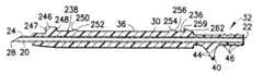
図1に示すように、血液回収キット10は、被覆可能な針アセンブリ12と、針アセンブリ12から延びる弾性チューブ14と、弾性チューブ14に取り付けられた固定部材16とを備えている。血液回収キット10の被覆可能な針アセンブリ12を図2から図9に詳細に示す。針アセンブリ12は、針状カニューレ20と、ハブ30と、外側シールド部材50とを有する。固定部材16は、従来技術に開示された通り、血液回収に使用される受け具(図示せず)に接続可能である。
【0016】
針状カニューレ20は、基端部22と、基端部22に対向する先端部24と、針状カニューレ20内を基端部22から先端部24に延びる管腔部26とを有する。針状カニューレ20の先端部24は傾斜しており、静脈穿刺部などの先鋭な穿刺部28が形成されている。穿刺部28は、静脈など、患者の血管に穿刺するためのものであり、静脈穿刺の間、針の挿入を容易にし、かつ、患者への負担が最小限になるよう設計されている。血液回収キット10の使用に先立って、穿刺部28を保護するため、針状カニューレ20の先端部24を覆うように着脱可能な保護カバー(図示せず)を設けてもよい。
【0017】
針アセンブリ12には、ハブ30が設けられている。ハブ30は熱可塑性材料で成形された一体構造をしているのが好ましい。ハブ30は、略長尺の筒体をしており、基端部32と、先端部34と、外面36と、基端部32から先端部34に延びる内側通路38とを有する。針状カニューレ20は、その先端部24が、ハブ30の先端部34から延びた状態で、ハブ30の内側通路38内において、該内側通路38に対し相対的に位置決めされている。針状カニューレ20とハブ30は、適当な医療用接着剤などで固定接着された別体であるのが好ましい。図2に示すように、ハブ30には、その先端部34に隣接した位置に、針状カニューレ20の基端部22が当接する規制部293を設けるのが好ましい。または、図3に示すように、針状カニューレ20は、ハブ30の長さ全体にわたって、ハブ30の基端部32に向かって延びるような構造でもよい。
【0018】
ハブ30の基端部32は、血液回収キット10の弾性チューブ14と接続可能な構成となっている。ハブ30には、弾性チューブ14に接続するように、その基端部32の外面36の周面に沿って複数のリブ46が形成されているのが好ましい。
【0019】
さらに、ハブ30の外面36上には、基端部32に隣接し、リブ46から離間した位置で外向きに延びている第1タブ40が設けられている。すなわち、第1タブ40は、ハブ30と弾性チューブ14との結合面の前方位置で、ハブ30の外面36から外向きに延びている。この状態で、針アセンブリ12が血液回収キット10内の第1チューブ14に組付けられると、弾性を有する第1タブ40はユーザの指で操作可能となる。
【0020】
第1タブ40は、基端部32に隣接したハブ30の底部において、外面36から延びている。さらに、第1タブ40は、弾性チューブ14に向かって延びているのが望ましい。第1タブ40には、ユーザの指と摩擦係合するよう、その斜面42に突起44が形成されている。
【0021】
針アセンブリ12は、さらに、中空の外側シールド部材50を有する。外側シールド部材50はハウジング52を備えている。ハウジング52は、基端部54と、先端部56と、基端部54と先端部56との間に延びる内側通路58とを備えた、熱可塑性材料で成形された一体構造であるのが好ましい。また、ハウジング52の内壁には内面60が形成されている。
【0022】
外側シールド部材50は、さらに、基端部54付近で、ハウジング52の頂部から外側に延びる第2タブ62を有する。第2タブ62は、外側シールド部材50の先端部56に向かって外側シールド部材50から外側に延びている。第2タブ62の傾斜面64には、ユーザの親指と摩擦係合する突起66が形成されている。
【0023】
外側シールド部材50は、ハブ30の先端部34と同軸上でこれを包囲するような構成となっている。この状態で、上記ハブ30の第1タブ40が外側シールド部材50の基端部54を超えて配設されるように、ハブ30の基端部32は、外側シールド部材50の基端部54を超えて延びている。さらに、外側シールド部材50の内面60は、ハブ30の外面36と協働係合している。外側シールド部材50は、第1タブ40が外側シールド部材50の基端部54から露出し、かつ、穿刺端部28が外側シールド部材50の先端部56から露出する退避位置と、針状カニューレ20の穿刺端部28と先端部24が、外側シールド部材50によって被覆される伸張位置との間を移動可能な構成となっている。
【0024】
第1タブ40と第2タブ62は、それらに対し逆方向に働く力が加わると、外側シールド部材50が退避位置から伸張位置に、すなわち、矢印100方向、針状カニューレ20の先端部24に向けて移動するような構成となっている。第1タブ40に設けられた突起44と第2タブ62に設けられた突起66は、それぞれ、ユーザの親指以外の指とユーザの親指と摩擦係合することによって、外側シールド部材50が退避位置から伸張位置に移動する構成となっている。
【0025】
外側シールド部材50は、さらに、外側シールド部材50の両側から横方向に延びるウィング状の1対の安定装置(翼部)68を備えている。これによって、血液回収キット10はバタフライ状のウィングアセンブリとなる。翼部68は、血液回収の間、針アセンブリ12と血液回収キット10を位置決めし、また、患者の肌面に対し平行に設置するようにするものである。翼部68は、静脈穿刺の間、針アセンブリ12の位置決め及び設置が容易になるよう、少なくとも1つ、好ましくはその両方が互いに接近接触するよう曲げることが可能となるように、弾性材料で構成されるのが望ましい。
【0026】
また、外側シールド部材50のハウジング52には、好ましくは、ハウジング52の少なくとも1側面において、より好ましくは、ハウジング52の両側面において、当該両側面に沿って延びる切り欠き部70が形成されている。切り欠き部70には、弾性指あて部72が形成され、これは、外側シールド部材50が退避位置から伸張位置に移動する間、径方向外向きに撓み、その結果、外側シールド部材50がハブ30に対し、その協働面において摺動係合するようにされている。
【0027】
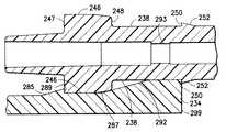
特に好ましい実施態様として、ハブ30の外面36及び外側シールド部材50の内面60には、これら外面36と内面60との間を所定の様態で協働する軸方向の動きが与えられるよう複数の対応する溝と斜面とが形成されている。例えば、図2から図6に示す通り、ハブ30の外面35には、比較的大径の前肩部246が設けられている。前肩部246は、前面(当接面)247と後当接面248とを備えて形成されている。前肩部246の直後ろには、その一面が後当接面248となり、もう一方の面が傾斜面252の端面(後当接面)250となる第1の溝238が設けられている。傾斜面252は、前肩部246より小さな径を有し、第1の溝238から下向きに傾斜している。傾斜面252は、ハブ30の外面36によって形成される長い谷部242で終端が形成されている。谷部242は、第1の溝238と実質的に等しく、比較的一定の径を有している。谷部242は、ハブ30の先端部34から離れ、基端部32に向かうにつれて、その径が増加する傾斜面254で終端が形成されている。傾斜面254は第2の溝236に向けて下向きに傾斜する傾斜面256へと続いている。第2の溝236は、谷部242の径よりわずかに大きい径に形成され、後当接面259で終端が形成されている。後当接面259は、後傾斜面262の終面でもあり、この後傾斜面262は、ハブ30の基端部32に沿って延びる延長部264で終端が形成されている。第1タブ40及びリブ46は、ハブ30の基端部32に沿って延びる延長部264において、ハブ30から延びている。
【0028】
図3に最もよく示されるように、ハブ30は、外側シールド部材50の内側で回転しないよう、非円筒状をしているのが好ましい。このような非円筒形状によって、前肩部246及び傾斜面252、254,256,262は、ハブ30の外面36の底部に現れないこととなる。したがって、本明細書において「径」の寸法を表す場合、「径」という用語は、断面の相対的な寸法を示すような広義の意味で使用される。
【0029】
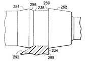
図7から図9を参照して、外側シールド部材50の好ましい実施態様を詳述する。外側シールド部材50のハウジング52は、好ましくは、平らな底面295を有する、断面略半円状である。平らな底面295は、外側シールド部材50の先端部56から離れるにつれ、2.5°の傾斜面に沿って、その底部の厚みが増加するような先細り形状(図8参照)であるのが好ましい。ハブ50と針状カニューレ20が外側シールド部材50内に位置決めされると、針状カニューレ20は、好ましくは約2.5°の傾斜角で下向きに向かい、その結果、針状カニューレ20は、患者の静脈に容易にかつ不快感を与えることなく挿入されることとなる。
【0030】
ハウジング52の内面60は、ハブ30の前肩部246の外径より僅かに大きい。基端部54に向かうにつれて、ハウジング52の内面には2つの傾斜面285、292が形成される。必要に応じて、傾斜面285の代わりに傾斜のない突起を設けてもよい。拡大図面である図9に詳細に示すとおり、傾斜面285によって、ハウジング52は、外側シールド部材50の基端部54に向かうにつれて、その内径が減少する。傾斜面285は当接面289で終端部が形成され、ここから、ハブ30の肩部246の外径に略等しい内径を有する平面287へと続く。平面287は、同じく、外側シールド部材50の基端部54に向かうにつれて、その内径が減少する傾斜面292で終端部が形成されている。傾斜面292の端部の内径は、傾斜面285の内径より実質的に小さい。外側シールド部材50の内面60は、ハウジング52の基端部54に後面299が設けられた状態で、前肩部246の径より実質小さい径の平らな突起234で終端が形成される。
【0031】
血液回収キット10は図1に示した状態で実質包装可能となる。すなわち、血液回収キット10は、組み立てられた針アセンブリ12と、針アセンブリ12から伸張し固定部材16に接続された弾性チューブ14とを備える。使用に先立って、血液回収キット10はパッケージから外される。パッケージから外された後、血液回収キット10は他の適当な医療器具に組み付けられ使用可能となる。固定部材16は、針状カニューレ20内において、管腔部26と連通し流体供給可能な状態で、患者以外の対象物に使用される針アセンブリ及び針ホルダなどの適当な受け具へ接続されるようになっている。
【0032】
血液回収キット10を使用可能な状態にするには、ユーザは血液回収キット10の針アセンブリ12部分を握り、保護カバー(図示せず)を外して、針状カニューレ20の穿刺端部28を露出する。この状態で、医療従事者は、針状カニューレ20の先端部24に設けられた穿刺端部28を、患者の所定の血管に穿刺可能となる。この位置決めの間、針アセンブリ12の位置決め及び、設置を容易にするため、少なくとも1つの翼部68はユーザの指によって他方の翼部68に向かって内向きに折り曲げ可能となる。すべての所望の血液サンプルを取り出すなどの処置完了後、針状カニューレ20を患者の血管から引き抜く。針状カニューレ20を患者の体内から引き抜いた後、針アセンブリ12の安全装置は作動する。
【0033】
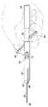
特に、図10に示す通り、ユーザは、親指を第1タブ40に当て、人さし指を第2タブ62に当てた状態で、すなわち、片手で針アセンブリ12を握る。第1タブ40と第2タブ62には、それぞれユーザの親指と人さし指を介して相反する方向に働く外力が与えられる。このように対向する力によって、外側シールド部材50は退避位置から伸張位置に矢印100の方向に移動する。その結果、針状カニューレ20の穿刺端部28は、図11に示した伸張位置で、外側シールド部材50によって安全にシールド(被覆)される。このような状態に置かれた血液回収キット10は適宜廃棄可能となる。
【0034】
上述した通り、ハブ30の外面36と外側シールド部材50の内面60に協働係合する複数の対応する溝と斜面が設けられている実施態様においては、傾斜面256を摺動する際、突起234を乗り越えるための初期の力が必要となる。このような動きを補助するべく、外側シールド部材50のハウジング52から径方向外向きに撓む弾性指あて部72を設け、これによって、突起234に抗する力を減少し、外側シールド部材50がハブ30に沿って軸方向に動くような構成とするのが好ましい。突起234が一旦傾斜面256と摺動接触し始めると、外側シールド部材50がハブ30の谷部242を乗り越えて摺動するのに殆ど外力は不要となる。傾斜面285が前肩部246を乗り越える場合と同様、ハブ30の傾斜面252がハウジング52の傾斜面285を乗り越える際、外力が必要となる。協働係合面を有する針アセンブリ12の上記構造は、第1タブ40と第2タブ62にそれぞれ異なる力を付与することによって、外側シールド部材50を退避位置と伸張位置との間で適切に動かすのに効果的である。特に、径方向に撓む弾性指当て部72と、傾斜面285と前肩部246端部の丸みのある斜面特性によって、傾斜面285は、傾斜面285が前肩部246を乗り越えるまで、外側シールド部材50の当接面289が、ハブ30の前肩部246の当接面247と当接した状態で、前肩部246上を摺動することとなる。これと同時に、外側シールド部材50の後面299がハブ30の後当接面250に当接し、かつ、前肩部246が平面287に接触した状態で、突起234は第1の溝238に嵌入される。上記ロック状態において、針状カニューレ20の穿刺端部28は外側シールド部材50によってその全体を確実に被覆される。
図6に示すとおり、突起234と前肩部246との相対的な大きさの違いによって、外側シールド部材50がハブ30から前向きに引っ張られるのを抑止しつつ、また、針状カニューレ20が露出する退避位置に戻るのを抑止するという、(当接面289が前肩部246に当接し、後面299が後当接面250に当接するという)2つの係止効果が生まれる。
【0035】
本発明に係る針アセンブリを、血液回収システムに関して使用される一実施態様として説明したが、本発明に係る針アセンブリは、針アセンブリとの使用が公知である従来の静脈注射器セットと組み合わせた、他の医療器具と組み合わせても使用可能である。
【0036】
本発明は多くの異なる実施態様によって満足されるものである。本発明の好ましい実施態様は、図面及び本明細書に詳細に説明した通りであるが、本発明の開示内容は、本発明の原理の一例として考慮されるべきであり、例示した実施態様に限定されるものではない。本発明の主旨を逸脱しない範囲で、当業者がさまざまな他の実施態様に変更実施することは全て本発明の技術範囲に包含される。本発明の範囲は添付の特許請求の範囲及びその均等物によって評価されるものである。
【0037】
【発明の効果】
以上説明したように本発明の血液回収キット及び、これに使用される針アセンブリは、外面を有して延びる筒体と、基端部と、先端部と、内部を貫通する通路とを有するハブを備えている。このハブには、さらにユーザの指に係合するように、上記筒体の基端部から外向きに延びる第1タブが設けられている。また、上記ハブの先端部は、針状カニューレを支持しており、この針状カニューレの先端部には、穿刺端部が設けられている。
【0038】
また、上記針アセンブリは、上記ハブの外面を同軸上に包囲するように配設された中空の外側シールド部材を備えており、この外側シールド部材は、基端部、先端部、その内部を貫通する通路とを備えたハウジングと、ユーザの親指と係合するように上記ハウジングから外向きに延びる第2タブとを備えている。上記第1タブは、外側シールド部材の基端部から露出する位置で上記筒体から延びており、上記ハウジングは、上記ハブの外面と協働係合する内面を備えている。
【0039】
このように構成された針アセンブリは、上記第1タブと第2タブに対してそれぞれ相対向する向きの外力を付与することにより、上記外側シールド部材が上記針状カニューレの先端部側へ移動して、当該外側シールド部材が針上カニューレの穿刺端部が露出させる退避位置から、上記針状カニューレの穿刺端部を被覆する伸張位置まで移動するように構成されている。
【0040】
以上のように本発明の針アセンブリは、上記第1タブと第2タブに対してそれぞれ相対向する向きの外力を付与するといった簡易的な操作によって、上記伸張位置へ変位された外側シールド部材により針状カニューレの穿刺端部を被覆することができる。
【0041】
また、上記ハブの外面を同軸上に被覆するように形成された外側シールド部材を採用することにより、上記のように針状カニューレの穿刺端部を被覆することが可能となる結果、針アセンブリ自体の構成を簡素化することが可能となり、製造が容易で、かつ安価な針アセンブリを具現化することができる。
【0042】
さらに、上記のようにハウジングの内面とハブの外面とが互いに協働係合するように構成されているため、上記外側シールド部材が伸張位置へ変位される場合に、必要以上に変位してしまうといった不具合を防止することが可能となる結果、安全に針状カニューレの穿刺端部を被覆することができる。
【図面の簡単な説明】
【図1】 本発明に係る血液回収キットの斜視図である。
【図2】 針状カニューレを受け入れるハブの平面図である。
【図3】 針状カニューレを有するハブの側面図である。
【図4】 図2に示すハブに設けられた第2溝の側面図である。
【図5】 図2に示すハブの基端部を示す側面図である。
【図6】 図2に示すハブの先端部に設けられた第1溝の側面図である。
【図7】 本発明に係るウィング付き外側シールド部材の平面図である。
【図8】 図7に示す外側シールド部材の側面図である。
【図9】 図7に示す外側シールド部材の基端部の拡大平面図である。
【図10】 外側シールド部材が退避位置にある状態を示す、図1に示す血液回収キットの側面図である。
【図11】 外側シールド部材が伸張位置にある状態を示す、図1に示す血液回収キットの側面図である。
【符号の説明】
10 血液回収キット
12 針アセンブリ
14 弾性チューブ
20 針状カニューレ
22 基端部
24 先端部
28 穿刺部
30 ハブ
32 基端部
34 先端部
38 内側通路(通路)
40 第1タブ
42 傾斜面
44 突起
50 シールド部材
52 ハウジング
54 基端部
56 先端部
58 内側通路(通路)
60 内面
62 第2タブ
64 傾斜面
66 突起
68 翼部
70 切欠き部[0001]
BACKGROUND OF THE INVENTION
The present invention relates to a blood collection kit for safe and convenient needle handling. More particularly, the present invention relates to a blood collection kit comprising a needle assembly having a forward-movable safety shield member that protects a used needle tip.
[0002]
[Prior art]
A disposable medical device having a puncture member is generally used for drug administration or fluid recovery, such as a blood recovery needle, a fluid processing needle, and an assembly thereof. In the current medical field, fluid containers and needle assemblies used in such systems are desired to be inexpensive and easy to dispose of. Therefore, in a conventional blood collection system, for example, a detachable disposable needle and a fluid collection tube can be attached, and a durable and reusable shape holder is usually used. . This type of blood collection system is configured to be assembled before use and disassembled after use. Therefore, in these blood collection systems, relatively expensive holders are repeatedly used, and relatively inexpensive needles and / or fluid collection tubes are replaced. In addition to being able to reduce the cost of collecting blood samples, these blood collection systems also have the advantage of reducing the generation of hazardous medical waste.
[0003]
Blood collection kits or intravenous (IV) kits generally include a needle cannula having a proximal end, a sharp distal end, and a lumen extending therebetween. The proximal end of the needle cannula is securely attached to a plastic hub having a central passage that communicates with the lumen of the cannula. A flexible thermoplastic tube is connected to the hub, and the thermoplastic tube communicates with the lumen of the needle cannula. A fixing member for connecting the needle cannula to the blood collection tube or other receptacle may be provided at one end of the plastic tube disposed on the opposite side of the needle cannula. The structure of the fixing member is set according to the characteristics of the receiving member to be connected.
[0004]
In order to prevent accidents such as scratches caused by needle sticks, it is important to protect used needle tips. From the standpoint of preventing disease infection and transmission, methods and devices that surround used disposable needles are extremely important and the demand for such methods and devices is high. For example, some injection needle assemblies use a safety covering member that is movable within the covering member to make a covering engagement with a used needle cannula to prevent unintentional needle sticks.
[0005]
The following Patent Document 1, Patent Document 2, and Patent Document 3 disclose needle devices with safety wings used for blood collection kits or fluid injection kits. The safety injection needle devices disclosed in these patents include an inner tube and an outer tube having cooperating surfaces that come into contact with each other, and the cooperating surfaces include grooves and bevels that mesh with each other. By applying forces acting in opposite directions to the inner and outer tubes, the outer tube is forced to move along its inclined surface while engaging with the groove of the inner tube, and finally the outer shield member is placed at the covering position. And it locks in the said predetermined position centering on a needle point. However, the cooperating surfaces of the outer and inner tubes are frictionally engaged, and considerable force is required to release the frictional engagement. Furthermore, as a result of being configured as described above, it is difficult to hold the injection needle device with an appropriate grip force in order to forcibly separate the outer and inner tubes.
[0006]
The following Patent Document 4 discloses a needle guard. A protrusion called a “thumb handle” is provided on the outside of the needle guard. When the user presses the protrusion with the thumb, the user can operate with one hand to insert the injection needle and the needle mount into the outer guard. Easy structure. However, in order to retract the needle as described above, it is necessary for the user to grasp the elastic tube in the palm, and an effective holding surface is provided for holding the needle device in a predetermined position when the needle is retracted. It will not be possible. As a result, the elastic tube may be detached from the needle device when the needle is withdrawn.
[0007]
[Patent Document 1]
US Pat. No. 5,085,639
[Patent Document 2]
US Pat. No. 5,088,982
[Patent Document 3]
US Pat. No. 5,154,699
[Patent Document 4]
US Pat. No. 6,165,157
[0008]
[Problems to be solved by the invention]
In view of such circumstances, the present invention provides a needle assembly used in a blood collection kit that covers a used needle tip safely and effectively, which is easy to manufacture, inexpensive and easy to operate. It is.
[0009]
[Means for Solving the Problems]
The present invention relates to the coatable blood collection kit described above and the needle assembly used in such a blood collection kit. That is, the needle assembly according to the present invention includes a hub having a cylindrical body extending with an outer surface, a proximal end portion, a distal end portion, and a passage penetrating the inside. The hub is further provided with a first tab extending outward from the base end of the cylinder so as to engage with a user's finger. The tip of the hub supports a needle cannula, and the needle cannula has a piercing end at its tip. A hollow outer shield member coaxially surrounds the distal end portion of the cylindrical body of the hub, and the outer shield member has a base end portion, a distal end portion, and a housing having a passage penetrating through the housing, A second tab is provided extending outwardly from the housing for engaging the user's thumb. The first tab extends from the cylindrical body of the hub at a position exposed from the base end of the outer shield member, and the housing of the outer shield member cooperates with the outer surface of the hub. Have mating inner surfaces.
[0010]
In the above-described needle assembly according to the present invention, when the first tab and the second tab receive an external force in directions opposite to each other, the outer shield member exposes the puncture end of the needle cannula. From the retracted position, the outer shield member is configured to move toward an extended position that covers the puncture end of the needle cannula, that is, toward the distal end of the needle cannula.
[0011]
In the needle assembly according to the present invention described above, the first tab extends from the bottom of the hub, and the second tab extends from the top of the housing of the outer shield member at a position adjacent to the first tab. It is preferable. That is, the first tab and the second tab are configured to engage with the user's thumb and fingers other than the thumb, respectively, so that the outer shield member moves from the retracted position to the extended position. It becomes possible to move to (operating position).
[0012]
In the needle assembly according to the present invention described above, the outer surface of the hub has a series of grooves and inclined surfaces, and the inner surface of the outer shield member is configured to cooperate with the outer surface of the hub. It is preferable. By providing such corresponding grooves and inclined surfaces, frictional engagement is imparted between the outer shield member and the hub, and as a result, the outer shield member is placed in the retracted position until an external force is applied. Movement between the operating positions is prevented.
[0013]
The present invention further relates to a blood collection kit. The blood recovery kit according to the present invention includes the above-described needle assembly according to the present invention, a fixing member for coupling the blood recovery kit to a receiving tool, and the blood recovery kit and the needle at the proximal end portion of the hub. And an elastic tube extending between the assembly and the assembly.
[0014]
DETAILED DESCRIPTION OF THE INVENTION
In the attached attached drawings in which common members are described with the same reference numerals, FIG. 1 shows a
[0015]
As shown in FIG. 1, the
[0016]
The
[0017]
The
[0018]
The
[0019]
Further, on the
[0020]
The
[0021]
[0022]
The
[0023]
The
[0024]
When a force acting in the opposite direction is applied to the
[0025]
The
[0026]
Further, the
[0027]
In a particularly preferred embodiment, the
[0028]
As best shown in FIG. 3, the
[0029]
A preferred embodiment of the
[0030]
The
[0031]
The
[0032]
To make the
[0033]
In particular, as shown in FIG. 10, the user holds the
[0034]
As described above, in embodiments where a plurality of corresponding grooves and bevels are provided for cooperating engagement with the
As shown in FIG. 6, the relative size difference between the
[0035]
While the needle assembly according to the present invention has been described as one embodiment for use with a blood collection system, the needle assembly according to the present invention is combined with a conventional intravenous syringe set known for use with a needle assembly, etc. It can also be used in combination with other medical devices.
[0036]
The present invention is satisfied by many different embodiments. Preferred embodiments of the present invention are as described in detail in the drawings and specification, but the disclosure of the present invention should be considered as an example of the principles of the present invention and limited to the illustrated embodiments. Is not to be done. It is within the technical scope of the present invention that a person skilled in the art can change and implement various other embodiments without departing from the spirit of the present invention. The scope of the invention is to be evaluated by the appended claims and their equivalents.
[0037]
【The invention's effect】
As described above, the blood collection kit of the present invention and the needle assembly used therefor are a hub having a cylindrical body extending with an outer surface, a proximal end portion, a distal end portion, and a passage extending therethrough. It has. The hub is further provided with a first tab extending outward from the base end of the cylinder so as to engage with the user's finger. The distal end portion of the hub supports a needle cannula, and the distal end portion of the needle cannula is provided with a puncture end portion.
[0038]
Further, the needle assembly includes a hollow outer shield member disposed so as to coaxially surround the outer surface of the hub, and the outer shield member penetrates the proximal end portion, the distal end portion, and the inside thereof. And a second tab extending outwardly from the housing to engage the user's thumb. The first tab extends from the cylindrical body at a position exposed from the proximal end portion of the outer shield member, and the housing includes an inner surface that cooperates with an outer surface of the hub.
[0039]
In the needle assembly configured in this manner, the outer shield member moves toward the distal end side of the needle cannula by applying external forces in opposite directions to the first tab and the second tab, respectively. Thus, the outer shield member is configured to move from a retracted position where the puncture end portion of the upper needle cannula is exposed to an extended position covering the puncture end portion of the needle cannula.
[0040]
As described above, the needle assembly according to the present invention is provided by the outer shield member displaced to the extended position by a simple operation such as applying external forces in opposite directions to the first tab and the second tab. The puncture end of the needle cannula can be covered.
[0041]
Further, by adopting an outer shield member formed so as to coaxially cover the outer surface of the hub, it becomes possible to cover the puncture end portion of the needle cannula as described above. As a result, the needle assembly itself The needle assembly can be simplified, and the needle assembly that is easy to manufacture and inexpensive can be realized.
[0042]
Further, since the inner surface of the housing and the outer surface of the hub are configured to cooperate with each other as described above, when the outer shield member is displaced to the extended position, it is displaced more than necessary. As a result, it is possible to safely cover the puncture end of the needle cannula.
[Brief description of the drawings]
FIG. 1 is a perspective view of a blood collection kit according to the present invention.
FIG. 2 is a plan view of a hub for receiving a needle cannula.
FIG. 3 is a side view of a hub having a needle cannula.
4 is a side view of a second groove provided in the hub shown in FIG. 2. FIG.
FIG. 5 is a side view showing a proximal end portion of the hub shown in FIG. 2;
6 is a side view of a first groove provided at the tip of the hub shown in FIG. 2. FIG.
FIG. 7 is a plan view of an outer shield member with wings according to the present invention.
FIG. 8 is a side view of the outer shield member shown in FIG.
9 is an enlarged plan view of a proximal end portion of the outer shield member shown in FIG.
10 is a side view of the blood collection kit shown in FIG. 1, showing a state in which the outer shield member is in the retracted position.
FIG. 11 is a side view of the blood collection kit shown in FIG. 1, showing a state in which the outer shield member is in the extended position.
[Explanation of symbols]
10 Blood collection kit
12 needle assembly
14 Elastic tube
20 Needle cannula
22 Base end
24 Tip
28 Puncture part
30 hub
32 Base end
34 Tip
38 Inside passage (passage)
40 First tab
42 Inclined surface
44 projections
50 Shield material
52 Housing
54 Base end
56 Tip
58 Inside passage (passage)
60 Inside
62 Second Tab
64 Inclined surface
66 protrusion
68 Wings
70 Notch
Claims (12)
Translated fromJapanese外面を有して延びる筒体と、基端部と、上記針状カニューレを支持する先端部と、内部を貫通する通路とを備えたハブであって、上記筒体の基端部から外方へ延びる第1タブをさらに備えたハブと、
基端部と、先端部と、上記基端部から上記先端部へ延びる通路とを有するハウジングと、上記ハウジングから外向きに延びる第2タブとを備えた中空の外側シールド部材であって、上記ハブの筒体の先端部を同軸上に包囲するとともに、上記ハブの筒体の外面と協働係合する内面を有する外側シールド部材とを備え、
上記筒体から延びる上記第1タブを上記外側シールド部材の上記基端部から露出させるとともに、上記針状カニューレの上記穿刺端部を上記外側シールド部材の上記先端部から露出させる退避位置と、上記針状カニューレの上記穿刺端部を覆う伸張位置との間で上記外側シールド部材が移動可能に構成されるとともに、
上記第1タブと上記第2タブとが互いに相対向する方向へ外力を受けた場合に、上記外側シールド部材が上記針状カニューレの上記先端部側へ移動して、当該外側シールド部材が上記退避位置から上記伸張位置へ移動するように構成され、
上記第1タブは、上記ハブの上記基端部において、上記ハブの基端部側に向けて上記ハブの上記筒体の底部から外向きに延び、上記ハブの先端側を向く傾斜面を有し、
上記第2タブは、上記外側シールド部材の上記基端部において、上記外側シールド部材の上記先端部に向けて上記外側シールド部材の上記ハウジングの頂部から外向きに延び、上記外側シールド部材の基端側を向く傾斜面を有することを特徴とする針アセンブリ。A needle cannula having a proximal end and a distal end having a puncture end;
A hub having a cylindrical body extending with an outer surface, a proximal end portion, a distal end portion supporting the needle cannula, and a passage penetrating through the interior, outward from the proximal end portion of the tubular body A hub further comprising a first tab extending to
A hollow outer shield member comprising a housing having a proximal end, a distal end, a passage extending from the proximal end to the distal end, and a second tab extending outward from the housing, An outer shield member that coaxially surrounds the tip of the hub cylinder and has an inner surface that cooperates with the outer surface of the hub cylinder,
A retracted position for exposing the first tab extending from the cylindrical body from the proximal end portion of the outer shield member and exposing the puncture end portion of the needle cannula from the distal end portion of the outer shield member; The outer shield member is configured to be movable between an extended position that covers the puncture end of the needle cannula, and
When the first tab and the second tab receive an external force in directions opposite to each other, the outer shield member moves toward the distal end side of the needle cannula, and the outer shield member retracts. Configured to move from a position to the extended position,
The first tab has an inclined surface that extends outward from the bottom of the cylindrical body of the hub toward the proximal end of the hub at the proximal end of the hub and faces the distal end of the hub. And
The second tab extends outward from the top of the housing of the outer shield member toward the distal end of the outer shield member at the proximal end of the outer shield member, and the proximal end of the outer shield member A needle assembly having an inclined surface facing sideways.
上記固定部材に結合される第1端部と第2端部とをその両側に有する弾性チューブと、
外面を有して延びる筒体と、上記弾性チューブの第2端部へ取付けられる基端部と、先端部と、内部を貫通する通路とを有するハブであって、当該ハブの基端部で上記筒体から外方へ延びるとともに、ユーザーの指と係合するように形成された第1タブをさらに備えたハブと、
基端部と、穿刺端部を有する先端部とを備え、上記ハブの上記先端部から延びる針状カニューレと、
基端部、先端部、内部を貫通する通路とを有するハウジングを含む中空の外側シールド部材とを備えた被覆可能な血液回収キットにおいて、
上記外側シールド部材は、上記ハブの上記第1タブが、上記外側シールド部材の上記基端部から露出するように、上記ハブの上記筒体の上記先端部を同軸上に囲み、
また、上記外側シールド部材は、上記針状カニューレの上記穿刺端部が上記外側シールド部材の上記先端部から露出する退避位置と、上記外側シールド部材が上記針状カニューレの上記穿刺端部を覆う伸張位置との間を移動するように構成され、
上記外側シールド部材の上記ハウジングは、上記ハブの上記外面と協働係合する内面と、ユーザの親指と係合するよう上記ハウジングから外向きに延びる第2タブとを有するとともに、
上記第1タブと上記第2タブとが互いに相対向する方向へ外力を受けた場合に、上記外側シールド部材が上記針状カニューレの上記先端部に向けて移動して、当該外側シールド部材が上記退避位置から上記伸張位置へ移動するように構成され、
上記第1タブは、上記ハブの上記基端部において、上記弾性チューブに向けて上記ハブの上記筒体の底部から外向きに延び、上記ハブの先端側を向く傾斜面を有し、
上記第2タブは、上記外側シールド部材の上記基端部において、上記外側シールド部材の上記先端部に向けて上記外側シールド部材の上記ハウジングの頂部から外向きに延び、上記外側シールド部材の基端側を向く傾斜面を有することを特徴とする被覆可能な血液回収キット。A fixing member for coupling with the receiver;
An elastic tube having a first end and a second end coupled to the fixing member on both sides thereof;
A hub having a cylindrical body extending with an outer surface, a proximal end attached to the second end of the elastic tube, a distal end, and a passage penetrating the interior, the proximal end of the hub A hub further extending from the cylindrical body and further including a first tab formed to engage with a user's finger;
A needle cannula comprising a proximal end and a distal end having a puncture end and extending from the distal end of the hub;
In a coatable blood collection kit comprising a hollow outer shield member including a housing having a proximal end, a distal end, and a passage extending through the interior,
The outer shield member coaxially surrounds the distal end portion of the cylindrical body of the hub such that the first tab of the hub is exposed from the proximal end portion of the outer shield member,
The outer shield member includes a retracted position where the puncture end portion of the needle cannula is exposed from the tip end portion of the outer shield member, and the outer shield member extends to cover the puncture end portion of the needle cannula. Configured to move between positions,
The housing of the outer shield member has an inner surface cooperating with the outer surface of the hub and a second tab extending outwardly from the housing to engage a user's thumb;
When the first tab and the second tab receive an external force in a direction opposite to each other, the outer shield member moves toward the distal end portion of the needle cannula, and the outer shield member Configured to move from the retracted position to the extended position;
The first tab has an inclined surface that extends outward from the bottom of the cylindrical body of the hub toward the elastic tube at the base end portion of the hub and faces the distal end side of the hub,
The second tab extends outward from the top of the housing of the outer shield member toward the distal end of the outer shield member at the proximal end of the outer shield member, and the proximal end of the outer shield member A coatable blood collection kit, characterized by having an inclined surface facing the side.
Applications Claiming Priority (2)
| Application Number | Priority Date | Filing Date | Title |
|---|---|---|---|
| US10/100,307 | 2002-03-15 | ||
| US10/100,307US6623461B1 (en) | 2002-03-15 | 2002-03-15 | Forward shielding safety device |
Publications (2)
| Publication Number | Publication Date |
|---|---|
| JP2003265610A JP2003265610A (en) | 2003-09-24 |
| JP4564710B2true JP4564710B2 (en) | 2010-10-20 |
Family
ID=28039775
Family Applications (1)
| Application Number | Title | Priority Date | Filing Date |
|---|---|---|---|
| JP2002342025AExpired - LifetimeJP4564710B2 (en) | 2002-03-15 | 2002-11-26 | Safety device covering the front part of the needle |
Country Status (7)
| Country | Link |
|---|---|
| US (2) | US6623461B1 (en) |
| EP (1) | EP1352668B1 (en) |
| JP (1) | JP4564710B2 (en) |
| AU (1) | AU2003200121B2 (en) |
| CA (1) | CA2407441A1 (en) |
| DE (1) | DE60217643T2 (en) |
| ES (1) | ES2278859T3 (en) |
Cited By (1)
| Publication number | Priority date | Publication date | Assignee | Title |
|---|---|---|---|---|
| KR20160150291A (en)* | 2014-10-24 | 2016-12-29 | 겜티어 메디컬 (상해) 인코퍼레이션 | Disposable anti-acupuncture intravenous infusion puncture needle |
Families Citing this family (45)
| Publication number | Priority date | Publication date | Assignee | Title |
|---|---|---|---|---|
| US20030220587A1 (en)* | 2002-05-23 | 2003-11-27 | Becton Dickinson And Company | Medical device |
| US11083841B2 (en) | 2002-08-09 | 2021-08-10 | Fenwal, Inc. | Needle protector, needle assembly and fluid processing set including the same |
| US7704229B2 (en)* | 2005-02-03 | 2010-04-27 | Medtronic Minimed, Inc. | Insertion device |
| EP1907042B1 (en) | 2005-07-06 | 2009-03-11 | Vascular Pathways Inc. | Intravenous catheter insertion device and method of use |
| JP2009520508A (en)* | 2005-09-22 | 2009-05-28 | タイコ・ヘルスケアー・グループ・エルピー | Manual retractable safety needle with rigid blade structure |
| US7753878B2 (en) | 2005-09-22 | 2010-07-13 | Tyco Healthcare Group Lp | Safety needle with lockout mechanism |
| US8118786B2 (en)* | 2006-03-29 | 2012-02-21 | Kawasumi Laboratories, Inc. | Guarded medical winged needle assembly |
| US8888713B2 (en) | 2007-03-07 | 2014-11-18 | Becton, Dickinson And Company | Safety blood collection assembly with indicator |
| EP3108812B1 (en) | 2007-03-07 | 2020-04-29 | Becton, Dickinson and Company | Safety blood collection assembly with indicator |
| EP2150304B1 (en) | 2007-05-07 | 2010-12-01 | Vascular Pathways Inc. | Intravenous catheter insertion and blood sample devices and method of use |
| US8603009B2 (en) | 2008-03-07 | 2013-12-10 | Becton, Dickinson And Company | Flashback blood collection needle |
| US8795198B2 (en) | 2008-03-07 | 2014-08-05 | Becton, Dickinson And Company | Flashback blood collection needle |
| US8323249B2 (en) | 2009-08-14 | 2012-12-04 | The Regents Of The University Of Michigan | Integrated vascular delivery system |
| US8216186B2 (en)* | 2010-03-10 | 2012-07-10 | Becton, Dickinson And Company | Catheter device with hooding feature |
| US8932258B2 (en) | 2010-05-14 | 2015-01-13 | C. R. Bard, Inc. | Catheter placement device and method |
| US9872971B2 (en) | 2010-05-14 | 2018-01-23 | C. R. Bard, Inc. | Guidewire extension system for a catheter placement device |
| US9950139B2 (en) | 2010-05-14 | 2018-04-24 | C. R. Bard, Inc. | Catheter placement device including guidewire and catheter control elements |
| US11925779B2 (en) | 2010-05-14 | 2024-03-12 | C. R. Bard, Inc. | Catheter insertion device including top-mounted advancement components |
| US10384039B2 (en) | 2010-05-14 | 2019-08-20 | C. R. Bard, Inc. | Catheter insertion device including top-mounted advancement components |
| WO2011146769A2 (en) | 2010-05-19 | 2011-11-24 | Tangent Medical Technologies Llc | Integrated vascular delivery system |
| US8814833B2 (en) | 2010-05-19 | 2014-08-26 | Tangent Medical Technologies Llc | Safety needle system operable with a medical device |
| EP2585145B1 (en) | 2010-08-19 | 2014-03-05 | West Pharmaceutical Services, Inc. | Rigid needle shield |
| EP2946804B1 (en)* | 2010-09-07 | 2017-11-22 | Poly Medicure Limited | Needle protector assembly |
| BRDI7102911S (en)* | 2010-12-14 | 2014-06-10 | Poly Medicure Ltd | CONFIGURATION APPLIED ON BLOOD COLLECTION SAFETY SET |
| US8690833B2 (en) | 2011-01-31 | 2014-04-08 | Vascular Pathways, Inc. | Intravenous catheter and insertion device with reduced blood spatter |
| ES2835652T3 (en) | 2011-02-25 | 2021-06-22 | Bard Inc C R | Medical component insertion device including a retractable needle |
| USD903101S1 (en) | 2011-05-13 | 2020-11-24 | C. R. Bard, Inc. | Catheter |
| JP5790972B2 (en) | 2011-06-07 | 2015-10-07 | 株式会社ジェイ・エム・エス | Indwelling needle device |
| JP5854271B2 (en)* | 2012-02-17 | 2016-02-09 | 株式会社ジェイ・エム・エス | Indwelling needle device |
| WO2014120741A1 (en) | 2013-01-30 | 2014-08-07 | Vascular Pathways, Inc. | Systems and methods for venipuncture and catheter placement |
| WO2014121119A1 (en) | 2013-02-01 | 2014-08-07 | Nxstage Medical, Inc. | Safe cannulation devices, methods, and systems |
| SE1350137A1 (en)* | 2013-02-05 | 2014-08-06 | Vigmed Ab | needle device |
| CA2937744C (en) | 2014-02-04 | 2022-08-09 | Icu Medical, Inc. | Self-priming systems and methods |
| PT3045113T (en)* | 2014-04-11 | 2018-05-28 | Shanghai Jinta Medical Co Ltd | Safety blood-collection needle |
| WO2016037127A1 (en) | 2014-09-05 | 2016-03-10 | C.R. Bard, Inc. | Catheter insertion device including retractable needle |
| GB2532983B (en) | 2014-12-04 | 2016-10-26 | Owen Mumford Ltd | Needle assemblies |
| USD903100S1 (en) | 2015-05-01 | 2020-11-24 | C. R. Bard, Inc. | Catheter placement device |
| CN113350614A (en) | 2015-05-15 | 2021-09-07 | C·R·巴德股份有限公司 | Catheter placement device including extendable needle safety feature |
| JP6664270B2 (en)* | 2016-04-26 | 2020-03-13 | 株式会社トップ | Medical needle with protector |
| US10493262B2 (en) | 2016-09-12 | 2019-12-03 | C. R. Bard, Inc. | Blood control for a catheter insertion device |
| EP3585471B1 (en) | 2017-03-01 | 2025-01-01 | C. R. Bard, Inc. | Catheter insertion device |
| ES2980192T3 (en) | 2018-03-07 | 2024-09-30 | Bard Access Systems Inc | Guidewire advancement and blood reflux systems for a medical device insertion system |
| USD921884S1 (en) | 2018-07-27 | 2021-06-08 | Bard Access Systems, Inc. | Catheter insertion device |
| CA3151126A1 (en) | 2019-08-19 | 2021-02-25 | Becton, Dickinson And Company | Midline catheter placement device |
| US11896787B2 (en)* | 2019-09-30 | 2024-02-13 | Becton, Dickinson And Company | Anti-rotation catheter devices, systems, and methods |
Family Cites Families (27)
| Publication number | Priority date | Publication date | Assignee | Title |
|---|---|---|---|---|
| US3595230A (en)* | 1968-07-25 | 1971-07-27 | Abbott Lab | Intravenous catheter placement unit with tubular guide sheath |
| US4326519A (en)* | 1980-02-21 | 1982-04-27 | Abbott Laboratories | Venipuncture device |
| USRE36447E (en) | 1985-07-29 | 1999-12-14 | Btg International Limited | Safety device for hypodermic needle or the like |
| US4826490A (en) | 1985-07-29 | 1989-05-02 | National Research Development Corporation | Safety device for hypodermic needle or the like |
| US4737144A (en)* | 1987-03-09 | 1988-04-12 | Choksi Pradip V | Syringe with selectively exposed and enveloped needle |
| US4950252A (en)* | 1987-11-02 | 1990-08-21 | Luther Medical Products, Inc. | Single hand actuated locking safety catheter and method of use |
| US5154699A (en) | 1988-03-01 | 1992-10-13 | Ryan Medical, Inc. | Safety winged needle device for use with fistulas |
| US5088982A (en) | 1988-03-01 | 1992-02-18 | Ryan Medical, Inc. | Safety winged needle medical devices |
| US5085639A (en) | 1988-03-01 | 1992-02-04 | Ryan Medical, Inc. | Safety winged needle medical devices |
| JP2673682B2 (en) | 1988-03-03 | 1997-11-05 | テルモ株式会社 | Winged medical needle |
| JPH0246861A (en)* | 1988-08-08 | 1990-02-16 | Haruo Yoshida | Injection device for preventing infection |
| US5266072A (en) | 1988-09-30 | 1993-11-30 | Utterberg David S | Guarded winged needle assembly |
| WO1990003196A1 (en) | 1988-09-30 | 1990-04-05 | Utterberg David S | Guarded winged needle assembly |
| US4964854A (en)* | 1989-01-23 | 1990-10-23 | Luther Medical Products, Inc. | Intravascular catheter assembly incorporating needle tip shielding cap |
| NL9002552A (en)* | 1990-09-05 | 1992-04-01 | Advanced Protective Injection | INFUSION OR TRANSFUSION NEEDLE ASSEMBLY. |
| US5120320A (en) | 1991-02-13 | 1992-06-09 | Becton, Dickinson And Company | I.V. infusion or blood collection assembly with automatic safety feature |
| US5290264A (en) | 1991-09-03 | 1994-03-01 | Utterberg David S | Grippable guard for needle assembly |
| US5192275A (en) | 1991-09-18 | 1993-03-09 | Becton, Dickinson And Company | IV infusion or blood collection guard assembly |
| US5312359A (en)* | 1991-12-03 | 1994-05-17 | Wallace Henry G | Intravenous cannula insertion assembly with protective shield |
| AU654464B3 (en) | 1994-04-20 | 1994-11-03 | Noble House Group Pty Ltd | Protective sheath |
| US5562637A (en) | 1994-07-15 | 1996-10-08 | Utterberg; David S. | Needle protector sheath |
| US5562636A (en) | 1994-07-15 | 1996-10-08 | Utterberg; David S. | Needle protector sheath |
| US5498241A (en)* | 1994-12-08 | 1996-03-12 | Abbott Laboratories | Winged needle assembly with protective member |
| CA2169220A1 (en)* | 1995-03-16 | 1996-09-17 | Greg L. Brimhall | Control forward introducer needle and catheter assembly |
| US5738665A (en)* | 1996-09-26 | 1998-04-14 | Becton, Dickinson And Company | Shield and actuator for needles |
| WO1998057689A1 (en)* | 1997-06-16 | 1998-12-23 | Becton Dickinson And Company | Shield for catheter introducer needles |
| US5997507A (en)* | 1998-08-07 | 1999-12-07 | Dysarz; Edward D. | Biased spring hard needle retractable IV catheter |
- 2002
- 2002-03-15USUS10/100,307patent/US6623461B1/ennot_activeExpired - Lifetime
- 2002-10-10CACA002407441Apatent/CA2407441A1/ennot_activeAbandoned
- 2002-11-12ESES02025276Tpatent/ES2278859T3/ennot_activeExpired - Lifetime
- 2002-11-12DEDE60217643Tpatent/DE60217643T2/ennot_activeExpired - Lifetime
- 2002-11-12EPEP02025276Apatent/EP1352668B1/ennot_activeExpired - Lifetime
- 2002-11-26JPJP2002342025Apatent/JP4564710B2/ennot_activeExpired - Lifetime
- 2003
- 2003-01-13AUAU2003200121Apatent/AU2003200121B2/ennot_activeExpired
- 2003-07-28USUS10/628,223patent/US7060055B2/ennot_activeExpired - Lifetime
Cited By (2)
| Publication number | Priority date | Publication date | Assignee | Title |
|---|---|---|---|---|
| KR20160150291A (en)* | 2014-10-24 | 2016-12-29 | 겜티어 메디컬 (상해) 인코퍼레이션 | Disposable anti-acupuncture intravenous infusion puncture needle |
| KR101893804B1 (en)* | 2014-10-24 | 2018-08-31 | 겜티어 메디컬 (상해) 인코퍼레이션 | Disposable anti-acupuncture intravenous infusion puncture needle |
Also Published As
| Publication number | Publication date |
|---|---|
| EP1352668B1 (en) | 2007-01-17 |
| AU2003200121A1 (en) | 2003-10-02 |
| US20040024370A1 (en) | 2004-02-05 |
| EP1352668A2 (en) | 2003-10-15 |
| ES2278859T3 (en) | 2007-08-16 |
| DE60217643T2 (en) | 2007-10-11 |
| US20030176842A1 (en) | 2003-09-18 |
| US7060055B2 (en) | 2006-06-13 |
| US6623461B1 (en) | 2003-09-23 |
| CA2407441A1 (en) | 2003-09-15 |
| EP1352668A3 (en) | 2003-10-22 |
| JP2003265610A (en) | 2003-09-24 |
| AU2003200121B2 (en) | 2009-07-30 |
| DE60217643D1 (en) | 2007-03-08 |
Similar Documents
| Publication | Publication Date | Title |
|---|---|---|
| JP4564710B2 (en) | Safety device covering the front part of the needle | |
| JP5083929B2 (en) | Retractable needle shield | |
| EP1543859B1 (en) | Passive activated safety kit for needle of blood collection set | |
| CN105268083B (en) | Passive protective needle device | |
| US6936036B2 (en) | Blood collection agency | |
| US9402964B2 (en) | Passively shielding needle device | |
| US20050119627A1 (en) | Selectively passive forward shielding medical needle device | |
| EP1346742A2 (en) | Shieldable needle assembly with biased safety shield | |
| EP1293162A2 (en) | Needle for blood sampling with a safety shield | |
| EP1374772A1 (en) | Manual safety device for a medical needle | |
| EP3246057B1 (en) | Passive double drive member activated safety blood collection device | |
| JP6746737B2 (en) | Blood collection device with double swirl shield |
Legal Events
| Date | Code | Title | Description |
|---|---|---|---|
| A521 | Request for written amendment filed | Free format text:JAPANESE INTERMEDIATE CODE: A523 Effective date:20021126 | |
| A621 | Written request for application examination | Free format text:JAPANESE INTERMEDIATE CODE: A621 Effective date:20051116 | |
| A131 | Notification of reasons for refusal | Free format text:JAPANESE INTERMEDIATE CODE: A131 Effective date:20081111 | |
| A521 | Request for written amendment filed | Free format text:JAPANESE INTERMEDIATE CODE: A523 Effective date:20090202 | |
| A131 | Notification of reasons for refusal | Free format text:JAPANESE INTERMEDIATE CODE: A131 Effective date:20090224 | |
| A601 | Written request for extension of time | Free format text:JAPANESE INTERMEDIATE CODE: A601 Effective date:20090520 | |
| A602 | Written permission of extension of time | Free format text:JAPANESE INTERMEDIATE CODE: A602 Effective date:20090525 | |
| A601 | Written request for extension of time | Free format text:JAPANESE INTERMEDIATE CODE: A601 Effective date:20090623 | |
| A602 | Written permission of extension of time | Free format text:JAPANESE INTERMEDIATE CODE: A602 Effective date:20090626 | |
| A521 | Request for written amendment filed | Free format text:JAPANESE INTERMEDIATE CODE: A523 Effective date:20090724 | |
| A131 | Notification of reasons for refusal | Free format text:JAPANESE INTERMEDIATE CODE: A131 Effective date:20091013 | |
| A601 | Written request for extension of time | Free format text:JAPANESE INTERMEDIATE CODE: A601 Effective date:20100113 | |
| A602 | Written permission of extension of time | Free format text:JAPANESE INTERMEDIATE CODE: A602 Effective date:20100118 | |
| A521 | Request for written amendment filed | Free format text:JAPANESE INTERMEDIATE CODE: A523 Effective date:20100210 | |
| TRDD | Decision of grant or rejection written | ||
| A01 | Written decision to grant a patent or to grant a registration (utility model) | Free format text:JAPANESE INTERMEDIATE CODE: A01 Effective date:20100706 | |
| A01 | Written decision to grant a patent or to grant a registration (utility model) | Free format text:JAPANESE INTERMEDIATE CODE: A01 | |
| A61 | First payment of annual fees (during grant procedure) | Free format text:JAPANESE INTERMEDIATE CODE: A61 Effective date:20100802 | |
| FPAY | Renewal fee payment (event date is renewal date of database) | Free format text:PAYMENT UNTIL: 20130806 Year of fee payment:3 | |
| R150 | Certificate of patent or registration of utility model | Ref document number:4564710 Country of ref document:JP Free format text:JAPANESE INTERMEDIATE CODE: R150 Free format text:JAPANESE INTERMEDIATE CODE: R150 | |
| R250 | Receipt of annual fees | Free format text:JAPANESE INTERMEDIATE CODE: R250 | |
| R250 | Receipt of annual fees | Free format text:JAPANESE INTERMEDIATE CODE: R250 | |
| R250 | Receipt of annual fees | Free format text:JAPANESE INTERMEDIATE CODE: R250 | |
| R250 | Receipt of annual fees | Free format text:JAPANESE INTERMEDIATE CODE: R250 | |
| R250 | Receipt of annual fees | Free format text:JAPANESE INTERMEDIATE CODE: R250 | |
| R250 | Receipt of annual fees | Free format text:JAPANESE INTERMEDIATE CODE: R250 | |
| R250 | Receipt of annual fees | Free format text:JAPANESE INTERMEDIATE CODE: R250 | |
| R250 | Receipt of annual fees | Free format text:JAPANESE INTERMEDIATE CODE: R250 | |
| R250 | Receipt of annual fees | Free format text:JAPANESE INTERMEDIATE CODE: R250 | |
| EXPY | Cancellation because of completion of term |