JP4563782B2 - Incubator - Google Patents
IncubatorDownload PDFInfo
- Publication number
- JP4563782B2 JP4563782B2JP2004341399AJP2004341399AJP4563782B2JP 4563782 B2JP4563782 B2JP 4563782B2JP 2004341399 AJP2004341399 AJP 2004341399AJP 2004341399 AJP2004341399 AJP 2004341399AJP 4563782 B2JP4563782 B2JP 4563782B2
- Authority
- JP
- Japan
- Prior art keywords
- culture
- elastic seal
- joint
- container
- suction
- Prior art date
- Legal status (The legal status is an assumption and is not a legal conclusion. Google has not performed a legal analysis and makes no representation as to the accuracy of the status listed.)
- Expired - Fee Related
Links
Images


Classifications
- C—CHEMISTRY; METALLURGY
- C12—BIOCHEMISTRY; BEER; SPIRITS; WINE; VINEGAR; MICROBIOLOGY; ENZYMOLOGY; MUTATION OR GENETIC ENGINEERING
- C12M—APPARATUS FOR ENZYMOLOGY OR MICROBIOLOGY; APPARATUS FOR CULTURING MICROORGANISMS FOR PRODUCING BIOMASS, FOR GROWING CELLS OR FOR OBTAINING FERMENTATION OR METABOLIC PRODUCTS, i.e. BIOREACTORS OR FERMENTERS
- C12M27/00—Means for mixing, agitating or circulating fluids in the vessel
- C12M27/02—Stirrer or mobile mixing elements
- C—CHEMISTRY; METALLURGY
- C12—BIOCHEMISTRY; BEER; SPIRITS; WINE; VINEGAR; MICROBIOLOGY; ENZYMOLOGY; MUTATION OR GENETIC ENGINEERING
- C12M—APPARATUS FOR ENZYMOLOGY OR MICROBIOLOGY; APPARATUS FOR CULTURING MICROORGANISMS FOR PRODUCING BIOMASS, FOR GROWING CELLS OR FOR OBTAINING FERMENTATION OR METABOLIC PRODUCTS, i.e. BIOREACTORS OR FERMENTERS
- C12M23/00—Constructional details, e.g. recesses, hinges
- C12M23/02—Form or structure of the vessel
- C12M23/04—Flat or tray type, drawers
- C—CHEMISTRY; METALLURGY
- C12—BIOCHEMISTRY; BEER; SPIRITS; WINE; VINEGAR; MICROBIOLOGY; ENZYMOLOGY; MUTATION OR GENETIC ENGINEERING
- C12M—APPARATUS FOR ENZYMOLOGY OR MICROBIOLOGY; APPARATUS FOR CULTURING MICROORGANISMS FOR PRODUCING BIOMASS, FOR GROWING CELLS OR FOR OBTAINING FERMENTATION OR METABOLIC PRODUCTS, i.e. BIOREACTORS OR FERMENTERS
- C12M23/00—Constructional details, e.g. recesses, hinges
- C12M23/46—Means for fastening
- C—CHEMISTRY; METALLURGY
- C12—BIOCHEMISTRY; BEER; SPIRITS; WINE; VINEGAR; MICROBIOLOGY; ENZYMOLOGY; MUTATION OR GENETIC ENGINEERING
- C12M—APPARATUS FOR ENZYMOLOGY OR MICROBIOLOGY; APPARATUS FOR CULTURING MICROORGANISMS FOR PRODUCING BIOMASS, FOR GROWING CELLS OR FOR OBTAINING FERMENTATION OR METABOLIC PRODUCTS, i.e. BIOREACTORS OR FERMENTERS
- C12M29/00—Means for introduction, extraction or recirculation of materials, e.g. pumps
- C12M29/10—Perfusion
Landscapes
- Health & Medical Sciences (AREA)
- Organic Chemistry (AREA)
- Life Sciences & Earth Sciences (AREA)
- Engineering & Computer Science (AREA)
- Bioinformatics & Cheminformatics (AREA)
- Chemical & Material Sciences (AREA)
- Zoology (AREA)
- Wood Science & Technology (AREA)
- Sustainable Development (AREA)
- Microbiology (AREA)
- Biotechnology (AREA)
- Biomedical Technology (AREA)
- Biochemistry (AREA)
- General Engineering & Computer Science (AREA)
- General Health & Medical Sciences (AREA)
- Genetics & Genomics (AREA)
- Clinical Laboratory Science (AREA)
- Apparatus Associated With Microorganisms And Enzymes (AREA)
Description
Translated fromJapanese本発明は、細胞を培養する培養装置に関する。 The present invention relates to a culture apparatus for culturing cells.
従来の自動式の細胞培養の例が、特許文献1に記載されている。この公報に記載の細胞培養装置においては、培地を自動的に交換するために、自動培地交換装置がインキュベータと培地交換ロボットと管理コンピュータとを備えている。管理コンピュータは、細胞を培養する培養トレイをインキュベータの中から搬送ロボット等により外部へ取り出し、培養トレイ内の液体培地をニードルで排出して新たな液体培地をニードルで注入し、培養トレイをインキュベータに入庫している。 An example of conventional automatic cell culture is described in Patent Document 1. In the cell culture device described in this publication, an automatic medium changer includes an incubator, a medium change robot, and a management computer in order to automatically change the medium. The management computer takes out the culture tray for culturing the cells from the incubator to the outside with a transport robot, etc., discharges the liquid medium in the culture tray with a needle, injects a new liquid medium with the needle, and puts the culture tray into the incubator. It has been received.
細胞培養において、培養容器の汚染を低減し、細胞の効率的な培養を簡易な構成で達成するための培養容器の例が、特許文献2に記載されている。この公報に記載の培養容器は、内部を滅菌処理され、その一部に膜を備える容器本体と、この容器本体内部に連通し、先端が閉鎖された熱溶着可能な材質からなる少なくとも1本のチューブとを備えている。 In cell culture,
細胞を培養する際の最も重要な課題は、塵埃や細菌、ウィルス等から培養細胞が汚染されるのを防止することである。汚染を防止するためには、細胞の播種や培地交換等の一連の細胞培養における処理を無菌状態で行い、汚染物が入らないように配慮する必要がある。現在、細胞の培養や加工の際には、GMP(GOOD MANUFACTURING PRACTICE)等で規定された手法を用い、減菌された各施設からなる大規模な培養施設のセルプロセッシングセンター内で熟練した技術者が作業している。このような汚染管理においては、産業化を目指して生産性を向上させることやコストを低下させることが困難である。 The most important problem in culturing cells is to prevent the cultured cells from being contaminated by dust, bacteria, viruses and the like. In order to prevent contamination, it is necessary to perform treatment in a series of cell cultures such as cell seeding and medium exchange under aseptic conditions so that contaminants do not enter. At the time of cell culture and processing, skilled technicians in the cell processing center of a large-scale culture facility consisting of each sterilized facility using the method prescribed by GMP (GOOD MANUFACTURING PRACTICE) Is working. In such pollution control, it is difficult to improve productivity and reduce costs for industrialization.
この不具合を解消するために、自動化技術を用いて熟練した技術者と同等レベルの作業が可能で品質が保持される、特許文献1に示すような自動培養装置が提案されている。この公報に記載の装置では、細胞播種や培地交換をロボットアームのような駆動装置を用いて実施するので、アームの稼動範囲を考慮したクリーンな空間や制御系を必要とし、装置全体が非常に大規模になる。 In order to solve this problem, an automatic culture apparatus as shown in Patent Document 1 has been proposed, which can perform the same level of work as a skilled engineer using an automated technique and maintain quality. In the device described in this publication, since cell seeding and medium exchange are performed using a drive device such as a robot arm, a clean space and a control system that considers the operating range of the arm are required, and the entire device is very Become large-scale.
また、培養ディッシュ等の現行の培養器具は、外空間に対して開放系であるから、播種装置周辺の空間の雑菌を減らさないと安全性が確保できず、セルプロセッシングセンターのような建屋全体を減菌した施設等でないと自動培養装置を設置できず、培養細胞から小さな組織を作成するのに大きな減菌システムが必要である。 In addition, because current culture instruments such as culture dishes are open to the outer space, safety cannot be ensured unless the germs in the space around the seeding device are reduced, and the entire building such as a cell processing center cannot be secured. Unless the facility is sterilized, an automatic culture apparatus cannot be installed, and a large sterilization system is required to create a small tissue from cultured cells.
このような不具合を解消するためには、特許文献2に記載のように、培養空間を閉鎖系にして外部とのつながりを排除すれば、汚染を防止できる。この公報に記載の培養容器を用いれば、確かに装置の小型化が可能であるが、完全な閉鎖系にすると外空間との物質の移動が困難になる。 In order to eliminate such a problem, as described in
本発明は上記従来技術の不具合に鑑みなされたものであり、その目的は、細胞培養において外部からの汚染を防止しながら、細胞の播種と培地の交換を簡単に行うことにある。 The present invention has been made in view of the above-mentioned problems of the prior art, and an object thereof is to easily perform cell seeding and medium exchange while preventing external contamination in cell culture.
上記目的を達成する本発明の特徴は、細胞を培養する培養空間が形成された培養容器部材とこの培養容器部材の培養空間の上部に配置された第1の弾性シールとを有する培養容器と、この培養容器に培地等の溶液を供給する供給手段が設けられた継ぎ手部材とこの継ぎ手部材に接着された第2の弾性シールとを有する継ぎ手とを備え、継ぎ手に形成した吸引手段を用いて培養容器を継ぎ手に着脱可能としたものである。 A feature of the present invention that achieves the above-described object is that a culture container having a culture container member in which a culture space for culturing cells is formed and a first elastic seal disposed above the culture space of the culture container member; A joint member provided with a supply means for supplying a solution such as a medium to the culture vessel and a joint having a second elastic seal bonded to the joint member, and cultured using a suction means formed on the joint The container is detachable from the joint.
そしてこの特徴において、吸引手段は、第2の弾性シールに取り付けた吸引パッドと、この吸引パッドに連通し吸引力を作動させるポンプとを有するのがよく、第1の弾性シールは複数箇所に切り込みを有し、この切込みを弁として使用するのがよい。また、第2の弾性シールでは切込みに対応した位置に孔が形成されており、この孔の周囲にリング状の所定厚さの段差部を形成し、第2の弾性シール部材を貫通して第1の弾性シールを押し込んで、培養空間に溶液を供給可能にするチューブを継ぎ手部材に取り付けるのがよい。 In this feature, the suction means may include a suction pad attached to the second elastic seal and a pump that communicates with the suction pad and activates the suction force. The first elastic seal is cut at a plurality of locations. And this incision may be used as a valve. Further, the second elastic seal has a hole formed at a position corresponding to the incision, a ring-shaped step portion having a predetermined thickness is formed around the hole, and the second elastic seal member passes through the second elastic seal member. One elastic seal is pushed in, and a tube that can supply the solution to the culture space is preferably attached to the joint member.
上記目的を達成する本発明の他の特徴は、上面に第1の弾性シールを接着し培養空間が形成された培養容器と、この培養容器に培地等の溶液を供給する供給部が形成され、下面に微細突起を有する第2の弾性シール部材を接着した継ぎ手とを備え、第1の弾性シールは溶液を供給または排出するための弁を有し、第2の弾性シールは弁に対応した位置に漏れを防止する微細突起が形成されており、培養容器と継ぎ手とを第1の弾性シールと第2の弾性シール間で吸引して一体化した播種装置を形成したものである。 Another feature of the present invention to achieve the above object is that a culture vessel in which a culture space is formed by bonding a first elastic seal to the upper surface, and a supply unit for supplying a solution such as a medium to the culture vessel are formed, A first elastic seal having a valve for supplying or discharging a solution, and the second elastic seal is located at a position corresponding to the valve. Are formed with a microprojection for preventing leakage, and a seeding device is formed by sucking and integrating the culture vessel and the joint between the first elastic seal and the second elastic seal.
そしてこの特徴において、第2の弾性シールに吸着手段を設け、この吸着手段に吸引ポンプをチューブを介して接続し、吸引ポンプの動作により第1の弾性シールと第2の弾性シール間で培養容器と継ぎ手とを着脱させるのがよく、弁と微細突起の表面に、撥水処理を施こすことが好ましい。また、播種装置を載置するベースを有し、このベースには培養容器の幅に対応した位置に突起が形成されており、培養容器の側部にこの突起が係止する溝を設け、培養時にこの溝に突起を係止して播種装置を保持可能にすることが望ましい。 In this feature, the second elastic seal is provided with an adsorbing means, and a suction pump is connected to the adsorbing means via a tube, and the culture vessel is connected between the first elastic seal and the second elastic seal by the operation of the suction pump And the joint are preferably attached and detached, and it is preferable that the surface of the valve and the fine protrusion is subjected to water repellent treatment. In addition, the base has a base on which the seeding device is placed, and a protrusion is formed on the base at a position corresponding to the width of the culture vessel. Sometimes it is desirable to be able to hold the seeding device by locking a protrusion in this groove.
上記特徴においてまた、継ぎ手の側面にアームを設け、このアームの先端部を回転軸に接続し、培養空間に培地等の溶液を注入または培養空間から溶液を排出するときには、吸着手段により一体化された播種装置を水平方向から傾けるように回転軸が動作するのがよく、弁を培養空間の外方に対応する位置に複数設け、溶液交換時には下方に位置する弁部から溶液を供給し、上方に位置する弁部から溶液を排出することを可能とすることが好ましい。 In the above feature, an arm is provided on the side surface of the joint, the tip of the arm is connected to the rotation shaft, and a solution such as a medium is injected into the culture space or discharged from the culture space by the adsorption means. The rotating shaft should operate so that the seeding device is tilted from the horizontal direction, and a plurality of valves are provided at positions corresponding to the outside of the culture space. When replacing the solution, the solution is supplied from the valve portion located below, It is preferable to be able to drain the solution from the valve part located in
本発明によれば、播種装置に着脱自在な継ぎ手を設け、この継ぎ手を樹脂によりシールしたので、外部からの汚染を防止しながら容易に培地交換や細胞の播種が可能になる。さらに、装着した継ぎ手と播種装置を垂直方向に傾けた状態で、下から培養溶液に注液するので培養空間に確実に注液できる。その際、培養空間に混入した気泡が抜けるという効果もある。 According to the present invention, since a detachable joint is provided in the seeding device and this joint is sealed with resin, medium exchange and cell seeding can be easily performed while preventing contamination from the outside. Furthermore, since the attached joint and the seeding device are tilted in the vertical direction, the culture solution is injected from below, so that the culture space can be reliably injected. At that time, there is also an effect that bubbles mixed in the culture space escape.
以下、発明に係る培養装置の一実施例を、図面を用いて説明する。図6に、培養装置110を上面図で示す。培養装置110は、滅菌された培養装置110内に培養容器60を投入するための培養容器投入口部112と、培養容器60内で細胞培養するための培養室113とを有している。培養装置110内部にほぼ平行に配置された1対の継ぎ手保持位置決め部111の一方を前後方向111a、11bに移動させて、培養容器投入口部112から培養装置110内に投入された培養容器60を培養室113に運ぶ。 Hereinafter, an embodiment of a culture apparatus according to the present invention will be described with reference to the drawings. FIG. 6 shows the
培養室113には裏面に駆動系を有するターンテーブル96が配置されており、ターンテーブル96上には複数個のベース95が周方向に間隔をおいて配置されている。培養の開始時に細胞を培養容器60に投入するときは、他方の継ぎ手保持位置決め部111が前後方向111a、111bに移動し、培養装置110が有する細胞投入部114から投入された細胞懸濁液を培養容器60に注液する。注液された培養容器60は、培養室113に戻され、培養が進行する。培地交換の際には、培地供給部115から供給され培地を、継ぎ手保持位置決め部111に保持された培養容器に60に注液する。培地供給部115は、滅菌されたドラフト116外に置かれている。培養が終了したら、培養容器投入口部112または別に設けた培養容器取り出し部に、継ぎ手保持位置決め部111が培養容器を戻す。 In the
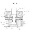
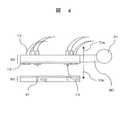
細胞の播種や培地の交換の様子を、図1ないし図5を用いて説明する。図1は、培養容器60と継ぎ手50を一体化した播種装置70をターンテーブル96上に取り付ける様子を示した斜視図である。図2は、図1に示した播種装置70の分解斜視図である。図3は、播種装置70の部分詳細断面図である。播種装置70は、中央部に培養空間42bが形成された容器部材40を有する培養容器60と、培養容器60の上部に配置され、培養液を培養空間42bに導入および培養空間42bから排出するための継ぎ手50とを備えている。 The state of cell seeding and medium exchange will be described with reference to FIGS. FIG. 1 is a perspective view showing a state in which a
容器部材40は厚みの薄い直方体状をしており、中央部に円形の中空部である培養空間41bが形成されている。容器部材40の底面には、膜42aが接着等で取り付けられている。容器部材40の円形空間部の周りには、4個の止まり穴41が形成されている。止まり穴41の底部近傍には、培養空間42bとこの止まり穴41を連通する流路43が形成されている。 The
容器部材40に形成した止まり穴41に対応する位置に弁31が形成された矩形状の第1の弾性シール30を、容器部材40の上面に接着等により保持する。第1の弾性シールは、シリコーン樹脂のような粘弾性部材で作られており、弁31はこの粘弾性部材に形成した十字型の切り込みである。容器部材40と第1の弾性シール30は、培養容器60を形成する。 The rectangular first
継ぎ手50は、培養容器60の上面に配置される矩形状の第2の弾性シール20と、この第2の弾性シール20が接着等で固定され厚みの薄い直方体状に形成された継ぎ手部材10とを有している。第2の弾性シール20は、シリコーン樹脂のような粘弾性部材で作られている。第2の弾性シール20は、容器部材40に形成した止まり穴41に対応する位置であって第1の弾性シール30に対向する位置に、リング状の微細突起21が形成されている。第2の弾性シール20の角部には、詳細を後述する吸引パッド用の孔22が形成されている。 The joint 50 includes a rectangular second
継ぎ手部材10は、厚みの薄い直方体状に形成されており、4角部であって底面には、第2の弾性シール20に形成した吸引パッド用の孔22に対応する位置に、ラッパ形状の吸着パッド15が取り付けられている。継ぎ手部材10の底面には、容器部材40の止まり穴41に嵌合するチューブ13を取り付ける貫通孔が形成されている。図3に示すように、この孔は段付き孔であり、上部の孔は、嵌合するコネクタ11を取り付けるために、ねじ孔になっている。 The
コネクタ11には、細胞懸濁液や培地、薬品を供給可能なチューブ12が着脱自在に接続される。継ぎ手部材10には、吸着パッド15の背面側に連通する孔も形成されており、この孔には吸引用チューブ14が嵌合されている。さらに、継ぎ手部材10の一方の側面には、アーム80が取り付けられている。 A
継ぎ手50と培養容器60とは、吸引用チューブ14から吸引して一体化され、播種装置70を構成する。一体化された播種装置70は、ベース95に形成した突起91と培養容器60の下部の周囲部に形成した溝90とを係合することにより、ベース95に固定される。 The joint 50 and the
このように構成した播種装置70を用いた培養方法を、以下に説明する。初めに図3を用いて、培養容器60を継ぎ手50に吸着させるときの様子を説明する。培養容器部材40にはチューブ13用の孔41が形成されているから、培養容器部材40を開放したままハンドリングすると、外からの菌等により汚染されるおそれがある。また、孔41からの液漏れにより、環境を汚染するおそれもある。また、新しいチューブ13を培地交換の度に容器部材40に形成した孔41に挿入して汚染を防いでいるが、その結果、チューブ13の交換頻度が高くなる。したがって、交換頻度が高くなっても、チューブ13と孔41間が確実にシールされるとともに、チューブ13を取り外しても孔41からの漏れが生じないように、孔41を自動的に閉じる必要がある。そこで、培養容器60内が汚染されるのを防止するために、次のようなシールを用いている。 A culture method using the seeding
すなわち、培養容器60と継ぎ手50の着脱時における密着性と液漏れ防止性を向上させるために、第2の弾性シール20を継ぎ手部材10の底面側に、第1の弾性シール30を培養容器部材40の上面側にそれぞれ接着する。そして、第2の弾性シール20に第1の弾性シール30を吸引ポンプを用いて密着させた。第2の弾性シール20と第1の弾性シール30の密着性を向上させるために、これらの弾性シール20、30に、粘弾性部材を使用した。 That is, in order to improve adhesion and liquid leakage prevention properties when the
孔41からの菌等の混入や液漏れを防止するとともに、チューブ13が孔41に挿入されていないときには、孔41を自動的に閉じるフタの代わりに、第1の弾性シール30にスリット31aからなる弁31を形成している。チューブ13挿入時にスリット31a部から下方に押し出されていたシール片31bが、チューブ13が孔41に挿入されていないときは弾性力により復元して、弁31は閉じた状態を維持する。その結果、液漏れが防止される。 In addition to preventing bacteria and the like from leaking from the
培養のために、チューブ13をスリットに挿入すると、シール片31bが下方に押し広げられ、弁31は開かれる。弁31を構成するシール片31bは弾性力により、チューブ13に密着するので、液の漏れや逆流が防止される。なお、弁31には液漏れと汚染防止のために、撥水処理を施している。 When the
一方、第2の弾性シール20のチューブ13用の孔の周辺に、環状の微細突起21を設けて、第1の弾性シール30と第2の弾性シール20との吸着に用いる。継ぎ手50と培養容器60とを吸着させるときには、図4に詳細を示す吸着パッド15を用いて、真空吸引する。吸着パッド15は、吸引チューブ14を介して図示しない吸引ポンプに接続されている。吸引の際には、微細突起21を培養容器60に押し付けて、孔41周辺に形成したシール部の密着性を高めている。 On the other hand, an annular
第2の弾性シール20に微細突起21を形成したので第1の弾性シール30と第2の弾性シール20との接触面積が低減し、接触部の面圧が増大する。これに対して、微細突起21がないと、第1の弾性シール30と第2の弾性シール20との面圧が低下し、チューブ13周辺におけるシール性が低下する。 Since the
また、微細突起21を設けたので、培養容器60を継ぎ手50から外すのが容易になる。第1、第2の弾性シール30、20は、ともに粘弾性部材であるから密着性がよい。そこで、環状の微細突起21であるシール部以外の部分が、不用意に培養容器60に密着するのを微細突起21の段差が防止する。この微細突起21の形成により、継ぎ手50と培養容器60間の液漏れが防止されるとともに、継ぎ手50を外した時に液がチューブ13近傍に残って周囲を汚染するのが防止される。さらに、微細突起21に撥水処理を施しているので、微細突起21に培地が付着することはない。 Further, since the
次に、図4および図5、図7を用いて、培養容器60に細胞懸濁液や培地を注液する方法を説明する。図4は、播種装置70の正面図である。水平に置かれた培養容器60の上方に継ぎ手50を配置する。継ぎ手50の側部に、アーム80が取り付けられており、アーム80の端部は回転軸81に接続されている。回転軸81は、上方向70aおよび下方向70bに移動可能である。 Next, a method for injecting a cell suspension or a medium into the
継ぎ手50を位置決めするときは、培養容器60に形成した孔41に継ぎ手50に取り付けたチューブ13を合わせる。図3に示すように、継ぎ手50に固定したチューブ13が、シール片31bを下方に押出して、培養容器60に形成した孔41にチューブ13が挿入される。培養容器60に継ぎ手50が載ったら、図示しない吸引ポンプを作動させ、吸引用チューブ14が接続された吸引パッド15が培養容器60を吸引して継ぎ手50に密着する。これにより第2の樹脂シール20と第1の樹脂シール30が密着する。 When positioning the joint 50, the
継ぎ手50と培養容器60が密着して一体型の播種装置70が形成されたら、回転軸81を用いて、一体型の播種装置70を傾斜させる。図5に、播種装置70の正面図を示す。回転軸81を時計周り81aに90度回転させる。密着した培養容器60と継ぎ手50を水平方向から垂直方向に回転70cさせる。 When the joint 50 and the
この状態で、培養空間42bに下方向に位置するチューブ12から、培地や細胞懸濁液を注液12bする。一方、上方向に位置するチューブ12から、播種装置60内の廃液や気体を排出12aする。注液する培地は、別の場所に冷蔵保管したものを用い、使用直前に適温に温めて新鮮な培地として図示しないポンプで培養空間42bに供給する。播種装置60を垂直方向に立てて、注液および排液作業するので、培養空間42bに混入した気泡を抜くことができる。 In this state, a medium or a cell suspension is injected 12b from the
所定の液を注液し終えたら、回転軸81を反時計周り81bに回転させる。一体化した播種装置70を、垂直方向から水平方向70dに戻す。上下方向に移動可能な回転軸81を操作して、図1に示したベース95に播種装置60をセッテングする。播種装置60の側面には、溝90に係合する突起91が形成されているので、播種装置70を予め定められた係止前の位置に位置決めする。その後、水平方向92aに播種装置70を移動させて突起91を溝90に係止する。 When the predetermined liquid has been injected, the rotating
吸着パッド15からの吸引を停止するために、吸引ポンプを止める。その後、吸着パッド15に圧力空気を供給する。圧力空気が送風されると、培養容器60と継ぎ手50間の吸引力の代わりに反発力が発生し、培養容器60と継ぎ手50間の密着力が失われる。培養容器60と継ぎ手50間の密着力が失われたので、上下方向70a、70bに移動可能な回転軸80を、上方向70aに操作して、播種装置60と継ぎ手50を離す。 In order to stop the suction from the
培養容器60を持ち上げる70aときは、回転軸80を下方向70bに操作し、継ぎ手50と培養容器60を吸着して密着させる。その後、図1に示すように突起91と溝90の係合を外す方向92bに、播種装置70を移動させる。溝90と突起91との係合が外れたら、播種装置70を上方向70aに移動して、注液する。この一連の作業手順により、培養容器60に細胞懸濁液や培地を入れるときであっても、培養空間42bを限りなく閉鎖系の状況に保つことができる。これにより、培養空間42b等からの漏れや汚染が防止される。 When the
図7に、この一連の動作で使用する継ぎ手保持位置決め部111を、斜視図で示す。前後方向111a、111bにスタンド120が移動可能なように、移動方向に沿ってレール121が取り付けられている。スタンド120は基部でレール121に嵌合している。スタンド120の上下方向に延びる軸122には、上下方向70a、70bに移動可能なギア軸123が取り付けられている。ギア軸123にはラック124が噛み合っており、ギア軸123を回転させると、ラック124が左右方向92a、92bに進退する。ラック124の先端には、回転軸81が水平方向であってレールと同じ向きに取り付けられている。回転軸81には、播種装置70のアーム80が取り付け可能になっている。回転軸81を回転させると、播種装置70は前後方向111a、111bに延びる回転軸81周りに回転81a、81bする。 FIG. 7 is a perspective view showing the joint holding and
10…継ぎ手部材、12…チューブ、12a…排気、廃液、12b…注液、13…チューブ、14…吸引用チューブ、15…吸着パッド、20…第2の弾性シール、21…微細突起、22…吸引パット用孔、30…第1の弾性シール、31…弁、40…培養容器部材、41…孔、42a…ガス透過膜、42b…培養空間、43…流路、50…継ぎ手、60…培養容器、70…播種装置、70a…継ぎ手移動上方向、70b…継ぎ手移動下方向、70c…右回転方向、70d…左回転方向、80…アーム、81…回転軸、81a…右回転方向、81b…左回転方向、90…溝、91…突起、92a…水平移動方向(非固定)、92b…水平移動方向(固定)、95…ベース、96…ターンテーブル、110…培養装置、111…継ぎ手保持位置決め部、111a…移動方向(前)、111b…移動方向(後)、112…培養容器投入口部、113…培養室、114…細胞投入部、115…培地供給部。DESCRIPTION OF
Claims (4)
Translated fromJapanese部に配置された第1の弾性シールとを有する培養容器と、この培養容器に培地等の溶液を
供給する供給手段が設けられた継ぎ手部材とこの継ぎ手部材に接着された第2の弾性シー
ルとを有する継ぎ手とを備え、前記継ぎ手に形成した吸引手段を用いて前記培養容器を前
記継ぎ手に着脱可能としたことを特徴とする培養装置。A culture container having a culture container member in which a culture space for culturing cells is formed, a first elastic seal disposed above the culture space of the culture container member, and supplying a solution such as a medium to the culture container A coupling member having a coupling member provided with a supply means and a second elastic seal bonded to the coupling member, wherein the culture vessel can be attached to and detached from the coupling using suction means formed on the coupling. A culture apparatus characterized by that.
し吸引力を作動させるポンプとを有することを特徴とする請求項1に記載の培養装置。The culture apparatus according to claim 1, wherein the suction means includes a suction member attached to the second elastic seal and a pump that communicates with the suction member and operates a suction force.
地等の溶液を供給する供給部が形成され、下面に微細突起を有する第2の弾性シール部材
を接着した継ぎ手とを備え、前記第1の弾性シールは溶液を供給または排出するための弁
を有し、前記第2の弾性シールは前記弁に対応した位置に漏れを防止する微細突起が形成
されており、前記培養容器と前記継ぎ手とを吸引して、第1の弾性シールと第2の弾性シ
ールを密着させて一体化した播種装置を形成したことを特徴とする培養装置。A culture vessel in which a first elastic seal is bonded to the upper surface to form a culture space, and a supply unit for supplying a solution such as a medium to the culture vessel is formed, and a second elastic seal member having fine protrusions on the lower surface is formed. The first elastic seal has a valve for supplying or discharging a solution, and the second elastic seal is formed with a fine protrusion for preventing leakage at a position corresponding to the valve. The culture device is characterized in that the culture vessel and the joint are sucked to form a seeding device in which the first elastic seal and the second elastic seal are brought into close contact with each other.
培養装置。4. The culture apparatus according to claim 3, wherein the valve and the surface of the fine protrusion are subjected to a water repellent treatment.
Priority Applications (3)
| Application Number | Priority Date | Filing Date | Title |
|---|---|---|---|
| JP2004341399AJP4563782B2 (en) | 2004-11-26 | 2004-11-26 | Incubator |
| US11/192,023US7749750B2 (en) | 2004-11-26 | 2005-07-29 | Culturing apparatus |
| US12/817,333US8652834B2 (en) | 2004-11-26 | 2010-06-17 | Culturing apparatus |
Applications Claiming Priority (1)
| Application Number | Priority Date | Filing Date | Title |
|---|---|---|---|
| JP2004341399AJP4563782B2 (en) | 2004-11-26 | 2004-11-26 | Incubator |
Related Child Applications (1)
| Application Number | Title | Priority Date | Filing Date |
|---|---|---|---|
| JP2010156450ADivisionJP5161929B2 (en) | 2010-07-09 | 2010-07-09 | Incubator |
Publications (3)
| Publication Number | Publication Date |
|---|---|
| JP2006149237A JP2006149237A (en) | 2006-06-15 |
| JP2006149237A5 JP2006149237A5 (en) | 2007-06-28 |
| JP4563782B2true JP4563782B2 (en) | 2010-10-13 |
Family
ID=36567846
Family Applications (1)
| Application Number | Title | Priority Date | Filing Date |
|---|---|---|---|
| JP2004341399AExpired - Fee RelatedJP4563782B2 (en) | 2004-11-26 | 2004-11-26 | Incubator |
Country Status (2)
| Country | Link |
|---|---|
| US (2) | US7749750B2 (en) |
| JP (1) | JP4563782B2 (en) |
Families Citing this family (28)
| Publication number | Priority date | Publication date | Assignee | Title |
|---|---|---|---|---|
| JP4953769B2 (en)* | 2006-11-02 | 2012-06-13 | 三洋電機株式会社 | Cell culture device and cell culture cassette |
| JP4403169B2 (en) | 2006-12-15 | 2010-01-20 | 株式会社日立製作所 | Cell culture apparatus and control method thereof |
| JP4445993B2 (en)* | 2007-11-27 | 2010-04-07 | 株式会社日立製作所 | Cell culture equipment |
| JP4845950B2 (en)* | 2008-10-30 | 2011-12-28 | 株式会社日立製作所 | Automatic culture equipment |
| JP2010207174A (en)* | 2009-03-12 | 2010-09-24 | Atto Corp | Perfusion cultivation system |
| JP4602460B1 (en)* | 2009-07-02 | 2010-12-22 | 株式会社日立製作所 | Cell culture vessel |
| JP4824102B2 (en)* | 2009-07-13 | 2011-11-30 | 株式会社日立製作所 | Cell culture equipment |
| JP4903252B2 (en)* | 2009-11-30 | 2012-03-28 | 株式会社日立製作所 | Cell culture equipment |
| JP5140095B2 (en)* | 2010-01-13 | 2013-02-06 | 株式会社日立製作所 | Automatic culture apparatus and culture container installation method |
| CN102985526A (en) | 2010-07-16 | 2013-03-20 | 株式会社日立制作所 | Cell culture vessel and cell culture device |
| US20130143307A1 (en) | 2010-08-12 | 2013-06-06 | Takayuki Nozaki | Automatic culture device |
| CN105154329A (en)* | 2010-08-12 | 2015-12-16 | 株式会社日立制作所 | Automatic culture apparatus |
| JP2014502144A (en) | 2010-10-06 | 2014-01-30 | ビーピー・コーポレーション・ノース・アメリカ・インコーポレーテッド | Variant CBHI polypeptide |
| JP5167375B2 (en)* | 2011-02-14 | 2013-03-21 | 株式会社日立製作所 | Cell culture apparatus and control method thereof |
| US20140141499A1 (en) | 2011-06-27 | 2014-05-22 | Hitachi, Ltd. | Cell Culture Device and Cell Culture Method |
| EP2832847B1 (en) | 2012-03-29 | 2019-02-06 | Hitachi, Ltd. | Culture vessel and automated culture apparatus |
| JP5694277B2 (en)* | 2012-11-16 | 2015-04-01 | 株式会社日立製作所 | Automatic culture equipment |
| JP6134816B2 (en)* | 2014-01-27 | 2017-05-24 | 株式会社日立ハイテクノロジーズ | Cell culture equipment |
| JP6189787B2 (en)* | 2014-04-28 | 2017-08-30 | 豊田合成株式会社 | Cell culture equipment |
| CN107075442A (en)* | 2014-11-07 | 2017-08-18 | 株式会社日立高新技术 | Aseptic connector and cell culture device with the same |
| JP5886455B2 (en)* | 2015-03-25 | 2016-03-16 | 株式会社日立製作所 | Automatic culture equipment |
| EP3313434B1 (en) | 2015-06-29 | 2025-04-02 | Northeastern University | Dendritic cell generator |
| CN105176815B (en)* | 2015-10-20 | 2017-03-22 | 哈尔滨工业大学 | Gas-liquid interface perfusion bioreactor for artificial skin tissue culture and preparation method and application method of gas-liquid interface perfusion bioreactor |
| JP6995369B2 (en)* | 2015-11-18 | 2022-01-14 | スライブ バイオサイエンス, インコーポレイテッド | Instrument resource scheduling |
| US10647954B1 (en)* | 2018-11-15 | 2020-05-12 | Flaskworks, Llc | Dendritic cell generating apparatus and method |
| US11566217B2 (en) | 2019-08-13 | 2023-01-31 | Flaskworks, Llc | Duty cycle for cell culture systems |
| WO2021080847A1 (en) | 2019-10-21 | 2021-04-29 | Flaskworks, Llc | Systems and methods for cell culturing |
| JP2025059305A (en)* | 2023-09-29 | 2025-04-10 | Zacros株式会社 | Lid, cell culture device or bioreactor vessel, and cell culture device |
Family Cites Families (16)
| Publication number | Priority date | Publication date | Assignee | Title |
|---|---|---|---|---|
| US4228243A (en)* | 1978-07-13 | 1980-10-14 | Toray Industries, Inc. | Cell culture propagation apparatus |
| JPS60177800U (en)* | 1984-05-08 | 1985-11-26 | 日東電工株式会社 | Sterile inoculation device |
| US4661455A (en)* | 1986-01-16 | 1987-04-28 | Dorr-Oliver Incorporated | Membrane cell culturing device |
| US4839292B1 (en)* | 1987-09-11 | 1994-09-13 | Joseph G Cremonese | Cell culture flask utilizing membrane barrier |
| US5153131A (en)* | 1990-12-11 | 1992-10-06 | The United States Of America As Represented By The Administrator Of The National Aeronautics And Space Administration | High aspect reactor vessel and method of use |
| US6284113B1 (en)* | 1997-09-19 | 2001-09-04 | Aclara Biosciences, Inc. | Apparatus and method for transferring liquids |
| US6455310B1 (en)* | 1999-03-23 | 2002-09-24 | Biocrystal Ltd. | Cell culture apparatus and method for culturing cells |
| JP2002262856A (en) | 2001-03-07 | 2002-09-17 | Japan Tissue Engineering:Kk | Automatic medium exchange method, program and automatic medium exchange apparatus |
| CN100418632C (en)* | 2001-05-30 | 2008-09-17 | 比奥莱克斯公司 | Plates and methods for high-throughput screening |
| US6673595B2 (en)* | 2001-08-27 | 2004-01-06 | Biocrystal, Ltd | Automated cell management system for growth and manipulation of cultured cells |
| JP2004129568A (en) | 2002-10-10 | 2004-04-30 | Olympus Corp | Culture vessel and culturing method |
| US7725161B2 (en)* | 2003-02-03 | 2010-05-25 | John Hopkins University | Active MRI intramyocardial injeciton catheter with a deflectable distal section |
| JP2004236514A (en) | 2003-02-04 | 2004-08-26 | Hitachi Ltd | Culture device |
| US20040241835A1 (en)* | 2003-02-06 | 2004-12-02 | Hutmacher Dietmar W. | Dual axis bioreactor, system and method for growing cell or tissue cultures |
| US7604987B2 (en)* | 2003-02-06 | 2009-10-20 | National University Of Singapore | Bioreactor for growing cell or tissue cultures |
| JP4454953B2 (en)* | 2003-03-31 | 2010-04-21 | キヤノン株式会社 | Biochemical reaction cartridge |
- 2004
- 2004-11-26JPJP2004341399Apatent/JP4563782B2/ennot_activeExpired - Fee Related
- 2005
- 2005-07-29USUS11/192,023patent/US7749750B2/ennot_activeExpired - Fee Related
- 2010
- 2010-06-17USUS12/817,333patent/US8652834B2/ennot_activeExpired - Fee Related
Also Published As
| Publication number | Publication date |
|---|---|
| US7749750B2 (en) | 2010-07-06 |
| JP2006149237A (en) | 2006-06-15 |
| US20100255568A1 (en) | 2010-10-07 |
| US8652834B2 (en) | 2014-02-18 |
| US20060115893A1 (en) | 2006-06-01 |
Similar Documents
| Publication | Publication Date | Title |
|---|---|---|
| JP4563782B2 (en) | Incubator | |
| JP4403169B2 (en) | Cell culture apparatus and control method thereof | |
| KR101589356B1 (en) | Cell culture device and transport device | |
| JP5722329B2 (en) | Automatic culture equipment | |
| US10139322B2 (en) | Sample preparation device | |
| JP6854767B2 (en) | Switching valve and suction / discharge device equipped with this | |
| JP5055479B2 (en) | Automatic cell culture equipment | |
| WO2012098931A1 (en) | Cell culture treatment system, and method for connection of modules for cell culture treatment system | |
| JP5140095B2 (en) | Automatic culture apparatus and culture container installation method | |
| JP2001031127A (en) | Cap | |
| JP2004016194A (en) | Cell culture apparatus | |
| JP2013128458A (en) | Packaging container | |
| EP2478920B1 (en) | Sterilized connection apparatus | |
| JP5161929B2 (en) | Incubator | |
| JP2012217435A (en) | Cell culture device | |
| JP2013031461A (en) | Automated culturing apparatus | |
| JP5068942B2 (en) | Vacuum dispensing device | |
| US20150217294A1 (en) | Sealed container and cell transfer system | |
| JP5101819B2 (en) | Cell culture equipment | |
| JP4824102B2 (en) | Cell culture equipment | |
| JP5886455B2 (en) | Automatic culture equipment | |
| JP2006141265A (en) | Cover for culture container, culture container and apparatus for culture treatment | |
| TWI862667B (en) | Cell treatment system | |
| JP7366935B2 (en) | Drive mechanism compatible with gas sterilization | |
| JP2008048644A (en) | Culture instrument and culture apparatus |
Legal Events
| Date | Code | Title | Description |
|---|---|---|---|
| RD04 | Notification of resignation of power of attorney | Free format text:JAPANESE INTERMEDIATE CODE: A7424 Effective date:20060425 | |
| A521 | Request for written amendment filed | Free format text:JAPANESE INTERMEDIATE CODE: A523 Effective date:20070515 | |
| A621 | Written request for application examination | Free format text:JAPANESE INTERMEDIATE CODE: A621 Effective date:20070515 | |
| RD02 | Notification of acceptance of power of attorney | Free format text:JAPANESE INTERMEDIATE CODE: A7422 Effective date:20070615 | |
| RD04 | Notification of resignation of power of attorney | Free format text:JAPANESE INTERMEDIATE CODE: A7424 Effective date:20070919 | |
| A977 | Report on retrieval | Free format text:JAPANESE INTERMEDIATE CODE: A971007 Effective date:20090930 | |
| A131 | Notification of reasons for refusal | Free format text:JAPANESE INTERMEDIATE CODE: A131 Effective date:20100511 | |
| A521 | Request for written amendment filed | Free format text:JAPANESE INTERMEDIATE CODE: A523 Effective date:20100709 | |
| TRDD | Decision of grant or rejection written | ||
| A01 | Written decision to grant a patent or to grant a registration (utility model) | Free format text:JAPANESE INTERMEDIATE CODE: A01 Effective date:20100727 | |
| A01 | Written decision to grant a patent or to grant a registration (utility model) | Free format text:JAPANESE INTERMEDIATE CODE: A01 | |
| A61 | First payment of annual fees (during grant procedure) | Free format text:JAPANESE INTERMEDIATE CODE: A61 Effective date:20100729 | |
| FPAY | Renewal fee payment (event date is renewal date of database) | Free format text:PAYMENT UNTIL: 20130806 Year of fee payment:3 | |
| R150 | Certificate of patent or registration of utility model | Free format text:JAPANESE INTERMEDIATE CODE: R150 | |
| LAPS | Cancellation because of no payment of annual fees |