JP4563630B2 - Dental instruments and dental wedge instruments - Google Patents
Dental instruments and dental wedge instrumentsDownload PDFInfo
- Publication number
- JP4563630B2 JP4563630B2JP2001387419AJP2001387419AJP4563630B2JP 4563630 B2JP4563630 B2JP 4563630B2JP 2001387419 AJP2001387419 AJP 2001387419AJP 2001387419 AJP2001387419 AJP 2001387419AJP 4563630 B2JP4563630 B2JP 4563630B2
- Authority
- JP
- Japan
- Prior art keywords
- dental wedge
- dental
- handle
- wedge
- instrument
- Prior art date
- Legal status (The legal status is an assumption and is not a legal conclusion. Google has not performed a legal analysis and makes no representation as to the accuracy of the status listed.)
- Expired - Lifetime
Links
Images


Classifications
- A—HUMAN NECESSITIES
- A61—MEDICAL OR VETERINARY SCIENCE; HYGIENE
- A61C—DENTISTRY; APPARATUS OR METHODS FOR ORAL OR DENTAL HYGIENE
- A61C5/00—Filling or capping teeth
- A61C5/80—Dental aids fixed to teeth during treatment, e.g. tooth clamps
- A61C5/88—Wedges
Landscapes
- Health & Medical Sciences (AREA)
- Oral & Maxillofacial Surgery (AREA)
- Dentistry (AREA)
- Epidemiology (AREA)
- Life Sciences & Earth Sciences (AREA)
- Animal Behavior & Ethology (AREA)
- General Health & Medical Sciences (AREA)
- Public Health (AREA)
- Veterinary Medicine (AREA)
- Dental Tools And Instruments Or Auxiliary Dental Instruments (AREA)
- Dental Prosthetics (AREA)
Description
Translated fromJapanese(技術分野)
本発明は広範には、歯科ウェッジに関し、より詳細には、歯間に配置しやすいハンドル付きの歯科ウェッジに関する。
【0001】
(背景技術)
多くの歯科治療において、特に充てん歯科治療において、しばしば歯科ウェッジが必要となる。2つの歯の間が虫歯になっているとき、その歯間で歯科材料を取り除かなければならないことがよくある。充てんの準備段階として歯科材料を取り除いたあと、マトリックスバンドをその歯間に配置して、壁を形成し、充てん用歯科材料をそこに保有することがしばしば行われる。しかしマトリックスバンドの多くは、充てんされる場所が歯の下端部や歯肉部分である場合は、うまく適合しない。マトリックスバンドが、歯によくフィットするように、そして歯肉部分にも適合できるように、マトリックスバンドとそれに隣接する歯との間の領域に、ウェッジを押し込むことがしばしば行われる。ウェッジの目的は、マトリックスバンドの歯肉対応部を歯に押しつけて、充てん材料が窩洞形成分以上に押し込まれないようにすることである。窩洞形成分以上に充てん材料があると、それがあたって刺激が続いたり、歯槽膿漏を起こしたりする場合がある。またウェッジは、マトリックスバンドの厚みを受け入れるために歯間を押し広げる助けにもなっている。充てん材料の配置後、マトリックスバンドとウェッジを取り出して、それと共に歯の間のわずかな分離もつめることができる。ウェッジの材料は普通、比較的小さな木材片やプラスチック片である。さらにウェッジは、多くの異なる形状をとる。ウェッジはそれだけでは扱いにくいので、隣接する歯とマトリックスバンドとの間に押し込むのに、鉗子やピンセット状の器具を用いてつまみ上げなければならない。そしてこれらの小さなウェッジは、歯科診療室にあるような従来の器具を使って、つかんだり、動かしたりするのは難しい。さらにもっと大きい歯科器具を用いると、治療部位を見にくくして、歯科ウェッジの配置を困難にしてしまう。そこで歯科医学において、配置しやすく、歯間に位置づけしやすい、歯科ウェッジが必要となっている。
【0002】
(発明の開示)
本発明は、屈曲可能で折れやすい状態のハンドル付きの歯科ウェッジである。所定の形状と断面積を有する歯科ウェッジを、ハンドルの一方の端部に取付けている。ネックとなる折れやすい部分が、歯科ウェッジとハンドルとの間に位置づけられている。ハンドルは、配置するのに好都合な程度にはしっかりと歯科ウェッジ部分に取付けられており、一方で、歯科ウェッジ部分から取り外そうと思えば容易に取り外せるようにもなっている。1つの実施形態においては、屈曲性部分がハンドルに含まれて、歯科ウェッジをよりよく配置するような角度づけを行えるようになっている。他の実施形態のそれぞれにおいては、これらとは異なる歯科ウェッジが用いられている。
【0003】
したがって本発明の目的は、歯科ウェッジの容易な配置を提供することである。
本発明の別の目的は、歯科ウェッジの使用中に、汚染物が交雑する恐れを減らす、あるいはなくすことである。
【0004】
本発明の利点は、安価で製造でき、1回ごとに使い捨てできることである。
本発明の別の利点は、鉗子、プライヤー、ピンセットのような他の用具なしに、歯科ウェッジ部分を歯間に配せるまたは配置できることである。
本発明の特徴は、ハンドル部分がウェッジ部分に取付けられていることである。
【0005】
本発明の別の特徴は、ハンドル部分がウェッジ部分に折れやすい状態で取付けられていることである。
本発明のさらに別の特徴は、ハンドルの一部分が屈曲可能でウェッジを配置しやすくなっていることである。
【0006】
本発明のこれらおよび他の目的、利点、および特徴は、以下のより詳細な説明によって、容易に明らかになるであろう。
【0007】
【発明の実施の形態】
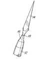
図1は、本発明の実施形態である、折れやすいハンドル付きの歯科ウェッジ10である。ハンドル部分12が歯科ウェッジ部分14に取付けられている。歯科ウェッジ部分14は、ウェッジングに適切な望ましい形状であれば特に限定されない。径方向の寸法、すなわち径が小さくなっているネック部分16が、歯科ウェッジ部分14とハンドル部分12との間に配されている。ハンドル付きの歯科ウェッジ10の材料としては、適切なものであれば特に限定されず、たとえば、プラスチックや木材でよい。ハンドル付き歯科ウェッジ10が1種類の適切なプラスチックからできていると好ましい。折れやすい部分18があることによって、歯科ウェッジ部分14とハンドル部分12とを容易に分離できる。ハンドル部分12は、歯科ウェッジ部分14より実質的に長いと好ましい。ハンドル部分12は歯科ウェッジ部分14の長さに対して、その4倍にもなる長さである。たとえば歯科ウェッジ部分14の長さがおよそ0.5インチ、すなわちおよそ1.3センチメートル、もしくはそれ以上で、ハンドル部分12の長さがおよそ4.0インチ、すなわちおよそ6.2センチメートル、もしくはそれ以上となる。ハンドル部分12の実質的な長さによって、歯科ウェッジ部分14の把持や配置が容易になっている。
【0008】
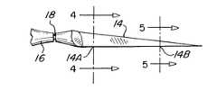
図2は、図1の状態から長手方向の軸沿いに、わずかに回転させた本発明の一部分を示している。歯科ウェッジ部分14の平面部が、図2ではより明確に示されている。
図3は、歯科ウェッジ部分14の長手方向の長さ沿いに異なる点を示したものである。歯科ウェッジ部分14の径方向の寸法は、位置14Aのほうが位置14Bより大きい。
【0009】
図4は、図3に示された線4−4に沿った位置14Aにおける断面を示したものである。この断面は、一般的には三角形であり、正三角形でも二等辺三角形でもよい。しかし、他の形状や他の三角形の断面であってもよい。
図5は、図3に示された線5−5に沿った位置14Bにおける断面を示したものである。位置14Bでの断面もまた、実質的に三角形である。ただし、位置14Bでの径方向の寸法は、図3に示された位置14Aにおけるものより、小さくなっている。したがって、歯科ウェッジ部分14の頂点すなわち先端を歯間に挿入すれば、この歯科ウェッジ部分は、歯と歯あるいは他の当接面を分離させる、または圧をかけるウェッジとして、機能する。
【0010】
図6は、本発明の作用と、充てん歯科治療における適用とを示したものである。2本の歯、20と21とが互いに隣接しあってギャップを形成している。そしてそれらの歯間に、歯科ウェッジ部分14を挿入する。歯21にはその内部に窩洞24が形成されており、この窩洞24は、歯科充てん材料で充てんされることになっている。さらに歯21は、これに隣接して配されたマトリックスバンド22を有する。マトリックスバンド22は、壁を形成して、歯科充てん材料をその中に含有する。マトリックスバンドは普通、歯21の全体を取り囲むが、解りやすく示すために、その一部分だけを示している。歯科ウェッジ部分14は、ハンドル部分12を使って歯20と歯21との間に、矢印26の方向で挿入する。歯科ウェッジ部分14の一方の側もしくは一方の面が歯20に当接し、歯科ウェッジ部分14の他方の側もしくは他方の面がマトリックスバンド22に当接する。このようにして、マトリックスバンド22は、歯21の歯茎に隣接して確実に配置される。歯科ウェッジ部分14の配置後、ハンドル部分12はそのままの位置でよく、あるいは、ハンドル部分12を矢印28の方向で前後に振る、または動かすことによって取り外して、別に追加される処置域のために用いても良い。ハンドル部分12は、矢印30の方向でも回転できる。振ること、回転すること、回すこと、ねじること、あるいはそれらの組合わせにより、折れやすい部分18が折れる。その結果、ハンドル部分12とウェッジ部分14とが分離するようになる。
【0011】
図7は、ハンドル部分が歯科ウェッジ部分14から分離した後の、歯20と歯21との間に残っている歯科ウェッジ部分14を示したものである。窩洞24が形成されており、それは歯科充てん剤で充てんされる。ハンドル部分を取り外して、処置域を他に、追加してもよい。
【0012】
図8は、歯科ウェッジ部分14の歯21の歯茎への配置を示す側面図である。この配置により、マトリックスバンド22は歯21の歯茎の形状に密に沿って保持される。それによって、形成されていた窩洞24内に歯科充てん材を充てんできるようになる。
【0013】
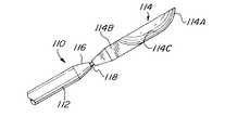
図9は、本発明の別の実施形態を示している。この実施形態において、ハンドル付きの歯科ウェッジ110は、ハンドル部分112と歯科ウェッジ部分114とを有する。歯科ウェッジ部分114とハンドル部分112とは、ネック部分116で、分離する。つまり折れやすい部分118がネック部分116内に形成されている。そして、この折れやすい部分118の径方向の寸法が、ネック部分116のものより小さくなっている。あるいは、ネック部分116が、ネック部分より径の小さい折れやすい部分118が不要なほど、折れやすくなっていてもよい。歯科ウェッジ部分114は、曲線状の前部114Aと直線状の後部114Bとを有する。面114Cすなわち角度付けされた側面が、ウェッジ機能を果たす。このような形状はウェッジとしてより解剖学的である。
【0014】
図10は、歯科ウェッジ部分114を示す正面図である。曲線状の前部114Aと直線状の後部114Bとがさらに明確に示されている。
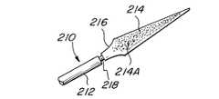
図11は本発明のハンドル付きの歯科ウェッジ210のさらに別の実施形態を示している。この実施形態では、ハンドル部分212が、歯科ウェッジ部分214に、折れやすい部分218によって取付けられている。ネック部分216が、歯科ウェッジ部分214と折れやすい部分218との間の移行部を提供している。歯科ウェッジ部分214は、三角形の断面で3辺または3面を有していても良い。各辺または各面が織り目模様が入った表面214Aを有して、歯と歯との間やマトリックスバンドを把持しやすいようになっている。織り目模様が入った表面214Aは、凹凸のある表面でもよいし、凹部ができていてもよいし、あるいは他の掴み面になっていてもよい。
【0015】
図12は、本発明のまた別の実施形態、ハンドル付きの歯科ウェッジ310を示している。ハンドル部分312は、歯科ウェッジ部分314に隣接して配されており、折れやすい部分318によって分離される。歯科ウェッジ部分314は一般的には、三角形の断面でリブ314Aのついた3辺または3面を有していてよい。これらのリブ314Aは、各辺または各面のそれぞれに横方向にわたって配されている。リブ314Aは、でっぱりとなって、あるいは凹みとなって、歯科ウェッジ部分314の面上に配されている。
【0016】
図13および14は、本発明のさらに別の実施形態、ハンドル付きの歯科ウェッジ410を示している。ただしこの実施形態では、屈曲手段または屈曲性部分413を用いる。ハンドル付きの歯科ウェッジ410は、ハンドル部分412と歯科ウェッジ部分414とを有する。歯科ウェッジ部分414に隣接するのが、折れやすい部分418である。そしてこの折れやすい部分418に隣接するのが、屈曲性部分413である。屈曲性部分413は、屈曲可能な部分でさえあれば、いずれの形状をとってもよい。ただしこの実施形態では、屈曲性部分は、複数の谷415と山417とを構成している。つまり、屈曲性部分413に沿って、径方向の寸法が交互に減少と増加を繰り返している。したがって、折れやすいハンドル付きの歯科ウェッジ410が、屈曲性部分413に沿って屈曲でき、歯科ウェッジ部分414の配置をしやすくしている。屈曲性部分は、ひだ付きなど、他の形状でもよい。さらに屈曲性部分は、これらと均等な他の形状でもよい。図14は、折れやすいハンドル付きの歯科ウェッジ410が屈曲性部分に沿って屈曲しているところを示している。この屈曲性部分によって、口裂の裏側のような届きにくい領域の歯間への、歯科ウェッジ部分414の配置が非常にしやすくなる。
【0017】
こうして本発明は、従来技術における歯科ウェッジと比べ、多くの利点を有する。ウェッジは比較的小さく、従来は、治療部位に配置する前に患者の口のなかで落としてしまうことがあったが、本発明ではそのようなことが減った。つまりハンドルを外す前に、ウェッジの配置が確実に行われている。ただしハンドルをそのままにしたい場合は、このハンドルで、ウェッジを取り外す、または再調整することも、容易である。歯科医や歯科技工士は、鉗子、ピンセット、あるいはプライヤーなどを用いた従来の歯科ウェッジ配置では技巧性が必要であったが、本発明ではそれほどの技巧性を必要とせずに、歯科ウェッジの配置が容易にできる。加えて本発明では、従来必要であった歯科ウェッジの配置に使用する器具の消毒が、不要となった。その結果、本発明では、汚染物交雑の恐れをなくした、あるいは実質的に減少させたのである。1つの実施形態において、ハンドルに屈曲性部分があることによって、オペレータは、折れやすいハンドル付きの歯科ウェッジを屈曲させることができ、その結果、ウェッジ部分の配置が都合よくできるようになった。ウェッジ部分が所望どおりの位置にきたら、圧をかけて、そのウェッジを歯間に挿入する。圧をかけてもそれ以上ウェッジの挿入が進まなくなったら、圧を取り除く。次いでハンドルを回転して、回して、ねじって、または屈曲させて、ウェッジ部分をハンドル部分から分離する。次いでハンドルを処分する。ウェッジ圧がさらに必要であれば、新たなハンドル付き歯科ウェッジを使用するか、ウェッジ部分を従来の手段を用いて再調整すればよい。歯科治療が完了後、歯科ウェッジは容易に取りだせる。本発明は、したがって、種々の歯科治療において歯科ウェッジの配置を極めて容易にした。
【0018】
以上、好適な実施形態を示して説明してきたが、当業者にとって、本発明の本質および範囲から外れることなく種々の変形が可能であることは、当然明らかであろう。
【図面の簡単な説明】
【図1】本発明の1つの実施形態を示したものである。
【図2】図1に示された実施形態の一部分について、それをわずかに回転させたものである。
【図3】本発明の歯科ウェッジ部分に沿って異なる点を略図的に示したものである。
【図4】図3の4−4線に沿って切断された断面図である。
【図5】図3の5−5線上に沿って切断された断面図である。
【図6】歯科充てんの準備の段階で、本発明における歯間への配置を略図的に示したものである。
【図7】本発明の歯科ウェッジ部分について、ハンドル部分を取り除いた後を、略図的に示したものである。
【図8】本発明の歯科ウェッジ部分の配置を示す側面図である。
【図9】異なる形状の歯科ウェッジ部分を有する、本発明の別の実施形態の一部分を示す側面図である。
【図10】図9に示された本発明の歯科ウェッジ部分の正面図である。
【図11】異なる歯科ウェッジ部分を有する本発明のさらに別の実施形態の一部を示す側面図である。
【図12】さらに異なる歯科ウェッジ部分を有する本発明のさらにまた別の実施形態の一部分を示す側面図である。
【図13】屈曲性部分を示す本発明の一部分の側面図である。
【図14】図13に示された実施形態の屈曲状態を示す側面図である。
【符号の説明】
10、110、210、310、410 ハンドル付き歯科ウェッジ
12、112、212、312、412 ハンドル部分
14、114、214、314、414 ウェッジ部分
14A、14B ウェッジ部分に沿った異なる点
16、216 ネック部分
18、218、318、418 折れやすい部分
20、21 歯
22 マトリックスバンド
24 窩洞
26、28 方向を表す矢印
114A ウェッジ部分の前部(曲線状)
114B ウェッジ部分の後部(直線状)
114C ウェッジ部分の角度付けされた側面
214A ウェッジ部分の織り目模様が入った表面(曲線状)
314A リブ
413 屈曲性部分
415 谷
417 山(Technical field)
The present invention relates generally to dental wedges, and more particularly to a dental wedge with a handle that is easy to place between teeth.
[0001]
(Background technology)
In many dental treatments, especially in filling dental treatments, a dental wedge is often required. When there is a decayed tooth between two teeth, it is often necessary to remove dental material between the teeth. Often, after the dental material is removed as a preparatory step for filling, a matrix band is placed between the teeth to form a wall and hold the filling dental material therein. However, many matrix bands do not fit well if the place to be filled is at the lower end of the tooth or the gingival part. It is often done to push the wedge into the area between the matrix band and the adjacent tooth so that the matrix band fits well with the teeth and can also fit into the gingival part. The purpose of the wedge is to press the gingival counterpart of the matrix band against the teeth so that the filling material is not pushed beyond the cavity formation. If there is more filling material than the cavity formation, it may cause irritation or alveolar pus leakage. The wedge also helps to spread the interdental space to accommodate the thickness of the matrix band. After placement of the filling material, the matrix band and the wedge can be removed and accompanied by a slight separation between the teeth. The wedge material is usually a relatively small piece of wood or plastic. Furthermore, the wedge takes many different shapes. Wedges are difficult to handle by themselves and must be picked up with forceps or tweezers to push between adjacent teeth and the matrix band. And these small wedges are difficult to grab and move using conventional instruments such as those found in dental clinics. Using even larger dental instruments makes it difficult to see the treatment site and makes it difficult to place the dental wedge. Therefore, in dental medicine, there is a need for a dental wedge that can be easily placed and positioned between teeth.
[0002]
(Disclosure of the Invention)
The present invention is a dental wedge with a handle that can be bent and bend easily. A dental wedge having a predetermined shape and cross-sectional area is attached to one end of the handle. A foldable portion that becomes a neck is positioned between the dental wedge and the handle. The handle is securely attached to the dental wedge portion to an extent convenient for placement, while being readily removable if it is intended to be removed from the dental wedge portion. In one embodiment, a bendable portion is included in the handle to allow angling to better place the dental wedge. Different dental wedges are used in each of the other embodiments.
[0003]
Accordingly, it is an object of the present invention to provide easy placement of dental wedges.
Another object of the present invention is to reduce or eliminate the risk of contamination contamination during use of the dental wedge.
[0004]
An advantage of the present invention is that it can be manufactured inexpensively and can be disposable once every time.
Another advantage of the present invention is that the dental wedge portion can be placed or placed between teeth without other tools such as forceps, pliers, tweezers.
A feature of the present invention is that the handle portion is attached to the wedge portion.
[0005]
Another feature of the present invention is that the handle portion is attached to the wedge portion in a fragile state.
Yet another feature of the present invention is that a portion of the handle is bendable to facilitate placement of the wedge.
[0006]
These and other objects, advantages and features of the present invention will be readily apparent from the following more detailed description.
[0007]
DETAILED DESCRIPTION OF THE INVENTION
FIG. 1 shows a
[0008]
FIG. 2 shows a portion of the present invention slightly rotated from the state of FIG. 1 along the longitudinal axis. The planar portion of the
FIG. 3 shows different points along the longitudinal length of the
[0009]
FIG. 4 shows a cross section at
FIG. 5 shows a cross-section at
[0010]
FIG. 6 shows the operation of the present invention and its application in filling dental treatment. Two teeth, 20 and 21, are adjacent to each other to form a gap. A
[0011]
FIG. 7 shows the
[0012]
FIG. 8 is a side view showing the placement of the
[0013]
FIG. 9 illustrates another embodiment of the present invention. In this embodiment, the
[0014]
FIG. 10 is a front view showing the
FIG. 11 shows yet another embodiment of a
[0015]
FIG. 12 shows another embodiment of the present invention, a
[0016]
FIGS. 13 and 14 show yet another embodiment of the present invention, a
[0017]
Thus, the present invention has many advantages over dental wedges in the prior art. Wedges are relatively small and have traditionally been dropped in the patient's mouth prior to placement at the treatment site, but this has been reduced in the present invention. In other words, the wedge is securely arranged before the handle is removed. However, when it is desired to leave the handle as it is, it is easy to remove or readjust the wedge with this handle. Dentists and dental technicians have needed skill in conventional dental wedge placement using forceps, tweezers, pliers, etc., but the present invention does not require much skill, and does not require much skill. Can be easily done. In addition, the present invention eliminates the need for disinfection of instruments used for placement of dental wedges, which has been conventionally required. As a result, the present invention eliminates or substantially reduces the risk of contamination. In one embodiment, the bendable portion of the handle allows the operator to bend a dental wedge with a foldable handle so that the placement of the wedge portion is convenient. When the wedge portion is in the desired position, pressure is applied and the wedge is inserted between the teeth. If the wedge does not advance any further when pressure is applied, remove the pressure. The handle is then rotated, turned, twisted, or bent to separate the wedge portion from the handle portion. The handle is then disposed of. If more wedge pressure is required, a new dental wedge with a handle can be used, or the wedge portion can be readjusted using conventional means. After the dental treatment is completed, the dental wedge can be easily removed. The present invention thus greatly facilitates the placement of dental wedges in various dental treatments.
[0018]
While the preferred embodiment has been shown and described, it will be apparent to those skilled in the art that various modifications can be made without departing from the spirit and scope of the invention.
[Brief description of the drawings]
FIG. 1 illustrates one embodiment of the present invention.
FIG. 2 is a slight rotation of a portion of the embodiment shown in FIG.
FIG. 3 schematically illustrates different points along the dental wedge portion of the present invention.
4 is a cross-sectional view taken along line 4-4 of FIG.
5 is a cross-sectional view taken along line 5-5 of FIG.
FIG. 6 schematically illustrates the inter-tooth placement in the present invention at the stage of preparation for dental filling.
FIG. 7 schematically illustrates the dental wedge portion of the present invention after the handle portion has been removed.
FIG. 8 is a side view showing the arrangement of the dental wedge portion of the present invention.
FIG. 9 is a side view of a portion of another embodiment of the present invention having different shaped dental wedge portions.
10 is a front view of the dental wedge portion of the present invention shown in FIG. 9. FIG.
FIG. 11 is a side view showing a portion of yet another embodiment of the present invention having different dental wedge portions.
FIG. 12 is a side view of a portion of yet another embodiment of the present invention having a different dental wedge portion.
FIG. 13 is a side view of a portion of the present invention showing a bendable portion.
FIG. 14 is a side view showing a bent state of the embodiment shown in FIG. 13;
[Explanation of symbols]
10, 110, 210, 310, 410 Dental wedge with
114B Wedge part rear (straight)
114C Wedge portion angled
Claims (8)
Translated fromJapanese歯科ウェッジ部分と;
前記歯科ウェッジ部分より実質的に長く、前記歯科ウェッジ部分の歯に近い端部に取り付けられた径方向の第1体積部を有するハンドル部分と;
前記歯科ウェッジ部分と前記ハンドル部分との間に位置づけられた1つの折れやすい部分とを備え、この1つの折れやすい部分が径方向の第2体積部を有し、この径方向の第2体積部が径方向の第1体積部より小さい前記歯科ウェッジ部分は、前記ハンドル部分のみの動きによって前記ハンドル部分から取り外し可能で、
かくして、前記歯科ウェッジ部分の確実な配置後、前記ハンドル部分は前記歯科ウェッジの配置を乱すことなく前記歯科ウェッジ部分から簡単に分離することができるようにしたことを特徴とする歯科ウェッジ器具。Dental wedge instrument:
A dental wedge portion;
A handle portion having a first radial volume that is substantially longer than the dental wedge portion and is attached to an end of the dental wedge portion near the teeth;
One foldable portion positioned between the dental wedge portion and the handle portion, the one foldable portion having a second radial volume, the second radial volume. The dental wedge portion that is smaller than the first radial volume is removable from the handle portion by movement of only the handle portion;
Thus, after a reliable placement of the dental wedge portion, the handle portion can be easily separated from the dental wedge portion without disturbing the placement of the dental wedge.
載の歯科ウェッジ器具。The dental wedge instrument of claim 1, wherein a length of the handle portion is at least four times a length of the dental wedge portion.
歯科ウェッジ部分と;
第1径を有するハンドル部分と;
前記歯科ウェッジ部分と前記ハンドル部分との間に位置づけられたネック部分とを備え、このネック部分が第2径を有し、この第2径が前記ハンドル部分の第1径より小さく;
当該歯科ウェッジ器具はさらに、前記歯科ウェッジ部分と前記ハンドル部分との間に位置づけられた折れやすい部分を備え、
この折れやすい部分が第3径を有し、この第3径が前記ネック部分の第2径より小さく;当該歯科ウェッジ器具はまた前記ネック部分に隣接して位置づけられた屈曲性部分とを有し、
これらのことによって、前記歯科ウェッジ部分が、歯間に容易に位置づけられ、さらに前記ハンドル部分が、前記歯科ウェッジ部分から分離できるようになっていることを特徴とする、歯科ウェッジ器具。Dental wedge instrument:
A dental wedge portion;
A handle portion having a first diameter;
A neck portion positioned between the dental wedge portion and the handle portion, the neck portion having a second diameter, the second diameter being smaller than the first diameter of the handle portion;
The dental wedge instrument further comprises a foldable portion positioned between the dental wedge portion and the handle portion,
The foldable portion has a third diameter, the third diameter being smaller than the second diameter of the neck portion; the dental wedge instrument also has a bendable portion positioned adjacent to the neck portion ,
A dental wedge instrument characterized in that the dental wedge part is easily positioned between teeth and the handle part is separable from the dental wedge part.
二つの端部を有する細長いロッドハンドル;
前記細長いロッドハンドルの一端に形成された歯科ウェッジ;
前記細長いロッドハンドルと前記歯科ウェッジの間のネック部分;及び
前記ネック部分に位置する折れやすい部分を備え、
かくして、前記歯科ウェッジは手で歯間に容易に位置決めし、前記細長いロッドハンドルから分離し、且つ、歯科治療後直ぐに取り外すことが可能である、取り外し可能な歯科ウェッジ。A removable dental wedge for temporary placement between teeth during dental treatment:
An elongated rod handle having two ends;
A dental wedge formed at one end of the elongated rod handle;
A neck portion between the elongated rod handle and the dental wedge; and a foldable portion located on the neck portion;
Thus, a removable dental wedge, wherein the dental wedge can be easily positioned between teeth by hand, separated from the elongate rod handle, and removed immediately after dental treatment.
Applications Claiming Priority (2)
| Application Number | Priority Date | Filing Date | Title |
|---|---|---|---|
| US09/747596 | 2000-12-22 | ||
| US09/747,596US6482007B2 (en) | 2000-12-22 | 2000-12-22 | Dental wedge with handle |
Publications (2)
| Publication Number | Publication Date |
|---|---|
| JP2002200097A JP2002200097A (en) | 2002-07-16 |
| JP4563630B2true JP4563630B2 (en) | 2010-10-13 |
Family
ID=25005783
Family Applications (1)
| Application Number | Title | Priority Date | Filing Date |
|---|---|---|---|
| JP2001387419AExpired - LifetimeJP4563630B2 (en) | 2000-12-22 | 2001-12-20 | Dental instruments and dental wedge instruments |
Country Status (4)
| Country | Link |
|---|---|
| US (1) | US6482007B2 (en) |
| EP (1) | EP1219264B1 (en) |
| JP (1) | JP4563630B2 (en) |
| DE (1) | DE60138681D1 (en) |
Families Citing this family (25)
| Publication number | Priority date | Publication date | Assignee | Title |
|---|---|---|---|---|
| US7223101B2 (en)* | 2002-06-28 | 2007-05-29 | Tom Garrison | Wedge for use in dental restoration |
| EP1518510A1 (en)* | 2003-06-05 | 2005-03-30 | Corporacion O.I.B., S.L. | Element for aiding in the placing of dental fillings |
| US7303332B2 (en)* | 2003-08-29 | 2007-12-04 | Mesure Technology Co., Ltd. | Deflectable probe and thermometer |
| TWM266444U (en)* | 2003-08-29 | 2005-06-01 | Mesure Technology Co Ltd | Foldable sensing head and its clinical thermometer |
| US9232988B2 (en)* | 2005-07-20 | 2016-01-12 | Rohit C L Sachdeva | Orthodontic device |
| ATE533428T1 (en) | 2006-02-07 | 2011-12-15 | Simon Paul Mcdonald | TOOTH WEDGE |
| US20080064003A1 (en)* | 2006-09-13 | 2008-03-13 | Clark David J | Dental Matrix Devices And A Seamless, Single Load Cavity Preparation And Filling Technique |
| US8641419B2 (en)* | 2007-07-25 | 2014-02-04 | David J. Clark | Methods and devices for fixed dental restoration |
| US8393897B2 (en)* | 2007-11-07 | 2013-03-12 | David J. Clark | Methods and devices for diastema closure |
| EP2072022A1 (en) | 2007-12-18 | 2009-06-24 | Ernst Mühlbauer GmbH & Co.KG | Device for removal of fluid or gel remnants from the surfaces of teeth |
| EP2072021A1 (en) | 2007-12-18 | 2009-06-24 | Ernst Mühlbauer GmbH & Co.KG | Device for the infiltration of enamel lesions in teeth |
| US20090191506A1 (en)* | 2008-01-29 | 2009-07-30 | Clark David J | Dental Composite Dispenser For Injection Molded Filling Techniques |
| US20110171596A1 (en) | 2010-01-14 | 2011-07-14 | Clark David J | Dental Wedge |
| US20120045734A1 (en)* | 2010-08-23 | 2012-02-23 | Thai Hung M | Dental Wedge Device With Guiding Wire |
| DE102010040414A1 (en)* | 2010-09-08 | 2011-01-13 | Voco Gmbh | Interdental wedge for use with e.g. matrix band during providing dental filling at tooth of patient to be restored, has inner and lower sides running together in edge fitted at teeth in inserted condition for acting against material passage |
| US9456880B1 (en)* | 2011-10-14 | 2016-10-04 | George A Sanchez | Dental wedge with a flexible tubing suction line |
| US9358080B2 (en) | 2012-03-26 | 2016-06-07 | David J. Clark | Dental separator ring |
| JP6085098B2 (en)* | 2012-05-01 | 2017-02-22 | 紫朗 高梨 | Applicator |
| CA2875395A1 (en)* | 2012-05-31 | 2014-01-30 | Rhondium Holdings Limited | Dental wedge with asymmetric sides |
| USD720455S1 (en)* | 2012-10-31 | 2014-12-30 | Colldent Y.A Ltd | Dental wedge |
| US11717379B2 (en) | 2014-06-04 | 2023-08-08 | David J. Clark | Dental wedge |
| US10092372B1 (en) | 2018-04-03 | 2018-10-09 | King Saud University | Elastically tensioned dental matrix wedge |
| GB201907008D0 (en)* | 2019-05-17 | 2019-07-03 | Magic Trix Ltd | Dental apparatus |
| US20210137657A1 (en)* | 2019-11-12 | 2021-05-13 | Sylvia McPartland | Interdental Cleaning Device |
| EP4059463A1 (en)* | 2021-03-16 | 2022-09-21 | medmix Switzerland AG | Applicator and method of forming an applicator |
Family Cites Families (13)
| Publication number | Priority date | Publication date | Assignee | Title |
|---|---|---|---|---|
| US3193094A (en)* | 1961-03-20 | 1965-07-06 | Robert J Schulstad | Dental wedges and package thereof |
| US3636631A (en)* | 1970-12-18 | 1972-01-25 | Benjamin F Tofflemire | Teeth-separating wedges for use during filling operations |
| US3783883A (en)* | 1972-05-16 | 1974-01-08 | D Alexander | Combination dental floss holder and toothpick |
| DE2715689A1 (en)* | 1976-04-07 | 1977-10-20 | Anthony Joseph Biggs | DISPOSABLE OR DISPOSABLE WRENCH FOR SELF-SCREWING SURGICAL HOLDING PINS |
| US4337041A (en)* | 1980-09-29 | 1982-06-29 | Harsany John D | Dental wedge |
| US4696646A (en)* | 1985-12-23 | 1987-09-29 | Maitland Ronald I | Dental wedge and method of using same |
| US4715816A (en)* | 1986-08-25 | 1987-12-29 | Andrew Mogelof | Adjustable dental wedging system |
| US4747777A (en)* | 1987-04-23 | 1988-05-31 | Ward Ridley C | Dental instrument |
| US4805646A (en)* | 1987-07-24 | 1989-02-21 | Marat Shimenkov | Toothpick |
| JPH0328879U (en)* | 1989-07-31 | 1991-03-22 | ||
| DE69840170D1 (en) | 1997-08-27 | 2008-12-11 | John E Garrison | INTERDENTAL WEAPON FOR USE IN TOOTH RESTORATIONS |
| US6135771A (en)* | 1997-12-02 | 2000-10-24 | Centrix, Inc. | Dental cartridge having an attachable delivery portion |
| US5890901A (en) | 1998-04-22 | 1999-04-06 | Ultradent Products, Inc. | Dental wedge with neck |
- 2000
- 2000-12-22USUS09/747,596patent/US6482007B2/ennot_activeExpired - Lifetime
- 2001
- 2001-12-20JPJP2001387419Apatent/JP4563630B2/ennot_activeExpired - Lifetime
- 2001-12-21DEDE60138681Tpatent/DE60138681D1/ennot_activeExpired - Lifetime
- 2001-12-21EPEP01130710Apatent/EP1219264B1/ennot_activeExpired - Lifetime
Also Published As
| Publication number | Publication date |
|---|---|
| EP1219264B1 (en) | 2009-05-13 |
| JP2002200097A (en) | 2002-07-16 |
| US6482007B2 (en) | 2002-11-19 |
| DE60138681D1 (en) | 2009-06-25 |
| EP1219264A3 (en) | 2003-04-09 |
| EP1219264A2 (en) | 2002-07-03 |
| US20020081552A1 (en) | 2002-06-27 |
Similar Documents
| Publication | Publication Date | Title |
|---|---|---|
| JP4563630B2 (en) | Dental instruments and dental wedge instruments | |
| KR101501954B1 (en) | Retractors for Periodontal Surgery | |
| CA2540130C (en) | Self adjusting endodontic instrument | |
| US20160074135A1 (en) | Adjustable dental hand instrument | |
| US7976308B2 (en) | Dental wedges and methods | |
| CN104053413B (en) | tooth wedge | |
| US9655689B2 (en) | Forceps for molar extraction | |
| US3510948A (en) | Dental wedge | |
| US20070087310A1 (en) | Dental matrices and clamps therefor | |
| EP2638877B1 (en) | Brush for cleaning inside of implant | |
| JP5247893B2 (en) | Dental separator and matrix system for making dental restorations | |
| US8376744B2 (en) | Rotary gingival cord packer | |
| US6705865B1 (en) | Dental hand instrument | |
| WO2001030259A1 (en) | Dental matrix clamp for tooth restoration procedures | |
| JP2007319530A (en) | Periodontal pocket cleaning terminal and periodontal disease treatment apparatus | |
| US5836767A (en) | Dental shim | |
| US6231340B1 (en) | Endodontic instrument | |
| US9456880B1 (en) | Dental wedge with a flexible tubing suction line | |
| US6974320B2 (en) | Tools and methods for measuring tooth reduction | |
| US20110097685A1 (en) | Gingival cord tucker for use with dental implants | |
| WO2017144974A1 (en) | Dental instrument for restorative procedures | |
| JP2002209913A (en) | Composite resin filling and forming implement for dentist | |
| CN114502097A (en) | Interdental cleaning device | |
| HK1108346B (en) | Self-adjusting instrument | |
| WO2006022663A1 (en) | Tools and methods for measuring tooth reduction |
Legal Events
| Date | Code | Title | Description |
|---|---|---|---|
| A621 | Written request for application examination | Free format text:JAPANESE INTERMEDIATE CODE: A621 Effective date:20041019 | |
| A131 | Notification of reasons for refusal | Free format text:JAPANESE INTERMEDIATE CODE: A131 Effective date:20080205 | |
| A601 | Written request for extension of time | Free format text:JAPANESE INTERMEDIATE CODE: A601 Effective date:20080425 | |
| A602 | Written permission of extension of time | Free format text:JAPANESE INTERMEDIATE CODE: A602 Effective date:20080501 | |
| A601 | Written request for extension of time | Free format text:JAPANESE INTERMEDIATE CODE: A601 Effective date:20080603 | |
| A602 | Written permission of extension of time | Free format text:JAPANESE INTERMEDIATE CODE: A602 Effective date:20080606 | |
| A521 | Request for written amendment filed | Free format text:JAPANESE INTERMEDIATE CODE: A523 Effective date:20080624 | |
| A131 | Notification of reasons for refusal | Free format text:JAPANESE INTERMEDIATE CODE: A131 Effective date:20081111 | |
| A601 | Written request for extension of time | Free format text:JAPANESE INTERMEDIATE CODE: A601 Effective date:20090202 | |
| A602 | Written permission of extension of time | Free format text:JAPANESE INTERMEDIATE CODE: A602 Effective date:20090206 | |
| A521 | Request for written amendment filed | Free format text:JAPANESE INTERMEDIATE CODE: A523 Effective date:20090217 | |
| A131 | Notification of reasons for refusal | Free format text:JAPANESE INTERMEDIATE CODE: A131 Effective date:20090714 | |
| A601 | Written request for extension of time | Free format text:JAPANESE INTERMEDIATE CODE: A601 Effective date:20091005 | |
| A602 | Written permission of extension of time | Free format text:JAPANESE INTERMEDIATE CODE: A602 Effective date:20091009 | |
| A521 | Request for written amendment filed | Free format text:JAPANESE INTERMEDIATE CODE: A523 Effective date:20091105 | |
| A131 | Notification of reasons for refusal | Free format text:JAPANESE INTERMEDIATE CODE: A131 Effective date:20100414 | |
| A521 | Request for written amendment filed | Free format text:JAPANESE INTERMEDIATE CODE: A523 Effective date:20100629 | |
| TRDD | Decision of grant or rejection written | ||
| A01 | Written decision to grant a patent or to grant a registration (utility model) | Free format text:JAPANESE INTERMEDIATE CODE: A01 Effective date:20100720 | |
| A01 | Written decision to grant a patent or to grant a registration (utility model) | Free format text:JAPANESE INTERMEDIATE CODE: A01 | |
| A61 | First payment of annual fees (during grant procedure) | Free format text:JAPANESE INTERMEDIATE CODE: A61 Effective date:20100729 | |
| FPAY | Renewal fee payment (event date is renewal date of database) | Free format text:PAYMENT UNTIL: 20130806 Year of fee payment:3 | |
| R150 | Certificate of patent or registration of utility model | Ref document number:4563630 Country of ref document:JP Free format text:JAPANESE INTERMEDIATE CODE: R150 Free format text:JAPANESE INTERMEDIATE CODE: R150 | |
| R250 | Receipt of annual fees | Free format text:JAPANESE INTERMEDIATE CODE: R250 | |
| R250 | Receipt of annual fees | Free format text:JAPANESE INTERMEDIATE CODE: R250 | |
| R250 | Receipt of annual fees | Free format text:JAPANESE INTERMEDIATE CODE: R250 | |
| R250 | Receipt of annual fees | Free format text:JAPANESE INTERMEDIATE CODE: R250 | |
| R250 | Receipt of annual fees | Free format text:JAPANESE INTERMEDIATE CODE: R250 | |
| R250 | Receipt of annual fees | Free format text:JAPANESE INTERMEDIATE CODE: R250 | |
| R250 | Receipt of annual fees | Free format text:JAPANESE INTERMEDIATE CODE: R250 | |
| R250 | Receipt of annual fees | Free format text:JAPANESE INTERMEDIATE CODE: R250 | |
| R250 | Receipt of annual fees | Free format text:JAPANESE INTERMEDIATE CODE: R250 | |
| EXPY | Cancellation because of completion of term |