JP4563266B2 - NETWORK GAME SYSTEM, GAME DEVICE, GAME DEVICE CONTROL METHOD, AND PROGRAM - Google Patents
NETWORK GAME SYSTEM, GAME DEVICE, GAME DEVICE CONTROL METHOD, AND PROGRAMDownload PDFInfo
- Publication number
- JP4563266B2 JP4563266B2JP2005190329AJP2005190329AJP4563266B2JP 4563266 B2JP4563266 B2JP 4563266B2JP 2005190329 AJP2005190329 AJP 2005190329AJP 2005190329 AJP2005190329 AJP 2005190329AJP 4563266 B2JP4563266 B2JP 4563266B2
- Authority
- JP
- Japan
- Prior art keywords
- contact
- player
- player object
- game
- moving object
- Prior art date
- Legal status (The legal status is an assumption and is not a legal conclusion. Google has not performed a legal analysis and makes no representation as to the accuracy of the status listed.)
- Expired - Lifetime
Links
Images


Classifications
- A63F13/10—
- A—HUMAN NECESSITIES
- A63—SPORTS; GAMES; AMUSEMENTS
- A63F—CARD, BOARD, OR ROULETTE GAMES; INDOOR GAMES USING SMALL MOVING PLAYING BODIES; VIDEO GAMES; GAMES NOT OTHERWISE PROVIDED FOR
- A63F13/00—Video games, i.e. games using an electronically generated display having two or more dimensions
- A63F13/55—Controlling game characters or game objects based on the game progress
- A63F13/57—Simulating properties, behaviour or motion of objects in the game world, e.g. computing tyre load in a car race game
- A63F13/577—Simulating properties, behaviour or motion of objects in the game world, e.g. computing tyre load in a car race game using determination of contact between game characters or objects, e.g. to avoid collision between virtual racing cars
- A63F13/12—
- A—HUMAN NECESSITIES
- A63—SPORTS; GAMES; AMUSEMENTS
- A63F—CARD, BOARD, OR ROULETTE GAMES; INDOOR GAMES USING SMALL MOVING PLAYING BODIES; VIDEO GAMES; GAMES NOT OTHERWISE PROVIDED FOR
- A63F13/00—Video games, i.e. games using an electronically generated display having two or more dimensions
- A63F13/30—Interconnection arrangements between game servers and game devices; Interconnection arrangements between game devices; Interconnection arrangements between game servers
- A—HUMAN NECESSITIES
- A63—SPORTS; GAMES; AMUSEMENTS
- A63F—CARD, BOARD, OR ROULETTE GAMES; INDOOR GAMES USING SMALL MOVING PLAYING BODIES; VIDEO GAMES; GAMES NOT OTHERWISE PROVIDED FOR
- A63F13/00—Video games, i.e. games using an electronically generated display having two or more dimensions
- A63F13/45—Controlling the progress of the video game
- A—HUMAN NECESSITIES
- A63—SPORTS; GAMES; AMUSEMENTS
- A63F—CARD, BOARD, OR ROULETTE GAMES; INDOOR GAMES USING SMALL MOVING PLAYING BODIES; VIDEO GAMES; GAMES NOT OTHERWISE PROVIDED FOR
- A63F13/00—Video games, i.e. games using an electronically generated display having two or more dimensions
- A63F13/50—Controlling the output signals based on the game progress
- A63F13/52—Controlling the output signals based on the game progress involving aspects of the displayed game scene
- A—HUMAN NECESSITIES
- A63—SPORTS; GAMES; AMUSEMENTS
- A63F—CARD, BOARD, OR ROULETTE GAMES; INDOOR GAMES USING SMALL MOVING PLAYING BODIES; VIDEO GAMES; GAMES NOT OTHERWISE PROVIDED FOR
- A63F13/00—Video games, i.e. games using an electronically generated display having two or more dimensions
- A63F13/80—Special adaptations for executing a specific game genre or game mode
- A63F13/837—Shooting of targets
- A—HUMAN NECESSITIES
- A63—SPORTS; GAMES; AMUSEMENTS
- A63F—CARD, BOARD, OR ROULETTE GAMES; INDOOR GAMES USING SMALL MOVING PLAYING BODIES; VIDEO GAMES; GAMES NOT OTHERWISE PROVIDED FOR
- A63F2300/00—Features of games using an electronically generated display having two or more dimensions, e.g. on a television screen, showing representations related to the game
- A63F2300/10—Features of games using an electronically generated display having two or more dimensions, e.g. on a television screen, showing representations related to the game characterized by input arrangements for converting player-generated signals into game device control signals
- A63F2300/1012—Features of games using an electronically generated display having two or more dimensions, e.g. on a television screen, showing representations related to the game characterized by input arrangements for converting player-generated signals into game device control signals involving biosensors worn by the player, e.g. for measuring heart beat, limb activity
- A—HUMAN NECESSITIES
- A63—SPORTS; GAMES; AMUSEMENTS
- A63F—CARD, BOARD, OR ROULETTE GAMES; INDOOR GAMES USING SMALL MOVING PLAYING BODIES; VIDEO GAMES; GAMES NOT OTHERWISE PROVIDED FOR
- A63F2300/00—Features of games using an electronically generated display having two or more dimensions, e.g. on a television screen, showing representations related to the game
- A63F2300/60—Methods for processing data by generating or executing the game program
- A63F2300/64—Methods for processing data by generating or executing the game program for computing dynamical parameters of game objects, e.g. motion determination or computation of frictional forces for a virtual car
- A63F2300/643—Methods for processing data by generating or executing the game program for computing dynamical parameters of game objects, e.g. motion determination or computation of frictional forces for a virtual car by determining the impact between objects, e.g. collision detection
- A—HUMAN NECESSITIES
- A63—SPORTS; GAMES; AMUSEMENTS
- A63F—CARD, BOARD, OR ROULETTE GAMES; INDOOR GAMES USING SMALL MOVING PLAYING BODIES; VIDEO GAMES; GAMES NOT OTHERWISE PROVIDED FOR
- A63F2300/00—Features of games using an electronically generated display having two or more dimensions, e.g. on a television screen, showing representations related to the game
- A63F2300/60—Methods for processing data by generating or executing the game program
- A63F2300/66—Methods for processing data by generating or executing the game program for rendering three dimensional images
- A—HUMAN NECESSITIES
- A63—SPORTS; GAMES; AMUSEMENTS
- A63F—CARD, BOARD, OR ROULETTE GAMES; INDOOR GAMES USING SMALL MOVING PLAYING BODIES; VIDEO GAMES; GAMES NOT OTHERWISE PROVIDED FOR
- A63F2300/00—Features of games using an electronically generated display having two or more dimensions, e.g. on a television screen, showing representations related to the game
- A63F2300/80—Features of games using an electronically generated display having two or more dimensions, e.g. on a television screen, showing representations related to the game specially adapted for executing a specific type of game
- A63F2300/8076—Shooting
Landscapes
- Engineering & Computer Science (AREA)
- Multimedia (AREA)
- Theoretical Computer Science (AREA)
- Human Computer Interaction (AREA)
- Processing Or Creating Images (AREA)
- Image Generation (AREA)
Description
Translated fromJapanese本発明はネットワークゲームシステム、ゲーム装置、ゲーム装置の制御方法及びプログラムに関し、特に各プレイヤオブジェクトの位置から発射される弾丸オブジェクト等の移動オブジェクトを他のプレイヤオブジェクトに当てるネットワークシューティングゲームその他のネットワークゲームに関する。 The present invention relates to a network game system, a game apparatus, a game apparatus control method, and a program, and more particularly to a network shooting game or other network game in which a moving object such as a bullet object fired from the position of each player object is applied to another player object. .
通信ネットワークを用いたネットワークシューティングゲームでは、複数プレイヤにより仮想空間を共有して、この仮想空間内に配置された、プレイヤの操作対象であるプレイヤオブジェクト同士で弾丸オブジェクトを撃ち合い、弾丸オブジェクトを他のプレイヤキャラクタオブジェクトに当てることを競う。 In a network shooting game using a communication network, a virtual space is shared by a plurality of players, and bullet objects are shot between player objects that are placed in the virtual space and are operated by the players. Compete against a character object.
上記ネットワークシューティングゲームでは、プレイヤオブジェクトが仮想空間の任意の場所から他のプレイヤオブジェクトを攻撃する。しかし、攻撃される側からは、他のプレイヤオブジェクトがどこにいるのか、どこから攻撃を受けているのかを速やかに判断することが困難である。 In the network shooting game, the player object attacks another player object from an arbitrary place in the virtual space. However, it is difficult for the attacked side to quickly determine where the other player object is and where it is being attacked.
本発明は上記課題に鑑みてなされたものであって、その目的は、弾丸オブジェクト等の移動オブジェクトが仮想空間において他のオブジェクトに接触した場合に、該移動オブジェクトがどこから発射されたものであるかをプレイヤがゲーム画面から直ちに理解することができるネットワークゲームシステム、ゲーム装置、ゲーム制御方法及びプログラムを提供することにある。 The present invention has been made in view of the above problems, and its purpose is where a moving object such as a bullet object is launched from when the moving object comes into contact with another object in the virtual space. Is to provide a network game system, a game device, a game control method, and a program that allow a player to immediately understand the game from the game screen.
上記課題を解決するために、本発明に係るネットワークゲームシステムは、通信ネットワークに接続された複数のゲーム装置を含み、複数のプレイヤオブジェクトが配置された仮想空間を共有して、各プレイヤオブジェクトの位置から発射される移動オブジェクトを他のプレイヤオブジェクトに当てることを競うネットワークゲームシステムであって、前記各ゲーム装置は、前記移動オブジェクトが前記仮想空間に配置された他のオブジェクトと接触するか否かを判定する接触判定手段と、前記接触判定手段により前記移動オブジェクトが前記他のオブジェクトと接触すると判定される場合に、前記移動オブジェクトの前記他のオブジェクトに対する接触方向を取得する接触方向取得手段と、前記他のオブジェクトの接触面の方向と前記接触方向とに応じた画像を、前記他のオブジェクトにおける前記移動オブジェクトの接触位置に応じた位置に表示する接触画像表示手段と、を含むことを特徴とする。 In order to solve the above problems, a network game system according to the present invention includes a plurality of game devices connected to a communication network, shares a virtual space in which a plurality of player objects are arranged, and positions of the respective player objects. A network game system for competing to hit a moving object launched from another player object, wherein each game device determines whether or not the moving object comes into contact with another object arranged in the virtual space. A contact determination means for determining; a contact direction acquisition means for acquiring a contact direction of the moving object with respect to the other object when the contact determination means determines that the moving object is in contact with the other object; The direction of the contact surface of another object and the contact An image corresponding to the direction Prefecture, characterized in that it comprises a and a contact image display means for displaying a position corresponding to the contact position of the moving object in the other objects.
本発明によれば、移動オブジェクトが仮想空間に配置された他のオブジェクトと接触する場合に、その接触面の方向と接触方向とに応じた画像が、当該他のオブジェクトにおける移動オブジェクトの接触位置に応じた位置に表示される。このため、プレイヤはこの画像を見て、どの方向から移動オブジェクトが発射されたかを直ちに理解することができ、仮想空間において各プレイヤオブジェクトの位置から発射される移動オブジェクトを他のプレイヤオブジェクトに当てるネットワークゲームの面白さを増大させることができる。 According to the present invention, when a moving object comes into contact with another object arranged in the virtual space, an image corresponding to the direction of the contact surface and the contact direction is displayed at the contact position of the moving object in the other object. It is displayed at the corresponding position. For this reason, the player can immediately understand from which direction the moving object is fired by looking at this image, and a network in which the moving object fired from the position of each player object in the virtual space is applied to other player objects. The fun of the game can be increased.
なお、前記各プレイヤオブジェクトが、該プレイヤオブジェクトを覆う不可視の被覆ポリゴンモデルを備え、前記接触画像表示手段は、前記移動オブジェクトが接触する前記他のオブジェクトが前記プレイヤオブジェクトである場合、前記接触位置に応じた前記被覆ポリゴンモデル上の位置に、前記他のオブジェクトの接触面の方向と前記接触方向とに応じた画像をテクスチャ画像としてマッピング(貼付)するようにしてもよい。こうすれば、複雑な処理を実行することなく、プレイヤオブジェクトの近傍に直ちに移動オブジェクトの接触状況に応じた画像を表示することができる。 Each of the player objects includes an invisible covering polygon model that covers the player object, and the contact image display means is arranged at the contact position when the other object that the moving object contacts is the player object. An image corresponding to the direction of the contact surface of the other object and the contact direction may be mapped (pasted) as a texture image at the corresponding position on the covered polygon model. In this way, an image corresponding to the contact state of the moving object can be displayed immediately in the vicinity of the player object without executing complicated processing.
また、前記各ゲーム装置は、複数の画像を記憶する画像記憶手段をさらに含み、前記画像表示手段は、前記画像記憶手段に記憶される前記複数の画像の中から、前記他のオブジェクトの接触面の方向と前記接触方向とのなす角に応じた画像を選択的に読み出して表示するようにしてもよい。こうすれば、移動オブジェクトの接触状況に応じた画像を簡易に表示することができる。 Each of the game devices further includes an image storage unit that stores a plurality of images, and the image display unit includes a contact surface of the other object out of the plurality of images stored in the image storage unit. Alternatively, an image corresponding to the angle formed by the direction and the contact direction may be selectively read out and displayed. In this way, an image corresponding to the contact state of the moving object can be easily displayed.
また、本発明に係るゲーム装置は、他のゲーム装置と共に通信ネットワークに接続され、複数のプレイヤオブジェクトが配置された仮想空間を前記他のゲーム装置と共有し、各プレイヤオブジェクトの位置から発射される移動オブジェクトを他のプレイヤオブジェクトに当てることを競うゲーム装置であって、前記移動オブジェクトが前記仮想空間に配置された他のオブジェクトと接触するか否かを判定する接触判定手段と、前記接触判定手段により前記移動オブジェクトが前記他のオブジェクトと接触すると判定される場合に、前記移動オブジェクトの前記他のオブジェクトに対する接触方向を取得する接触方向取得手段と、前記他のオブジェクトの接触面の方向と前記接触方向とに応じた画像を、前記他のオブジェクトにおける前記移動オブジェクトの接触位置に応じた位置に表示する接触画像表示手段と、を含むことを特徴とする。 The game device according to the present invention is connected to a communication network together with other game devices, shares a virtual space in which a plurality of player objects are arranged with the other game devices, and is launched from the position of each player object. A game device for competing to apply a moving object to another player object, contact determining means for determining whether or not the moving object contacts another object arranged in the virtual space, and the contact determining means When it is determined that the moving object is in contact with the other object, contact direction acquisition means for acquiring a contact direction of the moving object with respect to the other object, a direction of the contact surface of the other object, and the contact The image according to the direction is moved in the other object. Characterized in that it comprises a contact image display means for displaying a position corresponding to the contact position of the object, the.
また、本発明に係るゲーム制御方法は、他のゲーム装置と共に通信ネットワークに接続され、複数のプレイヤオブジェクトが配置された仮想空間を前記他のゲーム装置と共有し、各プレイヤオブジェクトの位置から発射される移動オブジェクトを他のプレイヤオブジェクトに当てることを競うゲーム制御方法であって、前記移動オブジェクトが前記仮想空間に配置された他のオブジェクトと接触するか否かを判定する接触判定ステップと、前記接触判定ステップで前記移動オブジェクトが前記他のオブジェクトと接触すると判定される場合に、前記移動オブジェクトの前記他のオブジェクトに対する接触方向を取得する接触方向取得ステップと、前記他のオブジェクトの接触面の方向と前記接触方向とに応じた画像を、前記他のオブジェクトにおける前記移動オブジェクトの接触位置に応じた位置に表示する接触画像表示ステップと、を含むことを特徴とする。 The game control method according to the present invention is connected to a communication network together with other game devices, shares a virtual space in which a plurality of player objects are arranged with the other game devices, and is launched from the position of each player object. A contact determination step for determining whether or not the moving object is in contact with another object arranged in the virtual space; When it is determined in the determination step that the moving object is in contact with the other object, a contact direction acquisition step of acquiring a contact direction of the moving object with respect to the other object; a direction of a contact surface of the other object; An image corresponding to the contact direction is displayed on the other object. A contact image displaying step of displaying the position corresponding to the contact position of definitive the moving object, characterized in that it comprises a.
また、本発明に係るプログラムは、他のゲーム装置と共に通信ネットワークに接続され、複数のプレイヤオブジェクトが配置された仮想空間を前記他のゲーム装置と共有し、各プレイヤオブジェクトの位置から発射される移動オブジェクトを他のプレイヤオブジェクトに当てることを競うゲーム装置としてコンピュータを機能させるためのプログラムであって、前記移動オブジェクトが前記仮想空間に配置された他のオブジェクトと接触するか否かを判定する接触判定手段、前記接触判定手段により前記移動オブジェクトが前記他のオブジェクトと接触すると判定される場合に、前記移動オブジェクトの前記他のオブジェクトに対する接触方向を取得する接触方向取得手段、及び前記他のオブジェクトの接触面の方向と前記接触方向とに応じた画像を、前記他のオブジェクトにおける前記移動オブジェクトの接触位置に応じた位置に表示する接触画像表示手段としてコンピュータを機能させるためのプログラムである。コンピュータは、例えば業務用ゲーム機、家庭用ゲーム機、携帯ゲーム機、パーソナルコンピュータ、各種サーバコンピュータ、携帯情報端末、携帯電話機等である。また、プログラムは、CD−ROM、DVD−ROMその他のコンピュータ読み取り可能な情報記憶媒体に格納されてもよい。 The program according to the present invention is connected to a communication network together with other game devices, shares a virtual space in which a plurality of player objects are arranged with the other game devices, and is fired from the position of each player object. A program for causing a computer to function as a game device competing to hit an object against another player object, the contact determination for determining whether or not the moving object contacts another object arranged in the virtual space A contact direction acquisition unit that acquires a contact direction of the moving object with respect to the other object when the contact determination unit determines that the moving object is in contact with the other object; and contact with the other object Depending on the direction of the surface and the direction of contact An image, a program for causing a computer to function as the contact image display means for displaying a position corresponding to the contact position of the moving object in the other objects. The computer is, for example, an arcade game machine, a home game machine, a portable game machine, a personal computer, various server computers, a portable information terminal, a mobile phone, or the like. The program may be stored in a CD-ROM, DVD-ROM, or other computer-readable information storage medium.
本発明によれば、移動オブジェクトが仮想空間に配置された他のオブジェクトと接触する場合に、その接触面の方向と接触方向とに応じた画像が、当該他のオブジェクトにおける移動オブジェクトの接触位置に応じた位置に表示される。このため、プレイヤはこの画像を見て、どの方向から移動オブジェクトが発射されたかを直ちに理解することができ、仮想空間において各プレイヤオブジェクトの位置から発射される移動オブジェクトを他のプレイヤオブジェクトに当てるネットワークゲームの面白さを増大させることができる。 According to the present invention, when a moving object comes into contact with another object arranged in the virtual space, an image corresponding to the direction of the contact surface and the contact direction is displayed at the contact position of the moving object in the other object. It is displayed at the corresponding position. For this reason, the player can immediately understand from which direction the moving object is fired by looking at this image, and a network in which the moving object fired from the position of each player object in the virtual space is applied to other player objects. The fun of the game can be increased.
以下、本発明の一実施形態について図面に基づき詳細に説明する。 Hereinafter, an embodiment of the present invention will be described in detail with reference to the drawings.
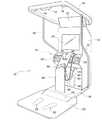
図1は、本発明の一実施形態に係るゲーム装置の外観を示す斜視図である。同図に示すゲーム装置10は各種遊技場に配置される業務用機であり、筐体12の下に該筐体12から前方に延びる基台18が取り付けられており、この基台18のさらに前方には基台18よりも薄いゲームステージ20が取り付けられている。ゲームステージ20の中央には足形52が描かれており、この足形52にプレイヤが足を合わせて立つと、筐体12に対して正対するようになっている。 FIG. 1 is a perspective view showing an appearance of a game device according to an embodiment of the present invention. The
基台18の最前方、すなわちゲームステージ20が取り付けられる箇所はスロープが形成されており、このスロープにフットコントローラ50が設けられている。フットコントローラ50の内部には感圧センサが内蔵されており、ゲームステージ20上に立ったプレイヤが左右どちらかの足を前に出し、フットコントローラ50上を踏むと、その旨が装置内部に通知されるようになっている。 A slope is formed in the forefront of the
筐体12は一般的な成人の身長よりも高く形成されており、その上部には略矩形の枠体14が取り付けられている。枠体14は、その前側が後ろ側よりも高い位置となるよう、やや斜めに配置されている。枠対14の奥側は筐体12の頂部に固定されており、さらに左右には一対の支持棒16の頂部に固定されている。これら一対の支持棒16は筐体12の左右側面に固定されている。そして、枠体14の前側には超音波発信器17及び超音波受信器13,15が設けられている。すなわち、筐体12に向かって左側上方に超音波受信器15が、右側上方に超音波受信器13が、中央上方に超音波発信器17が設けられている。超音波発信器17と超音波受信器13,15は同一直線上に配置されており、超音波発信器17は超音波受信器13,15のちょうど真ん中に取り付けられている。ゲーム装置10では、超音波発信器17から下方に超音波を発射し、その反射波を超音波受信器13,15で検知するまでの時間を計測するようにしている。これにより、超音波発信器17からプレイヤの頭までの距離とプレイヤの頭から超音波受信器13までの距離とを足し合わせた距離と、超音波発信器17からプレイヤの頭までの距離とプレイヤの頭から超音波受信器15までの距離とを足し合わせた距離と、の2つの距離を取得するようになっている。そして、これら2つの距離から、ゲームステージ20に立ったプレイヤの姿勢を検知するようになっている。 The
筐体12におけるプレイヤの眼前にはゲーム画面を表示するモニタ24が正対しており、その上部には広告板22が取り付けられている。モニタ24の下方は前方に迫り出し、迫り出し部26が形成されている。迫り出し部26の最前面にはゲーム効果音やゲーム音楽を出力するスピーカ28が取り付けられている。また、モニタ24の下方には、筐体幅よりも狭い幅の屈曲した縦長の板部材であるフロントプレート38の上端が取り付けられている。このフロントプレート38の下端は、基台18の上面に取り付けられ、基台18上に立設されている。フロントプレート38は基台18から略垂直に立ち上がった後、筐体12側に折れ曲がり、上述のように上端がモニタ24の下方に取り付けられている。 A
フロントプレート38の前面には選択ボタン34,36及び決定ボタン32が取り付けられており、プレイヤはこれらのボタンを押下することで各種の選択操作を行うことができるようになっている。また、選択ボタン34,36及び決定ボタン32の下方にはガンホルダも形成されており、非使用時にガンコントローラ30を掛けておくことができるようになっている。
ガンコントローラ30のグリップ部には信号ケーブル48及び保持ケーブル42の各一端が取り付けられている。信号ケーブル48の他端は筐体12内部に導入されており、ガンコントローラ30の銃身内部に設けられた光センサの検知結果(銃身方向の検知に用いられる)、及びトリガ信号が信号ケーブル48により筐体12内部に通知されている。また、保持ケーブル42の他端は筐体12の下部に強固に取り付けられており、ガンコントローラ30が容易に持ち去られないようにしている。 Each end of the
筐体12の下部にはコイン投入部40及びコイン返却部44が設けられており、またその下方にはコイン投入部40から投入され、内部の図示しないコイン箱に溜まったコインを回収するコイン回収扉46が設けられている。 A coin insertion unit 40 and a
以上の構成を有するゲーム装置10では、プレイヤは足形52に自分の足を合わせてゲームステージ20上に立ち、ガンコントローラ30を手にしてモニタ24に表示される敵に銃身を向け、トリガを引く。すると、仮想3次元空間において弾丸オブジェクトが射出され、敵に向かって飛んでいく。また、同様に敵からも弾丸オブジェクトが自身に向かって射出される。このとき、プレイヤが頭を左右にずらしたり、或いは体を屈めて頭を下げたりすると、弾丸オブジェクトを避けることができるようになっている。 In the
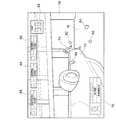
また、図2に示すように、このゲーム装置10は通信ネットワークに接続されており、他のゲーム装置10と共にネットワークシューティングゲームシステムを構成している。すなわち、同図に示すように、このネットワークシューティングゲームシステム60では、インターネット等の通信ネットワーク62に複数のゲーム装置10(ここではゲーム装置10−1〜10−nのn台)が接続されており、さらにロビーサーバ64も接続されている。各ゲーム装置10にはクライアント機能10aに加えて、サーバ機能10bも備えられており、ロビーサーバ64は、現在アクセスしてきているゲーム装置10の中からネットワークシューティングゲームに参加させる複数のゲーム装置10を決定する。例えばロビーサーバ64は、各ゲーム装置10のプレイヤのゲーム習熟度を取得して、それにより同程度のゲーム習熟度のプレイヤによりプレイされている複数のゲーム装置10を選択し、それらを同じネットワークシューティングゲームに参加させる。また、ロビーサーバ64は、こうして決定されるゲーム装置10の中から一台をゲームサーバとして選出する。そして、当該ゲーム装置10のサーバ機能10bを介して、当該ゲーム装置10のクライアント機能10a及び他のゲーム装置10のクライアント機能10aは仮想3次元空間の現在の状況を示すデータ等を授受し、それによりシューティングゲームの舞台となる仮想3次元空間を共有するようになっている。 As shown in FIG. 2, the
図3は、各ゲーム装置10のモニタ24に表示されるゲーム画面の一例を示している。このネットワークシューティングゲームシステム60では、各ゲーム装置10にプレイヤキャラクタオブジェクトが関連づけられており、ゲームに参加しているゲーム装置10に関連づけられたプレイヤキャラクタオブジェクトの全てが仮想3次元空間に配置されている。そして、ゲーム装置10では、該ゲーム装置10に関連づけられたプレイヤキャラクタオブジェクトの眼の位置に設けられた視点から仮想3次元空間を見た様子が、モニタ24にゲーム画面として表示されるようになっている。また、ゲーム画面には、自分の状況を示す自ステータス画像70及び他の参加者の状況を示す他ステータス画像66が表示されている。また、ゲーム開始からの経過時間を示す経過時間画像68も表示されている。 FIG. 3 shows an example of a game screen displayed on the
仮想3次元空間には、同図に示すように自動車オブジェクト72や建造物オブジェクト78や地面オブジェクト76のような静的オブジェクト(時間が経過すると位置や姿勢を変えないオブジェクト)の他に、プレイヤキャラクタオブジェクト(視点設定オブジェクト)74や弾丸オブジェクト(移動オブジェクト)80,82のような動的オブジェクト(時間が経過するとプログラムやゲーム操作に従って位置や姿勢を変えるオブジェクト)が配置されている。同図に示すゲーム画面は、あるプレイヤキャラクタオブジェクトの眼の位置に配置された視点から仮想3次元空間を見た様子を示しており、略中央にプレイヤキャラクタオブジェクト74が表示されている。また、その手前にプレイヤキャラクタオブジェクト74が手にしている玩具銃から発射されたペイントボール(樹脂製の小球であり、内部にペンキが封入されたもの)を示す弾丸オブジェクト80が表示されている。また、プレイヤキャラクタオブジェクト74の周囲には、当該ゲーム画面を表示するゲーム装置10に関連づけられたプレイヤキャラクタオブジェクト(不図示)により発射された弾丸オブジェクト82も表示されている。 In the virtual three-dimensional space, as shown in the figure, in addition to static objects such as a
また、本実施形態においては、弾丸オブジェクト80,82はペイントボールをシミュレートしたものであり、弾丸オブジェクト80,82が他のオブジェクト、例えば自動車オブジェクト72、建造物オブジェクト78、地面オブジェクト76、プレイヤキャラクタオブジェクト74等に当たると、破裂して内部のペンキが同オブジェクトに付着する様子が表現されるようになっている。ここでは、地面オブジェクト76及び自動車オブジェクト72上にペンキ跡オブジェクト84が配置されており、それらオブジェクトに弾丸オブジェクトが当たったことが示されている。特に、本実施形態では、弾丸オブジェクトがそれらオブジェクトに当たる際の方向(接触方向)を演算しており、この方向と接触面の方向(水平方向又は法線方向)とのなす角に応じたテクスチャ画像をペンキ跡オブジェクト84の表示に用いている。具体的には、接触方向と接触面の水平方向とのなす角が90度に近づくほど、円形に近いペンキ跡を示すテクスチャ画像を用いてペンキ跡オブジェクト84を表示している。また、接触方向と接触面の水平方向とのなす角が零度に近づくほど、横に延びたペンキ跡を示すテクスチャ画像を用いてペンキ跡オブジェクト84を表示している。このとき、ペンキ跡の延びる方向、すなわちペンキ跡オブジェクト84の配置方向は弾丸オブジェクトの接触方向に合致するようになっている。これにより、プレイヤはゲーム画面に表されたペンキ跡オブジェクト84を見て、仮想3次元空間のどこから発射された弾丸オブジェクトにより付着したものかを直ちに把握することができる。 In this embodiment, the bullet objects 80 and 82 simulate a paintball, and the bullet objects 80 and 82 are other objects such as a
以下、各ゲーム装置10の内部処理について詳細に説明する。 Hereinafter, the internal processing of each
図4は、ゲーム装置10のハードウェア構成図である。同図に示すように、このゲーム装置10はコンピュータゲームシステムであり、CPUやメモリ等により構成された制御部98を中心に構成されている。制御部98には、ガンコントローラ30、超音波発信器17、超音波受信器13,15、フットコントローラ50、記憶部90、ディスク読み取り装置94、通信部92、音声処理部102及び表示制御部100が接続されている。 FIG. 4 is a hardware configuration diagram of the
ガンコントローラ30は、ガン型のゲームコントローラであり、プレイヤがトリガを引いたタイミング、及びそのタイミングでのガンコントローラ30の指向方向(具体的にはモニタ24のどの位置をガンコントローラ30の銃身が向いているか)が制御部98に入力されるようになっている。超音波発信器17は、制御部98からの指示に従って超音波を発する。また、制御部98では超音波発信器17に超音波の発信を指示したタイミングから計時を開始する。さらに、超音波受信器13,15は、超音波発信器17から発せられた超音波を受信して、その受信波形を制御部98に渡す。そして、制御部98では、超音波受信器13,15から渡される受信波形に基づいて、プレイヤの頭での反射波が超音波受信器13,15に入射するタイミングを判断している。フットコントローラ50からは、プレイヤがフットコントローラ50を踏んだ旨が制御部98に通知されている。 The
記憶部90は、ハードディスク記憶装置やRAM等の各種データ記憶手段により構成されており、クライアント機能10a及びサーバ機能10bを実現するためのプログラムが格納されている。 The
ディスク読み取り装置94は、CD−ROMやDVD−ROM等のコンピュータ読み取り可能な情報記憶媒体であるディスク96からデータを読み取り、制御部98に供給する。ここでは、ゲーム装置10で実行される各種プログラムがディスク96からゲーム装置10に供給され、記憶部90にインストールされるものとする。 The
通信部92は、通信ネットワーク62に接続されており、ゲームサーバとして動作するゲーム装置10から、ネットワークシューティングゲームに参加している他のゲーム装置10の状況を示すデータ(後述する位置データ及び弾道データ)を受信する。また、自機(当該ゲーム装置10)の状況を示すデータ(後述する位置データ及び弾道データ)をゲームサーバとして動作するゲーム装置10に送信する。さらに、当該ゲーム装置10がサーバとして動作する場合には、他のゲーム装置10のクライアント機能10aからデータを受信すると、それをさらに他のゲーム装置10のクライアント機能10aに配信する。 The
音声処理部102にはスピーカ28,28が接続されており、制御部98からの制御に従ってゲーム効果音、ゲーム音楽その他の音声を出力する。例えば、弾丸オブジェクトの射出時には弾丸射出音を出力する。表示制御部100にはモニタ24が接続されており、制御部98からの制御に従って、例えば図3に示されるようなゲーム画面を表示出力する。
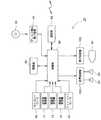
図5は、本ゲーム装置10の機能ブロック図である。ゲーム装置10は上記のように公知の構成を有するコンピュータゲームシステムであり、所定のプログラムを実行することにより種々の機能を実現している。同図に示すように、このゲーム装置10は、機能的には通信制御部200、他キャラクタ弾道データ記憶部202、他キャラクタ位置データ記憶部204、自キャラクタ弾道データ記憶部206、自キャラクタ位置データ記憶部208、左右シフト量更新部210、プレイヤ姿勢判定部212、基礎位置設定部216、自キャラクタ弾道データ生成部218、当たり予想部220、弾道データ補正部222、ゲーム画像生成部214を含んで構成されている。これらの機能は、ディスク96からゲーム装置10に供給されるプログラムを制御部98によって実行することにより実現されている。 FIG. 5 is a functional block diagram of the
まず、自キャラクタ弾道データ生成部218は、ガンコントローラ30からの入力に基づいて弾道データを生成する。すなわち、ガンコントローラ30から銃身方向を示すデータが入力されると、その時点の自キャラクタの位置座標(仮想3次元空間における絶対座標)を自キャラクタ位置データ記憶部208の記憶内容に基づいて生成する。この位置座標を弾丸オブジェクトの射出位置とし、それをガンコントローラ30から入力される銃身方向(射出方向)とともに弾道データとして自キャラクタ弾道データ記憶部206に格納する。図11(b)には、自キャラクタ弾道データ記憶部206に格納されるデータの構成が示されている。自キャラクタ弾道データ記憶部206に記憶された弾道データは通信制御部200により、サーバ機能10bを実行するゲーム装置10に送信される。サーバ機能10bを実行するゲーム装置10では、受信した弾道データをネットワークシューティングゲームに参加する他のゲーム装置10に配信する。そして、このデータは各ゲーム装置10の通信制御部200により受信され、他キャラクタ弾道データ記憶部202に格納される。図11(a)には、他キャラクタ弾道データ記憶部202に格納されるデータの構成が示されている。 First, the player character ballistic
他キャラクタ弾道データ記憶部202に新たに他のゲーム装置10で生成された弾道データが格納されると、当たり予想部220は、他キャラクタ弾道データ記憶部202に格納された弾道データと、自キャラクタ位置データ記憶部208の記憶内容に基づいて算出される、当該ゲーム装置10に関連づけられたプレイヤキャラクタオブジェクトの位置座標(絶対座標)と、に基づいて、弾丸オブジェクトが該プレイヤキャラクタオブジェクトに当たるか否かを予測する。すなわち、弾道データにより示される弾丸オブジェクトの予測軌道が、プレイヤキャラクタオブジェクトに設定されたヒットチェック(干渉判定)用の領域(不図示)に進入するか否かを判断する。弾丸オブジェクトの軌道は直線状であってもよいし、放物線状であってもよい。その他、種々の軌道を採用することができる。 When the ballistic data newly generated by the
弾道データ補正部222は、弾丸オブジェクトが前記ヒットチェック用の領域に進入する場合、すなわち弾丸オブジェクト306がプレイヤキャラクタPCの所定箇所に当たると評価される場合(図12(a)参照)に、他キャラクタ弾道データ記憶部202に格納された弾道データを、当該ゲーム装置10に関連づけられたプレイヤキャラクタオブジェクトPCの眼の位置に設定された視点VPの位置座標に基づいて補正する(図12(b)参照)。具体的には、軌道データ補正部222は、弾道データのうち射出方向304をプレイヤキャラクタPCの眼の位置に設定された視点VPの位置の側にずらして補正後の射出方向304aを得る。すなわち、弾丸オブジェクト306の射出位置と視点VPとを結ぶベクトルと、弾丸オブジェクト306の射出方向304のベクトルと、のなす角が小さくなるように、弾道データを構成する射出方向304(ベクトルデータ)を補正する。そして、補正後のデータを他キャラクタ弾道データ記憶部202に格納する。こうすれば、弾丸オブジェクト306はプレイヤキャラクタPCの視野範囲302内を移動することになり、仮想3次元空間の様子をスクリーン300に投影してゲーム画面を生成した場合に、弾丸オブジェクト306がそこに確実に表されることになる。 When the bullet object enters the hit check area, that is, when it is evaluated that the
また、ゲーム装置10では、図6に示すようにゲームの舞台となる仮想3次元空間に複数の基礎位置が設定されており、これらの位置座標及びIDが予め記憶されている。そして、各ゲームキャラクタオブジェクトは、いずれかの基礎位置を基準(配置基準位置)として、その実際の設置位置が決定されるようになっている。基礎位置設定部216は、当該ゲーム装置10に関連づけられたプレイヤキャラクタオブジェクトの基礎位置を配置基準位置として選択する。具体的には、ゲーム開始時には、予め定められた基礎位置を配置基準位置として選択する。そして、プレイヤ姿勢判定部212によりプレイヤがゲームステージ20上で左又は右に大きく体をずらしたまま所定時間以上経過したと判断すると、そのずらした向きに対応する仮想3次元空間の方向に設定されている基礎位置に配置基準位置を変更する。また、フットコントローラ50が踏まれると、プレイヤキャラクタの前方にある基礎位置に配置基準位置を変更する。 In the
さらに、基礎位置設定部216は、当該ゲーム装置10に関連づけられたプレイヤキャラクタオブジェクトが姿勢を向ける相手を、仮想3次元空間に配置された他のプレイヤキャラクタオブジェクトに中から選択し、そのプレイヤキャラクタに係る基礎位置を指向位置として管理している。具体的には、他キャラクタ位置データ記憶部204は、他のゲーム装置10において選択された基礎位置(配置基準位置)を格納しており、この中から1つを指向位置として選択している。基礎位置設定部216の選択結果(当該ゲーム装置10に関連づけられたプレイヤキャラクタオブジェクトの配置基準位置及び指向位置)は、いずれも自キャラクタ位置データ記憶部208に格納されている。 Further, the base
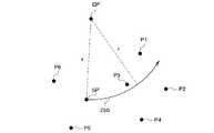
図10は、配置基準位置の再選択の方法を説明する図である。同図に示すように仮想3次元空間に基礎位置P1〜P6が配置されている場合、プレイヤキャラクタオブジェクトの現在位置SP’を通り、指向位置に配置された相手プレイヤキャラクタオブジェクト(相手オブジェクト)の位置を中心とする軌道250を算出する。この軌道250は、プレイヤの頭が筐体12に向かって左側にずれているとき平面視で反時計回りに延びる。また、右側にずれているとき平面視で時計回りに延びる。そして、軌道250に最も近い基礎位置(ここではP3)を新しい配置基準位置に選出する。 FIG. 10 is a diagram for explaining a method for reselecting the arrangement reference position. As shown in the figure, when the base positions P1 to P6 are arranged in the virtual three-dimensional space, the position of the opponent player character object (the opponent object) arranged at the pointing position through the current position SP ′ of the player character object. Is calculated. The
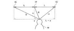
プレイヤ姿勢判定部212は、超音波発信器17、超音波受信器13,15を用いて、ゲームステージ20上に立つプレイヤの姿勢を判定する。すなわち、図8に示すように、超音波発信器17から超音波を発射し、プレイヤMの頭を反射して超音波受信器13,15に入射するまでの各時間を計測し、そこから超音波発信器17からプレイヤMの頭に至る距離l0とプレイヤMの頭から超音波受信器13に至る距離l1との和(l0+l1)、及び超音波発信器17からプレイヤMの頭に至る距離l0とプレイヤMの頭から超音波受信器15に至る距離l2との和(l0+l2)を取得する。さらに、図中Lの長さは既知であるから、これらの情報を元に、プレイヤMの頭の位置を特定するデータ(x及びy)を算出する。そして、yの値(プレイヤの頭の左右のシフト量)の絶対値が所定値以上の状態が所定時間以上継続する場合には、基礎位置設定部216にプレイヤの頭のずれ方向を通知する。これを受けて、基礎位置設定部216は配置基準位置の再選択を行う。 The player
一方、プレイヤ姿勢判定部212は、yの値の絶対値が所定値以上の状態が所定時間以上継続していない場合、当該yの値を左右シフト量更新部210に渡す。そして、左右シフト量更新部210は、このyの値に基づいてプレイヤキャラクタオブジェクトのシフト量を算出し、自キャラクタ位置データ記憶部208に記憶する。シフト量は、例えばプレイヤ姿勢判定部212から渡されるyの値そのものであってもよいし、順次生成されるyの値に平滑化等の各種処理を施してシフト量を算出してもよい。 On the other hand, if the state where the absolute value of the y value is greater than or equal to the predetermined value has not continued for a predetermined time or longer, the player
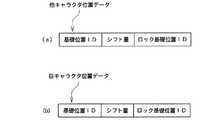
図9(b)には、自キャラクタ位置データ記憶部208に記憶されるデータの構成が示されている。同図に示すように、位置データは、配置基準位置として基礎位置設定部216により選択された基礎位置を識別する基礎位置ID、左右シフト量更新部210により設定されたシフト量、指向位置として基礎位置設定部216により選択された基礎位置を識別する基礎位置ID(ロック基礎位置ID)を含んで構成されている。 FIG. 9B shows the configuration of data stored in the own character position
図7は、シフト量、配置基準位置、プレイヤキャラクタの現在位置の関係を示している。同図において、太線の矢印はプレイヤキャラクタオブジェクトの姿勢を示している。同図においてSPは配置基準位置を示しており、SP’は最大距離のシフト後のプレイヤキャラクタオブジェクトの位置を示しており、EPは指向位置として選択された基礎位置を示している。プレイヤキャラクタオブジェクトは配置基準位置SPを中心として、左右シフト量更新部210により設定されるシフト量だけ、指向位置EPを指向した状態で左右に移動するようになっている。ここでは、プレイヤキャラクタのシフト方向を、配置基準位置SPから指向位置EPに向かう方向に対して垂直としたが、他の方向にシフトさせるようにしてもよい。また、シフト量は左右ともに一定距離(ここではともにL)に制限されている。 FIG. 7 shows the relationship between the shift amount, the arrangement reference position, and the current position of the player character. In the figure, a thick arrow indicates the posture of the player character object. In the drawing, SP indicates the arrangement reference position, SP ′ indicates the position of the player character object after the maximum distance shift, and EP indicates the base position selected as the directivity position. The player character object moves to the left and right in the state where the pointing position EP is directed by the shift amount set by the left and right shift
自キャラクタ位置データ記憶部208に格納されたデータは、通信制御部200によりサーバ機能10bを実行するゲーム装置10に送信される。このゲーム装置10は受信したデータをネットワークゲームに参加する他のゲーム装置10に配信する。通信制御部200では、こうして配信される位置データを受信すると、他キャラクタ位置データ記憶部204に格納する。図9(a)には、他キャラクタ位置データ記憶部204に格納されるデータの構成が示されている。 The data stored in the player character position
ゲーム画像生成部214は、他キャラクタ弾道データ記憶部202、他キャラクタ位置データ記憶部204、自キャラクタ弾道データ記憶部206、自キャラクタ位置データ記憶部208の各記憶内容に基づき、モニタ24に表示するゲーム画面を描画する。具体的には、他キャラクタ弾道データ記憶部202から弾道データを読み出し、該弾道データが示す仮想3次元空間内の軌道上に弾丸オブジェクを配置し、それを時間経過とともに移動させる。同様に、自キャラクタ弾道データ記憶部206から弾道データを読み出し、該弾道データが示す仮想3次元空間内の軌道上に弾丸オブジェクトを配置し、それを時間経過とともに移動させる。 The game
さらに、他キャラクタ位置データ記憶部204から位置データを読み出し、この位置データにより示される仮想3次元空間内の位置に他のゲーム装置10に関連づけられたプレイヤキャラクタオブジェクトを配置する。このとき、プレイヤキャラクタオブジェクトの姿勢は、指向位置(ロック基礎位置ID)に基づいて、現在位置から該指向位置を向くように決定する。また、シフト量だけ配置基準位置からシフトした位置にプレイヤキャラクタオブジェクトを配置する。同様に、自キャラクタ位置データ記憶部208から位置データを読み出し、この位置データにより示される仮想3次元空間内の位置に当該ゲーム装置10に関連づけられたプレイヤキャラクタオブジェクトを配置する。このときも、プレイヤキャラクタオブジェクトの姿勢は、指向位置(ロック基礎位置ID)に基づいて、現在位置から該指向位置を向くように決定する。また、シフト量だけ配置基準位置からシフトした位置にプレイヤキャラクタオブジェクトを配置する。 Further, the position data is read from the other character position
さらに、このゲーム装置10では、弾丸オブジェクトが他のオブジェクトに接触したか否かを判断する。そして、他のオブジェクトに接触していればその弾丸オブジェクトに係る弾道データを他キャラクタ弾道データ記憶部202又は自キャラクタ弾道データ206から削除する。そして、接触位置にペンキ跡を示す画像を表示する。このため、仮想3次元空間における弾丸オブジェクトが他のオブジェクトに接触した(当たった)位置にペンキ跡オブジェクトを配置している。 Furthermore, in this
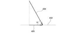
ペンキ跡オブジェクトの表示方法としては、以下に示す2通りが採用されている。すなわち、建造物オブジェクト78等の静的オブジェクトについては、図13に示すように、弾丸オブジェクト400が静的オブジェクト402に接触する場合に、図15に示すように、その接触位置404を中心とした箇所を静的オブジェクト402から切り取る。この際、図16に示すように、弾丸オブジェクト400の軌道から接触方向408を算出し、それを静的オブジェクト402に射影してベクトル409を得るとともに、ベクトル409と接触方向408とのなす角θを算出しておく。 The following two methods are employed for displaying the paint mark object. That is, for a static object such as a
そして、接触位置404を中心とした箇所を静的オブジェクト402から切り取る際、その切り取り箇所の向きを当該ベクトル409に従って決定する。その後、切り取ったペンキ跡オブジェクト406を構成するポリゴンを細分割し(図17参照)、そこにペンキ跡を示すテクスチャ画像をマッピングする。このとき、ペンキ跡を示すテクスチャ画像を予め複数用意しておき、それぞれを上記なす角θの範囲と関連づけて記憶しておく(図18参照)。そして、ペンキ跡オブジェクト406には、上記のようにして算出したなす角θに応じたテクスチャ画像を選択的に読み出し、マッピングする(図19参照)。その後、ペンキ跡オブジェクト406を元の静的オブジェクト402における弾丸オブジェクト400の接触位置に配置する。 Then, when a portion centered on the
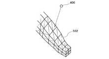
一方、プレイヤキャラクタオブジェクト等の動的オブジェクトについては、図20に示すように、動的オブジェクト500の周囲に該動的オブジェクトをすっぽりと包含する不可視のポリゴンモデル(ペンキ跡オブジェクト)502を配置しておく。このポリゴンモデル502は図21に示すように、動的オブジェクト500そのものよりも細かいポリゴンの組合せにより構成されており、任意の箇所に任意のテクスチャをマッピングできるようになっている。そして、弾丸オブジェクト400が動的オブジェクト500に接触する場合に、その接触位置に応じたポリゴンモデル502の位置を特定し(図22参照)、そこに図18のようにして予め準備されたペンキ跡テクスチャ画像をマッピングする(図23参照)。このときも、弾丸オブジェクト400の動的オブジェクト500に対する接触方向と、その接触面の方向と、のなす角に応じたテクスチャ画像を選択的に読み出し、接触箇所にマッピングする。 On the other hand, for a dynamic object such as a player character object, as shown in FIG. 20, an invisible polygon model (paint mark object) 502 that completely surrounds the
その後、ゲーム画像生成部214では、当該ゲーム装置10に関連づけられたプレイヤキャラクタオブジェクトの眼の位置に配置された視点から、仮想3次元空間を見た様子を画像化し、それをモニタ24により表示する。 Thereafter, in the game
以上説明したネットワークゲームシステムによれば、弾丸オブジェクトがプレイヤキャラクタオブジェクトに接触することが予測される場合に、弾丸オブジェクトの軌道を補正して、弾丸オブジェクトがプレイヤキャラクタ上に設定された視点に向かって移動するようにしたので、該視点から仮想3次元空間を見た様子をモニタ24に表示することで、弾丸オブジェクトが迫りくる様子を示すことができる。 According to the network game system described above, when a bullet object is predicted to come into contact with the player character object, the trajectory of the bullet object is corrected so that the bullet object moves toward the viewpoint set on the player character. Since the movement is made, the state in which the bullet object is approaching can be shown by displaying on the
また、各プレイヤキャラクタオブジェクトの位置を、予め定めた複数の基礎位置のいずれかに拘束しておき、それらの姿勢を、他のプレイヤキャラクタオブジェクトが拘束された基礎位置に基づいて算出するので、通信ネットワーク62のトラフィックの増大を抑えつつ、複数のゲーム装置10の間でそれらゲーム装置10に関連づけられたオブジェクトの位置及び姿勢を共有することができる。 In addition, since the position of each player character object is constrained to any of a plurality of predetermined base positions, and their postures are calculated based on the base positions where other player character objects are constrained, communication While suppressing an increase in traffic on the
さらに、弾丸オブジェクトが他のオブジェクトに接触した場合に、接触方向と接触面の方向とに応じた内容のテクスチャ画像がマッピングされたペンキ跡オブジェクトを表示するようにしたので、弾丸オブジェクトがどこから発射されたものであるかを、プレイヤはゲーム画面から直ちに理解することができるようになる。 Furthermore, when a bullet object touches another object, a paint mark object with a texture image mapped according to the contact direction and the direction of the contact surface is displayed, so where the bullet object is fired from. It is possible for the player to immediately understand whether or not the game is on the game screen.
10 ゲーム装置、10a クライアント機能、10b サーバ機能、12 筐体、13,15 超音波受信器、14 枠体、16 支持棒、17 超音波発信器、18 基台、20 ゲームステージ、22 広告板、24 モニタ、26 迫り出し部、28 スピーカ、30 ガンコントローラ、32 決定ボタン、34,36 選択ボタン、38 フロントプレート、40 コイン投入部、42 保持ケーブル、44 コイン返却部、46 コイン回収扉、48 信号ケーブル、50 フットコントローラ、52 足形、60 ネットワークシューティングゲームシステム、62 通信ネットワーク、64 ロビーサーバ、66 他ステータス画像、68 経過時間画像、70 自ステータス画像、72 自動車オブジェクト、74 プレイヤキャラクタオブジェクト、76 地面オブジェクト、78 建造物オブジェクト、80,82,306,400 弾丸オブジェクト、84,406 ペンキ跡オブジェクト、90 記憶部、92 通信部、94 ディスク読み取り装置、96 ディスク、98 制御部、100 表示制御部、102 音声処理部、200 通信制御部、202 他キャラクタ弾道データ記憶部、204 他キャラクタ位置データ記憶部、206 自キャラクタ弾道データ記憶部、208 自キャラクタ位置データ記憶部、210 左右シフト量更新部、212 プレイヤ姿勢判定部、214 ゲーム画像生成部、216 基礎位置設定部、218 自キャラクタ弾道データ生成部、220 当たり予想部、222 弾道データ補正部、250 軌道、300 スクリーン、302 視野範囲、304,304a 射出方向、402 静的オブジェクト、404 接触位置、408 接触方向、409 ベクトル、500 動的オブジェクト、502 ポリゴンモデル。 10 game devices, 10a client function, 10b server function, 12 housing, 13, 15 ultrasonic receiver, 14 frame, 16 support rod, 17 ultrasonic transmitter, 18 base, 20 game stage, 22 billboard, 24 monitor, 26 projection part, 28 speaker, 30 gun controller, 32 determination button, 34, 36 selection button, 38 front plate, 40 coin insertion part, 42 holding cable, 44 coin return part, 46 coin recovery door, 48 signal Cable, 50 Foot Controller, 52 Foot, 60 Network Shooting Game System, 62 Communication Network, 64 Lobby Server, 66 Other Status Image, 68 Elapsed Time Image, 70 Own Status Image, 72 Car Object, 74 Player Character Object , 76 Ground object, 78 Building object, 80, 82, 306, 400 Bullet object, 84, 406 Paint mark object, 90 Storage unit, 92 Communication unit, 94 Disc reader, 96 disc, 98 Control unit, 100 Display Control unit, 102 voice processing unit, 200 communication control unit, 202 other character ballistic data storage unit, 204 other character position data storage unit, 206 own character ballistic data storage unit, 208 own character position data storage unit, 210 update left / right shift amount , 212 player posture determination unit, 214 game image generation unit, 216 base position setting unit, 218 own character ballistic data generation unit, 220 hit prediction unit, 222 ballistic data correction unit, 250 trajectory, 300 screen, 302 field of view range, 3 4,304a emission direction, 402 static objects, 404 contact position, 408 contact direction, 409 vectors, 500 dynamic objects, 502 polygon model.
Claims (5)
Translated fromJapanese前記各ゲーム装置は、
前記各プレイヤオブジェクトの位置を示すデータと、複数の画像と、前記各画像に関連付けられた角の範囲を示すデータと、を記憶する記憶手段と、
前記ネットワークゲームシステムに含まれる通信ネットワークを介して接続された他のゲーム装置から送信される前記移動オブジェクトの軌道を示すデータを取得する軌道取得手段と、
前記移動オブジェクトが前記仮想空間に配置されたプレイヤオブジェクトと接触するか否かを、前記移動オブジェクトの軌道が前記プレイヤオブジェクトに設定された所定範囲に進入するか否かに基づいて判定する接触判定手段と、
前記接触判定手段により前記移動オブジェクトが前記プレイヤオブジェクトと接触すると判定される場合に、前記移動オブジェクトの軌道を示すデータに基づいて特定される、前記移動オブジェクトの前記プレイヤオブジェクトに対する接触方向を取得する接触方向取得手段と、
前記プレイヤオブジェクトの接触面の方向と前記接触方向とのなす角に基づいて特定される前記記憶手段に記憶されている画像を、前記プレイヤオブジェクトにおける前記移動オブジェクトの接触位置に応じた位置に表示するよう表示部を表示制御する接触画像表示手段と、を含み、
前記各プレイヤオブジェクトは、該プレイヤオブジェクトを覆う、前記プレイヤオブジェクトそのものよりも細かいポリゴンの組合せにより構成される不可視の被覆ポリゴンモデルを備えており、
前記接触画像表示手段は、前記接触位置に応じた前記被覆ポリゴンモデルの位置を特定して、特定された前記被覆ポリゴンモデルの位置に、前記プレイヤオブジェクトの接触面の方向と前記接触方向とのなす角に応じた画像をテクスチャ画像としてマッピングする、
ことを特徴とするネットワークゲームシステム。A network including a plurality of game devices connected to a communication network, sharing a virtual space where a plurality of player objects are arranged, and competing to hit a moving object launched from the position of each player object against another player object A game system,
Each of the game devices is
Storage means for storing data indicating the position of each player object, a plurality of images, and data indicating a range of corners associated with each image;
Trajectory acquisition means for acquiring data indicating the trajectory of the moving object transmitted from another game device connected via a communication network included in the network game system;
Contact determination meansfor determiningwhether or not the moving object comes into contact with theplayer object arranged in the virtual space based on whether or notthe trajectory of the moving object enters a predetermined range set for the player object When,
Contact the moving object by the contact determination means when it is determined that the contact with theplayer objectis identified based on data indicating a trajectory of the moving object, and acquires the contact direction with respect to theplayer object in the moving object Direction acquisition means;
An image stored in the storage means specified based on an angle formed by the direction of the contact surface of theplayer object and the contact direction is displayed at a position corresponding to the contact position of the moving object in theplayer object. Contact image display means forcontrolling display of the display unit,
Each player object includes an invisible covering polygon model that covers the player object and is configured by a combination of polygons finer than the player object itself,
The contact image display means specifies the position of the covering polygon model according to the contact position, and forms the position of the specified covering polygon model between the direction of the contact surface of the player object and the contact direction. Map the image according to the corner as a texture image,
A network game system characterized by that.
前記各ゲーム装置は、
複数の画像を記憶する画像記憶手段をさらに含み、
前記接触画像表示手段は、前記画像記憶手段に記憶される前記複数の画像の中から、前記他のオブジェクトの接触面の方向と前記接触方向とのなす角に応じた画像を選択的に読み出して表示部を表示制御する、
ことを特徴とするネットワークゲームシステム。The network game system accordingto claim1 ,
Each of the game devices is
Further comprising image storage means for storing a plurality of images,
Thecontact image display means selectively reads out an image corresponding to an angle formed by the direction of the contact surface of the other object and the contact direction from the plurality of images stored in the image storage means.Display control of the display unit ,
A network game system characterized by that.
前記各プレイヤオブジェクトの位置を示すデータと、複数の画像と、前記各画像に関連付けられた角の範囲を示すデータと、を記憶する記憶手段と、
前記他のゲーム装置から送信される前記移動オブジェクトの軌道を示すデータを取得する軌道取得手段と、
前記移動オブジェクトが前記仮想空間に配置されたプレイヤオブジェクトと接触するか否かを、前記移動オブジェクトの軌道が前記プレイヤオブジェクトに設定された所定範囲に進入するか否かに基づいて判定する接触判定手段と、
前記接触判定手段により前記移動オブジェクトが前記プレイヤオブジェクトと接触すると判定される場合に、前記移動オブジェクトの軌道を示すデータに基づいて特定される、前記移動オブジェクトの前記プレイヤオブジェクトに対する接触方向を取得する接触方向取得手段と、
前記プレイヤオブジェクトの接触面の方向と前記接触方向とのなす角に基づいて特定される前記記憶手段に記憶されている画像を、前記プレイヤオブジェクトにおける前記移動オブジェクトの接触位置に応じた位置に表示するよう表示部を表示制御する接触画像表示手段と、を含み、
前記各プレイヤオブジェクトは、該プレイヤオブジェクトを覆う、前記プレイヤオブジェクトそのものよりも細かいポリゴンの組合せにより構成される不可視の被覆ポリゴンモデルを備えており、
前記接触画像表示手段は、前記接触位置に応じた前記被覆ポリゴンモデルの位置を特定して、特定された前記被覆ポリゴンモデルの位置に、前記プレイヤオブジェクトの接触面の方向と前記接触方向とのなす角に応じた画像をテクスチャ画像としてマッピングする、
ことを特徴とするゲーム装置。A virtual space connected to a communication network together with other game devices, sharing a virtual space in which a plurality of player objects are arranged, is shared with the other game devices, and a moving object launched from the position of each player object is applied to the other player objects A game device competing for
Storage means for storing data indicating the position of each player object, a plurality of images, and data indicating a range of corners associated with each image;
Trajectory acquisition means for acquiring data indicating the trajectory of the moving object transmitted from the other game device;
Contact determination meansfor determiningwhether or not the moving object comes into contact with theplayer object arranged in the virtual space based on whether or notthe trajectory of the moving object enters a predetermined range set for the player object When,
Contact the moving object by the contact determination means when it is determined that the contact with theplayer objectis identified based on data indicating a trajectory of the moving object, and acquires the contact direction with respect to theplayer object in the moving object Direction acquisition means;
An image stored in the storage means specified based on an angle formed by the direction of the contact surface of theplayer object and the contact direction is displayed at a position corresponding to the contact position of the moving object in theplayer object. Contact image display means forcontrolling display of the display unit,
Each player object includes an invisible covering polygon model that covers the player object and is configured by a combination of polygons finer than the player object itself,
The contact image display means specifies the position of the covering polygon model according to the contact position, and forms the position of the specified covering polygon model between the direction of the contact surface of the player object and the contact direction. Map the image according to the corner as a texture image,
A game device characterized by that.
前記ゲーム装置が、前記各プレイヤオブジェクトの位置を示すデータと、複数の画像と、前記各画像に関連付けられた角の範囲を示すデータと、を記憶する記憶手段と、軌道取得手段と、接触判定手段と、接触方向取得手段と、接触画像表示手段と、を含み、
前記軌道取得手段が、前記他のゲーム装置から送信される前記移動オブジェクトの軌道を示すデータを取得する軌道取得ステップと、
前記接触判定手段が、前記移動オブジェクトが前記仮想空間に配置されたプレイヤオブジェクトと接触するか否かを、前記移動オブジェクトの軌道が前記プレイヤオブジェクトに設定された所定範囲に進入するか否かに基づいて判定する接触判定ステップと、
前記接触方向取得手段が、前記接触判定手段により前記移動オブジェクトが前記プレイヤオブジェクトと接触すると判定される場合に、前記移動オブジェクトの軌道を示すデータに基づいて特定される、前記移動オブジェクトの前記プレイヤオブジェクトに対する接触方向を取得する接触方向取得ステップと、
前記接触画像表示手段が、前記プレイヤオブジェクトの接触面の方向と前記接触方向とのなす角に基づいて特定される前記記憶手段に記憶されている画像を、前記プレイヤオブジェクトにおける前記移動オブジェクトの接触位置に応じた位置に表示するよう表示部を表示制御する接触画像表示ステップと、を含み、
前記各プレイヤオブジェクトは、該プレイヤオブジェクトを覆う、前記プレイヤオブジェクトそのものよりも細かいポリゴンの組合せにより構成される不可視の被覆ポリゴンモデルを備えており、
前記接触画像表示手段は、前記接触位置に応じた前記被覆ポリゴンモデルの位置を特定して、特定された前記被覆ポリゴンモデルの位置に、前記プレイヤオブジェクトの接触面の方向と前記接触方向とのなす角に応じた画像をテクスチャ画像としてマッピングする、
を含むことを特徴とするゲーム制御方法。A virtual space connected to a communication network together with other game devices, sharing a virtual space in which a plurality of player objects are arranged, is shared with the other game devices, and a moving object launched from the position of each player object is applied to the other player objectsA game control methodexecuted by agame device competing for
The game device stores data indicating the position of each player object, a plurality of images, and data indicating a range of corners associated with each image, trajectory acquisition means, contact determination Means, contact direction acquisition means, and contact image display means,
A trajectory acquisition step in which the trajectory acquisition means acquires data indicating a trajectory of the moving object transmitted from the other game device;
The contact determination means determines whether or not themoving object contacts aplayer object placed in the virtual space, and whether or notthe trajectory of the moving object enters a predetermined range set for the player object. A contact determination stepfor determining
Thecontact direction acquiring means, wherein when the moving objectby the contact determination means determines that the contact with theplayer objectis identified based on data indicating a trajectory of the moving object, theplayer object of the moving object A contact direction acquisition step of acquiring a contact direction with respect to
The contact image display means displaysan image stored in the storage means specified based on an angle formed by the direction of the contact surface of theplayer object and the contact direction, and the contact position of the moving object in theplayer objectanda contact image displaying stepof displaying controls the display unit to display at a position correspondingto,
Each player object includes an invisible covering polygon model that covers the player object and is configured by a combination of polygons finer than the player object itself,
The contact image display means specifies the position of the covering polygon model according to the contact position, and forms the position of the specified covering polygon model between the direction of the contact surface of the player object and the contact direction. Map the image according to the corner as a texture image,
A game control method comprising:
前記コンピュータは、制御手段と、前記プレイヤオブジェクトの位置を示すデータと、複数の画像と、前記各画像に関連付けられた角の範囲を示すデータと、を記憶する記憶手段と、を含み、
前記他のゲーム装置から送信される前記移動オブジェクトの軌道を示すデータを取得する軌道取得手段、
前記移動オブジェクトが前記仮想空間に配置されたプレイヤオブジェクトと接触するか否かを、前記移動オブジェクトの軌道が前記プレイヤオブジェクトに設定された所定範囲に進入するか否かに基づいて判定する接触判定手段、
前記接触判定手段により前記移動オブジェクトが前記プレイヤオブジェクトと接触すると判定される場合に、前記移動オブジェクトの軌道を示すデータに基づいて特定される、前記移動オブジェクトの前記プレイヤオブジェクトに対する接触方向を取得する接触方向取得手段、及び
前記プレイヤオブジェクトの接触面の方向と前記接触方向とのなす角に基づいて特定される前記記憶手段に記憶されている画像を、前記プレイヤオブジェクトにおける前記移動オブジェクトの接触位置に応じた位置に表示するよう表示部を表示制御する接触画像表示手段、として前記制御手段を機能させ、
前記各プレイヤオブジェクトは、該プレイヤオブジェクトを覆う、前記プレイヤオブジェクトそのものよりも細かいポリゴンの組合せにより構成される不可視の被覆ポリゴンモデルを備えており、
前記接触画像表示手段は、前記接触位置に応じた前記被覆ポリゴンモデルの位置を特定して、特定された前記被覆ポリゴンモデルの位置に、前記プレイヤオブジェクトの接触面の方向と前記接触方向とのなす角に応じた画像をテクスチャ画像としてマッピングする、
ことを特徴とするプログラム。
A virtual space connected to a communication network together with other game devices, sharing a virtual space in which a plurality of player objects are arranged, is shared with the other game devices, and a moving object launched from the position of each player object is applied to the other player objects A program for causing a computer to function as a game device that competes for
The computer includes storage means for storing control means, data indicating the position of the player object, a plurality of images, and data indicating a range of corners associated with each image,
Trajectory acquisition means for acquiring data indicating the trajectory of the moving object transmitted from the other game device;
Contact determination meansfor determiningwhether or not the moving object comes into contact with theplayer object arranged in the virtual space based on whether or notthe trajectory of the moving object enters a predetermined range set for the player object ,
Contact the moving object by the contact determination means when it is determined that the contact with theplayer objectis identified based on data indicating a trajectory of the moving object, and acquires the contact direction with respect to theplayer object in the moving objectAn image stored in the storage means that is specified based on an angle formed by a direction acquisition means and a direction of a contact surface of theplayer object and the contact direction, in accordance with a contact position of the moving object in theplayer object Thecontrol unit functions asa contact image display unit thatcontrols display of the display unit so as to display it at a selected position,
Each player object includes an invisible covering polygon model that covers the player object and is configured by a combination of polygons finer than the player object itself,
The contact image display means specifies the position of the covering polygon model according to the contact position, and forms the position of the specified covering polygon model between the direction of the contact surface of the player object and the contact direction. Map the image according to the corner as a texture image,
A programcharacterized by that .
Priority Applications (6)
| Application Number | Priority Date | Filing Date | Title |
|---|---|---|---|
| JP2005190329AJP4563266B2 (en) | 2005-06-29 | 2005-06-29 | NETWORK GAME SYSTEM, GAME DEVICE, GAME DEVICE CONTROL METHOD, AND PROGRAM |
| PCT/JP2006/312994WO2007001051A1 (en) | 2005-06-29 | 2006-06-29 | Network game system, game machine, game machine control method, and information storage medium |
| EP06767611AEP1900403A4 (en) | 2005-06-29 | 2006-06-29 | Network game system, game machine, game machine control method, and information storage medium |
| CA002613667ACA2613667A1 (en) | 2005-06-29 | 2006-06-29 | Network game system, game machine, game machine control method, and information storage medium |
| US11/994,401US20090104995A1 (en) | 2005-06-29 | 2006-06-29 | Network game system, game machine, game machine control method, and information storage medium |
| KR1020077029449AKR100929995B1 (en) | 2005-06-29 | 2006-06-29 | Network game system, game device, control method and information storage medium of game device |
Applications Claiming Priority (1)
| Application Number | Priority Date | Filing Date | Title |
|---|---|---|---|
| JP2005190329AJP4563266B2 (en) | 2005-06-29 | 2005-06-29 | NETWORK GAME SYSTEM, GAME DEVICE, GAME DEVICE CONTROL METHOD, AND PROGRAM |
Publications (2)
| Publication Number | Publication Date |
|---|---|
| JP2007007064A JP2007007064A (en) | 2007-01-18 |
| JP4563266B2true JP4563266B2 (en) | 2010-10-13 |
Family
ID=37595296
Family Applications (1)
| Application Number | Title | Priority Date | Filing Date |
|---|---|---|---|
| JP2005190329AExpired - LifetimeJP4563266B2 (en) | 2005-06-29 | 2005-06-29 | NETWORK GAME SYSTEM, GAME DEVICE, GAME DEVICE CONTROL METHOD, AND PROGRAM |
Country Status (6)
| Country | Link |
|---|---|
| US (1) | US20090104995A1 (en) |
| EP (1) | EP1900403A4 (en) |
| JP (1) | JP4563266B2 (en) |
| KR (1) | KR100929995B1 (en) |
| CA (1) | CA2613667A1 (en) |
| WO (1) | WO2007001051A1 (en) |
Families Citing this family (8)
| Publication number | Priority date | Publication date | Assignee | Title |
|---|---|---|---|---|
| JP4852555B2 (en)* | 2008-01-11 | 2012-01-11 | 株式会社コナミデジタルエンタテインメント | Image processing apparatus, image processing method, and program |
| US8393968B2 (en)* | 2008-09-03 | 2013-03-12 | Igt | Gaming system, gaming device and method for providing a strategy game having a plurality of awards |
| JP5443832B2 (en)* | 2009-05-29 | 2014-03-19 | 任天堂株式会社 | GAME PROGRAM AND GAME DEVICE |
| US20110099476A1 (en)* | 2009-10-23 | 2011-04-28 | Microsoft Corporation | Decorating a display environment |
| JP2013085345A (en)* | 2011-10-07 | 2013-05-09 | Nissan Motor Co Ltd | Connector holder and charging stand |
| JP2015166890A (en)* | 2014-03-03 | 2015-09-24 | ソニー株式会社 | Information processing apparatus, information processing system, information processing method, and program |
| JP2015192753A (en)* | 2014-03-31 | 2015-11-05 | 株式会社バンダイナムコエンターテインメント | game apparatus and program |
| JP6572137B2 (en)* | 2016-01-20 | 2019-09-04 | 株式会社東芝 | Three-dimensional data processing apparatus and method |
Family Cites Families (27)
| Publication number | Priority date | Publication date | Assignee | Title |
|---|---|---|---|---|
| TW284870B (en)* | 1994-01-26 | 1996-09-01 | Hitachi Ltd | |
| WO1995035555A1 (en)* | 1994-06-20 | 1995-12-28 | Sega Enterprises Ltd. | Method and apparatus for processing image |
| JPH08329276A (en)* | 1995-06-01 | 1996-12-13 | Ricoh Co Ltd | 3D graphics processor |
| JPH09161095A (en)* | 1995-12-07 | 1997-06-20 | Sega Enterp Ltd | Image processing device |
| TW346611B (en)* | 1996-03-28 | 1998-12-01 | Sega Enterprises Kk | An image processor, a game machine using the image processor, a method of image processing and a medium |
| JP4042188B2 (en)* | 1997-11-21 | 2008-02-06 | 株式会社セガ | Image processing device |
| JP3269797B2 (en)* | 1997-12-12 | 2002-04-02 | 株式会社ナムコ | Image generation device and information storage medium |
| JP2939223B2 (en)* | 1997-12-12 | 1999-08-25 | 株式会社ナムコ | Image generation device and information storage medium |
| JP4186136B2 (en)* | 1998-10-08 | 2008-11-26 | 株式会社セガ | Image processing apparatus and image processing method |
| JP3662435B2 (en)* | 1998-12-17 | 2005-06-22 | コナミ株式会社 | Shooting video game equipment |
| US20010003708A1 (en)* | 1999-12-10 | 2001-06-14 | Takuya Aizu | Entertainment system, entertainment apparatus, recording medium, and program |
| JP3753911B2 (en)* | 2000-02-08 | 2006-03-08 | 株式会社タイトー | Game device |
| JP3417917B2 (en)* | 2000-10-31 | 2003-06-16 | コナミ株式会社 | 3D image processing method, apparatus thereof, computer-readable recording medium recording 3D image processing program, and video game apparatus |
| JP3799553B2 (en)* | 2000-12-14 | 2006-07-19 | 株式会社セガ | GAME DEVICE, COMMUNICATION GAME SYSTEM, AND RECORDING MEDIUM |
| JP3442754B2 (en)* | 2001-08-10 | 2003-09-02 | 株式会社コナミコンピュータエンタテインメント東京 | Gun shooting game apparatus, computer control method and program |
| JP3843242B2 (en)* | 2002-02-28 | 2006-11-08 | 株式会社バンダイナムコゲームス | Program, information storage medium, and game device |
| JP3686920B2 (en)* | 2002-05-21 | 2005-08-24 | コナミ株式会社 | 3D image processing program, 3D image processing method, and video game apparatus |
| JP3901644B2 (en)* | 2003-01-30 | 2007-04-04 | 株式会社東芝 | Texture image compression apparatus and method, texture image extraction apparatus and method, data structure, and storage medium |
| JP3735358B2 (en)* | 2003-09-12 | 2006-01-18 | コナミ株式会社 | Video game program, video game apparatus, and video game method |
| JP2005122479A (en)* | 2003-10-16 | 2005-05-12 | Namco Ltd | Program, information storage medium, and image generation apparatus |
| JP4408681B2 (en)* | 2003-10-22 | 2010-02-03 | 株式会社バンダイナムコゲームス | Program, information storage medium, and image generation system |
| JP4179162B2 (en)* | 2003-12-26 | 2008-11-12 | 株式会社セガ | Information processing device, game device, image generation method, and game image generation method |
| JP3967720B2 (en)* | 2004-01-08 | 2007-08-29 | 株式会社コナミデジタルエンタテインメント | Image processing apparatus, program, and image processing method |
| JP4673570B2 (en)* | 2004-03-31 | 2011-04-20 | 株式会社セガ | Image generation apparatus, image display method, and program |
| JP3877077B2 (en)* | 2004-08-31 | 2007-02-07 | 任天堂株式会社 | Game device and image processing program |
| US7775882B2 (en)* | 2006-06-12 | 2010-08-17 | Kabushiki Kaisha Sega | Game apparatus for changing a visual point position of a virtual camera in conjunction with an attack by and enemy character |
| JP5101080B2 (en)* | 2006-10-19 | 2012-12-19 | 任天堂株式会社 | GAME PROGRAM, GAME DEVICE, GAME SYSTEM, AND GAME CONTROL METHOD |
- 2005
- 2005-06-29JPJP2005190329Apatent/JP4563266B2/ennot_activeExpired - Lifetime
- 2006
- 2006-06-29EPEP06767611Apatent/EP1900403A4/ennot_activeWithdrawn
- 2006-06-29KRKR1020077029449Apatent/KR100929995B1/ennot_activeExpired - Fee Related
- 2006-06-29CACA002613667Apatent/CA2613667A1/ennot_activeAbandoned
- 2006-06-29USUS11/994,401patent/US20090104995A1/ennot_activeAbandoned
- 2006-06-29WOPCT/JP2006/312994patent/WO2007001051A1/enactiveApplication Filing
Also Published As
| Publication number | Publication date |
|---|---|
| JP2007007064A (en) | 2007-01-18 |
| EP1900403A4 (en) | 2009-10-14 |
| KR100929995B1 (en) | 2009-12-07 |
| CA2613667A1 (en) | 2007-01-04 |
| KR20080016654A (en) | 2008-02-21 |
| WO2007001051A1 (en) | 2007-01-04 |
| EP1900403A1 (en) | 2008-03-19 |
| US20090104995A1 (en) | 2009-04-23 |
Similar Documents
| Publication | Publication Date | Title |
|---|---|---|
| KR100950880B1 (en) | Network game system, control method of network game system, game device, control method and information storage medium of game device | |
| JP3561463B2 (en) | Virtual camera viewpoint movement control method and 3D video game apparatus in 3D video game | |
| KR100509538B1 (en) | A 3-dimensional confronting video game device and a controllor thereof | |
| US6509896B1 (en) | Image processor, image processing method, medium and game machine | |
| US9289680B2 (en) | Game controller, storage medium storing game program, and game apparatus | |
| EP1287863A2 (en) | Gun shooting game device, method of controlling computer program | |
| EP2478944A2 (en) | Apparatus and method for displaying player character showing special movement state in network game | |
| JP5457071B2 (en) | GAME PROGRAM, GAME DEVICE, GAME SYSTEM, AND GAME CONTROL METHOD | |
| KR100929995B1 (en) | Network game system, game device, control method and information storage medium of game device | |
| US10653959B2 (en) | Image processing apparatus and image processing method for displaying video image capable of achieving improved operability and realism, and non-transitory storage medium encoded with computer readable program for controlling image processing apparatus | |
| US9526987B2 (en) | Storage medium, game apparatus, game system and game controlling method | |
| US20080076498A1 (en) | Storage medium storing a game program, game apparatus and game controlling method | |
| JP2002052243A (en) | Competition type video game | |
| US7119817B1 (en) | Image generating system and program | |
| US20120309521A1 (en) | Game device, game method, non-transitory storage medium encoded with computer readable program for controlling game device, and game system, allowing for fun in tactics and enhanced zest of game | |
| US20090093314A1 (en) | Game program and game apparatus | |
| JP4563267B2 (en) | Network game system, network game control method, game device, game control method, and program | |
| JP4861706B2 (en) | NETWORK GAME SYSTEM, NETWORK GAME SYSTEM CONTROL METHOD, GAME DEVICE, GAME DEVICE CONTROL METHOD, AND PROGRAM | |
| JP4445707B2 (en) | Virtual camera viewpoint movement control method and 3D video game apparatus in 3D video game | |
| HK1114042B (en) | Network game system, network game system control method, game machine and game machine control method | |
| HK1023201B (en) | Game machine and recording medium |
Legal Events
| Date | Code | Title | Description |
|---|---|---|---|
| A621 | Written request for application examination | Free format text:JAPANESE INTERMEDIATE CODE: A621 Effective date:20080423 | |
| A131 | Notification of reasons for refusal | Free format text:JAPANESE INTERMEDIATE CODE: A131 Effective date:20100316 | |
| A521 | Request for written amendment filed | Free format text:JAPANESE INTERMEDIATE CODE: A523 Effective date:20100512 | |
| TRDD | Decision of grant or rejection written | ||
| A01 | Written decision to grant a patent or to grant a registration (utility model) | Free format text:JAPANESE INTERMEDIATE CODE: A01 Effective date:20100720 | |
| A01 | Written decision to grant a patent or to grant a registration (utility model) | Free format text:JAPANESE INTERMEDIATE CODE: A01 | |
| A61 | First payment of annual fees (during grant procedure) | Free format text:JAPANESE INTERMEDIATE CODE: A61 Effective date:20100728 | |
| FPAY | Renewal fee payment (event date is renewal date of database) | Free format text:PAYMENT UNTIL: 20130806 Year of fee payment:3 | |
| R150 | Certificate of patent or registration of utility model | Ref document number:4563266 Country of ref document:JP Free format text:JAPANESE INTERMEDIATE CODE: R150 Free format text:JAPANESE INTERMEDIATE CODE: R150 | |
| FPAY | Renewal fee payment (event date is renewal date of database) | Free format text:PAYMENT UNTIL: 20130806 Year of fee payment:3 | |
| FPAY | Renewal fee payment (event date is renewal date of database) | Free format text:PAYMENT UNTIL: 20140806 Year of fee payment:4 | |
| R250 | Receipt of annual fees | Free format text:JAPANESE INTERMEDIATE CODE: R250 | |
| R250 | Receipt of annual fees | Free format text:JAPANESE INTERMEDIATE CODE: R250 | |
| R250 | Receipt of annual fees | Free format text:JAPANESE INTERMEDIATE CODE: R250 | |
| R250 | Receipt of annual fees | Free format text:JAPANESE INTERMEDIATE CODE: R250 | |
| R250 | Receipt of annual fees | Free format text:JAPANESE INTERMEDIATE CODE: R250 | |
| R250 | Receipt of annual fees | Free format text:JAPANESE INTERMEDIATE CODE: R250 | |
| R250 | Receipt of annual fees | Free format text:JAPANESE INTERMEDIATE CODE: R250 | |
| R250 | Receipt of annual fees | Free format text:JAPANESE INTERMEDIATE CODE: R250 | |
| R250 | Receipt of annual fees | Free format text:JAPANESE INTERMEDIATE CODE: R250 | |
| R250 | Receipt of annual fees | Free format text:JAPANESE INTERMEDIATE CODE: R250 | |
| R250 | Receipt of annual fees | Free format text:JAPANESE INTERMEDIATE CODE: R250 | |
| R250 | Receipt of annual fees | Free format text:JAPANESE INTERMEDIATE CODE: R250 | |
| EXPY | Cancellation because of completion of term |