JP4561035B2 - Fuel cell system - Google Patents
Fuel cell systemDownload PDFInfo
- Publication number
- JP4561035B2 JP4561035B2JP2003047707AJP2003047707AJP4561035B2JP 4561035 B2JP4561035 B2JP 4561035B2JP 2003047707 AJP2003047707 AJP 2003047707AJP 2003047707 AJP2003047707 AJP 2003047707AJP 4561035 B2JP4561035 B2JP 4561035B2
- Authority
- JP
- Japan
- Prior art keywords
- fuel
- gas
- hydrogen
- fuel gas
- fuel cell
- Prior art date
- Legal status (The legal status is an assumption and is not a legal conclusion. Google has not performed a legal analysis and makes no representation as to the accuracy of the status listed.)
- Expired - Fee Related
Links
Images


Classifications
- Y—GENERAL TAGGING OF NEW TECHNOLOGICAL DEVELOPMENTS; GENERAL TAGGING OF CROSS-SECTIONAL TECHNOLOGIES SPANNING OVER SEVERAL SECTIONS OF THE IPC; TECHNICAL SUBJECTS COVERED BY FORMER USPC CROSS-REFERENCE ART COLLECTIONS [XRACs] AND DIGESTS
- Y02—TECHNOLOGIES OR APPLICATIONS FOR MITIGATION OR ADAPTATION AGAINST CLIMATE CHANGE
- Y02E—REDUCTION OF GREENHOUSE GAS [GHG] EMISSIONS, RELATED TO ENERGY GENERATION, TRANSMISSION OR DISTRIBUTION
- Y02E60/00—Enabling technologies; Technologies with a potential or indirect contribution to GHG emissions mitigation
- Y02E60/30—Hydrogen technology
- Y02E60/50—Fuel cells
Landscapes
- Fuel Cell (AREA)
Description
Translated fromJapanese【0001】
【発明の属する技術分野】
この発明は、燃料電池システムに係り、詳しくは、起動時に燃料ガスを短時間で大量に供給し得る燃料電池システムに関するものである。
【0002】
【従来の技術】
従来、高分子電解質膜を使用した燃料電池では、電解質膜を挟んだ両側で燃料ガス或いは酸化ガスがイオン化し、そのイオンが電解質膜を透過して電気化学的な反応を生じるものであるから、電解質膜を挟んで燃料ガスと酸化ガスが存在していれば、両者の電気化学的な反応が継続する。このため、従来では、燃料電池の運転を停止するために、燃料電池への燃料ガスおよび酸化ガスの供給を停止し、かつ、燃料極側には、燃料ガスの変わりに空気や窒素等の置換ガスを送り込み、停止後に反応が起こらない構成を採用している。
そして、運転起動時には、燃料室に燃料ガスを送り込むことにより、置換ガスを外部に排出し反応を開始させる構成がとられている。
【0003】
一方、特開平11−26003号に記載されているように、燃料室内において、燃料ガスの濃度が他の領域より特に濃い領域と、酸化ガスの濃度が他の領域により特に濃い領域が併存する状態、即ち、同一の燃料室内で、燃料ガスと酸化ガスが偏在した状態が発生すると、燃料ガスが偏在した部分が局部電池を形成し、酸化ガスが偏在した部分に正常発電時と逆向きの電流を流すように働くため、特に酸素極を腐食させることなり、酸素極又は電解質膜の劣化が速くなるという問題がある。
燃料室の残留燃料ガスをパージする構成としては、例えば以下に示す文献が挙げられる。
【0004】
【特許文献1】
特開平02−33866号。
【0005】
【発明が解決しようとする課題】
上記特許文献1においては、燃料極に供給されている反応ガスに代わって、不活性ガスが供給される構成となっているが、配置スペースの少ない車両等に燃料電池を搭載する場合を想定すると、停止時の燃料電池のために不活性ガス容器を搭載することは、好ましくない。
【0006】
また、停止状態において燃料極のガスを空気に置換する構成とすると、起動時に燃料ガスを供給する際、燃料室内では瞬間的に燃料ガスと空気との偏在が発生する。この偏在によって、電気化学反応が生じ、これによって電極が劣化するという問題があった。
この発明は、電極の劣化を抑制できる燃料電池システムを提供することを目的とする。
【0007】
【課題を解決するための手段】
以上のような目的は、以下の本発明によって達成される。
(1)複数の単位セルと複数のセパレータとを交互に積層して構成され、各単位セルの燃料極とセパレータとの間に形成された燃料保持部と、各燃料保持部にそれぞれ連通する燃料流入通路と、各燃料保持部にそれぞれ連通する燃料流出通路とを備えた積層単位体を複数重ね合わせ、
各積層単位体は、燃料ガスの下流側に隣接する積層単位体の燃料流入通路に燃料流出通路が、燃料ガスの上流側に隣接する積層単位体の燃料流出通路に燃料流入通路がそれぞれ連通され、
燃料ガスの最も上流に位置している積層単位体の燃料流入通路には、燃料供給口が、最も下流に位置している積層単位体の燃料流出通路には、燃料排出口が設けられている燃料電池スタックと、
一端が前記燃料供給口に接続され、他端が前記燃料排出口に接続された燃料ガス循環路と、
前記燃料ガス循環路に設けられ、前記燃料排出口側から燃料ガスを吸引して循環させるポンプと、
前記燃料ガス循環路に接続され、前記燃料ガス循環路を介して前記燃料供給口へ燃料ガスを送る燃料ガス導通路と、
前記燃料ガス導通路に設けられ、開放時に通常運転時のガス圧に比べて高い圧力で燃料ガスを供給する起動用燃料ガス供給弁と、
一端がポンプと燃料排出口の間に接続され、他端が燃料ガス排出路に接続されている起動時排出回路と、
前記起動時排出回路に設けられた起動用燃料ガス排気弁と、
前記起動用燃料ガス排気弁と起動用燃料ガス供給弁とは、起動時から通常運転状態に移行するまでの間のみ開放されることを特徴とする燃料電池システム。
【0009】
(2) 単位セルとセパレータを交互に積層することによって構成される燃料電池スタックであって、
各単位セルの燃料極とセパレータとの間に形成された燃料保持部と、
前記単位セルと前記セパレータの積層方向に沿って設けられ、各燃料保持部にそれぞれ連通する2つの燃料流通路を有し、
一方の燃料流通路には燃料供給口が、他方の燃料流通路には燃料排出口が設けられており、
燃料流通路は、各単位セルとセパレータが積層された際に相互に重なり合う位置に形成された孔を積層することで形成され、
一方の燃料流通路に対応した位置に孔を有し、他方の燃料流通路に対応した位置に孔を有さない遮蔽板が、孔の位置を交互に変えて所定間隔で介挿されている燃料電池スタックと、
一端が前記燃料供給口に接続され、他端が前記燃料排出口に接続された燃料ガス循環路と、
前記燃料ガス循環路に設けられ、前記燃料排出口側から燃料ガスを吸引して循環させるポンプと、
前記燃料ガス循環路に接続され、前記燃料ガス循環路を介して前記燃料供給口へ燃料ガスを送る燃料ガス導通路と、
前記燃料ガス導通路に設けられ、開放時に通常運転時のガス圧に比べて高い圧力で燃料ガスを供給する起動用燃料ガス供給弁と、
一端がポンプと燃料排出口の間に接続され、他端が燃料ガス排出路に接続されている起動時排出回路と、
前記起動時排出回路に設けられた起動用燃料ガス排気弁と、
前記起動用燃料ガス排気弁と起動用燃料ガス供給弁とは、起動時から通常運転状態に移行するまでの間のみ開放されることを特徴とする燃料電池システム。
【0013】
【発明の実施の形態】
次にこの発明の好適実施形態について説明する。この実施形態は、電気自動車に搭載される燃料電池システムである。図1は、この発明の燃料電池システム1を示すブロック図である。図1に示されているように、この燃料電池システム1は燃料電池スタック100、空気供給系12、水素供給手段としての高圧水素タンク11を含む燃料供給系10、水供給系50から大略構成される。
【0014】
この燃料電池スタック100の構成について説明する。燃料電池スタック100は、燃料電池単位セル15と燃料電池セパレータ13とを交互に積層して構成されている。図2は、燃料電池用セパレータ13を示す全体正面図、図3は、燃料電池セパレータ13で構成された燃料電池スタック100の部分断面平面図(図2におけるA‐A断面図)、図4は、同じく部分断面側面図(図2及び図3におけるB−B断面図)、図5は、燃料電池セパレータ13の部分断面側面図(図2及び図3におけるC−C断面図)、図6は、燃料電池用セパレータ13の全体背面図である。
【0015】
セパレータ13は、単位セル15の電極に接触して電流を外部に取り出すための集電部材3、4と、各集電部材3、4の周端部に外装される枠体8、9とを備えている。
集電部材3、4は金属板で構成されている。構成金属は、導電性と耐食性を備えた金属で、例えば、ステンレス、ニッケル合金、チタン合金等に耐蝕導電処理を施したもの等が挙げられる。さらに、集電部材3、4は、カーボンで構成されたものを使用することもできる。
【0016】
集電部材3は、単位セル15の燃料極に接触し、集電部材4は酸素極に接触する。集電部材3は、矩形の板材から成り、その表面には、プレス加工によって、突出形成された複数の柱状凸部32が形成されている。柱状凸部32は、板材の短辺と長辺とに沿って縦横に等間隔で配列されている。柱状凸部32の間には、長辺に沿って(図2における横方向)配置された柱状凸部32の間に形成された溝によって、水素流路301が、短辺に沿って(図2における縦方向)配置された柱状凸部32の間に形成された溝によって、水素流路302が形成されている。この柱状凸部32の頂点部分の面は、燃料極が接触する当接部321となっている。また、柱状凸部32の裏側は、穴33となっている。集電部材3の両端部には、孔35が形成され、セパレータ13を積層した場合に、この孔35によって水素供給路が構成される。
【0017】
集電部材4は、矩形の板材から成り、プレス加工によって、複数の凸状部42が形成されている。凸状部42は、板材の短辺に平行に直線状に連続して形成されており、等間隔で配置されている。凸状部42の間には、溝が形成されて、空気が流通する空気流路40が形成されている。この凸状部42の頂点部分の面は、酸素極が接触する当接部421となっている。また、凸状部42の裏側は溝状の中空部となっており、この中空部によって冷却流路41が形成されている。空気流路40と、冷却流路41は、板材の端部まで達し、両端は、板材の端辺部で開口する開口部を備えている。集電部材4の両端部には、孔48が形成され、セパレータ13を積層した場合には、重ねられた孔48によって水素供給路が構成される。
【0018】
以上のような集電部材3、4は、各柱状凸部32と凸状部42が外側となるように重ね合わされて固定される。このとき、水素流路301、302の裏側面34と空気流路40の裏側面403が当接した状態となり、相互に通電可能な状態となる。また、集電部材3、4を重ね合わせることによって、図4に示されているように、冷却流路41が形成され、穴33は冷却流路41の一部を構成する。
また、空気流路40は、図3及び図5に示されているように、単位セル15に重ね合わされ、溝の開口部400を閉鎖することにより、管状の流路が構成され、空気流路40の内壁の一部が酸素極で構成される。この空気流路40から、単位セル15の酸素極に酸素と水が供給される。
【0019】
空気流路40の一端側開口部は、空気と水が流入する導入口43となり、他端の開口部は、空気と水が流出する導出口44となっている。また、冷却流路41の一端側開口部は、空気と水が流入する流入開放口45となり、他端の開口部は、空気と水が流出する流出開放口46となっている。以上のような構成において、空気流路40と冷却流路41は、交互に平行に配置され、相互に側壁47を挟んで隣接した構成となっている。このため、導入口43と流入開放口45も交互に配置され、導出口44と流出開放口46も交互に配置される。また、空気と水は、側壁47に沿って流れるため、側壁47は、冷却フィンとしての作用も発揮する。空気流路40と冷却流路41が交互に、かつ平行に配置されることで、燃料電池の冷却効率が向上し、均一な冷却が可能となる。
【0020】
集電部材3、4には、枠体8、9がそれぞれ重ねられる。図2に示されているように、集電部材3に重ねられる枠体8は、集電部材3と同じ大きさに構成され、中央には、柱状凸部32を収納する窓81が形成されている。また、両端部近傍には、集電部材3の孔35に合致する位置に孔83a、83bが形成されており、この孔83a、83bと窓81との間には、集電部材3に接触する側の平面に凹部が形成され、水素流通経路84a、84bが設けられている。また、集電部材3に接触する面に対して、反対側の平面には、輪郭が窓81に沿って形成された凹部が形成され、単位セル15が収納される収納部82が設けられている。
この収納部82に収納された単位セル15の燃料極表面と、水素流路301、302と、窓81とによって、燃料保持部である燃料室30が画成される。
【0021】
集電部材4に重ねられる枠体9は、枠体8と同じ大きさに構成され、中央には、凸状部42を収納する窓91が形成されている。また、両端部近傍には、枠体8の孔83a、83bに合致する位置に孔93b、93aが形成されている。枠体8の集電部材4が重ねられる側の面には、枠体8の対向する一対の長辺に沿って溝が形成され、集電部材3、4に重ねることによって、空気流通路94、95が構成される構造となっている。空気流通路94の一端は、枠体8の長辺側の端面に形成された開口941に接続され、他端は空気流路40の導入口43と冷却流路41の流入開放口45とに接続されている。
【0022】
上流側の空気流通路94は、開口941側から空気流路40側へ向けて横断面積が漸減するように、端部内壁がテーパー面942となっており、後述する空気マニホールド54から噴射される霧状水の取り入れを容易としている。一方、下流側の空気流通路95の一端は、空気流路40の導出口44と冷却流路41の流入開放口45とに接続され、他端は、枠体8の長辺側端面に形成された開口951に接続されている。空気流通路95は、開口951側から空気流路40側へ向けて横断面積が漸減するように、端部内壁がテーパー面952となっている。燃料電池スタック100が傾いた際にも、このテーパー面952によって、水の排出が維持される。
また、枠体9の、集電部材4に接触する面に対して、反対側の平面には、輪郭が窓91に沿って形成された凹部が形成され、単位セル15が収納される収納部92が設けられている。
【0023】
図7は単位セル15の拡大断面図である。単位セル15は、固体高分子電解質膜15aと、該固体高分子電解質膜15aの両側面にそれぞれ重ねられた酸化剤極である酸素極15bと燃料極15cとを備えている。固体高分子電解質膜15aは、収納部82、92に合致した大きさに形成され、酸素極15bと燃料極15cは、窓91、81に合致した大きさに形成されている。単位セル15の厚さは、枠体8、9や集電部材3、4の厚さに比べると極めて薄いので、図面では、一体の部材として表示している。
【0024】
空気流路40及び冷却流路41の内壁には、親水性処理が施されている。内壁表面と水の接触角が40°以下、好ましくは30°以下となるように表面処理が施されているとよい。処理方法としては、親水処理剤を、表面に塗布する方法が取られる。塗布される処理剤としては、ポリアクリルアミド、ポリウレタン系樹脂、酸化チタン(Ti O2)等が挙げられる。
【0025】
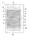
以上のように構成された枠体8、9によって集電部材3、4を保持してセパレータ13が構成され、セパレータ13と単位セル15を交互に積層して、燃料電池スタック100が構成される。図8は燃料電池スタック100の部分平面図である。燃料電池スタック100の上面には、多数の導入口43と流入開放口45が交互に開口し、この導入口43と流入開放口45に、後述するように、空気マニホールド54から空気が流入するとともに、ノズル55から噴射された水が同時に流入する。側壁47は、空気の流通経路に配置され冷却フィンとしても作用する。
導入口43と流入開放口45から流入した空気と水は、冷却流路41内で、潜熱冷却により集電部材3、4を冷却する。
【0026】
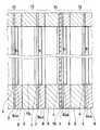
図9は、燃料電池スタック100の全体平面図である。以上のように構成された燃料電池セパレータ13は、所定の枚数重ねられたモジュール130(積層単位体)を構成し、このモジュール130を複数重ねることによって燃料電池スタック100が構成される。モジュール130とモジュール130の間には、図11に示されているように、集電部材3と集電部材4の間に遮蔽板16を挟んだ、セパレータ14が介在する。図12は、遮蔽板16の全体平面図である。遮蔽板16は、モジュール130の間に介挿された際に、水素通路17a又は水素通路17bのいずれかに対応した位置に、水素通路17a、17bの断面形状と同じ形状の、孔161a又は孔161bを備えている。孔161a又は孔161bは、1枚の遮蔽板16について、どちらか一方のみが形成されている。更には、図6に示されているセパレータ9を用いてもよい。この場合には、孔93a又は孔93bのいずれか一方を開孔しない事でも実現される。
なお、遮蔽板16は、導電性を有し、燃料電池スタック100内での電気の流通は妨げない。
【0027】
一方、遮蔽板16が孔161aを有する場合には、水素通路17bでの水素ガスの流通は、遮蔽板16によって遮断される。遮蔽板16が孔161bを有する場合には、水素通路17aでの水素ガスの流通は、遮蔽板16によって遮断される。遮蔽板16は、水素ガスが流入する側から流出する側へ配置されている順に、孔161bが設けられている遮蔽板16、孔161aが設けられている遮蔽板16・・・となるよう、交互に配置される。このようにモジュール130毎に、水素通路17aと水素通路17bの一方を交互に遮蔽することで、供給された水素ガスは、モジュール130単位で、連続して各燃料室30内を流通する。具体的には、最初のモジュール130では、水素通路17a(燃料流入通路)から水素通路17b(燃料流出通路)へ向けて、各燃料室30内を水素ガスが流れ、次のモジュール130では、水素通路17b(燃料流入通路)から水素通路17a(燃料流出通路)へ向けて、各燃料室30内を水素ガスが流れ、さらに次のモジュール130では、水素通路17aから水素通路17bへ向けて、各燃料室30内を連続して水素ガスが流れる・・・以降は、交互に水素ガスの流通方向が変化する。このように、水素通路17aと水素通路17bは、モジュール130の各燃料室30に水素ガスを供給する燃料流入通路と、各燃料室30から水素ガスが流出してくる燃料流入通路とに交互に入れ替わることとなる。
【0028】
燃料電池スタック100は、単位セル15とセパレータ13を積層して構成されたモジュール130と、モジュール130内において、セパレータ13の積層方向に形成され、燃料室30を挟んだ両側に位置し、各燃料室30にそれぞれ連通する一対の水素通路17a、17bとを有し、モジュール130を積層して構成されたものであって、隣接するモジュール130の間には、各モジュール130の一方の水素通路17a、17a(又は17b、17b)間を連通する連通部(孔161a(又は161b))と、他方の水素通路17b、17b(又は17a、17a)間の水素流通を遮断する遮断部162b(又は162a)とを有し、連通部と遮断部は、積層されているモジュール130の積層方向に向けて順に、一方の水素通路17a、17a(又は17b、17b)と他方の水素通路17b、17b(又は17a、17a)において交互に設けられ、一対の水素流路(17a、17b)間の各燃料室30内を流れる水素ガスの流通方向が、モジュール130毎に交互に逆向きに変化する構成となっている。
【0029】
このように、燃料電池スタック100を、複数のモジュール130に分割し、モジュール毎に水素ガスを流通させる構成とすることによって、各モジュール130の間で水素ガス流量に差が生じることを防止できる。また、1つのモジュール130内においても、積層方向に配置された各燃料室30間で水素ガス流量の差が生ずることを抑制できる。さらに、燃料電池スタック100に供給された水素ガスは、繰り返し、モジュール130内を流れるので、燃料室30の燃料極に接触する機会が増え、反応効率が向上する。1つのモジュール130が有する燃料室30の総和の容積は、大量の水素が流通可能となる程度に確保されるので、水素の供給速度を上げても(水素の流量を上げても)、水素がモジュール130内の燃料室30内に滞ることなく、短時間でジュール130外へ(即ち、燃料電池スタック100の外へ)流れ出ることができる。これにより、置換速度が増大することとなり(即ち、置換ガスが水素に入れ替わるまでに要する時間が短くなり)、置換ガスと水素ガスが、燃料室30内で偏在する時間を一層短縮することができ、電極の劣化を防止することができる。さらには、通常運転時においては、水素の流速が増大することで、生成水の排出を容易にし、燃料電池の水詰まりによる出力低下が防止できる。
【0030】
モジュール130を構成する燃料電池セパレータ13の枚数は、各セパレータ13における水素流路302の断面積(燃料室内を流れる水素ガスの流線に対して、垂直な面の面積が、最も小さくなる位置の面積:図10におけるa部分の面積の総和(モジュール130を構成するセパレータ13の、前記水素流路302断面積の総和)、又は、水素流通経路84の横断面積の総和(図11の太実線で囲まれたb部分の面積))が、水素通路17a、17bの横断面積とほぼ同じとなる枚数に決められる。このような構成とすると、燃料電池スタック100内を流れる水素ガスの流通経路の横断面積が、燃料電池スタック100にガスが流入してから流出するまで、大きく変動せず、モジュール130を構成する各セパレータ13の燃料室30に、ガス流をより均一に分配することができる。さらに、燃料室30内にガス滞留部が起きることが抑制される。
【0031】
このため、始動時のガス供給の際にも、始動時に充填されているガス(空気)を効率よく排出し、一層均一かつ迅速に水素ガスに置換することが可能となる。
【0032】
図9に示されているように、燃料電池スタック100の両端には、端部セパレータの外側に電極板191a、191bが積層され、さらに外側には、絶縁部材192a、192b、エンドプレート19a、19bの順に積層されている。
【0033】
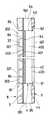
図13は、燃料電池スタック100の正面図である。エンドプレート19aの外側面には凹部193aが形成されている。この凹部193aの端部には、水素通路17aに連通する燃料供給口182aが開口している。凹部193aには、カバー194aが、全体に覆い被せられている。凹部193aは、水素通路17aへ向けて幅広となる形状に形成されている。カバー194aは、凹部193aの形状に沿った形状に形成され、水素通路17aに対して反対側の端に、ガス導入口181aが形成されている。カバー194aと凹部193aで画成された空間によって、整流手段としての導入案内路18aが構成されている。この整流手段は、水素導入路202から送られてくる水素ガスを水素通路17aへ滑らかに導く作用を有し、流通経路の断面形状や流通方向が急激に変化することによって生じる抵抗や乱流の発生を抑制し、その結果、燃料電池スタック100内の各燃料室に均一に水素ガスが供給されるように構成されている。
【0034】
この導入案内路18aは、ガス導入口181aが、水素導入路202と同じ断面形状を有し、燃料供給口182aが、水素通路17aと同じ断面形状を有している。そして、ガス導入口181aから燃料供給口182aまでの流路183aは、横断面の幅が漸増し、ガス流の圧力損失を抑制しつつ、水素ガスを導く構成となっている。また、流路183aには、水素通路17aの横断面におけるガス流速の分布が均一となるように、ガス流を案内する整流板184aが設けられている。
【0035】
図14は、燃料電池スタック100の背面図である。燃料電池スタック100の水素ガス流出部分には、導出案内路18bが設けられている。導出案内路18bは、エンドプレート19bの外側面に形成された凹部193bと、この凹部193bに被せられたカバー194bとによって画成された空間によって構成される。凹部193bの端部には、水素通路17aに連通する燃料排出口181bが開口している。
【0036】
この導出案内路18bは、燃料排出口181bが、水素通路17aと同じ断面形状を有し、ガス導出口182bが、水素導出路203と同じ断面形状を有している。そして、燃料排出口181bからガス導出口182bまでの流路183bは、横断面の幅が漸減し、さらに、流路183aには、整流板184aが設けられ、ガス流の圧力損失を抑制しつつ、水素ガスを導く構成となっている。
【0037】
以上のような燃料電池スタック100の構成によって、燃料電池スタック100に流入した水素ガスは、圧力損失が抑制され、各燃料電池セパレータ13の燃料室30へ均一に水素ガスが供給される。なお、ガス導出口182bは、燃料排出口181bの下端部の位置よりも、鉛直方向において、同じ高さ、又は下方に位置している。このような位置にガス導出口182bを設けることによって、燃料電池スタック100から、水素通路17aを通って排出される水を、水素導出路203へ排出することが容易となる。
【0038】
次に、図1に示されている他の構成について説明する。空気供給系12は大気から空気を燃料電池スタック100の開口941を介して空気流路40と冷却流路41に供給し、燃料電池スタック100から排出された空気を水凝縮器51を通過させて排気する。空気供給路123には、吸気手段としての空気ファン122が備えられ、フィルタ121を介して、大気から空気を空気マニホールド54へ送る。空気はマニホールド54から燃料電池スタック100の空気流路40へ流入して空気極3へ酸素を供給する。燃料電池スタック100から排出された空気は、空気排気マニホールドを経て、水凝縮器51で排気空気中の水分が凝縮・回収されて大気へ放出される。燃料電池スタック100から排出される温度は排気温度センサS1によりモニタされている。また、燃料電池スタック100には、燃料電池スタック100を構成する単位セル毎に電極の局部電位を測定する電位検出センサS2が設けられている。
【0039】
この実施形態では、空気マニホールド54にノズル55が配設されており、これより吸気中に水が液体の状態で噴射され、空気に混合される。この水の大部分は液体の状態を維持したまま、燃料電池スタック100の下側に設けられた、容器内に回収され、水回収ポンプ62により水タンク53に送られる。
【0040】
燃料供給系10は、水素導通路201、水素導入路202を介して、高圧水素タンク11から放出された水素を燃料電池スタック100の水素通路17aへ送る。水素導通路201には、高圧水素タンク11側から燃料電池スタック100側へ向けて、水素元弁22、水素一次圧センサS3、水素一次圧調圧弁21、水素二次圧可変調圧弁72a、水素供給電磁弁24、水素二次圧センサS4が、この順に設けられている。水素一次圧センサS3によって高圧水素タンク11側の水素圧がモニタされている。
【0041】
水素二次圧調圧弁72aには、これに並列に回路が設けられている。その回路は、両端が水素二次圧調圧弁72aの上流側と下流側とに接続された流路71と、流路71において起動時水素供給電磁弁73を備えている。二次圧調圧弁72aの設定値は、約0.1MPaとなっている。即ち、二次圧調圧弁72aの設定値は、通常運転時の水素供給圧である。起動時においては、起動時水素供給電磁弁73が開放される。
【0042】
水素調圧弁21によって、燃料電池スタック100へ供給するために適した圧力に調整される。また水素供給電磁弁22の開閉によって、水素の燃料電池スタック100への供給が電気的に制御され、水素ガスの供給を行わない場合には、この電磁弁22が閉じられ、水素ガスの供給が止められる。また、水素二次圧センサS4によって、燃料電池スタック100に供給される直前の水素ガス圧がモニタされる。
【0043】
水素導通路201には、水素導入路202の一端が接続され、水素導入路202の他端は燃料電池スタック100の水素通路17aに接続されている。また、水素導入路202には、安全弁が設けられており、導入路内のガス圧が所定の値以上となった場合には、この安全弁が開放され、導入路202内(ひいては、燃料電池スタック100内)の圧力が下げられる。
【0044】
燃料電池スタック100では、各モジュール130単位で水素ガスが流通し、図3に示されているように、一方の水素通路17a(又は17b)から水素ガスが水素流通経路84a(又は84b)へ流入し、さらに、水素流通経路84a(又は84b)から水素流路301、302へ流入する。水素流路301、302において、燃料極へ水素が供給され、残った水素ガスは、水素流通経路84b(又は84a)から水素通路17b(又は17a)へ流入する。
【0045】
燃料供給系10において、燃料電池スタック100の水素通路17aから排出される水素ガスは水素導出路203へ排出される。水素導出路203には、酸素濃度センサS5と、水素濃度センサS6と、ポンプ25が設けられ、ポンプ25は、燃料電池スタック100から水素ガスを吸引する方向に駆動する。ポンプ25の下流側には、水素返還路205の一端が接続されている。水素返還路205には、電磁弁29が設けられ、高圧水素タンク11から供給される水素ガスが、直接排出側に流出しない構成となっている。
【0046】
水素返還路205の他端は、水素導入路202に接続され、水素導入路202、水素導出路203、水素返還路205によって、水素循環路が形成されている。電磁弁29とポンプ25の間には、水素排出路204の一端が水回収トラップ23を介して接続されている。水素排出路204には、逆止弁26、水素排出電磁弁27a、消音器28aが、この順で設けられている。
【0047】
酸素濃度センサS5は、燃料電池スタック100から排出されたガスの酸素濃度を検出し、水素濃度センサS6は、燃料電池スタック100から排出されたガスの水素濃度を検出する。起動時排出回路205は、一端がポンプ25の上流側に、他端が水素排出路204の逆止弁26の上流側に接続されている。この起動時排出回路205には、起動専用排気弁74が設けられている。起動時には、起動専用排気弁74が開放され、ポンプ25を経ずに、ガスが直接水素排出路204へ導かれる。起動の際のガス充填時に、排出口でのガス流抵抗を抑え、起動時の水素流入速度を増大させ、水素ガスへの置換速度を増大(置換時間を短縮)すさせるためである。
【0048】
タンク53の水は水供給ポンプ61により、水供給路56を介して、空気マニホールド54内に配設されたノズル55へ圧送され、ここから空気マニホールド54内で連続的若しくは間欠的に噴出される。この水は燃料電池スタック100の開口941を介して空気流路40と冷却流路41に送られる。ここにおいて優先的に水分から潜熱を奪うので、酸素極15b側の電解質膜15aからの水分の蒸発が防止される。従って、電解質膜15aはその酸素極15b側で乾燥することなく、生成水により常に均一な湿潤状態を維持する。また、酸素極15bの表面に供給された水は酸素極15b自体からも熱を奪いこれを冷却し、さらに冷却流路41に流入した水も熱を奪う。これにより燃料電池スタック100の温度を制御できる。
【0049】
即ち、燃料電池スタック100へ特に冷却水系を付加しなくても当該燃料電池スタック100を充分に冷却することができる。なお、排気温度センサS1で検出された排出空気の温度に対応して水供給ポンプ61の出力を制御し、燃料電池スタック100の温度を所望の温度に維持することもできる。
タンク53の水は、空気マニホールド54内に配設されたノズル55から酸素極15bの表面に供給され、この水は、水凝縮器51で回収され、容器にためられた水とともに、水回収ポンプ62により、タンク53に回収される。ポンプ62とタンク53の間には、タンク53から水回収ポンプ62への水の逆流を防止するため、逆止弁52が設けられている。タンク53の水量は、水位センサS7によって検出される。
【0050】
以上のような構成において、燃料電池システム1により電力出力される通常運転状態では、空気ファン122から燃料電池スタック100に空気が供給され、同時に、燃料供給系10からは水素ガスが燃料電池スタック100に供給される。そして、燃料電池スタック100内では、発電反応が継続され、電力と、反応により生成された生成水が発生する。このような発電反応は、酸素極に空気を、燃料極に水素ガスを継続して供給することにより維持される。このような通常運転時においては、水素ガスの消費効率を考慮して、単位セル15において反応が可能な充分の濃度の水素ガスが供給され、通常運転時の供給圧力は、充分な反応が維持でき、無駄が生じない範囲で設定されている。通常運転時の供給圧力が必要以上に高いと、供給過剰となり、反応していない多くの水素が排出され、燃料ガスの無駄が発生する。さらに、あまり供給圧力を上げ過ぎると固体電解質膜の破損につながる。このような観点から、通常運転時の水素ガスの供給ガス圧は、例えば、0.1メガパスカルに設定されている。一方起動時に水素ガスを供給する場合の供給ガス圧は、置換ガスの排出と、ガス偏在抑制を目的とするため、上記通常運転時のガス圧に比べて高い、つまり1次水素調圧弁21で調整された圧力で供給される。またこの際、供給時間は微小時間に設定され、固体電解質膜がガス圧によって破損されない程度の時間であり、かつガスの偏在が十分抑制される時間となっている。
【0051】
上記説明した燃料電池システム1は、制御部によって、各部が制御される。また、各センサS1〜S7の検出値は、制御部に供給される。具体的には、制御部によって、水供給ポンプ61による供給量が制御され、水回収ポンプ62のオン・オフと、空気ファン122のオン・オフ、水素ポンプ25のオン・オフが制御される。さらに、制御部によって、水素元弁22の開閉、水素供給電磁弁24の開閉、水素排出電磁弁27aの開閉、電磁弁29開閉について制御される。
【0052】
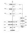
以上のような構成を有する燃料電池システム1は、起動時において、以下のような動作を行う。図15及び図16は、第1実施形態における燃料電池システム1の起動時における燃料供給系10の制御動作を示すフローチャートである。
【0053】
水素元弁22は開放されていることを前提とし、イグニッションONなど、起動を始める動作が確認される(ステップS101)。次に、センサ類やポンプなどの補機類の動作をチェックする(ステップS103)。このような動作チェックによって、システム各部の検出値を取得することが可能となる。さらに、空気供給系12、水供給系50の作動を開始する(ステップS105)。つまり、空気ファン122を駆動させ、ポンプ61を駆動させる。水素一次圧センサS3から供給された検出値に基づいて、水素一次圧が極端に低くないか確認する(ステップS107)。圧力が低いと、ガス供給時に十分な流速が得られず、置換ガス(例えば、空気)を、パージすることができないからである。
【0054】
次に、水素ガスを導入して、置換ガスを排出する動作を開始する。排気側のガス流路を閉じたまま、高圧のガスを供給すると、燃料電池スタック100が損傷する恐れがあるので、最初に排気弁27aを開放し(ステップS109)、次に起動専用排気弁74を開放する(ステップS111)。
【0055】
そして、起動用水素供給弁113を開放し(ステップS113)、さらに水素供給弁24を開放する(ステップS115)。これにより、1次水素調圧弁21で調圧された水素ガスが、起動用水素供給回路を経て、2次水素調圧弁72aで調圧されずに、直接燃料電池スタック100へ供給される。
【0056】
燃料電池スタック100から排出されたガスを水素濃度センサS6で検出した検出値に基づき、排出ガスの水素濃度が95%以上であるか判断する(ステップS117)。水素濃度が95%に達しない場合には、電極が劣化する恐れがあるので、警告灯を点灯させる(ステップS123)。排出ガスの水素濃度が95%以上であれば、燃料室30内は、ほぼ水素ガスで満たされ、ガスの偏在が発生していない、或いは局部電流か発生するほど酸素ガスが残っていないと推測することができる。
【0057】
酸素濃度センサS5の検出値に基づき、排出ガスの酸素濃度が1%以下であるか判断する(ステップS119)。酸素濃度が1%以下でない場合には、電極が劣化する恐れがあるので、警告灯を点灯させる(ステップS123)。排出ガスの酸素濃度が1%以下であれば、燃料室30内は、酸素ガスがほとんど残っておらず、ガスの偏在が発生していない、或いは局部電流か発生するほど酸素ガスが残っていないと推測することができる。
【0058】
酸素濃度が1%以下である場合には、電位検出センサS2の検出値に基づき、全ての単位セル電極の局部電位が1.1V以下であるか判断する(ステップS121)。1つの単位セルであっても、局部電位が1.1Vより大きいものがある場合には、電極が劣化する恐れがあるので、警告灯を点灯させる(ステップS123)。排出ガスの水素ガス濃度を検出するだけでは、各燃料室毎のガス偏在の程度は判明しないので、各燃料室毎の局部電位を検出することで、ガス偏在の可能性を判定する。
【0059】
ステップS121において、電極の局部電位が1.1V以下であると判断された場合には、排出ガスの水素濃度が95%以上であり、かつ排出ガスの酸素濃度が1%以下であり、かつ全ての電極の局部電位が1.1V以下であることを意味する。この場合には、各燃料室30内がほぼ均一に水素ガスに置換されたことを意味するので、起動時水素供給電磁弁73を閉じる(ステップS125)。これにより、二次圧調圧弁72aに水素ガスが供給され、燃料電池スタック100へは、通常運転時の圧力に調整された水素ガスが供給される。
【0060】
起動用水素排気弁74を閉じる(ステップS127)。供給されるガス圧が通常運転時のガス圧となった為、通常運転状態に回路の各部が切り換えられる。
【0061】
排気弁27aが閉じられる(ステップS129)。これにより、通常運転状態に移行する(ステップS131)。排気弁27aは、通常運転時においては、水素濃度を一定値以上に維持するために、適宜開閉される。以上のような動作によって、置換ガスは、短時間で、かつ確実に排出され、水素ガスに交換される。
【0062】
ステップS123で警告灯を点灯させた後、電極が劣化を防止するため、非常停止動作を実行する(ステップS124)。即ち、排気弁27aを閉じ、起動専用排気弁74を閉じ、起動用水素供給弁113を閉じ、水素供給弁24を閉じる。更に、次に、ステップS103でチェックした補機類を停止し(ステップS126)、イグニッションオフにより(ステップS128)、車両システムを停止する(ステップS130)。
【0063】
上記実施形態の他、燃料電池スタック100を構成する各モジュール130の燃料室容積の総和を、燃料ガスが流れる方向に沿って、順に変化する構成することができる。例えば、燃料ガスが流入する側のモジュール130の燃料室容積が最小で、ガスが流出側のモジュール130の燃料室容積が最大となり、その間に配置されている各モジュール130の燃料室容積の総和は、燃料ガスが流れる方向に沿って順に大きくなる構成とすることができる。燃料室には、酸素極から固体電解質膜を通じて逆拡散により生成される生成水が溜まるため、燃料電池スタック100内を燃料ガスが流れると、ガス流によって生成水が押し流され、下流側のモジュール130の燃料室へ向けて生成水が増えて行き、下流側の燃料室内により多くの水が溜まることとなる。これによって、燃料ガスと燃料極との接触が妨げられるため、反応が抑制される恐れがある。しかし、下流側の燃料室の容積を大きく取れば、水によって損なわれた容積を確保することができ、反応を確実に確保することができる。
【0064】
一方、逆に燃料ガスが流入する側のモジュール130の燃料室容積が最大で、ガスが流出側のモジュール130の燃料室容積が最小となり、その間に配置されている各モジュール130の燃料室容積の総和は、燃料ガスが流れる方向に沿って順に小さくなる構成とすることができる。この場合には、容積が順に狭くなることによって、ガス流の流速が増し、生成水が溜まる下流側のモジュール130で特にガス流速が大きくなる。このため、燃料室内に溜まった水は、ガス流により吹き飛ばされ、水の排出が容易となる。
【0065】
このように、積層単位体の燃料室容積の総和を変化させるには、例えば、モジュール130を構成する、単位セル15とセパレータ13の枚数を変えることにより実現できる。つまり、燃料室容積の総和を増やすには、積層される単位セル15とセパレータ13の枚数を増やし、燃料室容積の総和を減らすには、積層される単位セル15とセパレータ13の枚数を減らせばよい。また、水の排出を容易とするために、燃料電池スタック100の設置姿勢を、鉛直方向において、ガス排出側(エンドプレート19b側)を低く、ガス供給側(エンドプレート19a側)を高く設定することができる。
【0066】
さらに、遮蔽板16によって、水素流路17a、17bを塞ぎ、モジュール130毎にガスが通過する構成としたが、2つの枠体8、9の少なくとも一方において、水素流路17a、17bを構成するためにそれぞれ設けられた一対の孔82a82b及び孔93a93bについて、一方の孔を塞いだ枠体8、9を、遮蔽板16に代えて設けることによって、作用を備えたモジュールを構成することができる。
【0067】
【発明の効果】
請求項1に記載の発明によれば、燃料電池スタックを構成する積層単位体毎に、起動時ガスが流通するので、置換ガスとの間でガス偏在が発生することが抑制される。また、置換ガスを燃料ガスに代えまでの供給時間が短縮され、この燃料電池スタックを備えたシステム始動までの時間が短縮される。また、起動の際のガス充填時に、排出口でのガス流抵抗を抑え、起動時の水素流入速度を増大させ、水素ガスへの置換速度を増大(置換時間を短縮)させることができる。
【0069】
請求項2に記載の発明によれば、積層される孔によって燃料流通路を構成し、遮蔽板により燃料ガスの流通を規制する構成としたので、製造が容易である。また、起動の際のガス充填時に、排出口でのガス流抵抗を抑え、起動時の水素流入速度を増大させ、水素ガスへの置換速度を増大(置換時間を短縮)させることができる。
【図面の簡単な説明】
【図1】この発明の燃料電池システム1を示すブロック図である。
【図2】燃料電池用セパレータを示す全体正面図である。
【図3】燃料電池セパレータで構成された燃料電池スタックの部分断面平面図(A‐A断面図)である。
【図4】燃料電池セパレータで構成された燃料電池スタックの部分断面側面図(B‐B断面図)でである。
【図5】燃料電池セパレータの部分断面側面図(C‐C断面図)である。
【図6】燃料電池用セパレータの全体背面図である。
【図7】単位セルの断面図である。
【図8】燃料電池スタックの部分平面図である。
【図9】燃料電池スタックの全体平面図である。
【図10】燃料電池スタックの部分断面側面図である。
【図11】水素通路の縦断面を示す燃料電池スタックの部分断面図(D-D断面図)である。
【図12】遮蔽板の全体平面図である。
【図13】燃料電池スタックの全体正面図である。
【図14】燃料電池スタックの全体背面図である。
【図15】第1実施形態における起動時制御動作を示すフローチャートである。
【図16】第1実施形態における起動時制御動作を示すフローチャートである。
【符号の説明】
1 燃料電池システム
100 燃料電池スタック
13 燃料電池セパレータ
130 モジュール
15 単位セル
17a、17b 水素通路
3 集電部材
30 燃料室
32 柱状凸部
301 水素流路
302 水素流路
4 集電部材
40 空気流路
41 冷却流路
42 凸状部
43 導入口
44 導出口
45 流入開放口
46 流出開放口
8 枠体
9 枠体[0001]
BACKGROUND OF THE INVENTION
The present invention relates to a fuel cell system, and more particularly, to a fuel cell system capable of supplying a large amount of fuel gas in a short time at startup.
[0002]
[Prior art]
Conventionally, in a fuel cell using a polymer electrolyte membrane, fuel gas or oxidizing gas is ionized on both sides of the electrolyte membrane, and the ions pass through the electrolyte membrane to cause an electrochemical reaction. If fuel gas and oxidizing gas are present with the electrolyte membrane in between, the electrochemical reaction between the two continues. Therefore, conventionally, in order to stop the operation of the fuel cell, the supply of the fuel gas and the oxidizing gas to the fuel cell is stopped, and the fuel electrode side is replaced with air or nitrogen instead of the fuel gas. A configuration is adopted in which gas is sent in and no reaction occurs after stopping.
And at the time of driving | operation start, the structure which discharges substitution gas outside and starts reaction by sending fuel gas into a fuel chamber is taken.
[0003]
On the other hand, as described in Japanese Patent Application Laid-Open No. 11-26003, in the fuel chamber, a region where the concentration of the fuel gas is particularly denser than other regions and a region where the concentration of the oxidizing gas is particularly denser than other regions coexist. That is, when a state where the fuel gas and the oxidizing gas are unevenly distributed in the same fuel chamber occurs, the portion where the fuel gas is unevenly formed forms a local battery, and the current where the oxidizing gas is unevenly distributed is opposite to that during normal power generation. In particular, the oxygen electrode is corroded and the oxygen electrode or the electrolyte membrane is rapidly deteriorated.
Examples of the configuration for purging the residual fuel gas in the fuel chamber include the following documents.
[0004]
[Patent Document 1]
Japanese Patent Laid-Open No. 02-33866.
[0005]
[Problems to be solved by the invention]
In
[0006]
Further, when the fuel electrode gas is replaced with air in the stop state, when the fuel gas is supplied at the time of startup, the fuel gas and the air are momentarily unevenly distributed in the fuel chamber. Due to this uneven distribution, there has been a problem that an electrochemical reaction occurs, which causes deterioration of the electrode.
An object of this invention is to provide the fuel cell system which can suppress deterioration of an electrode.
[0007]
[Means for Solving the Problems]
The above object is achieved by the present invention described below.
(1) A fuel holding portion formed by alternately laminating a plurality of unit cells and a plurality of separators and formed between the fuel electrode of each unit cell and the separator, and a fuel communicating with each fuel holding portion. A plurality of stacked unit bodies each having an inflow passage and a fuel outflow passage communicating with each fuel holding portion,
Each stack unit has a fuel inflow passage connected to a fuel inflow passage of a stack unit adjacent to the downstream side of the fuel gas, and a fuel inflow passage to a fuel outflow passage of the stack unit adjacent to the upstream side of the fuel gas. ,
A fuel supply port is provided in the fuel inflow passage of the stack unit located at the most upstream side of the fuel gas, and a fuel discharge port is provided in the fuel outflow passage of the stack unit located at the most downstream side. Fuel cell stackWhen,
A fuel gas circuit having one end connected to the fuel supply port and the other end connected to the fuel discharge port;
A pump provided in the fuel gas circulation path for sucking and circulating fuel gas from the fuel outlet side;
A fuel gas communication path connected to the fuel gas circulation path and sending fuel gas to the fuel supply port via the fuel gas circulation path;
A fuel gas supply valve for starting that is provided in the fuel gas conduction path and supplies fuel gas at a pressure higher than the gas pressure during normal operation when opened;
A start-up discharge circuit in which one end is connected between the pump and the fuel discharge port and the other end is connected to the fuel gas discharge path;
A start-up fuel gas exhaust valve provided in the start-up discharge circuit;
The starting fuel gas exhaust valve and the starting fuel gas supply valve are opened only during the period from the start to the transition to the normal operation state.
[0009]
(2) A fuel cell stack configured by alternately stacking unit cells and separators,
A fuel holding part formed between the fuel electrode of each unit cell and the separator;
Lamination of the unit cell and the separatorTwo fuel flow passages provided along the direction and communicating with the respective fuel holding portions,
One fuel flow passage is provided with a fuel supply port, and the other fuel flow passage is provided with a fuel discharge port.
The fuel flow passage is formed by laminating holes formed at positions where each unit cell and the separator overlap each other when they are laminated,
A shielding plate having a hole at a position corresponding to one fuel flow passage and having no hole at a position corresponding to the other fuel flow passage is inserted at predetermined intervals by alternately changing the positions of the holes. Fuel cell stackWhen,
A fuel gas circuit having one end connected to the fuel supply port and the other end connected to the fuel discharge port;
A pump provided in the fuel gas circulation path for sucking and circulating fuel gas from the fuel outlet side;
A fuel gas conduction path connected to the fuel gas circulation path and sending fuel gas to the fuel supply port via the fuel gas circulation path;
A fuel gas supply valve for starting that is provided in the fuel gas conduction path and supplies fuel gas at a pressure higher than the gas pressure during normal operation when opened;
A start-up discharge circuit in which one end is connected between the pump and the fuel discharge port and the other end is connected to the fuel gas discharge path;
A start-up fuel gas exhaust valve provided in the start-up discharge circuit;
The starting fuel gas exhaust valve and the starting fuel gas supply valve are opened only during the period from the start to the transition to the normal operation state.
[0013]
DETAILED DESCRIPTION OF THE INVENTION
Next, a preferred embodiment of the present invention will be described. This embodiment is a fuel cell system mounted on an electric vehicle. FIG. 1 is a block diagram showing a
[0014]
The configuration of the
[0015]
The
The
[0016]
The
[0017]
The
[0018]
The
As shown in FIGS. 3 and 5, the
[0019]
The opening on one end side of the
[0020]
A
[0021]
The
[0022]
The upstream
In addition, a concave portion having a contour formed along the
[0023]
FIG. 7 is an enlarged cross-sectional view of the
[0024]
The inner walls of the
[0025]
The
The air and water flowing in from the
[0026]
FIG. 9 is an overall plan view of the
Note that the shielding
[0027]
On the other hand, when the shielding
[0028]
The
[0029]
As described above, by dividing the
[0030]
The number of
[0031]
For this reason, even when the gas is supplied at the time of starting, the gas (air) filled at the time of starting can be discharged efficiently and replaced with hydrogen gas more uniformly and quickly.
[0032]
As shown in FIG. 9,
[0033]
FIG. 13 is a front view of the
[0034]
In the
[0035]
FIG. 14 is a rear view of the
[0036]
In the lead-
[0037]
With the configuration of the
[0038]
Next, another configuration shown in FIG. 1 will be described. The
[0039]
In this embodiment, a
[0040]
The
[0041]
The hydrogen secondary
[0042]
The pressure is adjusted to be suitable for supplying to the
[0043]
One end of a
[0044]
In the
[0045]
In the
[0046]
The other end of the
[0047]
The oxygen concentration sensor S5 detects the oxygen concentration of the gas discharged from the
[0048]
Water in the
[0049]
That is, the
Water in the
[0050]
In the above-described configuration, in a normal operation state where power is output from the
[0051]
In the
[0052]
The
[0053]
On the premise that the
[0054]
Next, the operation of introducing hydrogen gas and discharging the replacement gas is started. If high-pressure gas is supplied while the exhaust-side gas flow path is closed, the
[0055]
Then, the startup hydrogen supply valve 113 is opened (step S113), and the
[0056]
Based on the detection value of the gas discharged from the
[0057]
Based on the detection value of the oxygen concentration sensor S5, it is determined whether the oxygen concentration of the exhaust gas is 1% or less (step S119). If the oxygen concentration is not 1% or less, the warning lamp is turned on because the electrode may be deteriorated (step S123). If the oxygen concentration of the exhaust gas is 1% or less, there is almost no oxygen gas remaining in the
[0058]
When the oxygen concentration is 1% or less, it is determined whether the local potentials of all the unit cell electrodes are 1.1 V or less based on the detection value of the potential detection sensor S2 (step S121). Even if there is one unit cell having a local potential larger than 1.1 V, the electrode may be deteriorated, so that a warning lamp is turned on (step S123). By detecting only the hydrogen gas concentration of the exhaust gas, the degree of gas uneven distribution for each fuel chamber cannot be determined. Therefore, the possibility of gas uneven distribution is determined by detecting the local potential for each fuel chamber.
[0059]
If it is determined in step S121 that the local potential of the electrode is 1.1 V or less, the hydrogen concentration of the exhaust gas is 95% or more, the oxygen concentration of the exhaust gas is 1% or less, and all This means that the local potential of the electrode is 1.1V or less. In this case, it means that the inside of each
[0060]
The start-up
[0061]
The
[0062]
After turning on the warning lamp in step S123, an emergency stop operation is performed to prevent the electrode from deteriorating (step S124). That is, the
[0063]
In addition to the above embodiment, the total sum of the fuel chamber volumes of the
[0064]
On the other hand, the fuel chamber volume of the
[0065]
Thus, changing the total sum of the fuel chamber volumes of the stacked unit bodies can be realized by changing the number of
[0066]
Further, the
[0067]
【The invention's effect】
According to the first aspect of the present invention, since the startup gas flows through each of the stacked unit bodies constituting the fuel cell stack, occurrence of gas uneven distribution with the replacement gas is suppressed. Further, the supply time until the replacement gas is replaced with the fuel gas is shortened, and the time until the system starting with the fuel cell stack is shortened.In addition, the gas flow resistance at the discharge port can be suppressed at the time of gas filling at the time of start-up, the hydrogen inflow speed at the time of start-up can be increased, and the replacement speed with hydrogen gas can be increased (replacement time is shortened).
[0069]
Claim2According to the invention described in (1), the fuel flow passage is configured by the stacked holes, and the flow of the fuel gas is regulated by the shielding plate. Therefore, the manufacturing is easy.In addition, the gas flow resistance at the discharge port can be suppressed at the time of gas filling at the time of start-up, the hydrogen inflow speed at the time of start-up can be increased, and the replacement speed with hydrogen gas can be increased (replacement time is shortened).
[Brief description of the drawings]
FIG. 1 is a block diagram showing a
FIG. 2 is an overall front view showing a fuel cell separator.
FIG. 3 is a partial cross-sectional plan view (AA cross-sectional view) of a fuel cell stack including a fuel cell separator.
FIG. 4 is a partial cross-sectional side view (BB cross-sectional view) of a fuel cell stack including a fuel cell separator.
FIG. 5 is a partial cross-sectional side view (CC cross-sectional view) of a fuel cell separator.
FIG. 6 is an overall rear view of a fuel cell separator.
FIG. 7 is a cross-sectional view of a unit cell.
FIG. 8 is a partial plan view of a fuel cell stack.
FIG. 9 is an overall plan view of a fuel cell stack.
FIG. 10 is a partial cross-sectional side view of a fuel cell stack.
FIG. 11 is a partial cross-sectional view (DD cross-sectional view) of the fuel cell stack showing a vertical cross-section of a hydrogen passage.
FIG. 12 is an overall plan view of a shielding plate.
FIG. 13 is an overall front view of a fuel cell stack.
FIG. 14 is an overall rear view of the fuel cell stack.
FIG. 15 is a flowchart showing a startup control operation in the first embodiment.
FIG. 16 is a flowchart showing a startup control operation in the first embodiment.
[Explanation of symbols]
1 Fuel cell system
100 Fuel cell stack
13 Fuel cell separator
130 modules
15 unit cells
17a, 17b Hydrogen passage
3 Current collector
30 Fuel chamber
32 Columnar convex part
301 Hydrogen flow path
302 Hydrogen flow path
4 Current collector
40 Air flow path
41 Cooling channel
42 Convex part
43 Introduction
44 Outlet
45 Inflow opening
46 Outflow opening
8 Frame
9 Frame
Claims (2)
Translated fromJapanese各積層単位体は、燃料ガスの下流側に隣接する積層単位体の燃料流入通路に燃料流出通路が、燃料ガスの上流側に隣接する積層単位体の燃料流出通路に燃料流入通路がそれぞれ連通され、
燃料ガスの最も上流に位置している積層単位体の燃料流入通路には、燃料供給口が、最も下流に位置している積層単位体の燃料流出通路には、燃料排出口が設けられている燃料電池スタックと、
一端が前記燃料供給口に接続され、他端が前記燃料排出口に接続された燃料ガス循環路と、
前記燃料ガス循環路に設けられ、前記燃料排出口側から燃料ガスを吸引して循環させるポンプと、
前記燃料ガス循環路に接続され、前記燃料ガス循環路を介して前記燃料供給口へ燃料ガスを送る燃料ガス導通路と、
前記燃料ガス導通路に設けられ、開放時に通常運転時のガス圧に比べて高い圧力で燃料ガスを供給する起動用燃料ガス供給弁と、
一端がポンプと燃料排出口の間に接続され、他端が燃料ガス排出路に接続されている起動時排出回路と、
前記起動時排出回路に設けられた起動用燃料ガス排気弁と、
前記起動用燃料ガス排気弁と起動用燃料ガス供給弁とは、起動時から通常運転状態に移行するまでの間のみ開放されることを特徴とする燃料電池システム。A plurality of unit cells and a plurality of separators alternately stacked, a fuel holding portion formed between the fuel electrode of each unit cell and the separator, and a fuel inflow passage communicating with each fuel holding portion, A plurality of stacked unit bodies each provided with a fuel outflow passage communicating with each fuel holding portion,
In each stacked unit body, a fuel outflow passage is connected to a fuel inflow passage of a stacked unit body adjacent to the downstream side of the fuel gas, and a fuel inflow passage is connected to a fuel outflow passage of the stacked unit body adjacent to the upstream side of the fuel gas. ,
A fuel supply port is provided in the fuel inflow passage of the stack unit located at the most upstream side of the fuel gas, and a fuel discharge port is provided in the fuel outflow passage of the stack unit located at the most downstream side. A fuel cell stack;
A fuel gas circuit having one end connected to the fuel supply port and the other end connected to the fuel discharge port;
A pump provided in the fuel gas circulation path for sucking and circulating fuel gas from the fuel outlet side;
A fuel gas conduction path connected to the fuel gas circulation path and sending fuel gas to the fuel supply port via the fuel gas circulation path;
A fuel gas supply valve for starting that is provided in the fuel gas conduction path and supplies fuel gas at a pressure higher than the gas pressure during normal operation when opened;
A start-up discharge circuit in which one end is connected between the pump and the fuel discharge port and the other end is connected to the fuel gas discharge path;
A start-up fuel gas exhaust valve provided in the start-up discharge circuit;
The starting fuel gas exhaust valve and the starting fuel gas supply valve are opened only during the period from the start to the transition to the normal operation state .
各単位セルの燃料極とセパレータとの間に形成された燃料保持部と、
前記単位セルと前記セパレータの積層方向に沿って設けられ、各燃料保持部にそれぞれ連通する2つの燃料流通路を有し、
一方の燃料流通路には燃料供給口が、他方の燃料流通路には燃料排出口が設けられており、
燃料流通路は、各単位セルとセパレータが積層された際に相互に重なり合う位置に形成された孔を積層することで形成され、
一方の燃料流通路に対応した位置に孔を有し、他方の燃料流通路に対応した位置に孔を有さない遮蔽板が、孔の位置を交互に変えて所定間隔で介挿されている燃料電池スタックと、
一端が前記燃料供給口に接続され、他端が前記燃料排出口に接続された燃料ガス循環路と、
前記燃料ガス循環路に設けられ、前記燃料排出口側から燃料ガスを吸引して循環させるポンプと、
前記燃料ガス循環路に接続され、前記燃料ガス循環路を介して前記燃料供給口へ燃料ガスを送る燃料ガス導通路と、
前記燃料ガス導通路に設けられ、開放時に通常運転時のガス圧に比べて高い圧力で燃料ガスを供給する起動用燃料ガス供給弁と、
一端がポンプと燃料排出口の間に接続され、他端が燃料ガス排出路に接続されている起動時排出回路と、
前記起動時排出回路に設けられた起動用燃料ガス排気弁と、
前記起動用燃料ガス排気弁と起動用燃料ガス供給弁とは、起動時から通常運転状態に移行するまでの間のみ開放されることを特徴とする燃料電池システム。A fuel cell stack configured by alternately stacking unit cells and separators,
A fuel holding part formed between the fuel electrode of each unit cell and the separator;
Provided alongthe stacking direction ofthe unit cell and the separator, and has two fuel flow passages communicating with the respective fuel holding portions,
One fuel flow passage is provided with a fuel supply port, and the other fuel flow passage is provided with a fuel discharge port.
The fuel flow passage is formed by laminating holes formed at positions where each unit cell and the separator overlap each other when they are laminated,
A shielding plate having a hole at a position corresponding to one fuel flow path and not having a hole at a position corresponding to the other fuel flow path is inserted at predetermined intervals by alternately changing the positions of the holes. A fuel cell stack;
A fuel gas circuit having one end connected to the fuel supply port and the other end connected to the fuel discharge port;
A pump provided in the fuel gas circulation path for sucking and circulating fuel gas from the fuel outlet side;
A fuel gas conduction path connected to the fuel gas circulation path and sending fuel gas to the fuel supply port via the fuel gas circulation path;
A fuel gas supply valve for starting that is provided in the fuel gas conduction path and supplies fuel gas at a pressure higher than the gas pressure during normal operation when opened;
A start-up discharge circuit in which one end is connected between the pump and the fuel discharge port and the other end is connected to the fuel gas discharge path;
A start-up fuel gas exhaust valve provided in the start-up discharge circuit;
The starting fuel gas exhaust valve and the starting fuel gas supply valve are opened only during the period from the start to the transition to the normal operation state.
Priority Applications (1)
| Application Number | Priority Date | Filing Date | Title |
|---|---|---|---|
| JP2003047707AJP4561035B2 (en) | 2003-02-25 | 2003-02-25 | Fuel cell system |
Applications Claiming Priority (1)
| Application Number | Priority Date | Filing Date | Title |
|---|---|---|---|
| JP2003047707AJP4561035B2 (en) | 2003-02-25 | 2003-02-25 | Fuel cell system |
Publications (2)
| Publication Number | Publication Date |
|---|---|
| JP2004259535A JP2004259535A (en) | 2004-09-16 |
| JP4561035B2true JP4561035B2 (en) | 2010-10-13 |
Family
ID=33113890
Family Applications (1)
| Application Number | Title | Priority Date | Filing Date |
|---|---|---|---|
| JP2003047707AExpired - Fee RelatedJP4561035B2 (en) | 2003-02-25 | 2003-02-25 | Fuel cell system |
Country Status (1)
| Country | Link |
|---|---|
| JP (1) | JP4561035B2 (en) |
Families Citing this family (13)
| Publication number | Priority date | Publication date | Assignee | Title |
|---|---|---|---|---|
| JP4706173B2 (en)* | 2004-01-15 | 2011-06-22 | トヨタ自動車株式会社 | Fuel cell stack |
| JP4747655B2 (en)* | 2005-04-19 | 2011-08-17 | 株式会社エクォス・リサーチ | Fuel cell system |
| JP2006309945A (en)* | 2005-04-26 | 2006-11-09 | Equos Research Co Ltd | Fuel cell device |
| JP4844015B2 (en)* | 2005-05-31 | 2011-12-21 | 株式会社エクォス・リサーチ | Fuel cell system |
| JP2007095432A (en)* | 2005-09-28 | 2007-04-12 | Toshiba Corp | Fuel cell and fuel cell system |
| JP4997760B2 (en)* | 2005-12-27 | 2012-08-08 | 日産自動車株式会社 | Fuel cell system |
| JP4997763B2 (en)* | 2005-12-28 | 2012-08-08 | 日産自動車株式会社 | Fuel cell system |
| KR101255236B1 (en) | 2006-01-27 | 2013-04-16 | 삼성에스디아이 주식회사 | Direct liquid feed fuel cell system |
| JP5392973B2 (en)* | 2006-02-20 | 2014-01-22 | 日産自動車株式会社 | Fuel cell system |
| JP5188027B2 (en)* | 2006-03-06 | 2013-04-24 | キヤノン株式会社 | FUEL CELL AND METHOD OF OPERATING FUEL CELL |
| JP5260024B2 (en)* | 2007-10-23 | 2013-08-14 | セイコーインスツル株式会社 | Fuel cell stack |
| JP4389996B2 (en)* | 2007-12-14 | 2009-12-24 | トヨタ自動車株式会社 | Fuel cell system |
| JP6294134B2 (en)* | 2014-04-16 | 2018-03-14 | 日本特殊陶業株式会社 | Fuel cell stack |
Family Cites Families (8)
| Publication number | Priority date | Publication date | Assignee | Title |
|---|---|---|---|---|
| JPS6149382A (en)* | 1984-08-17 | 1986-03-11 | Mitsubishi Electric Corp | fuel cell device |
| JPH06168735A (en)* | 1992-11-30 | 1994-06-14 | Toshiba Corp | Fuel cell |
| JP3658866B2 (en)* | 1996-05-23 | 2005-06-08 | 株式会社エクォス・リサーチ | Fuel cell power generator |
| JP4519225B2 (en)* | 1999-10-19 | 2010-08-04 | 日本碍子株式会社 | Fuel cell system and control method thereof |
| JP2001256993A (en)* | 2000-03-13 | 2001-09-21 | Fuji Electric Co Ltd | Fuel cell stack using high concentration hydrogen gas |
| JP4516229B2 (en)* | 2001-03-06 | 2010-08-04 | 本田技研工業株式会社 | Solid polymer cell assembly |
| JP3879429B2 (en)* | 2001-04-12 | 2007-02-14 | 日産自動車株式会社 | Fuel cell system |
| JP4063507B2 (en)* | 2001-05-23 | 2008-03-19 | 日産自動車株式会社 | Fuel cell system |
- 2003
- 2003-02-25JPJP2003047707Apatent/JP4561035B2/ennot_activeExpired - Fee Related
Also Published As
| Publication number | Publication date |
|---|---|
| JP2004259535A (en) | 2004-09-16 |
Similar Documents
| Publication | Publication Date | Title |
|---|---|---|
| JP4595304B2 (en) | Fuel cell system | |
| JP4085652B2 (en) | Fuel cell | |
| JP4561035B2 (en) | Fuel cell system | |
| US7470481B2 (en) | Fuel cell system | |
| JP4147781B2 (en) | Fuel cell separator and fuel cell system | |
| JP5007778B2 (en) | Fuel cell system | |
| JP2006120383A (en) | Fuel cell system and fuel gas supply method | |
| JP5162840B2 (en) | Fuel cell stack | |
| JP2003272666A (en) | Fuel cell | |
| JP3905825B2 (en) | Purge method and system in fuel cell system | |
| JP4470033B2 (en) | Fuel cell | |
| JP5076304B2 (en) | Fuel cell system | |
| JP4810869B2 (en) | Fuel cell system | |
| KR101382317B1 (en) | Fuel cell system and purging method thereof | |
| JP4465946B2 (en) | Fuel cell system | |
| JP4844015B2 (en) | Fuel cell system | |
| JP4877450B2 (en) | Fuel cell system | |
| JP4747655B2 (en) | Fuel cell system | |
| JP2006059593A (en) | Fuel cell system and operation method thereof | |
| JP2006107736A (en) | Fuel cell stack | |
| JP3966100B2 (en) | Fuel cell | |
| JP2003317769A (en) | Fuel cell fuel supply system | |
| JP2006331974A (en) | Fuel cell stack | |
| JP2007250232A (en) | Fuel cell stack | |
| JP3939633B2 (en) | Fuel cell system |
Legal Events
| Date | Code | Title | Description |
|---|---|---|---|
| A621 | Written request for application examination | Free format text:JAPANESE INTERMEDIATE CODE: A621 Effective date:20060217 | |
| A977 | Report on retrieval | Free format text:JAPANESE INTERMEDIATE CODE: A971007 Effective date:20080901 | |
| A131 | Notification of reasons for refusal | Free format text:JAPANESE INTERMEDIATE CODE: A131 Effective date:20091007 | |
| A521 | Request for written amendment filed | Free format text:JAPANESE INTERMEDIATE CODE: A523 Effective date:20091207 | |
| TRDD | Decision of grant or rejection written | ||
| A01 | Written decision to grant a patent or to grant a registration (utility model) | Free format text:JAPANESE INTERMEDIATE CODE: A01 Effective date:20100706 | |
| A01 | Written decision to grant a patent or to grant a registration (utility model) | Free format text:JAPANESE INTERMEDIATE CODE: A01 | |
| A61 | First payment of annual fees (during grant procedure) | Free format text:JAPANESE INTERMEDIATE CODE: A61 Effective date:20100719 | |
| FPAY | Renewal fee payment (event date is renewal date of database) | Free format text:PAYMENT UNTIL: 20130806 Year of fee payment:3 | |
| R150 | Certificate of patent or registration of utility model | Ref document number:4561035 Country of ref document:JP Free format text:JAPANESE INTERMEDIATE CODE: R150 Free format text:JAPANESE INTERMEDIATE CODE: R150 | |
| R250 | Receipt of annual fees | Free format text:JAPANESE INTERMEDIATE CODE: R250 | |
| S531 | Written request for registration of change of domicile | Free format text:JAPANESE INTERMEDIATE CODE: R313531 | |
| R350 | Written notification of registration of transfer | Free format text:JAPANESE INTERMEDIATE CODE: R350 | |
| R250 | Receipt of annual fees | Free format text:JAPANESE INTERMEDIATE CODE: R250 | |
| R250 | Receipt of annual fees | Free format text:JAPANESE INTERMEDIATE CODE: R250 | |
| R250 | Receipt of annual fees | Free format text:JAPANESE INTERMEDIATE CODE: R250 | |
| R250 | Receipt of annual fees | Free format text:JAPANESE INTERMEDIATE CODE: R250 | |
| LAPS | Cancellation because of no payment of annual fees |