JP4559122B2 - Tape bonding apparatus and tape bonding method - Google Patents
Tape bonding apparatus and tape bonding methodDownload PDFInfo
- Publication number
- JP4559122B2 JP4559122B2JP2004154050AJP2004154050AJP4559122B2JP 4559122 B2JP4559122 B2JP 4559122B2JP 2004154050 AJP2004154050 AJP 2004154050AJP 2004154050 AJP2004154050 AJP 2004154050AJP 4559122 B2JP4559122 B2JP 4559122B2
- Authority
- JP
- Japan
- Prior art keywords
- tape
- suction
- sheet member
- air introduction
- vacuum
- Prior art date
- Legal status (The legal status is an assumption and is not a legal conclusion. Google has not performed a legal analysis and makes no representation as to the accuracy of the status listed.)
- Expired - Fee Related
Links
Images


Classifications
- H—ELECTRICITY
- H01—ELECTRIC ELEMENTS
- H01L—SEMICONDUCTOR DEVICES NOT COVERED BY CLASS H10
- H01L21/00—Processes or apparatus adapted for the manufacture or treatment of semiconductor or solid state devices or of parts thereof
- H01L21/67—Apparatus specially adapted for handling semiconductor or electric solid state devices during manufacture or treatment thereof; Apparatus specially adapted for handling wafers during manufacture or treatment of semiconductor or electric solid state devices or components ; Apparatus not specifically provided for elsewhere
- H01L21/683—Apparatus specially adapted for handling semiconductor or electric solid state devices during manufacture or treatment thereof; Apparatus specially adapted for handling wafers during manufacture or treatment of semiconductor or electric solid state devices or components ; Apparatus not specifically provided for elsewhere for supporting or gripping
- H01L21/6835—Apparatus specially adapted for handling semiconductor or electric solid state devices during manufacture or treatment thereof; Apparatus specially adapted for handling wafers during manufacture or treatment of semiconductor or electric solid state devices or components ; Apparatus not specifically provided for elsewhere for supporting or gripping using temporarily an auxiliary support
- H01L21/6836—Wafer tapes, e.g. grinding or dicing support tapes
- H—ELECTRICITY
- H01—ELECTRIC ELEMENTS
- H01L—SEMICONDUCTOR DEVICES NOT COVERED BY CLASS H10
- H01L21/00—Processes or apparatus adapted for the manufacture or treatment of semiconductor or solid state devices or of parts thereof
- H01L21/67—Apparatus specially adapted for handling semiconductor or electric solid state devices during manufacture or treatment thereof; Apparatus specially adapted for handling wafers during manufacture or treatment of semiconductor or electric solid state devices or components ; Apparatus not specifically provided for elsewhere
- H01L21/67005—Apparatus not specifically provided for elsewhere
- H01L21/67011—Apparatus for manufacture or treatment
- H01L21/67132—Apparatus for placing on an insulating substrate, e.g. tape
- H—ELECTRICITY
- H01—ELECTRIC ELEMENTS
- H01L—SEMICONDUCTOR DEVICES NOT COVERED BY CLASS H10
- H01L2221/00—Processes or apparatus adapted for the manufacture or treatment of semiconductor or solid state devices or of parts thereof covered by H01L21/00
- H01L2221/67—Apparatus for handling semiconductor or electric solid state devices during manufacture or treatment thereof; Apparatus for handling wafers during manufacture or treatment of semiconductor or electric solid state devices or components; Apparatus not specifically provided for elsewhere
- H01L2221/683—Apparatus for handling semiconductor or electric solid state devices during manufacture or treatment thereof; Apparatus for handling wafers during manufacture or treatment of semiconductor or electric solid state devices or components; Apparatus not specifically provided for elsewhere for supporting or gripping
- H01L2221/68304—Apparatus for handling semiconductor or electric solid state devices during manufacture or treatment thereof; Apparatus for handling wafers during manufacture or treatment of semiconductor or electric solid state devices or components; Apparatus not specifically provided for elsewhere for supporting or gripping using temporarily an auxiliary support
- H01L2221/68327—Apparatus for handling semiconductor or electric solid state devices during manufacture or treatment thereof; Apparatus for handling wafers during manufacture or treatment of semiconductor or electric solid state devices or components; Apparatus not specifically provided for elsewhere for supporting or gripping using temporarily an auxiliary support used during dicing or grinding
- Y—GENERAL TAGGING OF NEW TECHNOLOGICAL DEVELOPMENTS; GENERAL TAGGING OF CROSS-SECTIONAL TECHNOLOGIES SPANNING OVER SEVERAL SECTIONS OF THE IPC; TECHNICAL SUBJECTS COVERED BY FORMER USPC CROSS-REFERENCE ART COLLECTIONS [XRACs] AND DIGESTS
- Y10—TECHNICAL SUBJECTS COVERED BY FORMER USPC
- Y10T—TECHNICAL SUBJECTS COVERED BY FORMER US CLASSIFICATION
- Y10T156/00—Adhesive bonding and miscellaneous chemical manufacture
- Y10T156/17—Surface bonding means and/or assemblymeans with work feeding or handling means
Landscapes
- Engineering & Computer Science (AREA)
- Physics & Mathematics (AREA)
- Condensed Matter Physics & Semiconductors (AREA)
- General Physics & Mathematics (AREA)
- Manufacturing & Machinery (AREA)
- Computer Hardware Design (AREA)
- Microelectronics & Electronic Packaging (AREA)
- Power Engineering (AREA)
- Container, Conveyance, Adherence, Positioning, Of Wafer (AREA)
- Adhesives Or Adhesive Processes (AREA)
- Weting (AREA)
- Mechanical Treatment Of Semiconductor (AREA)
Description
Translated fromJapanese本発明は、ワークに対してテープ部材を接着させるテープ接着装置およびテープ接着方法に関する。 The present invention relates to a tape bonding apparatus and a tape bonding method for bonding a tape member to a workpiece.
半導体の製造工程においては、半導体ウエハ(以下、ウエハという。)の表面に回路パターンを形成した後に、ウエハ裏面を研磨して薄型化を図り、形成される半導体チップの小型化・薄型化に対応することがある。また、薬液を用いてケミカルエッチング処理を施して、該ウエハの薄型化を図る製造工程を行う場合もある。 In the semiconductor manufacturing process, a circuit pattern is formed on the surface of a semiconductor wafer (hereinafter referred to as a wafer), and then the back surface of the wafer is polished to reduce the thickness, thereby reducing the size and thickness of the formed semiconductor chip. There are things to do. In addition, a chemical etching process may be performed using a chemical solution to perform a manufacturing process for reducing the thickness of the wafer.
かかる製造工程においては、ウエハ表面に粘着状の保護テープ(以下、テープ部材という。)を貼り付けている。それによって、ウエハ表面が汚染されたり、該ウエハの表面に傷がついて回路が損傷するのを防いでいる。 In this manufacturing process, an adhesive protective tape (hereinafter referred to as a tape member) is attached to the wafer surface. As a result, the wafer surface is prevented from being contaminated, and the wafer surface is scratched to prevent the circuit from being damaged.
このようなウエハ表面に、テープ部材を接着させるテープ接着装置としては、特許文献1記載のものがある。この特許文献1記載のテープ接着装置では、本体側の部屋および上蓋側の部屋の両方とも真空にしている状態から、上蓋側の部屋を大気圧に切り替える。それによって、上蓋側の部屋と本体側の部屋との間に差圧が生じ、その差圧によって、ゴムシートが本体側の部屋に膨らむ。そして、この膨らみによって、ゴムシートがテープ部材を押し、ワークに対してテープ部材を接着させている。 There exists a thing of
また、他の貼付装置としては、特許文献2記載のものがある。この特許文献2記載のものでは、第1の真空室と第2の真空室との間の差圧を利用して、平滑性の高い基台の中央部をテープ部材側に向けて撓ませている。これと共に、中央部を撓ませた基台を、ウエハに貼付されたテープ部材に押し付けながら、昇降装置の駆動によりウエハを持ち上げている。このようにすることで、テープ部材の中央側から外方に向けて空気を押し出しながら、ウエハに対してテープ部材を接着している。 Moreover, there exists a thing of patent document 2 as another sticking apparatus. In the thing of this patent document 2, using the differential pressure | voltage between a 1st vacuum chamber and a 2nd vacuum chamber, the center part of a base with high smoothness is bent toward the tape member side. Yes. At the same time, the wafer is lifted by driving the lifting device while pressing a base having a bent central portion against a tape member affixed to the wafer. By doing so, the tape member is bonded to the wafer while air is pushed outward from the center side of the tape member.
上述の特許文献1記載の構成は、着想レベルに留まっていて、その構成が具体的でない。そのため、かかる構成に基づいて実際に実施しようとした場合には、種々の不具合が生じる。例えば、特許文献1記載の構成では、ゴムシートが上部に位置しているため、該ゴムシートの自重による弛みを除去するためには、ゴムシートを張る際の張力をかなり高める必要がある。このため、ゴムシートの取付作業が困難となる、という課題を有している。 The configuration described in
特に、テープ部材の接着を効率的に行うためには、テープ部材をウエハに接着する作業を開始する初期位置では、ゴムシートに対して接触しているテープ部材と、ウエハとの間の隙間が小さいのが通常である。かかる隙間が小さい状態において、ゴムシートに弛みが生じると、真空吸引を行う前の段階から、ウエハにテープ部材が接着し、かかる接着面に気泡が入り込む、という不具合が生じることがある。 In particular, in order to efficiently bond the tape member, at the initial position where the operation of bonding the tape member to the wafer is started, there is a gap between the tape member in contact with the rubber sheet and the wafer. Usually small. If the rubber sheet is slack in a state where the gap is small, there may be a problem that the tape member adheres to the wafer and bubbles enter the adhesion surface from the stage before vacuum suction.
また、特許文献1記載の構成では、複数の押しネジが設けられていて、これらの押しネジの全てを回転させる必要があり、押しネジを同時に回転させる必要がある場合、困難な作業となる。さらに、特許文献1記載の構成では、上蓋を取り除いた状態で、テープ部材やウエハを設置する必要がある。このため、工数が余分に掛かるものとなっている。 Further, in the configuration described in
また、特許文献2記載の構成では、第1の真空室と第2の真空室との間の差圧を利用して、ガラス板等の基台を撓ませて、ウエハが貼付されたテープ部材に対して基台を接着させると共に、この接着状態から、さらにウエハが貼付されたテープ部材および基台を持ち上げている。このため、2段階の接着工程を有し、手間が掛かり、コスト的にも好ましくない。また、ウエハ等を持ち上げるために、別途昇降装置が必要となるので、構成が複雑となり、その分だけコストが掛かる。 Further, in the configuration described in Patent Document 2, a tape member to which a wafer is attached by bending a base such as a glass plate using a differential pressure between the first vacuum chamber and the second vacuum chamber. The base is bonded to the tape, and the tape member and the base to which the wafer is further attached are lifted from the bonded state. For this reason, it has a two-step bonding process, which takes time and is not preferable in terms of cost. Further, since a separate lifting device is required to lift the wafer or the like, the configuration becomes complicated, and the cost increases accordingly.
本発明は上記の事情にもとづきなされたもので、その目的とするところは、ゴムシートの弛みを除去しつつ、ワークに対してテープ部材を良好に接着できると共に、工程の簡略化、コストの削減および接着強度の向上を図ることが可能なテープ接着装置、およびテープ接着方法を提供しよう、とするものである。 The present invention has been made on the basis of the above circumstances, and the object thereof is to remove the slack of the rubber sheet and to adhere the tape member to the work well, simplify the process, and reduce the cost. The present invention also aims to provide a tape bonding apparatus and a tape bonding method capable of improving the bonding strength.
上記課題を解決するために、本発明は、テープ部材をワークに対して接着するテープ接着装置において、上面にワークが載置される伸縮シート部材と、伸縮シート部材の上面側に位置すると共に、該伸縮シート部材によって仕切られる真空室と、伸縮シート部材の下面側に位置すると共に、該伸縮シート部材によって仕切られる空気導入部と、伸縮シート部材の下面側であって空気導入部と干渉しない部位に位置すると共に、伸縮シート部材が載置される載置部と、真空室に対して空気導入部からの空気の導通を防止する状態で伸縮シート部材を保持する保持部材と、伸縮シート部材に載置されるワークの上部でテープ部材を保持させるテープ保持手段と、真空室の内部を真空吸引する第1の吸引手段と、空気導入部を真空吸引する第2の吸引手段と、空気導入部に空気を導入する空気導入手段と、真空室の内部に空気を加圧状態で導入する加圧手段と、第1の吸引手段、第2の吸引手段、空気導入手段および加圧手段の作動を制御する制御手段と、を具備し、制御手段は、先に第2の吸引手段を作動させ、後に第1の吸引手段を作動させて、真空室および空気導入部の真空吸引を行い、真空吸引の後に、空気導入手段を作動させて空気導入部に空気を導入し、この空気の導入によって、伸縮シート部材を真空室の内部に向けて膨張させ、伸縮シート部材の膨張によって、ワークをテープ部材に向かって持ち上げてテープ部材に接着させ、テープ部材の接着後に、加圧手段を作動させて真空室の内部に空気を加圧状態で導入するものである。In order to solve the above problems, the present invention is a tape bonding apparatus for bonding a tape member to a work, and an elastic sheet member on which the work is placed on the upper surface, and an upper surface side of the elastic sheet member, A vacuum chamber partitioned by the stretchable sheet member, an air introduction portion partitioned by the stretchable sheet member and a portion on the lower surface side of the stretchable sheet member that does not interfere with the air introduction portion. A holding portion on which the elastic sheet member is placed, a holding member that holds the elastic sheet member in a state that prevents conductionof airfrom the airintroduction portion to the vacuum chamber, and an elastic sheet member Tape holding means for holding the tape member on the workpiece to be placed, first suction means for vacuum suction of the inside of the vacuum chamber, and second suction means for vacuum suction of the air introduction portion. It means, and an air introduction means for introducing air into the air inlet portion, and a pressure means for introducing air into the vacuum chamber under pressure,a first suction unit, second suction means, air inlet means and Control means for controlling the operation of the pressurizing means, and the control means activates the second suction means first and then activates the first suction means later, so that the vacuum in the vacuum chamber and the air introduction unit is After performing vacuum suction, the air introduction means is operated to introduce air into the air introduction portion, and by introducing this air, the elastic sheet member is expanded toward the inside of the vacuum chamber, and the expansion sheet member is expanded. The workpiece is lifted toward the tape member and bonded to the tape member, and after the tape member is bonded, the pressurizing means is operated to introduce air into the vacuum chamber in a pressurized state .
このような構成とすることで、ワークは伸縮シート部材の上面に載置され、その上部には、テープ保持手段によってテープ部材が保持される。そして、この状態で、第1の吸引手段および第2の吸引手段を作動させ、真空室および空気導入部の真空排気を行う。その後に、空気導入手段を作動させて、空気導入部の内部に空気を導入する。すると、真空状態が維持されている真空室と、空気が導入された空気導入部との間の差圧によって、その境界部分を保持部材で密閉している伸縮シート部材は、真空室の内部に向かって膨張する。そして、この膨張によって、伸縮シート部材はワークを持ち上げ、かかる持ち上げによってワークがテープ部材に接触する。 By setting it as such a structure, a workpiece | work is mounted in the upper surface of an expansion-contraction sheet member, and a tape member is hold | maintained by the tape holding means on the upper part. Then, in this state, the first suction unit and the second suction unit are operated to evacuate the vacuum chamber and the air introduction unit. Thereafter, the air introduction means is operated to introduce air into the air introduction unit. Then, due to the differential pressure between the vacuum chamber in which the vacuum state is maintained and the air introduction portion into which air is introduced, the stretchable sheet member whose boundary portion is sealed with the holding member is placed inside the vacuum chamber. Inflates towards. And by this expansion | swelling, an elastic sheet member lifts a workpiece | work and a workpiece | work contacts a tape member by this lifting.
その状態から、さらに伸縮シート部材が膨張すると、ワークはさらに持ち上げられる。それによって、ワークの全面に対して良好にテープ部材を接着させることができる。このように、伸縮シート部材の上面にワークを載置し、かかる載置状態において伸縮シート部材を膨張させることにより、ワークに対してテープ部材を、気泡の入り込みを防ぎながら接着させることができる。かかる接着では、伸縮シート部材の下面にワークを位置させていた場合と比較して、伸縮シート部材の弛みの影響を除去することができる。そのため、伸縮シート部材に大きな張力を付与する必要がなくなり、構成が簡単となる。また、伸縮シート部材の膨張を利用する構成のため、ワークをテープ部材に向けて移動させる特別な構成が不要となる。このため、簡易な構成でワークをテープ部材に向けて移動させることができる。 From this state, when the expandable sheet member is further expanded, the workpiece is further lifted. Thereby, the tape member can be favorably adhered to the entire surface of the workpiece. As described above, by placing the work on the upper surface of the stretchable sheet member and expanding the stretchable sheet member in such a placed state, the tape member can be bonded to the work while preventing the entry of bubbles. In such adhesion, it is possible to remove the influence of the slackness of the elastic sheet member as compared with the case where the work is positioned on the lower surface of the elastic sheet member. Therefore, it is not necessary to apply a large tension to the stretchable sheet member, and the configuration is simplified. Moreover, since the configuration utilizes the expansion of the stretchable sheet member, a special configuration for moving the workpiece toward the tape member becomes unnecessary. For this reason, a workpiece | work can be moved toward a tape member by simple structure.
また、テープ部材の接着後に加圧手段を作動させて、真空室の内部に空気を加圧状態で導入する。すると、ワークに接着しているテープ部材は、加圧によってワークに対して押し付けられる。そのため、ワークに対するテープ部材の接着性を高めることができ、テープ部材がワークから簡単に剥離するのを防ぐことができる。 Further, after the tape member is bonded, the pressurizing means is operated to introduce air into the vacuum chamber in a pressurized state. Then, the tape member bonded to the work is pressed against the work by pressurization. Therefore, the adhesiveness of the tape member with respect to the workpiece can be enhanced, and the tape member can be prevented from being easily peeled off from the workpiece.
また、制御手段による作動制御により、まず第1の吸引手段および第2の吸引手段の作動が開始され、真空吸引が行われる。そして、かかる真空吸引の後に、制御手段による作動制御により、空気導入手段が作動する。それによって、空気導入部に空気が導入される。そして、この空気の導入により、伸縮シート部材を真空室の内部に向けて膨張させることができる。伸縮シート部材が膨張すると、ワークがテープ部材に向かって持ち上げられる。それによって、ワークをテープ部材に対して接着させることができる。また、テープ部材の接着後に、加圧手段を作動させ、ワークに対するテープ部材の接着性を高めさせることができる。Further, by the operation control by the control means, the operation of the first suction means and the second suction means is started first, and vacuum suction is performed. Then, after such vacuum suction, the air introduction means is activated by the operation control by the control means. Thereby, air is introduced into the air introduction section. And by introducing this air, the elastic sheet member can be expanded toward the inside of the vacuum chamber. When the elastic sheet member expands, the work is lifted toward the tape member. Thereby, the work can be bonded to the tape member. Further, after the tape member is bonded, the pressurizing means can be operated to enhance the adhesive property of the tape member to the workpiece.
さらに、先に第2の吸引手段が作動することによって、真空室に対して空気導入部の圧力が低下する。そのため、伸縮シート部材は、載置部に押し付けられる。このようにすれば、伸縮シート部材が、先に真空室側に向かって膨張するのを防ぐことができる。このため、空気導入手段が作動して空気を導入する前の段階で、ワークとテープ部材とが接着されるのを防ぐことができ、気泡が入り込まないように真空吸引した後にのみ、ワークとテープ部材とを接着させることができる。Furthermore, the pressure of the air introducing portion is reduced with respect to the vacuum chamber by the second suction means operating first. Therefore, the elastic sheet member is pressed against the placement portion. If it does in this way, it can prevent that an expansion-contraction sheet member expand | swells toward a vacuum chamber side previously. For this reason, it is possible to prevent the workpiece and the tape member from adhering to each other before the air introduction means is activated and introduce the air, and only after the workpiece and the tape are vacuum-sucked so that bubbles do not enter. The member can be adhered.
また、他の発明は、上述の各発明に加えて更に、テープ接着装置は、本体部と、この本体部に対して開閉自在に設けられている蓋体部とを有していて、蓋体部を本体部に対して閉じた場合に、蓋体部と本体部との間を気密に閉塞するシール部材を、これら蓋体部と本体部との境界部分に設けると共に、蓋体部の閉塞状態において、この蓋体部と伸縮シート部材との間に、真空室が形成される、こととしたものである。 According to another aspect of the invention, in addition to the above-described inventions, the tape bonding apparatus further includes a main body portion and a lid portion that is openable and closable with respect to the main body portion. A sealing member that airtightly closes between the lid and the main body when the part is closed with respect to the main body, and closes the lid In the state, a vacuum chamber is formed between the lid portion and the elastic sheet member.
このように構成した場合には、蓋体部が本体部に対して開閉自在となる。このようにすれば、蓋体部の開閉によって、ワークやテープ部材の設置、およびテープ部材が接着された状態のワークの取り出しを、容易に行うことができる。また、シール部材の存在により、蓋体部と本体部との間を気密に閉塞することができる。このため、第1の吸引手段および第2の吸引手段の作動時には、真空室および空気導入部を、真空度が高い状態まで吸引することができる。また、蓋体部を本体部に対して閉じた場合には、この蓋体部と伸縮シート部材との間に真空室が形成される。 When configured in this manner, the lid portion can be opened and closed with respect to the main body portion. If it does in this way, installation of a workpiece | work and a tape member and taking out of the workpiece | work in the state to which the tape member was adhere | attached can be easily performed by opening and closing of a cover body part. In addition, the presence of the sealing member can airtightly close the space between the lid body portion and the main body portion. For this reason, when the first suction means and the second suction means are operated, the vacuum chamber and the air introduction section can be sucked to a state where the degree of vacuum is high. When the lid is closed with respect to the main body, a vacuum chamber is formed between the lid and the stretchable sheet member.
さらに、他の発明は、上述の各発明に加えて更に、テープ部材を吸着する吸着部材を備えると共に、この吸着部材に対してテープ部材を真空吸引する吸引保持力を与える第3の吸引手段を備えるものである。 Furthermore, in addition to the above-described inventions, the other invention further includes a suction member for sucking the tape member, and a third suction means for giving a suction holding force for vacuum sucking the tape member to the suction member. It is to be prepared.
このように構成した場合には、吸着部材および第3の吸引手段によって、テープ部材は真空吸引される。それにより、テープ部材は、吸着部材を介して保持される。そのため、テープ部材に対して張力を加える必要がなく、張力負荷によってテープ部材が伸びてしまうのを防止することができる。また、テープ部材に対して張力を加えずに済むため、ワークに接着されたテープ部材に収縮が生じるのを防ぐことができ、テープ部材の接着状態を良好にすることが可能となる。 In such a configuration, the tape member is vacuum-sucked by the suction member and the third suction means. Thereby, the tape member is held via the adsorption member. Therefore, it is not necessary to apply tension to the tape member, and the tape member can be prevented from extending due to a tension load. Further, since it is not necessary to apply tension to the tape member, it is possible to prevent the tape member bonded to the work from being contracted, and it is possible to improve the adhesive state of the tape member.
また、他の発明は、テープ部材をワークに対して接着するテープ接着装置において、本体部と、本体部に対して開閉自在に設けられている蓋体部と、本体部と蓋体部との境界部分に設けられると共に、蓋体部を本体部に対して閉じた場合に、蓋体部と本体部との間を気密に閉塞するシール部材と、上面にワークが載置される伸縮シート部材と、伸縮シート部材の上面側に位置すると共に、該伸縮シート部材によって仕切られ、かつ蓋体部の閉塞状態において蓋体部と伸縮シート部材との間に少なくとも形成される真空室と、伸縮シート部材の下面側に位置すると共に、該伸縮シート部材によって仕切られる空気導入部と、伸縮シート部材の下面側であって空気導入部と干渉しない部位に位置すると共に、伸縮シート部材が載置される載置部と、真空室に対して空気導入部からの空気の導通を防止する状態で伸縮シート部材を保持する保持部材と、伸縮シート部材に載置されるワークの上部でテープ部材を保持させると共に、テープ部材を吸着する吸着部材を備えるテープ保持手段と、真空室の内部を真空吸引する第1の吸引手段と、空気導入部を真空吸引する第2の吸引手段と、空気導入部に空気を導入する空気導入手段と、真空室の内部に空気を加圧状態で導入する加圧手段と、吸着部材に対してテープ部材を真空吸引する吸引保持力を与える第3の吸引手段と、を具備すると共に、蓋体部は、この蓋体部の閉塞状態において上方に向かって窪んでいる凹部を有すると共に、この凹部の上底面には、吸着部材が嵌め込まれていて、伸縮シート部材の膨張によるワークおよびテープ部材の上方へ向かう移動を、吸着部材によって上方から押さえる、ものである。According to another aspect of the present invention, there is provideda tape bonding apparatus for bonding a tape member to a workpiece, comprising: a main body portion; a lid body portion that can be opened and closed with respect to the main body portion; and the main body portion and the lid body portion. A seal member that is provided at the boundary portion and hermetically closes between the lid and the main body when the lid is closed with respect to the main body, and an elastic sheet member on which the work is placed on the upper surface A vacuum chamber that is located on the upper surface side of the elastic sheet member, is partitioned by the elastic sheet member, and is formed at least between the lid body part and the elastic sheet member in the closed state of the lid body part, and an elastic sheet It is located on the lower surface side of the member, and is located on the air introduction part partitioned by the elastic sheet member and on the lower surface side of the elastic sheet member and does not interfere with the air introduction part, and the elastic sheet member is placed thereon Placement part and A holding member that holds the stretchable sheet member in a state that prevents conduction of air from the air introduction portion to the vacuum chamber, and a tape member that is held on top of the work placed on the stretchable sheet member, and the tape member Tape holding means having an adsorbing member to be adsorbed, first suction means for vacuum sucking the inside of the vacuum chamber, second suction means for vacuum sucking the air introduction part, and air introduction for introducing air into the air introduction part And a pressure means for introducing air into the vacuum chamber in a pressurized state, and a third suction means for providing a suction holding force for vacuum suction of the tape member to the suction member, and a lid The body portion has a concave portion that is recessed upward in the closed state of the lid portion, and an adsorbing member is fitted on the upper bottom surface of the concave portion, and the work and tape due to expansion of the elastic sheet member The movement toward the upper timber, pressed from above by a suction member, is intended.
このように構成した場合には、ワークは伸縮シート部材の上面に載置され、その上部には、テープ保持手段によってテープ部材が保持される。そして、この状態で、第1の吸引手段および第2の吸引手段を作動させ、真空室および空気導入部の真空排気を行う。その後に、空気導入手段を作動させて、空気導入部の内部に空気を導入する。すると、真空状態が維持されている真空室と、空気が導入された空気導入部との間の差圧によって、その境界部分を保持部材で密閉している伸縮シート部材は、真空室の内部に向かって膨張する。そして、この膨張によって、伸縮シート部材はワークを持ち上げ、かかる持ち上げによってワークがテープ部材に接触する。
その状態から、さらに伸縮シート部材が膨張すると、ワークはさらに持ち上げられる。それによって、ワークの全面に対して良好にテープ部材を接着させることができる。このように、伸縮シート部材の上面にワークを載置し、かかる載置状態において伸縮シート部材を膨張させることにより、ワークに対してテープ部材を、気泡の入り込みを防ぎながら接着させることができる。かかる接着では、伸縮シート部材の下面にワークを位置させていた場合と比較して、伸縮シート部材の弛みの影響を除去することができる。そのため、伸縮シート部材に大きな張力を付与する必要がなくなり、構成が簡単となる。また、伸縮シート部材の膨張を利用する構成のため、ワークをテープ部材に向けて移動させる特別な構成が不要となる。このため、簡易な構成でワークをテープ部材に向けて移動させることができる。
また、テープ部材の接着後に加圧手段を作動させて、真空室の内部に空気を加圧状態で導入する。すると、ワークに接着しているテープ部材は、加圧によってワークに対して押し付けられる。そのため、ワークに対するテープ部材の接着性を高めることができ、テープ部材がワークから簡単に剥離するのを防ぐことができる。
また、このように構成した場合には、蓋体部が本体部に対して開閉自在となる。このようにすれば、蓋体部の開閉によって、ワークやテープ部材の設置、およびテープ部材が接着された状態のワークの取り出しを、容易に行うことができる。また、シール部材の存在により、蓋体部と本体部との間を気密に閉塞することができる。このため、第1の吸引手段および第2の吸引手段の作動時には、真空室および空気導入部を、真空度が高い状態まで吸引することができる。また、蓋体部を本体部に対して閉じた場合には、この蓋体部と伸縮シート部材との間に真空室が形成される。
さらに、伸縮シート部材が膨張すると、ワークおよびテープ部材が持ち上げられる。この持ち上げによって、テープ部材が所定の高さ位置に到達すると、吸着部材にぶつかって、テープ部材が上方から押さえられる。このため、テープ部材は、上方から押さえられると共に、下方からワークによって持ち上げられる状態で、接着が実行される。すなわち、テープ部材を上方から押さえながら、ワークを上方に持ち上げて押し付けるので、ワークとテープ部材との間の接着を、強固かつ確実なものとすることができる。
When comprised in this way, aworkpiece | work is mounted on the upper surface of an expansion-contraction sheet member, and a tape member is hold | maintained by the tape holding means on the upper part. Then, in this state, the first suction unit and the second suction unit are operated to evacuate the vacuum chamber and the air introduction unit. Thereafter, the air introduction means is operated to introduce air into the air introduction unit. Then, due to the differential pressure between the vacuum chamber in which the vacuum state is maintained and the air introduction portion into which air is introduced, the stretchable sheet member whose boundary portion is sealed with the holding member is placed inside the vacuum chamber. Inflates towards. And by this expansion | swelling, an elastic sheet member lifts a workpiece | work and a workpiece | work contacts a tape member by this lifting.
From this state, when the expandable sheet member is further expanded, the workpiece is further lifted. Thereby, the tape member can be favorably adhered to the entire surface of the workpiece. As described above, by placing the work on the upper surface of the stretchable sheet member and expanding the stretchable sheet member in such a placed state, the tape member can be bonded to the work while preventing the entry of bubbles. In such adhesion, it is possible to remove the influence of the slackness of the elastic sheet member as compared with the case where the work is positioned on the lower surface of the elastic sheet member. Therefore, it is not necessary to apply a large tension to the stretchable sheet member, and the configuration is simplified. Moreover, since the configuration utilizes the expansion of the stretchable sheet member, a special configuration for moving the workpiece toward the tape member becomes unnecessary. For this reason, a workpiece | work can be moved toward a tape member by simple structure.
Further, after the tape member is bonded, the pressurizing means is operated to introduce air into the vacuum chamber in a pressurized state. Then, the tape member bonded to the work is pressed against the work by pressurization. Therefore, the adhesiveness of the tape member with respect to the workpiece can be enhanced, and the tape member can be prevented from being easily peeled off from the workpiece.
Moreover, when comprised in this way, a cover body part can be opened and closed with respect to a main-body part. If it does in this way, installation of a workpiece | work and a tape member and taking out of the workpiece | work in the state to which the tape member was adhere | attached can be easily performed by opening and closing of a cover body part. In addition, the presence of the sealing member can airtightly close the space between the lid body portion and the main body portion. For this reason, when the first suction means and the second suction means are operated, the vacuum chamber and the air introduction section can be sucked to a state where the degree of vacuum is high. When the lid is closed with respect to the main body, a vacuum chamber is formed between the lid and the stretchable sheet member.
Furthermore, when the elastic sheet member expands, the workpiece and the tape member are lifted. When the tape member reaches a predetermined height position by this lifting, the tape member hits the suction member and is pressed from above. For this reason, the tape member is pressed from above and bonded in a state where it is lifted by the work from below. That is, since the work is lifted and pressed upward while pressing the tape member from above, the adhesion between the work and the tape member can be made strong and reliable.
さらに、他の発明は、上述の各発明に加えて更に、吸着部材は、多孔質セラミックを材質としているものである。このように構成した場合には、第3の吸引手段を作動させると、吸着部材によりテープ部材の全面に亘って、均一に吸着保持することができる。そのため、テープ部材に弛みが生じるのを防ぐことができる。 Further, in another invention, in addition to the above-described inventions, the adsorbing member is made of porous ceramic. In this case, when the third suction means is operated, the suction member can be uniformly sucked and held over the entire surface of the tape member. Therefore, it is possible to prevent the tape member from being slack.
また、他の発明は、上述の各発明に加えて更に、テープ保持手段は、吸着部材と共に、テープ部材の端部を挟持する挟持部材を具備するものである。このように構成した場合には、真空室の内部が真空吸引されて、テープ部材の吸引保持力が弱まった場合でも、テープ部材は挟持部材によって挟持されるため、該テープ部材が落下するのを防ぐことができる。 According to another invention, in addition to the above-described inventions, the tape holding means includes a holding member that holds the end of the tape member together with the suction member. In such a configuration, even when the vacuum chamber is vacuumed and the suction holding force of the tape member is weakened, the tape member is held by the holding member, so that the tape member does not fall. Can be prevented.
さらに、他の発明は、テープ部材をワークに対して接着するテープ接着装置において、本体部と、本体部に対して開閉自在に設けられている蓋体部と、本体部と蓋体部との境界部分に設けられると共に、蓋体部を本体部に対して閉じた場合に、蓋体部と本体部との間を気密に閉塞するシール部材と、上面にワークが載置される伸縮シート部材と、伸縮シート部材の上面側に位置すると共に、該伸縮シート部材によって仕切られ、かつ蓋体部の閉塞状態において蓋体部と伸縮シート部材との間に少なくとも形成される真空室と、伸縮シート部材の下面側に位置すると共に、該伸縮シート部材によって仕切られる空気導入部と、伸縮シート部材の下面側であって空気導入部と干渉しない部位に位置すると共に、伸縮シート部材が載置される載置部と、真空室に対して空気導入部からの空気の導通を防止する状態で伸縮シート部材を保持する保持部材と、伸縮シート部材に載置されるワークの上部でテープ部材を保持させるテープ保持手段と、真空室の内部を真空吸引する第1の吸引手段と、空気導入部を真空吸引する第2の吸引手段と、空気導入部に空気を導入する空気導入手段と、真空室の内部に空気を加圧状態で導入する加圧手段と、を具備すると共に、蓋体部と本体部の間には、蓋体部を本体部に向けて押圧し、かつ蓋体部が開くのを防止する開閉ロック手段が設けられている、ものである。Furthermore, in another aspect of the present invention, there is provided a tape bonding apparatus for bonding a tape member to a workpiece, comprising: amain body portion; a lid body portion that is openable and closable with respect to the main body portion; and the main body portion and the lid body portion. A seal member that is provided at the boundary portion and hermetically closes between the lid and the main body when the lid is closed with respect to the main body, and an elastic sheet member on which the work is placed on the upper surfaceA vacuum chamberthat is located on the upper surface side of the elastic sheet member, is partitioned bythe elastic sheet member, and is formed at least between the lid body part and the elastic sheet member in the closed state of the lid body part, and an elastic sheet It is located on the lower surface side of the member, and is located on the air introduction part partitioned by the elastic sheet member and on the lower surface side of the elastic sheet member and does not interfere with the air introduction part, and the elastic sheet member is placed thereon Placement part A holding member for holding the elastic sheet member in a state that prevents conduction of airfrom the air inlet portion to the vacuum chamber, and the tape holding means for holding the tape member at the top of the workpiece to be placed on the elastic sheet member A first suction means for vacuum suction of the inside of the vacuum chamber, a second suction means for vacuum suction of the air introduction portion, an air introduction means for introducing air into the air introduction portion, and air inside the vacuum chamber. A pressurizing means for introducing in a pressurized state, and opening and closing between the lid body portion and the main body portion to press the lid body portion toward the main body portion and prevent the lid body portion from opening. A locking means is provided .
このように構成した場合には、ワークは伸縮シート部材の上面に載置され、その上部には、テープ保持手段によってテープ部材が保持される。そして、この状態で、第1の吸引手段および第2の吸引手段を作動させ、真空室および空気導入部の真空排気を行う。その後に、空気導入手段を作動させて、空気導入部の内部に空気を導入する。すると、真空状態が維持されている真空室と、空気が導入された空気導入部との間の差圧によって、その境界部分を保持部材で密閉している伸縮シート部材は、真空室の内部に向かって膨張する。そして、この膨張によって、伸縮シート部材はワークを持ち上げ、かかる持ち上げによってワークがテープ部材に接触する。
その状態から、さらに伸縮シート部材が膨張すると、ワークはさらに持ち上げられる。それによって、ワークの全面に対して良好にテープ部材を接着させることができる。このように、伸縮シート部材の上面にワークを載置し、かかる載置状態において伸縮シート部材を膨張させることにより、ワークに対してテープ部材を、気泡の入り込みを防ぎながら接着させることができる。かかる接着では、伸縮シート部材の下面にワークを位置させていた場合と比較して、伸縮シート部材の弛みの影響を除去することができる。そのため、伸縮シート部材に大きな張力を付与する必要がなくなり、構成が簡単となる。また、伸縮シート部材の膨張を利用する構成のため、ワークをテープ部材に向けて移動させる特別な構成が不要となる。このため、簡易な構成でワークをテープ部材に向けて移動させることができる。
また、テープ部材の接着後に加圧手段を作動させて、真空室の内部に空気を加圧状態で導入する。すると、ワークに接着しているテープ部材は、加圧によってワークに対して押し付けられる。そのため、ワークに対するテープ部材の接着性を高めることができ、テープ部材がワークから簡単に剥離するのを防ぐことができる。
また、このように構成した場合には、蓋体部が本体部に対して開閉自在となる。このようにすれば、蓋体部の開閉によって、ワークやテープ部材の設置、およびテープ部材が接着された状態のワークの取り出しを、容易に行うことができる。また、シール部材の存在により、蓋体部と本体部との間を気密に閉塞することができる。このため、第1の吸引手段および第2の吸引手段の作動時には、真空室および空気導入部を、真空度が高い状態まで吸引することができる。また、蓋体部を本体部に対して閉じた場合には、この蓋体部と伸縮シート部材との間に真空室が形成される。
さらに、このように構成した場合には、蓋体部が開くのが開閉ロック手段によって防止される。このため、加圧手段によって真空室の内部を加圧した場合でも、蓋体部が開くのが防止され、真空室の内部を良好に加圧することができる。When comprised in this way, aworkpiece | work is mounted on the upper surface of an expansion-contraction sheet member, and a tape member is hold | maintained by the tape holding means on the upper part. Then, in this state, the first suction unit and the second suction unit are operated to evacuate the vacuum chamber and the air introduction unit. Thereafter, the air introduction means is operated to introduce air into the air introduction unit. Then, due to the differential pressure between the vacuum chamber in which the vacuum state is maintained and the air introduction portion into which air is introduced, the stretchable sheet member whose boundary portion is sealed with the holding member is placed inside the vacuum chamber. Inflates towards. And by this expansion | swelling, an elastic sheet member lifts a workpiece | work and a workpiece | work contacts a tape member by this lifting.
From this state, when the expandable sheet member is further expanded, the workpiece is further lifted. Thereby, the tape member can be favorably adhered to the entire surface of the workpiece. As described above, by placing the work on the upper surface of the stretchable sheet member and expanding the stretchable sheet member in such a placed state, the tape member can be bonded to the work while preventing the entry of bubbles. In such adhesion, it is possible to remove the influence of the slackness of the elastic sheet member as compared with the case where the work is positioned on the lower surface of the elastic sheet member. Therefore, it is not necessary to apply a large tension to the stretchable sheet member, and the configuration is simplified. Moreover, since the configuration utilizes the expansion of the stretchable sheet member, a special configuration for moving the workpiece toward the tape member becomes unnecessary. For this reason, a workpiece | work can be moved toward a tape member by simple structure.
Further, after the tape member is bonded, the pressurizing means is operated to introduce air into the vacuum chamber in a pressurized state. Then, the tape member bonded to the work is pressed against the work by pressurization. Therefore, the adhesiveness of the tape member with respect to the workpiece can be enhanced, and the tape member can be prevented from being easily peeled off from the workpiece.
Moreover, when comprised in this way, a cover body part can be opened and closed with respect to a main-body part. If it does in this way, installation of a workpiece | work and a tape member and taking out of the workpiece | work in the state to which the tape member was adhere | attached can be easily performed by opening and closing of a cover body part. In addition, the presence of the sealing member can airtightly close the space between the lid body portion and the main body portion. For this reason, when the first suction means and the second suction means are operated, the vacuum chamber and the air introduction section can be sucked to a state where the degree of vacuum is high. When the lid is closed with respect to the main body, a vacuum chamber is formed between the lid and the stretchable sheet member.
Further, in the case of such a configuration, the opening / closing lock means prevents the lid body portion from opening. For this reason, even when the inside of the vacuum chamber is pressurized by the pressurizing means, the lid portion is prevented from opening, and the inside of the vacuum chamber can be favorably pressurized.
また、他の発明は、テープ部材をワークに対して接着するテープ接着方法において、ワークの上部側に位置するテープ部材を、テープ保持手段に保持させるテープ保持ステップと、伸縮シート部材の上面にワークが載置され、かつテープ保持手段によって該ワークの上部にテープ部材を張設状態で位置させた状態で、伸縮シート部材の上面側に位置する真空室を第1の吸引手段で真空吸引させると共に、伸縮シート部材により真空室から仕切られると共に該伸縮シート部材の下面側に位置する空気導入部を第2の吸引手段で真空吸引させる吸引ステップと、吸引ステップによって、真空室および空気導入部が設定された真空度に到達したことを検出する真空到達度検出ステップと、真空到達度検出ステップによって設定された真空度に到達したことを検出した後に、第2の吸引手段の作動停止により空気導入部の真空吸引を停止すると共に、空気導入手段を作動させて該空気導入部に空気を導入する空気導入ステップと、空気導入ステップの後に、伸縮シート部材を真空室の内部に向けて膨張させ、かかる伸縮シート部材の膨張によって、ワークをテープ部材に向かって持ち上げてテープ部材に接着させる接着ステップと、接着ステップを予め設定された時間だけ実行した後に、加圧手段を作動させて真空室の内部に空気を加圧状態で導入する加圧ステップと、を具備し、吸引ステップでは、第1の吸引手段および第2の吸引手段を作動させるに際して、先に第2の吸引手段を作動させ、後に第1の吸引手段を作動させる、ものである。According to another aspect of the present invention, there is provided a tape adhering method for adhering a tape member to a work, a tape holding step for holding the tape member located on the upper side of the work by a tape holding means, and a work piece on the upper surface of the elastic sheet member And the vacuum chamber located on the upper surface side of the elastic sheet member is vacuum-sucked by the first suction means in a state where the tape member is stretched and positioned on the upper part of the workpiece by the tape holding means. The vacuum chamber and the air introduction part are set by a suction step in which the air introduction part which is partitioned from the vacuum chamber by the elastic sheet member and is vacuum-suctioned by the second suction means is located on the lower surface side of the elastic sheet member, and the suction step A vacuum degree detection step for detecting that the vacuum degree reached has been reached, and a vacuum degree set by the vacuum degree detection step. After detecting this, the vacuum suction of the air introduction unit is stopped by stopping the operation of the second suction unit, and the air introduction step of operating the air introduction unit to introduce air into the air introduction unit, and the air introduction step After that, the expansion sheet member is expanded toward the inside of the vacuum chamber, and the expansion step of the expansion sheet member raises the workpiece toward the tape member to be bonded to the tape member, and the bonding step is set in advance. A pressurizing step of operating the pressurizing unit after being executed for a period of time to introduce air into the vacuum chamber in a pressurized state,and in the suction step, the first suction unit and the second suction unit When actuating the second suction means, the second suction means is actuated first, and the first suction means is actuated later .
このようにした場合には、吸引ステップにおいては、真空室と空気導入部の両方の真空吸引が為される。かかる吸引ステップの後に、真空到達度検出ステップにおいて真空度の到達の検出を行う。そして、設定された真空度に到達したことが検出されると、今度は空気導入ステップにおいて空気導入手段を作動させて、空気導入部に空気を導入する。それによって、伸縮シート部材は、その上面側である真空室側に向かって膨張を開始する。 In such a case, in the suction step, both the vacuum chamber and the air introduction part are subjected to vacuum suction. After the suction step, the arrival of the vacuum level is detected in the vacuum level detection step. Then, when it is detected that the set degree of vacuum has been reached, the air introduction unit is operated in the air introduction step to introduce air into the air introduction unit. Thereby, the elastic sheet member starts to expand toward the vacuum chamber side that is the upper surface side thereof.
この後に、接着ステップが開始され、伸縮シート部材の膨張によってワークが持ち上げられて、テープ部材に接着される。かかる膨張を、所定時間だけ継続実行すれば、膨張の継続によって、ワークの全面に亘ってテープ部材が接着される。この接着の後に、加圧ステップにおいて加圧手段を作動させれば、真空室の内部に空気を加圧状態で導入される。それにより、ワークに接着しているテープ部材は、加圧によってワークに対して押し付けられる。 Thereafter, an adhesion step is started, and the work is lifted by the expansion of the stretchable sheet member and bonded to the tape member. If such expansion is continuously performed for a predetermined time, the tape member is bonded over the entire surface of the workpiece by continuing the expansion. After the bonding, if the pressurizing means is operated in the pressurizing step, air is introduced into the vacuum chamber in a pressurized state. As a result, the tape member bonded to the workpiece is pressed against the workpiece by pressurization.
このように、伸縮シート部材の上面にワークを載置し、かかる載置状態において伸縮シート部材を膨張させることにより、ワークに対してテープ部材を、気泡の入り込みを防ぎながら接着させることができる。また、伸縮シート部材の下面にワークを位置させていた場合と比較して、該伸縮シート部材の弛みの影響を除去することができる。このように、弛みが除去されるため、伸縮シート部材に大きな張力を付与する必要が無くなり、接着が簡単に行え、またテープ接着装置が製造し易くなる。さらに、伸縮シート部材の膨張を利用するため、ワークを上方のテープ部材へ移動させる特別なステップを要さずに済む。このため、簡易な方法で、ワークをテープ部材に向けて移動させることができる。また、加圧ステップにおいて真空室を加圧することにより、ワークに対するテープ部材の接着性を高めることができ、テープ部材がワークから簡単に剥離するのを防ぐことができる。
また、このようにした場合には、先に第2の吸引手段が作動することによって、真空室に対して空気導入部の圧力が低下する。そのため、伸縮シート部材は、先に上面側の真空室側に向かって膨張することがなくなる。このため、空気導入手段が作動して空気を導入する前の段階で、ワークとテープ部材とが接着されるのを防ぐことができる。As described above, by placing the work on the upper surface of the stretchable sheet member and expanding the stretchable sheet member in such a placed state, the tape member can be bonded to the work while preventing the entry of bubbles. Moreover, compared with the case where the workpiece | work is located in the lower surface of an expansion-contraction sheet member, the influence of the slack of this expansion-contraction sheet member can be removed. In this way, since the slack is removed, it is not necessary to apply a large tension to the stretchable sheet member, the bonding can be easily performed, and the tape bonding apparatus can be easily manufactured. Furthermore, since the expansion of the elastic sheet member is used, a special step for moving the workpiece to the upper tape member is not required. For this reason, a workpiece | work can be moved toward a tape member by a simple method. Further, by pressurizing the vacuum chamber in the pressurizing step, the adhesiveness of the tape member to the workpiece can be enhanced, and the tape member can be prevented from being easily peeled off from the workpiece.
Further, in this case, the pressure of the air introducing portion is reduced with respect to the vacuum chamber by operating the second suction unit first. Therefore, the elastic sheet member does not first expand toward the vacuum chamber side on the upper surface side. For this reason, it can prevent that a workpiece | work and a tape member adhere | attach at the stage before an air introduction means act | operates and introduces air.
本発明によると、伸縮シート部材の弛みを除去しつつ、ワークに対してテープ部材を良好に接着することが可能となる。また、工程の簡略化およびコストの削減を図ることも可能となる。さらにワークとテープ部材との間の接着強度を高めることも可能となる。 According to the present invention, the tape member can be satisfactorily bonded to the work while removing the slack of the elastic sheet member. In addition, the process can be simplified and the cost can be reduced. Further, it is possible to increase the adhesive strength between the workpiece and the tape member.
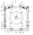
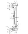
以下、本発明の一実施の形態に係るテープ接着装置10について、図1から図11に基づいて説明する。図1は、図2に示す蓋体部60を透視した状態の本体部20の平面図で、ゴムシート25上にウエハ11を載置した状態を示す図である。また、図2は、テープ接着装置10において、蓋体部60を閉じた状態を示す平面図である。また、図3はテープ接着装置10の一部の内部構成(ゴムシート25等)を透過した状態の側面図である。また、図4は、図1のテープ接着装置10の排気系統及び制御系統の様子を簡略化して示す概略構成図である。 Hereinafter, a
図1に示すように、本体部20の平面形状は、例えば略正方形といった方形を為している。本体部20の底面には、複数(例えば4本)の支持脚21(図3参照)が取り付けられている。また、図3に示すように、テープ接着装置10は、本体部20と、この本体部20に対して回動自在に設けられている蓋体部60とを有している。 As shown in FIG. 1, the planar shape of the
図3および図4に示すように、本体部20の内部には、蓋体部60に対して近接対向する本体上面部22が設けられている。本体上面部22は、真空吸引時に負荷される圧力(特に蓋体部60側から負荷される垂直荷重)を受け止めるために、適切な強度を有した構成となっている。また、本体部20を支えると共にその一部となる側壁および底壁も、真空吸引時に負荷される圧力に、十分抗し得るだけの強度を有する構成である。 As shown in FIGS. 3 and 4, a main body
また、図1、図3および図4に示すように、本体上面部22のうち、外周側には、シールリング23が取り付けられている。シールリング23は、Oリング状の部材であり、後述する蓋体部60のリング当接部63に当接する。それによって、テープ接着装置10の内部を、外部(大気)から密閉し、該テープ接着装置10の内部を真空吸引することを可能としている。 As shown in FIGS. 1, 3, and 4, a
また、本体上面部22のうち、シールリング23よりも中央部側(図1および図4参照;以下、内径部22aという)には、載置部22bが設けられている(図4参照)。載置部22bは、後述するゴムシート25を載置するための部分である。なお、載置部22bは、その上方側(蓋体部60側)が吸引排気された場合でも、上方側に撓むのを防ぐため、十分な肉厚を有している。 Further, in the
載置部22bの略中央部分には、孔部24(図4および図6参照)が設けられている。この孔部24は、後述する空気管路38が嵌め込まれている。そして、この空気管路33を介して、後述する空気導入部51に存在する空気を吸引し、または空気導入部51に空気を供給することを可能としている。このため、孔部24は、ゴムシート25で覆われる状態となる。 A hole 24 (see FIGS. 4 and 6) is provided in a substantially central portion of the mounting
なお、空気導入部51は、図4、図6等においては、孔部24のうち、ゴムシート25と開口部39とで囲まれた部分となっている。しかしながら、ゴムシート25が上底面64a側に向かって膨張すると、空気導入部51の領域も拡大され、孔部24と開口部39等で囲まれる部分のみならず、載置部22bの上面とゴムシート25とで囲まれる部分も、空気導入部51となる。 In FIG. 4, FIG. 6, and the like, the
また、以下の説明においては、シールリング23、リング当接部63、内径部22aおよびゴムシート25によって囲まれる空間を、真空室50とする。 In the following description, a space surrounded by the
また、載置部22bには、孔部24を覆うように、伸縮シート部材としてのゴムシート25が設けられている。このゴムシート25は、その上面に、ワークとしてのウエハ11が搭載される部材である。後述するように、ゴムシート25にウエハ11が搭載された状態で、ゴムシート25を上側に膨らませると、ウエハ11が後述するテープ部材12に向かって上昇する。 Moreover, the mounting
ゴムシート25は、例えばクロロプレンといった、気泡の発生を低減できる材質によって構成されている。しかしながら、ゴムシート25の材質は、かかるクロロプレンに限られるものではなく、通常の天然ゴム又は合成ゴム等を用いても良い。なお、ゴムシート25の好ましい材質としては、上述のクロロプレンのような、気泡の発生を防ぐことができる材質である。 The
また、本実施の形態では、ゴムシート25の上面に搭載されるウエハ11は、その直径が12インチとなっている。しかしながら、ウエハ11のサイズは特に限定されず、例えば8インチウエハ等、他のサイズであっても良い。なお、ウエハ11のサイズを変更する場合には、それに応じて他の部材(ゴムシート25、押さえリング26等)のサイズも変更されることになる。しかしながら、例えば8インチウエハ等の小さいサイズのウエハ11への接着に際して、12インチのウエハ11の接着に対応しているテープ接着装置10を利用しても良い。 In the present embodiment, the diameter of the
図1および図5に示すように、ゴムシート25の上部であって外周縁部には、外観が略リング状となっている、保持部材としての押さえリング26が取り付けられている。押さえリング26は、ゴムシート25を押さえつけるためのものである。この押さえリング26は、内径部22aに対して、例えばネジ26a(図1参照)によって、その上方側から押さえつけるものであって、周方向に沿って適宜の間隔で固定されている。なお、このネジ26aによる固定に際しては、該ネジ26aがゴムシート25を貫通する状態となる。そのため、ゴムシート25に対して、予めネジ26aの貫通孔に対応する孔を形成するようにしても良い。 As shown in FIGS. 1 and 5, a
また、図4に示すように、真空室50を真空吸引するために、該真空室50の内部には、空気管路33の端部側が配置されている。この空気管路33の一端部33aは、4本に分岐している(図4は、断面図のため、2本のみ表示)。そして、分岐している夫々の空気管路33の開口部34が、図4に示すように、真空室50の内部に存在している。なお、開口部34は、本実施の形態では、図1に示す平面図において、略90度間隔となるように配置されている。また、開口部34は、シールリング23の内部側である内径部22aであって押さえリング26とシールリング23の間に存在している。しかしながら、開口部34の位置は、この部位には限られず、例えば押さえリング26の上方に差し掛かる部位に設けても良い。 Further, as shown in FIG. 4, in order to vacuum-suck the
また、空気管路33は、内径部22aを貫通していて、本体部20の下方において、または本体部20の外部において、分岐状態から1つに合流している(図4参照)。また、空気管路33の他端部33bは、本体上面部22の底壁22cから下方に向かって突出している。そして、この他端部33bに対して、管部材35の一端部を接続し、該管部材35の他端部35bを真空ポンプ36に接続する。それによって、真空ポンプ36が作動すると、真空室50を真空吸引することが可能となっている。 Further, the
また、管部材35の中途部分には、第1の弁部材37が設けられている。この第1の弁部材37は、真空室50の内部を真空吸引するために、真空ポンプ36側と連通するように切り替える(以下、この切り替えを、吸引側への切り替えという。)ことを可能としていると共に、大気導入側へ開放するように切り替える(図3において突出管部35a側への切り替え;以下、この切り替えを、大気導入側への切り替えという。)ことも可能となっている。第1の弁部材37の切り替えにより、管部材35が大気導入側へ開放されると、該管部材35を介して、真空室50の内部に、大気が導入される。また、第1の弁部材37としては、例えば、ソレノイドにより開閉可能な、電磁弁を用いることが可能であるが、モータ等の他の駆動源を用いて開閉する方式であっても良い。 A
また、真空ポンプ36は、本実施の形態では、本体部20の外部に設けられている。しかしながら、本体部20の内部に、真空ポンプ36を内蔵する構成を採用しても良い。なお、この真空ポンプ36、空気管路33、管部材35、第1の弁部材37等によって、第1の吸引手段が構成される。また、第1の弁部材37、空気管路33、管部材35、突出管部35a等によって、第2の空気導入手段が構成される。 Further, the
また、これらの真空ポンプ36、および第1の弁部材37は、後述する制御装置90に接続されていて、該制御装置90からの制御指令に対応した信号を受信した後に作動する。 The
また、図4および図6に示すように、ゴムシート25の裏面側に向かうように、上述の空気管路33と同様の、空気管路38が設けられている。この空気管路38は、空気管路33とは異なり、上述の孔部24に挿通するように、1本のみ設けられている。また、空気管路38の開口部39は、該孔部24の内部に存在している(図6参照)。なお、本実施の形態では、孔部24が内径部22aの中心に位置しているため、開口部39も、内径部22aの中心に位置する構成となる。 As shown in FIGS. 4 and 6, an
また、上述の空気管路33と同様に、空気管路38の他端部38bは、本体上面部22の底壁22cから下方に向かって突出していると共に、この他端部38bに対して、管部材40の一端側が接続されている。また、管部材40の他端部は、真空ポンプ36に接続されている。それにより、真空ポンプ36が作動すると、空気導入部51を真空吸引することを可能としている。 Similarly to the
また、管部材40の中途部分にも、第2の弁部材41が設けられている。この第2の弁部材41も、上述の第1の弁部材37と同様に、真空ポンプ36側と連通するように切り替える(吸引側へ切り替える)ことを可能としていると共に、突出管部40aを介して大気導入側へ開放するように切り替えることが可能である。第2の弁部材41の切り替えにより、管部材40が大気導入側へ開放されると、該管部材40を介して、空気導入部51に、大気が導入される。また、第2の弁部材41も、制御装置90に電気的に接続されている。 A
なお、真空ポンプ36、第2の弁部材41、空気管路38、管部材40によって、第2の吸引手段が構成される。また、第2の弁部材41、空気管路38、管部材40、突出管部40a等によって、空気導入手段が構成される。 The
さらに、図4に示すように、本体部20の内部には、上述の管部材35,40と同様な管部材42が設けられている。この管部材42は、例えば本体部20の後端側(蝶番61側)に向かっていて、その一端側42aが本体部20の背面から突出している。なお、管部材42の一端側42aに、管継手を取り付けるようにしても良い。管部材42の一端側42aには、柔軟に曲がることが可能なホース43の一端側43aが連結されている。ホース43は、本体部20から上方の蓋体部60側に向かって延伸していると共に、蝶番61側から手前側(図1および図2に示す取手73a側)に向かい蓋体部60の上面側に沿って設けられている。そして、ホース43の他端側43bは、蓋体部60の上面の径方向の略中心部分において、後述する空気管路67の一端側と連結されている。 Furthermore, as shown in FIG. 4, a
このように、管部材42と空気管路67の間に、柔軟に曲がるホース43が設けられているため、蓋体部60の開閉(回動)に対応可能となっている。 As described above, since the
また、管部材42の中途部分には、上述した第1の弁部材37および第2の弁部材41と同様の、第3の弁部材44が設けられている。第3の弁部材44も、真空ポンプ36側と連通するように切り替える(吸引側へ切り替える)ことを可能としていると共に、突出管部42bを介して大気導入側へ開放するように切り替えることが可能である。なお、管部材42が大気導入側へ開放されると、この管部材42を介してテープ部材12の裏面側(図4においてテープ部材12の上面側)に大気が導入される。それにより、テープ部材12の保持状態が解除される。また、第3の弁部材44も、制御装置90に電気的に接続されている。 In addition, a
なお、真空ポンプ36、管部材42、ホース43、第3の弁部材44、空気管路67によって、第3の吸引手段が構成される。また、後述する吸着部材66、真空ポンプ36、管部材42、ホース43、第3の弁部材44、空気管路67、挟持部材70によって、テープ保持手段が構成される。 The
ここで、本実施の形態では、上述のように、柔軟なホース43を用いることにより、真空ポンプ36で生じる吸引力を蓋体部60側に伝達すると共に、蓋体部60の開閉(回動)に対応させている。しかしながら、真空ポンプ36で生じる吸引力を蓋体部60側に伝達するための構成は、ホース43を用いるものには限られない。例えば、真空吸引するためのホース43等の部材が、テープ接着装置10から外部に突出していていない構成が望まれる場合もある。 Here, in the present embodiment, as described above, by using the
このような場合には、例えば、蓋体部60のリング当接部63に蓋側開口を形成すると共に、本体上面部22のうち蓋側開口と対向する部位に本体側開口を形成する。これらと共に、蓋側開口または本体側開口の少なくとも一方の周囲に、リング状のゴムシールを突出するように取り付ける。また、蓋側開口には、管部材の一端側を連結し、該管部材の他端側を凹部64に連通させる。また、本体側開口には、上述したのと同様の空気管路を設ける。このようにすれば、蓋体部60を閉じたときに、管部材と空気管路とが接続される。また、ゴムシールがリング当接部63と本体上面部22の間に介在して、蓋側開口と本体側開口の両者を気密に塞ぐ状態となる。 In such a case, for example, a lid side opening is formed in the
また、本体部20と蓋体部60とが対向する部位のうち、蝶番61が存在する部位に、折れ曲がり自在かつ伸縮自在な、蛇腹状の管継手を設け、この管継手を介して、本体部20の内部に設けられる管部材と、蓋体部60の内部を進行する空気管路とを連結するようにしても良い。 Further, among the portions where the
また、本実施の形態では、真空ポンプ36は1つのみ設けられている。また、第1〜第3の弁部材37,41,44を大気導入側および吸引側に切り替えることによって、真空室50、空気導入部51、およびテープ部材12の裏面側(上面側)の少なくとも1つの真空吸引や大気圧化を可能としている。 In the present embodiment, only one
しかしながら、真空ポンプ36は、1つには限られるものではなく、第1の吸引手段、第2の吸引手段および第3の吸引手段の夫々に対応させて、真空ポンプ36を2つまたは3つ以上設けるように構成でしても良い。また、第1の弁部材37、第2の弁部材41および第3の弁部材44といった三方弁を用いずに、吸引側の弁部材及び大気導入側の弁部材の両方を、夫々の管部材35、管部材40および管部材42に設けるようにしても良い。このようにしても、真空室50、空気導入部51およびテープ部材12の裏面側(上面側)の吸引/非吸引を良好に切り替えることができる。 However, the number of
さらに、図3に示すように、本体部20の側壁の外面には、真空計45が取り付けられている。この真空計45は、本実施の形態では、2つ設けられている。しかしながら、本実施の形態では、管部材35,40,42の個数に対応させて、3つ設けるのが好ましい。かかる真空計45のうちの1つは、真空室50の内部の気圧を測定するためのものである(以下、必要に応じて真空計45aという)。また、真空計45のうちの他の1つは、空気導入部51の気圧を測定するためのものである(以下、必要に応じて真空計45bという。)。なお、かかる2つの真空計45a,45bも、制御装置90に接続されている。 Further, as shown in FIG. 3, a
また、本体上面部22のうち、例えば後述する蝶番61から最も離間している2つのコーナ部分のうち、一方のコーナ部分22d(図1参照)には、センサ46が設けられている。センサ46は、例えば磁気センサを用いていて、本体部20に対して蓋体部60が、所定だけ近接するまで閉じたか否かを検出するものである。なお、このセンサ46も、制御装置90に接続されていて、この制御装置90に対して蓋体部60が閉じているか否かの検出信号を送信する。そして、制御装置90は、蓋体部60が閉じている状態に対応した検出信号を受信したときのみ、真空ポンプ36等に対して作動に対応した信号を送信する。 In addition, a
次に蓋体部60の構成について説明する。図1、図2および図5に示すように、蓋体部60は、本体部20に対して蝶番61を介して接続されている。すなわち、蝶番61を支点として、蓋体部60は回動可能となっている。また、図1に示すように、蓋体部60には、2つのダンパ部材62の各一端側62aが取り付けられている。また、ダンパ部材62の各他端側62bは、本体上面部22に取り付けられている。このダンパ部材62は、伸縮自在となっていると共に、内部に存在する粘性体(油等)の粘性抵抗によって、急激に蓋体部60が本体部20に対して降下するのを防止している。 Next, the configuration of the
なお、ダンパ部材62は、バネ部材(不図示)も内蔵していて、蓋体部60が開いた状態(例えば、図7(a)に示す状態)を維持可能となっている。しかしながら、蓋体部60が開いた状態を維持する必要がない場合には、バネ部材を省略する構成としても良い。 The
また、図3及び図4に示すように、蓋体部60のうち、本体部20のシールリング23に当接する部分は、リング当接部63となっている。リング当接部63は、シールリング23との当接によって、真空室50を密閉する。なお、かかる密閉を良好にするために、リング当接部63は、本実施の形態では同一平面をなす、平板状の部分から構成されている。 Further, as shown in FIGS. 3 and 4, a portion of the
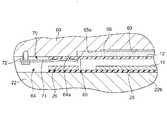
図3〜図5に示すように、蓋体部60のうち、本体部20と対向する対向面であって、リング当接部63よりも内径側の部位には、凹部64が形成されている。この凹部64は、リング当接部63よりも窪んだ状態に形成されている。この凹部64は、上述の内径部22aに対応する大きさを有している。このため、蓋体部60を閉じて、シールリング23がリング当接部63に当接する密閉状態となると、この凹部64、シールリング23、内径部22a、およびゴムシート25で囲まれた空間が出現する。そして、この空間が、真空室50となる。 As shown in FIGS. 3 to 5, a
また、凹部64のうち、上方に位置する底面(以下、上底面64aという。)は、ゴムシート25が膨張する際に、テープ部材12の周縁部が上方へ移動するのを押さえる(受け止める)部分となる。このため、凹部64は、テープ部材12の周縁部を受け止めて、該テープ部材12のウエハ11に対する接着を良好に行える深さに設定されている。 In addition, a bottom surface (hereinafter referred to as an
凹部64には、嵌合凹部65が設けられている。嵌合凹部65は、凹部64から上面側に向かって窪んでいる部位であり、また凹部64よりも小径に設けられている。この嵌合凹部65には、例えば多孔質セラミックスのような、多孔質の材質からなる吸着部材66が嵌め込まれる。かかる吸着部材66を介して、テープ部材12は、吸引保持される。なお、吸着部材66は、嵌合凹部65への嵌め込みに対応して、該嵌合凹部65より僅かに小さな寸法を有している。 The
また、図4および図6に示すように、蓋体部60には、空気管路67が設けられている。空気管路67は、その断面形状が略L字を為すように設けられている。それにより、空気管路67の一端側は、蓋体部60の上面に沿う状態で設けられると共に、空気管路67の他端側は、蓋体部60を貫いて、嵌合凹部65に到達する状態で設けられている。なお、空気管路67の他端側のうち、嵌合凹部65に対して開口している部分を、開口部68とする。また、本実施の形態では、蓋体部60の上面には、固定部材67aが設けられていて、空気管路67は、この固定部材67aを介して、蓋体部60の上面に取り付けられている。 As shown in FIGS. 4 and 6, the
ここで、嵌合凹部65には、該嵌合凹部65の上底面65aよりも僅かに窪んだ窪み部69が設けられるようにするのが好ましい。この場合、窪み部69は、嵌合凹部65の直径よりも小さい直径を有する形状とし、吸着部材66の外周部分を窪み部69以外の嵌合凹部65の上底面65aで受け止めるようにする。かかる窪み部69が存在する場合、窪み部69と吸着部材66の間で生じている負圧が、大面積化される。そのため、吸着部材66は、ウエハ11に対して大面積の状態で吸着可能となる。 Here, the
また、図3、図5および図8に示すように、嵌合凹部65の外側であって、凹部64の内部には、テープ部材12の隅部を固定するための挟持部材70が設けられている。図5に示すように、挟持部材70は、板バネ71を具備し、この板バネ71の一端側がネジ72によって凹部64に取り付けられている。また、板バネ71の他端側は、付勢力によって上底面64aに押し付けられているが、板バネ71の他端側は、板バネ71の付勢力に抗しながら開放可能となっている。なお、本実施の形態では、挟持部材70は、凹部64の周方向において、略90度間隔で4つ設けられている。 As shown in FIGS. 3, 5, and 8, a clamping
また、蓋体部60の側壁部分であって蝶番61と対向する部分には、取手73aが取り付けられている。そのため、作業者は取手73aを把持して蓋体部60を容易に開閉することができる。なお、本体部20の側壁部分には、相対向するように2つずつ、計4つの取手73bが設けられている。この取手73bを持つことで、テープ接着装置10を容易に移動させることができる。 A
また、図2、図8および図9に示すように、テープ接着装置10には、開閉ロック手段としてのロック機構80が設けられている。ロック機構80は、本体部20側に取り付けられているブロック部81を具備している。このブロック部81には、ネジ孔82が設けられていて、該ネジ孔82には、レバー部材83のネジ部84が捻じ込まれる。また、レバー部材83は、ネジ部84と、このネジ部84の軸線からずれる方向に向かって突出する把持部85と、を具備している。 As shown in FIGS. 2, 8, and 9, the
このうち、ネジ部84には、ネジ孔82と螺合するためのネジ山が形成されている。このネジ部84には、クランプ部材86が挿通される。また、把持部85は、作業者が把持する部分であり、かかる把持によりレバー部材83を回転させることが可能となる。 Among these, the
ネジ部84に挿通されるクランプ部材86は、直方体部材であり、ネジ部84に対して回動自在に設けられている。このクランプ部材86の長手は、蓋体部60の側縁方向に対して垂直を為す配置にすることができ、その場合には、蓋体部60の上部にクランプ部材86が差し掛かって、蓋体部60の開放が阻止される。また、クランプ部材86の長手が蓋体部60の側縁方向に対して平行を為す配置にすることもでき、その場合には、蓋体部60の上部にクランプ部材86が差し掛からなく、蓋体部60の開放を許容する状態となる。 The
なお、本実施の形態では、蓋体部60のうち、クランプ部材86と対向する部位には、ボルト87が取り付けられていて、かかるボルト87に対してクランプ部材86が当接する構成となっている。 In the present embodiment, a
また、図4に示すように、テープ接着装置10には、制御手段としての制御装置90が設けられている。制御装置90は、上述したように、真空ポンプ36、第1〜第3の弁部材37,41,44、真空計45、センサ46に対して電気的に接続されている。この制御装置90には、オン作動を行うための操作ボタン(不図示)が連結されている。このため、センサ46がオン作動を許可する蓋体部60の閉塞状態において、作業者が操作ボタンを押すと、真空ポンプ36が作動する。 Further, as shown in FIG. 4, the
ここで、制御装置90は、初めに第2の弁部材41および第3の弁部材44を吸引側に切り替えると共に、第1の弁部材37を大気導入側に切り替えた状態を維持して、所定時間だけゴムシート25およびウエハ11の真空吸引を行うように、第1〜第3の弁部材37,41,44の夫々に対して制御信号を発する。そして、所定時間経過後に、第1の弁部材37に対して制御信号を発し、第1の弁部材37を大気導入側から吸引側に切り替えて、真空室50に対しても、真空吸引を行う。 Here, the control device 90 first switches the
また、制御装置90は、真空室50および空気導入部51が、所定の真空度に到達したことがセンサ46によって計測された場合に、第2の弁部材41に対して、大気導入側に切り替えるための制御指令を発する。それによって、ゴムシート25が膨張し、ウエハ11とテープ部材12との間の接着が開始される。さらに、この状態から所定時間経過して接着が終了した後に、制御装置90は、第1の弁部材37に対して大気導入側に切り替えるための制御指令を発する。かかる切り替えにより、真空室50および空気導入部51の両方とも、大気圧と等しい状態となり、接着動作が終了する。 Further, the control device 90 switches the
さらに、制御装置90は、真空ポンプ36を逆回転させると共に第1の弁部材37または第3の弁部材44を吸引側と同じ側に切り替える。それにより、真空室50の内部に空気が加圧状態で導入される。なお、真空ポンプ36を逆回転させる構成を採用せずに、真空ポンプ36の吐出側に接続されている管部材、および真空ポンプ36の流入側に別途接続されている大気を導入可能な管部材との間の接続を切り替える等により、真空室50の内部の加圧状態を実現するように構成しても良い。 Further, the control device 90 reversely rotates the
なお、上述の所定の真空度としては、約20Pa程度とする場合が、その一例として挙げられる。しかしながら、所定の真空度はこれに限られるものではなく、大気圧よりも低い状態であれば、どのような真空度であっても良い。また、制御装置90は、接着が終了した後には、第1の弁部材37を大気導入側に切り替える作動と共に、真空ポンプ36を停止させるように、真空ポンプ36に対して制御指令を発するように構成しても良い。しかしながら、この場合には、真空ポンプ36を動作継続させる場合と比較して、次の真空吸引の際の吸引時間が、多少長くなる。 An example of the above-mentioned predetermined degree of vacuum is about 20 Pa. However, the predetermined degree of vacuum is not limited to this, and may be any degree of vacuum as long as it is lower than atmospheric pressure. In addition, the controller 90 issues a control command to the
以上のような構成を有するテープ接着装置10の作用(動作)について、以下に説明する。なお、この作用(動作)については、図10に示す動作フローに基づいて、実行される。 The operation (operation) of the
最初に作業者は、蓋体部60を開放させ、ゴムシート25にウエハ11を載置すると共に、テープ部材12を挟持部材70に取り付ける(ステップS10)。この場合、テープ部材12が板バネ71と上底面64aとによって挟持される状態とする。それにより、テープ部材12の裏面は、吸着部材66に当接する状態となると共に、テープ部材12の粘着面(表面)が、下方を向く状態となる。 First, the operator opens the
なお、挟持部材70によりテープ部材12を取り付けた場合、真空ポンプ36を作動させるようにしても良い。真空ポンプ36を蓋体部60の開放状態において作動させた場合には、管部材42、空気管路67を介して吸引保持力が吸着部材66に伝達される。それにより、テープ部材12が吸着部材によって吸引保持される状態となる。そして、このテープ部材12の吸引保持によって、蓋体部60の開放状態において、テープ部材12にしわが存在しない状態となる。 When the
次に、センサ46によって蓋体部60が閉じたことが検出されるまで、蓋体部60を本体部20に対して降下させる(ステップS11)。そして、センサ46がこの降下による蓋体部60の閉塞状態を検出したか否かを、制御装置90は判断する(ステップS12)。そして、センサ46が閉塞状態を検出した場合には、制御装置90は真空ポンプ36の作動を許可する。この状態において、作業者が操作ボタンを押したときに、真空ポンプ36が作動を開始する。 Next, the
また、蓋体部60が閉じ状態となった後に、作業者は、クランプ部材86を回転させて、該クランプ部材86の先端部分が蓋体部60の上面に差し掛かる状態とする。この後に、作業者がレバー部材83を把持し、該レバー部材83を閉じ方向に回転させ、クランプ部材86の下面をボルト87に当接させる。この当接状態において、さらにレバー部材83を閉じ方向に回転させると、蓋体部60は、クランプ部材86によって押され、リング当接部63がシールリング23に押し付けられる。なお、レバー部材83を回転させる場合、全てのレバー部材83を順次少しずつ回転させていき、ロック状態に偏りが生じないようにするのが好ましい。 In addition, after the
そして、所定だけレバー部材83を閉じ回転させると、リング当接部63によりシールリング23が押圧されて弾性変形し、真空室50の内部が外部から気密に閉塞される状態となる(ステップS13)。このように、ロック機構80により蓋体部60の開放をロックすると、真空室50の内部が加圧されても、蓋体部60が持ち上がって開放することがなく、真空室50を外部から封止することができる。 When the
次に、作業者が操作ボタンを押すと、制御装置90がその押し込みを検知して、真空ポンプ36に対して作動のための指令を発する。それにより、真空ポンプ36が作動して、真空室50、テープ部材12およびゴムシート25の真空吸引を行う(吸引ステップに対応)。なお、蓋体部60の開放状態において、テープ部材12の吸引保持が為されている場合には、この吸引保持が継続される状態となる。また、上述の真空ポンプ36の作動に際しては、初めは第2の弁部材41および第3の弁部材44を吸引側に切り替えると共に、第1の弁部材37を大気導入側に切り替えて、テープ部材12およびゴムシート25の真空吸引を先に行う(ステップS14)。 Next, when the operator presses the operation button, the control device 90 detects the pressing and issues a command for operation to the
そして、かかるテープ部材12およびゴムシート25の真空吸引を所定時間行った後に、第1の弁部材37を大気導入側から吸引側に切り替えて、テープ部材12およびゴムシート25と共に、真空室50の真空吸引行う(ステップS15)。 Then, after vacuum suction of the
所定時間、真空ポンプ36が真空吸引を行うと、真空室50およびゴムシート25の裏面側が、所定の真空度に達したことが、真空計45によって検出される(ステップS16;真空度到達検出ステップに対応)。かかる真空計45が所定の真空度を検出すると、所定の検出信号を制御装置90に対して送信する。すると、制御装置90は、真空ポンプ36の作動を維持したままで、第2の弁部材41を大気導入側に切り替える(ステップS17;空気導入ステップに対応)。それによって、空気導入部51には、突出管部40aを介して大気が導入される。 When the
空気導入部51に大気が導入されると、真空室50と空気導入部51に存在する圧力差によって、ゴムシート25が真空室50側に向かって膨張する。この場合、ゴムシート25の膨張によってウエハ11が持ち上げられ、該ウエハ11の上面がテープ部材12に接触する。そして、ウエハ11の上面に対して、テープ部材12の接着が開始される(ステップS18;接着ステップに対応)。 When the atmosphere is introduced into the
ここで、ウエハ11の上面とテープ部材12との間における、接着の態様には、図11(a),(b)に示すような、2通りがある。まず、その1通り目としては、図11(a)に示すような、ウエハ11がテープ部材12に対して傾斜せずに平行な状態を維持して、該ウエハ11の上面の略中央部分から、テープ部材12に接着する場合である。 Here, there are two types of bonding between the upper surface of the
この場合には、ウエハ11がゴムシート25の膨張により持ち上げられると、吸着部材66での保持により弛みが解消されているテープ部材12に対して、ウエハ11の中央部分から接触する。この接触状態から、さらにゴムシート25が膨張する場合、ゴムシート25の中央部分は、ウエハ11の中央部がテープ部材12に触れるため、これ以上移動できないが、引き続きゴムシート25の周辺側が、膨張により上方へ移動して、ウエハ11をテープ部材12に順次接触させてゆく。 In this case, when the
このため、ウエハ11は、ゴムシート25が膨張するにつれて、周辺部の撓みがなくなり、テープ部材12に対し、中心側から周辺側に向かって順次接着が進行する。なお、この状態のまま、所定時間経過すると、ウエハ11とテープ部材12との間の接着が、確実に実行された状態となる。 For this reason, as the
以上のような接着態様では、ウエハ11(テープ部材12)の中央部分から外方に向かって、空気を逃がしながら、ウエハ11の上面とテープ部材12との間の接着が実行される。なお、この接着態様においては、真空ポンプ36は、真空室50側を真空吸引している状態を継続している。このため、上述の接着態様と相俟って、ウエハ11の上面とテープ部材12との間に存在する空気が排除されることによって、ウエハ11とテープ部材12との接着が、良好な状態で為される。 In the bonding mode as described above, bonding between the upper surface of the
また、接着の態様の2通り目としては、図11(b)に示すような、ウエハ11がテープ部材12に対して傾斜した状態で、該傾斜しているウエハ11のうちの最も高い部分(以下、上端とする。)から、テープ部材12に接着する場合である。この場合には、まず傾斜しているウエハ11のうち、上端からテープ部材12に対する接着が開始される。つまり、ウエハ11がゴムシート25の膨張に伴なって持ち上げられると、吸着部材66での保持により弛みが解消されているテープ部材12に対して、ウエハ11のうち上端から接着が開始される。 Further, as a second mode of bonding, as shown in FIG. 11B, the highest portion of the inclined wafer 11 (with the
ここで、テープ部材12は吸着部材66によって保持されているため、テープ部材12がウエハ11により押されても、テープ部材12は上方に移動しない。そのため、ゴムシート25が徐々に膨張すると、ウエハ11のうちテープ部材12への接触部分(上端部分)を支点としつつ、ウエハ11の傾斜角度が徐々に狭まる状態で、該ウエハ11が持ち上げられる。そして、このウエハ11の持ち上げは、ウエハ11の傾斜角度がゼロとなるまで実行される。なお、ウエハ11の傾斜角度がゼロとなって所定時間経過すると、ウエハ11とテープ部材12との間の接着が、確実に実行された状態となる。 Here, since the
以上のような接着態様では、ウエハ11(テープ部材12)の上端から、他方側の端部に向かって、空気を逃がしながら、ウエハ11の上面とテープ部材12との間の接着が実行される。なお、この接着態様においても、真空ポンプ36は、真空室50側を真空吸引している状態を継続している。このため、上述の接着態様と相俟って、ウエハ11の上面とテープ部材12との間に存在する空気が排除されることによって、ウエハ11とテープ部材12との接着が、良好な状態で為される。 In the bonding mode as described above, bonding between the upper surface of the
以上のようにして、制御装置90は、第1の弁部材37の吸引側への切り替え状態を継続したまま、第2の弁部材41の大気導入側への切り替えを、所定時間継続させる(ステップS19)。それによって、ウエハ11とテープ部材12との間の接着が実行された状態となる。 As described above, the control device 90 continues the switching of the
なお、ウエハ11に対してテープ部材12が接着される際に、空気管路38と空気管路67を介して同時に真空排気されるため、最終的には真空室50とテープ部材12の裏面側とが、同一の圧力となる。このため、真空吸引が進行すると、テープ部材12は、吸着部材66から容易に離れる状態となる。 Note that, when the
ステップS19において、制御装置90が所定時間経過したと判断した場合には、制御装置90は、真空ポンプ36を逆回転させると共に、第3の弁部材44を真空吸引と同じ側(加圧側)に切り替える。同時に、第1の弁部材37および第2の弁部材41を閉じるようにする。 In step S19, when the control device 90 determines that the predetermined time has elapsed, the control device 90 rotates the
それにより、テープ部材12が吸着部材66から離れると共に、真空室50には、空気管路67を介して空気が加圧状態で導入される。この場合、まず真空室50の真空吸引の解除により、ゴムシート25の膨張が解除され、ゴムシート25が載置部22bに載置される状態となる。次に、真空室50は、大気圧よりも高い加圧状態となり、テープ部材12は、ウエハ11に向かって押し付けられ、加圧される(ステップS20;加圧ステップに対応)。かかる加圧により、テープ部材12とウエハ11との間の密着性が高められる。 As a result, the
なお、本実施の形態では、加圧によりテープ部材12等に付与される圧力は、1cm2当たり4〜5kg程度となっている。また、第3の弁部材44のみならず、第1の弁部材37を真空吸引と同じ側(加圧側)に切り替えるようにしても良い。この場合、空気管路67を介してのみならず、空気管路33を介しても、真空室50に対して加圧状態で空気が導入される。In the present embodiment, the pressure applied to the
また、真空ポンプ36を第1〜第3の弁部材37,41,44の個数分だけ設ける場合、第1の弁部材37と第3の弁部材41が接続される真空ポンプ36のうち少なくとも一方を逆回転させて真空室50の内部を加圧する。また、第2の弁部材41を大気導入側に切り替えると共に真空ポンプ36を停止させるか、または第2の弁部材41を真空吸引側に切り替えると共に真空ポンプ36を正回転させて空気導入部51を真空吸引する。このようにすれば、ウエハ11に対してテープ部材12を良好に密着させることができる。 Further, when the
真空室50における加圧状態が所定時間経過したと、制御装置90が判断した場合、制御装置90は真空ポンプ36の作動を停止させ、第1〜第3の弁部材37,41,44を大気導入側に切り替える(ステップS21)。それによって、テープ部材12の裏面側、真空室50および空気導入部51は、大気圧となり、上述の加圧状態が解除される。 When the control device 90 determines that the pressurization state in the
なお、上述のステップS21において、第1〜第3の弁部材37,41,44を大気導入側に切り替えた場合、真空ポンプ36の作動は継続したままの状態を維持している。それによって、次のウエハ11に対する接着作業に、素早く対応可能となっている。しかしながら、かかる作動を停止させるようにしても良い。 In step S21 described above, when the first to
その後に、作業者はレバー部材83を開き方向に回転させて、蓋体部60を開放させる。そして、作業者は、挟持部材70によるテープ部材12の保持を解いて、テープ部材12が接着された状態のウエハ11を取り出す(ステップS22)。以上のようにして、ウエハ11の上面に対するテープ部材12の接着が終了する。 Thereafter, the operator rotates the
なお、ウエハ11の上面に対するテープ部材12の接着が終了した以後は、例えばダイシングプロセスといった、次工程に進行する。 In addition, after the adhesion of the
このような構成のテープ接着装置10によれば、ゴムシート25の膨張を利用して、ウエハ11の上面にテープ部材12を接着させることができる。このため、簡易な構成でありながら、大気圧と真空状態との間の圧力差によって、確実にウエハ11の上面にテープ部材12を接着させることができる。特に、ゴムシート25を用いていることにより、テープ部材12に対してウエハ11が、いわゆる片当たりの状態で接触したとしても、ゴムシート25の弾性変形によって、容易にウエハ11の姿勢を持ち直すことができる。このため、ウエハ11の上面に対するテープ部材12の接着性を、良好とすることができる。 According to the
また、上述のテープ接着装置10を用いた場合、真空室50の内部を加圧することができる。このため、ウエハ11とテープ部材12との間における密着性を一層高めることができ、ウエハ11とテープ部材12との間の接着を、一層確実にすることができる。このため、テープ部材12がウエハ11から簡単に剥離するのを防ぐことができる。 Moreover, when the above-mentioned
また、ゴムシート25の上面に、ウエハ11を載置している。このため、ゴムシート25の弛みの影響を除去することができる。このように、弛みの影響が除去されるので、ゴムシート25に大きな張力を付与する構成を備えなくて済み、構成の簡略化を図ることができる。また、ゴムシート25に付与する張力が小さくて済むので、テープ接着装置10を製造する作業者の工数を削減することができる。また、ゴムシート25を押さえリング26で押さえつける際に、気密性を向上させることができる。 Further, the
さらに、ゴムシート25の膨張を利用するため、ウエハ11を上方のテープ部材12へ移動させる特別な構成を要さずに済む。このため、簡易な構成で、ウエハ11をテープ部材12に向けて(上方へ向けて)移動させることができる。 Further, since the expansion of the
また、テープ部材12は、吸着部材66によって吸着保持される。そのため、例えばテープフレームといった、テープ部材12を張設するための部材、および張設するための部材を支持するための手段を別途設ける必要がなくなり、凹部64の内部に存在する構成を簡略化することができる。また、テープ部材12は吸着部材66によって吸着保持されるため、テープ部材12に対して張力を加える必要がなく、張力負荷によってテープ部材12が伸びてしまうのを防止することができる。また、テープ部材12を保持する際に、該テープ部材12が張設されないため、テープ部材12に対して張力を加えずに済む。このため、ウエハ11に接着されたテープ部材12に、張力に対応した収縮が生じるのを防ぐことができ、テープ部材12の接着状態を良好にすることが可能となる。 The
また、吸着部材66は、多孔質セラミックスから構成されている。このため、テープ部材12の全面に亘って確実に、かつ均一に吸着保持することができる。それによって、テープ部材12に弛みが生じるのを防ぐことができる。 The adsorbing
さらに、テープ部材12は、挟持部材70によって挟持される。それにより、真空室50の内部が真空吸引され、テープ部材12の表面と裏面とで圧力差が生じなくなっても、テープ部材12が吸着部材66から落下するのを防ぐことができる。それにより、ウエハ11に対して、テープ部材12を良好に接着させることができる。 Further, the
また、蓋体部60と本体部20の間には、ロック機構80が設けられている。このロック機構80を用いて、蓋体部60の開放をロックすると、真空室50の内部が加圧されても、蓋体部60が持ち上がって開放するのを防ぐことができる。それにより、真空室50を外部から封止することができ、加圧状態を継続することができる。 In addition, a
さらに、制御装置90は、真空ポンプ36、第1〜第3の弁部材37,41,44、真空計45、センサ46に接続されていて、これらの作動を制御することができる。特に、制御装置90は、真空ポンプ36を作動させて、真空室50および空気導入部51の真空吸引を行い、この真空吸引の後に、第2の弁部材41を大気導入側に作動させて、空気導入部51に大気を導入している。それによって、ゴムシート25を真空室50側に向かって膨張させることができ、弛みを除去したゴムシート25の膨張を利用して、ウエハ11の上面に対して、確実にテープ部材12を接着させることが可能となる。 Furthermore, the control device 90 is connected to the
また、制御装置90は、真空室50および空気導入部51の真空吸引を行うに際して、第1の弁部材37を大気導入側に切り替えると共に、第2の弁部材41を真空吸引側に切り替えて、先に空気導入部51の吸引排気を行っている。このため、真空室50に対して空気導入部51の圧力が最初は低下する。そのため、ゴムシート25は、載置部22bに向かって押し付けられ、先に真空室50側に向かって膨張するのが防止される。それによって、第2の弁部材41が大気導入側に切り替え作動される前の段階で、ウエハ11とテープ部材12とが接着されてしまうのを防ぐことができる。 Further, when performing vacuum suction of the
また、制御装置90は、第2の弁部材41を大気導入側に切り替えて所定時間経過した後に、真空ポンプ36を逆回転させると共に、第3の弁部材44を真空吸引と同じ側(加圧側)に切り替えるように制御している。それにより、真空室50には、空気管路67を介して空気が加圧状態で導入され、テープ部材12は、ウエハ11に向かって押し付けられる。それによって、ウエハ11に対するテープ部材12の接着性(密着度)を高めることができ、テープ部材12がウエハ11から簡単に剥離するのを防ぐことができる。 Further, the control device 90 switches the
以上、本発明の一実施の形態について説明したが、本発明はこれ以外にも種々変形可能となっている。以下、それについて述べる。 Although one embodiment of the present invention has been described above, the present invention can be variously modified in addition to this. This will be described below.
上述の実施の形態では、ゴムシート25の上面にウエハ11を載置している。しかしながら、かかるゴムシート25の上面に、例えば樹脂を材質とするシート状部材を載置し、このシート状部材の上部に、ワークを載置するようにしても良い。このようにすれば、ゴムシート25がこすれる等によって生じる、ワークに対する塵埃の付着を防止することができ、後の洗浄処理装置を用いた洗浄工程等を削減することが可能となる。 In the above-described embodiment, the
また、上述の実施の形態では、シールリング23を本体上面部22に取り付けている。しかしながら、シールリング23は、蓋体部60側に取り付けるようにしても良い。このように構成した場合には、本体上面部22にリング当接部が設けられることになる。 In the above-described embodiment, the
さらに、上述の実施の形態では、伸縮シート部材として、ゴムシート25を用いた場合について説明している。しかしながら、伸縮シート部材は、ゴムシート25に限られるものではなく、例えばエラストマー樹脂等の樹脂を材質とする等、ゴム材質以外の材質から構成されていても良い。また、上述の実施の形態では、保持部材として、押さえリング26を用いる場合について説明している。しかしながら、保持部材は押さえリング26に限られるものではなく、例えば内径部22aに塗布する接着剤等の接着性を有する材質を、保持部材として用いても良い。また、保持部材の形状は、リング状に限られるものではなく、外径が多角形をなすリング形状等、種々の形状を採用することが可能である。 Furthermore, in the above-described embodiment, the case where the
また、上述の実施の形態では、テープ保持手段が吸着部材66を有し、この吸着部材66によってテープ部材12を吸着保持する場合について説明している。しかしながら、テープ部材12を保持するための構成は、これには限られない。例えば、リング状のテープフレームを用いて、テープ部材12を張設する構成を採用しても良い。 In the above-described embodiment, the case where the tape holding unit has the
また、本実施の形態では、テープ部材12を吸着保持するために、多孔質セラミックスを材質とする吸着部材66を用いているが、吸着部材は、多孔質体であればどのような材質であっても良い。多孔質体の他の例としては、スポンジ体が挙げられる。 In the present embodiment, the
また、制御手段としては、予め制御条件が設定されているものでも良く、作業者側で任意に制御条件を設定可能な構成でも良い。さらに、シール部材は、本体部20と蓋体部60との間を気密に閉塞できる構成であれば、どのような形状・構成であっても良い。 Moreover, as a control means, the control condition may be set beforehand, and the structure which can set a control condition arbitrarily on the operator side may be sufficient. Furthermore, the sealing member may have any shape and configuration as long as the sealing member can be hermetically closed between the
また、ワークとしては、ウエハ以外に液晶等のガラス基板や特殊ガラス材、有機EL用のガラス基板等を採用しても良い。また、上述の実施の形態では、真空化後に大気(空気)を導入しているが、空気以外のもの、例えばアルゴンガス等を導入して、加圧する状態としても良い。 In addition to the wafer, a glass substrate such as a liquid crystal, a special glass material, a glass substrate for organic EL, or the like may be employed as the workpiece. In the above-described embodiment, the atmosphere (air) is introduced after evacuation, but a state other than air, such as argon gas, may be introduced and pressurized.
また、上述の実施の形態では、開閉ロック手段として、ロック機構80を用いた場合について説明している。しかしながら、開閉ロック手段は、ロック機構80には限られない。例えば、本体部20側に差込穴を設けると共に、蓋体部60側にバネによる付勢力を受けながら回動する爪部を設け、蓋体部60を閉じた場合に爪部が差込穴に嵌まり込むようにし、爪部の差込穴の内部での係止によって、蓋体部60の開放がロックされるように構成しても良い。また、開閉ロック手段を省略する構成を採用しても良い。 In the above-described embodiment, the case where the
また、テープ部材12は、上述の実施の形態のものには限られず、UV硬化型テープ、偏光フィルム、保護シート、透明電極等、ワークの表面に接着可能であれば、種々のものを用いることができる。 The
また、上述の実施の形態において、テープ接着装置10の内部にワークの表面に接着されているテープ部材12を剥離させるための剥離機構を設けるようにしても良い。この場合、例えば蓋体部60または本体部20の内部に、テープ部材12を剥がすための剥離機構としての吸引保持機構、またはテープ部材12の端部を摘んで剥がす等の機構を、テープ接着装置10の内部に設けるようにしても良い。また、吸引保持機構を設ける場合、上述した真空ポンプ36の吸引を利用する構成を採用しても良い。 Moreover, in the above-mentioned embodiment, you may make it provide the peeling mechanism for peeling the
このような剥離機構を具備することにより、真空吸引されるテープ接着装置10の内部において、テープ部材12を剥がすことができる。そのため、テープ剥がしが為されるに際して、ガラス基板の表面に埃が付着するのを防ぐことができる。特に、現状では、クリーンルーム内でテープ部材12を剥離させても、ワークの表面に埃が付着するのを防止することが困難であるが、本実施の形態のテープ接着装置10を利用する場合、真空内部においてテープ部材12の剥離が為されるため、ワークに埃が付くのを、一層確実に防ぐことができる。 By providing such a peeling mechanism, the
また、別途、ウエハ11やガラス基板にテープ部材12を接着した後に、テープ部材12を切断するための機構を、テープ接着装置10の内部に設けるようにしても良い。 Alternatively, a mechanism for cutting the
また、上述の実施の形態におけるテープ接着装置10は、加圧を行える蓋体部60を具備している。しかしながら、テープ接着装置は、かかる蓋体部60と、空気管路67等を具備せずに加圧を行えないタイプの蓋体部とを容易に交換可能としても良い。 Moreover, the
さらに、上述の実施の形態においては、吸着部材66は、多孔質セラミックスから構成されている。この場合において、多孔質セラミックスを別途加熱する機構を設け、該吸着部材66にセラミックスヒータといった、加熱のための機能を持たせるようにしても良い。この場合には、テープ部材12が加熱されるため、テープ部材12のウエハ11に対する接着性(粘着性)が良好となる。このため、テープ部材12をウエハ11に対して一層強固に接着させることが可能となる。 Furthermore, in the above-described embodiment, the adsorbing
本発明のテープ接着装置およびテープ接着方法は、ウエハを用いた半導体集積回路の製造過程や液晶を用いた液晶表示装置の製造過程において利用することができる。すなわち、半導体製造産業等において利用することができる。また、ガラス基板を用いたディスプレイの製造産業等において利用することもできる。 The tape bonding apparatus and the tape bonding method of the present invention can be used in the manufacturing process of a semiconductor integrated circuit using a wafer and the manufacturing process of a liquid crystal display device using a liquid crystal. That is, it can be used in the semiconductor manufacturing industry. It can also be used in the display manufacturing industry using a glass substrate.
10…テープ接着装置
11…ウエハ(ワーク)
12…テープ部材
20…本体部
22…本体上面部
22b…載置部
24…孔部
25…ゴムシート
26…押さえリング(保持部材)
33…空気管路(第1の吸引手段の一部、第2の空気導入手段の一部)
35…管部材(第1の吸引手段の一部、第2の空気導入手段の一部)
36…真空ポンプ(第1の吸引手段の一部、第2の吸引手段の一部、第3の吸引手段の一部)
37…第1の弁部材(第1の吸引手段の一部、第2の空気導入手段の一部)
38…空気管路(第2の吸引手段の一部、空気導入手段の一部)
40…管部材(第2の吸引手段の一部、空気導入手段の一部)
41…第2の弁部材(第2の吸引手段の一部、空気導入手段の一部)
42…管部材(テープ保持手段の一部、第3の吸引手段の一部)
43…ホース(テープ保持手段の一部、第3の吸引手段の一部)
44…第3の弁部材(テープ保持手段の一部、第3の吸引手段の一部)
45(45a,45b)…真空計
50…真空室
51…空気導入部
60…蓋体部
61…蝶番
62…ダンパ部材
63…リング当接部
64…凹部
64a…上底面
65…嵌合凹部
66…吸着部材(テープ保持手段の一部)
67…空気管路(テープ保持手段の一部、第3の吸引手段の一部)
80…ロック機構
90…制御装置(制御手段)10 ...
DESCRIPTION OF
33 ... Air pipe (part of first suction means, part of second air introduction means)
35 ... Tube member (part of first suction means, part of second air introduction means)
36 ... Vacuum pump (part of first suction means, part of second suction means, part of third suction means)
37 ... 1st valve member (a part of 1st suction means, a part of 2nd air introduction means)
38 ... Air pipe (part of second suction means, part of air introduction means)
40 ... Tube member (part of second suction means, part of air introduction means)
41 ... 2nd valve member (a part of 2nd suction means, a part of air introduction means)
42 ... Tube member (part of tape holding means, part of third suction means)
43 ... Hose (part of tape holding means, part of third suction means)
44 ... Third valve member (part of tape holding means, part of third suction means)
45 (45a, 45b) ...
67 ... Air pipe (part of tape holding means, part of third suction means)
80 ... Lock mechanism 90 ... Control device (control means)
Claims (8)
Translated fromJapanese上面に上記ワークが載置される伸縮シート部材と、
上記伸縮シート部材の上面側に位置すると共に、該伸縮シート部材によって仕切られる真空室と、
上記伸縮シート部材の下面側に位置すると共に、該伸縮シート部材によって仕切られる空気導入部と、
上記伸縮シート部材の下面側であって上記空気導入部と干渉しない部位に位置すると共に、上記伸縮シート部材が載置される載置部と、
上記真空室に対して上記空気導入部からの空気の導通を防止する状態で上記伸縮シート部材を保持する保持部材と、
上記伸縮シート部材に載置される上記ワークの上部で上記テープ部材を保持させるテープ保持手段と、
上記真空室の内部を真空吸引する第1の吸引手段と、
上記空気導入部を真空吸引する第2の吸引手段と、
上記空気導入部に空気を導入する空気導入手段と、
上記真空室の内部に空気を加圧状態で導入する加圧手段と、
上記第1の吸引手段、上記第2の吸引手段、上記空気導入手段および上記加圧手段の作動を制御する制御手段と、
を具備し、
上記制御手段は、
先に上記第2の吸引手段を作動させ、後に上記第1の吸引手段を作動させて、上記真空室および上記空気導入部の真空吸引を行い、
上記真空吸引の後に、上記空気導入手段を作動させて上記空気導入部に空気を導入し、
この空気の導入によって、上記伸縮シート部材を上記真空室の内部に向けて膨張させ、
上記伸縮シート部材の膨張によって、上記ワークを上記テープ部材に向かって持ち上げて上記テープ部材に接着させ、
上記テープ部材の接着後に、上記加圧手段を作動させて上記真空室の内部に空気を加圧状態で導入する、
ことを特徴とするテープ接着装置。In a tape bonding apparatus that bonds a tape member to a workpiece,
An elastic sheet member on which the workpiece is placed on the upper surface;
A vacuum chamber located on the upper surface side of the elastic sheet member and partitioned by the elastic sheet member;
An air introduction part located on the lower surface side of the elastic sheet member and partitioned by the elastic sheet member;
Located on the lower surface side of the stretchable sheet member and located at a site that does not interfere with the air introduction portion, and a placement portion on which the stretchable sheet member is placed;
A holding member that holds the stretchable sheet member in a state that prevents conductionof airfrom the air introduction portion to the vacuum chamber;
Tape holding means for holding the tape member at the upper part of the work placed on the stretchable sheet member;
First suction means for vacuum suction of the inside of the vacuum chamber;
A second suction means for vacuum suction of the air introduction part;
Air introduction means for introducing air into the air introduction section;
A pressurizing means for introducing air into the vacuum chamber in a pressurized state;
Control means for controlling the operation of the first suction means, the second suction means, the air introduction means, and the pressurization means;
Comprising
The control means includes
First actuate the second suction means, and later actuate the first suction means to perform vacuum suction of the vacuum chamber and the air introduction part,
After the vacuum suction, the air introduction means is operated to introduce air into the air introduction unit,
By introducing this air, the expandable sheet member is expanded toward the inside of the vacuum chamber,
By the expansion of the elastic sheet member, the work is lifted toward the tape member and adhered to the tape member,
After the tape member is bonded, the pressure means is operated to introduce air into the vacuum chamber in a pressurized state.
A tape bonding apparatus characterized by that.
上記蓋体部を上記本体部に対して閉じた場合に、上記蓋体部と上記本体部との間を気密に閉塞するシール部材を、これら蓋体部と本体部との境界部分に設けると共に、
上記蓋体部の閉塞状態において、この蓋体部と前記伸縮シート部材との間に、前記真空室が形成される、
ことを特徴とする請求項1記載のテープ接着装置。The tape bonding apparatus includes a main body part and a lid part that is provided to be openable and closable with respect to the main body part.
When the lid body portion is closed with respect to the main body portion, a seal member that hermetically closes between the lid body portion and the main body portion is provided at a boundary portion between the lid body portion and the main body portion. ,
In the closed state of the lid portion, the vacuum chamber is formed between the lid portion and the stretchable sheet member.
The tape bonding apparatus according to claim1, wherein
本体部と、The main body,
上記本体部に対して開閉自在に設けられている蓋体部と、A lid portion that can be opened and closed with respect to the main body portion;
上記本体部と上記蓋体部との境界部分に設けられると共に、上記蓋体部を上記本体部に対して閉じた場合に、上記蓋体部と上記本体部との間を気密に閉塞するシール部材と、A seal that is provided at a boundary portion between the main body portion and the lid body portion and hermetically closes between the lid body portion and the main body portion when the lid body portion is closed with respect to the main body portion. Members,
上面に上記ワークが載置される伸縮シート部材と、An elastic sheet member on which the workpiece is placed on the upper surface;
上記伸縮シート部材の上面側に位置すると共に、該伸縮シート部材によって仕切られ、かつ上記蓋体部の閉塞状態において上記蓋体部と上記伸縮シート部材との間に少なくとも形成される真空室と、A vacuum chamber located on the upper surface side of the stretchable sheet member, partitioned by the stretchable sheet member, and formed at least between the lid body portion and the stretchable sheet member in the closed state of the lid body portion;
上記伸縮シート部材の下面側に位置すると共に、該伸縮シート部材によって仕切られる空気導入部と、An air introduction part located on the lower surface side of the elastic sheet member and partitioned by the elastic sheet member;
上記伸縮シート部材の下面側であって上記空気導入部と干渉しない部位に位置すると共に、上記伸縮シート部材が載置される載置部と、Located on the lower surface side of the stretchable sheet member and located at a site that does not interfere with the air introduction portion, and a placement portion on which the stretchable sheet member is placed;
上記真空室に対して上記空気導入部からの空気の導通を防止する状態で上記伸縮シート部材を保持する保持部材と、A holding member that holds the stretchable sheet member in a state that prevents conduction of air from the air introduction portion to the vacuum chamber;
上記伸縮シート部材に載置される上記ワークの上部で上記テープ部材を保持させると共に、上記テープ部材を吸着する吸着部材を備えるテープ保持手段と、A tape holding means comprising an adsorbing member that adsorbs the tape member while holding the tape member on the upper part of the work placed on the elastic sheet member;
上記真空室の内部を真空吸引する第1の吸引手段と、First suction means for vacuum suction of the inside of the vacuum chamber;
上記空気導入部を真空吸引する第2の吸引手段と、A second suction means for vacuum suction of the air introduction part;
上記空気導入部に空気を導入する空気導入手段と、Air introduction means for introducing air into the air introduction section;
上記真空室の内部に空気を加圧状態で導入する加圧手段と、A pressurizing means for introducing air into the vacuum chamber in a pressurized state;
上記吸着部材に対して上記テープ部材を真空吸引する吸引保持力を与える第3の吸引手段と、A third suction means for providing a suction holding force for vacuum suction of the tape member to the suction member;
を具備すると共に、And having
上記蓋体部は、この蓋体部の閉塞状態において上方に向かって窪んでいる凹部を有すると共に、この凹部の上底面には、上記吸着部材が嵌め込まれていて、上記伸縮シート部材の膨張による上記ワークおよび上記テープ部材の上方へ向かう移動を、上記吸着部材によって上方から押さえる、The lid portion has a concave portion that is recessed upward in the closed state of the lid portion, and the adsorbing member is fitted on the upper bottom surface of the concave portion, and the expansion sheet member is expanded. The upward movement of the workpiece and the tape member is suppressed from above by the suction member.
ことを特徴とするテープ接着装置。A tape bonding apparatus characterized by that.
本体部と、
上記本体部に対して開閉自在に設けられている蓋体部と、
上記本体部と上記蓋体部との境界部分に設けられると共に、上記蓋体部を上記本体部に対して閉じた場合に、上記蓋体部と上記本体部との間を気密に閉塞するシール部材と、
上面に上記ワークが載置される伸縮シート部材と、
上記伸縮シート部材の上面側に位置すると共に、該伸縮シート部材によって仕切られ、かつ上記蓋体部の閉塞状態において上記蓋体部と上記伸縮シート部材との間に少なくとも形成される真空室と、
上記伸縮シート部材の下面側に位置すると共に、該伸縮シート部材によって仕切られる空気導入部と、
上記伸縮シート部材の下面側であって上記空気導入部と干渉しない部位に位置すると共に、上記伸縮シート部材が載置される載置部と、
上記真空室に対して上記空気導入部からの空気の導通を防止する状態で上記伸縮シート部材を保持する保持部材と、
上記伸縮シート部材に載置される上記ワークの上部で上記テープ部材を保持させるテープ保持手段と、
上記真空室の内部を真空吸引する第1の吸引手段と、
上記空気導入部を真空吸引する第2の吸引手段と、
上記空気導入部に空気を導入する空気導入手段と、
上記真空室の内部に空気を加圧状態で導入する加圧手段と、
を具備すると共に、
上記蓋体部と上記本体部の間には、上記蓋体部を上記本体部に向けて押圧し、かつ上記蓋体部が開くのを防止する開閉ロック手段が設けられている、
ことを特徴とするテープ接着装置。In a tape bonding apparatus that bonds a tape member to a workpiece,
The main body,
A lid portion that can be opened and closed with respect to the main body portion;
A seal that is provided at a boundary portion between the main body portion and the lid body portion and hermetically closes between the lid body portion and the main body portion when the lid body portion is closed with respect to the main body portion. Members,
An elastic sheet member on which the workpiece is placed on the upper surface;
A vacuum chamber located on the upper surface side of the elastic sheet member, partitioned by the elastic sheet member, and formed at least between the lid body part and the elastic sheet member in a closed state of the lid part;
An air introduction part located on the lower surface side of the elastic sheet member and partitioned by the elastic sheet member;
Located on the lower surface side of the stretchable sheet member and located at a site that does not interfere with the air introduction portion, and a placement portion on which the stretchable sheet member is placed;
A holding member that holds the stretchable sheet member in a state that prevents conduction of air from the air introduction portion to the vacuum chamber;
Tape holding means for holding the tape member at the upper part of the work placed on the stretchable sheet member;
First suction means for vacuum suction of the inside of the vacuum chamber;
A second suction means for vacuum suction of the air introduction part;
Air introduction means for introducing air into the air introduction section;
A pressurizing means for introducing air into the vacuum chamber in a pressurized state;
And having
Between the lid body part and the main body part, an opening / closing lock means for pressing the lid body part toward the main body part and preventing the lid body part from opening is provided.
A tape bonding apparatus characterized by that .
上記ワークの上部側に位置する上記テープ部材を、テープ保持手段に保持させるテープ保持ステップと、
伸縮シート部材の上面に上記ワークが載置され、かつテープ保持手段によって該ワークの上部に上記テープ部材を張設状態で位置させた状態で、上記伸縮シート部材の上面側に位置する真空室を第1の吸引手段で真空吸引させると共に、上記伸縮シート部材により上記真空室から仕切られると共に該伸縮シート部材の下面側に位置する空気導入部を第2の吸引手段で真空吸引させる吸引ステップと、
上記吸引ステップによって、上記真空室および上記空気導入部が設定された真空度に到達したことを検出する真空到達度検出ステップと、
上記真空到達度検出ステップによって設定された真空度に到達したことを検出した後に、上記第2の吸引手段の作動停止により上記空気導入部の真空吸引を停止すると共に、空気導入手段を作動させて該空気導入部に空気を導入する空気導入ステップと、
上記空気導入ステップの後に、上記伸縮シート部材を上記真空室の内部に向けて膨張させ、かかる伸縮シート部材の膨張によって、上記ワークを上記テープ部材に向かって持ち上げて上記テープ部材に接着させる接着ステップと、
上記接着ステップを予め設定された時間だけ実行した後に、加圧手段を作動させて上記真空室の内部に空気を加圧状態で導入する加圧ステップと、
を具備し、
上記吸引ステップでは、上記第1の吸引手段および上記第2の吸引手段を作動させるに際して、先に上記第2の吸引手段を作動させ、後に上記第1の吸引手段を作動させる、
ことを特徴とするテープ接着方法。In a tape bonding method for bonding a tape member to a workpiece,
A tape holding step for holding the tape member positioned on the upper side of the workpiece by a tape holding means;
A vacuum chamber located on the upper surface side of the stretchable sheet member in a state where the work is placed on the upper surface of the stretchable sheet member and the tape member is positioned in a stretched state on the upper part of the work by the tape holding means. A suction step in which vacuum suction is performed by the first suction means, and the air introduction portion that is partitioned from the vacuum chamber by the stretchable sheet member and located on the lower surface side of the stretchable sheet member is vacuum suctioned by the second suction means;
A vacuum reach detection step for detecting that the vacuum chamber and the air introduction part have reached a set vacuum by the suction step;
After detecting that the degree of vacuum set by the vacuum achievement level detection step has been reached, the vacuum suction of the air introduction unit is stopped by stopping the operation of the second suction unit, and the air introduction unit is operated. An air introduction step for introducing air into the air introduction section;
After the air introduction step, the expansion sheet member is expanded toward the inside of the vacuum chamber, and the expansion of the expansion sheet member lifts the workpiece toward the tape member and adheres it to the tape member. When,
After performing the bonding step for a preset time, a pressurizing step of operating the pressurizing means to introduce air into the vacuum chamber in a pressurized state;
Comprising
In the suction step, when the first suction means and the second suction means are operated, the second suction means is operated first, and the first suction means is operated later.
A tape bonding method characterized by the above.
Priority Applications (6)
| Application Number | Priority Date | Filing Date | Title |
|---|---|---|---|
| JP2004154050AJP4559122B2 (en) | 2004-05-25 | 2004-05-25 | Tape bonding apparatus and tape bonding method |
| CNB200580016642XACN100499062C (en) | 2004-05-25 | 2005-04-12 | Adhesive tape bonding device and adhesive tape bonding method |
| US11/569,471US7621307B2 (en) | 2004-05-25 | 2005-04-12 | Tape adhering apparatus and tape adhering method |
| CN2008101839140ACN101431011B (en) | 2004-05-25 | 2005-04-12 | Tape adhering apparatus and tape adhering method |
| PCT/JP2005/007056WO2005117099A1 (en) | 2004-05-25 | 2005-04-12 | Tape adhering apparatus and tape adhering method |
| US12/606,347US8336595B2 (en) | 2004-05-25 | 2009-10-27 | Tape adhering apparatus and tape adhering method |
Applications Claiming Priority (1)
| Application Number | Priority Date | Filing Date | Title |
|---|---|---|---|
| JP2004154050AJP4559122B2 (en) | 2004-05-25 | 2004-05-25 | Tape bonding apparatus and tape bonding method |
Publications (2)
| Publication Number | Publication Date |
|---|---|
| JP2005340311A JP2005340311A (en) | 2005-12-08 |
| JP4559122B2true JP4559122B2 (en) | 2010-10-06 |
Family
ID=35451147
Family Applications (1)
| Application Number | Title | Priority Date | Filing Date |
|---|---|---|---|
| JP2004154050AExpired - Fee RelatedJP4559122B2 (en) | 2004-05-25 | 2004-05-25 | Tape bonding apparatus and tape bonding method |
Country Status (4)
| Country | Link |
|---|---|
| US (2) | US7621307B2 (en) |
| JP (1) | JP4559122B2 (en) |
| CN (2) | CN100499062C (en) |
| WO (1) | WO2005117099A1 (en) |
Cited By (1)
| Publication number | Priority date | Publication date | Assignee | Title |
|---|---|---|---|---|
| JP2005093987A (en)* | 2003-08-08 | 2005-04-07 | Tsubaki Seiko:Kk | Tape bonding apparatus and tape bonding method |
Families Citing this family (13)
| Publication number | Priority date | Publication date | Assignee | Title |
|---|---|---|---|---|
| CN101809718A (en)* | 2007-12-20 | 2010-08-18 | 立山机械股份有限公司 | Sticking method and sticking device of sticking material |
| JP2013001888A (en)* | 2011-06-21 | 2013-01-07 | Three M Innovative Properties Co | Member joining method and member joining device |
| JP5649125B2 (en)* | 2011-07-01 | 2015-01-07 | Necエンジニアリング株式会社 | Tape applicator |
| JP5893887B2 (en)* | 2011-10-11 | 2016-03-23 | ルネサスエレクトロニクス株式会社 | Manufacturing method of semiconductor device |
| JP5687647B2 (en)* | 2012-03-14 | 2015-03-18 | 株式会社東芝 | Semiconductor device manufacturing method and semiconductor manufacturing apparatus |
| JP6226563B2 (en)* | 2013-05-28 | 2017-11-08 | リンテック株式会社 | Electrostatic holding device and method for removing object to be held from electrostatic holding device |
| JP6271380B2 (en) | 2014-09-12 | 2018-01-31 | アルパッド株式会社 | Semiconductor device manufacturing apparatus and semiconductor device manufacturing method |
| JP6692709B2 (en)* | 2016-06-24 | 2020-05-13 | デクセリアルズ株式会社 | Method for manufacturing joined body, connection method |
| KR102448726B1 (en)* | 2017-08-14 | 2022-09-28 | 삼성전자주식회사 | Laminating apparatus and semiconductor package manufacturing method using same |
| JP7051379B2 (en)* | 2017-11-15 | 2022-04-11 | 芝浦メカトロニクス株式会社 | Film forming equipment and embedding processing equipment |
| MY205366A (en)* | 2018-04-24 | 2024-10-17 | Disco Hi Tec Europe Gmbh | Device and method for attaching protective tape on semiconductor wafer |
| JP7625434B2 (en)* | 2021-02-05 | 2025-02-03 | 株式会社東京精密 | Tape application device |
| TWI852655B (en)* | 2023-06-30 | 2024-08-11 | 友達光電股份有限公司 | Lamination apparatus and lamination method |
Family Cites Families (16)
| Publication number | Priority date | Publication date | Assignee | Title |
|---|---|---|---|---|
| US3972766A (en)* | 1975-01-17 | 1976-08-03 | Andre Fontvieille | Apparatus for fabricating flat objects |
| JPH0254564A (en)* | 1988-08-18 | 1990-02-23 | Nec Corp | Device for application of adhesive tape to semiconductor wafer |
| JP2856216B2 (en)* | 1989-06-09 | 1999-02-10 | 富士通株式会社 | Method of bonding adhesive tape to semiconductor wafer |
| JP2648638B2 (en)* | 1990-11-30 | 1997-09-03 | 三菱マテリアル株式会社 | Wafer bonding method and apparatus |
| JP3156344B2 (en)* | 1992-03-13 | 2001-04-16 | 富士通株式会社 | Method and apparatus for attaching tape to semiconductor wafer |
| JP3570580B2 (en)* | 1995-07-27 | 2004-09-29 | Jfeケミカル株式会社 | Method for producing fiber-reinforced thermoplastic resin molded article |
| JPH1012578A (en)* | 1996-06-26 | 1998-01-16 | Mitsubishi Electric Corp | Wafer / support substrate bonding method and wafer / support substrate bonding apparatus |
| JPH1025456A (en)* | 1996-07-09 | 1998-01-27 | Toyo Chem Co Ltd | Semiconductor wafer fixing sheet |
| JPH10233430A (en) | 1997-02-19 | 1998-09-02 | Nitto Denko Corp | Adhesive tape application device |
| JP3627090B2 (en)* | 1997-09-17 | 2005-03-09 | 株式会社名機製作所 | Lamination molding method and lamination molding apparatus |
| JP2000349047A (en) | 1999-06-01 | 2000-12-15 | Lintec Corp | Device and method for sticking adhesive material |
| DE10048881A1 (en)* | 2000-09-29 | 2002-03-07 | Infineon Technologies Ag | Device for planar joining of two wafers e.g. for thin grinding and separation of product-wafer, has product wafer arranged surface-congruently over carrier wafer |
| JP2003007808A (en)* | 2001-06-20 | 2003-01-10 | Mighty Engineering:Kk | Wafer taping machine using vacuum |
| DE10140133A1 (en)* | 2001-08-16 | 2003-03-13 | Wacker Siltronic Halbleitermat | Method and device for producing an adhesive connection between a semiconductor wafer and a carrier plate |
| JP4143488B2 (en)* | 2003-06-30 | 2008-09-03 | Necエンジニアリング株式会社 | Tape applicator |
| JP4152295B2 (en)* | 2003-10-23 | 2008-09-17 | Necエンジニアリング株式会社 | Tape applicator |
- 2004
- 2004-05-25JPJP2004154050Apatent/JP4559122B2/ennot_activeExpired - Fee Related
- 2005
- 2005-04-12CNCNB200580016642XApatent/CN100499062C/ennot_activeExpired - Fee Related
- 2005-04-12USUS11/569,471patent/US7621307B2/ennot_activeExpired - Fee Related
- 2005-04-12WOPCT/JP2005/007056patent/WO2005117099A1/enactiveApplication Filing
- 2005-04-12CNCN2008101839140Apatent/CN101431011B/ennot_activeExpired - Fee Related
- 2009
- 2009-10-27USUS12/606,347patent/US8336595B2/ennot_activeExpired - Fee Related
Cited By (1)
| Publication number | Priority date | Publication date | Assignee | Title |
|---|---|---|---|---|
| JP2005093987A (en)* | 2003-08-08 | 2005-04-07 | Tsubaki Seiko:Kk | Tape bonding apparatus and tape bonding method |
Also Published As
| Publication number | Publication date |
|---|---|
| WO2005117099A1 (en) | 2005-12-08 |
| US20080210371A1 (en) | 2008-09-04 |
| CN101431011A (en) | 2009-05-13 |
| JP2005340311A (en) | 2005-12-08 |
| CN1957457A (en) | 2007-05-02 |
| US7621307B2 (en) | 2009-11-24 |
| CN101431011B (en) | 2011-04-13 |
| US8336595B2 (en) | 2012-12-25 |
| US20100084096A1 (en) | 2010-04-08 |
| CN100499062C (en) | 2009-06-10 |
Similar Documents
| Publication | Publication Date | Title |
|---|---|---|
| US8336595B2 (en) | Tape adhering apparatus and tape adhering method | |
| JP3326109B2 (en) | Carrier head with substrate detection mechanism for mechanochemical polishing equipment | |
| JP4559183B2 (en) | Tape bonding device | |
| JP5344870B2 (en) | Work bonding machine | |
| JP2002236276A (en) | Substrate assembling method and assembling apparatus | |
| JPH10233430A (en) | Adhesive tape application device | |
| WO2015046243A1 (en) | Suction stage, bonding device, and method for manufacturing bonded substrate | |
| CN100440474C (en) | Adhesive tape bonding device | |
| JP7108467B2 (en) | Substrate suction device | |
| JP2004055833A (en) | Suction device for thin plate | |
| JP2006222231A (en) | Tape bonding device and tape bonding method | |
| JP2011253845A (en) | Tape adhering device and tape adhering method | |
| JP5313973B2 (en) | Tape bonding apparatus and tape bonding method | |
| JP5319539B2 (en) | Tape bonding method and electronic component manufacturing method | |
| JP4738758B2 (en) | Tape bonding apparatus and tape bonding method | |
| JPH05183042A (en) | Suction of wafer | |
| JP6398301B2 (en) | Adsorption / detachment device | |
| JP5317119B2 (en) | Vacuum suction head | |
| JP3832789B2 (en) | Pasting device | |
| JP4457351B2 (en) | Substrate holding device | |
| JP2008066478A (en) | Tape bonding method and electronic component manufacturing method | |
| TWI862149B (en) | Bonding method of substrates | |
| JP7272640B2 (en) | Work mounting device and work bonding system | |
| CN112838022A (en) | Stripping device | |
| KR19990017521U (en) | A Sealing And Height Adjusting Device Using A Suction Disk |
Legal Events
| Date | Code | Title | Description |
|---|---|---|---|
| A621 | Written request for application examination | Free format text:JAPANESE INTERMEDIATE CODE: A621 Effective date:20070524 | |
| A131 | Notification of reasons for refusal | Free format text:JAPANESE INTERMEDIATE CODE: A131 Effective date:20100406 | |
| A521 | Request for written amendment filed | Free format text:JAPANESE INTERMEDIATE CODE: A523 Effective date:20100604 | |
| TRDD | Decision of grant or rejection written | ||
| A01 | Written decision to grant a patent or to grant a registration (utility model) | Free format text:JAPANESE INTERMEDIATE CODE: A01 Effective date:20100622 | |
| A01 | Written decision to grant a patent or to grant a registration (utility model) | Free format text:JAPANESE INTERMEDIATE CODE: A01 | |
| A61 | First payment of annual fees (during grant procedure) | Free format text:JAPANESE INTERMEDIATE CODE: A61 Effective date:20100722 | |
| R150 | Certificate of patent or registration of utility model | Ref document number:4559122 Country of ref document:JP Free format text:JAPANESE INTERMEDIATE CODE: R150 Free format text:JAPANESE INTERMEDIATE CODE: R150 | |
| FPAY | Renewal fee payment (event date is renewal date of database) | Free format text:PAYMENT UNTIL: 20130730 Year of fee payment:3 | |
| R250 | Receipt of annual fees | Free format text:JAPANESE INTERMEDIATE CODE: R250 | |
| R250 | Receipt of annual fees | Free format text:JAPANESE INTERMEDIATE CODE: R250 | |
| R250 | Receipt of annual fees | Free format text:JAPANESE INTERMEDIATE CODE: R250 | |
| R250 | Receipt of annual fees | Free format text:JAPANESE INTERMEDIATE CODE: R250 | |
| R250 | Receipt of annual fees | Free format text:JAPANESE INTERMEDIATE CODE: R250 | |
| R250 | Receipt of annual fees | Free format text:JAPANESE INTERMEDIATE CODE: R250 | |
| R250 | Receipt of annual fees | Free format text:JAPANESE INTERMEDIATE CODE: R250 | |
| R250 | Receipt of annual fees | Free format text:JAPANESE INTERMEDIATE CODE: R250 | |
| LAPS | Cancellation because of no payment of annual fees |