JP4558041B2 - Method for measuring transcutaneous CO2 partial pressure in the earlobe - Google Patents
Method for measuring transcutaneous CO2 partial pressure in the earlobeDownload PDFInfo
- Publication number
- JP4558041B2 JP4558041B2JP2007516928AJP2007516928AJP4558041B2JP 4558041 B2JP4558041 B2JP 4558041B2JP 2007516928 AJP2007516928 AJP 2007516928AJP 2007516928 AJP2007516928 AJP 2007516928AJP 4558041 B2JP4558041 B2JP 4558041B2
- Authority
- JP
- Japan
- Prior art keywords
- partial pressure
- sensor
- temperature
- transcutaneous
- measurement
- Prior art date
- Legal status (The legal status is an assumption and is not a legal conclusion. Google has not performed a legal analysis and makes no representation as to the accuracy of the status listed.)
- Expired - Fee Related
Links
- 238000000034methodMethods0.000titleclaimsdescription34
- 210000000624ear auricleAnatomy0.000titleclaimsdescription32
- 238000005259measurementMethods0.000claimsdescription62
- 238000010438heat treatmentMethods0.000claimsdescription17
- 230000006641stabilisationEffects0.000claimsdescription5
- 238000011105stabilizationMethods0.000claimsdescription5
- 206010029113NeovascularisationDiseases0.000claimsdescription4
- 238000010792warmingMethods0.000claims1
- BQCADISMDOOEFD-UHFFFAOYSA-NSilverChemical compound[Ag]BQCADISMDOOEFD-UHFFFAOYSA-N0.000description8
- 239000011521glassSubstances0.000description8
- 229910052709silverInorganic materials0.000description8
- 239000004332silverSubstances0.000description8
- QVGXLLKOCUKJST-UHFFFAOYSA-Natomic oxygenChemical compound[O]QVGXLLKOCUKJST-UHFFFAOYSA-N0.000description7
- 229910052760oxygenInorganic materials0.000description7
- 239000001301oxygenSubstances0.000description7
- 238000009530blood pressure measurementMethods0.000description6
- 238000010586diagramMethods0.000description6
- 230000008901benefitEffects0.000description5
- 238000012360testing methodMethods0.000description5
- CURLTUGMZLYLDI-UHFFFAOYSA-NCarbon dioxideChemical compoundO=C=OCURLTUGMZLYLDI-UHFFFAOYSA-N0.000description4
- 239000008280bloodSubstances0.000description4
- 210000004369bloodAnatomy0.000description4
- 239000008151electrolyte solutionSubstances0.000description4
- 239000007789gasSubstances0.000description4
- 239000012528membraneSubstances0.000description4
- 210000004204blood vesselAnatomy0.000description3
- 230000007423decreaseEffects0.000description3
- 229910052751metalInorganic materials0.000description3
- 239000002184metalSubstances0.000description3
- 230000001681protective effectEffects0.000description3
- 231100000075skin burnToxicity0.000description3
- 230000024883vasodilationEffects0.000description3
- 229910021607Silver chlorideInorganic materials0.000description2
- 229910002092carbon dioxideInorganic materials0.000description2
- 239000001569carbon dioxideSubstances0.000description2
- 210000003128headAnatomy0.000description2
- 230000002209hydrophobic effectEffects0.000description2
- 230000004060metabolic processEffects0.000description2
- BASFCYQUMIYNBI-UHFFFAOYSA-NplatinumChemical compound[Pt]BASFCYQUMIYNBI-UHFFFAOYSA-N0.000description2
- HKZLPVFGJNLROG-UHFFFAOYSA-Msilver monochlorideChemical compound[Cl-].[Ag+]HKZLPVFGJNLROG-UHFFFAOYSA-M0.000description2
- 125000006850spacer groupChemical group0.000description2
- VEXZGXHMUGYJMC-UHFFFAOYSA-MChloride anionChemical compound[Cl-]VEXZGXHMUGYJMC-UHFFFAOYSA-M0.000description1
- 239000004809TeflonSubstances0.000description1
- 229920006362Teflon®Polymers0.000description1
- 239000000853adhesiveSubstances0.000description1
- 230000001070adhesive effectEffects0.000description1
- 238000009529body temperature measurementMethods0.000description1
- 239000000919ceramicSubstances0.000description1
- 230000008859changeEffects0.000description1
- 230000000052comparative effectEffects0.000description1
- 230000001419dependent effectEffects0.000description1
- 230000010339dilationEffects0.000description1
- 239000003792electrolyteSubstances0.000description1
- 238000011156evaluationMethods0.000description1
- WABPQHHGFIMREM-UHFFFAOYSA-Nlead(0)Chemical compound[Pb]WABPQHHGFIMREM-UHFFFAOYSA-N0.000description1
- 239000000463materialSubstances0.000description1
- 230000003287optical effectEffects0.000description1
- 238000002496oximetryMethods0.000description1
- 238000001139pH measurementMethods0.000description1
- 230000004962physiological conditionEffects0.000description1
- 239000004033plasticSubstances0.000description1
- 229910052697platinumInorganic materials0.000description1
- 238000002360preparation methodMethods0.000description1
- 238000012545processingMethods0.000description1
- 238000002106pulse oximetryMethods0.000description1
- 230000009467reductionEffects0.000description1
- 230000004202respiratory functionEffects0.000description1
- 239000000243solutionSubstances0.000description1
- 230000001954sterilising effectEffects0.000description1
- 238000004659sterilization and disinfectionMethods0.000description1
- 239000000758substrateSubstances0.000description1
- 238000001356surgical procedureMethods0.000description1
Images


Classifications
- A—HUMAN NECESSITIES
- A61—MEDICAL OR VETERINARY SCIENCE; HYGIENE
- A61B—DIAGNOSIS; SURGERY; IDENTIFICATION
- A61B5/00—Measuring for diagnostic purposes; Identification of persons
- A61B5/145—Measuring characteristics of blood in vivo, e.g. gas concentration or pH-value ; Measuring characteristics of body fluids or tissues, e.g. interstitial fluid or cerebral tissue
- A61B5/14542—Measuring characteristics of blood in vivo, e.g. gas concentration or pH-value ; Measuring characteristics of body fluids or tissues, e.g. interstitial fluid or cerebral tissue for measuring blood gases
- A—HUMAN NECESSITIES
- A61—MEDICAL OR VETERINARY SCIENCE; HYGIENE
- A61B—DIAGNOSIS; SURGERY; IDENTIFICATION
- A61B5/00—Measuring for diagnostic purposes; Identification of persons
- A61B5/145—Measuring characteristics of blood in vivo, e.g. gas concentration or pH-value ; Measuring characteristics of body fluids or tissues, e.g. interstitial fluid or cerebral tissue
- A61B5/14539—Measuring characteristics of blood in vivo, e.g. gas concentration or pH-value ; Measuring characteristics of body fluids or tissues, e.g. interstitial fluid or cerebral tissue for measuring pH
- A—HUMAN NECESSITIES
- A61—MEDICAL OR VETERINARY SCIENCE; HYGIENE
- A61B—DIAGNOSIS; SURGERY; IDENTIFICATION
- A61B5/00—Measuring for diagnostic purposes; Identification of persons
- A61B5/145—Measuring characteristics of blood in vivo, e.g. gas concentration or pH-value ; Measuring characteristics of body fluids or tissues, e.g. interstitial fluid or cerebral tissue
- A61B5/1455—Measuring characteristics of blood in vivo, e.g. gas concentration or pH-value ; Measuring characteristics of body fluids or tissues, e.g. interstitial fluid or cerebral tissue using optical sensors, e.g. spectral photometrical oximeters
- A61B5/14551—Measuring characteristics of blood in vivo, e.g. gas concentration or pH-value ; Measuring characteristics of body fluids or tissues, e.g. interstitial fluid or cerebral tissue using optical sensors, e.g. spectral photometrical oximeters for measuring blood gases
- A61B5/14552—Details of sensors specially adapted therefor
- A—HUMAN NECESSITIES
- A61—MEDICAL OR VETERINARY SCIENCE; HYGIENE
- A61B—DIAGNOSIS; SURGERY; IDENTIFICATION
- A61B5/00—Measuring for diagnostic purposes; Identification of persons
- A61B5/145—Measuring characteristics of blood in vivo, e.g. gas concentration or pH-value ; Measuring characteristics of body fluids or tissues, e.g. interstitial fluid or cerebral tissue
- A61B5/1468—Measuring characteristics of blood in vivo, e.g. gas concentration or pH-value ; Measuring characteristics of body fluids or tissues, e.g. interstitial fluid or cerebral tissue using chemical or electrochemical methods, e.g. by polarographic means
- A61B5/1477—Measuring characteristics of blood in vivo, e.g. gas concentration or pH-value ; Measuring characteristics of body fluids or tissues, e.g. interstitial fluid or cerebral tissue using chemical or electrochemical methods, e.g. by polarographic means non-invasive
- A—HUMAN NECESSITIES
- A61—MEDICAL OR VETERINARY SCIENCE; HYGIENE
- A61B—DIAGNOSIS; SURGERY; IDENTIFICATION
- A61B5/00—Measuring for diagnostic purposes; Identification of persons
- A61B5/145—Measuring characteristics of blood in vivo, e.g. gas concentration or pH-value ; Measuring characteristics of body fluids or tissues, e.g. interstitial fluid or cerebral tissue
- A61B5/1491—Heated applicators
Landscapes
- Life Sciences & Earth Sciences (AREA)
- Health & Medical Sciences (AREA)
- Physics & Mathematics (AREA)
- Molecular Biology (AREA)
- Animal Behavior & Ethology (AREA)
- Pathology (AREA)
- Engineering & Computer Science (AREA)
- Biomedical Technology (AREA)
- Heart & Thoracic Surgery (AREA)
- Medical Informatics (AREA)
- Optics & Photonics (AREA)
- Surgery (AREA)
- Biophysics (AREA)
- General Health & Medical Sciences (AREA)
- Public Health (AREA)
- Veterinary Medicine (AREA)
- Spectroscopy & Molecular Physics (AREA)
- Chemical & Material Sciences (AREA)
- Chemical Kinetics & Catalysis (AREA)
- General Chemical & Material Sciences (AREA)
- Measurement Of The Respiration, Hearing Ability, Form, And Blood Characteristics Of Living Organisms (AREA)
Description
Translated fromJapanese 本発明は、独立項である請求項1の前段に定義されているように、耳たぶにおける二酸化炭素の経皮的分圧を測定するための方法に関し、また、独立項である請求項8の前段に定義されているように、この方法を実施するためのセンサーに関する。 The present invention relates to a method for measuring the transcutaneous partial pressure of carbon dioxide in the earlobe, as defined in the preceding paragraph of
患者の呼吸機能の評価を可能とするためには、動脈血CO2分圧(paCO2)を知ることがしばしば必要である。現在ではpaCO2値の測定のために利用可能な各種の方法が存在し、その一つは経皮CO2分圧(tcpCO2)の測定を含む。この間接的方法は、CO2が身体の組織及び皮膚を容易に拡散するという事実を利用している。このガスは、センサーが置かれる皮膚の部分を加熱するための加熱素子を備えた、皮膚の表面に適用されるセンサーにより測定する。センサー接触面を約40℃〜44℃の温度に加熱すると、測定部位において毛細血管床の局所的拡張と動脈血化が生じる。これらの条件のもと、そこで測定される経皮CO2分圧は、動脈血値と高い相関を示す。これにより、一定の制約を伴うが、殆どの適用について充分に正確なpaCO2値を決定することが可能になる。In order to enable evaluation of the patient's respiratory function, it is often necessary to know the arterial CO2 partial pressure (Paco2). There are currently various methods available for measuring paCO2 values, one of which involves measuring transcutaneous CO2 partial pressure (tcpCO2 ). This indirect method takes advantage of the fact that CO2 readily diffuses through body tissues and skin. This gas is measured by a sensor applied to the surface of the skin, equipped with a heating element for heating the part of the skin on which the sensor is placed. Heating the sensor contact surface to a temperature of about 40 ° C. to 44 ° C. results in local dilation of the capillary bed and arterialization at the measurement site. Under these conditions, the transcutaneous CO2 partial pressure measured there shows a high correlation with the arterial blood value. This makes it possible to determine a sufficiently accurate paCO2 value for most applications with certain constraints.
経皮CO2分圧の測定によるpaCO2値の決定は、いくつかの利点を提供する:測定は非侵襲的で連続的であり、そして挿管されていない患者に使用してもよい。
都合のよい測定部位としての耳たぶにおける経皮CO2分圧の測定のための方法及びセンサーは、米国特許6654622号に記載されている。この特許では、センサーをクリップ又は接着片を使用して耳たぶにくっつける。これは何ら特別な努力を必要とせず、また、測定部位は、生理学的に中心の場所であり、容易に接近可能で、例えば外科手術の間に麻酔医が十分に目視可能である。更に、手術をする外科医の妨害、又は、滅菌の必要性に関する問題は、極めてまれである。Determination of paCO2 values by measuring transcutaneous CO2 partial pressure provides several advantages: The measurement is non-invasive and continuous and may be used for non-intubated patients.
A method and sensor for the measurement of transcutaneous CO2 partial pressure in the earlobe as a convenient measurement site is described in US Pat. No. 6,654,622. In this patent, the sensor is attached to the earlobe using a clip or adhesive strip. This does not require any special effort, and the measurement site is a physiologically central location and is easily accessible, eg fully visible to anesthesiologists during surgery. In addition, problems with the intervention of the surgeon performing the operation or the need for sterilization are extremely rare.
しかしながら、米国特許6654622号に記載されているセンサーによる患者の耳たぶの経皮CO2分圧の測定中に、最初の20分の間におよそ41℃の温度にてセンサーの接触領域で予想外に高い測定値が記録された。関係する測定のプロットは、初期の測定値のオーバーシュートを示し、オーバーシュートはセンサー適用の約5分後に始まり、そして更に約5分後に減少し始め、測定を開始しておよそ20分後に最終的にもはや観察できなくなるまで減少する。採取された血液試料の動脈血CO2分圧の直接的な比較測定は、測定の開始のおよそ20分後に、予期される経皮CO2分圧の測定値が達成されることを示している。However, during measurement of the transcutaneous CO2 partial pressure of the patient's earlobe with the sensor described in US Pat. No. 6,654,622, unexpectedly in the sensor contact area at a temperature of approximately 41 ° C. during the first 20 minutes. A high reading was recorded. The relevant measurement plot shows the initial measurement overshoot, which begins about 5 minutes after application of the sensor and begins to decrease after about another 5 minutes, and finally ends approximately 20 minutes after starting the measurement. Decreases until it is no longer observable. A direct comparative measurement of the arterial CO2 partial pressure of the collected blood sample shows that the expected transcutaneous CO2 partial pressure measurement is achieved approximately 20 minutes after the start of the measurement.
測定を開始した後の最初のおよそ20分における経皮CO2分圧のオーバーシュートは、この時間の間の測定値が、動脈血CO2分圧の決定のために単純には使用することができないことを意味する。従って、動脈血CO2分圧は、経皮CO2分圧を測定するためのこの既知の方法を使用して、比較的長い始動段階後にのみ決定することができる。The percutaneous CO2 partial pressure overshoot in the first approximately 20 minutes after starting the measurement, the measured value during this time cannot simply be used for the determination of arterial CO2 partial pressure. Means that. Thus, arterial blood CO2 partial pressure can only be determined after a relatively long start-up phase using this known method for measuring transcutaneous CO2 partial pressure.
従って、本発明の目的は、耳たぶにおける経皮CO2分圧を測定するための方法であって、信頼できる動脈血CO2分圧の決定のために、測定された経皮CO2分圧値を比較的短い始動段階後に簡単に使用可能である方法を提供することである。更に、それによりかる方法を実施することができるセンサーを提供するものとする。Accordingly, an object of the present invention is a method for measuring the transdermal CO2 partial pressure in the ear lobe, for determination of reliable arterial CO2 partial pressure, the measured transdermal CO2 minutes pressure value It is to provide a method that is easy to use after a relatively short start-up phase. Furthermore, it is intended to provide a sensor by which the method can be implemented.
この目的は、独立項である請求項1及び9において定義されるような、本発明の方法及び本発明のセンサーによって達成される。請求項8は、皮膚の動脈血化中に、安定後に達成されるCO2分圧に対する耳たぶの皮膚における経皮CO2分圧のオーバーシュートを防止するための本発明の方法に関する。好ましい態様は、従属している請求項において提供される。This object is achieved by the inventive method and the inventive sensor as defined in the
本発明は、次のように特徴づけることができる:耳たぶにおいて経皮CO2分圧を測定するための方法において、経皮CO2分圧の測定のための測定装置と、耳たぶへの適用を意図したセンサー接触面を加熱するための加熱素子とを有するセンサーによりこの測定を行う。この方法により、センサーの接触面を加熱する。センサー接触面は、初期段階の間に少なくとも41.5℃の高温に維持して、安定後に達成される経皮CO2分圧に対する経皮CO2分圧の測定値の測定に関連するオーバーシュートを防止する。その後、センサー接触面の温度を37℃〜41℃まで下げる。The present invention can be characterized as follows: a method for measuring percutaneous CO2 partial pressure in the ear lobe, a measuring device for measurement of percutaneous CO2 partial pressure, the application to the earlobe This measurement is performed by a sensor having a heating element for heating the intended sensor contact surface. By this method, the contact surface of the sensor is heated. The sensor contact surface is maintained at a high temperature of at least 41.5 ° C. during the initial phase, and an overshoot associated with the measurement of the transcutaneous CO2 partial pressure measurement relative to the transcutaneous CO2 partial pressure achieved after stabilization. To prevent. Thereafter, the temperature of the sensor contact surface is lowered to 37 ° C to 41 ° C.
センサー接触面は、初期段階の間に少なくとも41.5℃の高温に維持されるため、安定後に達成される経皮CO2分圧に対する経皮CO2分圧の測定値のオーバーシュートを防止することができる。このようにして、有用な測定がはるかに速く達成される。その後にセンサー接触面の温度を37℃〜41℃まで低下させることにより、患者が測定部位にて火傷しないようにする。The sensor contact surface is maintained at a high temperature of at least 41.5 ° C. during the initial phase, thus preventing overshooting of the measured transcutaneous CO2 partial pressure relative to the transcutaneous CO2 partial pressure achieved after stabilization. be able to. In this way, useful measurements are achieved much faster. Thereafter, the temperature of the sensor contact surface is lowered to 37 ° C. to 41 ° C. to prevent the patient from being burned at the measurement site.
約37℃〜41℃のセンサー接触面温度による測定の間の経皮CO2分圧に関する測定値の初期のオーバーシュートは、センサー接触面に接触している皮膚が実際に急速に暖められ、これが局所的代謝を高め、こうしてCO2の放出の増大につながるためであると仮定されるが、皮膚の血管拡張はその後に起こることが仮定される。これは、代謝的に産生されたCO2はその後血管によって除去されるだけであり、経皮CO2分圧が最初は過剰であることを意味する。更に、経皮CO2分圧の測定値のオーバーシュートは、皮膚に蓄えられたCO2によって引き起こされるか又は強められるであろう。The initial overshoot of the measured value for transcutaneous CO2 partial pressure during the measurement with a sensor contact surface temperature of about 37 ° C. to 41 ° C. is that the skin in contact with the sensor contact surface is actually warmed up rapidly. It is hypothesized that this is because it increases local metabolism and thus leads to an increase in the release of CO2 , but it is postulated that skin vasodilation subsequently occurs. This means that metabolically produced CO2 is only subsequently removed by the blood vessels, and the transdermal CO2 partial pressure is initially excessive. Furthermore, the overshoot of the measured transcutaneous CO2 partial pressure will be caused or strengthened by the CO2 stored in the skin.
予備加熱後は、高温を少なくとも1℃、好ましくは少なくとも2℃下げることが好都合である。こうすることにより、温度を低下させた後の第2段階において皮膚の火傷をひき起こすことなく、第1段階について十分に高い高温の選択が可能になる。 After preheating, it is convenient to lower the high temperature by at least 1 ° C, preferably at least 2 ° C. This allows a sufficiently high temperature selection for the first stage without causing skin burns in the second stage after the temperature has been lowered.
好ましくは高温は、41.5℃〜44℃の範囲である。これは、比較的短い初期段階の間に皮膚の火傷の危険性を伴わずに、経皮CO2分圧の測定値のオーバーシュートを防止するために十分である。Preferably the high temperature is in the range of 41.5 ° C to 44 ° C. This is sufficient to prevent overshoot of transcutaneous CO2 partial pressure measurements without the risk of skin burns during a relatively short initial phase.
その間にセンサー接触面を耳たぶに適用する、高温による初期段階は、5〜60分継続することが好都合である。経皮CO2分圧の測定においてオーバーシュートを防止するには、殆どの場合、高温は5分で十分である。高温が60分を超えなければ、皮膚の火傷は事実上排除される。Conveniently, the initial stage of high temperature, during which the sensor contact surface is applied to the earlobe, lasts 5-60 minutes. In most cases, a high temperature of 5 minutes is sufficient to prevent overshoot in the measurement of transcutaneous CO2 partial pressure. If the high temperature does not exceed 60 minutes, skin burns are virtually eliminated.
好ましくは、高温による第1段階は6〜30分継続する。このようにして、経皮CO2分圧測定のオーバーシュートは効果的に防止される。高温が30分より長いと、この点において何ら利益が提供されない。初期段階の最適な継続時間は6〜15分と考えられる。不必要に長い初期段階は何ら利益を有しない。Preferably, the first stage with high temperature lasts 6-30 minutes. In this way, the overshoot of transcutaneous CO2 partial pressure measurement is effectively prevented. If the high temperature is longer than 30 minutes, no benefit is provided in this regard. The optimal duration of the initial stage is considered to be 6-15 minutes. An unnecessarily long initial phase has no benefit.
好ましい態様においては、初期段階は6〜30分継続し、そして高温は少なくとも42℃である。このようにして、経皮CO2分圧のオーバーシュートは効果的に防止され、そして高温はあまり長くは維持されない。In a preferred embodiment, the initial stage lasts 6-30 minutes and the elevated temperature is at least 42 ° C. In this way, the overshoot of the transdermal CO2 partial pressure is effectively prevented, and high temperatures are not maintained for too long.
高温はおよそ44℃であることが好都合であり、そして初期段階は好ましくは6〜20分継続する。これらの条件により、確実にどんな場合でも経皮CO2分圧の測定値がオーバーシュートすることはない。The elevated temperature is conveniently around 44 ° C. and the initial stage preferably lasts 6-20 minutes. These conditions ensure that the measured transcutaneous CO2 partial pressure does not overshoot in any case.
センサー接触面の温度の低下は、10秒当たり1℃未満又はそれに等しい速度、好ましくは1℃/分未満又はそれに等しい速度で行うことが好都合である。温度をあまりに速く低下させると、測定曲線に小さいピークが発生する場合がある。これは、経皮CO2分圧の測定が温度の低下により影響を受け、動脈血CO2分圧を決定するために経皮CO2分圧の測定を使用することにより不正確な結果に至ることを意味する。The temperature reduction of the sensor contact surface is conveniently performed at a rate of less than or equal to 1 ° C. per 10 seconds, preferably less than or equal to 1 ° C./min. If the temperature is reduced too quickly, small peaks may occur in the measurement curve. This is because transcutaneous CO2 partial pressure measurements are affected by a decrease in temperature, and using percutaneous CO2 partial pressure measurements to determine arterial CO2 partial pressure leads to inaccurate results. Means.
本発明の更なる側面は、経皮CO2分圧の測定の間の皮膚の動脈血化の間の、耳たぶの皮膚における安定後に達成されるCO2分圧に対する経皮CO2分圧の増加を防止するための方法からなる。この方法により、経皮CO2分圧のための測定部位における皮膚は、初期段階の間は少なくとも41.5℃の高温に維持され、そしてその後、皮膚の温度は37℃〜41℃まで下げられる。A further aspect of the present invention, during the arterial blood of the skin during the measurement of percutaneous CO2 partial pressure, an increase in the percutaneous CO2 partial pressure for CO2 partial pressure achieved after stabilization in the skin of the ear lobe It consists of a method for preventing. With this method, the skin at the measurement site for transcutaneous CO2 partial pressure is maintained at an elevated temperature of at least 41.5 ° C. during the initial phase, and then the skin temperature is lowered to 37 ° C. to 41 ° C. .
すでにこれまでに述べたように、耳たぶにおける経皮CO2分圧の測定の間に、その際センサー接触面は約37℃〜41℃の温度に加熱されるが、センサー接触面に接触する皮膚は、皮膚の血管拡張、即ち、皮膚の動脈血化が起こるよりも速く暖められる。これは、代謝的に産生されたCO2はその後血管によって除去されるだけであり、そして経皮CO2分圧が最初はであることを意味する。更に、CO2は皮膚中にも蓄えられる;これにより、最初に経皮CO2分圧が増加する。本発明の解決法は、経皮CO2分圧のための測定部位の皮膚を少なくとも41.5℃の高温に維持することによりこれを妨げ、そしてその後に皮膚の温度を37℃〜41℃まで下げる。As already mentioned, during the measurement of the transcutaneous CO2 partial pressure in the earlobe, the sensor contact surface is heated to a temperature of about 37 ° C. to 41 ° C., but the skin in contact with the sensor contact surface Is warmed faster than skin vasodilation, i.e., arterialization of the skin occurs. This means that metabolically produced CO2 is only subsequently removed by the blood vessels and the transdermal CO2 partial pressure is initially. Furthermore, CO2 is also stored in the skin; this initially increases the transdermal CO2 partial pressure. The solution of the present invention prevents this by maintaining the skin at the measurement site for transcutaneous CO2 partial pressure at an elevated temperature of at least 41.5 ° C., and then raises the skin temperature to 37 ° C. to 41 ° C. Lower.
本発明によるセンサーは、経皮CO2分圧の測定のための測定装置と、耳たぶへの適用を意図したセンサー接触面の加熱のための加熱素子とを有する。更に、このセンサーはタイマー付きの加熱器制御器を有し、これにより、所定の時間後に加熱素子の加熱器電力を低減し、その結果センサー接触面の温度を下げる。本発明の方法は、かかるセンサーにより実施することができ、列挙した利益がもたらされる。The sensor according to the invention comprises a measuring device for measuring transcutaneous CO2 partial pressure and a heating element for heating the sensor contact surface intended for application to the earlobe. In addition, the sensor has a heater controller with a timer, which reduces the heater power of the heating element after a predetermined time, thereby lowering the temperature of the sensor contact surface. The method of the present invention can be implemented with such sensors and provides the enumerated benefits.
その後に加熱器制御器により加熱素子の加熱器電力が低減される所定の時間は、調節可能であることが好都合である。これにより、高温の初期段階の継続時間を、例えば、センサーが適用される患者又は患者のグループについて適宜調節することが可能となる。このように、例えば、新生児に対する初期段階は成人に対するより短く選択することが考えられる。 Conveniently, the predetermined time after which the heater power of the heating element is reduced by the heater controller is adjustable. This makes it possible to adjust the duration of the high temperature initial stage as appropriate, for example for the patient or group of patients to which the sensor is applied. Thus, for example, it may be possible to select the initial stage for newborns shorter than for adults.
経皮CO2分圧の測定自体は、一般的には電気化学的原理に基づいている。これは、通常、ガスに対して高度に透過性である疎水性膜を介して皮膚と接触する電解質溶液の薄層のpH値を測定することにより、電位差的に行われる。皮膚表面における経皮CO2分圧の変化は、電解質溶液のpH変化の原因となり、これは、tcpCO2の変化の対数に比例する。pH値は、例えば、小型pHガラス電極と銀/塩化銀参照電極の間の電位を測定することによって決定される。しかし、本発明は、この測定手順に限定されるものではなく、それどころか、経皮CO2分圧を測定するための他の任意の方法を適用してもよい。The measurement of transcutaneous CO2 partial pressure itself is generally based on electrochemical principles. This is usually done potentiometrically by measuring the pH value of a thin layer of electrolyte solution in contact with the skin through a hydrophobic membrane that is highly permeable to gas. Changes in the transcutaneous CO2 partial pressure at the skin surface cause changes in the pH of the electrolyte solution, which is proportional to the logarithm of the change in tcpCO2 . The pH value is determined, for example, by measuring the potential between a small pH glass electrode and a silver / silver chloride reference electrode. However, the invention is not limited to this measurement procedure, but rather any other method for measuring transdermal CO2 partial pressure may be applied.
本発明の方法及び本発明のセンサーを種々の態様に基づいて図面を参照しながら以下に説明する。これらは、以下の図に示してある。
図1−センサー接触領域を持つセンサーを用いた、試験対象の二つの耳たぶにおける経皮CO2分圧の測定に関する測定曲線の図であり、一つの耳たぶにおいてセンサーのセンサー接触面が初期段階の間42℃の高温に維持されている;
図2−同じ試験対象の二つの耳たぶにおける経皮CO2分圧の測定に関する更なる測定曲線の図であり、一つの耳たぶにおいてセンサーのセンサー接触面が初期段階の間43℃の高温に維持されている;
図3−同じ試験対象の二つの耳たぶにおける経皮CO2分圧の測定に関する更なる測定曲線の図であり、一つの耳たぶにおいてセンサーのセンサー接触面が初期段階の間44℃の高温に維持されている;
図4−経皮CO2分圧の測定及び動脈血酸素飽和度のパルス式酸素濃度測定のための本発明のセンサーの概略上面図である;
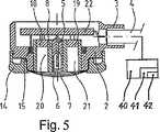
図5−図4の線A−Aに沿って切断したセンサーの断面図である;
図6−図4の線B−Bに沿って切断したセンサーの断面図である;そして
図7−耳たぶに置かれることを意図したセンサー接触面の上面図である。The method of the present invention and the sensor of the present invention will be described below based on various embodiments with reference to the drawings. These are shown in the following figure.
FIG. 1 is a diagram of a measurement curve for measuring transcutaneous CO2 partial pressure in two ear lobes to be tested using a sensor having a sensor contact area, where the sensor contact surface of the sensor is in an earlobe during the initial stage Maintained at a high temperature of 42 ° C;
FIG. 2 is a diagram of a further measurement curve for the measurement of transcutaneous CO2 partial pressure in two ear lobes of the same test subject, in which the sensor contact surface of the sensor is maintained at a high temperature of 43 ° C. during the initial phase. ing;
FIG. 3 is a diagram of a further measurement curve for the measurement of transcutaneous CO2 partial pressure in two ear lobes of the same test subject, where the sensor contact surface of the sensor is maintained at a high temperature of 44 ° C. during the initial stage in one ear lobe. ing;
FIG. 4-is a schematic top view of a sensor of the present invention for measurement of transcutaneous CO2 partial pressure and pulsed oxygen concentration measurement of arterial oxygen saturation;
FIG. 5 is a cross-sectional view of the sensor taken along line AA in FIGS. 5-4;
6 is a cross-sectional view of the sensor taken along line BB of FIG. 6-4; and FIG. 7--top view of a sensor contact surface intended to be placed on the earlobe.
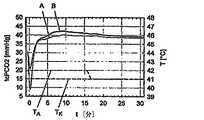
図1−3において、図のX軸は分単位の時間を表し、左のY軸はmmHg単位の分圧であり、そして摂氏度単位の温度が右のY軸に示されている。
試験対象の一つの耳たぶに関して、それぞれの場合において経皮CO2分圧をセンサーにより測定し、その際、センサーの接触面は41℃の一定の温度に維持した。この一定の温度は、それぞれの場合において、破線の水平直線TKとして表されている。対応する経皮CO2分圧の測定値は、図1の測定曲線B、図2の測定曲線D及び図3の測定曲線Fとなった。これらの測定曲線B、D及びFの三つすべてにおいて、測定値が最初におよそ28−35mmHgから約18−23mmHgに鋭く落ち、そしてその後、約42−45mmHgのピークまで上昇してから、これらがゆっくりと38〜42mmHgのおよそ安定した値に落ちるのを観察することができる。1-3, the X-axis in the figure represents time in minutes, the left Y-axis is the partial pressure in mmHg, and the temperature in degrees Celsius is shown on the right Y-axis.
For each earlobe to be tested, the transcutaneous CO2 partial pressure was measured with a sensor in each case, with the sensor contact surface maintained at a constant temperature of 41 ° C. This constant temperature, in each case, are represented as dashed horizontal straight line TK. The corresponding measured values of transdermal CO2 partial pressure were the measurement curve B in FIG. 1, the measurement curve D in FIG. 2, and the measurement curve F in FIG. In all three of these measurement curves B, D and F, the measured values first dropped sharply from approximately 28-35 mmHg to about 18-23 mmHg and then increased to a peak of about 42-45 mmHg before they were It can be observed that it slowly falls to an approximately stable value of 38-42 mmHg.
表示された測定値の初期の鋭い低下は、センサーを較正チャンバーから取出し、耳たぶに置いたことに起因する。これは、最初の3〜5分間の測定は生理学的条件によるものではないので、動脈血CO2分圧の決定のために使用することはできないことを意味する。The initial sharp drop in the displayed measurement is due to the sensor being removed from the calibration chamber and placed on the earlobe. This means that the first 3-5 minute measurement cannot be used for determination of arterial CO2 partial pressure because it is not due to physiological conditions.
その後、最終的に達成されるおよそ安定した値に対して経皮CO2分圧の測定値についてオーバーシュートが起こる;これまでに説明したように、これは、センサー接触面に接触している皮膚が実際に急速に暖められ、これが局所的代謝を高め、こうしてCO2の放出の増大につながるが、その後に皮膚の血管拡張が起こるという事実に起因し得る。これは、皮膚中に代謝的に産生されたCO2は、その後に血管によって除去されるだけであり、そして経皮CO2分圧が最初は過剰であることを意味する。更に、経皮CO2分圧測定のオーバーシュートは、皮膚に蓄えられたCO2によって引き起こされるか又は強められるであろう。Thereafter, overshoot occurs for the measured transdermal CO2 partial pressure relative to the approximately stable value finally achieved; as explained so far, this is the skin in contact with the sensor contact surface There really rapidly warmed, which increases the local metabolism, thus leads to an increase in the emission of CO2, may be due to the fact that subsequent vasodilation of the skin occurs. This means that CO2 produced metabolically in the skin is only subsequently removed by the blood vessels and the transdermal CO2 partial pressure is initially excessive. Furthermore, transcutaneous CO2 partial pressure overshoot may be caused or enhanced by CO2 stored in the skin.
このオーバーシュートを防止するために、本発明によれば、試験対象の他の耳たぶにおけるセンサーのセンサー接触面を、初期段階の間、それぞれ、42℃、43℃及び44℃の高温に維持し、そしてこの初期段階の終了後にはじめてセンサー接触面の温度を41℃まで下げた。図1に示した測定に関して、最初の段階はおよそ16分継続し、そしてセンサー接触面の温度(破線の温度曲線、TA)はこの時間の間42℃であった。その後、センサー接触面の温度を1分間以内に1℃下げた。図2に示した測定に関して、最初の段階はおよそ15.5分継続し、そしてセンサー接触面の温度(破線の温度曲線、TC)はこの時間の間43℃であった。その後、センサー接触面の温度を1分半以内に2℃下げた。図3に示した測定に関して、最初の段階はおよそ18分継続し、そしてセンサー接触面の温度(破線の温度曲線、TE)はこの時間の間44℃であった。その後、センサーの接触面の温度を2分以内に3℃下げた。In order to prevent this overshoot, according to the present invention, the sensor contact surface of the sensor in the other earlobe of the test object is maintained at a high temperature of 42 ° C., 43 ° C. and 44 ° C., respectively, during the initial phase, The temperature of the sensor contact surface was lowered to 41 ° C. only after the completion of this initial stage. For the measurement shown in FIG. 1, the initial phase lasted approximately 16 minutes and the temperature of the sensor interface (dashed temperature curve, TA ) was 42 ° C. during this time. Thereafter, the temperature of the sensor contact surface was lowered by 1 ° C. within 1 minute. For the measurements shown in FIG. 2, the first stage lasted approximately 15.5 minutes and the temperature of the sensor contact surface (dashed temperature curve, TC ) was 43 ° C. during this time. Thereafter, the temperature of the sensor contact surface was lowered by 2 ° C. within 1 minute and a half. For the measurements shown in FIG. 3, the initial phase lasted approximately 18 minutes and the temperature of the sensor interface (dashed temperature curve, TE ) was 44 ° C. during this time. Thereafter, the temperature of the contact surface of the sensor was lowered by 3 ° C. within 2 minutes.
温度曲線TA、TC及びTEに関連する経皮CO2分圧の測定値は、図1の測定曲線A、図2の測定曲線C及び図3の測定曲線Eとなった。これらの測定曲線A、C及びEの三つすべてにおいて、測定値が最初に30−35mmHgから約8−28mmHgに鋭く落ち、そしてその後、約38〜42mmHgのおよそ安定した値まで急速に上昇するのを観察することができる。最後に達するおよそ安定した値を超える経皮CO2分圧の測定のオーバーシュートは見られない。これは、およそ5分の比較的短い準備段階の後で測定がすでに使用可能であることを意味する。The measured values of the transcutaneous CO2 partial pressure related to the temperature curves TA , TC and TE were the measurement curve A in FIG. 1, the measurement curve C in FIG. 2, and the measurement curve E in FIG. In all three of these measurement curves A, C and E, the measured value first sharply drops from 30-35 mmHg to about 8-28 mmHg and then rapidly rises to an approximately stable value of about 38-42 mmHg. Can be observed. There is no overshoot in the measurement of the transcutaneous CO2 partial pressure above the approximately stable value reached at the end. This means that the measurement is already available after a relatively short preparation phase of approximately 5 minutes.
図4−7は、動脈血酸素飽和度のパルス式酸素濃度測定を同時に行うことができる、経皮CO2分圧の測定のための本発明のセンサーの一態様を示す。図4は、センサー1の上面図を示し、図中には、図5(A−A)及び図6(B−B)の断面図の切断面が描かれている。センサーヘッドは、首型の延長部3を伴うプラスチックで作られた円形のハウジング2からなり、それを通して接続ワイヤー4が図5において略図的に表される測定装置40に導かれる。測定機能のために必要とされる部品及び以下に説明する種々の電子部品がハウジング内に含有されている。4-7 illustrate one embodiment of the sensor of the present invention for the measurement of transcutaneous CO2 partial pressure that allows simultaneous pulsed oxygen concentration measurements of arterial oxygen saturation. FIG. 4 shows a top view of the
ガラス製pH電極5は、センサーの中心線に見出される。これは、その前面側にpH感受性のガラス層6が融合されている円筒形のガラス製シャフトからなる。ガラス製円筒の内部には、ガラス中に融合された白金製の引き込みワイヤー7を備えた内部参照電極がある。pH電極5は、その表面が塩化物層9で被覆された銀製ブロック8中に埋め込まれている。銀製ブロックの表面は、このようにAg/AgCl電極を形成し、これがpH測定のための参照電極として働く。そのpH値が測定された電解質溶液が、ガス透過性の疎水性膜11(テフロン(登録商標)など)で被覆された、多孔質の親水性スペーサー10中に配置される。膜を機械的損傷から保護するために、この膜は金属製保護板12で被覆されている。この保護板は、中央(pH感受性ガラス層6の上)に開口部13を有し、これを通して測定されるべきCO2ガスが、pH感受性のガラス層の領域において電解質溶液中に拡散することができる。スペーサー10、膜11及び金属製保護板12は、センサーの鋳型2にテンションリング14によって固定されている。銀製ブロック8は、更に加熱器としても機能する。銀製ブロックは加熱用ワイヤー15で糸巻きのように巻かれ、それにより、経皮的測定のために必要とされる37℃〜45℃の温度に加熱される。図6において見ることができるように、銀製ブロック8内部の二つのボアホール中に組込まれた二つのサーミスター16及び17が存在する。これらのサーミスター16、17は、選択されたセンサーの温度を調節及び制御するために働く。センサー接触面の温度は、通常低いが、サーミスター16、17によって測定された温度から計算してもよい。計算に使用される温度勾配は、センサー接触面における温度を測定することによって前もって決定することができ、この場合、温度測定は、国際的標準IEC60601−2−23、Clause 42.3.104に従う。A
パルス式酸素濃度測定のために必要な光学的部品は、図5の断面図中で見ることができる。セラミック製基板上に互いに隣接して直接設置された二つのLED18及びフォトダイオード19が存在する。これらの部品から及びこれらへの光は、銀製ブロック中の半透明の物質で満たされた二つの孔からなる、二つの円筒形の光チャンネル20及び21によって導かれる。 The optical components necessary for pulse oximetry can be seen in the cross-sectional view of FIG. There are two
種々の部品から及びこれらへのすべての電気的接続は電子ユニット22に入り、ここで信号処理の一部が既に行われる。測定装置40への接続ワイヤー4は、この電子ユニットから始まり、そして説明したようにセンサーの首部3を通って外部へ進む。測定装置40は、タイマー42を備えた加熱制御ユニット41を有し、この加熱制御ユニットにより、本発明に従って、調節可能な所定の時間後、銀製ブロック8及び加熱用ワイヤー15によって構成される加熱器の加熱器電力を下げることができる。 All electrical connections from and to the various components enter the
最後に、図7は、センサーの実際の接触面25を形成する金属製保護板12の上面図を示す。既に述べたように、開口部13は保護板の中心に位置し、これを経由して二酸化炭素ガスがpH電極において電解質に達することができる。周辺に配列された二つの開口部23及び24は、LEDから出る光や組織からの散乱光が通過することを可能にする。 Finally, FIG. 7 shows a top view of the
これまでに説明した本発明の方法及びセンサーの更なる態様を実施することができる。センサーは、もちろんのことながら、動脈血酸素飽和度のパルス式酸素濃度測定を行うための部品を有する必要はないことをここに明白に注記しておく。更に、測定のための全体の電子回路もセンサーのヘッド自体の中に置いてもよい。 Further embodiments of the methods and sensors of the invention described so far can be implemented. It is expressly noted here that the sensor need not of course have parts for performing a pulsed oximetry of arterial oxygen saturation. Furthermore, the entire electronic circuit for the measurement may also be placed in the sensor head itself.
Claims (13)
Translated fromJapanese初期段階の間は該センサー接触面を少なくとも41.5℃の高温に維持し、そして、その後に、該センサー接触面の温度を、1分あたり6℃未満又はそれに等しい速度で、37℃〜41℃に下げることを特徴とする、前記方法。By means of a sensor (1) comprising a measuring device for measuring transcutaneous CO2 partial pressure and a heating element (8, 15) for warming the sensor contact surface (25) intended to be brought into contact with the earlobe. A method for measuring transcutaneous CO2 partial pressure in
During the initial phase, the sensor contact surface is maintained at a high temperature of at least 41.5 ° C., and thereafter the temperature of the sensor contact surface is reduced from 37 ° C. to 41 ° at a rate of less than or equal to 6 ° C. per minute. Said method, characterized in that it is lowered to ° C.
経皮CO2分圧のための測定部位における皮膚を初期段階の間少なくとも41.5℃の高温に維持し、そして、その後に、該皮膚の温度を、1分あたり6℃未満又はそれに等しい速度で、37℃〜41℃の間まで低下させる、前記方法。Method for preventing transcutaneous CO2 partial pressure in earlobe skin from increasing during arterialization of the skin associated with measurement of transcutaneous CO2 partial pressure relative to CO2 partial pressure achieved after stabilization Because
The skin at the measurement site for transdermal CO2 partial pressure is maintained at a high temperature of at least 41.5 ° C. during the initial phase, and then the temperature of the skin is reduced to a rate of less than or equal to 6 ° C. per minute And reducing the temperature to between 37 ° C and 41 ° C.
Applications Claiming Priority (3)
| Application Number | Priority Date | Filing Date | Title |
|---|---|---|---|
| CH8672004 | 2004-05-18 | ||
| CH867/04 | 2004-05-18 | ||
| PCT/CH2005/000265WO2005110221A1 (en) | 2004-05-18 | 2005-05-12 | Process for measuring partial transcutaneous co2 pressure at an ear lobe |
Publications (2)
| Publication Number | Publication Date |
|---|---|
| JP2007537799A JP2007537799A (en) | 2007-12-27 |
| JP4558041B2true JP4558041B2 (en) | 2010-10-06 |
Family
ID=34965915
Family Applications (1)
| Application Number | Title | Priority Date | Filing Date |
|---|---|---|---|
| JP2007516928AExpired - Fee RelatedJP4558041B2 (en) | 2004-05-18 | 2005-05-12 | Method for measuring transcutaneous CO2 partial pressure in the earlobe |
Country Status (7)
| Country | Link |
|---|---|
| US (1) | US7474908B2 (en) |
| EP (1) | EP1753343B9 (en) |
| JP (1) | JP4558041B2 (en) |
| CN (1) | CN100471451C (en) |
| DK (1) | DK1753343T3 (en) |
| ES (1) | ES2401647T3 (en) |
| WO (1) | WO2005110221A1 (en) |
Families Citing this family (12)
| Publication number | Priority date | Publication date | Assignee | Title |
|---|---|---|---|---|
| US20100212666A1 (en)* | 2006-06-21 | 2010-08-26 | Universitat Bern | System for Controlling Administration of Anaesthesia |
| WO2007147505A2 (en)* | 2006-06-21 | 2007-12-27 | Universität Bern | A system for controlling administration of anaesthesia |
| WO2011024018A1 (en)* | 2009-08-28 | 2011-03-03 | Assistance Publique - Hopitaux De Paris | A non-invasive method for assessing tissue perfusion in a patient |
| FR3001626B1 (en)* | 2013-02-05 | 2015-04-24 | Hopitaux Paris Assist Publique | NON-INVASIVE METHOD FOR MEASURING THE STATE OF TISSUE PERFUSION |
| US20160029973A1 (en)* | 2013-06-13 | 2016-02-04 | Koninklijke Philips N.V. | Device and method for determining a partial carbon dioxide pressure in a subject of interest |
| EP3795072B1 (en)* | 2014-07-15 | 2024-09-18 | Radiometer Basel AG | Intermittent measuring of the partial pressure of an analyte in the skin tissue |
| CA2973261A1 (en) | 2015-01-09 | 2016-07-14 | Exhalix Llc | Transdermal sampling strip and method for analyzing transdermally emitted gases |
| CN108013866A (en)* | 2016-11-02 | 2018-05-11 | 北京大学 | A kind of new sign data detection method and wearable sign detection device |
| US20190261897A1 (en)* | 2017-11-28 | 2019-08-29 | Alan D. Kersey | Apparatus and method for assessment of cancer margin |
| CN109770848B (en)* | 2018-12-03 | 2022-09-16 | 新绎健康科技有限公司 | Device and method for measuring carbon dioxide release rate |
| CN111103158B (en)* | 2019-12-18 | 2021-11-16 | 广电计量检测(深圳)有限公司 | Calibration device and method for percutaneous partial pressure monitor |
| CN114983401A (en)* | 2022-04-20 | 2022-09-02 | 北京秋满实医疗科技有限公司 | Sensor for measuring the transcutaneous partial pressure of oxygen at a body part of a patient |
Family Cites Families (6)
| Publication number | Priority date | Publication date | Assignee | Title |
|---|---|---|---|---|
| CA1131708A (en)* | 1978-09-11 | 1982-09-14 | Wolfgang Mindt | Electrode for cutaneous po2 measurement |
| WO1983001510A1 (en)* | 1981-10-13 | 1983-04-28 | Baumbach, Per, Lennart | Method for transcutaneous measurement of a blood parameter and an electrochemical measuring electrode device for carrying out the method |
| US4586149A (en)* | 1983-07-05 | 1986-04-29 | Sensormedics Corporation | Temperature control system for cutaneous gas monitor |
| EP0252263B1 (en)* | 1986-06-06 | 1992-08-05 | Kontron Instruments Holding N.V. | Electrodes arrangement |
| US4805122A (en)* | 1986-12-31 | 1989-02-14 | Sensormedics Corporation | Temperature control system for cutaneous gas monitor |
| CA2290083A1 (en)* | 1999-11-19 | 2001-05-19 | Linde Medical Sensors Ag. | Device for the combined measurement of the arterial oxygen saturation and the transcutaneous co2 partial pressure of an ear lobe |
- 2005
- 2005-05-12JPJP2007516928Apatent/JP4558041B2/ennot_activeExpired - Fee Related
- 2005-05-12USUS11/596,873patent/US7474908B2/ennot_activeExpired - Lifetime
- 2005-05-12WOPCT/CH2005/000265patent/WO2005110221A1/enactiveApplication Filing
- 2005-05-12DKDK05735964.8Tpatent/DK1753343T3/enactive
- 2005-05-12CNCNB2005800242014Apatent/CN100471451C/ennot_activeExpired - Fee Related
- 2005-05-12EPEP05735964Apatent/EP1753343B9/ennot_activeExpired - Lifetime
- 2005-05-12ESES05735964Tpatent/ES2401647T3/ennot_activeExpired - Lifetime
Also Published As
| Publication number | Publication date |
|---|---|
| US7474908B2 (en) | 2009-01-06 |
| JP2007537799A (en) | 2007-12-27 |
| DK1753343T3 (en) | 2013-02-04 |
| CN1988849A (en) | 2007-06-27 |
| EP1753343B9 (en) | 2013-03-13 |
| ES2401647T3 (en) | 2013-04-23 |
| WO2005110221A1 (en) | 2005-11-24 |
| US20080064942A1 (en) | 2008-03-13 |
| CN100471451C (en) | 2009-03-25 |
| EP1753343A1 (en) | 2007-02-21 |
| EP1753343B1 (en) | 2012-12-19 |
Similar Documents
| Publication | Publication Date | Title |
|---|---|---|
| EP3795072B1 (en) | Intermittent measuring of the partial pressure of an analyte in the skin tissue | |
| JP4558041B2 (en) | Method for measuring transcutaneous CO2 partial pressure in the earlobe | |
| US6654622B1 (en) | Device for the combined measurement of the arterial oxygen saturation and the transcutaneous CO2 partial pressure on an ear lobe | |
| CA1043125A (en) | Measurement of partial pressure of gases diffusing through skin | |
| TW201012434A (en) | Systems for characterizing physiologic parameters and methods for use therewith | |
| JP2010194343A (en) | System and method for continuous analyte monitoring | |
| Vesterager | Transcutaneous pO2 electrode | |
| JP5243719B2 (en) | Biological signal measuring tool and biological signal measuring method using the same | |
| Eberhard | Continuous oxygen monitoring of newborns by skin sensors | |
| Seylaz et al. | Techniques for continous measurement of local cerebral blood flow, Pa O2, Pa CO2 and blood pressure in the non-anesthetized animal | |
| EP3232928B1 (en) | Apparatus and method for non-invasively determining the concentration of an analyte | |
| JPS6331638A (en) | Non-invasive biochemical substance measuring device | |
| Eberhard et al. | Reliability of cutaneous oxygen measurement by skin sensors with large‐size cathodes | |
| JP7711332B1 (en) | Transcutaneous carbon dioxide measuring device | |
| Lübbers et al. | Problems of transcutaneous measurement of arterial blood gases | |
| JPS6131123A (en) | Adhesive disk for transcutaneous blood gas concentration measurement sensor | |
| SE545316C2 (en) | Sampling unit, system and method for transcutaneous blood gas monitoring | |
| JPS6142568Y2 (en) | ||
| JPS6143450Y2 (en) | ||
| JPS5931217Y2 (en) | Calibration device for transcutaneous blood oxygen partial pressure measurement sensor | |
| WO2001056463A1 (en) | Method of monitoring conjunctival systemic parameters | |
| WO2003090615A1 (en) | Method and apparatus for noninvasive measuring of transcutaneous oxygen uptake | |
| JPS61135645A (en) | Transcutaneous sensor | |
| JPS6185926A (en) | Transmucosal blood gas sensor |
Legal Events
| Date | Code | Title | Description |
|---|---|---|---|
| A131 | Notification of reasons for refusal | Free format text:JAPANESE INTERMEDIATE CODE: A131 Effective date:20091218 | |
| A521 | Request for written amendment filed | Free format text:JAPANESE INTERMEDIATE CODE: A523 Effective date:20100318 | |
| A131 | Notification of reasons for refusal | Free format text:JAPANESE INTERMEDIATE CODE: A131 Effective date:20100428 | |
| A521 | Request for written amendment filed | Free format text:JAPANESE INTERMEDIATE CODE: A523 Effective date:20100527 | |
| TRDD | Decision of grant or rejection written | ||
| A01 | Written decision to grant a patent or to grant a registration (utility model) | Free format text:JAPANESE INTERMEDIATE CODE: A01 Effective date:20100621 | |
| A01 | Written decision to grant a patent or to grant a registration (utility model) | Free format text:JAPANESE INTERMEDIATE CODE: A01 | |
| A61 | First payment of annual fees (during grant procedure) | Free format text:JAPANESE INTERMEDIATE CODE: A61 Effective date:20100720 | |
| R150 | Certificate of patent or registration of utility model | Ref document number:4558041 Country of ref document:JP Free format text:JAPANESE INTERMEDIATE CODE: R150 Free format text:JAPANESE INTERMEDIATE CODE: R150 | |
| FPAY | Renewal fee payment (event date is renewal date of database) | Free format text:PAYMENT UNTIL: 20130730 Year of fee payment:3 | |
| R250 | Receipt of annual fees | Free format text:JAPANESE INTERMEDIATE CODE: R250 | |
| R250 | Receipt of annual fees | Free format text:JAPANESE INTERMEDIATE CODE: R250 | |
| R250 | Receipt of annual fees | Free format text:JAPANESE INTERMEDIATE CODE: R250 | |
| R250 | Receipt of annual fees | Free format text:JAPANESE INTERMEDIATE CODE: R250 | |
| R250 | Receipt of annual fees | Free format text:JAPANESE INTERMEDIATE CODE: R250 | |
| R250 | Receipt of annual fees | Free format text:JAPANESE INTERMEDIATE CODE: R250 | |
| R250 | Receipt of annual fees | Free format text:JAPANESE INTERMEDIATE CODE: R250 | |
| R250 | Receipt of annual fees | Free format text:JAPANESE INTERMEDIATE CODE: R250 | |
| R250 | Receipt of annual fees | Free format text:JAPANESE INTERMEDIATE CODE: R250 | |
| R250 | Receipt of annual fees | Free format text:JAPANESE INTERMEDIATE CODE: R250 | |
| R250 | Receipt of annual fees | Free format text:JAPANESE INTERMEDIATE CODE: R250 | |
| LAPS | Cancellation because of no payment of annual fees |