JP4557331B2 - Information processing apparatus, information processing system, operation control method, and computer-readable recording medium - Google Patents
Information processing apparatus, information processing system, operation control method, and computer-readable recording mediumDownload PDFInfo
- Publication number
- JP4557331B2 JP4557331B2JP14072999AJP14072999AJP4557331B2JP 4557331 B2JP4557331 B2JP 4557331B2JP 14072999 AJP14072999 AJP 14072999AJP 14072999 AJP14072999 AJP 14072999AJP 4557331 B2JP4557331 B2JP 4557331B2
- Authority
- JP
- Japan
- Prior art keywords
- setting
- information processing
- digital camera
- processing apparatus
- screen
- Prior art date
- Legal status (The legal status is an assumption and is not a legal conclusion. Google has not performed a legal analysis and makes no representation as to the accuracy of the status listed.)
- Expired - Fee Related
Links
Images


Classifications
- G—PHYSICS
- G06—COMPUTING OR CALCULATING; COUNTING
- G06F—ELECTRIC DIGITAL DATA PROCESSING
- G06F3/00—Input arrangements for transferring data to be processed into a form capable of being handled by the computer; Output arrangements for transferring data from processing unit to output unit, e.g. interface arrangements
- G06F3/002—Specific input/output arrangements not covered by G06F3/01 - G06F3/16
- G06F3/005—Input arrangements through a video camera
- H—ELECTRICITY
- H04—ELECTRIC COMMUNICATION TECHNIQUE
- H04N—PICTORIAL COMMUNICATION, e.g. TELEVISION
- H04N23/00—Cameras or camera modules comprising electronic image sensors; Control thereof
- H04N23/60—Control of cameras or camera modules
- H04N23/63—Control of cameras or camera modules by using electronic viewfinders
- H04N23/631—Graphical user interfaces [GUI] specially adapted for controlling image capture or setting capture parameters
- H—ELECTRICITY
- H04—ELECTRIC COMMUNICATION TECHNIQUE
- H04N—PICTORIAL COMMUNICATION, e.g. TELEVISION
- H04N1/00—Scanning, transmission or reproduction of documents or the like, e.g. facsimile transmission; Details thereof
- H04N1/00127—Connection or combination of a still picture apparatus with another apparatus, e.g. for storage, processing or transmission of still picture signals or of information associated with a still picture
- H04N1/00347—Connection or combination of a still picture apparatus with another apparatus, e.g. for storage, processing or transmission of still picture signals or of information associated with a still picture with another still picture apparatus, e.g. hybrid still picture apparatus
- H—ELECTRICITY
- H04—ELECTRIC COMMUNICATION TECHNIQUE
- H04N—PICTORIAL COMMUNICATION, e.g. TELEVISION
- H04N1/00—Scanning, transmission or reproduction of documents or the like, e.g. facsimile transmission; Details thereof
- H04N1/0035—User-machine interface; Control console
- H04N1/00498—Multi-lingual facilities
- H—ELECTRICITY
- H04—ELECTRIC COMMUNICATION TECHNIQUE
- H04N—PICTORIAL COMMUNICATION, e.g. TELEVISION
- H04N23/00—Cameras or camera modules comprising electronic image sensors; Control thereof
- H04N23/60—Control of cameras or camera modules
- H04N23/62—Control of parameters via user interfaces
- H—ELECTRICITY
- H04—ELECTRIC COMMUNICATION TECHNIQUE
- H04N—PICTORIAL COMMUNICATION, e.g. TELEVISION
- H04N23/00—Cameras or camera modules comprising electronic image sensors; Control thereof
- H04N23/60—Control of cameras or camera modules
- H04N23/66—Remote control of cameras or camera parts, e.g. by remote control devices
- H04N23/661—Transmitting camera control signals through networks, e.g. control via the Internet
- H—ELECTRICITY
- H04—ELECTRIC COMMUNICATION TECHNIQUE
- H04N—PICTORIAL COMMUNICATION, e.g. TELEVISION
- H04N23/00—Cameras or camera modules comprising electronic image sensors; Control thereof
- H04N23/60—Control of cameras or camera modules
- H04N23/667—Camera operation mode switching, e.g. between still and video, sport and normal or high- and low-resolution modes
- H—ELECTRICITY
- H04—ELECTRIC COMMUNICATION TECHNIQUE
- H04N—PICTORIAL COMMUNICATION, e.g. TELEVISION
- H04N2101/00—Still video cameras
- H—ELECTRICITY
- H04—ELECTRIC COMMUNICATION TECHNIQUE
- H04N—PICTORIAL COMMUNICATION, e.g. TELEVISION
- H04N2201/00—Indexing scheme relating to scanning, transmission or reproduction of documents or the like, and to details thereof
- H04N2201/0008—Connection or combination of a still picture apparatus with another apparatus
- H04N2201/0072—Detecting the status of a connected apparatus
Landscapes
- Engineering & Computer Science (AREA)
- Multimedia (AREA)
- Signal Processing (AREA)
- Human Computer Interaction (AREA)
- Theoretical Computer Science (AREA)
- Physics & Mathematics (AREA)
- General Engineering & Computer Science (AREA)
- General Physics & Mathematics (AREA)
- Studio Devices (AREA)
- User Interface Of Digital Computer (AREA)
Description
Translated fromJapanese【0001】
【発明の属する技術分野】
本発明は、例えば、ディジタルカメラや携帯情報端末装置(PDA:Personal Digital Assistants 、以下、「携帯端末装置」とも言う)等の端末装置と、パーソナルコンピュータ等のコンピュータ装置との間で、データ通信や情報表示するための技術に関するものである。
【0002】
【従来の技術】
従来より例えば、画像や文字等のデータを入力及び表示するようになされたディジタルカメラやPDA(携帯端末装置)等の端末装置と、データを記録及び表示するようになされたコンピュータ装置とを接続し、端末装置からコンピュータ装置へ、或いはコンピュータ装置から端末装置ヘとデータを転送することのできるようになされたシステムがある。
【0003】
ここで、上述の端末装置、例えば、現在市販されているディジタルカメラには、RS−232C規格のシリアル通信ポートが装備されているのが一般的である。これにより、ディジタルカメラのシリアル通信ポートを、コンピュータ装置のシリアル通信ポートに直接接続することで、相互のデータ転送を行うことができる。
このような端末装置とコンピュータ装置の接続手段としては、上記のシリアル通信の他にパラレル通信、或いは赤外線通信等が一般的に用いられている。
【0004】
また、上述の端末装置としては、物理的なスイッチや、或いは表示部に表示されるメニュー等の手段によって、データの入力、データ転送、一覧表示等の動作モードを切り替えることのできる端末装置がある。
【0005】
具体的には例えば、撮影モードと通信モードの切り替えスイッチを備えるディジタルカメラがある。このディジタルカメラは、主に次のような構成としている。
・撮影モードでは、レリーズボタンが押下されることでデータの入力(すなわち、画像を得るための撮影動作)を行うが、このとき、コンピュータ装置との間でのデータの転送は行わない。一方、通信モードでは、コンピュータ装置との間でのデータの転送は行うが、このとき、撮影動作は行わない。
・動作モードの切り替えに従って、通信モードではレリーズボタンを無効にする等の構成をとる。これにより、誤操作を防ぐことができる。
・ある1つの操作スイッチの機能を、動作モードの切り替えに従って切り替えることで、1つの操作スイッチに複数の機能を持たせる。これにより、操作スイッチの総数を減少させることができる。
【0006】
また、次のような構成のディジタルカメラもある。
・表示部としての液晶画面にメニューを表示し、該メニュー上からの表示言語(日本語、英語等)の設定に従って、液晶画面でのメニューや情報の表示等に使用される言語を、全て設定された言語に切り替える。これにより、1台のディジタルカメラを様々な地域で使用することができる。
【0007】
一方、コンピュータ装置や、コンピュータ装置で用いられるアプリケーションソフトウェアには、設定を変更することにより、データの表示方法を変更できるものがある。
例えば、米国Microsoft社の”Windows”には、表示言語(日本語、英語等)を設定する機能があり、この機能によって表示言語を変更すると、Windows上で動作するアプリケーションソフトウェアのユーザインタフェースで使用される言語が変更される。
【0008】
また、コンピュータ装置において、本装置に上述したような端末装置が接続されると、この接続を検出し、さらに接続された端末装置の状態をも検知し、さらにまた端末装置の状態が変化すると、その状態の変化を検知することができる機能を有するコンピュータ装置がある。
例えば、USB(Universal Serial Bus)を装備したパーソナルコンピュータ(以下、単に「PC」又は「パソコン」と言う)に、米国Microsoft社の”Windows98”を搭載したものでは、USBに接続された機器の状態を検出することができるようになされている。
【0009】
【発明が解決しようとする課題】
しかしながら、上述したような従来のコンピュータ装置、特に、システム設定を変更することで、データの表示方法を変更できる従来のコンピュータ装置では、複数の利用者がいる場合、それぞれの利用者が自分の希望する設定で表示を行なおうとすると、それぞれの利用者は、前の利用者の設定を自分の設定に切り替えるための操作が必要となる。また、これまで使用したことのないコンピュータ装置を初めて使用するときにも、この操作が必要となる。
すなわち、従来では、最初にコンピュータ装置を使用する場合や、それぞれ異なった設定を使用している複数の利用者が1つのコンピュータ装置を交互に使用する場合には、毎回コンピュータ装置の設定を変更する必要があった。
【0011】
そこで、本発明は、利用者が情報処理装置において表示言語の設定を変更する操作を行うことなく、情報処理装置の表示言語の設定を変更できるようにすることを目的とする。
【0012】
【課題を解決するための手段】
本発明の情報処理装置は、外部機器と通信可能に接続される情報処理装置であって、前記外部機器が接続されたことを検出する接続検出手段と、前記接続検出手段によって前記外部機器が接続されたと検出されると、前記外部機器における設定のうち前記情報処理装置に設定可能な表示言語の設定を自動的に検出する設定検出手段と、前記設定検出手段によって前記設定が検出されると、前記情報処理装置に予め与えられていた表示言語の設定を前記設定検出手段によって検出された表示言語の設定に応じて自動的に変更する設定変更手段とを有することを特徴とする。
本発明の情報処理システムは、複数の機器が通信可能に接続されてなる情報処理システムであって、前記複数の機器のうち少なくとも1つの機器は、本発明の情報処理装置の機能を有することを特徴とする。
本発明の情報処理装置の動作制御方法は、外部機器と通信可能に接続される情報処理装置の動作制御方法であって、前記外部機器が接続されたことを検出する接続検出ステップと、前記接続検出ステップによって前記外部機器が接続されたと検出されると、前記外部機器における設定のうち前記情報処理装置に設定可能な表示言語の設定を自動的に検出する設定検出ステップと、前記設定検出ステップによって前記設定が検出されると、前記情報処理装置に予め与えられていた表示言語の設定を前記設定検出ステップによって検出された表示言語の設定に応じて自動的に変更する設定変更ステップとを有することを特徴とする。
本発明のコンピュータ読み取り可能な記録媒体は、外部機器と通信可能に接続される情報処理装置を、前記外部機器が接続されたことを検出する接続検出手段と、前記接続検出手段によって前記外部機器が接続されたと検出されると、前記外部機器における設定のうち前記情報処理装置に設定可能な表示言語の設定を自動的に検出する設定検出手段と、前記設定検出手段によって前記設定が検出されると、前記情報処理装置に予め与えられていた表示言語の設定を前記設定検出手段によって検出された表示言語の設定に応じて自動的に変更する設定変更手段として機能させるためのプログラムを記録したことを特徴とする。
【0035】
【発明の実施の形態】
以下、本発明の実施の形態について図面を用いて説明する。
【0036】
(第1の実施の形態)
本発明は、例えば、図1に示すようなデータ通信システム100に適用される。
このデータ通信システム100では、外部機器としてのディジタルカメラ200と情報処理装置としてのコンピュータ装置300とが接続可能なようになされている。
ディジタルカメラ200は、携帯端末装置であり、入力されたデータ(撮影して得られた画像データ等)を、コンピュータ装置300に対して、USBケーブル400を介して転送するようになされている。
また、コンピュータ装置300は、ディジタルカメラ200から転送されてきたデータを、後述する表示装置で一覧表示できるようになされている。
以下、データ通信システム100におけるディジタルカメラ200及びコンピュータ装置300について具体的に説明する。
【0037】
[ディジタルカメラ200の構成]
図2(a)及び(b)は、ディジタルカメラ200の前面(同図(a))及び背面(同図(b))からみた構成を示したものである。
【0038】
まず、上記図2(a)に示すように、ディジタルカメラ200の前面には、撮像レンズ201が設けられており、その内部には、CCD(Charge Coupled Device)202が設けられている。
CCD202は、データ入力手段として設けられたものであり、撮像レンズ201を介した被写体光を撮像して、その画像信号を出力するようになされている。
一方、上記図2(b)に示すように、ディジタルカメラ200の背面には、データ表示手段としての液晶モニタ203、メニューボタン205、セットボタン206、+ボタン207、及び−ボタン208が設けられている。
また、ディジタルカメラ200上面及び側面には、レリーズボタン209が設けられていると共に、データ転送手段としてのUSBコネクタ204が1基設けられている。
【0039】
上述のようなディジタルカメラ200では、メニューボタン205を押下することで、液晶モニタ203に表示されるメニュー画面上から表示言語の設定を行うことができるようになされている。
図3(a)及び(b)は、このときの表示言語の設定のためのメニュー画面の一例を示したものである。
上記図3(a)に示すメニュー画面上で「言語」の項目を選択すると、同図(b)に示すような表示言語の設定のための画面に移行する。この画面上にて、「English」、「Deutsch」、「Fran?ais」、「日本語」等の各種言語の中から所望する言語(ここでは「日本語」)を選択できるようになされている。
このような表示言語の設定により、例えば、「English」を選択し設定すると、その後からの液晶モニタ203での表示は、図4(a)及び(b)に示すように、英語表示されることになる。この図4(a)及び(b)は、上記図3(a)及び(b)に対応する表示言語の設定のためのメニュー画面を示している。
【0040】
[コンピュータ装置300の構成]
【0041】
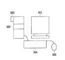
コンピュータ装置300は、例えば、図5に示すように、データ表示手段としてのCRTモニタ301と、データ記録手段としてのハードディスクドライブ302と、データ転送手段としてのUSBコネクタ303とを備えている。また、コンピュータ装置300は、各種操作のためのキーボード304及びマウス305をも備えている。
【0042】
また、コンピュータ装置300では、画像取込ソフトウェアが起動されるようになされており、これにより、USBコネクタ303の先にデジタルカメラ200が接続されると、デジタルカメラ200から画像データを取り込んで、それをCRTモニタ301で表示することが可能となる。
このような画像取り込みソフトウェアでは、設定によって表示言語を切り替えることができるようになされている。
【0043】
図6は、上記の画像取込ソフトウェアによってCRTモニタ301へ表示される画面の一例を示したものである。この図6の画面は、表示言語が日本語に設定されたときの状態を示している。この表示言語が、例えば、英語に設定されると、図7のような英語表示の画面状態となる。
【0044】
ここで、コンピュータ装置300は、ディジタルカメラ200での表示言語の設定を検出し、この検出結果に従って、自装置での表示言語の設定を自動的に行うようになされている。
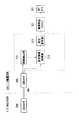
このため、コンピュータ装置300は、例えば、図8に示すように、USBコネクタ303の先にデジタルカメラ200が接続されたことを検出する接続検出部311と、接続検出部311の検出結果に基づいてディジタルカメラ200での表示言語の設定情報を取得する設定情報取得部312と、設定情報取得部312にて得られた設定情報に基づいて上述した画像取込ソフトウェア321での表示言語の設定を変更する設定変更部313とを備えている。
これらの各構成部311〜313は、例えば、コンピュータ装置300内部のCPU(図示せず)により実現される。
【0045】
図9は、上記図8に示した構成により実施されるコンピュータ装置300の動作を示したものである。
【0046】
先ず、接続検出部311は、ディジタルカメラ200がUSBコネクタ303を介して接続されているか否か判別する(ステップS501)。この判別結果により、ディジタルカメラ200が接続されていない場合、再度本ステップ処理を実行する。
【0047】
ステップS501での判別の結果、ディジタルカメラ200が接続されている場合、設定情報取得部312は、ディジタルカメラ200での表示言語の設定情報(設定値)を取得する(ステップS502)。
【0048】
そして、設定変更部313は、設定情報取得部312にて得られた設定情報に基づいて、画像取込ソフトウェア321での表示言語の設定を変更する(ステップS503)。
これにより、例えば、ディジタルカメラ200での表示言語が、上記図4(a)及び(b)に示したような英語の表示言語に設定されていた場合、コンピュータ装置300での表示言語も、上記図7に示したような英語の表示言語に自動的に変更されることになる。 その後、ステップS501へ戻り、以降の処理ステップを繰り返し実行する。
【0049】
上述のように、本実施の形態では、コンピュータ装置300が、ディジタルカメラ200での表示言語の設定を検知して、コンピュータ装置300で動作するソフトウェアの表示言語を自動的に変更するように構成したので、利用者は、自分の希望する表示言語を自分のディジタルカメラ200に設定しておくことで、コンピュータ装置300で表示言語を設定するための操作を行うことなく、自分の希望する表示言語でコンピュータ装置300を利用することができる。これは、複数の利用者が1つのコンピュータ装置300を共同で使用する場合や、利用者がコンピュータ装置300を初めて使用する場合等に特に有効である。
【0050】
尚、上述した実施の形態では、説明の簡単のために、画像取込ソフトウェア321での表示言語の設定を変更するようにしたが、表示言語の設定を変更するソフトウェアとしては、コンピュータ装置300にて起動されるものであれば、画像取込ソフトウェア321に限定されることはない。
【0051】
(第2の実施の形態)
本実施の形態では、上述した第1の実施の形態におけるデータ通信システム100において、ディジタルカメラ200にて設定されている後述する動作モードにおけるディジタルカメラ200の操作の説明の画面を、コンピュータ装置300のCRTモニタ301に表示する。
【0052】
ここでのディジタルカメラ200は、例えば、図10(a)及び(b)に示すように、上記図2(a)及び(b)に示した構成に加えて、モード切替スイッチ211が設けられていると共に、レリーズボタン209の押下により撮影して得られた画像データ及び受信した画像データを記憶するメモリ212が内蔵された構成としている。
そして、ディジタルカメラ200は、モード切替スイッチ211により、カメラの動作モードを、例えば、<送信モード>、<受信モード>、<撮影モード>、<再生モード>の中から所望する動作モードを選択して設定できるようになされている。
【0053】
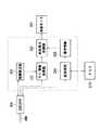
また、ここでのコンピュータ装置300は、例えば、図11に示すように、USBコネクタ303の先にデジタルカメラ200が接続されたことを検出する接続検出部321と、接続検出部321の検出結果に基づいてディジタルカメラ200での動作モードの設定情報を取得するモード情報取得部322と、設定情報取得部322にて得られた設定情報に基づいた操作の画面情報をCRTモニタ301に表示させる画面表示制御部323とを備えている。
これらの各構成部321〜323は、例えば、コンピュータ装置300内部のCPU(図示せず)により実現される。
【0054】
図12は、上記図11に示した構成により実施されるコンピュータ装置300の動作を示したものである。
【0055】
先ず、接続検出部321は、ディジタルカメラ200がUSBコネクタ303を介して接続されているか否か判別する(ステップS511)。この判別結果により、ディジタルカメラ200が接続されていない場合、再度本ステップ処理を実行する。
【0056】
ステップS511での判別の結果、ディジタルカメラ200が接続されている場合、モード情報取得部322は、ディジタルカメラ200の動作モード情報(動作モードの設定値)を取得する。
そして、画面表示制御部323は、モード情報取得部322にて得られたモード情報に基づいて、次のようなステップS513〜S514の処理を実行する(ステップS512)。
【0057】
ステップS513:
ディジタルカメラ200の動作モードが<受信モード>に設定されていた場合、この場合のディジタルカメラ200の操作の説明の画面を、CRTモニタ301に表示させる。このとき、CRTモニタ301に表示する画面情報としては、例えば、メモリ324に予め用意されている、図13(a)に示すような操作画面情報を用いる。したがって、この場合には、上記図13(a)の画面がCRTモニタ301に表示されることになる。
その後、ステップS511へ戻り、以降の処理ステップを繰り返し実行する。
【0058】
ステップS514:
ディジタルカメラ200の動作モードが<送信モード>に設定されていた場合、この場合のディジタルカメラ200の操作の説明の画面を、CRTモニタ301に表示させる。このとき、CRTモニタ301に表示する画面情報としては、例えば、メモリ324に予め用意されている、上記図13(b)に示すような操作画面情報を用いる。したがって、この場合には、上記図13(b)の画面がCRTモニタ301に表示されることになる。 その後、ステップS511へ戻り、以降の処理ステップを繰り返し実行する。
【0059】
ステップS515:
ディジタルカメラ200の動作モードが<撮影モード>に設定されていた場合、この場合のディジタルカメラ200の操作の説明の画面を、CRTモニタ301に表示させる。このとき、CRTモニタ301に表示する画面情報としては、例えば、メモリ324に予め用意されている、上記図13(c)に示すような操作画面情報を用いる。したがって、この場合には、上記図13(c)の画面がCRTモニタ301に表示されることになる。 その後、ステップS511へ戻り、以降の処理ステップを繰り返し実行する。
【0060】
ステップS516:
ディジタルカメラ200の動作モードが<再生モード>に設定されていた場合、この場合のディジタルカメラ200の操作の説明の画面を、CRTモニタ301に表示させる。このとき、CRTモニタ301に表示する画面情報としては、例えば、メモリ324に予め用意されている、上記図13(d)に示すような操作画面情報を用いる。したがって、この場合には、上記図13(d)の画面がCRTモニタ301に表示されることになる。 その後、ステップS511へ戻り、以降の処理ステップを繰り返し実行する。
【0061】
上述のように、本実施の形態では、コンピュータ装置300が、ディジタルカメラ200の動作モードを検出し、その検出結果に従って、その動作モードでのディジタルカメラ200の操作方法(上記図13(a)〜(d)参照)をCRTモニタ301に表示するように構成したので、利用者は、ディジタルカメラ200をコンピュータ装置300に接続した時点で、ディジタルカメラ200の操作を簡単且つ的確に把握することができ、適切な操作を行うことができる。これにより、利用者の負担を軽減することができる。
【0062】
(第3の実施の形態)
本発明は、例えば、図14に示すようなデータ通信システム600に適用される。
このデータ通信システム600は、情報処理装置としての2つのディジタルカメラ200a及び200bが接続可能なようになされている。
【0063】
ここで、ディジタルカメラ200a及び200bはそれぞれ同様の構成としており、例えば、上述した第2の実施の形態におけるディジタルカメラ200の機能と、コンピュータ装置300の機能とを併せ持つ構成としている。
このため、ディジタルカメラ200a及び200bはそれぞれ、例えば、図15に示すように、USBコネクタ203の先に他のディジタルカメラが接続されたことを検出する接続検出部221と、接続検出部221の検出結果に基づいて接続元及び接続先のディジタルカメラでの各動作モードの設定情報を取得するモード情報取得部222と、設定情報取得部222にて得られた設定情報に基づいた操作情報を液晶モニタ203に表示させる画面表示制御部223と、USBコネクタ203の先に接続されている他のディジタルカメラとのデータの送受信を行う送受信部224とを備えている。
これらの各構成部221〜224は、例えば、ディジタルカメラ内部のCPU(図示せず)により実現される。
【0064】
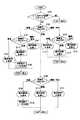
図16は、上記図15に示した構成により実施されるディジタルカメラ200a及び200bの動作を示したものである。
【0065】
先ず、接続検出部221は、他のディジタルカメラがUSBコネクタ204を介して接続されているか否か判別する(ステップS701)。この判別結果により、他のディジタルカメラが接続されていない場合、再度本ステップ処理を実行する。
【0066】
ステップS701での判別の結果、他のディジタルカメラが接続されている場合、モード情報取得部222は、自カメラの動作モード情報(以下、「接続元の動作モード」と言う)を取得すると共に、USBコネクタ204を介して接続されている他のディジタルカメラの動作モード情報(以下、「接続先の動作モード」と言う)を取得する。
そして、画面表示制御部223及び送受信部224は、モード情報取得部222にて得られた接続元及び接続先の動作モードに基づいて、次のようなステップS703〜S716の処理を実行する(ステップS702)。
【0067】
ステップS703〜S707:
接続元の動作モードが<受信モード>に設定されている場合、画面表示制御部223及び送受信部224は、接続先の動作モードに基づいて、次のようなステップS704〜S707の処理を実行する(ステップS703)。
【0068】
ステップS704:
接続先の動作モードが<受信モード>に設定されていた場合、画面表示制御部223は、このときのディジタルカメラ200a及び200bの操作の説明の画面を、液晶モニタ203に表示させる。液晶モニタ203に表示する画面情報としては、例えば、メモリ225に予め用意されている、図17(a)に示すような操作画面情報を用いる。したがって、この場合には、上記図17(a)の画面が液晶モニタ203に表示されることになる。その後、ステップS701へ戻り、以降の処理ステップを繰り返し実行する。
【0069】
ステップS705、ステップS706:
接続先の動作モードが<送信モード>に設定されていた場合、画面表示制御部223は、このときのディジタルカメラ200a及び200bの操作の説明の画面を、液晶モニタ203に表示させる。液晶モニタ203に表示する画面情報としては、例えば、メモリ225に予め用意されている、上記図17(b)に示すような操作画面情報を用いる。したがって、この場合には、上記図17(b)の画面が液晶モニタ203に表示されることになる(ステップS705)。そして、送受信部224は、接続先のディジタルカメラから送信されてきたデータを受信して、これをメモリ212へ記録する(ステップS706)。全てのデータ受信及び記録終了後、ステップS701へ戻り、以降の処理ステップを繰り返し実行する。
【0070】
ステップS707:
接続先の動作モードが<撮影モード>又は<再生モード>に設定されていた場合、画面表示制御部223は、このときのディジタルカメラ200a及び200bの操作の説明の画面を、液晶モニタ203に表示させる。液晶モニタ203に表示する画面情報としては、例えば、メモリ225に予め用意されている、上記図17(c)に示すような操作画面情報を用いる。したがって、この場合には、上記図17(c)の画面が液晶モニタ203に表示されることになる。その後、ステップS701へ戻り、以降の処理ステップを繰り返し実行する。
【0071】
ステップS708〜S712:
接続元の動作モードが<送信モード>に設定されている場合、画面表示制御部223及び送受信部224は、接続先の動作モードに基づいて、次のようなステップS709〜S712の処理を実行する(ステップS708)。
【0072】
ステップS709、ステップS710:
接続先の動作モードが<受信モード>に設定されていた場合、画面表示制御部223は、このときのディジタルカメラ200a及び200bの操作の説明の画面を、液晶モニタ203に表示させる。液晶モニタ203に表示する画面情報としては、例えば、メモリ225に予め用意されている、上記図17(d)に示すような操作画面情報を用いる。したがって、この場合には、上記図17(d)の画面が液晶モニタ203に表示されることになる(ステップS709)。そして、送受信部224は、接続先のディジタルカメラに対して、メモリ212内のデータを送信する(ステップS710)。全てのデータ送信録終了後、ステップS701へ戻り、以降の処理ステップを繰り返し実行する
【0073】
ステップS711:
接続先の動作モードが<送信モード>に設定されていた場合、画面表示制御部223は、このときのディジタルカメラ200a及び200bの操作の説明の画面を、液晶モニタ203に表示させる。液晶モニタ203に表示する画面情報としては、例えば、メモリ225に予め用意されている、上記図17(e)に示すような操作画面情報を用いる。したがって、この場合には、上記図17(e)の画面が液晶モニタ203に表示されることになる。その後、ステップS701へ戻り、以降の処理ステップを繰り返し実行する。
【0074】
ステップS712:
接続先の動作モードが<撮影モード>又は<再生モード>に設定されていた場合、画面表示制御部223は、このときのディジタルカメラ200a及び200bの操作の説明の画面を、液晶モニタ203に表示させる。液晶モニタ203に表示する画面情報としては、例えば、メモリ225に予め用意されている、上記図17(f)に示すような操作画面情報を用いる。したがって、この場合には、上記図17(f)の画面が液晶モニタ203に表示されることになる。その後、ステップS701へ戻り、以降の処理ステップを繰り返し実行する。
【0075】
ステップS713〜S716:
接続元の動作モードが<撮影モード>又は<再生モード>に設定されている場合、画面表示制御部223及び送受信部224は、接続先の動作モードに基づいて、次のようなステップS714〜S716の処理を実行する(ステップS713)。
【0076】
ステップS714:
接続先の動作モードが<受信モード>に設定されていた場合、画面表示制御部223は、このときのディジタルカメラ200a及び200bの操作の説明の画面を、液晶モニタ203に表示させる。液晶モニタ203に表示する画面情報としては、例えば、メモリ225に予め用意されている、図18(g)に示すような操作画面情報を用いる。したがって、この場合には、上記図18(g)の画面が液晶モニタ203に表示されることになる。その後、ステップS701へ戻り、以降の処理ステップを繰り返し実行する。
【0077】
ステップS715:
接続先の動作モードが<送信モード>に設定されていた場合、画面表示制御部223は、このときのディジタルカメラ200a及び200bの操作の説明の画面を、液晶モニタ203に表示させる。液晶モニタ203に表示する画面情報としては、例えば、メモリ225に予め用意されている、上記図18(h)に示すような操作画面情報を用いる。したがって、この場合には、上記図18(h)の画面が液晶モニタ203に表示されることになる。その後、ステップS701へ戻り、以降の処理ステップを繰り返し実行する。
【0078】
ステップS716:
接続先の動作モードが<撮影モード>又は<再生モード>に設定されていた場合、画面表示制御部223は、このときのディジタルカメラ200a及び200bの操作の説明の画面を、液晶モニタ203に表示させる。液晶モニタ203に表示する画面情報としては、例えば、メモリ225に予め用意されている、上記図18(i)に示すような操作画面情報を用いる。したがって、この場合には、上記図18(i)の画面が液晶モニタ203に表示されることになる。その後、ステップS701へ戻り、以降の処理ステップを繰り返し実行する。
【0079】
上述のような処理がディジタルカメラ200aとディジタルカメラ200bのそれぞれで実行されることにより、例えば、ディジタルカメラ200aが<送信モード>に設定され、ディジタルカメラ200bが<撮影モード>に設定され、ディジタルカメラ200aとディジタルカメラ200bがUSBケーブル400によって接続されている場合、ディジタルカメラ200aの液晶モニタには、上記図17(f)に示したような操作説明画面が表示され、他方のディジタルカメラ200bの液晶モニタには、上記図18(h)に示したような操作説明画面が表示されることになる。また、例えば、ディジタルカメラ200aとディジタルカメラ200bの両方が<受信モード>に設定されている場合、双方の液晶モニタにはそれぞれ、上記図17(a)に示したような操作説明画面が表示されることになる。
【0080】
上述のように、本実施の形態では、ディジタルカメラが、自カメラの動作モードと共に、USBケーブル400により接続されている他のディジタルカメラの動作モードを検出し、それらの動作モードに基づいて、互いのディジタルカメラでの操作方法を表示するように構成したので、利用者は、他のディジタルカメラを自カメラにUSBケーブル400で接続した時点で、双方のディジタルカメラの操作を、簡単且つ的確に把握することができ、適切な操作を行うことができる。これにより、利用者の負担を軽減することができる。
【0081】
尚、上述した実施の形態において、ディジタルカメラ200a及び200bは、同一種類のものに限らず、互いに通信可能であり、同様の動作を行うように設計されたものであればよい。
【0082】
(第4の実施の形態)
上述した第1の実施の形態では、コンピュータ装置300にディジタルカメラ200が接続されたとき、コンピュータ300のCRTモニタ301に上記図13(a)〜(d)に示したような、ディジタルカメラ200の操作方法の画面を表示するようにした。
これに対して本実施の形態では、コンピュータ装置300にディジタルカメラ200が接続されたとき、コンピュータ装置300のCRTモニタ301に、例えば、図19に示すような画面を表示し、さらに、この画面上からの操作及びディジタルカメラ200の動作モードに従った動作を行う。
【0083】
このため、ここでのコンピュータ装置300は、例えば、図20に示すように、USBコネクタ303の先にデジタルカメラ200が接続されたことを検出する接続検出部331と、接続検出部331の検出結果に基づいて上記図19の画面をCRTモニタ301に表示させる画面表示制御部332と、画面表示制御部332による表示画面上の操作に基づいてディジタルカメラ200での動作モードの設定情報を取得するモード情報取得部333と、画面表示制御部332による表示画面上の操作及び設定情報取得部333にて得られた設定情報に基づいて受信、送信、撮影、及び再生等のための動作制御を行う動作制御部334とを備えている。
これらの各構成部331〜334は、例えば、コンピュータ装置300内部のCPU(図示せず)により実現される。
【0084】
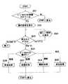
図21は、上記図20に示した構成により実施されるコンピュータ装置300の動作を示したものである。
【0085】
先ず、接続検出部331は、ディジタルカメラ200がUSBコネクタ303を介して接続されているか否か判別する(ステップS521)。この判別結果により、ディジタルカメラ200が接続されていない場合、再度本ステップ処理を実行する。
【0086】
ステップS521での判別の結果、ディジタルカメラ200が接続されている場合、画面表示制御部332は、上記図19に示したような画面を、CRTモニタ301に表示させる。この画面情報は、メモリ324に予め用意されている(ステップS522)。
【0087】
そこで、利用者は、CRTモニタ301に表示されている画面に従った操作を行う。
具体的には例えば、上記図19に示すように、このときCRTモニタ301に表示される画面は、操作方法の表示領域と共に、OKボタン801、キャンセルボタン802、及びヘルプボタン803が設けられた手順説明ウィンドウから構成される。したがって、利用者は、OKボタン801、キャンセルボタン802、及びヘルプボタン803の何れかの所望するボタンを、マウス305等を用いて押下する。この操作情報は、画面表示制御部332、モード情報取得部333、及び動作制御部334へ与えられる。
画面表示制御部332、モード情報取得部333、及び動作制御部334は、上記図19の画面上からの操作に基づいて、次のようなステップ523〜S529の処理を実行する。
【0088】
ステップS523、ステップS524:
画面表示制御部332は、上記図19の画面上で操作されたボタンがヘルプボタン803であった場合(ステップS523)、さらに詳細な操作方法をCRTモニタ301に表示させる(ステップS524)。このときCRTモニタ301に表示する画面情報としては、例えば、メモリ335に予め用意されている操作画面情報を用いる。その後、ステップS523へ戻り、以降の処理ステップを繰り返し実行する。
一方、上記図19の画面上でキャンセルボタン802が押下された場合には、本処理終了となる。また、上記図19の画面上でOKボタン801が押下された場合には、次のステップS525からの処理へと進む。
【0089】
ステップS525〜S529:
上記図19の画面上でOKボタン801が押下された場合、モード情報取得部333は、ディジタルカメラ200の動作モード情報(動作モードの設定値)を取得する。
そして、動作制御部334は、モード情報取得部322にて得られたモード情報に基づいて(ステップS525)、ステップS526〜S529の処理を実行する。すなわち、動作制御部334は、ディジタルカメラ200の動作モードが<受信モード>に設定されていた場合には受信処理のための動作制御を行い(ステップS526)、<送信モード>に設定されていた場合には送信処理のための動作制御を行い(ステップS527)、<撮影モード>に設定されていた場合には撮影処理のための動作制御を行い(ステップS528)、<再生モード>に設定されていた場合には再生処理のための動作制御を行う(ステップS529)。
【0090】
上述のような構成によっても、第1及び第2の実施の形態での効果と同様に、利用者は、ディジタルカメラ200をコンピュータ装置300に接続した時点で、ディジタルカメラ200の操作を簡単且つ的確に把握することができ、適切な操作を行うことができる。これにより、利用者の負担を軽減することができる。
【0091】
尚、上述した第4の実施の形態でのステップS526〜S529において、上述した第2の実施の形態と同様の、ディジタルカメラ200の動作モードに対応した操作方法の画面(上記図13(a)〜(d)参照)をCRTモニタ301に表示する処理を加えるようにしてもよい。
また、上述した第4の実施の形態は、上述した第3の実施の形態での構成(ディジタルカメラ200の機能とコンピュータ装置300の機能とを併せ持つディジタルカメラ200a及び200bを接続する構成)にも適用可能である。
【0092】
また、本発明の目的は、上述した各実施の形態のホスト及び端末の機能を実現するソフトウェアのプログラムコードを記憶した記憶媒体を、システム或いは装置に供給し、そのシステム或いは装置のコンピュータ(又はCPUやMPU)が記憶媒体に格納されたプログラムコードを読みだして実行することによっても、達成されることは言うまでもない。 この場合、記憶媒体から読み出されたプログラムコード自体が各実施の形態の機能を実現することとなり、そのプログラムコードを記憶した記憶媒体は本発明を構成することとなる。
プログラムコードを供給するための記憶媒体としては、ROM、フロッピーディスク、ハードディスク、光ディスク、光磁気ディスク、CD−ROM、CD−R、磁気テープ、不揮発性のメモリカード等を用いることができる。
また、コンピュータが読みだしたプログラムコードを実行することにより、各実施の形態の機能が実現されるだけでなく、そのプログラムコードの指示に基づき、コンピュータ上で稼動しているOS等が実際の処理の一部又は全部を行い、その処理によって各実施の形態の機能が実現される場合も含まれることは言うまでもない。
さらに、記憶媒体から読み出されたプログラムコードが、コンピュータに挿入された拡張機能ボードやコンピュータに接続された機能拡張ユニットに備わるメモリに書き込まれた後、そのプログラムコードの指示に基づき、その機能拡張ボードや機能拡張ユニットに備わるCPUなどが実際の処理の一部又は全部を行い、その処理によって各実施の形態の機能が実現される場合も含まれることは言うまでもない。
【0093】
【発明の効果】
以上説明したように本発明によれば、情報処理装置に外部機器が接続されると、情報処理装置の表示言語の設定が外部機器の表示言語の設定に応じて自動的に変更される。そのため利用者は、情報処理装置で表示言語の設定をするための操作を行うことなく、情報処理装置に外部機器を接続させるだけで情報処理装置の表示言語の設定を変更することができる。
【図面の簡単な説明】
【図1】第1の実施の形態において、本発明を適用したデータ通信システムの構成を説明するための図である。
【図2】上記データ通信システムのディジタルカメラの構成を説明するための図である。
【図3】上記ディジタルカメラでの表示言語の設定を説明するための図である。
【図4】上記表示言語の設定により英語設定がなされた場合の表示状態を説明するための図である。
【図5】上記データ通信システムのコンピュータ装置の構成を説明するための図である。
【図6】上記コンピュータ装置において、画像取込ソフトウェアが起動されたときの表示画面を説明するための図である。
【図7】上記コンピュータ装置において、表示言語の設定で英語設定がなされた場合の上記表示画面の状態を説明するための図である。
【図8】上記コンピュータ装置内部の構成を示すブロック図である。
【図9】上記コンピュータ装置内部の動作を説明するためのフローチャートである。
【図10】第2の実施の形態における上記ディジタルカメラの構成を説明するための図である。
【図11】第2の実施の形態における上記コンピュータ装置内部の構成を示すブロック図である。
【図12】上記コンピュータ装置で表示される画面を説明するための図である。
【図13】上記コンピュータ装置の動作を説明するためのフローチャートである。
【図14】第3の実施の形態において、本発明を適用したデータ通信システムの構成を説明するための図である。
【図15】上記データ通信システムのディジタルカメラ内部の構成を示すブロック図である。
【図16】上記ディジタルカメラの動作を説明するためのフローチャートである。
【図17】上記ディジタルカメラで表示される画面(a〜f)を説明するための図である。
【図18】上記ディジタルカメラで表示される画面(g〜i)を説明するための図である。
【図19】第4の実施の形態における上記コンピュータ装置で表示される画面を説明するための図である。
【図20】上記コンピュータ装置内部の構成を示すブロック図である。
【図21】上記コンピュータ装置の動作を説明するためのフローチャートである。
【符号の説明】
100 データ通信システム
200 ディジタルカメラ
204 USBコネクタ
300 コンピュータ装置
301 CRTモニタ
303 USBコネクタ
311 接続検出部
312 設定情報取得部
313 設定変更部
321 画像取込ソフトウェア
400 USBケーブル[0001]
BACKGROUND OF THE INVENTION
The present invention provides, for example, data communication between a terminal device such as a digital camera or a personal digital assistant device (PDA: Personal Digital Assistants, hereinafter also referred to as “portable terminal device”) and a computer device such as a personal computer. The present invention relates to a technique for displaying information.
[0002]
[Prior art]
Conventionally, for example, a terminal device such as a digital camera or PDA (portable terminal device) that is used to input and display data such as images and characters is connected to a computer device that is used to record and display data. There are systems that can transfer data from a terminal device to a computer device or from a computer device to a terminal device.
[0003]
Here, the above-described terminal device, for example, a digital camera currently on the market, is generally equipped with a serial communication port of the RS-232C standard. As a result, the serial communication port of the digital camera can be directly connected to the serial communication port of the computer device, whereby mutual data transfer can be performed.
As a connection means between such a terminal device and a computer device, parallel communication or infrared communication is generally used in addition to the serial communication described above.
[0004]
In addition, as the above-described terminal device, there is a terminal device capable of switching operation modes such as data input, data transfer, and list display by means of a physical switch or a menu displayed on a display unit. .
[0005]
Specifically, for example, there is a digital camera provided with a switch between a photographing mode and a communication mode. This digital camera is mainly configured as follows.
In the shooting mode, data is input (that is, shooting operation for obtaining an image) by pressing the release button, but at this time, no data is transferred to or from the computer device. On the other hand, in the communication mode, data is transferred to and from the computer device, but no photographing operation is performed at this time.
・ In accordance with the operation mode switching, the release button is disabled in the communication mode. Thereby, an erroneous operation can be prevented.
A function of one operation switch is switched according to the switching of the operation mode so that one operation switch has a plurality of functions. Thereby, the total number of operation switches can be reduced.
[0006]
There is also a digital camera configured as follows.
・ Display the menu on the LCD screen as the display unit, and set all the languages used for displaying menus and information on the LCD screen according to the display language (Japanese, English, etc.) setting from the menu Switch to the selected language. Thereby, one digital camera can be used in various regions.
[0007]
On the other hand, some computer devices and application software used in the computer devices can change the data display method by changing settings.
For example, “Windows” of Microsoft Corporation in the United States has a function for setting a display language (Japanese, English, etc.). When the display language is changed by this function, it is used in a user interface of application software that operates on Windows. Language is changed.
[0008]
Further, in the computer device, when the terminal device as described above is connected to this device, this connection is detected, the state of the connected terminal device is also detected, and when the state of the terminal device changes, There is a computer device having a function capable of detecting a change in the state.
For example, in the case where a personal computer equipped with USB (Universal Serial Bus) (hereinafter simply referred to as “PC” or “personal computer”) equipped with “Windows 98” of Microsoft Corporation in the United States, the state of the device connected to the USB Has been made to be able to detect.
[0009]
[Problems to be solved by the invention]
However, in the conventional computer apparatus as described above, in particular, in the conventional computer apparatus in which the data display method can be changed by changing the system setting, when there are a plurality of users, each user has his / her own request. If the display is to be performed with the setting to be performed, each user needs an operation for switching the setting of the previous user to his own setting. This operation is also required when using a computer device that has never been used before.
In other words, conventionally, when a computer device is used for the first time, or when a plurality of users using different settings use one computer device alternately, the setting of the computer device is changed every time. There was a need.
[0011]
Therefore, an object of the present invention is to enable a user to change the display language setting of the information processing apparatus without performing an operation of changing the display language setting in the information processing apparatus.
[0012]
[Means for Solving the Problems]
An information processing apparatus according to the present invention is an information processing apparatus that is communicably connected to an external device, wherein the external device is connected by a connection detection unit that detects that the external device is connected, and the connection detection unit When it is detected that the setting is detected by a setting detection unit that automatically detects a setting of a display language that can be set in the information processing apparatus among the settings in the external device, and when the setting is detected by the setting detection unit, It further comprises setting change means for automatically changing the display language setting given in advance to the information processing apparatus in accordance with the display language setting detected by the setting detection means.
The information processing system of the present invention is an information processing system in which a plurality of devices are communicably connected, and at least one of the plurality of devices has the function of the information processing apparatus of the present invention. Features.
An operation control method for an information processing apparatus according to the present invention is an operation control method for an information processing apparatus that is communicably connected to an external device, the connection detecting step for detecting that the external device is connected, and the connection When the detection step detects that the external device is connected, a setting detection step for automatically detecting a display language setting that can be set in the information processing apparatus among the settings in the external device, and the setting detection step When the setting is detected, the setting of the display language previously given to the information processing apparatus is detected.Step And a setting change step for automatically changing the display language according to the setting of the display language.
The computer-readable recording medium of the present invention is communicably connected to an external device.Information processing device Can be set in the information processing apparatus among the settings in the external device when the connection detection unit detects that the external device is connected and the connection detection unit detects that the external device is connected. A setting detection unit for automatically detecting a setting of a display language; and when the setting is detected by the setting detection unit, a setting of the display language previously given to the information processing apparatus is detected by the setting detection unit. According to another aspect of the present invention, there is recorded a program for functioning as a setting changing unit that automatically changes according to the setting of the display language.
[0035]
DETAILED DESCRIPTION OF THE INVENTION
Hereinafter, embodiments of the present invention will be described with reference to the drawings.
[0036]
(First embodiment)
The present invention is applied to, for example, a
In this
The
The
Hereinafter, the
[0037]
[Configuration of Digital Camera 200]
FIGS. 2A and 2B show the configuration of the
[0038]
First, as shown in FIG. 2A, an
The
On the other hand, as shown in FIG. 2B, a liquid crystal monitor 203 as a data display means, a
A
[0039]
In the
FIGS. 3A and 3B show an example of a menu screen for setting the display language at this time.
When the item “Language” is selected on the menu screen shown in FIG. 3A, the screen shifts to a screen for setting the display language as shown in FIG. On this screen, you can select the desired language (here “Japanese”) from various languages such as “English”, “Deutsch”, “Fran? Ais”, “Japanese”. .
With this display language setting, for example, when “English” is selected and set, the subsequent display on the
[0040]
[Configuration of Computer Device 300]
[0041]
For example, as shown in FIG. 5, the
[0042]
Further, in the
In such image capturing software, the display language can be switched by setting.
[0043]
FIG. 6 shows an example of a screen displayed on the CRT monitor 301 by the image capturing software. The screen of FIG. 6 shows a state when the display language is set to Japanese. If this display language is set to English, for example, the screen state of English display as shown in FIG. 7 is obtained.
[0044]
Here, the
Therefore, for example, as illustrated in FIG. 8, the
Each of these
[0045]
FIG. 9 shows the operation of the
[0046]
First, the
[0047]
If the result of determination in step S501 is that the
[0048]
Then, the setting
Thereby, for example, when the display language on the
[0049]
As described above, in this embodiment, the
[0050]
In the above-described embodiment, for the sake of simplicity of explanation, the setting of the display language in the
[0051]
(Second Embodiment)
In the present embodiment, in the
[0052]
In this
Then, the
[0053]
Further, for example, as illustrated in FIG. 11, the
Each of these
[0054]
FIG. 12 shows the operation of the
[0055]
First, the
[0056]
If the result of determination in step S511 is that the
And the screen
[0057]
Step S513:
When the operation mode of the
Thereafter, the process returns to step S511, and the subsequent processing steps are repeatedly executed.
[0058]
Step S514:
When the operation mode of the
[0059]
Step S515:
When the operation mode of the
[0060]
Step S516:
When the operation mode of the
[0061]
As described above, in the present embodiment, the
[0062]
(Third embodiment)
The present invention is applied to, for example, a
The
[0063]
Here, the
For this reason, each of the
Each of these
[0064]
FIG. 16 shows the operations of the
[0065]
First, the
[0066]
As a result of the determination in step S701, when another digital camera is connected, the mode
Then, the screen
[0067]
Steps S703 to S707:
When the operation mode of the connection source is set to <reception mode>, the screen
[0068]
Step S704:
When the operation mode of the connection destination is set to <reception mode>, the screen
[0069]
Step S705, Step S706:
When the operation mode of the connection destination is set to <transmission mode>, the screen
[0070]
Step S707:
When the operation mode of the connection destination is set to <shooting mode> or <playback mode>, the screen
[0071]
Steps S708 to S712:
When the operation mode of the connection source is set to <transmission mode>, the screen
[0072]
Step S709, Step S710:
When the operation mode of the connection destination is set to <reception mode>, the screen
[0073]
Step S711:
When the operation mode of the connection destination is set to <transmission mode>, the screen
[0074]
Step S712:
When the operation mode of the connection destination is set to <shooting mode> or <playback mode>, the screen
[0075]
Steps S713 to S716:
When the operation mode of the connection source is set to <shooting mode> or <playback mode>, the screen
[0076]
Step S714:
When the operation mode of the connection destination is set to <reception mode>, the screen
[0077]
Step S715:
When the operation mode of the connection destination is set to <transmission mode>, the screen
[0078]
Step S716:
When the operation mode of the connection destination is set to <shooting mode> or <playback mode>, the screen
[0079]
By executing the processing as described above in each of the
[0080]
As described above, in this embodiment, the digital camera detects the operation mode of another digital camera connected by the
[0081]
In the above-described embodiment, the
[0082]
(Fourth embodiment)
In the first embodiment described above, when the
On the other hand, in the present embodiment, when the
[0083]
Therefore, for example, as illustrated in FIG. 20, the
Each of these
[0084]
FIG. 21 shows the operation of the
[0085]
First, the
[0086]
If the result of determination in step S521 is that the
[0087]
Therefore, the user performs an operation according to the screen displayed on the
Specifically, for example, as shown in FIG. 19, the screen displayed on the CRT monitor 301 at this time is a procedure in which an
The screen
[0088]
Step S523, Step S524:
When the button operated on the screen of FIG. 19 is the help button 803 (step S523), the screen
On the other hand, when the cancel
[0089]
Steps S525-S529:
When the
Then, based on the mode information obtained by the mode information acquisition unit 322 (Step S525), the
[0090]
Even with the above-described configuration, similarly to the effects in the first and second embodiments, the user can easily and accurately operate the
[0091]
In steps S526 to S529 in the above-described fourth embodiment, the operation method screen corresponding to the operation mode of the
The fourth embodiment described above is also applied to the configuration of the third embodiment described above (a configuration in which
[0092]
Another object of the present invention is to supply a storage medium storing software program codes for realizing the functions of the host and terminal of each of the above-described embodiments to a system or apparatus, and the computer (or CPU) of the system or apparatus. Needless to say, this can also be achieved by reading and executing the program code stored in the storage medium. In this case, the program code itself read from the storage medium implements the functions of the respective embodiments, and the storage medium storing the program code constitutes the present invention.
As a storage medium for supplying the program code, a ROM, a floppy disk, a hard disk, an optical disk, a magneto-optical disk, a CD-ROM, a CD-R, a magnetic tape, a nonvolatile memory card, or the like can be used.
Further, by executing the program code read by the computer, not only the functions of the respective embodiments are realized, but also the OS or the like running on the computer based on the instruction of the program code performs the actual processing. It goes without saying that a case where the functions of the respective embodiments are realized by performing part or all of the above and the processing thereof is included.
Further, after the program code read from the storage medium is written to the memory provided in the extension function board inserted in the computer or the function extension unit connected to the computer, the function extension is performed based on the instruction of the program code. It goes without saying that the case where the CPU or the like provided in the board or function expansion unit performs part or all of the actual processing and the functions of the respective embodiments are realized by the processing.
[0093]
【The invention's effect】
As described above, according to the present invention, when an external device is connected to the information processing device, the display language setting of the information processing device is automatically changed according to the display language setting of the external device. Therefore, the user can change the setting of the display language of the information processing apparatus by simply connecting an external device to the information processing apparatus without performing an operation for setting the display language on the information processing apparatus.
[Brief description of the drawings]
FIG. 1 is a diagram for explaining a configuration of a data communication system to which the present invention is applied in a first embodiment.
FIG. 2 is a diagram for explaining a configuration of a digital camera of the data communication system.
FIG. 3 is a diagram for explaining setting of a display language in the digital camera.
FIG. 4 is a diagram for explaining a display state when English is set by setting the display language.
FIG. 5 is a diagram for explaining a configuration of a computer device of the data communication system.
FIG. 6 is a diagram for explaining a display screen when image capturing software is activated in the computer device.
FIG. 7 is a diagram for explaining a state of the display screen when English is set as a display language in the computer device.
FIG. 8 is a block diagram showing an internal configuration of the computer apparatus.
FIG. 9 is a flowchart for explaining the internal operation of the computer apparatus.
FIG. 10 is a diagram for explaining a configuration of the digital camera according to a second embodiment.
FIG. 11 is a block diagram showing an internal configuration of the computer device according to a second embodiment.
FIG. 12 is a diagram for explaining a screen displayed on the computer device.
FIG. 13 is a flowchart for explaining the operation of the computer apparatus.
FIG. 14 is a diagram for explaining a configuration of a data communication system to which the present invention is applied in the third embodiment;
FIG. 15 is a block diagram showing an internal configuration of a digital camera of the data communication system.
FIG. 16 is a flowchart for explaining the operation of the digital camera.
FIG. 17 is a diagram for explaining screens (af) displayed on the digital camera.
FIG. 18 is a diagram for explaining screens (gi) displayed on the digital camera.
FIG. 19 is a diagram for explaining a screen displayed on the computer device according to the fourth embodiment;
FIG. 20 is a block diagram showing an internal configuration of the computer apparatus.
FIG. 21 is a flowchart for explaining the operation of the computer apparatus.
[Explanation of symbols]
100 Data communication system
200 Digital camera
204 USB connector
300 Computer device
301 CRT monitor
303 USB connector
311 Connection detector
312 Setting information acquisition unit
313 Setting change section
321 Image capture software
400 USB cable
Claims (8)
Translated fromJapanese前記外部機器が接続されたことを検出する接続検出手段と、
前記接続検出手段によって前記外部機器が接続されたと検出されると、前記外部機器における設定のうち前記情報処理装置に設定可能な表示言語の設定を自動的に検出する設定検出手段と、
前記設定検出手段によって前記設定が検出されると、前記情報処理装置に予め与えられていた表示言語の設定を前記設定検出手段によって検出された表示言語の設定に応じて自動的に変更する設定変更手段とを有することを特徴とする情報処理装置。An information processing apparatus that is communicably connected to an external device,
Connection detecting means for detecting that the external device is connected;
A setting detection unit that automatically detects a display language setting that can be set in the information processing device among the settings in the external device when the connection detection unit detects that the external device is connected;
When the setting is detected by the setting detection means, a setting change is automatically made to change the display language setting given in advance to the information processing apparatus according to the display language setting detected by the setting detection means. And an information processing apparatus.
前記複数の機器のうち少なくとも1つの機器は、請求項1〜3の何れか1項に記載の情報処理装置の機能を有することを特徴とする情報処理システム。An information processing system in which a plurality of devices are communicably connected,
The information processing system according to claim 1, wherein at least one of the plurality of devices has the function of the information processing apparatus according to claim 1.
前記外部機器が接続されたことを検出する接続検出ステップと、
前記接続検出ステップによって前記外部機器が接続されたと検出されると、前記外部機器における設定のうち前記情報処理装置に設定可能な表示言語の設定を自動的に検出する設定検出ステップと、
前記設定検出ステップによって前記設定が検出されると、前記情報処理装置に予め与えられていた表示言語の設定を前記設定検出ステップによって検出された表示言語の設定に応じて自動的に変更する設定変更ステップとを有することを特徴とする情報処理装置の動作制御方法。An operation control method for an information processing apparatus that is communicably connected to an external device,
A connection detection step of detecting that the external device is connected;
A setting detection step for automatically detecting a setting of a display language that can be set in the information processing apparatus among the settings in the external device when it is detected that the external device is connected by the connection detection step;
When the setting is detected by the setting detectionstep , a setting change that automatically changes the display language setting previously given to the information processing apparatus according to the display language setting detected by the setting detectionstep And a step of controlling the operation of the information processing apparatus.
前記外部機器が接続されたことを検出する接続検出手段と、
前記接続検出手段によって前記外部機器が接続されたと検出されると、前記外部機器における設定のうち前記情報処理装置に設定可能な表示言語の設定を自動的に検出する設定検出手段と、
前記設定検出手段によって前記設定が検出されると、前記情報処理装置に予め与えられていた表示言語の設定を前記設定検出手段によって検出された表示言語の設定に応じて自動的に変更する設定変更手段として機能させるためのプログラムを記録したことを特徴とするコンピュータ読み取り可能な記録媒体。Aninformation processing device that is communicably connected to an external device.
Connection detecting means for detecting that the external device is connected;
A setting detection unit that automatically detects a display language setting that can be set in the information processing device among the settings in the external device when the connection detection unit detects that the external device is connected;
When the setting is detected by the setting detection means, a setting change is automatically made to change the display language setting given in advance to the information processing apparatus according to the display language setting detected by the setting detection means. A computer-readable recording medium in which a program for functioning as a means is recorded.
Priority Applications (3)
| Application Number | Priority Date | Filing Date | Title |
|---|---|---|---|
| JP14072999AJP4557331B2 (en) | 1999-05-20 | 1999-05-20 | Information processing apparatus, information processing system, operation control method, and computer-readable recording medium |
| US09/572,586US7535491B1 (en) | 1999-05-20 | 2000-05-17 | Detecting and using mode/setting information |
| US11/855,454US7528861B2 (en) | 1999-05-20 | 2007-09-14 | Changing a display language for software based on a detected display language of a connected device |
Applications Claiming Priority (1)
| Application Number | Priority Date | Filing Date | Title |
|---|---|---|---|
| JP14072999AJP4557331B2 (en) | 1999-05-20 | 1999-05-20 | Information processing apparatus, information processing system, operation control method, and computer-readable recording medium |
Related Child Applications (1)
| Application Number | Title | Priority Date | Filing Date |
|---|---|---|---|
| JP2006288109ADivisionJP4273148B2 (en) | 2006-10-23 | 2006-10-23 | Information processing system, information processing method, and computer-readable recording medium |
Publications (2)
| Publication Number | Publication Date |
|---|---|
| JP2000330918A JP2000330918A (en) | 2000-11-30 |
| JP4557331B2true JP4557331B2 (en) | 2010-10-06 |
Family
ID=15275362
Family Applications (1)
| Application Number | Title | Priority Date | Filing Date |
|---|---|---|---|
| JP14072999AExpired - Fee RelatedJP4557331B2 (en) | 1999-05-20 | 1999-05-20 | Information processing apparatus, information processing system, operation control method, and computer-readable recording medium |
Country Status (2)
| Country | Link |
|---|---|
| US (2) | US7535491B1 (en) |
| JP (1) | JP4557331B2 (en) |
Families Citing this family (50)
| Publication number | Priority date | Publication date | Assignee | Title |
|---|---|---|---|---|
| EP1229720A3 (en)* | 2001-01-31 | 2004-04-14 | Fuji Photo Film Co., Ltd. | Digital camera and method of controlling same |
| US20030107654A1 (en) | 2001-12-12 | 2003-06-12 | Nikon Corporation | Digital camera |
| US8189059B2 (en)* | 2003-01-29 | 2012-05-29 | Nikon Corporation | Digital camera and digital camera system |
| US7876357B2 (en) | 2005-01-31 | 2011-01-25 | The Invention Science Fund I, Llc | Estimating shared image device operational capabilities or resources |
| US20060174203A1 (en) | 2005-01-31 | 2006-08-03 | Searete Llc, A Limited Liability Corporation Of The State Of Delaware | Viewfinder for shared image device |
| US9082456B2 (en) | 2005-01-31 | 2015-07-14 | The Invention Science Fund I Llc | Shared image device designation |
| US9325781B2 (en) | 2005-01-31 | 2016-04-26 | Invention Science Fund I, Llc | Audio sharing |
| US20060170956A1 (en)* | 2005-01-31 | 2006-08-03 | Jung Edward K | Shared image devices |
| US7920169B2 (en) | 2005-01-31 | 2011-04-05 | Invention Science Fund I, Llc | Proximity of shared image devices |
| US9124729B2 (en) | 2005-01-31 | 2015-09-01 | The Invention Science Fund I, Llc | Shared image device synchronization or designation |
| US8606383B2 (en)* | 2005-01-31 | 2013-12-10 | The Invention Science Fund I, Llc | Audio sharing |
| US9910341B2 (en) | 2005-01-31 | 2018-03-06 | The Invention Science Fund I, Llc | Shared image device designation |
| US8902320B2 (en) | 2005-01-31 | 2014-12-02 | The Invention Science Fund I, Llc | Shared image device synchronization or designation |
| US9489717B2 (en) | 2005-01-31 | 2016-11-08 | Invention Science Fund I, Llc | Shared image device |
| US20070222865A1 (en) | 2006-03-15 | 2007-09-27 | Searete Llc, A Limited Liability Corporation Of The State Of Delaware | Enhanced video/still image correlation |
| US7872675B2 (en)* | 2005-06-02 | 2011-01-18 | The Invention Science Fund I, Llc | Saved-image management |
| US9451200B2 (en) | 2005-06-02 | 2016-09-20 | Invention Science Fund I, Llc | Storage access technique for captured data |
| US9621749B2 (en)* | 2005-06-02 | 2017-04-11 | Invention Science Fund I, Llc | Capturing selected image objects |
| US8072501B2 (en)* | 2005-10-31 | 2011-12-06 | The Invention Science Fund I, Llc | Preservation and/or degradation of a video/audio data stream |
| US9819490B2 (en) | 2005-05-04 | 2017-11-14 | Invention Science Fund I, Llc | Regional proximity for shared image device(s) |
| US9191611B2 (en) | 2005-06-02 | 2015-11-17 | Invention Science Fund I, Llc | Conditional alteration of a saved image |
| US9167195B2 (en)* | 2005-10-31 | 2015-10-20 | Invention Science Fund I, Llc | Preservation/degradation of video/audio aspects of a data stream |
| US8253821B2 (en)* | 2005-10-31 | 2012-08-28 | The Invention Science Fund I, Llc | Degradation/preservation management of captured data |
| US9967424B2 (en) | 2005-06-02 | 2018-05-08 | Invention Science Fund I, Llc | Data storage usage protocol |
| US9001215B2 (en) | 2005-06-02 | 2015-04-07 | The Invention Science Fund I, Llc | Estimating shared image device operational capabilities or resources |
| US8964054B2 (en) | 2006-08-18 | 2015-02-24 | The Invention Science Fund I, Llc | Capturing selected image objects |
| US8681225B2 (en) | 2005-06-02 | 2014-03-25 | Royce A. Levien | Storage access technique for captured data |
| US9942511B2 (en) | 2005-10-31 | 2018-04-10 | Invention Science Fund I, Llc | Preservation/degradation of video/audio aspects of a data stream |
| US10003762B2 (en) | 2005-04-26 | 2018-06-19 | Invention Science Fund I, Llc | Shared image devices |
| US7782365B2 (en)* | 2005-06-02 | 2010-08-24 | Searete Llc | Enhanced video/still image correlation |
| US8233042B2 (en)* | 2005-10-31 | 2012-07-31 | The Invention Science Fund I, Llc | Preservation and/or degradation of a video/audio data stream |
| US20070120980A1 (en)* | 2005-10-31 | 2007-05-31 | Searete Llc, A Limited Liability Corporation Of The State Of Delaware | Preservation/degradation of video/audio aspects of a data stream |
| JP4873533B2 (en) | 2005-12-15 | 2012-02-08 | 富士通株式会社 | High-speed serial transfer device test method, program and apparatus |
| JP4085120B2 (en) | 2006-02-10 | 2008-05-14 | 富士通株式会社 | Information display system, information display method and program |
| JP2008102897A (en)* | 2006-09-20 | 2008-05-01 | Olympus Corp | Handling procedure instruction device and method of instructing handling procedure, and program and recording medium thereof |
| US8090885B2 (en)* | 2008-01-14 | 2012-01-03 | Microsoft Corporation | Automatically configuring computer devices wherein customization parameters of the computer devices are adjusted based on detected removable key-pad input devices |
| US20090319694A1 (en) | 2008-06-20 | 2009-12-24 | Microsoft Corporation | Association of an input and output of a peripheral device in a computing system |
| JP2012221057A (en)* | 2011-04-05 | 2012-11-12 | Sharp Corp | Electronic apparatus system and electronic apparatus |
| JP5868038B2 (en)* | 2011-06-28 | 2016-02-24 | キヤノン株式会社 | Imaging apparatus, control method therefor, program, and storage medium |
| JP5872850B2 (en)* | 2011-11-07 | 2016-03-01 | オリンパス株式会社 | Imaging main body, imaging device system, and program |
| JP5978615B2 (en) | 2011-12-16 | 2016-08-24 | 日本電気株式会社 | Setting system and method |
| JP6194632B2 (en)* | 2013-05-16 | 2017-09-13 | 株式会社リコー | Program, setting information utilization system, information processing apparatus |
| KR102215860B1 (en)* | 2013-09-12 | 2021-02-16 | 삼성전자 주식회사 | Electronic device and control method thereof |
| JP6365605B2 (en)* | 2016-07-27 | 2018-08-01 | 日本電気株式会社 | Inter-terminal communication system and method |
| JP2018061125A (en)* | 2016-10-05 | 2018-04-12 | 株式会社ケイティーエス | Language switching device for communication apparatus |
| JP6610720B2 (en)* | 2018-07-05 | 2019-11-27 | 日本電気株式会社 | Setting system and method |
| US11227197B2 (en) | 2018-08-02 | 2022-01-18 | International Business Machines Corporation | Semantic understanding of images based on vectorization |
| DE102018132965A1 (en)* | 2018-12-19 | 2020-06-25 | Arnold & Richter Cine Technik Gmbh & Co. Betriebs Kg | Image capture device |
| KR102598868B1 (en)* | 2019-02-01 | 2023-11-06 | 삼성전자주식회사 | Electronic apparatus and the control method thereof |
| US20220147368A1 (en)* | 2019-07-26 | 2022-05-12 | Hewlett-Packard Development Company, L.P. | Configuring localizations based on peripheral device localization settings |
Family Cites Families (38)
| Publication number | Priority date | Publication date | Assignee | Title |
|---|---|---|---|---|
| US5231501A (en)* | 1989-05-25 | 1993-07-27 | Asahi Kogaku Kogyo Kabushiki Kaisha | Still video apparatus |
| US5706411A (en)* | 1992-11-09 | 1998-01-06 | Microsoft Corporation | Printer status user interface and methods relating thereto |
| JP3163872B2 (en)* | 1993-10-21 | 2001-05-08 | 株式会社日立製作所 | Computer equipment and imaging device |
| US5745809A (en)* | 1993-12-16 | 1998-04-28 | Nikon Corporation | Camera with correspondingly shaped operation members and display areas |
| ZA965340B (en)* | 1995-06-30 | 1997-01-27 | Interdigital Tech Corp | Code division multiple access (cdma) communication system |
| JPH09128129A (en) | 1995-11-01 | 1997-05-16 | Casio Comput Co Ltd | Help message display device |
| JP3661175B2 (en) | 1995-11-28 | 2005-06-15 | ソニー株式会社 | Connection status display method |
| JPH09163060A (en) | 1995-12-06 | 1997-06-20 | Matsushita Graphic Commun Syst Inc | Facsimile equipment and using method therefor |
| FI100041B (en)* | 1995-12-29 | 1997-08-29 | Nokia Telecommunications Oy | Procedure for estimating signal and noise quality as well as receivers |
| WO1997030375A1 (en)* | 1996-02-13 | 1997-08-21 | Obsidian Imaging, Inc. | Method and apparatus for configuring a camera through external means |
| US6188431B1 (en) | 1996-02-17 | 2001-02-13 | Casio Computers Co., Ltd. | Electronic still camera and method for communication between electronic still cameras |
| JPH09284696A (en) | 1996-02-17 | 1997-10-31 | Casio Comput Co Ltd | Electronic still camera and communication method between electronic still cameras |
| US6256063B1 (en)* | 1996-10-02 | 2001-07-03 | Fuji Photo Film Co., Ltd. | Image signal processing unit and electronic still camera |
| US6115137A (en)* | 1996-12-06 | 2000-09-05 | Canon Kabushiki Kaisha | Image processing system, digital camera, and printing apparatus |
| US20020105582A1 (en)* | 1997-01-09 | 2002-08-08 | Osamu Ikeda | Electronic camera with self-explanation/diagnosis mode |
| US6867800B1 (en)* | 1997-02-21 | 2005-03-15 | Canon Kabushiki Kaisha | System having an information processing apparatus and a data input apparatus, and method for controlling the system |
| JPH10250047A (en) | 1997-03-12 | 1998-09-22 | Minolta Co Ltd | Image forming system |
| JP2937163B2 (en)* | 1997-04-11 | 1999-08-23 | 日本電気株式会社 | Mobile communication system |
| JP3426105B2 (en)* | 1997-04-25 | 2003-07-14 | 任天堂株式会社 | Video game system and storage medium for video game |
| JP3909394B2 (en) | 1997-06-30 | 2007-04-25 | 株式会社島津製作所 | Operation instruction display method and measuring apparatus using the same |
| JP4054451B2 (en)* | 1997-08-26 | 2008-02-27 | キヤノン株式会社 | Communication device |
| US6259469B1 (en)* | 1997-09-05 | 2001-07-10 | Nikon Corporation | Information processing device, information processing method, and recording media |
| JPH11167160A (en)* | 1997-09-30 | 1999-06-22 | Fuji Photo Optical Co Ltd | Camera |
| US6587140B2 (en)* | 1997-10-23 | 2003-07-01 | Eastman Kodak Company | System and method for using a single intelligence circuit in both a digital camera and printer |
| US6738090B2 (en)* | 1997-10-23 | 2004-05-18 | Eastman Kodak Company | System and method for using a single intelligence circuit for a plurality of imaging rendering components |
| JP2001514835A (en)* | 1997-12-11 | 2001-09-11 | コーニンクレッカ フィリップス エレクトロニクス エヌ ヴィ | System to get support for device operation |
| US6339612B1 (en)* | 1998-02-09 | 2002-01-15 | Motorola, Inc. | Method and apparatus for joint detection of data in a direct sequence spread spectrum communications system |
| US6360362B1 (en)* | 1998-02-20 | 2002-03-19 | Intel Corporation | Automatic update of camera firmware |
| US6486914B1 (en)* | 1998-02-27 | 2002-11-26 | Flashpoint Technology, Inc. | Method and system for controlling user interaction in a digital imaging device using dynamic overlay bars |
| JPH11266383A (en)* | 1998-03-18 | 1999-09-28 | Minolta Co Ltd | Digital camera system |
| US6552743B1 (en)* | 1998-04-08 | 2003-04-22 | Hewlett Packard Development Company, L.P. | Digital camera-ready printer |
| JPH11306119A (en)* | 1998-04-17 | 1999-11-05 | Minolta Co Ltd | Network system |
| JP2000010174A (en)* | 1998-06-17 | 2000-01-14 | Minolta Co Ltd | Camera and camera system |
| US6512919B2 (en)* | 1998-12-14 | 2003-01-28 | Fujitsu Limited | Electronic shopping system utilizing a program downloadable wireless videophone |
| US6775260B1 (en)* | 1999-02-25 | 2004-08-10 | Texas Instruments Incorporated | Space time transmit diversity for TDD/WCDMA systems |
| US7019778B1 (en)* | 1999-06-02 | 2006-03-28 | Eastman Kodak Company | Customizing a digital camera |
| US6714527B2 (en)* | 1999-09-21 | 2004-03-30 | Interdigital Techology Corporation | Multiuser detector for variable spreading factors |
| FR2825856B1 (en)* | 2001-06-06 | 2003-09-12 | Nortel Networks Ltd | SIGNAL PROCESSING METHOD AND DEVICE IN A SPREAD SPECTRUM RADIO COMMUNICATION RECEIVER |
- 1999
- 1999-05-20JPJP14072999Apatent/JP4557331B2/ennot_activeExpired - Fee Related
- 2000
- 2000-05-17USUS09/572,586patent/US7535491B1/ennot_activeExpired - Fee Related
- 2007
- 2007-09-14USUS11/855,454patent/US7528861B2/ennot_activeExpired - Fee Related
Also Published As
| Publication number | Publication date |
|---|---|
| US7528861B2 (en) | 2009-05-05 |
| JP2000330918A (en) | 2000-11-30 |
| US20080016256A1 (en) | 2008-01-17 |
| US7535491B1 (en) | 2009-05-19 |
Similar Documents
| Publication | Publication Date | Title |
|---|---|---|
| JP4557331B2 (en) | Information processing apparatus, information processing system, operation control method, and computer-readable recording medium | |
| US8013898B2 (en) | External storage device for image pickup apparatus, control method therefor, image pickup apparatus and control method therefor | |
| US8046517B2 (en) | Data processing method and device for inputting data to pieces of digital equipment | |
| US8634774B2 (en) | Communication device and control method thereof | |
| US6903773B1 (en) | Image taking method and apparatus for linking images | |
| EP3576419A1 (en) | Image processing apparatus, information processing apparatus, information processing method, and program | |
| JP2005184208A (en) | Image processing device | |
| JP2000137796A (en) | Information input system, control method thereof, and storage medium | |
| JP5856436B2 (en) | CONTENT MANAGEMENT SYSTEM, RECORDING DEVICE, OPERATING DEVICE, ITS CONTROL METHOD, STORAGE MEDIUM, PROGRAM | |
| EP2445203A1 (en) | Electronic device and camera | |
| JP4273148B2 (en) | Information processing system, information processing method, and computer-readable recording medium | |
| JP4573974B2 (en) | IMAGING CONTROL DEVICE, IMAGING CONTROL DEVICE CONTROL METHOD, STORAGE MEDIUM | |
| JP2002062957A (en) | Information processing apparatus and control method | |
| US20080239098A1 (en) | Digital camera and control method thereof | |
| JP4871819B2 (en) | Image storage system, image storage device, and control method of image storage device | |
| US7046291B2 (en) | Image photographing system having timer function, and medium | |
| JP4805532B2 (en) | Device equipment | |
| JP2002009991A (en) | Information processing apparatus and system, their method and storage medium | |
| JP4615646B2 (en) | Printer | |
| JP2007274719A (en) | Imaging apparatus and control method thereof | |
| JP4262280B2 (en) | Image processing apparatus, control method therefor, and program | |
| JP2006180356A (en) | Usb peripheral device and selection method of its device class | |
| CN100583954C (en) | Control apparatus and control method | |
| US7644195B2 (en) | Host connectable device capable of selecting mode using menu displayed automatically upon connecting to host device and method thereof | |
| JP2000333119A (en) | Information processing apparatus, information processing system, operation control method, and storage medium |
Legal Events
| Date | Code | Title | Description |
|---|---|---|---|
| A621 | Written request for application examination | Free format text:JAPANESE INTERMEDIATE CODE: A621 Effective date:20040519 | |
| A977 | Report on retrieval | Free format text:JAPANESE INTERMEDIATE CODE: A971007 Effective date:20060731 | |
| A131 | Notification of reasons for refusal | Free format text:JAPANESE INTERMEDIATE CODE: A131 Effective date:20060822 | |
| A521 | Request for written amendment filed | Free format text:JAPANESE INTERMEDIATE CODE: A523 Effective date:20061023 | |
| A02 | Decision of refusal | Free format text:JAPANESE INTERMEDIATE CODE: A02 Effective date:20070807 | |
| A521 | Request for written amendment filed | Free format text:JAPANESE INTERMEDIATE CODE: A523 Effective date:20071005 | |
| A911 | Transfer to examiner for re-examination before appeal (zenchi) | Free format text:JAPANESE INTERMEDIATE CODE: A911 Effective date:20071015 | |
| A912 | Re-examination (zenchi) completed and case transferred to appeal board | Free format text:JAPANESE INTERMEDIATE CODE: A912 Effective date:20081024 | |
| A521 | Request for written amendment filed | Free format text:JAPANESE INTERMEDIATE CODE: A523 Effective date:20100618 | |
| A01 | Written decision to grant a patent or to grant a registration (utility model) | Free format text:JAPANESE INTERMEDIATE CODE: A01 | |
| A61 | First payment of annual fees (during grant procedure) | Free format text:JAPANESE INTERMEDIATE CODE: A61 Effective date:20100720 | |
| R150 | Certificate of patent or registration of utility model | Free format text:JAPANESE INTERMEDIATE CODE: R150 | |
| FPAY | Renewal fee payment (event date is renewal date of database) | Free format text:PAYMENT UNTIL: 20130730 Year of fee payment:3 | |
| LAPS | Cancellation because of no payment of annual fees |