JP4555609B2 - Gas-liquid reaction unit and analyzer - Google Patents
Gas-liquid reaction unit and analyzerDownload PDFInfo
- Publication number
- JP4555609B2 JP4555609B2JP2004152073AJP2004152073AJP4555609B2JP 4555609 B2JP4555609 B2JP 4555609B2JP 2004152073 AJP2004152073 AJP 2004152073AJP 2004152073 AJP2004152073 AJP 2004152073AJP 4555609 B2JP4555609 B2JP 4555609B2
- Authority
- JP
- Japan
- Prior art keywords
- gas
- liquid
- flow path
- small flow
- large flow
- Prior art date
- Legal status (The legal status is an assumption and is not a legal conclusion. Google has not performed a legal analysis and makes no representation as to the accuracy of the status listed.)
- Expired - Fee Related
Links
Images


Landscapes
- Sampling And Sample Adjustment (AREA)
- Automatic Analysis And Handling Materials Therefor (AREA)
- Physical Or Chemical Processes And Apparatus (AREA)
Description
Translated fromJapanese本発明は、気体と液体とを、隔膜等を介さずに直接接触させて反応させる気液反応ユニット、およびこれを用いた分析装置に関する。 The present invention relates to a gas-liquid reaction unit that reacts a gas and a liquid by directly contacting them without using a diaphragm or the like, and an analyzer using the same.
従来、気体のみを通過させ液体を通過させない隔膜を用い、隔膜の内側に収納された反応液に隔膜の外側の気体を吸収させ、この反応液の性状変化から、気体中のガス成分を検出又は定量することが行われていた。
ところが、このように隔膜を用いる方法は、隔膜の汚れやつまりによる応答速度の遅れや、検出誤差等を招くおそれがあった。また、構造上分析センサのマイクロ化の要請に応じることも困難であった。Conventionally, a diaphragm that passes only gas and does not allow liquid to pass through is used, and the gas outside the diaphragm is absorbed by the reaction liquid stored inside the diaphragm, and the gas component in the gas is detected from the change in properties of the reaction liquid. Quantification was done.
However, such a method using a diaphragm may cause a delay in response speed due to contamination of the diaphragm, that is, a detection error. In addition, it is difficult to meet the demand for micro-analysis of the analytical sensor due to the structure.
これに対して、微小流路内に気体と液体とを同時に流入させ、この微小流路内で気体中の成分を液体中の成分と反応させるマイクロ化学分析チップが報告されている(非特許文献1)。
この非特許文献1のマイクロ化学分析チップでは、微小流路内で液体と気体とが層流状態で直接接触し、この気液界面において気体中の成分が液体中に移行する。そのため、隔膜を用いずに気体中の成分と液体中の成分との反応が可能とされている。
このようなマイクロ化学分析チップは、試薬、廃棄物、エネルギー消費量を削減しやすく、環境的に優れている。また、迅速で高感度な測定が可能である。さらに、小型かつ軽量な分析装置を構築できるという優れた機能を兼ね備えている。
In the microchemical analysis chip of Non-Patent Document 1, the liquid and the gas are in direct contact with each other in a laminar flow state in the microchannel, and the components in the gas are transferred into the liquid at the gas-liquid interface. Therefore, it is possible to react the components in the gas and the components in the liquid without using a diaphragm.
Such a microchemical analysis chip is environmentally superior because it is easy to reduce reagents, waste, and energy consumption. Moreover, quick and highly sensitive measurement is possible. Furthermore, it also has an excellent function of being able to construct a small and lightweight analyzer.
しかし、非特許文献1のマイクロ化学分析チップでは、高感度な測定が困難である場合があった。これは、特に反応速度が遅い反応系を利用した場合、気体中の成分と液体中の成分との反応が必ずしも充分に進行しないためであると考えられる。
本発明は、気体中の成分と液体中の成分との反応がより迅速かつ高効率に進行する気液反応ユニットを提供することを課題とする。また、気体中の成分と液体中の成分との反応が迅速に進行することにより、気体中の成分を高感度に測定することが可能な分析装置を提供することを課題とする。However, with the microchemical analysis chip of Non-Patent Document 1, high-sensitivity measurement may be difficult. This is considered to be because the reaction between the component in the gas and the component in the liquid does not always proceed sufficiently, particularly when a reaction system having a slow reaction rate is used.
An object of the present invention is to provide a gas-liquid reaction unit in which a reaction between a component in a gas and a component in a liquid proceeds more quickly and efficiently. It is another object of the present invention to provide an analyzer capable of measuring a component in a gas with high sensitivity by allowing the reaction between the component in the gas and the component in the liquid to proceed rapidly.
本発明は、以下の態様を含む。
[1]1以上の大流路と1以上の小流路とを有し、前記各々の大流路および小流路は、集合部と集合部の一端側に存する導入部と集合部の他端側に存する流出部とからなり、前記大流路の集合部と小流路の集合部とは、互いに内部の流体が接触可能な状態で隣接し、かつ該小流路の集合部の深さおよび断面積が該大流路の集合部の深さおよび断面積よりも小さく、前記大流路および小流路の各々の導入部は、いずれも他の導入部と接触しない独立の流路であり、前記大流路および小流路の各々の流出部は、いずれも他の流出部と接触しない独立の流路であり、前記大流路の導入部には液体が導入される液体導入口が設けられており、前記小流路の導入部には気体が導入される気体導入口が設けられており、前記大流路の流出部には気体が流出する気体流出口が設けられており、前記小流路の流出部には液体が流出する液体流出口が設けられており、前記気体導入口に気体を導入し、前記液体導入口に液体を導入することにより、前記大流路の集合部と小流路の集合部において気体と液体とが交叉し、その後前記気体流出口から気体が流出し、前記液体流出口から液体が流出するように構成されていることを特徴とする気液反応ユニット。
[2]前記小流路の内面の一部又は全部が、前記大流路に導入される液体に対して親液性とされている[1]に記載の気液反応ユニット。
[3][1]又は[2]に記載の気液反応ユニットと、前記小流路の流出部における液体の性状を検知する検知手段とを備える分析装置。The present invention includes the following aspects.
[1] It has one or more large flow paths and one or more small flow paths, and each of the large flow paths and the small flow paths is a collection section, an introduction section existing on one end side of the collection section, and a collection section. The large channel and the small channel are adjacent to each other so that the fluid inside can be in contact with each other, and the depth of the small channel And the cross-sectional area is smaller than the depth and cross-sectional area of the gathering portion of the large flow path, and each of the large flow path and the small flow path is an independent flow path that does not come into contact with other introduction sections. Each of the outflow portions of the large flow channel and the small flow channel is an independent flow channel that does not come into contact with other outflow portions, and the liquid introduction into which the liquid is introduced into the introduction portion of the large flow channel An inlet is provided, a gas introduction port through which gas is introduced is provided at the introduction portion of the small flow path, and a gas flows out to the outflow portion of the large flow path. Gas outlet is provided that, said outflow portion of the small flow pathand the liquid outlet is provided for the outflow ofliquid, introducing a gas into the gas inlet, introducing a liquid into said liquid inlet port By doing so, the gas and the liquid intersect at the gathering portion of the large flow path and the gathering portion of the small flow path, and then the gas flows out from the gas outlet and the liquid flows out from the liquid outlet. A gas-liquid reaction unit characterizedby being made .
[2] The gas-liquid reaction unit according to [1], wherein a part or all of the inner surface of the small channel is lyophilic with respect to the liquid introduced into the large channel.
[3] An analyzer including the gas-liquid reaction unit according to [1] or [2], and a detection unit that detects a property of the liquid in the outflow portion of the small flow path.
[1]の態様の発明によれば、気体と液体とが集合部で交叉するので、気体と液体とが攪拌混合された状態となる。そのため、気体中の成分と液体中の成分との反応が促進される。
[2]の態様の発明によれば、液体の小流路への親液性が高まることにより、液体の小流路への移動が促進される。そのため、集合部において気体と液体とを確実に交叉させることができ、気体中の成分と液体中の成分との反応がより促進される。
[3]の態様の発明によれば、小流路の流出部における液体は、気体中の成分との反応に応じた性状となっている。そのため、この液体の性状を検知することにより気体中の成分を検出又は定量することができる。本態様の分析装置では、気体中の成分と液体中の成分との反応が迅速に進行する気液反応ユニットを用いることにより、気体中の成分を高感度に測定することができる。According to the invention of the aspect of [1], the gas and the liquid cross at the gathering portion, so that the gas and the liquid are mixed with stirring. Therefore, the reaction between the component in the gas and the component in the liquid is promoted.
According to the invention of the aspect of [2], movement of the liquid to the small flow path is promoted by increasing the lyophilicity of the liquid to the small flow path. Therefore, the gas and the liquid can be reliably crossed at the gathering portion, and the reaction between the component in the gas and the component in the liquid is further promoted.
According to the invention of the aspect of [3], the liquid in the outflow part of the small flow path has a property corresponding to the reaction with the component in the gas. Therefore, components in the gas can be detected or quantified by detecting the properties of the liquid. In the analyzer of this aspect, the component in the gas can be measured with high sensitivity by using the gas-liquid reaction unit in which the reaction between the component in the gas and the component in the liquid proceeds rapidly.
本発明の第1実施形態に係る気液反応ユニットおよびこれを用いた分析装置を、図1から図3を用いて説明する。本実施形態の気液反応ユニットは、図1に示すように、基板1に設けられた大流路11と小流路12とを備えている。
基板1の材質としては、例えば、シリコン、樹脂、硝子、石英等が使用できる。これらの材質中、硝子は透明性が高く、この気液反応ユニットを利用して光分析を行う場合に好適である。特に、パイレックス(登録商標)ガラスは、耐熱性、耐薬品性が高く好ましい。
基板1は、単一の材質から構成されていてもよく、複数の材質を組み合わせてもよい。たとえば、エッチング等により流路を形成したシリコン板に、硝子板を貼り合わせて基板とすることもできる。基板1は、好ましくは平板状とされている。A gas-liquid reaction unit according to a first embodiment of the present invention and an analyzer using the same will be described with reference to FIGS. As shown in FIG. 1, the gas-liquid reaction unit of the present embodiment includes a
As a material of the substrate 1, for example, silicon, resin, glass, quartz or the like can be used. Among these materials, glass has high transparency, and is suitable when optical analysis is performed using this gas-liquid reaction unit. In particular, Pyrex (registered trademark) glass is preferable because of its high heat resistance and chemical resistance.
The substrate 1 may be composed of a single material or a combination of a plurality of materials. For example, a glass plate can be bonded to a silicon plate having a flow path formed by etching or the like to form a substrate. The substrate 1 is preferably flat.
大流路11は、集合部11aと集合部11aの図示左側に存する導入部11bと集合部11aの図示右側に存する流出部11cとからなり、小流路12は、集合部12aと集合部12aの図示左側に存する導入部12bと集合部12aの図示右側に存する流出部12cとからなっている。
そして、大流路11の集合部11aと小流路12の集合部12aとは、互いに内部の流体が接触可能な状態で隣接している。また、大流路11および小流路12の各々の導入部11b、12bは、互いに接触しない独立の流路とされている。同様に、大流路11および小流路12の各々の流出部11c、12cは、互いに接触しない独立の流路とされている。The
And the
また、大流路11の導入部11bには、基板1の外部と連通しており液体が導入される液体導入口13が設けられている。また、小流路12の導入部12bには、基板1の外部と連通しており気体が導入される気体導入口14が設けられている。また、大流路11の流出部11cには、基板1の外部と連通しており気体が流出する気体流出口15が設けられている。また、小流路12の流出部12cには、基板1の外部と連通しており液体が流出する液体流出口16が設けられている In addition, a
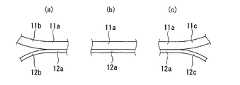
この大流路11と小流路12との関係を図2および図3を用いてさらに詳しく説明する。図2(a)は大流路11および小流路12の各々の導入部11b、12bと集合部11a、集合部12aとの境界近傍の部分拡大平面図である。また、図2(b)は大流路11および小流路12の各々の集合部11a、集合部12aの部分拡大平面図である。また、図2(c)は大流路11および小流路12の各々の集合部11a、集合部12aと流出部11c、12cとの境界近傍の部分拡大平面図である。さらに、図3は、大流路11および小流路12の各々の集合部11a、集合部12aにおける拡大断面図である。 The relationship between the
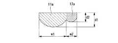
図3に示すように、各流路の底面はいずれも円弧状とされている。また、小流路12の集合部12aの深さd2は大流路11の集合部11aの深さd1よりも浅く(小さく)なっている。また、集合部12aの幅w2は集合部11aの幅w1よりも狭く(小さく)なっている。その結果、小流路12の集合部12aの断面積は大流路11の集合部11aの断面積よりも狭く(小さく)なっている。
深さd1は50μm以上であることが好ましく、幅w1は(d1×2+10)μm前後であることが好ましい。深さd2は50μm未満であることが好ましく、幅w2は(d2×2+10)μm前後であることが好ましい。また、深さd1と深さd2との比は、3:1前後であることが好ましい。As shown in FIG. 3, the bottom surfaces of the respective channels are all arc-shaped. Further, the depth d2 of the
The depth d1 is preferably 50 μm or more, and the width w1 is preferably about (d1 × 2 + 10) μm. The depth d2 is preferably less than 50 μm, and the width w2 is preferably about (d2 × 2 + 10) μm. The ratio between the depth d1 and the depth d2 is preferably around 3: 1.
基板1の小流路12の内面の一部又は全部は、親液性とされていることが好ましい。特に、集合部12aの部分が親液性とされていることが好ましい。ここで親液性とは、大流路11の導入部11cから導入される液体に対して親液性であることを意味し、当該液体が水性である場合には親水性であることを、当該液体が油性である場合は親油性であることを意味する。
これに対して、基板1の大流路11の内面の一部又は全部は、親液性が低い方が好ましい。特に、集合部11aの部分が低い親液性とされていることが好ましい。
親水性、親油性とする手段としては、薬液処理、プラズマ処理、粗面化処理等、公知の手段を適宜使用することができる。Part or all of the inner surface of the
On the other hand, it is preferable that part or all of the inner surface of the
As means for making hydrophilic and lipophilic, known means such as chemical treatment, plasma treatment, and surface roughening treatment can be appropriately used.
本実施形態の気液反応ユニットで気液反応を行わせるためには、液体を液体導入口13から大流路11に導入する。また、これと同時に、気体を気体導入口14から小流路12に導入する。導入された液体と気体とは、集合部11a、12aに達すると合流するが、その後直ちに液体は小流路12側に移行し、気体は大流路11側に移行する。そして、気液の界面が保たれた層流状態となって集合部11a、12aを移動した後、液体は小流路12の流出部12cへと、気体は大流路11の流出部11cへと流れる。そして、液体は液体流出口16から、気体は気体流出口15から各々流出する。
すなわち、集合部11a、12a内で気体と液体とが交叉することとなる。この交叉の間に、気体と液体とは充分に攪拌、混合された状態となるので、気体中の成分と液体中の成分との反応が迅速に進行する。
なお、このように気体と液体とが交叉するのは、気体よりも液体の方が、流路壁面に対する密着性が高く、そのため、液体の方が気体よりも狭い空間に向かいやすい性質を有することに基づく。小流路12の内面が親液性とされている場合、液体の小流路12への密着性がより強まるので、係る気液の交叉をより確実に進行させることができる。In order to perform a gas-liquid reaction in the gas-liquid reaction unit of the present embodiment, a liquid is introduced into the
That is, the gas and the liquid cross each other in the collecting
It should be noted that the gas and the liquid cross each other in this way because the liquid has a higher adhesion to the flow path wall surface than the gas, and therefore the liquid has a property that tends to go to a narrower space than the gas. based on. When the inner surface of the
気体と液体とを、交叉させた後に、液体流出口16と気体流出口15とから各々流出させるためには、交叉後、集合部11aと集合部12aの間で気液の界面が保たれた層流状態とする必要がある。
この層流状態を達成するためには、液体導入口13から導入する液体および気体導入口14から導入する気体の双方がある程度以上の圧力を有する必要がある。そして、この圧力を確保するためには、双方の流量を一定以上とする必要がある。
層流状態を達成するために必要な流量は、流路の断面積にもよるが、例えば、深さd1が90μm、幅w1が190μm、深さd2が60μm、幅w2が60μmの場合について、フェノールフタレイン水溶液と空気を用いて実験したところ、以下の条件で良好な層流状態が得られることが確認できた。
すなわち、液体(フェノールフタレイン水溶液)の流量を1μL/minとし、気体(空気)の流量を0.5〜2.5mL/minとした場合、および気体の流量を1mL/minとし、液体の流量を0.1〜5μL/minとした場合、各々良好な層流状態が得られた。In order to allow the gas and the liquid to cross each other and then flow out from the
In order to achieve this laminar flow state, it is necessary that both the liquid introduced from the
The flow rate required to achieve the laminar flow state depends on the cross-sectional area of the flow path. For example, when the depth d1 is 90 μm, the width w1 is 190 μm, the depth d2 is 60 μm, and the width w2 is 60 μm, When an experiment was conducted using a phenolphthalein aqueous solution and air, it was confirmed that a good laminar flow state was obtained under the following conditions.
That is, when the flow rate of liquid (phenolphthalein aqueous solution) is 1 μL / min, the flow rate of gas (air) is 0.5 to 2.5 mL / min, and the flow rate of gas is 1 mL / min, the flow rate of liquid When 0.1 was set to 0.1 to 5 μL / min, a good laminar flow state was obtained.
係る第1実施形態の気液反応ユニットを用いた分析装置は、気液反応ユニットに加えて、気液反応の結果を検知する検出器を備えるものである。
気液反応ユニットにおいては、液体、気体共に、気液反応の結果として性状が変化しうる。したがって、検出器は、流出部12cの液体、流出部11cの気体の何れを対象とするものであってもよいが、検知が容易である点から、流出部12cにおける液体の性状を検知する検出器を備えることが好ましい。
また、気液反応ユニットの流出部における流体の性状は、その場で検知しても、流出部から流出後に検知してもよい。すなわち、流出部12cにおける液体の性状を検知する場合、流出部12cの液体をその場で検知しても、流出部12cから流出した後に検知してもよい。The analyzer using the gas-liquid reaction unit of the first embodiment includes a detector that detects the result of the gas-liquid reaction in addition to the gas-liquid reaction unit.
In the gas-liquid reaction unit, the properties of both liquid and gas can change as a result of the gas-liquid reaction. Therefore, the detector may be for either the liquid in the
Moreover, the property of the fluid in the outflow part of a gas-liquid reaction unit may be detected on the spot, or may be detected after outflow from the outflow part. That is, when detecting the property of the liquid in the
検知すべき流体の性状としては、例えば気液反応により生成した化合物の濃度、気相から液相に移行した化合物の濃度、これらの化合物の濃度に連動する導電率、pH等の物性値などが挙げられる。また、検知手段としては、蛍光、光吸収等を検知する光検出手段、導電率センサ、H2O2センサ、pHセンサ、熱レンズ顕微鏡検出手段等の電気化学的検出手段等が挙げられる。The properties of the fluid to be detected include, for example, the concentration of the compound generated by the gas-liquid reaction, the concentration of the compound transferred from the gas phase to the liquid phase, the conductivity linked to the concentration of these compounds, the physical properties such as pH, etc. Can be mentioned. Examples of the detection means include light detection means for detecting fluorescence, light absorption, and the like, electrochemical detection means such as a conductivity sensor, an H2 O2 sensor, a pH sensor, and a thermal lens microscope detection means.
第1実施形態の気液反応ユニットを用いた分析装置の使用方法の一例として、気体中のアンモニアガスの濃度を求める方法を説明する。
まず、被検体としての気体を気体導入口14から導入する。また、反応試薬として、pH指示薬であるフェノールフタレイン溶液を液体導入口13から導入する。そして、流出部12cにおけるフェノールフタレイン溶液の発色を熱レンズ顕微鏡で検知する。その結果、気体中のアンモニアガスによるフェノールフタレイン溶液のpH変化を求め、この値から、気体中のアンモニアガスの濃度を求めることができる。As an example of a method of using the analyzer using the gas-liquid reaction unit of the first embodiment, a method for determining the concentration of ammonia gas in the gas will be described.
First, a gas as an object is introduced from the
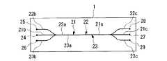
次に、本発明の第2実施形態に係る気液反応ユニットおよびこれを用いた分析装置を、図4から図6を用いて説明する。本実施形態の気液反応ユニットは、図4に示すように、基板1に設けられた大流路21と小流路22、23とを備えている。基板1の材質、形状等は、第1実施形態における基板1と同様なので説明を省略する。 Next, a gas-liquid reaction unit according to a second embodiment of the present invention and an analyzer using the same will be described with reference to FIGS. As shown in FIG. 4, the gas-liquid reaction unit of the present embodiment includes a
大流路21は、集合部21aと集合部21aの図示左側に存する導入部21bと集合部21aの図示右側に存する流出部21cとからなり、小流路22、23は、各々集合部22a、23aと集合部22a、23aの図示左側に存する導入部22b、23bと集合部22a、23aの図示右側に存する流出部22c、23cとからなっている。
そして、大流路21の集合部21aと小流路22の集合部22aとは、互いに内部の流体が接触可能な状態で隣接している。同様に、大流路21の集合部21aと小流路23の集合部23aとは、互いに内部の流体が接触可能な状態で隣接している。また、大流路21および小流路22、23の各々の導入部21b、22b、23bは、互いに接触しない独立の流路とされている。同様に、大流路21および小流路22、23の各々の流出部21c、22c、23cは、互いに接触しない独立の流路とされている。The
And the
また、大流路21の導入部21bには、基板1の外部と連通しており液体が導入される液体導入口24が設けられている。また、小流路22の導入部22bおよび小流路23の導入部23bには、各々基板1の外部と連通しており気体が導入される気体導入口25、26が設けられている。また、大流路21の流出部21cには、基板1の外部と連通しており気体が流出する気体流出口27が設けられている。また、小流路22の流出部22cおよび小流路23の流出部23cには、各々基板1の外部と連通しており液体が流出する液体流出口28、29が設けられている In addition, the
この大流路21と小流路22、23との関係を図5および図6を用いてさらに詳しく説明する。図5(a)は大流路21および小流路22、23の各々の導入部21b、22b、23bと集合部21a、22a、23aとの境界近傍の部分拡大平面図である。また、図5(b)は大流路21および小流路22、23の各々の集合部21a、22a、23aの部分拡大平面図である。また、図5(c)は大流路21および小流路22、23の各々の集合部21a、22a、23aと流出部21c、22c、23cとの境界近傍の部分拡大平面図である。さらに、図6は、大流路21および小流路22、23の各々の集合部21a、22a、23aにおける拡大断面図である。 The relationship between the
図6に示すように、各流路の底面はいずれも円弧状とされている。また、小流路22、23の集合部22a、23aの各深さd4、d5は等しく、いずれも大流路21の集合部21aの深さd3よりも浅く(小さく)なっている。また、集合部22a、23aの各幅w4、w5は等しく、いずれも集合部21aの幅w3よりも狭く(小さく)なっている。その結果、小流路22、23の集合部22a、23aの断面積は、いずれも大流路21の集合部21aの断面積よりも狭く(小さく)なっている。
深さd3は50μm以上であることが好ましく、幅w3は(d3×2+10)μm前後であることが好ましい。深さd4、d5は、いずれも50μm未満であることが好ましく、幅w4は(d4×2+10)μm前後、幅w5は(d5×2+10)μm前後であることが好ましい。また、深さd3と深さd4(d5)との比は、3:1前後であることが好ましい。As shown in FIG. 6, the bottom surfaces of the respective channels are all arc-shaped. Further, the depths d4 and d5 of the collecting
The depth d3 is preferably 50 μm or more, and the width w3 is preferably about (d3 × 2 + 10) μm. The depths d4 and d5 are both preferably less than 50 μm, the width w4 is preferably around (d4 × 2 + 10) μm, and the width w5 is preferably around (d5 × 2 + 10) μm. The ratio between the depth d3 and the depth d4 (d5) is preferably around 3: 1.
基板1の小流路22、23の内面の一部又は全部は親液性とされていることが好ましい。特に、集合部22a、23aの部分が親液性とされていることが好ましい。
これに対して、基板1の大流路21の内面の一部又は全部は、親液性が低い方が好ましい。特に、集合部21aの部分が低い親液性とされていることが好ましい。
なお、親液性の意味および親液性とする手段は上述のとおりである。Part or all of the inner surfaces of the
On the other hand, it is preferable that part or all of the inner surface of the
The meaning of lyophilicity and the means for making it lyophilic are as described above.
本実施形態の気液反応ユニットで気液反応を行わせるためには、液体を液体導入口24から大流路21に導入する。また、これと同時に、気体を気体導入口25、26から小流路22、23に導入する。導入された液体と気体とは、集合部21a、22a、23aに達すると合流するが、その後直ちに液体は両側の小流路22、23側に移行し、気体は中央の大流路21側に移行する。そして、気液の界面が保たれた層流状態となって集合部21a、22a、23aを移動した後、液体は小流路22、23の流出部22c、23へと、気体は大流路21の流出部21cへと流れる。そして、液体は液体流出口28、29から、気体は気体流出口27から各々流出する。
すなわち、集合部21a、22a、23a内で気体と液体とが交叉することとなる。この交叉の間に、気体と液体とは充分に攪拌、混合された状態となるので、気体中の成分と液体中の成分との反応が迅速に進行する。In order to perform the gas-liquid reaction in the gas-liquid reaction unit of the present embodiment, the liquid is introduced into the
That is, the gas and the liquid cross each other in the collecting
気体と液体とを交叉させた後に、液体流出口28、29と気体流出口27とから各々流出させるためには、交叉後、21a、22a、23aの間で気液の界面が保たれた層流状態とされる必要がある。
この層流状態を達成するためには、液体導入口24から導入する液体および気体導入口25、26から導入する気体の双方がある程度以上の圧力を有する必要がある。そして、この圧力を確保するためには、双方の流量を一定以上とする必要がある。
層流状態を達成するために必要な流量は、流路の断面積にもよるが、例えば、深さd3が90μm、幅w3が190μm、深さd4、d5が60μm、幅w4、w5が60μmの場合について、フェノールフタレイン水溶液と空気を用いて実験したところ、以下の条件で良好な層流状態が得られることが確認できた。
すなわち、液体(フェノールフタレイン水溶液)の流量を各々1μL/minとし、気体(空気)の流量を0.5〜2.5mL/minとした場合、および気体の流量を1mL/minとし、液体の流量を各々0.1〜5μL/minとした場合、各々良好な層流状態が得られた。In order to flow out the liquid and the
In order to achieve this laminar flow state, it is necessary that both the liquid introduced from the
The flow rate necessary to achieve the laminar flow state depends on the cross-sectional area of the flow path, but for example, the depth d3 is 90 μm, the width w3 is 190 μm, the depths d4 and d5 are 60 μm, and the widths w4 and w5 are 60 μm. When an experiment was conducted using a phenolphthalein aqueous solution and air, it was confirmed that a good laminar flow state was obtained under the following conditions.
That is, when the flow rate of liquid (phenolphthalein aqueous solution) is 1 μL / min and the flow rate of gas (air) is 0.5 to 2.5 mL / min, and the flow rate of gas is 1 mL / min, When the flow rates were 0.1 to 5 μL / min, good laminar flow conditions were obtained.
係る第2実施形態の気液反応ユニットを用いた分析装置は、気液反応ユニットに加えて、気液反応の結果を検知する検出器を備えるものである。
第1実施形態の気液反応ユニットを用いた分析装置と同様に、第2実施形態の分析装置においても、流出部22cおよび/または流出部23cにおける液体の性状を検知する検出器を備えることが好ましい。また、流出部22cおよび/または23cにおける液体の性状を検知する場合、流出部22cおよび/または流出部23cの液体をその場で検知しても、流出部22cおよび/または流出部23cから流出した後に検知してもよい。検知すべき流体の性状、検知手段も、第1実施形態の場合と同様である。The analyzer using the gas-liquid reaction unit of the second embodiment includes a detector that detects the result of the gas-liquid reaction in addition to the gas-liquid reaction unit.
Similar to the analyzer using the gas-liquid reaction unit of the first embodiment, the analyzer of the second embodiment also includes a detector that detects the property of the liquid in the
第2実施形態の気液反応ユニットを用いた分析装置の使用方法の一例として、気体中のアンモニアガスの濃度を求める方法を説明する。
まず、被検体としての気体を気体導入口25、26から導入する。また、反応試薬として、pH指示薬であるフェノールフタレイン溶液を液体導入口24から導入する。そして、流出部22c、23cの双方又は一方におけるフェノールフタレイン溶液の発色を熱レンズ顕微鏡で検知する。その結果、気体中のアンモニアガスによるフェノールフタレイン溶液のpH変化を求め、この値から、気体中のアンモニアガスの濃度を求めることができる。A method for determining the concentration of ammonia gas in the gas will be described as an example of a method for using the analyzer using the gas-liquid reaction unit of the second embodiment.
First, a gas as an object is introduced from the
次に、本発明の第3実施形態に係る気液反応ユニットおよびこれを用いた分析装置を、図7を用いて説明する。本実施形態の気液反応ユニットおよびこれを用いた分析装置は、大流路21、小流路22、23の断面形状が異なる他は、第2実施形態に係る気液反応ユニットと同じである。
図7は、本実施形態の大流路21および小流路22、23の各々の集合部21a、22a、23aにおける拡大断面図である。Next, a gas-liquid reaction unit according to a third embodiment of the present invention and an analyzer using the same will be described with reference to FIG. The gas-liquid reaction unit of this embodiment and the analyzer using the same are the same as the gas-liquid reaction unit according to the second embodiment, except that the cross-sectional shapes of the
FIG. 7 is an enlarged cross-sectional view of each of the
図7に示すように、各流路の底面はいずれも水平な直線状とされている。また、小流路22、23の集合部22a、23aの各深さd7、d8は等しく、いずれも大流路21の集合部21aの深さd6よりも浅く(小さく)なっている。また、集合部22a、23aの各幅w7、w8は等しく、いずれも集合部21aの幅w6よりも狭く(小さく)なっている。その結果、小流路22、23の集合部22a、23aの断面積は、いずれも大流路21の集合部21aの断面積よりも狭く(小さく)なっている。 As shown in FIG. 7, the bottom surfaces of the respective channels are all horizontal and linear. Further, the depths d7 and d8 of the collecting
次に、本発明の第4実施形態に係る気液反応ユニットおよびこれを用いた分析装置を、図8を用いて説明する。本実施形態の気液反応ユニットおよびこれを用いた分析装置も、大流路21、小流路22、23の断面形状が異なる他は、第2実施形態に係る気液反応ユニットと同じである。
図8は、本実施形態の大流路21および小流路22、23の各々の集合部21a、22a、23aにおける拡大断面図である。図8に示すように、各流路の底面および上面は、いずれも円弧状とされている。Next, a gas-liquid reaction unit according to a fourth embodiment of the present invention and an analyzer using the same will be described with reference to FIG. The gas-liquid reaction unit of this embodiment and the analyzer using the same are also the same as the gas-liquid reaction unit according to the second embodiment except that the cross-sectional shapes of the
FIG. 8 is an enlarged cross-sectional view of each of the
なお、上記各実施形態における大流路および小流路の数は各々1又は2であるが、いずれも3以上であってもよい。ただし、大流路と小流路とは、交互に配置されることが好ましい。
また、集合部における気液分離をより確実にするために、気相と液相との間を部分的に分離する隔壁を、たとえば集合部の底面から上面方向に向けて立設させもよい。In addition, although the number of the large flow path and the small flow path in each said embodiment is 1 or 2, respectively, all may be 3 or more. However, it is preferable that the large channel and the small channel are alternately arranged.
Further, in order to more reliably perform gas-liquid separation in the gathering portion, a partition wall that partially separates the gas phase and the liquid phase may be erected, for example, from the bottom surface of the gathering portion toward the upper surface.
11、21・・・・大流路、
12、22、23・・・・小流路、
11a、12a、21a、22a、23a・・・・集合部、
11b、12b、21b、22b、23b・・・・導入部、
11c、12c、21c、22c、23c・・・・流出部、
13、24・・・・、液体導入口、
14、25、26・・・・気体導入口、
15、27・・・・気体流出口、
16、28、29・・・・液体流出口
11, 21 .... Large flow path,
12, 22, 23... Small flow path,
11a, 12a, 21a, 22a, 23a,...
11b, 12b, 21b, 22b, 23b... Introduction part,
11c, 12c, 21c, 22c, 23c... Outflow part,
13, 24 ..., liquid inlet,
14, 25, 26... Gas introduction port,
15, 27 ... Gas outlet,
16, 28, 29, ... Liquid outlet
Claims (3)
Translated fromJapanese前記大流路の集合部と小流路の集合部とは、互いに内部の流体が接触可能な状態で隣接し、かつ該小流路の集合部の深さおよび断面積が該大流路の集合部の深さおよび断面積よりも小さく、
前記大流路および小流路の各々の導入部は、いずれも他の導入部と接触しない独立の流路であり、
前記大流路および小流路の各々の流出部は、いずれも他の流出部と接触しない独立の流路であり、
前記大流路の導入部には液体が導入される液体導入口が設けられており、
前記小流路の導入部には気体が導入される気体導入口が設けられており、
前記大流路の流出部には気体が流出する気体流出口が設けられており、
前記小流路の流出部には液体が流出する液体流出口が設けられており、
前記気体導入口に気体を導入し、前記液体導入口に液体を導入することにより、
前記大流路の集合部と小流路の集合部において気体と液体とが交叉し、その後前記気体流出口から気体が流出し、前記液体流出口から液体が流出するように構成されていることを特徴とする気液反応ユニット。One or more large flow paths and one or more small flow paths, and each of the large flow paths and the small flow paths is disposed on one end side of the collecting portion and the collecting portion and on the other end side of the collecting portion. The existing outflow part,
The large flow path collecting portion and the small flow path collecting portion are adjacent to each other so that the fluid inside can be in contact with each other, and the depth and cross-sectional area of the small flow path collecting portion are Smaller than the depth and cross-sectional area of the assembly,
Each introduction part of the large flow path and the small flow path is an independent flow path that does not contact any other introduction part,
Each outflow part of the large flow path and the small flow path is an independent flow path that does not contact any other outflow part,
A liquid introduction port through which liquid is introduced is provided in the introduction portion of the large flow path,
A gas introduction port through which gas is introduced is provided in the introduction portion of the small flow path,
The outflow part of the large flow path is provided with a gas outlet through which gas flows out,
The outflow part of the small flow path is provided with a liquid outlet through which liquid flows out,
By introducing gas into the gas inlet and introducing liquid into the liquid inlet,
Gas and liquid intersect each other at the large flow path and small flow path, and then the gas flows out from the gas outlet and the liquid flows out from the liquid outlet . A gas-liquid reaction unit characterized by
An analyzer comprising the gas-liquid reaction unit according to claim 1 and a detection means for detecting the property of the liquid in the outflow portion of the small flow path.
Priority Applications (1)
| Application Number | Priority Date | Filing Date | Title |
|---|---|---|---|
| JP2004152073AJP4555609B2 (en) | 2004-05-21 | 2004-05-21 | Gas-liquid reaction unit and analyzer |
Applications Claiming Priority (1)
| Application Number | Priority Date | Filing Date | Title |
|---|---|---|---|
| JP2004152073AJP4555609B2 (en) | 2004-05-21 | 2004-05-21 | Gas-liquid reaction unit and analyzer |
Publications (2)
| Publication Number | Publication Date |
|---|---|
| JP2005329364A JP2005329364A (en) | 2005-12-02 |
| JP4555609B2true JP4555609B2 (en) | 2010-10-06 |
Family
ID=35484355
Family Applications (1)
| Application Number | Title | Priority Date | Filing Date |
|---|---|---|---|
| JP2004152073AExpired - Fee RelatedJP4555609B2 (en) | 2004-05-21 | 2004-05-21 | Gas-liquid reaction unit and analyzer |
Country Status (1)
| Country | Link |
|---|---|
| JP (1) | JP4555609B2 (en) |
Families Citing this family (4)
| Publication number | Priority date | Publication date | Assignee | Title |
|---|---|---|---|---|
| JP4555610B2 (en)* | 2004-05-21 | 2010-10-06 | 東亜ディーケーケー株式会社 | Gas-liquid reaction unit and analyzer |
| JP4528585B2 (en)* | 2004-09-07 | 2010-08-18 | 株式会社島津製作所 | Two-phase flow stabilization chip |
| JP5765722B2 (en)* | 2009-03-31 | 2015-08-19 | マイクロ化学技研株式会社 | Microchannel chip and gas-liquid phase separation method using the same |
| GB2505706A (en)* | 2012-09-10 | 2014-03-12 | Univ Leiden | Apparatus comprising meniscus alignment barriers |
Family Cites Families (4)
| Publication number | Priority date | Publication date | Assignee | Title |
|---|---|---|---|---|
| CN1087960C (en)* | 1994-10-22 | 2002-07-24 | 研究中心实验室(有限) | Method and apparatus for diffusive transfer between immiscible fluids |
| AU6541596A (en)* | 1995-06-16 | 1997-01-15 | University Of Washington | Microfabricated differential extraction device and method |
| GB0030929D0 (en)* | 2000-12-19 | 2001-01-31 | Inverness Medical Ltd | Analyte measurement |
| JP4555610B2 (en)* | 2004-05-21 | 2010-10-06 | 東亜ディーケーケー株式会社 | Gas-liquid reaction unit and analyzer |
- 2004
- 2004-05-21JPJP2004152073Apatent/JP4555609B2/ennot_activeExpired - Fee Related
Also Published As
| Publication number | Publication date |
|---|---|
| JP2005329364A (en) | 2005-12-02 |
Similar Documents
| Publication | Publication Date | Title |
|---|---|---|
| Sin et al. | System integration-A major step toward lab on a chip | |
| Guo et al. | Application of microfluidic “lab-on-a-chip” for the detection of mycotoxins in foods | |
| JP5663574B2 (en) | Microfluidic analysis platform | |
| CN108704677B (en) | Microfluidic chip and analytical instrument comprising same | |
| Sato et al. | Microchip-based chemical and biochemical analysis systems | |
| EP1487581B1 (en) | Microfluidic channel network device | |
| US6857449B1 (en) | Multi-layer microfluidic devices | |
| Sato et al. | Integration of chemical and biochemical analysis systems into a glass microchip | |
| KR100878229B1 (en) | Fluid Analysis Chip | |
| US20090155125A1 (en) | Microchip | |
| US8482734B2 (en) | Centrifugal device | |
| CN215843055U (en) | Chip is flowed in accuse step by step | |
| CN108761055B (en) | Microfluidic chip and analytical instrument with same | |
| CN111013677B (en) | Microfluidic chip, detection device and detection method | |
| WO2008047875A1 (en) | Microanalysis measuring apparatus and microanalysis measuring method using the same | |
| US20210123903A1 (en) | Micro-fluidic Chip and Analytical Instrument Provided with the Micro-fluidic Chip | |
| KR102363347B1 (en) | Modular microfluidic device and method for fluid analisys using the same | |
| JP2007216123A (en) | Micro-channel chip | |
| JP5376427B2 (en) | Analytical device | |
| US9770717B1 (en) | Microfluidic chip with bead integration system | |
| CN207268741U (en) | Multi-channel microfluidic board | |
| Zuo et al. | An integrated microfluidic system for multi-target biochemical analysis of a single drop of blood | |
| JP4555609B2 (en) | Gas-liquid reaction unit and analyzer | |
| KR100824209B1 (en) | Manual Microfluidic Cleaning Device Using Capillary Force | |
| JP4555610B2 (en) | Gas-liquid reaction unit and analyzer |
Legal Events
| Date | Code | Title | Description |
|---|---|---|---|
| A621 | Written request for application examination | Free format text:JAPANESE INTERMEDIATE CODE: A621 Effective date:20070220 | |
| A977 | Report on retrieval | Free format text:JAPANESE INTERMEDIATE CODE: A971007 Effective date:20090323 | |
| A131 | Notification of reasons for refusal | Free format text:JAPANESE INTERMEDIATE CODE: A131 Effective date:20090421 | |
| A521 | Request for written amendment filed | Free format text:JAPANESE INTERMEDIATE CODE: A523 Effective date:20090616 | |
| TRDD | Decision of grant or rejection written | ||
| A01 | Written decision to grant a patent or to grant a registration (utility model) | Free format text:JAPANESE INTERMEDIATE CODE: A01 Effective date:20100629 | |
| A01 | Written decision to grant a patent or to grant a registration (utility model) | Free format text:JAPANESE INTERMEDIATE CODE: A01 | |
| A61 | First payment of annual fees (during grant procedure) | Free format text:JAPANESE INTERMEDIATE CODE: A61 Effective date:20100716 | |
| FPAY | Renewal fee payment (event date is renewal date of database) | Free format text:PAYMENT UNTIL: 20130723 Year of fee payment:3 | |
| R150 | Certificate of patent or registration of utility model | Ref document number:4555609 Country of ref document:JP Free format text:JAPANESE INTERMEDIATE CODE: R150 Free format text:JAPANESE INTERMEDIATE CODE: R150 | |
| FPAY | Renewal fee payment (event date is renewal date of database) | Free format text:PAYMENT UNTIL: 20130723 Year of fee payment:3 | |
| S533 | Written request for registration of change of name | Free format text:JAPANESE INTERMEDIATE CODE: R313533 | |
| R350 | Written notification of registration of transfer | Free format text:JAPANESE INTERMEDIATE CODE: R350 | |
| R250 | Receipt of annual fees | Free format text:JAPANESE INTERMEDIATE CODE: R250 | |
| R250 | Receipt of annual fees | Free format text:JAPANESE INTERMEDIATE CODE: R250 | |
| R250 | Receipt of annual fees | Free format text:JAPANESE INTERMEDIATE CODE: R250 | |
| R250 | Receipt of annual fees | Free format text:JAPANESE INTERMEDIATE CODE: R250 | |
| R250 | Receipt of annual fees | Free format text:JAPANESE INTERMEDIATE CODE: R250 | |
| S111 | Request for change of ownership or part of ownership | Free format text:JAPANESE INTERMEDIATE CODE: R313117 | |
| R360 | Written notification for declining of transfer of rights | Free format text:JAPANESE INTERMEDIATE CODE: R360 | |
| R360 | Written notification for declining of transfer of rights | Free format text:JAPANESE INTERMEDIATE CODE: R360 | |
| R371 | Transfer withdrawn | Free format text:JAPANESE INTERMEDIATE CODE: R371 | |
| S111 | Request for change of ownership or part of ownership | Free format text:JAPANESE INTERMEDIATE CODE: R313117 | |
| R350 | Written notification of registration of transfer | Free format text:JAPANESE INTERMEDIATE CODE: R350 | |
| R250 | Receipt of annual fees | Free format text:JAPANESE INTERMEDIATE CODE: R250 | |
| R250 | Receipt of annual fees | Free format text:JAPANESE INTERMEDIATE CODE: R250 | |
| R250 | Receipt of annual fees | Free format text:JAPANESE INTERMEDIATE CODE: R250 | |
| R250 | Receipt of annual fees | Free format text:JAPANESE INTERMEDIATE CODE: R250 | |
| LAPS | Cancellation because of no payment of annual fees |