JP4555607B2 - Lens barrel feeding mechanism - Google Patents
Lens barrel feeding mechanismDownload PDFInfo
- Publication number
- JP4555607B2 JP4555607B2JP2004144642AJP2004144642AJP4555607B2JP 4555607 B2JP4555607 B2JP 4555607B2JP 2004144642 AJP2004144642 AJP 2004144642AJP 2004144642 AJP2004144642 AJP 2004144642AJP 4555607 B2JP4555607 B2JP 4555607B2
- Authority
- JP
- Japan
- Prior art keywords
- cylinder
- cam
- lens
- lens group
- feeding mechanism
- Prior art date
- Legal status (The legal status is an assumption and is not a legal conclusion. Google has not performed a legal analysis and makes no representation as to the accuracy of the status listed.)
- Expired - Fee Related
Links
Images


Classifications
- G—PHYSICS
- G02—OPTICS
- G02B—OPTICAL ELEMENTS, SYSTEMS OR APPARATUS
- G02B7/00—Mountings, adjusting means, or light-tight connections, for optical elements
- G02B7/02—Mountings, adjusting means, or light-tight connections, for optical elements for lenses
- G02B7/021—Mountings, adjusting means, or light-tight connections, for optical elements for lenses for more than one lens
- G—PHYSICS
- G02—OPTICS
- G02B—OPTICAL ELEMENTS, SYSTEMS OR APPARATUS
- G02B7/00—Mountings, adjusting means, or light-tight connections, for optical elements
- G02B7/02—Mountings, adjusting means, or light-tight connections, for optical elements for lenses
- G02B7/04—Mountings, adjusting means, or light-tight connections, for optical elements for lenses with mechanism for focusing or varying magnification
- G02B7/10—Mountings, adjusting means, or light-tight connections, for optical elements for lenses with mechanism for focusing or varying magnification by relative axial movement of several lenses, e.g. of varifocal objective lens
- G02B7/102—Mountings, adjusting means, or light-tight connections, for optical elements for lenses with mechanism for focusing or varying magnification by relative axial movement of several lenses, e.g. of varifocal objective lens controlled by a microcomputer
- G—PHYSICS
- G03—PHOTOGRAPHY; CINEMATOGRAPHY; ANALOGOUS TECHNIQUES USING WAVES OTHER THAN OPTICAL WAVES; ELECTROGRAPHY; HOLOGRAPHY
- G03B—APPARATUS OR ARRANGEMENTS FOR TAKING PHOTOGRAPHS OR FOR PROJECTING OR VIEWING THEM; APPARATUS OR ARRANGEMENTS EMPLOYING ANALOGOUS TECHNIQUES USING WAVES OTHER THAN OPTICAL WAVES; ACCESSORIES THEREFOR
- G03B17/00—Details of cameras or camera bodies; Accessories therefor
- G03B17/02—Bodies
- G03B17/04—Bodies collapsible, foldable or extensible, e.g. book type
- H—ELECTRICITY
- H04—ELECTRIC COMMUNICATION TECHNIQUE
- H04N—PICTORIAL COMMUNICATION, e.g. TELEVISION
- H04N23/00—Cameras or camera modules comprising electronic image sensors; Control thereof
- H04N23/50—Constructional details
- H04N23/55—Optical parts specially adapted for electronic image sensors; Mounting thereof
Landscapes
- Physics & Mathematics (AREA)
- General Physics & Mathematics (AREA)
- Engineering & Computer Science (AREA)
- Optics & Photonics (AREA)
- Multimedia (AREA)
- Signal Processing (AREA)
- General Engineering & Computer Science (AREA)
- Lens Barrels (AREA)
- Studio Devices (AREA)
- Structure And Mechanism Of Cameras (AREA)
Description
Translated fromJapanese本発明は、収納位置と撮影位置を有する沈胴式のレンズ鏡筒に関する。 The present invention relates to a retractable lens barrel having a storage position and a photographing position.
近年カメラの小型化の要求はとどまるところが無く、特に携帯性の向上のためにカメラ薄型化が重要視されており、カメラ薄型化の制約となっているレンズ鏡筒ユニットの薄型化が求められている。レンズ鏡筒ユニットの薄型化の手法としては、不使用時にレンズ群や撮像デバイスの間隔を減少させてレンズ鏡筒を沈胴して収納することが従来より実施されている。 In recent years, there has been no limit to the demand for camera miniaturization, and in particular, thinning of the camera has been regarded as important in order to improve portability, and the lens barrel unit, which is a constraint for thinning the camera, has been demanded. Yes. As a technique for reducing the thickness of the lens barrel unit, it has been conventionally practiced to retract the lens barrel by retracting the lens group and the imaging device when not in use.
また、特許文献1のように、収納状態では撮影レンズ群の一部が撮影光軸から退避して沈胴されるものがあり、被写体側から2番目のレンズ群を退避して沈胴する方式が実施されている。さらに、特許文献2のように、レンズ群の移動量を犠牲にすることなくレンズ繰出し用のカム筒を薄型化する手法もある。
レンズ鏡筒の薄型化が達成されたとしても、レンズの光学性能は維持する必要がある。通常ズームデジタルカメラにおいては撮影光学系が3つのレンズ群により構成されている場合が多く、それぞれのレンズ群の撮影光軸方向の移動によりズーム動作や沈胴動作が行われている。この場合、レンズ群の撮影光軸のずれ特に被写体側から1番目のレンズ群と2番目のレンズ群との光軸のずれ、または1番目のレンズ群と2番目のレンズ群との相対的な光軸の傾きは光学性能に大きな影響を与えるため、特許文献1または2の実施形態のように2番目のレンズ群のみを個別の退避機構によって退避収納する手法は、レンズ群の傾きや平行偏心が発生しやすく光学性能の維持が困難である。 Even if the lens barrel is made thinner, it is necessary to maintain the optical performance of the lens. Usually, in a zoom digital camera, a photographing optical system is often composed of three lens groups, and a zoom operation and a retracting operation are performed by movement of each lens group in the photographing optical axis direction. In this case, the deviation of the photographing optical axis of the lens group, particularly the deviation of the optical axis between the first lens group and the second lens group from the subject side, or the relative relationship between the first lens group and the second lens group. Since the tilt of the optical axis has a great influence on the optical performance, the method of retracting and storing only the second lens group by an individual retracting mechanism as in the embodiments of
本発明は、上記課題に鑑み、光学性能に影響が大きいレンズ群どうしの相対位置関係を維持するとともにそれらのレンズ群をまとめて退避収納する繰出し機構を実現し、レンズ鏡筒の薄型化を達成することを目的とする。 In view of the above problems, the present invention realizes a feeding mechanism that maintains the relative positional relationship between lens groups that have a large influence on optical performance and retracts and stores these lens groups together, thereby achieving a thinner lens barrel. The purpose is to do.
請求項1に記載のレンズ鏡筒繰出し機構の発明は、被写体側から順に前方側レンズ群、後方側レンズ群、撮像デバイスからなる撮影光学系を繰出し保持するレンズ鏡筒繰出し機構であって、収納位置においては、撮影光軸上にある後方側レンズ群および撮像デバイスの側方であって撮影光軸から離れた位置に前方側レンズ群を収納し、撮影位置においては、前方側レンズ群とを繰り出すとともに、撮影光軸上に位置させるように撮影光学系を繰出し保持するレンズ鏡筒繰出し機構において、内周面に複数のカム溝が形成され固定された固定筒と、外周に前記固定筒のカム溝と係合する少なくとも一つのカムフォロアを有し、前記撮影光軸に対して偏心した平行な軸を中心に回転する回転筒と、外周に前記固定筒のカム溝と係合する少なくとも一つのカムフォロアを有し、前記回転筒に対して回転可能に支持され前方側レンズ群を保持する規制筒と、前記回転筒に回転力を与え、前記規制筒を前記回転筒の回転軸まわりに回転運動及び前記回転筒の回転軸方向に沿って推進運動させる駆動機構と、を備え、前記回転運動により、前方側レンズ群の中心軸を前記撮影光軸に一致させるように駆動し、前記推進運動により、前方側レンズ群を後方側レンズ群の前方に位置させるように駆動すること、を特徴とする。The lens barrel feeding mechanism according to
請求項2に記載のレンズ鏡筒繰出し機構の発明は、請求項1記載のレンズ鏡筒繰出し機構において、収納位置から、収納位置と撮影位置との間の所定位置までは、前記規制筒が前記回転運動をすることなく、前記推進運動のみを行うように、前記固定筒のカム溝が形成されていることを特徴とする。The lens barrel feeding mechanism according to a second aspect of the present invention is the lens barrel feeding mechanism accordingto the first aspect, wherein the regulating cylinder is located from the storage position to a predetermined position between the storage position and the photographing position. A cam groove of the fixed cylinder is formedso as to perform only the propulsion movement without rotating .
請求項3に記載のレンズ鏡筒繰出し機構の発明は、請求項1または2記載のレンズ鏡筒繰出し機構において、前記固定筒の複数のカム溝は互いに交差しないように形成されていることを特徴とする。A lens barrel feeding mechanism according to athird aspect of the invention is characterized in that in the lens barrel feeding mechanism according to the firstor second aspect , the plurality of cam grooves of the fixed barrel are formed so as not to cross each other. And
請求項4に記載のレンズ鏡筒繰出し機構の発明は、請求項1または2記載のレンズ鏡筒繰出し機構において、前記回転筒のカムフォロアに係合する前記固定筒のカム溝と前記規制筒のカムフォロアに係合する前記固定筒のカム溝とが、同じカム軌跡を共有する領域を持つように配置し、それぞれのカム溝の深さを互いに異なるように形成したことを特徴とする。A lens barrel feeding mechanism according to afourth aspect of the present invention is the lens barrel feeding mechanism according to claim 1or 2 , wherein the cam groove of the fixed barrel and the cam follower of the restricting barrel are engaged with the cam follower of the rotating barrel. The cam groove of the fixed cylinder that engages with the cam groove is disposed so as to have a region sharing the same cam locus, and the depth of each cam groove is different from each other.
請求項5に記載のレンズ鏡筒繰出し機構の発明は、請求項4記載のレンズ鏡筒繰出し機構において、前記回転筒のカムフォロア近傍または前記規制筒のカムフォロア近傍に、それぞれのカムフォロアが係合するカム溝とほぼ係合する形状を有する突起部をそれぞれ前記回転筒または前記規制筒に設けたことを特徴とする。The lens barrel feeding mechanism according to
請求項6に記載のレンズ鏡筒繰出し機構の発明は、請求項1ないし5のいずれか1項記載のレンズ鏡筒繰出し機構において、前記回転筒の回転によって撮影位置に繰出された撮影光学系が、さらなる回転筒の回転によって焦点距離が可変になるように構成されたことを特徴とする。The lens barrel feeding mechanism according to asixth aspect of the present invention is the lens barrel feeding mechanism according to any one of the first tofifth aspects, wherein the photographing optical system fed to the photographing position by the rotation of the rotating barrel is provided. Further, the focal length is made variable by further rotation of the rotating cylinder.
請求項7に記載のレンズ鏡筒繰出し機構の発明は、請求項6記載のレンズ鏡筒繰出し機構において、撮影光学系は3つのレンズ群より構成され、規制筒は、前方側レンズ群である、被写体側より1番目のレンズ群と2番目のレンズ群を保持していることを特徴とする。The invention of the lens barrel feeding mechanism according to
請求項1に記載の発明によれば、撮影光学系を保持した規制筒が回転軸まわりの回転動作と回転軸方向の繰出し動作を任意に組合せて行うことができる。例えば、撮像デバイスの側方に収納されたレンズを前記回転動作と前記繰出し動作によって撮像デバイスの前方に配置することができる。従って、撮影時に撮像デバイスの前方に配置されるレンズを撮像デバイスの側方に収納できるので、収納時にレンズ鏡筒の薄型化を図ることができる。 According to the first aspect of the present invention, the restriction cylinder holding the photographing optical system can perform any combination of the rotation operation around the rotation axis and the feeding operation in the rotation axis direction. For example, a lens housed on the side of the imaging device can be disposed in front of the imaging device by the rotation operation and the extension operation. Accordingly, since the lens arranged in front of the imaging device at the time of photographing can be stored on the side of the imaging device, the lens barrel can be thinned at the time of storage.
請求項2に記載の発明によれば、収納位置で撮影光学系の側方に配置されている撮像デバイス等の構成部品と干渉することなく光軸方向に撮影光学系を直進繰出しした後に回転動作を行うことができるので、撮影光学系の周囲に隙間を少なくして構成部品を配置することができ、レンズ鏡筒の小型化を図ることができる。 According to the second aspect of the present invention, the rotation operation is performed after the photographing optical system is linearly fed out in the optical axis direction without interfering with components such as an imaging device disposed on the side of the photographing optical system at the storage position. Therefore, it is possible to arrange the components with a small gap around the photographing optical system, and to reduce the size of the lens barrel.
請求項3に記載の発明によれば、カム溝が交差することがないので、カムフォロアが所望のカム溝から脱輪して作動に不具合が生じることがなくなる。According to thethird aspect of the present invention, the cam grooves do not intersect with each other, so that the cam follower does not deviate from the desired cam groove and malfunctions do not occur.
請求項4に記載の発明によれば、回転筒用のカム溝と規制筒用のカム溝が同じカム軌跡を共有する領域を持つようにしても、それぞれのカム溝の深さが異なるため、カムフォロアをカム溝から脱輪することなくガイドすることができる。回転筒用のカム溝と規制筒用のカム溝とで一部重複したカム軌跡を持たせることができれば、固定筒のカム溝配置範囲を広く設定することができて設計自由度が大きくなる。According to the invention of
請求項5に記載の発明によれば、カム溝の重複した領域で回転筒もしくは規制筒のカムフォロアがカム溝から少し逸れて作動負荷変動が生じることを防止することができ、回転筒もしくは規制筒をスムーズに動かすことができる。According to thefifth aspect of the present invention, it is possible to prevent the cam follower of the rotating cylinder or the regulating cylinder from slightly deviating from the cam groove in the region where the cam grooves overlap, and to prevent the operating load from changing. Can move smoothly.
請求項6に記載の発明によれば、回転筒の回転によって収納位置から撮影位置まで撮影光学系を駆動した後に、引き続いて回転筒を回転させることによりズーム動作を行うことができるので、沈胴動作やズーム動作の制御が行いやすい。According to thesixth aspect of the present invention, the zooming operation can be performed by subsequently rotating the rotating cylinder after the imaging optical system is driven from the storage position to the imaging position by the rotation of the rotating cylinder. And zoom operation is easy to control.
請求項7に記載の発明によれば、光学性能に影響が大きい被写体側より1番目のレンズ群と2番目のレンズ群どうしの相対位置関係を維持しつつ、それらのレンズ群をまとめて退避収納することができるため、レンズ鏡筒の光学性能を維持しながら薄型化を図ることができる。According to theseventh aspect of the present invention, while maintaining the relative positional relationship between the first lens group and the second lens group from the subject side that has a great influence on the optical performance, the lens groups are collectively retracted and stored. Therefore, it is possible to reduce the thickness while maintaining the optical performance of the lens barrel.
図1ないし図21について本実施形態のレンズ鏡筒の全体構成を説明する。この実施形態はデジタルカメラ用のズームレンズ鏡筒に本発明を適用したものである。 The overall configuration of the lens barrel of the present embodiment will be described with reference to FIGS. In this embodiment, the present invention is applied to a zoom lens barrel for a digital camera.
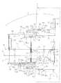
図1に広角側の撮影位置におけるレンズ鏡筒2の断面図を示す。撮影光学系は被写体側から順に第1レンズ群31、第2レンズ群32、第3レンズ群33、ローパスフィルタ34、CCD(撮像デバイス)35からなっている。撮影光学系の光軸はJ1である。撮影光軸J1はレンズ鏡筒の中心軸J2と平行であり、中心軸J2とは偏心している。ズーミングは第1レンズ群31と第2レンズ群32を撮影光軸J1方向にそれぞれ移動させることにより行い、フォーカシングは第3レンズ群33を撮影光軸J1方向に移動させることによって行う。被写体側から第1レンズ群31、第2レンズ群32、第3レンズ群33を通った光束はローパスフィルタ34を通ってCCD35に導かれる。なお、以下の説明中で「光軸方向」という記載は、特に断りがなければ撮影光軸J1と平行の方向を意味するものとする。 FIG. 1 shows a cross-sectional view of the
固定筒61はボディ本体1に固定されており、固定筒61の後方にはCCDホルダ21が固定筒61の開口を覆うように固定されている。CCDホルダ21にはCCD35前方の開口部21aにローパスフィルタ34が接着支持されている。また、CCD35は放熱板22と一体支持されておりCCD35はその放熱板22を介してCCDホルダ21に固定されている。放熱板22後方にはCCD35で生成した電気信号を転送するためのCCD用フレキシブルプリント基板23が配置される。 The fixed
フォーカシングを行う第3レンズ群33と第3レンズ群を駆動するフォーカス駆動機構3はCCDホルダ21に対して組込まれている。図2にフォーカス駆動機構3の断面図を示す。第3レンズ群33を支持する第3レンズ枠41はCCDホルダ21に設けられた一対のガイド軸A42とガイド軸B43によって光軸方向に摺動可能に支持されている。ガイド軸A42は第3レンズ枠41のメインのガイド軸でガイド軸B43は第3レンズ枠41の回転規制用であり、第3レンズ枠41に形成したガイド穴41aと41bと摺動可能に嵌っている。
フォーカスモータ44は固定筒61の内部で第3レンズ群33とCCD35の側方に配置されCCDホルダ21に対して固定されている。フォーカスモータ44の回転駆動力は、フォーカスモータギア45からフォーカスギア46、47を介して送りねじ48に伝達され、送りねじ48とナット49の蝶合関係により第3レンズ枠41が光軸方向に進退される。フォーカスモータ44の回転駆動力はフォーカスギア46、47によって減速されるため、送りねじ48は十分な回転トルクを得ることができる。第3レンズ枠41は第3レンズ枠ばね50によって光軸方向に付勢されている。フォーカスモータ44はCCDホルダ21後方に配設したレンズ駆動用フレキシブルプリント基板51を介してカメラの制御回路により制御される。The
The
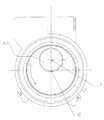
図3に撮影位置におけるレンズ鏡筒2の正面透視図を示す。固定筒61の上部にはズームモータ81と減速ギア列82が配置されている。ズームモータ81の駆動力は減速ギア列82を介してズームギア83に伝達される。ズームギア83は光軸方向と平行なギア軸84によって固定筒61に対し回転可能に支持されている。ズームモータ81、減速ギア82、ズームギア83が、レンズ鏡筒2の繰出し機構における駆動機構部である。ズームモータ81はCCDホルダ21後方に配設したレンズ駆動用フレキシブルプリント基板51を介してカメラの制御回路により制御される。 FIG. 3 shows a front perspective view of the
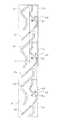
図4に固定筒61の外周面側から見た展開図を示す。固定筒61の内周には回転筒62をガイドする3本のカム溝61aと規制筒63をガイドする3本のカム溝61bが形成されている。規制筒63のカム溝61aは回転筒62のカム溝61bより深く形成されている。両カム溝61a、61bは同じカム軌跡を共有する領域61cを有しており、この領域61cでは図5に示すように2段形状のカム溝になっている。 FIG. 4 shows a development view seen from the outer peripheral surface side of the fixed
図6に回転筒62の外周面側から見た展開図を示す。回転筒62は固定筒61の内周側に位置し、回転筒62に設けられた穴部62aには3つの回転筒カムフォロアピン64が挿入されており固定筒61のカム溝61aと係合する。また、回転筒62の外周には、挿入された3つの回転筒カムフォロアピン64の近傍位置に固定筒61のカム溝61aとほぼ係合する形状を有する突起部62bが形成されている。この突起部62bの機能は後述する。回転筒62の外周部にはズームギア83と噛みあうギア部62cが設けられており、ズームモータ81、減速ギア82、ズームギア83からなる駆動機構の回転駆動力が伝達される。ズームギア83の回転によって回転筒62が中心軸J2まわりに回転すると回転筒62は固定筒61のカム溝61aに沿って繰出し繰込みされる。 FIG. 6 is a development view seen from the outer peripheral surface side of the
図7に規制筒63の外周面側から見た展開図を示す。規制筒63は回転筒62の内周側に位置し、規制筒63の外周に設けられた爪部63aが回転筒62の内周に設けられた溝部62dと係合し、回転筒62に対して相対的に光軸方向への動きは規制されるが互いに回転可能に支持されている。規制筒63の外周には3つのカムフォロア63bが形成されて固定筒61のカム溝61bと係合する。規制筒63のカムフォロア63bは断面形状が図8に示すように平行四辺形になっており、固定筒61のカム溝61bの直線領域61d、61eと係合する際にはカムフォロア63bの平面63cが係合し、固定筒61のカム溝61bの斜面領域61cと係合する際にはカムフォロア63bの平面63dが係合する。 FIG. 7 shows a developed view seen from the outer peripheral surface side of the regulating
図9にカム筒65の外周面側から見た展開図を示す。カム筒65は規制筒の内周側に位置し、外周に3つのカムフォロア65aが形成されている。カムフォロア65aは規制筒63の内周に設けられたカム溝63eと係合し、カム筒65は規制筒63との相対回転によって、規制筒63のカム溝63eによって繰出し繰込み動作を行う。また、カム筒65に設けられた穴部65bには3つのカム筒ガイド軸66が挿入されており、このカム筒ガイド軸66は規制筒63の穴部63fを貫通して回転筒62内周部の光軸方向に設けられた直進溝62eと係合している。これにより、カム筒65と回転筒62は相対回転が不能であるが光軸方向には相対的に動くことができる。 FIG. 9 is a development view seen from the outer peripheral surface side of the
すなわち、回転筒62と規制筒63とが相対回転をすれば、カム筒65が規制筒63のカム溝63eに沿って繰出し繰込みされる構成となる。 That is, when the
図10に直進筒67の外周面側から見た展開図を示す。直進筒67はカム筒65の内側に位置し、カム筒65の内周面に設けられた爪部65cが直進筒67の外周に設けられた突起部67a、67bに挟み込まれることにより、相対的に光軸方向への動きは規制されるが互いに回転可能に支持されている。直進筒67の外周面側に設けられたガイド爪部67cは規制筒63の内周部の光軸方向に設けられた直進溝63gと係合する。これにより、直進筒67と規制筒63は相対回転が不能であるが光軸方向には相対的に動くことができる。 FIG. 10 is a development view seen from the outer peripheral surface side of the
図11に第1レンズ枠68の外周面側から見た展開図を示す。第1レンズ枠68はカム筒65の内側に位置し、第1レンズ群31を支持している。第1レンズ枠68に設けられた穴部68aには3つの第1レンズ枠カムフォロアピン69が挿入されており、第1レンズ枠カムフォロアピンの外周側のカムフォロア部69aはカム筒65の内周に設けられたカム溝65dと係合する。また、第1レンズ枠カムフォロアピン69の内周側のガイド部69bは直進筒67の光軸方向に設けられた直進ガイド穴67dと係合する。これにより、第1レンズ枠68は、カム筒65と直進筒67との相対回転さらにはカム筒65と規制筒63との相対回転によって、直進筒67および規制筒63に対して相対回転することなく光軸方向にカム筒65のカム溝65dに沿って繰出し繰込みされる構成となる。 FIG. 11 is a development view seen from the outer peripheral surface side of the
図12に第2レンズ枠70の外周面側から見た展開図を示す。第2レンズ枠70は直進筒67の内側に位置し、第2レンズ群32を支持している。第2レンズ群70の外周面には3つのカムフォロア70aが形成されており、カムフォロア70aはカム筒65の内周に設けられたカム溝65eと係合する。また、第2レンズ枠70のカムフォロア70aの根元部70bは直進筒67の光軸方向に設けられた直進ガイド穴67eと係合する。これにより、第2レンズ枠70は、カム筒65と直進筒67との相対回転さらにはカム筒65と規制筒63との相対回転によって、直進筒67および規制筒63に対して相対回転することなく光軸方向にカム筒65のカム溝65eに沿って繰出し繰込みされる構成となる。 FIG. 12 is a development view seen from the outer peripheral surface side of the
第2レンズ枠70には被写体側からの入射光を遮るためのシャッタユニット71が取り付けられる。シャッタユニット71に設けられたアクチュエータ71aをカメラの制御回路と接続するためのシャッタ用フレキシブルプリント基板72が、シャッタユニット71からレンズ鏡筒2の内部を通ってCCDホルダ21後方に配設したレンズ駆動用フレキシブルプリント基板51に接続される。 A
第2レンズ枠70と第1レンズ枠68の間には群間付勢ばね73が設けられ、第2レンズ群70と第1レンズ群68を光軸方向に沿って互いに引き離す方向に付勢している。
これによって、第1レンズ枠68とカム筒65のカム係合部のがたと第2レンズ枠70とカム筒65のカム係合部のがたをなくすことができ、光学性能の安定化を図ることができる。An
As a result, the rattling of the cam engaging portion of the
ここで、レンズ鏡筒2の収納位置から撮影位置への繰出し動作について説明する。 Here, the feeding operation from the storage position of the
図13に収納位置におけるレンズ鏡筒2の断面図を示す。また、図14に収納位置におけるレンズ鏡筒2の正面透視図を示す。第1レンズ群31と第2レンズ群32の中心軸はJ3であり、第3レンズ群33とローパスフィルタ34とCCD35の側方、かつフォーカス駆動機構3の側方で撮影光軸J1から離れた位置に収納されている。つまり、第1レンズ群31と第2レンズ群32、第3レンズ群33とローパスフィルタ34とCCD35、フォーカス駆動機構3の3つのブロックは光軸に垂直な略同一の平面上に収納されている。 FIG. 13 shows a cross-sectional view of the
第1レンズ群31と第2レンズ群32はレンズ鏡筒2の中心軸J2を中心に回転しながら光軸方向に繰出され図1に示す撮影位置の状態になる。レンズ鏡筒2の正面から見ると、図15に示す収納位置の状態から第1レンズ群31と第2レンズ群32とがZ1方向に回転しながら繰出され図16に示す撮影位置の状態になる。撮影位置では第1レンズ群31と第2レンズ群32の中心軸J3と撮影光軸J1とが一致するため、レンズ鏡筒2の中心軸J2と撮影光軸J1の偏心距離と、レンズ鏡筒2の中心軸J2と第1レンズ群31、第2レンズ群31の中心軸J3の偏心距離とは等しい。 The
レンズ鏡筒2の収納位置においては、回転筒62に挿入された回転筒カムフォロアピン64は固定筒61のカム溝の61(1)位置に、規制筒63のカムフォロア63bはは固定筒61のカム溝の61(11)位置にある。また、カム筒65のカムフォロア65aは規制筒63のカム溝の63(1)位置にあり、第1レンズ枠68に挿入された第1レンズ枠カムフォロアピン69はカム筒65のカム溝の65(1)位置に、第2レンズ枠70のカムフォロア70aはカム筒65のカム溝の65(11)の位置にある。(図17、図18、図19)
ズームギア83の回転により回転筒62が中心軸J2の回りに回転すると、回転筒カムフォロアピン64は固定筒61のカム溝61(1)位置から61(2)位置方向に動き光軸方向に繰出されていく。一方規制筒63は回転筒62に対して相対的に光軸方向への動きは規制されかつ固定筒61のカム溝61bによってガイドされているため、固定筒61のカム溝61(11)位置から61(12)位置に沿って光軸方向に直進繰出しされる。規制筒63が固定筒61のカム溝61(11)位置から61(12)位置まで動く間は、回転筒62と規制筒63との間に相対回転が生じるため、カム筒65のカムフォロア65aは規制筒63のカム溝63(1)位置から63(2)位置方向へ、これと同時にカム筒65と規制筒63との間に相対回転が生じるため、第1レンズ枠カムフォロアピン69はカム筒65のカム溝65(1)位置から65(2)位置方向へ、第2レンズ枠70のカムフォロア70aはカム筒65のカム溝65(11)位置から65(12)位置方向へと動く。In the storage position of the
When the
回転筒カムフォロアピン64が固定筒61のカム溝61(2)位置に達した時には、規制筒63のカムフォロア63bは固定筒61のカム溝61(12)位置に、カム筒65のカムフォロア65aは規制筒63のカム溝63(2)位置に、第1レンズ群カムフォロアピン69はカム筒65のカム溝65(2)位置に、第2レンズ群70のカムフォロア70aはカム筒65のカム溝65(12)位置にそれぞれ駆動される。 When the rotary cylinder
この動きにより、規制筒63は光軸方向に直進繰出しされ、さらにカム筒65、第1レンズ枠68と第2レンズ枠70も光軸方向に直進繰出しされるので、第1レンズ群31と第2レンズ群32とは光軸方向の被写体側に直進繰出しされることになる。 Due to this movement, the regulating
これによって、その後に第1レンズ群31と第2レンズ群とが回転運動を始める前に、第1レンズ群31と第2レンズ群32をその側方にある第3レンズ群33、ローパスフィルタ34、CCD35及びフォーカス駆動機構3と干渉しない位置まで直進繰出しすることができる。 Thus, before the
回転筒カムフォロアピン64が固定筒61のカム溝の61(2)位置からさらに回転を続け61(3)位置まで回転筒62を繰出していくと、規制筒63のカムフォロア63bは固定筒61のカム溝の61(13)位置に達する。この動作中は、回転筒62の角度あたりの繰出し量と規制筒63の角度あたりの繰出し量とが同じになるように固定筒61のカム溝61a、61bが形成されているため、回転筒62の規制筒63の相対回転は発生しない。 When the rotating cylinder
このため、回転筒62、規制筒63、カム筒65、直進筒67、第1レンズ枠68、第2レンズ枠70は一体となって中心軸J2まわりに回転しながら繰出されていく。 For this reason, the rotating
この動作の途中で回転筒カムフォロアピン64が固定筒61のカム溝の61(13)位置を通過する時、固定筒61のカム溝61bがカム溝61aより深く形成されているため、回転筒カムフォロアピン64は固定筒61のカム溝61aの61(14)位置側で係合がなくなるが、回転筒62に設けられた突起部62bが固定筒61のカム溝61aとほぼ係合しているためスムーズに負荷変動なく繰出されていく。すなわち、回転筒カムフォロアピン64は固定筒61のカム溝61aに対して主のガイド部であるが、回転筒カムフォロアピン64が固定筒61のカム溝の61(13)位置を通過する時に限り、従のガイド部である回転筒62に設けられた突起部62bがガイド機能を果たす。上記の「ほぼ係合」とは、従のガイド部である回転筒62に設けられた突起部62bの係合が、主のガイド部である回転筒カムフォロアピン64の係合に対して過拘束になる等のガイド機能を阻害することがない程度に係合している状態のことを示す。 When the rotary cylinder
回転筒カムフォロアピン64が固定筒61のカム溝の61(3)位置に、かつ規制筒63のカムフォロア63bが固定筒61のカム溝の61(13)位置に達したときに、撮影光軸J1と第1レンズ群31と第2レンズ群32の中心軸J3が一致する。 When the rotating cylinder
回転筒カムフォロアピン64が固定筒61のカム溝の61(3)位置からさらに回転を続け61(4)位置まで回転筒62を繰出していくと、規制筒63のカムフォロア63bは固定筒61のカム溝の61(13)位置から61(14)位置まで光軸方向に直進繰出しされる。この時の動きは回転筒カムフォロアピン64が固定筒61のカム溝の61(1)位置から61(2)位置に駆動されるときと同様の関係になる。すなわち、回転筒62と規制筒63との間に相対回転が生じカム筒65のカムフォロア65aは規制筒63のカム溝の63(2)位置から63(4)位置に駆動され、カム筒65と規制筒63との相対回転が生じ第1レンズ枠カムフォロアピン69はカム筒65のカム溝の65(2)位置から65(4)位置に、第2レンズ枠70のカムフォロア70aはカム筒65のカム溝の65(12)位置から65(14)位置に駆動される。この位置がレンズ鏡筒2の広角側の撮影位置であり、図1の断面図に相当する位置である。 When the rotating cylinder
次に広角側の撮影位置から望遠側の撮影位置までのズーミング動作について説明する。 Next, a zooming operation from the wide-angle side photographing position to the telephoto side photographing position will be described.
ズームギア83の回転により回転筒62が回転し、回転筒カムフォロアピン64は固定筒61のカム溝の61(4)位置(広角側の撮影位置に相当する位置)から61(5)位置(望遠側の撮影位置に相当する位置)まで駆動される。この範囲の固定筒61のカム溝は光軸方向に対して垂直方向に形成されているため、回転筒62は光軸方向に繰出されることなく回転軸J2まわりに回転し、規制筒63は停止したままとなる。この動作中は回転筒62と規制筒63との間で相対回転が生じるのでカム筒65のカムフォロア65aは規制筒63のカム溝の63(4)位置から63(5)位置まで駆動され、カム筒65と規制筒63との間で相対回転が生じるので第1レンズ枠カムフォロアピン69はカム筒65のカム溝の65(4)位置から65(5)位置まで、第2レンズ枠70のカムフォロア70aはカム筒65のカム溝の65(14)位置から65(15)位置までそれぞれのカム溝にガイドされて駆動される。規制筒63は停止しているので、第1レンズ群31を支持している第1レンズ枠68と第2レンズ群70を支持している第2レンズ群70は中心軸J2まわりに回転することなく光軸方向にそれぞれ進退する。カム筒65と規制筒63のそれぞれのカム溝は、広角側から望遠側までの間で焦点距離が順次可変になるような形状で形成されている。図20は望遠側の撮影位置におけるレンズ鏡筒2の断面図である。 The
望遠側の撮影位置から広角側の撮影位置方向への駆動は、ズームギア83を逆方向に回転させれば良いため、ズームギア83を駆動するズームモータ81の制御により任意の焦点距離を得ることができる。また、広角側の撮影位置から収納位置までの駆動についても、ズームギア83を逆方向に回転させれば上記説明の反対方向の動作を行うので図13に示す収納状態へと導くことができる。 Since the
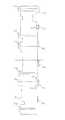
図21に回転筒62の回転角度とレンズ鏡筒2の各移動部材の光軸方向移動距離との関係図を示す。横軸は回転筒62の回転角度であり、縦軸は回転筒62、規制筒63、カム筒65、第2レンズ枠70、第1レンズ枠68の光軸方向への絶対的な移動距離である。各移動部材の移動時の通過ポイントに対応するカム溝の位置(図17、図18、図19)を図21中に示す。図21によりレンズ鏡筒2の各移動部材の光軸方向移動の関係を理解することができる。 FIG. 21 is a relationship diagram between the rotation angle of the
上記の構成により、レンズ鏡筒2の収納位置(カメラ不使用時の位置)では第1レンズ群31と第2レンズ群32とを第3レンズ群33とローパスフィルタ34とCCD35の側方に退避させてレンズ鏡筒2の薄型化を図り、撮影位置では第1レンズ群31と第2レンズ群32とを撮影光軸J1上の所望の位置に移動し、さらにズーミングも可能である構成を実現することができる。 With the above configuration, the
また、第1レンズ群31と第2レンズ群32は、規制筒63より内側の筒状構成部品によって共に支持されているため、光学性能に大きな影響を与える第1レンズ群31と第2レンズ群32とのレンズ光軸の偏心や相対的な傾きを減少させることができるので、撮影位置で光学性能を維持することができる。 In addition, since the
さらに、これらの繰出し機構はズームモータ81を駆動源として回転筒62の回転のみによって行われるため、専用の第1レンズ群31と第2レンズ群の退避機構やその駆動源を別途設ける必要はなく、レンズ鏡筒2の構成が簡素化されて小型化を図ることができる。 Furthermore, since these feeding mechanisms are performed only by the rotation of the
以上本発明の実施形態について説明してきたが、本発明は上記実施形態に限定されるものではなく、様々な変形が可能である。 Although the embodiments of the present invention have been described above, the present invention is not limited to the above embodiments, and various modifications are possible.
例えば、本実施形態では固定筒61に設けた規制筒63のカムフォロア63bが係合するカム溝61bを、回転筒カムフォロアピン64が係合するカム溝61aより深く形成しているが、逆に固定筒61のカム溝61bをカム溝61aより浅く形成しても良い。 For example, in this embodiment, the
また、本実施形態では固定筒61に設けた回転筒カムフォロアピン64が係合するカム溝61aと規制筒63のカムフォロア63bが係合するカム溝61bとは同じカム軌跡を共有する領域61cを持つように形成されているが、図22に示すように固定筒161の回転筒カムフォロアピン64が係合するカム溝161aと規制筒63のカムフォロア63bが係合するカム溝161bとが交差しないように形成されていても良い。固定筒161のカム溝161aとカム溝161bとが交差しなければ、図23に示すように固定筒161の基本厚みD2は本実施の形態での固定筒61の基本厚みD1よりも薄くすることができて外径が小さくなるので、レンズ鏡筒2の小型化を図ることができる。 In the present embodiment, the
また、本実施形態では固定筒61のカム溝61aの61(1)位置から61(4)位置までとカム溝62bの61(12)位置から61(13)位置までとが同一角度をもった直線で形成されており一定量づつ繰出されるように構成されているが、カム溝61aとカム溝61bの軌跡をそれぞれ曲線等で自由に設定して、回転筒62と規制筒63の光軸方向の移動量と中心軸J2まわりの回転量との関係を任意に決めることができる。 In the present embodiment, the
また、本実施形態では回転筒カムフォロアピン64と回転筒62とを別部品で構成しているが、回転筒62にカムフォロア形状を一体に設けても良い。同様に、本実施形態では規制筒63にカムフォロア63bを一体に設けているが、規制筒63とカムフォロア部を別部品で構成しても良い。 Further, in this embodiment, the rotary cylinder
また、固定筒61のカム溝と係合する回転筒カムフォロアピン64および規制筒63のカムフォロア63bは必ずしも3つである必要はなく、1つでも2つでも4つ以上でも良い。 Further, the number of the rotating cylinder cam follower pins 64 and the
また、本実施形態では規制筒63が、カム筒65、直進筒67を介して第1レンズ群31、第2レンズ群32を支持している第1レンズ枠68、第2レンズ枠70を間接的に保持する構成であるが、規制筒63が別の部材を介して撮影光学系を間接的に保持する構成であっても、規制筒63が撮影光学系を直接的に保持する構成であっても良い。 In the present embodiment, the
レンズ鏡筒の光学系は3つのレンズ群により必ずしも構成される必要はなく、1つでも2つでも4つ以上でも良い。規制筒63に保持されて退避させるレンズ群も、第1レンズ群31、第2レンズ群32に限られることなく光学系のうち任意のレンズ群を選択することができる。 The optical system of the lens barrel is not necessarily constituted by three lens groups, and may be one, two, or four or more. The lens group held and retracted by the
また、本実施形態ではズームレンズ鏡筒について本発明のレンズ繰出し機構を適用したものであるが、ズーム動作を行わない鏡筒いわゆる単焦点レンズ鏡筒に対しても適用可能である。単焦点レンズ鏡筒への適用の場合でもズームレンズ鏡筒への適用の場合と同様に収納位置での薄型化を図ることができる。 In the present embodiment, the zoom lens barrel is applied with the lens feeding mechanism of the present invention, but the present invention is also applicable to a so-called single focus lens barrel that does not perform zooming. Even in the case of application to a single focus lens barrel, it is possible to reduce the thickness at the storage position as in the case of application to a zoom lens barrel.
また、本発明のレンズ鏡筒繰出し機構はレンズ鏡筒以外の繰出し機構にも適用が可能である。 The lens barrel feeding mechanism of the present invention can also be applied to feeding mechanisms other than the lens barrel.
レンズ鏡筒の薄型化が図れ携帯性にすぐれたカメラを提供できるので、カメラ分野で利用価値が高い。 Since the lens barrel can be made thinner and a camera with excellent portability can be provided, it is highly useful in the camera field.
1 ボディ本体
2 レンズ鏡筒
3 フォーカス駆動機構
21 CCDホルダ
31 第1レンズ群
32 第2レンズ群
33 第3レンズ群
34 ローパスフィルタ
35 CCD
41 第3レンズ群
44 フォーカスモータ
61 固定筒
62 回転筒
63 規制筒
64 回転筒カムフォロアピン
65 カム筒
66 カム筒ガイド軸
67 直進筒
68 第1レンズ枠
69 第1レンズ枠カムフォロアピン
70 第2レンズ枠
71 シャッタ
81 ズームモータ
83 ズームギア
DESCRIPTION OF
41
Claims (7)
Translated fromJapanese内周面に複数のカム溝が形成され固定された固定筒と、
外周に前記固定筒のカム溝と係合する少なくとも一つのカムフォロアを有し、前記撮影光軸に対して偏心した平行な軸を中心に回転する回転筒と、
外周に前記固定筒のカム溝と係合する少なくとも一つのカムフォロアを有し、前記回転筒に対して回転可能に支持され前方側レンズ群を保持する規制筒と、
前記回転筒に回転力を与え、前記規制筒を前記回転筒の回転軸まわりに回転運動及び前記回転筒の回転軸方向に沿って推進運動させる駆動機構と、を備え、前記回転運動により、前方側レンズ群の中心軸を前記撮影光軸に一致させるように駆動し、前記推進運動により、前方側レンズ群を後方側レンズ群の前方に位置させるように駆動すること、を特徴とするレンズ鏡筒繰出し機構。A lens barrel feeding mechanism that feeds and holds a photographing optical system including a front lens group, a rear lens group, and an imaging device in order from the subject side, and a rear lens group on a photographing optical axis at a storage position; The front lens group is housed in a position away from the photographing optical axis at the side of the imaging device, and at the photographing position, the front lens group is extended, and the photographing optical systemis positioned on the photographing optical axis. In the lens barrel feeding mechanism for feeding and holding
A fixed cylinder in which a plurality of cam grooves are formed and fixed on the inner peripheral surface;
A rotating cylinder having at least one cam follower engaged with a cam groove of the fixed cylinder on an outer periphery, and rotating abouta parallel axisdecentered with respectto thephotographing optical axis ;
At least one cam follower to the cam groove engaging the fixed cylinder to the outer periphery, a regulating tube for holding rotatably supported bythe front side lens group with respect to the rotary cylinder,
Wherein the rotating cylinder gives a rotational force,and a driving mechanism to propel movement along the rotation axis direction of the rotary motion and the rotary cylinder of the regulating cylinder around the rotation shaft of the rotary cylinderby the rotation motion, forward A lens mirror that is driven so that a central axis of the side lens group coincides with the photographing optical axis, and is driven so that the front lens group is positioned in front of the rear lens group by the propulsion movement. Tube feeding mechanism.
収納位置から、収納位置と撮影位置との間の所定位置までは、前記規制筒が前記回転運動をすることなく、前記推進運動のみを行うように、前記固定筒のカム溝が形成されていることを特徴とするレンズ鏡筒繰出し機構。In the lens barrel feeding mechanism according to claim 1,
From the storage position to a predetermined position between the storage position and the photographing position, a cam groove of the fixed cylinder is formedso that the regulating cylinder performs only the propulsion movement without performing the rotational movement . A lens barrel feeding mechanism.
前記固定筒の複数のカム溝は互いに交差しないように形成されていることを特徴とするレンズ鏡筒繰出し機構。In the lens barrel feeding mechanism according to claim 1or 2 ,
A lens barrel feeding mechanism, wherein the plurality of cam grooves of the fixed barrel are formed so as not to cross each other.
前記回転筒のカムフォロアに係合する前記固定筒のカム溝と前記規制筒のカムフォロアに係合する前記固定筒のカム溝とが、同じカム軌跡を共有する領域を持つように配置し、それぞれのカム溝の深さを互いに異なるように形成したことを特徴とするレンズ鏡筒繰出し機構。In the lens barrel feeding mechanism according to claim 1or 2 ,
The cam groove of the fixed cylinder that engages with the cam follower of the rotating cylinder and the cam groove of the fixed cylinder that engages with the cam follower of the restricting cylinder are arranged so as to have an area sharing the same cam locus, A lens barrel feeding mechanism characterized in that cam grooves have different depths.
前記固定筒の浅い方のカム溝に係合するカムフォロアの近傍に、当該カム溝とほぼ係合する形状を有する突起部を設けたことを特徴とするレンズ鏡筒繰出し機構。In the lens barrel feeding mechanism according to claim4 ,
A lens barrel feeding mechanism, characterized in that a protrusion having a shape that substantially engages with the cam groove is provided in the vicinity of the cam follower that engages with the shallower cam groove of the fixed barrel.
前記回転筒の回転によって撮影位置に繰出された撮影光学系が、さらなる回転筒の回転によって焦点距離が可変になるように構成されたことを特徴とするレンズ鏡筒繰出し機構。In the lens barrel feeding mechanism according to any one of claims 1 to5 ,
A lens barrel feeding mechanism, wherein a photographing optical system fed to a photographing position by rotation of the rotating barrel is configured such that a focal length is variable by further rotation of the rotating barrel.
撮影光学系は3つのレンズ群より構成され、規制筒は、前方側レンズ群である、被写体側より1番目のレンズ群と2番目のレンズ群を保持していることを特徴とするレンズ鏡筒繰出し機構。In the lens barrel feeding mechanism according to claim6 ,
The photographing optical system is composed of three lens groups, and the restricting cylinder holdsa first lens group and a second lens group fromthe subject side, which are front lens groups, and a lens barrel characterized by Feeding mechanism.
Priority Applications (6)
| Application Number | Priority Date | Filing Date | Title |
|---|---|---|---|
| JP2004144642AJP4555607B2 (en) | 2004-05-14 | 2004-05-14 | Lens barrel feeding mechanism |
| TW093125760ATWI258025B (en) | 2004-05-14 | 2004-08-27 | Lens barrel extending and retracting mechanism |
| CNB2004100885247ACN100458539C (en) | 2004-05-14 | 2004-11-05 | Lens barrel extending and retracting mechanisms |
| CNU2004201122652UCN2844954Y (en) | 2004-05-14 | 2004-11-05 | Lens cylinder drawing device |
| US11/015,603US7035019B2 (en) | 2004-05-14 | 2004-12-17 | Lens barrel extending and retracting mechanisms |
| HK06105616.7AHK1085804B (en) | 2004-05-14 | 2006-05-16 | Lens barrel draw-out apparatus |
Applications Claiming Priority (1)
| Application Number | Priority Date | Filing Date | Title |
|---|---|---|---|
| JP2004144642AJP4555607B2 (en) | 2004-05-14 | 2004-05-14 | Lens barrel feeding mechanism |
Publications (2)
| Publication Number | Publication Date |
|---|---|
| JP2005326627A JP2005326627A (en) | 2005-11-24 |
| JP4555607B2true JP4555607B2 (en) | 2010-10-06 |
Family
ID=35309141
Family Applications (1)
| Application Number | Title | Priority Date | Filing Date |
|---|---|---|---|
| JP2004144642AExpired - Fee RelatedJP4555607B2 (en) | 2004-05-14 | 2004-05-14 | Lens barrel feeding mechanism |
Country Status (4)
| Country | Link |
|---|---|
| US (1) | US7035019B2 (en) |
| JP (1) | JP4555607B2 (en) |
| CN (2) | CN100458539C (en) |
| TW (1) | TWI258025B (en) |
Families Citing this family (15)
| Publication number | Priority date | Publication date | Assignee | Title |
|---|---|---|---|---|
| JP4555607B2 (en)* | 2004-05-14 | 2010-10-06 | 株式会社オプテック | Lens barrel feeding mechanism |
| JP4645105B2 (en)* | 2004-09-02 | 2011-03-09 | 株式会社ニコン | Retractable camera |
| JP5006576B2 (en)* | 2006-05-26 | 2012-08-22 | 株式会社リコー | Lens barrel, camera using this lens barrel, digital camera, portable information terminal device, and image input device |
| JP2008046503A (en)* | 2006-08-18 | 2008-02-28 | Olympus Imaging Corp | Lens barrel |
| JP4974649B2 (en)* | 2006-11-08 | 2012-07-11 | オリンパスイメージング株式会社 | Lens frame |
| TWI400482B (en)* | 2007-12-31 | 2013-07-01 | Hon Hai Prec Ind Co Ltd | Apparatus and method for disassembling lens module |
| TWI431390B (en)* | 2008-04-30 | 2014-03-21 | Asia Optical Co Inc | Zoom lens |
| JP5446154B2 (en)* | 2008-07-17 | 2014-03-19 | 株式会社ニコン | Lens barrel, optical equipment |
| CN102099739B (en) | 2008-07-17 | 2015-03-25 | 株式会社尼康 | Lens barrels, optical equipment |
| JP5473473B2 (en)* | 2009-08-17 | 2014-04-16 | キヤノン株式会社 | Imaging device |
| CN107219606A (en)* | 2011-07-20 | 2017-09-29 | 株式会社尼康 | Lens barrel and filming apparatus |
| JP6020816B2 (en)* | 2012-01-13 | 2016-11-02 | パナソニックIpマネジメント株式会社 | Lens barrel |
| JP6448186B2 (en)* | 2013-12-11 | 2019-01-09 | キヤノン株式会社 | Lens barrel and optical apparatus equipped with the same |
| JP6316000B2 (en)* | 2014-01-20 | 2018-04-25 | キヤノン株式会社 | Image sensor unit and optical device |
| CN104765220B (en)* | 2015-04-25 | 2017-08-25 | 哈尔滨工业大学 | One kind can open up the telescopic binary optical camera mechanism of receipts based on space |
Family Cites Families (22)
| Publication number | Priority date | Publication date | Assignee | Title |
|---|---|---|---|---|
| US2514239A (en)* | 1948-07-02 | 1950-07-04 | Watson W & Sons Ltd | Variable magnification optical system |
| US2949836A (en)* | 1957-03-14 | 1960-08-23 | Schneider Co Optische Werke | Depth-of-field indicator for photographic objectives |
| US3090282A (en)* | 1959-01-28 | 1963-05-21 | Angenieux Pierre | Mechanism for controlling the axial displacements of optical elements |
| US3329075A (en)* | 1965-03-24 | 1967-07-04 | Graflex Inc | Focusing mechanism for photographic cameras |
| US5812325A (en)* | 1996-01-26 | 1998-09-22 | Asahi Kogaku Kogyo Kabushiki Kaisha | Telescoping-type of zoom lens |
| JPH10282394A (en)* | 1997-04-04 | 1998-10-23 | Fuji Photo Optical Co Ltd | Zoom lens device |
| JP3887081B2 (en)* | 1997-10-01 | 2007-02-28 | ペンタックス株式会社 | Digital still camera |
| JP3598817B2 (en)* | 1998-05-29 | 2004-12-08 | ミノルタ株式会社 | Zoom lens barrel |
| US6264380B1 (en)* | 1999-02-12 | 2001-07-24 | Fuji Photo Optical Co., Ltd. | Barrier opening and closing mechanism |
| JP3495664B2 (en)* | 1999-10-27 | 2004-02-09 | ペンタックス株式会社 | Zoom lens barrel |
| JP3762602B2 (en)* | 2000-02-01 | 2006-04-05 | ペンタックス株式会社 | Lens frame guide device for zoom lens barrel |
| JP2001215391A (en)* | 2000-02-01 | 2001-08-10 | Asahi Optical Co Ltd | Movable hood mechanism for zoom lens barrel |
| JP2003075711A (en)* | 2001-09-06 | 2003-03-12 | Olympus Optical Co Ltd | Zoom lens barrel |
| JP3787298B2 (en)* | 2001-10-31 | 2006-06-21 | ペンタックス株式会社 | Lens barrel |
| TWI229231B (en) | 2002-02-21 | 2005-03-11 | Pentax Corp | Retractable lens system and method of retracting a retractable lens system |
| US6952526B2 (en)* | 2002-08-27 | 2005-10-04 | Pentax Corporation | Retractable lens barrel |
| US6978088B2 (en)* | 2002-08-27 | 2005-12-20 | Pentax Corporation | Optical element retracting mechanism for a retractable lens |
| JP2004085934A (en) | 2002-08-27 | 2004-03-18 | Pentax Corp | Extension cam mechanism and extension cam mechanism for zoom lens barrel |
| US6959148B2 (en)* | 2002-08-27 | 2005-10-25 | Pentax Corporation | Retractable photographing lens |
| JP4181896B2 (en)* | 2003-02-26 | 2008-11-19 | キヤノン株式会社 | Lens barrel and imaging device |
| JP4393107B2 (en)* | 2003-05-15 | 2010-01-06 | 株式会社オプテック | Digital camera |
| JP4555607B2 (en)* | 2004-05-14 | 2010-10-06 | 株式会社オプテック | Lens barrel feeding mechanism |
- 2004
- 2004-05-14JPJP2004144642Apatent/JP4555607B2/ennot_activeExpired - Fee Related
- 2004-08-27TWTW093125760Apatent/TWI258025B/ennot_activeIP Right Cessation
- 2004-11-05CNCNB2004100885247Apatent/CN100458539C/ennot_activeExpired - Fee Related
- 2004-11-05CNCNU2004201122652Upatent/CN2844954Y/ennot_activeExpired - Fee Related
- 2004-12-17USUS11/015,603patent/US7035019B2/ennot_activeExpired - Lifetime
Also Published As
| Publication number | Publication date |
|---|---|
| TWI258025B (en) | 2006-07-11 |
| TW200537159A (en) | 2005-11-16 |
| US20050254144A1 (en) | 2005-11-17 |
| CN100458539C (en) | 2009-02-04 |
| US7035019B2 (en) | 2006-04-25 |
| HK1085804A1 (en) | 2006-09-01 |
| CN2844954Y (en) | 2006-12-06 |
| JP2005326627A (en) | 2005-11-24 |
| CN1696810A (en) | 2005-11-16 |
Similar Documents
| Publication | Publication Date | Title |
|---|---|---|
| JP4969859B2 (en) | Lens barrel | |
| JP4555607B2 (en) | Lens barrel feeding mechanism | |
| JP2005326628A (en) | Lens barrel | |
| JP5011793B2 (en) | Lens barrel and imaging device | |
| JP4969863B2 (en) | Lens barrel | |
| US8351775B2 (en) | Lens barrel and image pickup apparatus | |
| JP5788203B2 (en) | Lens barrel | |
| US7324291B2 (en) | Retractable type lens barrel | |
| JP5172376B2 (en) | Optical device shading structure | |
| JP2013020128A (en) | Lens barrel and imaging apparatus including the same | |
| JP5201475B2 (en) | Lens barrel device and imaging device | |
| JP2009251064A (en) | Lens barrel | |
| JP7059037B2 (en) | Lens barrel and image pickup device | |
| JP4630000B2 (en) | Zoom finder drive mechanism | |
| JP2005326631A (en) | Lens barrel | |
| JP5064271B2 (en) | Lens barrel | |
| JP5201811B2 (en) | Lens barrel and imaging device | |
| US8964306B2 (en) | Lens barrel | |
| JP2012053412A (en) | Lens barrel and imaging apparatus | |
| JP2007101993A (en) | Lens barrel | |
| JP3416317B2 (en) | Lens barrel and optical equipment using the same | |
| JP2017126013A (en) | Lens barrel and imaging device | |
| JP4181784B2 (en) | Zoom lens barrel | |
| JP4808390B2 (en) | Lens barrel and camera | |
| JP2003344745A (en) | Lens barrel |
Legal Events
| Date | Code | Title | Description |
|---|---|---|---|
| A621 | Written request for application examination | Free format text:JAPANESE INTERMEDIATE CODE: A621 Effective date:20070119 | |
| A131 | Notification of reasons for refusal | Free format text:JAPANESE INTERMEDIATE CODE: A131 Effective date:20100107 | |
| A521 | Request for written amendment filed | Free format text:JAPANESE INTERMEDIATE CODE: A523 Effective date:20100406 | |
| RD03 | Notification of appointment of power of attorney | Free format text:JAPANESE INTERMEDIATE CODE: A7423 Effective date:20100406 | |
| TRDD | Decision of grant or rejection written | ||
| A01 | Written decision to grant a patent or to grant a registration (utility model) | Free format text:JAPANESE INTERMEDIATE CODE: A01 Effective date:20100603 | |
| A01 | Written decision to grant a patent or to grant a registration (utility model) | Free format text:JAPANESE INTERMEDIATE CODE: A01 | |
| A601 | Written request for extension of time | Free format text:JAPANESE INTERMEDIATE CODE: A601 Effective date:20100705 | |
| A602 | Written permission of extension of time | Free format text:JAPANESE INTERMEDIATE CODE: A602 Effective date:20100708 | |
| A61 | First payment of annual fees (during grant procedure) | Free format text:JAPANESE INTERMEDIATE CODE: A61 Effective date:20100716 | |
| FPAY | Renewal fee payment (event date is renewal date of database) | Free format text:PAYMENT UNTIL: 20130723 Year of fee payment:3 | |
| R150 | Certificate of patent or registration of utility model | Free format text:JAPANESE INTERMEDIATE CODE: R150 | |
| FPAY | Renewal fee payment (event date is renewal date of database) | Free format text:PAYMENT UNTIL: 20140723 Year of fee payment:4 | |
| R250 | Receipt of annual fees | Free format text:JAPANESE INTERMEDIATE CODE: R250 | |
| LAPS | Cancellation because of no payment of annual fees |