JP4554961B2 - Liquid crystal display device and driving method thereof - Google Patents
Liquid crystal display device and driving method thereofDownload PDFInfo
- Publication number
- JP4554961B2 JP4554961B2JP2004063281AJP2004063281AJP4554961B2JP 4554961 B2JP4554961 B2JP 4554961B2JP 2004063281 AJP2004063281 AJP 2004063281AJP 2004063281 AJP2004063281 AJP 2004063281AJP 4554961 B2JP4554961 B2JP 4554961B2
- Authority
- JP
- Japan
- Prior art keywords
- liquid crystal
- video data
- crystal panel
- line
- signal
- Prior art date
- Legal status (The legal status is an assumption and is not a legal conclusion. Google has not performed a legal analysis and makes no representation as to the accuracy of the status listed.)
- Expired - Fee Related
Links
Images


Classifications
- B—PERFORMING OPERATIONS; TRANSPORTING
- B61—RAILWAYS
- B61L—GUIDING RAILWAY TRAFFIC; ENSURING THE SAFETY OF RAILWAY TRAFFIC
- B61L27/00—Central railway traffic control systems; Trackside control; Communication systems specially adapted therefor
- B61L27/70—Details of trackside communication
- G—PHYSICS
- G09—EDUCATION; CRYPTOGRAPHY; DISPLAY; ADVERTISING; SEALS
- G09G—ARRANGEMENTS OR CIRCUITS FOR CONTROL OF INDICATING DEVICES USING STATIC MEANS TO PRESENT VARIABLE INFORMATION
- G09G3/00—Control arrangements or circuits, of interest only in connection with visual indicators other than cathode-ray tubes
- G09G3/20—Control arrangements or circuits, of interest only in connection with visual indicators other than cathode-ray tubes for presentation of an assembly of a number of characters, e.g. a page, by composing the assembly by combination of individual elements arranged in a matrix no fixed position being assigned to or needed to be assigned to the individual characters or partial characters
- G09G3/34—Control arrangements or circuits, of interest only in connection with visual indicators other than cathode-ray tubes for presentation of an assembly of a number of characters, e.g. a page, by composing the assembly by combination of individual elements arranged in a matrix no fixed position being assigned to or needed to be assigned to the individual characters or partial characters by control of light from an independent source
- G09G3/36—Control arrangements or circuits, of interest only in connection with visual indicators other than cathode-ray tubes for presentation of an assembly of a number of characters, e.g. a page, by composing the assembly by combination of individual elements arranged in a matrix no fixed position being assigned to or needed to be assigned to the individual characters or partial characters by control of light from an independent source using liquid crystals
- G09G3/3611—Control of matrices with row and column drivers
- G09G3/3648—Control of matrices with row and column drivers using an active matrix
- G09G3/3666—Control of matrices with row and column drivers using an active matrix with the matrix divided into sections
- G—PHYSICS
- G09—EDUCATION; CRYPTOGRAPHY; DISPLAY; ADVERTISING; SEALS
- G09G—ARRANGEMENTS OR CIRCUITS FOR CONTROL OF INDICATING DEVICES USING STATIC MEANS TO PRESENT VARIABLE INFORMATION
- G09G3/00—Control arrangements or circuits, of interest only in connection with visual indicators other than cathode-ray tubes
- G09G3/20—Control arrangements or circuits, of interest only in connection with visual indicators other than cathode-ray tubes for presentation of an assembly of a number of characters, e.g. a page, by composing the assembly by combination of individual elements arranged in a matrix no fixed position being assigned to or needed to be assigned to the individual characters or partial characters
- G09G3/34—Control arrangements or circuits, of interest only in connection with visual indicators other than cathode-ray tubes for presentation of an assembly of a number of characters, e.g. a page, by composing the assembly by combination of individual elements arranged in a matrix no fixed position being assigned to or needed to be assigned to the individual characters or partial characters by control of light from an independent source
- G09G3/36—Control arrangements or circuits, of interest only in connection with visual indicators other than cathode-ray tubes for presentation of an assembly of a number of characters, e.g. a page, by composing the assembly by combination of individual elements arranged in a matrix no fixed position being assigned to or needed to be assigned to the individual characters or partial characters by control of light from an independent source using liquid crystals
- G09G3/3611—Control of matrices with row and column drivers
- G09G3/3674—Details of drivers for scan electrodes
- G09G3/3677—Details of drivers for scan electrodes suitable for active matrices only
- B—PERFORMING OPERATIONS; TRANSPORTING
- B61—RAILWAYS
- B61L—GUIDING RAILWAY TRAFFIC; ENSURING THE SAFETY OF RAILWAY TRAFFIC
- B61L2205/00—Communication or navigation systems for railway traffic
Landscapes
- Engineering & Computer Science (AREA)
- Chemical & Material Sciences (AREA)
- Crystallography & Structural Chemistry (AREA)
- Physics & Mathematics (AREA)
- Computer Hardware Design (AREA)
- General Physics & Mathematics (AREA)
- Theoretical Computer Science (AREA)
- Mechanical Engineering (AREA)
- Control Of Indicators Other Than Cathode Ray Tubes (AREA)
- Liquid Crystal (AREA)
- Liquid Crystal Display Device Control (AREA)
Description
Translated fromJapaneseこの発明は、ドレイン線が共通の複数の液晶パネルを用いて、同時に異なる画像の表示を行うことを可能にした、液晶表示装置およびその駆動方法に関する。 The present invention relates to a liquid crystal display device and a driving method thereof, which can simultaneously display different images using a plurality of liquid crystal panels having a common drain line.
従来、1枚の液晶表示パネルによって、複数の異なる画像を表示する液晶表示装置については、例えば特許文献1に開示されたようなものがある。
この従来例の液晶表示装置は、1枚の液晶表示パネルの表示領域を2つに分けて、それぞれを例えば表面表示領域,裏面表示領域として、1枚の液晶表示パネルの表裏両面に表示可能にしたものであって、液晶ドライバICからの配線の一部または全部を表面表示領域用と裏面表示領域用とに共用することによって、ドライバICが表裏両面に表示できる画素数を増加させた構成と駆動方法とを提案している。Conventionally, for example, a liquid crystal display device that displays a plurality of different images with a single liquid crystal display panel is disclosed in
In this conventional liquid crystal display device, the display area of one liquid crystal display panel is divided into two, and each can be displayed on both the front and back surfaces of one liquid crystal display panel, for example, as a front display area and a back display area. And a configuration in which the number of pixels that the driver IC can display on both the front and back surfaces is increased by sharing part or all of the wiring from the liquid crystal driver IC for the front surface display region and the rear surface display region. A drive method is proposed.
また、特許文献2においては、複数の液晶パネルに対して、液晶駆動用LSIを含む周辺回路を共用して、部品点数の削減と機器の小型化・薄型化を可能にした液晶表示装置が開示されている。
また、特許文献3においては、表側表示パネルと裏側表示パネルを有する表示媒体において、表側表示パネルと裏側表示パネルにそれぞれ信号電極と走査電極を設けて、表側表示パネルの信号電極と裏側表示パネルの信号電極を、それぞれ同一の信号電極駆動ICに電気的に接続することによって、駆動IC数を減らして小型化・簡易化した両面表示媒体を形成することが記載されている。Further,
Further, in
また、特許文献4においては、2枚の液晶パネル間にドライバICを挟持することによって、両面表示時の部品点数および実装工程を削減した電気光学装置が開示されている。
さらに、特許文献5においては、2枚の液晶表示素子を共通の照射手段によって照射するとともに、共通の駆動用ICによって駆動することによって、使用部品数を削減した表裏同時表示形式の液晶表示装置が開示されている。
Further, in
特許文献1に記載された従来技術では、コモン配線またはセグメント配線を、表面の表示領域と裏面の表示領域ににおいてそれぞれ独立に制御することができない。そのため、正常に表示できるのは、表面の表示領域または裏面の表示領域のいずれか一方だけであって、同時に表裏両面の表示領域に正常表示を行うことはできない。
また、この従来技術では、コモン配線またはセグメント配線のどちらか一方のみを共有する構成についても記述されているが、同時に表裏両面の表示領域を利用者が見ることを想定していないため、表面の表示領域と裏面の表示領域とを同時に正常表示することを可能にする駆動方法については提案されていない。In the prior art described in
In addition, this conventional technology describes a configuration in which only one of the common wiring and the segment wiring is shared. However, since it is not assumed that the user views the display areas on both the front and back sides at the same time, No driving method has been proposed that enables normal display of the display area and the display area on the back side simultaneously.
また、特許文献3に記載された従来技術では、両面表示媒体において、表側表示パネルと裏側表示パネルにそれぞれ信号電極と走査電極を設けて、表側表示パネルの信号電極と裏側表示パネルの信号電極と同一の信号電極駆動ICから駆動することが記載されているが、ドレイン線が共通の複数の液晶パネルに対して、同時に異なる画像の表示を行うことについては記載されていない。
なお、これ以外の上記した各特許文献においても、ドレイン線が共通な構成を有する複数の液晶パネルにおいて、同時に異なる画像の表示を可能にすることについては記載されていない。
このように従来の液晶表示装置においては、ドレイン線を共有する複数の液晶パネルを用いて、複数の液晶パネルを同時に見た場合において、異なる内容の表示を行うことはできなかった。In the prior art described in
In each of the above-mentioned patent documents other than this, it is not described that a plurality of liquid crystal panels having a common drain line can simultaneously display different images.
As described above, in the conventional liquid crystal display device, when a plurality of liquid crystal panels are viewed at the same time using a plurality of liquid crystal panels sharing the drain line, different contents cannot be displayed.
この発明は上述の事情に鑑みてなされたものであって、ドレイン線が共通の複数の液晶パネルを用いて、同時に異なる画像の表示を行うことを可能にした、液晶表示装置およびその駆動方法を提供することを目的としている。 The present invention has been made in view of the above-described circumstances, and provides a liquid crystal display device and a driving method thereof capable of simultaneously displaying different images using a plurality of liquid crystal panels having a common drain line. It is intended to provide.
上記課題を解決するため、請求項1記載の発明は液晶表示装置に係り、ドレイン線を共有する複数の液晶パネルと、前記複数の液晶パネルに対応する複数の映像データ信号の出力タイミングを制御するタイミングコントローラ手段と、前記タイミングコントローラ手段からの出力タイミング制御に応じて、前記複数の液晶パネルの複数のドレイン線にラインごとに映像データを出力するソースドライバ手段と、前記タイミングコントローラ手段からの前記各液晶パネルに対する映像データ信号の出力開始を指示する信号と、前記各映像データ信号を構成するラインごとの映像データの入力周期を制御する信号との入力に応じて、対応する液晶パネルの複数のゲート線に順次ゲート駆動パルスを出力する、前記各液晶パネルに対応して設けられた複数のゲートドライバ手段とを備え、前記タイミングコントローラ手段が、前記ソースドライバ手段と前記複数のゲートドライバ手段とを制御して、書き込み先の液晶パネルをライン周期で順次切り換えてラインごとの前記映像データを前記ドレイン線に出力して対応する液晶パネルに書き込むことを特徴としている。In order to solve the above-mentioned problem, the invention according to
また、請求項2記載の発明は液晶表示装置に係り、ドレイン線を共有する複数の液晶パネルと、前記複数の液晶パネルに対応する複数の映像データ信号の出力タイミングを制御するタイミングコントローラ手段と、前記タイミングコントローラ手段からの出力タイミング制御に応じて、前記複数の液晶パネルの複数のドレイン線にラインごとに映像データを出力するソースドライバ手段と、前記タイミングコントローラ手段からの前記各液晶パネルに対する映像データ信号の出力開始を指示する信号と、前記各映像データ信号を構成するラインごとの映像データの入力周期を制御する信号と、前記映像データ信号を出力する液晶パネルを指定する信号との入力に応じて、指定された液晶パネルごとにそれぞれの複数のゲート線に順次ゲート駆動パルスを出力する、前記各液晶パネルに共通に設けられたゲートドライバ手段とを備え、前記タイミングコントローラ手段が、前記ソースドライバ手段と前記複数のゲートドライバ手段とを制御して、書き込み先の液晶パネルをライン周期で順次切り換えてラインごとの前記映像データを前記ドレイン線に出力して対応する液晶パネルに書き込むことを特徴としている。The invention according to
また、請求項3記載の発明は、液晶表示装置の駆動方法に係り、ドレイン線を共有する複数の液晶パネルと、前記複数の液晶パネルに対応する複数の映像データ信号の出力タイミングを制御するタイミングコントローラ手段と、前記タイミングコントローラ手段からの出力タイミング制御に応じて、前記複数の液晶パネルの複数のドレイン線にラインごとに映像データを出力するソースドライバ手段と、前記タイミングコントローラ手段からの前記各液晶パネルに対する映像データ信号の出力開始を指示する信号と、前記各映像データ信号を構成するラインごとの映像データの入力周期を制御する信号との入力に応じて、対応する液晶パネルの複数のゲート線に順次ゲート駆動パルスを出力する、前記各液晶パネルに対応して設けられた複数のゲートドライバ手段とを備えてなる液晶表示装置において、前記タイミングコントローラ手段に、前記ソースドライバ手段と前記複数のゲートドライバ手段とを制御させて、書き込み先の液晶パネルをライン周期で順次切り換えさせてラインごとの前記映像データを前記ドレイン線に出力して対応する液晶パネルに書き込ませることを特徴としている。According to a third aspect of the present invention, there is provided adriving method of a liquid crystal display device, wherein a plurality of liquid crystal panels sharing drain lines and atiming for controlling output timings of a plurality of video data signals corresponding to the plurality of liquid crystal panels. Controller means; source driver means for outputting video data line by line to a plurality of drain lines of the plurality of liquid crystal panels according to output timing control from the timing controller means; and the liquid crystals from the timing controller means A plurality of gate lines of the corresponding liquid crystal panel in response to an input of a signal instructing start of output of the video data signal to the panel and a signal for controlling an input period of the video data for each line constituting each video data signal A plurality of gate driving pulses are sequentially output to each of the liquid crystal panels. In the liquid crystal display device comprising the gate driver means, the timing controller means controls the source driver means and the plurality of gate driver means, and sequentially switches the liquid crystal panel to be written in a line cycle. Each video data is output to the drain line and written to a corresponding liquid crystal panel .
また、請求項4記載の発明は、液晶表示装置の駆動方法に係り、ドレイン線を共有する複数の液晶パネルと、前記複数の液晶パネルに対応する複数の映像データ信号の出力タイミングを制御するタイミングコントローラ手段と、前記タイミングコントローラ手段からの出力タイミング制御に応じて、前記複数の液晶パネルの複数のドレイン線にラインごとに映像データを出力するソースドライバ手段と、前記タイミングコントローラ手段からの前記各液晶パネルに対する映像データ信号の出力開始を指示する信号と、前記各映像データ信号を構成するラインごとの映像データの入力周期を制御する信号と、前記映像データ信号を出力する液晶パネルを指定する信号との入力に応じて、指定された液晶パネルごとにそれぞれの複数のゲート線に順次ゲート駆動パルスを出力する、前記各液晶パネルに共通に設けられたゲートドライバ手段とを備えてなる液晶表示装置において、前記タイミングコントローラ手段に、前記ソースドライバ手段と前記複数のゲートドライバ手段とを制御させて、書き込み先の液晶パネルをライン周期で順次切り換えさせてラインごとの前記映像データを前記ドレイン線に出力して対応する液晶パネルに書き込ませることを特徴としている。According to a fourth aspect of the present invention, there is provided a driving method of a liquid crystal display device, wherein a plurality of liquid crystal panels sharing drain lines and atiming for controlling output timings of a plurality of video data signals corresponding to the plurality of liquid crystal panels. Controller means; source driver means for outputting video data line by line to a plurality of drain lines of the plurality of liquid crystal panels according to output timing control from the timing controller means; and the liquid crystals from the timing controller means A signal for instructing output start of the video data signal to the panel, a signal for controlling an input period of video data for each line constituting each video data signal, and a signal for designating a liquid crystal panel for outputting the video data signal Depending on the input of the In a liquid crystal display device comprising a gate driver means provided in common to each of the liquid crystal panels for outputting a next gate drive pulse, the timing controller means includes the source driver means and the plurality of gate driver means. The liquid crystal panel to which data is written is sequentially switched in a line cycle, and the video data for each line is output to the drain line and written to the corresponding liquid crystal panel .
本発明の液晶表示装置およびその駆動方法によれば、ドレイン線を共有する構成の複数の液晶パネルを用いて、複数の液晶パネルを同時に見た場合においても、それぞれの液晶パネルにおいて異なる内容の表示を行うことが可能な、液晶表示装置を実現することができる。 According to the liquid crystal display device and the driving method of the present invention, even when a plurality of liquid crystal panels are viewed at the same time using a plurality of liquid crystal panels configured to share drain lines, different contents are displayed on the respective liquid crystal panels. A liquid crystal display device capable of performing the above can be realized.
ドレイン線を共有する複数の液晶パネルを備えた液晶表示装置において、複数の液晶パネルに対応する複数の映像データ信号の出力タイミングを制御するタイミングコントローラ手段と、タイミングコントローラ手段からの出力タイミング制御に応じて、複数の液晶パネルの複数のドレイン線にラインごとに映像データを出力するソースドライバ手段と、タイミングコントローラ手段からの各液晶パネルに対する映像データ信号の出力開始を指示する信号と、各映像データ信号を構成するラインごとの映像データの入力周期を制御する信号との入力に応じて、対応する液晶パネルの複数のゲート線に順次ゲート駆動パルスを出力する、各液晶パネルに対応して設けられた複数のゲートドライバ手段とを備えて、複数の映像データ信号を構成する複数のラインごとの映像データを入力順に、映像データ信号ごとに順次切り換えて対応する液晶パネルのドレイン線に出力する。 In a liquid crystal display device having a plurality of liquid crystal panels sharing a drain line, timing controller means for controlling the output timing of a plurality of video data signals corresponding to the plurality of liquid crystal panels, and according to output timing control from the timing controller means Source driver means for outputting video data line by line to a plurality of drain lines of a plurality of liquid crystal panels, a signal for instructing start of output of a video data signal to each liquid crystal panel from the timing controller means, and each video data signal Provided in correspondence with each liquid crystal panel, which sequentially outputs gate drive pulses to a plurality of gate lines of the corresponding liquid crystal panel in response to an input with a signal for controlling the input cycle of video data for each line constituting A plurality of gate driver means to form a plurality of video data signals. The video data for a plurality of lines in the input order, and outputs to the drain line of the corresponding liquid crystal panels sequentially switched to each video data signal.
図1は、本発明の第1実施例である液晶表示装置の構成を示す図、図2は、本実施例の液晶表示装置の動作を説明するためのタイミングチャートである。
この例の液晶表示装置は、図1に示すように、タイミングコントローラ1と、ソースドライバ2と、第1の液晶パネル3と、ドレイン線4と、第1のゲート線5と、第2のゲート線6と、第1のゲートドライバ7と、第2の液晶パネル8と、第2のゲートドライバ9とから概略構成されている。FIG. 1 is a diagram showing a configuration of a liquid crystal display device according to a first embodiment of the present invention, and FIG. 2 is a timing chart for explaining the operation of the liquid crystal display device according to the present embodiment.
As shown in FIG. 1, the liquid crystal display device of this example includes a
タイミングコントローラ1には、第1の液晶パネル3において表示を行うための映像データ信号ADIと第2の液晶パネル8において表示を行うための映像データ信号BDI、およびデータイネーブル信号DE等の同期信号が入力される。
タイミングコントローラ1は、これらの入力信号からソースドライバ2の制御信号として、映像データ信号DO,スタートパルス信号STH,シフトクロック信号HCKおよびデータラッチ信号STBを出力する。
また、タイミングコントローラ1は、ゲートドライバ7の制御信号として、スタートパルス信号STVA,シフトクロック信号VCKAを出力し、ゲートドライバ9の制御信号として、スタートパルス信号STVB,シフトクロック信号VCKBを出力する。The
The
The
この例の映像表示装置においては、タイミングコントローラ1が映像データ信号ADIと映像データ信号BDIを、ライン周期で交互にドレイン線4に出力するように映像データ信号DOを制御し、そのタイミングに合わせて第1のゲートドライバ7と第2のゲートドライバ9を制御することによって、ドレイン線を共有する第1の液晶パネル3と第2の液晶パネル8において、同時に観察した場合でも異なる内容の表示を行うことができる。 In the video display device of this example, the
以下、図2を参照して、この例の液晶表示装置の動作を説明する。
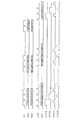
図2においては、解像度(1024×768)の2枚の液晶パネルにおいて表示を行う際のタイミングを例として、この例の液晶表示装置の動作を示している。
図中、データイネーブル信号DEは、 "L”期間がINVALID期間を表し、 "H”期間がVALID期間を表すものとする。
映像データ信号ADIは、第1の液晶パネル3において表示を行うべき信号であり、AD0が1ライン目の映像データを、AD1が2ライン目の映像データを、AD3が3ライン目の映像データを示し、以下、同様にしてAD767が768ライン目の映像データをそれぞれ示している。
また、映像データ信号BDIは、第2の液晶パネル8において表示を行うべき信号であり、BD0が1ライン目の映像データを、BD1が2ライン目の映像データを、BD3が3ライン目の映像データを示し、以下、同様にしてBD767が768ライン目の映像データをそれぞれ示している。The operation of the liquid crystal display device of this example will be described below with reference to FIG.
FIG. 2 shows the operation of the liquid crystal display device of this example, taking as an example the timing when display is performed on two liquid crystal panels having a resolution (1024 × 768).
In the figure, in the data enable signal DE, the “L” period represents the INVALID period, and the “H” period represents the VALID period.
The video data signal ADI is a signal to be displayed on the first
The video data signal BDI is a signal to be displayed on the second
この第1の液晶パネル3のための映像データAD0〜AD767と第2の液晶パネル8のための映像データBD0〜BD767が交互に出力されるように、タイミングコントローラ1によって映像データ信号DOを制御する。
ソースドライバ2は、入力された映像データ信号DOによって、AD0→BD0→AD1→BD1→,…,→AD766→BD766→AD767→BD767の順に、ドレイン線4に映像データを出力する。The video data signal DO is controlled by the
The
タイミングコントローラ1は、ソースドライバ2からドレイン線4に出力されるラインごとの映像データAD0→BD0→AD1→BD1→,…,→AD766→BD766→AD767→BD767が、第1の液晶パネル3と第2の液晶パネル8においてそれぞれ正しく表示されるために、映像データAD0が先頭データになるように、スタートパルス信号STVAを生成するとともに、映像データBD0が先頭データになるように、スタートパルス信号STVBを生成し、また、スタートパルス信号STVAに合わせてシフトクロック信号VCKAを2ライン周期で生成するとともに、スタートパルス信号STVBに合わせてシフトクロック信号VCKBを2ライン周期で生成する。 In the
そして、第1のゲートドライバ7に入力されたスタートパルス信号STVAとシフトクロック信号VCKA、および第2のゲートドライバ9に入力されたスタートパルス信号STVBとシフトクロック信号VCKBによって、ゲート線5とゲート線6にゲート駆動パルスを交互に出力する。
このような制御を行うことによって、第1の液晶パネル3と第2の液晶パネル8は、ソースドライバ2とドレイン線4とを共用して、それぞれの液晶パネルにおいて同時に異なる表示を行うことができる。Then, the
By performing such control, the first
このように、この例の液晶表示装置においては、第1の液晶パネル3と第2の液晶パネル8において、ソースドライバ2とドレイン線4とを共用する構成でありながら、それぞれの液晶パネルにおいて、同時に異なる表示を行うことが可能である。 As described above, in the liquid crystal display device of this example, the first
図3は、本発明の第2実施例である液晶表示装置の構成を示す図、図4は、本実施例の液晶表示装置の動作を説明するためのタイミングチャートである。
図1,図2に示された第1実施例においては、1ライン周期で交互に第1の液晶パネル3と第2の液晶パネル8とに映像データを書き込む駆動方法をとっているが、以下においては、フレーム周期で交互に第1の液晶パネル3と第2の液晶パネル8とに映像データを書き込む駆動方法をとる場合を第2実施例として説明する。
この例の液晶表示装置は、図3に示すように、タイミングコントローラ1Aと、ソースドライバ2と、第1の液晶パネル3と、ドレイン線4と、第1のゲート線5と、第2のゲート線6と、第1のゲートドライバ7Aと、第2の液晶パネル8と、第2のゲートドライバ9Aとから概略構成されている。
これらのうち、ソースドライバ2,第1の液晶パネル3,ドレイン線4,第1のゲート線5,第2のゲート線6,第2の液晶パネル8は、図1に示された第1実施例の場合と同様である。FIG. 3 is a diagram showing the configuration of the liquid crystal display device according to the second embodiment of the present invention, and FIG. 4 is a timing chart for explaining the operation of the liquid crystal display device of this embodiment.
In the first embodiment shown in FIG. 1 and FIG. 2, a driving method for writing video data to the first
As shown in FIG. 3, the liquid crystal display device of this example includes a
Among these, the
第1のゲートドライバ7Aと第2のゲートドライバ9Aとは、カスケード接続されるように構成されている。タイミングコントローラ1Aには、第1の液晶パネル3において表示を行うための映像データ信号ADIと第2の液晶パネル8において表示を行うための映像データ信号BDI、およびデータイネーブル信号DE等の同期信号が入力され、タイミングコントローラ1Aは、これらの入力信号から、ソースドライバ2の制御信号として、映像データ信号DO,スタートパルス信号STH,シフトクロック信号HCKおよびデータラッチ信号STBを出力するとともに、第1のゲートドライバ7Aと第2のゲートドライバ9Aの制御信号として、スタートパルス信号STVとシフトクロック信号VCKを出力する。スタートパルス信号STVは、第1のゲートドレイン7Aと第2のゲートドレイン9Aとにカスケードに与えられる。 The
このように構成することによって、映像データ信号DOが映像データ信号ADI,映像データ信号BDIとしてフレーム周期で連続して交互にドレイン線4に出力されるように制御し、そのタイミングに合わせて、第1のゲートドライバ7Aと第2のゲートドライバ9Aとを制御することによって、ドレイン線を共有する第1の液晶パネル3と第2の液晶パネル8とを同時に観察した場合でも、異なる内容の表示を行うことができる。 With this configuration, the video data signal DO is controlled so as to be alternately output to the
以下、図4を参照して、この例の液晶表示装置の動作を説明する。
図4においては、解像度(1024×768)の2枚の液晶パネルにおいて表示を行う際のタイミングを例として、この例の液晶表示装置の動作を示している。
タイミングコントローラ1Aは、図4に示すように、第1の液晶パネル3に対する映像データAD0〜AD767と、第2の液晶パネル8に対する映像データBD0〜BD767が連続して出力されるように、映像データ信号DOを制御する。
ソースドライバ2は、入力された映像データ信号DOによって、映像データAD0→AD1→,…,→AD767→BD0→BD1→,…,→BD767の順に、ドレイン線4に映像データを出力する。The operation of the liquid crystal display device of this example will be described below with reference to FIG.
FIG. 4 shows the operation of the liquid crystal display device of this example, taking as an example the timing when display is performed on two liquid crystal panels having a resolution (1024 × 768).
As shown in FIG. 4, the
The
タイミングコントローラ1は、ソースドライバ2からドレイン線4に出力されるフレームごとの映像データAD0→AD1→,…,→AD767→BD0→BD1→,…,→AD767が、第1の液晶パネル3と第2の液晶パネル8においてそれぞれ正しく表示されるように、映像データAD0が第1の液晶パネル3に表示されるデータの先頭になるようにスタートパルス信号STVAを生成し、映像データBD0が第2の液晶パネル8に表示されるデータの先頭になるようにスタートパルス信号STVBを生成するとともに、シフトクロック信号VCKを1ライン周期で生成する。 In the
そして、第1のゲートドライバ7Aに入力されたスタートパルス信号STVとシフトクロック信号VCK、および第1のゲートドライバ7Aから第2のゲートドライバ9Aにカスケードに入力されたスタートパルス信号STVとシフトクロック信号VCKによって、ゲート線5にゲート駆動パルスが出力されたのち、ゲート線6にゲート駆動パルスが出力される。
このような制御を行うことによって、第1の液晶パネル3と第2の液晶パネル8は、ソースドライバ2とドレイン線4を共用して、それぞれの液晶パネルにおいて同時に異なる表示を行うことができる。The start pulse signal STV and shift clock signal VCK input to the
By performing such control, the first
このように、この例の液晶表示装置においては、第1の液晶パネル3と第2の液晶パネル8において、ソースドライバ2とドレイン線4を共用する構成でありながら、それぞれの液晶パネルにおいて、同時に異なる表示を行うことが可能である。 As described above, in the liquid crystal display device of this example, the first
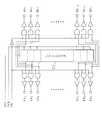
図5は、本発明の第3実施例である液晶表示装置の構成を示す図、図6は、本実施例におけるゲートドライバの構成を示す図、図7は、本実施例の液晶表示装置の動作を説明するためのタイミングチャートである。
図1,図2に示された第1実施例、および図3,図4に示された第2実施例においては、第1の液晶パネル3と第2の液晶パネル8に対して、それぞれゲートドライバを備えるように構成されているが、以下においては、第1の液晶パネル3と第2の液晶パネル8に対して共通のゲートドライバを備える場合を第3実施例として説明する。
この例の液晶表示装置は、図5に示すように、タイミングコントローラ1Bと、ソースドライバ2と、第1の液晶パネル3と、ドレイン線4と、ゲート線5と、ゲート線6と、第2の液晶パネル8と、ゲートドライバ10とから概略構成されている。
これらのうち、ソースドライバ2,第1の液晶パネル3,ドレイン線4,ゲート線5,ゲート線6,第2の液晶パネル8は、図1に示された第1実施例の場合と同様である。ゲートドライバ10は、ゲート線5とゲート線6の双方を駆動可能なゲートドライバである。5 is a diagram showing a configuration of a liquid crystal display device according to a third embodiment of the present invention, FIG. 6 is a diagram showing a configuration of a gate driver in this embodiment, and FIG. 7 is a diagram of a liquid crystal display device according to the present embodiment. It is a timing chart for explaining operation.
In the first embodiment shown in FIGS. 1 and 2, and in the second embodiment shown in FIGS. 3 and 4, gates are provided for the first
As shown in FIG. 5, the liquid crystal display device of this example includes a
Among these, the
タイミングコントローラ1Bには、第1の液晶パネル3において表示を行うための映像データ信号ADIと第2の液晶パネル8において表示を行うための映像データ信号BDI、およびデータイネーブル信号DE等の同期信号が入力され、タイミングコントローラ1Bはこれらの入力信号から、ソースドライバ2の制御信号として、映像データ信号DO,スタートパルス信号STH,シフトクロック信号HCKおよびデータラッチ信号STBを出力するとともに、ゲートドライバ10に対する制御信号として、スタートパルス信号STV,シフトクロック信号VCKおよび出力イネーブル信号OEを出力する。 The
ゲートドライバ10は、図6に示すように、スタートパルス信号STVとシフトクロック信号VCKとから、シフトレジスタ71を共用して、第1の液晶パネル3と第2の液晶パネル8に対して左右双方に、ゲート駆動パルスLX1,LX2,…,LXn-1,LXnと、ゲート駆動パルスRX1,RX2,…,RXn-1,RXn(nは、ゲート線5,ゲート線6の数)を出力可能であり、出力イネーブル信号OEに応じて左右どちらに出力するかを制御できるように構成されている。As shown in FIG. 6, the
この例の液晶表示装置においては、ソースドライバ2に入力される映像データ信号DOによって、映像データ信号ADIと映像データ信号BDIを1ライン周期で交互にドレイン線4に出力するようにソースドライバ2を制御し、そのタイミングに合わせてゲートドライバ10を制御することによって、ドレイン線4を共有する第1の液晶パネル3と第2の液晶パネル8を同時に観察した場合においても、異なる内容を表示することが可能になる。 In the liquid crystal display device of this example, the
以下、図7を参照して、この例の液晶表示装置の動作を説明する。
図7においては、解像度(1024×768)の2枚の液晶パネルにおいて表示を行う際のタイミングを例として、この例の液晶表示装置の動作を示している。
タイミングコントローラ1Bは、図7に示すように、第1の液晶パネル3に対する映像データAD0〜AD767と、第2の液晶パネル8に対する映像データBD0〜BD767が、1ラインごとに交互に出力されるように、映像データ信号DOを制御する。
ソースドライバ2は、入力された映像データ信号DOによって、映像データAD0→BD0→AD1→BD1→,…,→AD766→BD766→AD767→BD767の順に、ドレイン線4に映像データを出力する。The operation of the liquid crystal display device of this example will be described below with reference to FIG.
FIG. 7 shows the operation of the liquid crystal display device of this example, taking as an example the timing when display is performed on two liquid crystal panels having a resolution (1024 × 768).
As shown in FIG. 7, the
The
ソースドライバ2からドレイン線4に出力されたラインごとの映像データAD0→BD0→AD1→BD1→,…,→AD766→BD766→AD767→BD767が、第1の液晶パネル3と第2の液晶パネル8にそれぞれ正しく表示されるように、シフトクロック信号VCKを2ライン周期で生成し、1ライン周期で出力イネーブル信号OEの論理を反転するように制御する。
そして、ゲートドライバ10に入力されたシフトクロック信号VCKと出力イネーブル信号OEによって、図6に示されたゲートドライバ10が、出力イネーブル信号OEに応じて、ゲート駆動パルスを、LX1→RX1→LX2→RX2→,…,→LXn-1→RXn-1→LXn→RXnの順に、ゲート線5,ゲート線6に出力する。
このような制御を行うことによって、第1の液晶パネル3と第2の液晶パネル8は、ソースドライバ2とドレイン線4を共用して、それぞれの液晶パネルにおいて同時に異なる表示を行うことができる。The video data AD0 → BD0 → AD1 → BD1 →,... → AD766 → BD766 → AD767 → BD767 output from the
Then, the shift clock signal VCK and the output enable signal OE input to the
By performing such control, the first
このように、この例の液晶表示装置においては、第1の液晶パネル3と第2の液晶パネル8において、ソースドライバ2とドレイン線4とを共用する構成でありながら、それぞれの液晶パネルにおいて、同時に異なる表示を行うことが可能である。 As described above, in the liquid crystal display device of this example, the first
図8は、本発明の第4実施例である液晶表示装置の動作を説明するためのタイミングチャートである。
この例の液晶表示装置の構成とゲートドライバの構成は、図5,図6に示された第3実施例の場合と同様であるが、フレーム周期で第1の液晶パネル3と第2の液晶パネル8に交互に書き込みを行う点が第3実施例の場合と異なっている。FIG. 8 is a timing chart for explaining the operation of the liquid crystal display device according to the fourth embodiment of the present invention.
The configuration of the liquid crystal display device of this example and the configuration of the gate driver are the same as those of the third embodiment shown in FIGS. 5 and 6, but the first
以下、図8を参照して、この例の液晶表示装置の動作を説明する。
図8においては、解像度(1024×768)の2枚の液晶パネルにおいて表示を行う際のタイミングを例として、この例の液晶表示装置の動作を示している。
図8に示すように、第1の液晶パネル3に対する映像データAD0〜AD767と、第2の液晶パネル8に対する映像データBD0〜BD767が連続して出力されるように、映像データ信号DOを制御する。
ソースドライバ2は、入力された映像データ信号DOによって、映像データAD0→AD1→,…,→AD766→AD767→BD0→BD1→,…,→BD766→BD767の順に、ドレイン線4に映像データを出力する。Hereinafter, the operation of the liquid crystal display device of this example will be described with reference to FIG.
FIG. 8 shows the operation of the liquid crystal display device of this example, taking as an example the timing when display is performed on two liquid crystal panels having a resolution (1024 × 768).
As shown in FIG. 8, the video data signal DO is controlled so that the video data AD0 to AD767 for the first
The
ソースドライバ2からドレイン線4に出力されたフレームごとの映像データAD0→AD1→,…,→AD766→AD767→BD0→BD1,→,BD766→BD767が、第1の液晶パネル3と第2の液晶パネル8にそれぞれ正しく表示されるように、1フレーム周期で出力イネーブル信号OEの論理を反転するように制御する。
そして、ゲートドライバ10に入力された出力イネーブル信号OEに応じて、ゲート駆動パルスを、LX1→LX2→,…,→LXn-1→LXn→RX1→RX2→,…,→RXn-1→RXnの順に、ゲート線5,ゲート線6に出力する。
このような制御を行うことによって、第1の液晶パネル3と第2の液晶パネル8は、ソースドライバ2とドレイン線4とを共用して、それぞれの液晶パネルにおいて同時に異なる表示を行うことができる。The video data AD0 → AD1 →,... → AD766 → AD767 → BD0 → BD1, →, BD766 → BD767 output from the
Then, in accordance with the output enable signal OE input to the
By performing such control, the first
このように、この例の液晶表示装置においては、第1の液晶パネル3と第2の液晶パネル8において、ソースドライバ2とドレイン線4とを共用する構成でありながら、それぞれの液晶パネルにおいて、同時に異なる表示を行うことが可能である。 Thus, in the liquid crystal display device of this example, the
以上、この発明の実施例を図面により詳述してきたが、具体的な構成はこの実施例に限られたものではなく、この発明の要旨を逸脱しない範囲の設計の変更等があってもこの発明に含まれる。例えば、各実施例において、液晶パネル3,液晶パネル8の解像度は、1024×768の場合に限らず、他の解像度、例えば、1280×1024、1280×768等であってもよい。 The embodiment of the present invention has been described in detail with reference to the drawings. However, the specific configuration is not limited to this embodiment, and even if there is a design change or the like without departing from the gist of the present invention. Included in the invention. For example, in each embodiment, the resolution of the
本発明の液晶表示装置は、表裏同時表示形式の携帯電話機に適用して好適なものであるが、この場合に限らず、表示部を複数有する表裏同時表示方式の各種携帯用情報機器等においても、広く利用することが可能なものである。 The liquid crystal display device of the present invention is suitable for application to a front-and-back simultaneous display type mobile phone, but is not limited to this case, and is also applicable to various portable information devices and the like of a front-and-back simultaneous display system having a plurality of display units. Can be widely used.
1,1A,1B タイミングコントローラ(タイミングコントローラ手段)
2 ソースドライバ(ソースドライバ手段)
3 第1の液晶パネル(液晶パネル)
4 ドレイン線
5 第1のゲート線
6 第2のゲート線
7,7A 第1のゲートドライバ(ゲートドライバ手段)
8 第2の液晶パネル(液晶パネル)
9,9A 第2のゲートドライバ(ゲートドライバ手段)
10 ゲートドライバ(ゲートドライバ手段)
71 シフトレジスタ1,1A, 1B Timing controller (timing controller means)
2 Source driver (source driver means)
3 First liquid crystal panel (liquid crystal panel)
4
8 Second liquid crystal panel (liquid crystal panel)
9, 9A Second gate driver (gate driver means)
10 Gate driver (gate driver means)
71 Shift register
Claims (4)
Translated fromJapanese前記複数の液晶パネルに対応する複数の映像データ信号の出力タイミングを制御するタイミングコントローラ手段と、
前記タイミングコントローラ手段からの出力タイミング制御に応じて、前記複数の液晶パネルの複数のドレイン線にラインごとに映像データを出力するソースドライバ手段と、
前記タイミングコントローラ手段からの前記各液晶パネルに対する映像データ信号の出力開始を指示する信号と、前記各映像データ信号を構成するラインごとの映像データの入力周期を制御する信号との入力に応じて、対応する液晶パネルの複数のゲート線に順次ゲート駆動パルスを出力する、前記各液晶パネルに対応して設けられた複数のゲートドライバ手段とを備え、
前記タイミングコントローラ手段は、前記ソースドライバ手段と前記複数のゲートドライバ手段とを制御して、書き込み先の液晶パネルをライン周期で順次切り換えてラインごとの前記映像データを前記ドレイン線に出力して対応する液晶パネルに書き込むことを特徴とする液晶表示装置。A plurality of liquid crystal panels sharing drain lines;
Timing controller means for controlling the output timing of a plurality of video data signals corresponding to the plurality of liquid crystal panels;
Source driver means for outputting video data line by line to a plurality of drain lines of the plurality of liquid crystal panels in accordance with output timing control from the timing controller means;
In response to an input of a signal for instructing start of output of a video data signal to each liquid crystal panel from the timing controller means and a signal for controlling an input period of video data for each line constituting each video data signal, A plurality of gate driver means provided corresponding to each liquid crystal panel for sequentially outputting gate drive pulses to a plurality of gate lines of the corresponding liquid crystal panel;
Said timing controller means, said controlling the source driver means and said plurality of gate driver means,corresponding to outputthe image data for each line sequentially switchesthe liquid crystal panel of the write destination line period onthe drain lineA liquid crystal display devicefor writing on a liquid crystal panel .
前記複数の液晶パネルに対応する複数の映像データ信号の出力タイミングを制御するタイミングコントローラ手段と、
前記タイミングコントローラ手段からの出力タイミング制御に応じて、前記複数の液晶パネルの複数のドレイン線にラインごとに映像データを出力するソースドライバ手段と、
前記タイミングコントローラ手段からの前記各液晶パネルに対する映像データ信号の出力開始を指示する信号と、前記各映像データ信号を構成するラインごとの映像データの入力周期を制御する信号と、前記映像データ信号を出力する液晶パネルを指定する信号との入力に応じて、指定された液晶パネルごとにそれぞれの複数のゲート線に順次ゲート駆動パルスを出力する、前記各液晶パネルに共通に設けられたゲートドライバ手段とを備え、
前記タイミングコントローラ手段は、前記ソースドライバ手段と前記複数のゲートドライバ手段とを制御して、書き込み先の液晶パネルをライン周期で順次切り換えてラインごとの前記映像データを前記ドレイン線に出力して対応する液晶パネルに書き込むことを特徴とする液晶表示装置。A plurality of liquid crystal panels sharing drain lines;
Timing controller means for controlling the output timing of a plurality of video data signals corresponding to the plurality of liquid crystal panels;
Source driver means for outputting video data line by line to a plurality of drain lines of the plurality of liquid crystal panels in accordance with output timing control from the timing controller means;
A signal for instructing start of output of a video data signal to each liquid crystal panel from the timing controller means, a signal for controlling an input period of video data for each line constituting each video data signal, and the video data signal Gate driver means provided in common to each liquid crystal panel for sequentially outputting a gate drive pulse to each of a plurality of gate lines for each designated liquid crystal panel in response to an input with a signal designating a liquid crystal panel to be output And
Said timing controller means, said controlling the source driver means and said plurality of gate driver means,corresponding to outputthe image data for each line sequentially switchesthe liquid crystal panel of the write destination line period onthe drain lineA liquid crystal display devicefor writing on a liquid crystal panel .
前記複数の液晶パネルに対応する複数の映像データ信号の出力タイミングを制御するタイミングコントローラ手段と、
前記タイミングコントローラ手段からの出力タイミング制御に応じて、前記複数の液晶パネルの複数のドレイン線にラインごとに映像データを出力するソースドライバ手段と、
前記タイミングコントローラ手段からの前記各液晶パネルに対する映像データ信号の出力開始を指示する信号と、前記各映像データ信号を構成するラインごとの映像データの入力周期を制御する信号との入力に応じて、対応する液晶パネルの複数のゲート線に順次ゲート駆動パルスを出力する、前記各液晶パネルに対応して設けられた複数のゲートドライバ手段とを備えてなる液晶表示装置において、
前記タイミングコントローラ手段に、前記ソースドライバ手段と前記複数のゲートドライバ手段とを制御させて、書き込み先の液晶パネルをライン周期で順次切り換えさせてラインごとの前記映像データを前記ドレイン線に出力して対応する液晶パネルに書き込ませることを特徴とする液晶表示装置の駆動方法。A plurality of liquid crystal panels sharing drain lines;
Timing controller means for controlling the output timing of a plurality of video data signals corresponding to the plurality of liquid crystal panels;
Source driver means for outputting video data line by line to a plurality of drain lines of the plurality of liquid crystal panels in accordance with output timing control from the timing controller means;
In response to an input of a signal for instructing start of output of a video data signal to each liquid crystal panel from the timing controller means and a signal for controlling an input period of video data for each line constituting each video data signal, In a liquid crystal display device comprising a plurality of gate driver means provided corresponding to each liquid crystal panel, which sequentially outputs gate drive pulses to a plurality of gate lines of the corresponding liquid crystal panel,
The timing controller means controls the source driver means and the plurality of gate driver means, and sequentially switches the liquid crystal panel to be written in a line cycle to output the video data for each line to the drain line. A driving method of a liquid crystal display device, whereinwriting is performed on a corresponding liquid crystal panel .
前記複数の液晶パネルに対応する複数の映像データ信号の出力タイミングを制御するタイミングコントローラ手段と、
前記タイミングコントローラ手段からの出力タイミング制御に応じて、前記複数の液晶パネルの複数のドレイン線にラインごとに映像データを出力するソースドライバ手段と、
前記タイミングコントローラ手段からの前記各液晶パネルに対する映像データ信号の出力開始を指示する信号と、前記各映像データ信号を構成するラインごとの映像データの入力周期を制御する信号と、前記映像データ信号を出力する液晶パネルを指定する信号との入力に応じて、指定された液晶パネルごとにそれぞれの複数のゲート線に順次ゲート駆動パルスを出力する、前記各液晶パネルに共通に設けられたゲートドライバ手段とを備えてなる液晶表示装置において、
前記タイミングコントローラ手段に、前記ソースドライバ手段と前記複数のゲートドライバ手段とを制御させて、書き込み先の液晶パネルをライン周期で順次切り換えさせてラインごとの前記映像データを前記ドレイン線に出力して対応する液晶パネルに書き込ませることを特徴とする液晶表示装置の駆動方法。A plurality of liquid crystal panels sharing drain lines;
Timing controller means for controlling the output timing of a plurality of video data signals corresponding to the plurality of liquid crystal panels;
Source driver means for outputting video data line by line to a plurality of drain lines of the plurality of liquid crystal panels in accordance with output timing control from the timing controller means;
A signal for instructing start of output of a video data signal to each liquid crystal panel from the timing controller means, a signal for controlling an input period of video data for each line constituting each video data signal, and the video data signal Gate driver means provided in common to each liquid crystal panel for sequentially outputting a gate drive pulse to each of a plurality of gate lines for each designated liquid crystal panel in response to an input with a signal designating a liquid crystal panel to be output In a liquid crystal display device comprising:
The timing controller means controls the source driver means and the plurality of gate driver means, and sequentially switches the liquid crystal panel to be written in a line cycle to output the video data for each line to the drain line. A driving method of a liquid crystal display device, whereinwriting is performed on a corresponding liquid crystal panel .
Priority Applications (5)
| Application Number | Priority Date | Filing Date | Title |
|---|---|---|---|
| JP2004063281AJP4554961B2 (en) | 2004-03-05 | 2004-03-05 | Liquid crystal display device and driving method thereof |
| TW094106228ATWI261795B (en) | 2004-03-05 | 2005-03-02 | Liquid crystal display device and method for driving the same |
| US11/071,211US7518589B2 (en) | 2004-03-05 | 2005-03-04 | Liquid crystal display device and method for driving the same |
| KR1020050018121AKR100702289B1 (en) | 2004-03-05 | 2005-03-04 | LCD and its driving method |
| CN2005100530973ACN1664659B (en) | 2004-03-05 | 2005-03-07 | Liquid crystal display device and method for driving the same |
Applications Claiming Priority (1)
| Application Number | Priority Date | Filing Date | Title |
|---|---|---|---|
| JP2004063281AJP4554961B2 (en) | 2004-03-05 | 2004-03-05 | Liquid crystal display device and driving method thereof |
Publications (2)
| Publication Number | Publication Date |
|---|---|
| JP2005250300A JP2005250300A (en) | 2005-09-15 |
| JP4554961B2true JP4554961B2 (en) | 2010-09-29 |
Family
ID=34909304
Family Applications (1)
| Application Number | Title | Priority Date | Filing Date |
|---|---|---|---|
| JP2004063281AExpired - Fee RelatedJP4554961B2 (en) | 2004-03-05 | 2004-03-05 | Liquid crystal display device and driving method thereof |
Country Status (5)
| Country | Link |
|---|---|
| US (1) | US7518589B2 (en) |
| JP (1) | JP4554961B2 (en) |
| KR (1) | KR100702289B1 (en) |
| CN (1) | CN1664659B (en) |
| TW (1) | TWI261795B (en) |
Families Citing this family (18)
| Publication number | Priority date | Publication date | Assignee | Title |
|---|---|---|---|---|
| FR2889763B1 (en)* | 2005-08-12 | 2007-09-21 | Thales Sa | MATRIX DISPLAY WITH SEQUENTIAL COLOR DISPLAY AND ADDRESSING METHOD |
| KR101205543B1 (en)* | 2006-02-20 | 2012-11-27 | 삼성디스플레이 주식회사 | Display device and method of driving the same |
| KR20070121318A (en)* | 2006-06-22 | 2007-12-27 | 삼성전자주식회사 | LCD and its driving method |
| CN101354639A (en)* | 2007-07-25 | 2009-01-28 | 联想(北京)有限公司 | Method and terminal for operating object between terminals |
| US8248352B2 (en) | 2008-04-25 | 2012-08-21 | Lg Display Co., Ltd. | Driving circuit of liquid crystal display |
| CN101382714B (en)* | 2008-09-28 | 2013-02-13 | 昆山龙腾光电有限公司 | LCD panel, LCD device and drive device for the LCD panel |
| TW201042617A (en)* | 2009-05-19 | 2010-12-01 | Chunghwa Picture Tubes Ltd | LCD device of improvement of flicker upon switching frame rate and method for the same |
| KR101080114B1 (en)* | 2009-12-31 | 2011-11-04 | 엠텍비젼 주식회사 | Apparatus and method for controlling dual display device using RGB interface |
| CN102820020B (en)* | 2011-06-08 | 2015-05-27 | 天津三星电子有限公司 | Display capable of achieving double-desktop operation function |
| TWI471839B (en)* | 2012-04-03 | 2015-02-01 | Wintek Corp | Display having lighting devices integrated with an e-book and driving method thereof |
| TWI459350B (en)* | 2012-10-24 | 2014-11-01 | Au Optronics Corp | Display panel and driving method thereof |
| WO2014203564A1 (en)* | 2013-06-20 | 2014-12-24 | シャープ株式会社 | Multi-display system, driver device, and method for powering multi-panel display device |
| CN105572986B (en)* | 2016-01-29 | 2019-02-26 | 武汉华星光电技术有限公司 | Double-side display device |
| CN109389953A (en)* | 2017-08-08 | 2019-02-26 | 京东方科技集团股份有限公司 | Scan drive circuit and its driving method, display device |
| CN108257564B8 (en)* | 2018-01-07 | 2020-11-13 | 威海大宇电子有限公司 | Driving method of liquid crystal display |
| CN108231025B (en)* | 2018-01-07 | 2020-09-08 | 赤峰埃晶电子科技有限公司 | Source electrode driving circuit and liquid crystal display device |
| CN108172189B (en)* | 2018-01-07 | 2020-05-05 | 浙江黄岩黎明实业有限公司 | Liquid crystal display device for forklift |
| US11876100B2 (en) | 2019-11-29 | 2024-01-16 | Boe Technology Group Co., Ltd. | Array substrate and method of manufacturing the same, pixel driving method, and display panel |
Family Cites Families (28)
| Publication number | Priority date | Publication date | Assignee | Title |
|---|---|---|---|---|
| US5122733A (en)* | 1986-01-15 | 1992-06-16 | Karel Havel | Variable color digital multimeter |
| US5079636A (en)* | 1988-07-21 | 1992-01-07 | Magnascreen Corporation | Modular flat-screen television displays and modules and circuit drives therefor |
| EP0386269B1 (en)* | 1988-09-02 | 1997-03-19 | TOKIMOTO, Toyotaro | N-dimensional scan type display system and its apparatus |
| US5534892A (en)* | 1992-05-20 | 1996-07-09 | Sharp Kabushiki Kaisha | Display-integrated type tablet device having and idle time in one display image frame to detect coordinates and having different electrode densities |
| JP3303367B2 (en)* | 1992-11-18 | 2002-07-22 | ソニー株式会社 | Liquid crystal display |
| JPH0926769A (en)* | 1995-07-10 | 1997-01-28 | Hitachi Ltd | Image display device |
| JPH09236801A (en) | 1996-02-29 | 1997-09-09 | Toshiba Corp | Liquid crystal display |
| EP0835504A4 (en)* | 1996-03-25 | 2000-07-26 | Rainbow Displays Inc | Tiled, flat-panel displays with color-correction capability |
| US6271825B1 (en)* | 1996-04-23 | 2001-08-07 | Rainbow Displays, Inc. | Correction methods for brightness in electronic display |
| JPH10186396A (en)* | 1996-12-25 | 1998-07-14 | Canon Inc | Liquid crystal device |
| US6191770B1 (en)* | 1997-12-11 | 2001-02-20 | Lg. Philips Lcd Co., Ltd. | Apparatus and method for testing driving circuit in liquid crystal display |
| US6369867B1 (en)* | 1998-03-12 | 2002-04-09 | Gl Displays, Inc. | Riveted liquid crystal display comprising at least one plastic rivet formed by laser drilling through a pair of plastic plates |
| JP2001312228A (en) | 2000-04-28 | 2001-11-09 | Sanyo Electric Co Ltd | Display device, display method and portable device with incorporated display part |
| JP2002202760A (en)* | 2000-12-27 | 2002-07-19 | Nec Corp | Method and circuit for driving liquid crystal display device |
| JP2002357845A (en) | 2001-05-31 | 2002-12-13 | Optrex Corp | Liquid crystal display device |
| TWI237142B (en)* | 2001-07-27 | 2005-08-01 | Sanyo Electric Co | Active matrix type display device |
| JP2003066911A (en)* | 2001-08-22 | 2003-03-05 | Fujitsu Display Technologies Corp | Display device and display method |
| JP2003084721A (en)* | 2001-09-12 | 2003-03-19 | Fujitsu Display Technologies Corp | Driving circuit device for display device and display device using the same |
| JP2003177683A (en) | 2001-12-07 | 2003-06-27 | Minolta Co Ltd | Display medium making display on both top and reverse surfaces |
| JP4122807B2 (en) | 2002-03-25 | 2008-07-23 | セイコーエプソン株式会社 | ELECTRO-OPTICAL DEVICE, SEMICONDUCTOR ELEMENT, AND ELECTRONIC DEVICE |
| US6825845B2 (en)* | 2002-03-28 | 2004-11-30 | Texas Instruments Incorporated | Virtual frame buffer control system |
| JP2003323164A (en)* | 2002-05-08 | 2003-11-14 | Hitachi Displays Ltd | Liquid crystal display device and driving method thereof |
| US6999045B2 (en)* | 2002-07-10 | 2006-02-14 | Eastman Kodak Company | Electronic system for tiled displays |
| JP3854905B2 (en) | 2002-07-30 | 2006-12-06 | 株式会社 日立ディスプレイズ | Liquid crystal display |
| JP4297661B2 (en)* | 2002-08-09 | 2009-07-15 | 三洋電機株式会社 | Display device |
| JP2004109595A (en)* | 2002-09-19 | 2004-04-08 | Melco Display Technology Kk | Display device and its driving method |
| JP4794801B2 (en)* | 2002-10-03 | 2011-10-19 | ルネサスエレクトロニクス株式会社 | Display device for portable electronic device |
| US7679614B2 (en)* | 2003-05-06 | 2010-03-16 | Au Optronics Corporation | Matrix driven liquid crystal display module system, apparatus and method |
- 2004
- 2004-03-05JPJP2004063281Apatent/JP4554961B2/ennot_activeExpired - Fee Related
- 2005
- 2005-03-02TWTW094106228Apatent/TWI261795B/ennot_activeIP Right Cessation
- 2005-03-04USUS11/071,211patent/US7518589B2/enactiveActive
- 2005-03-04KRKR1020050018121Apatent/KR100702289B1/ennot_activeExpired - Fee Related
- 2005-03-07CNCN2005100530973Apatent/CN1664659B/ennot_activeExpired - Lifetime
Also Published As
| Publication number | Publication date |
|---|---|
| JP2005250300A (en) | 2005-09-15 |
| US20050195141A1 (en) | 2005-09-08 |
| US7518589B2 (en) | 2009-04-14 |
| KR20060043409A (en) | 2006-05-15 |
| TWI261795B (en) | 2006-09-11 |
| CN1664659B (en) | 2012-08-08 |
| KR100702289B1 (en) | 2007-03-30 |
| TW200537408A (en) | 2005-11-16 |
| CN1664659A (en) | 2005-09-07 |
Similar Documents
| Publication | Publication Date | Title |
|---|---|---|
| JP4554961B2 (en) | Liquid crystal display device and driving method thereof | |
| TW594645B (en) | Liquid crystal display device having an improved precharge circuit and method of driving same | |
| KR950013444B1 (en) | Liquid crystal display driving system | |
| KR100696915B1 (en) | Display device and display control circuit | |
| CN101231438B (en) | Liquid crystal display device and method of driving the same | |
| JP4566975B2 (en) | Liquid crystal display device and driving method thereof | |
| JP5332485B2 (en) | Electro-optic device | |
| JP4749687B2 (en) | Display device | |
| JP2006072078A (en) | Liquid crystal display device and driving method thereof | |
| JP2005018066A (en) | Liquid crystal display device and driving method thereof | |
| JPH1073843A (en) | Active matrix type liquid crystal display device | |
| KR100365500B1 (en) | Method of Driving Liquid Crystal Panel in Dot Inversion and Apparatus thereof | |
| JP2000098335A (en) | Liquid crystal display device and driving method thereof | |
| JPH1165536A (en) | Image display device, image display method, electronic device using the same, and projection display device | |
| JP2009069562A (en) | Liquid crystal display device | |
| JP4902185B2 (en) | Display device | |
| JP3056631B2 (en) | Liquid crystal display | |
| JP2019211632A (en) | Display system, and display method | |
| JP2009216853A (en) | Electrooptical apparatus and electronic device | |
| JP4846133B2 (en) | Drive circuit, electrode substrate, and liquid crystal display device | |
| JP2007249135A (en) | ELECTRO-OPTICAL DEVICE, DRIVE CIRCUIT THEREOF, AND ELECTRONIC DEVICE | |
| JP2010091968A (en) | Scanning line drive circuit and electro-optical device | |
| JP2007140192A (en) | Active matrix type liquid crystal display device | |
| JP2006017797A (en) | Data side drive circuit of flat-panel display device | |
| JP4817533B2 (en) | Flat panel display |
Legal Events
| Date | Code | Title | Description |
|---|---|---|---|
| A621 | Written request for application examination | Free format text:JAPANESE INTERMEDIATE CODE: A621 Effective date:20061205 | |
| A977 | Report on retrieval | Free format text:JAPANESE INTERMEDIATE CODE: A971007 Effective date:20100317 | |
| A131 | Notification of reasons for refusal | Free format text:JAPANESE INTERMEDIATE CODE: A131 Effective date:20100413 | |
| A521 | Request for written amendment filed | Free format text:JAPANESE INTERMEDIATE CODE: A523 Effective date:20100612 | |
| TRDD | Decision of grant or rejection written | ||
| A01 | Written decision to grant a patent or to grant a registration (utility model) | Free format text:JAPANESE INTERMEDIATE CODE: A01 Effective date:20100706 | |
| A01 | Written decision to grant a patent or to grant a registration (utility model) | Free format text:JAPANESE INTERMEDIATE CODE: A01 | |
| A61 | First payment of annual fees (during grant procedure) | Free format text:JAPANESE INTERMEDIATE CODE: A61 Effective date:20100715 | |
| FPAY | Renewal fee payment (event date is renewal date of database) | Free format text:PAYMENT UNTIL: 20130723 Year of fee payment:3 | |
| R150 | Certificate of patent or registration of utility model | Free format text:JAPANESE INTERMEDIATE CODE: R150 | |
| FPAY | Renewal fee payment (event date is renewal date of database) | Free format text:PAYMENT UNTIL: 20130723 Year of fee payment:3 | |
| S533 | Written request for registration of change of name | Free format text:JAPANESE INTERMEDIATE CODE: R313533 | |
| FPAY | Renewal fee payment (event date is renewal date of database) | Free format text:PAYMENT UNTIL: 20130723 Year of fee payment:3 | |
| R350 | Written notification of registration of transfer | Free format text:JAPANESE INTERMEDIATE CODE: R350 | |
| LAPS | Cancellation because of no payment of annual fees |