JP4553974B1 - Multi hair cutter - Google Patents
Multi hair cutterDownload PDFInfo
- Publication number
- JP4553974B1 JP4553974B1JP2009275484AJP2009275484AJP4553974B1JP 4553974 B1JP4553974 B1JP 4553974B1JP 2009275484 AJP2009275484 AJP 2009275484AJP 2009275484 AJP2009275484 AJP 2009275484AJP 4553974 B1JP4553974 B1JP 4553974B1
- Authority
- JP
- Japan
- Prior art keywords
- hair cutter
- hair
- blade
- protruding
- main body
- Prior art date
- Legal status (The legal status is an assumption and is not a legal conclusion. Google has not performed a legal analysis and makes no representation as to the accuracy of the status listed.)
- Active
Links
Images


Classifications
- B—PERFORMING OPERATIONS; TRANSPORTING
- B26—HAND CUTTING TOOLS; CUTTING; SEVERING
- B26B—HAND-HELD CUTTING TOOLS NOT OTHERWISE PROVIDED FOR
- B26B21/00—Razors of the open or knife type; Safety razors or other shaving implements of the planing type; Hair-trimming devices involving a razor-blade; Equipment therefor
- B26B21/08—Razors of the open or knife type; Safety razors or other shaving implements of the planing type; Hair-trimming devices involving a razor-blade; Equipment therefor involving changeable blades
- B26B21/10—Safety razors with one or more blades arranged longitudinally to the handle
- B26B21/12—Safety razors with one or more blades arranged longitudinally to the handle combined with combs or other means for hair trimming
Landscapes
- Life Sciences & Earth Sciences (AREA)
- Forests & Forestry (AREA)
- Engineering & Computer Science (AREA)
- Mechanical Engineering (AREA)
- Dry Shavers And Clippers (AREA)
Abstract
Translated fromJapaneseDescription
Translated fromJapanese本発明は、ヘアカッターに関し、特に多機能を有するマルチヘアカッターに関する。 The present invention relates to a hair cutter, and more particularly to a multi-hair cutter having multiple functions.
理容師またはヘアスタイリストにとって、重要な調髪道具の1つとして、特許文献1に記載されているようなヘアカッターが知られている。 A hair cutter as described in
この種のヘアカッターでは、伝統的な髪鋏とは異なるヘアカット法によって多様なヘアデザインを実現することができる。例えば、ヘアカッターを用いたストロークカット法では、まず適当な量の髪を櫛などで整えて毛束を作り、次に作った毛束を左手で保持し、右手でヘアカッターを上下に往復させながら保持した毛束を下向きに梳き切る。このストロークカット法によると、髪の自然な流れに沿った角度で髪を梳き切ることができる。 With this type of hair cutter, various hair designs can be realized by a hair cutting method different from that of traditional hair styling. For example, in the stroke cut method using a hair cutter, first prepare an appropriate amount of hair with a comb to make a hair bundle, then hold the created hair bundle with the left hand, and reciprocate the hair cutter up and down with the right hand. While holding down, hold down the hair bundle. According to this stroke cut method, the hair can be cut at an angle along the natural flow of the hair.
ところで、上述したストロークカット法では、カットラインを不均一にして動きのあるヘアデザインを演出するため、毛束の一部をあえて切断せずに残したい場合がある。その場合、従来は、左手で保持している毛束の一部を、右手で間引いていた。 By the way, in the stroke cut method described above, there is a case where it is desired to leave a part of the hair bundle without cutting in order to produce a moving hair design with non-uniform cut lines. In that case, conventionally, a part of the hair bundle held by the left hand is thinned out by the right hand.
しかし、上述したような作業手順では、毛束の一部を間引く作業をする際に、ヘアカッターの往復操作が一時的に中断されることとなり、作業効率が低下する。 However, in the work procedure as described above, when the work of thinning out a part of the hair bundle is performed, the reciprocating operation of the hair cutter is temporarily interrupted, and the work efficiency is lowered.
本発明の課題は、多様なヘアデザインを実現するのに好適なマルチヘアカッターを提供することである。 An object of the present invention is to provide a multi-hair cutter suitable for realizing various hair designs.
本発明のもう一つの課題は、作業効率を向上しうるマルチヘアカッターを提供することである。 Another object of the present invention is to provide a multi-hair cutter that can improve work efficiency.
上述した課題を解決するため、本発明に係るマルチヘアカッターは、本体部材と、刃部材と、突起部材とを含む。刃部材は、本体部材の高さ方向の一方に取り付けられている。突起部材は、基体部と、少なくとも1つの突片とを有している。基体部は、本体部材の高さ方向の他方において、刃部材の反対側に着脱可能に取り付けられている。突片は、基体部に突設され、刃部材とは反対の方向に立ち上がっている。 In order to solve the problems described above, a multi-hair cutter according to the present invention includes a main body member, a blade member, and a protruding member. The blade member is attached to one side of the main body member in the height direction. The protruding member has a base portion and at least one protruding piece. The base portion is detachably attached to the opposite side of the blade member on the other side in the height direction of the main body member. The protruding piece protrudes from the base portion and rises in the direction opposite to the blade member.
上述したように、本発明に係るマルチヘアカッターは、刃部材が本体部材の高さ方向の一方に取り付けられているから、例えば、ストロークカット法において、右手のマルチヘアカッターを振り下ろす動作により、左手で保持している毛束の一部を、刃部材でカットするなど、通常の用法に従ったカット作業をすることができる。 As described above, since the multi-hair cutter according to the present invention has the blade member attached to one of the main body members in the height direction, for example, in the stroke cut method, by the action of swinging down the multi-hair cutter of the right hand, A part of the hair bundle held by the left hand can be cut according to the usual usage such as cutting with a blade member.
本発明は、上述したヘアカッターの基本的構成に加え、突起部材を有する点に特徴の一つがある。すなわち、突起部材を構成する基体部は、本体部材の高さ方向の他方において
、刃部材の反対側に着脱可能に取り付けられており、突片は、基体部に突設され、刃部材とは反対の方向に立ち上がっている。この構造によると、上述したストロークカット法において、右手のマルチヘアカッターを振り上げる動作により、左手で保持している毛束から残したい分の毛束を、突片に引っ掛けて間引くことができる。従って、本発明に係るマルチヘアカッターでは、上下往復操作が一時的に中断される不都合はなく、カット作業の作業効率が向上する。The present invention is characterized by having a protruding member in addition to the basic configuration of the hair cutter described above. That is, the base portion constituting the protruding member is detachably attached to the opposite side of the blade member on the other side in the height direction of the main body member, and the protruding piece protrudes from the base portion. Standing up in the opposite direction. According to this structure, in the stroke cut method described above, the hair bundle to be left from the hair bundle held by the left hand can be thinned out by hooking on the protruding piece by the operation of swinging up the multi-hair cutter of the right hand. Therefore, in the multi-hair cutter according to the present invention, there is no inconvenience that the up-and-down reciprocating operation is temporarily interrupted, and the work efficiency of the cutting work is improved.
さらに、突起部材を構成する基体部は、本体部材に着脱可能に取り付けられているから、所望のヘアデザインにあわせて適宜突起部材を交換することにより、多様なヘアデザインを実現することができる。また、破損した場合には迅速に交換することができるから、作業効率が向上する。 Furthermore, since the base | substrate part which comprises a protrusion member is attached to the main body member so that attachment or detachment is possible, various hair designs can be implement | achieved by replacing | exchanging a protrusion member suitably according to a desired hair design. Moreover, since it can replace | exchange rapidly when damaged, working efficiency improves.
以上述べたように、本発明によれば、次のような効果を得ることができる。
(a)多様なヘアデザインを実現しうるマルチヘアカッターを提供することができる。
(b)作業効率を向上しうるマルチヘアカッターを提供することができる。As described above, according to the present invention, the following effects can be obtained.
(A) A multi-hair cutter capable of realizing various hair designs can be provided.
(B) A multi-hair cutter that can improve work efficiency can be provided.
本発明の他の目的、構成及び利点については、添付図面を参照し、更に詳しく説明する。添付図面は、単に、例示に過ぎない。 Other objects, configurations and advantages of the present invention will be described in more detail with reference to the accompanying drawings. The accompanying drawings are merely examples.
図1乃至図22において同一符号は、同一又は対応部分を示すものとする。図1乃至図22の説明において、本体部材の長手方向、刃部材の長手方向、突起部材の長手方向、及び、指置き部材の長手方向は、それぞれ一致するから、全て符号Lに統一して示す。また、刃部材の短手方向、突起部材の高さ方向、及び、指置き部材の高さ方向は、それぞれ一致するから、全て符号Tに統一して示す。さらに、本体部材の幅方向、刃保護体の幅方向、突起部材の幅方向、及び、指置き部材の径方向は、それぞれ一致するから、全て符号Wに統一して示す。 1 to 22, the same reference numerals indicate the same or corresponding parts. In the description of FIGS. 1 to 22, the longitudinal direction of the main body member, the longitudinal direction of the blade member, the longitudinal direction of the protruding member, and the longitudinal direction of the finger rest member are the same. . In addition, since the width direction of the blade member, the height direction of the protruding member, and the height direction of the finger placement member are coincident with each other, they are all indicated by the same symbol T. Furthermore, since the width direction of the main body member, the width direction of the blade protector, the width direction of the protruding member, and the radial direction of the finger placement member are all coincident with each other, they are all designated by the symbol W.
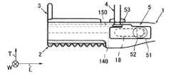
図1のマルチヘアカッターは、本体部材1と、刃部材2と、突起部材3と、指置き部材4と、摺動部材5とを含む。本体部材1は、前端部101と、後端部102とを有している。前端部101は、長手方向Lでみた本体部材1の中間部分から一端までの部分であって、刃部材2、突起部材3、指置き部材4及び摺動部材5が取り付けられている。後端部102は、長手方向Lでみた本体部材1の中間部から他端までの部分であって、ヘアカッターの把手を構成している。 The multi-hair cutter of FIG. 1 includes a
さらに、図1を参照すると、本体部材1は、第1の本体部11と、第2の本体部12とを含む。第1、第2の本体部11、12のそれぞれは、金型成型によるダイカスト製品、又は、射出成型による樹脂製品である。用いられる材料は、軽量性、材料コスト、耐腐食性などの観点から適宜選択することができる。一例として、第1、第2の本体部11、12がダイカスト製品の場合はアルミニウム(Al)又はアルミ合金などが好適であり、樹脂製品の場合にはポリカーボネート(PC)などが好適である。 Further, referring to FIG. 1, the
第1の本体部11は、前端部101に相当する部分に、内側面110を有している。内側面110は、長手方向Lに交差する幅方向Wの一方に設けられている凹段状の段差面であって、第2の本体部12の内側面120が組み合わされることにより、相対向面110、120間に、刃部材2、突起部材3、指置き部材4及び摺動部材5の取付部分が構成される。違う言葉で表現すれば、刃部材2、突起部材3、指置き部材4及び摺動部材5の取付部分を構成するため、第1、第2の本体部11、12の組み合わせによる半割り状の構造となっている。前端部101の内部構造については、図5乃至図8を参照して後述する。 The first
また、第1の本体部11は、後端部102に相当する部分に、リング状開口部13を有
している。リング状開口部13は、保持性及び操作性の観点から設けられるものであって、少なくとも一本の指を挿入するのに十分な大きさの内径を持っている。Further, the first
刃部材2は、図2に抜き出して示すように、刃体20と、刃保護体21とを有している。刃体20は、平面視、長方形形状の金属薄片であって、長手方向Lに交差する短手方向Tの一方に現れる長手端縁が鋭利な刃先を構成している。刃部材2の長さ寸法L2は、好ましくは40〜60mmであり、より好ましくは45〜55mmである。もっとも、長さ寸法L2は、マルチヘアカッターの用途に応じて適宜決定することができる。例えば、マルチヘアカッターが主にストロークカット用である場合、長さ寸法L2は45mm程度が好適である。 The
刃保護体21は、一枚の金属薄板を折り返して構成されており、折り返し部210を介して幅方向Wに向かい合う2つの挟持板面211、212を有している。挟持板面211、212のそれぞれは、刃体20と同程度又は刃体20よりも一回り大きな略長方形形状となっている。刃保護体21は、2つの挟持板面211、212の相対向面間に刃体20が案内され、案内された状態で向かい合う挟持板面211、212によって刃体20を挟持している。 The
挟持板面212は、端手方向Tでみて長手端縁が挟持板面211から突出している。さらに、刃保護体21は、挟持板面212において短手方向Tの一方に現れる長手端縁が櫛状歯213の列を構成している。櫛状歯213の列は、長手方向Lに隣接する櫛状歯213の相互間にギャップG1を有している。櫛状歯213は、刃体20の一面上に重なっており、重なった状態で刃体20の刃先が櫛状歯213の列によって交互に覆われ、刃先に露出部分201と非露出部分202とを生じさせている。 The sandwiching
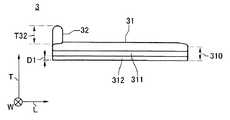
突起部材3は、AS樹脂(AS)、ABS樹脂(ABS)、ポリカーボネート(PC)、ポリエチレン(PE)、ポリプロピレン(PP)等の合成樹脂を用いた一体成型品であって、図3に抜き出して示すように、基体部31と、1つの突片32とを有している。 The protruding
基体部31は、長手方向Lに沿って伸びる棒状体であって、長手方向Lに交差する幅方向Wの両側に側面310を有している。側面310のそれぞれは、高さ方向Tでみた下側に凹部311と、凸部312とを有している。 The
凹部311は、底部313と、開口部314とを有し、側面310を、長手方向Lに沿って溝状に伸び、長手方向Lの両端面で切り欠き状に開口している。開口部314は、側面310の下辺から高さ方向Tに間隔D1を隔てた位置に開口し、底部313と幅方向Wに向かい合っている。底部313は、中心線CLからみて幅寸法W2を隔てた位置に形成され、側面310から幅方向WにW1の分だけ後退している。 The
凸部312は、側面310において、間隔D1に現れており、側面310と、底部313との前後差に応じた突出寸法W1を有している。違う言葉で表現すると、基体部31は、高さ方向Tでみた側面310の下側において、下辺から高さ方向Tに間隔D1を隔てた位置に、側面310と、底部313との前後差に応じたくびれ部分(幅寸法W3)を有している。 The
突片32は、基体部31の高さ方向Tの上側において、長手方向Lの一端に突設され、刃先とは反対の高さ方向Tに立ち上がっている。図3の突片32の高さ寸法T32は、10mmである。もっとも、突片32の設置数、及び、高さ寸法は、用途に応じて適宜設定することができる。 The protruding
指置き部材4は、AS樹脂(AS)、ABS樹脂(ABS)、ポリカーボネート(PC)、ポリエチレン(PE)、ポリプロピレン(PP)等の合成樹脂を用いた一体成型品であって、図4に抜き出して示すように、基体部41と、リング部42とを有している。 The finger placement member 4 is an integrally molded product using a synthetic resin such as AS resin (AS), ABS resin (ABS), polycarbonate (PC), polyethylene (PE), polypropylene (PP), etc. As shown, the
基体部41は、略円柱状、又は、略円盤状であって、周方向Cに交差する高さ方向Tでみた周面410の下側に凹部411と、凸部412とを有している。 The
凹部411は、底部413と、開口部414とを有し、周面410を、周方向Cに沿って伸びている。開口部414は、周面410の下辺から高さ方向Tに間隔D1を隔てた位置に開口し、底部413と径方向Wに向かい合っている。底部413は、周面410から径方向WにW1の分だけ後退している。 The
凸部412は、周面410において、間隔D1に現れており、周面410と、底部413との前後差に応じた突出寸法W1を有している。基体部41の高さ方向Tの下側について、違う言葉で表現すると、基体部41は、周面410の下辺から高さ方向Tに間隔D1を隔てた位置に、周面410と、底部413との前後差に応じたくびれ部分(W3)を有している。図3及び図4を参照すると、基体部31及び基体部41の下側は実質的に同一のくびれ部分を有し、長手方向Lからみたときに重なり合う。 The
リング部42は、貫通孔420を有し、基体部41の高さ方向Tの上面側に突設され、高さ方向Tに立ち上がっている。リング部42は、基体部41に対して、周方向C、及び/又は、径方向Wに可動的に結合されていることが好ましい。また、貫通孔420には、ヘアカッター使用者の指が挿通されるから、内寸法D420は、想定される使用者の指の太さに応じて、16〜23mmの範囲で適宜決定される。例えば、マルチヘアカッターを男性理容師向けに販売する場合には、内寸法D420を大きくすることができる。 The
図2乃至図4を参照して説明した刃部材2、突起部材3、指置き部材4及び摺動部材5は、前端部101に取り付けられる。次に、前端部101の内部構造について、図5乃至図8を参照して説明する。 The
図5乃至図8の本体部材1は、前端部101に、第1の収納部14と、第2の収納部15とを有している。第1の収納部14は、高さ方向Tでみた前端部101の下側を長手方向Lに沿って伸びており、刃部材2が着脱可能に取り付けられている。第1の収納部14は、収納空間140と、収納空間140に通じる開口端141とを有している。 The
収納空間140は、幅方向Wに向かい合う内側面110、120によって画定されている。内側面110、120は、高さ方向Tでみた下辺から間隔D2を隔てた位置まで湾曲して伸びており、曲面の始点と終点との間でギャップG2を有している。端的に言えば、内側面110、120は、刃部材2の外形形状に追従して湾曲している。 The
開口端141は、スリット状であって、前端部101の下側を長手方向Lに沿って伸びている。開口端141は、高さ方向Tでみた内側面110、120の下辺で構成されており、内側面110、120の下辺は、幅方向WにギャップG2を2倍した間隔を隔てて相対向している。刃部材2は、収納空間140に着脱可能に圧入され、圧入された状態で、刃体20の刃先が、開口端141を通じて外部に露出している。 The
第2の収納部15は、高さ方向Tでみた第1の収納部14の反対側において、前端部101を長手方向Lに沿って伸びており、突起部材3及び指置き部材4が上述した順序で着脱可能に取り付けられている。第2の収納部15は、収納空間150と、収納空間150に通じる開口端151とを有している。 The
収納空間150は、幅方向Wに向かい合う内側面110、120によって画定されている。内側面110、120は、図7に示すように、突起部材3及び指置き部材4のくびれ形状に追従した凹凸面構造を有している。より具体的に説明すると、第2の収納部15を構成する内側面110は、第1の凹段部161と、第2の凹段部162とを有している。 The
第1の凹段部161は、内側面110の上端から間隔D1を隔てた位置に開口し、内側面110から厚み方向に幅寸法W1の分だけ後退した位置に底面を有している。第2の凹段部162は、間隔D1に現れており、内側面110と、第1の凹段部161の底面との前後差に応じた幅寸法差W1を有している。違う言葉で表現すると、内側面110は、高さ方向Tでみた中間部分から上側が、第1の凹段部161の底面と、第2の凹段部162の底面との前後差(W1)に応じて階段状になっている。 The first recessed
収納空間150の内面は、左側面(図7)からみて、左右対称となっている。以下、簡単に説明すると、第2の凹段部162は、内側面120の上端から間隔D1を隔てた位置に開口し、内側面120から幅寸法W1の分だけ後退した位置に底面を有している。第2の凹段部162は、間隔D1に現れており、内側面120と、第1の凹段部161の底面との前後差に応じた幅寸法差W1を有している。 The inner surface of the
さらに、図6乃至図8を参照すると、第1、第2の本体部11、12は、相対向面110、120間に互いに雄雌嵌合可能な雌形嵌合部171と、雄形嵌合部172とを有している。この構造によると、雄形嵌合部172が雌形嵌合部171に嵌合されされた状態で、第1、第2の凹段部161、162の相対向面間に、突起部材3及び指置き部材4のくびれ形状に追従した収納空間150が形成される。 Further, referring to FIGS. 6 to 8, the first and second
収納空間150において、第2の凹段部162でみた相対向面110、120間の間隔は、第1の凹段部161でみた同間隔よりも幅寸法W1の分だけ幅方向Wに拡大されている。開口端151は、スリット状であって、前端部101の上側を長手方向Lに沿って伸びている。さらに、開口端151は、高さ方向Tでみた第1の凹段部161の上辺で構成されており、第1の凹段部161の上辺は、幅方向Wに幅寸法W2を2倍した間隔を隔てて相対向している。違う言葉で表現すれば、開口端151は、第2の凹段部162の相対向面間の距離よりも幅寸法W1の分だけ縮小されている。 In the
突起部材3、及び、指置き部材4は、長手方向Lの一端側から収納空間150に着脱可能に圧入され、圧入された状態で、突片32、及び、リング部42が、開口端151の外部に露出している。 The projecting
さらに図5乃至図8のマルチヘアカッターにおいて、第1の本体部11は、貫通孔18と、空洞部19とを有している。空洞部19は、相対向面110、120間において、高さ方向Tでみた中間部分に形成されている。貫通孔18は、平面視長穴であって、互いに交差する長軸と短軸とを有し、前記長軸が長手方向Lに沿っている。貫通孔18は、正面からみて空洞部19の領域内に開口し、空洞部19に貫通している。 Further, in the multi-hair cutter of FIGS. 5 to 8, the first
摺動部材5は、押し出し片51と、操作ボタン52とを有している。押し出し片51は、長手方向Lに現れる短手端縁に段状部53を有しており、空洞部19に収納された状態で、空洞部19を長手方向Lに沿って摺動する。操作ボタン52は、貫通孔18を通じて押し出し片51に軸止めされており、軸止めされた状態で押し出し片51を長手方向Lに摺動させる。次に、図9乃至図11を参照して、摺動部材5の目的、相互関係及び機能について説明する。 The sliding
図9は、摺動部材5について、刃部材2、突起部材3、指置き部材4を押す前の状態を示している。図9に示すように、押し出し片51は、空洞部19の内部において、短手端縁が刃部材2の端部、及び、指置き部材4の端部に位置決めされている。 FIG. 9 shows a state before the
図10は、摺動部材5について、刃部材2を押した後の状態を示している。図10に示すように、操作ボタン52を、貫通孔18の一端側から中央付近のポイントP1までスライドさせた場合、押し出し片51が、空洞部(19)の一端側から中央の位置まで移動し、段状部53の下段が刃部材2を押し、刃部材2を収納空間140に沿って長手方向Lに強制的に移動させ、前端部101の先端から刃部材2が押し出される。この状態で刃部材2を指でつまむことにより、収納空間140から刃部材2を抜き出すことができる。 FIG. 10 shows a state after the
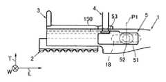
さらに図11に示すように、操作ボタン52を、貫通孔18の中央付近から他端側のポイントP2までスライドさせた場合、段状部53の上段が指置き部材4を長手方向Lに強制的に移動させ、指置き部材4によって押された突起部材3が、前端部101の先端から押し出される。この状態で突起部材3を指でつまむことにより、収納空間150から突起部材3を抜き出すことができる。図11からは必ずしも明らかではないが、突起部材3を抜き出した後、さらに指置き部材4を収納空間150から抜き出される。 Further, as shown in FIG. 11, when the
図1乃至図11を参照して説明したように、本発明の一実施形態に係るマルチヘアカッターは、前端部101に刃部材2が取り付けられているから、例えば、ストロークカット法において右手で後端部102を保持し、マルチヘアカッターを振り下ろす動作をすることにより、左手で保持している毛束の一部を刃部材2でカットするなど、通常の用法に従ったカット作業をすることができる。 As described with reference to FIG. 1 to FIG. 11, the multi-hair cutter according to one embodiment of the present invention has the
図1乃至図11のマルチヘアカッターは、上述したヘアカッターの基本的構成に加え、突起部材3を有する点に特徴の一つがある。突起部材3は突片32を有し、突片32は、基体部310の上側に突設され、刃部材2の刃先とは反対の高さ方向Tに立ち上がっている。この構造によると、例えば、ストロークカット法において、マルチヘアカッターを振り上げる動作で毛束の一部を突片32に引っ掛けて間引くことができる。即ち、図1乃至図11のマルチヘアカッターでは、上下往復操作中に毛束の一部を間引くことができるから、カット作業の作業効率が向上する。 The multi-hair cutter shown in FIGS. 1 to 11 is characterized in that it has a protruding
突起部材3は、前端部101に着脱可能に取り付けられているから、所望のヘアデザインにあわせて突起部材3を適宜交換し、多様なヘアデザインを実現することができる。しかも、突起部材3の着脱操作は、図9乃至図11を参照して説明したように、ヘアカッター使用者が、自分の親指または他の指によって、操作ボタン52を長手方向Lにスライドさせる操作で簡単に実行することができる。 Since the protruding
本発明は、突起部材3に加えて指置き部材4を有する点にもう一つの特徴がある。指置き部材4は、第2の収納部15において、突起部材3の後端側に取り付けられている。さらに指置き部材4を構成するリング部42は、基体部410の上側に突設され、刃部材2の刃先とは反対の方向(T)に立ち上がっている。この構造によると、例えば右手の人差し指をリング部42に挿通させることにより、人差し指の挿通方向と、刃部材2の延びる方向とが長手方向Lで一致し、人差し指の指す方向に刃体20の刃先が伸びることとなる。その結果、例えば、マルチヘアカッターを振り下ろす動作において、人差し指の示す方向に基づいて刃先の方向を認識し、髪に対する刃体20の角度を微調節することができるから、カット作業の正確性が向上する。従って、多様なヘアデザインを実現することができる。 The present invention has another feature in that the finger placing member 4 is provided in addition to the protruding
さらに、右手の人差し指をリング部42に挿通させることにより、人差し指の背面(手
の甲側)がリング部42の内面に突き当たり、ヘアカッター全体を吊り下げる状態となる。その結果、把手を強く握らなくてもヘアカッターを確実に保持することが可能となり、カット作業の正確性が向上する。従って、多様なヘアデザインを実現することができる。Further, by inserting the index finger of the right hand through the
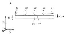
図12乃至図14は、本発明に係るマルチヘアカッターの突起部材3について、もう一つの実施形態を示す図である。図1乃至図11を参照して説明したように、突起部材3は、本体部材1に着脱可能に取り付けられているから、要求されるヘアデザインに応じて突起部材3を取り替えることができる。以下、図1乃至図11との相違点を中心に説明する。 FIG. 12 thru | or FIG. 14 is a figure which shows another embodiment about the
図12の実施形態では、突片32は、高さ寸法T2が図1乃至図11の突片32の半分程度、例えば5mmとなっている。図12の突起部材3を用いた場合、例えば、短い髪の人に対するカット作業の効率が向上する。 In the embodiment of FIG. 12, the
図13の実施形態では、4つの突片32が、基体部31の高さ方向Tの上側において、長手方向Lに沿って等配されている。また、図14の実施形態では、9つの突片32が、基体部31の高さ方向Tの上側において、長手方向Lに沿って等配されている。図13及び図14の実施形態によると、突起部材3を櫛として用いることにより、多様なヘアデザインを実現することができる。 In the embodiment of FIG. 13, the four projecting
図15は、本発明に係るマルチヘアカッターの突起部材3について、もう一つの実施形態を示す図である。図15の突起部材は、基体部31の下側の構造が図1乃至図14の実施形態とは異なる点で特徴がある。以下、図15乃至図18を参照して、図1乃至図14との相違点を中心に説明する。 FIG. 15 is a diagram showing another embodiment of the protruding
図15の突起部材は、切り欠き空間33と、係止部34と、掛止部35とを有している。切り欠き空間33は、正面視、凹状の空間であって、開口部と、天面と、2つの内側面331、332とを有し、長手方向Lでみた基体部31の中間部において、高さ方向Tの下側に開口している。天面は、正面(b)からみて凹部311の上辺に一致し、開口部と高さ方向Tに向かい合っている。2つの内側面331、332は、長手方向Lでみた天面の両端から高さ方向Tに沿って立ち上がり、長手方向Lで向かい合っている。 The protruding member shown in FIG. 15 has a
係止部34は、所謂ダンパーであって、アーム部340と、係止片341とを有している。アーム部340は、内側面331から長手方向Lに沿って、天面と平行に伸びている。アーム部340は、一端が内側面331と一体的に結合されて固定端となっており、他端が内側面332と間隔を隔てて自由端となっている。 The locking
さらに、アーム部340は、底面(c)から見て幅方向Wに向かい合う凹部311、311間のくびれに応じた幅寸法(W3)を有している。アーム部340は、高さ方向Tの下面が基体部31の底面と間隔G3を隔てており、且、高さ方向Tの上面が天面と間隔G4を隔てている。この構造によると、アーム部340は、外部から押し圧力に応じて、間隔G3、G4の範囲で高さ方向Tに沿って板バネ状に上下動することができる。 Further, the
係止片341は、アーム部340の高さ方向Tの下面において、長手方向Lの他端側に突設されており、突出端が開口部から外部に突出している。係止片341は、アーム部340の下面と一体的に結合されている。 The
掛止部35は、基体部31の高さ方向Tの下側において、長手方向Lの一端側に突設され、突片32とは反対の高さ方向Tに立ち上がっている。掛止部35は、基体部31の底面と一体的に結合されている。次に、図16乃至図18を参照して、係止部34及び掛止
部35の目的、相互関係及び機能について説明する。The latching
図16は、突起部材3を、第2の収納部15に取り付ける前の状態を示している。図16の第2の収納部15は、底面に、係止溝152と、掛止穴153とを有している。係止溝152は、長手方向Lでみた第2の収納部15の中間部に形成されており、係止片341と嵌合可能な凹形状を有している。掛止穴153は、長手方向Lでみた第2の収納部15の一端に形成されており、掛止部35と嵌合可能な凹形状を有している。 FIG. 16 shows a state before the protruding
図17は、突起部材3を、第2の収納部15に挿入している途中の状態を示している。図17に示すように、突起部材3を、第2の収納部15の一端に案内した場合、係止片341が第2の収納部15の底面に突き当たり、係止片341を通じて伝達される第2の収納部15の底面からの押し圧力によって、アーム部340が高さ方向Tに押し上げられ、間隔G4に退避する。 FIG. 17 shows a state in the middle of inserting the protruding
さらに図18に示すように、突起部材3を、第2の収納部15に挿入し続けると、掛止部35が掛止穴153に嵌合して突起部材3の挿入が規制され、この規制位置で係止溝152に係止片341が嵌合し、突起部材3が第2の収納部15の内部に固定される。 Further, as shown in FIG. 18, when the protruding
図16乃至図18を参照して説明したように、図15の突起部材3は、掛止部35を有するから、掛止部35がストッパーとして機能する。従って、突起部材3を第2の収納部15の適切な位置に取り付けることができる。 As described with reference to FIGS. 16 to 18, since the protruding
さらに、図15の突起部材3は、係止部34により、第2の収納部15の内部に固定されるから、カット作業時に加えられる外部からの物理的衝撃によって突起部材3が不正に脱落する問題は生じない。なお、突起部材3は、図9乃至図11を参照して説明した操作をすれば簡単に取り外しうることは言うまでもない。 Further, since the protruding
図19は、本発明のさらにもう一つの実施形態に係るマルチヘアカッターの正面図である。図19の実施形態は、本体部材1の形状が図1のマルチヘアカッターとは異なる点で特徴がある。以下、図19を参照して、図1との相違点を中心に説明する。 FIG. 19 is a front view of a multi-hair cutter according to still another embodiment of the present invention. The embodiment of FIG. 19 is characterized in that the shape of the
図19の実施形態は、前端部101が、後端部102に対して下降傾斜している。図19の下降傾斜角度θは15度であるが、必ずしもこれに限定する趣旨ではなく、0度以上30度以下の範囲で適宜調節することができる。例えば、マルチヘアカッターがストロークカット専用である場合、下降傾斜角度θは30度とすることができる。 In the embodiment of FIG. 19, the
図19の実施形態によると、把手を構成する後端部102を握って、指置き部材4の貫通孔(420)に人差し指を挿通させた場合に、手の甲と人差し指との間の角度(下降傾斜角度θ)が確保されることにより、人間工学の観点から握りやすくなる。その結果、作業効率が向上する。 According to the embodiment of FIG. 19, when the index finger is inserted into the through hole (420) of the finger placing member 4 by grasping the
また、図19の実施形態によると、把手を構成する後端部102を握って、手首や肘を支点として上下(又は前後)に振った場合、下降傾斜している分だけ前端部101の振り幅が大きくなる。従って、作業効率が向上する。 Further, according to the embodiment of FIG. 19, when the
図20は、本発明のさらにもう一つの実施形態に係るマルチヘアカッターの正面図である。図20の実施形態は、図1のマルチヘアカッターとは、指置き部材4の構造が異なる点に特徴がある。以下、図21を参照し、図1との相違点を中心に説明する。 FIG. 20 is a front view of a multi-hair cutter according to still another embodiment of the present invention. The embodiment of FIG. 20 is characterized in that the structure of the finger rest member 4 is different from the multi-hair cutter of FIG. Hereinafter, the difference from FIG. 1 will be mainly described with reference to FIG.
図21の指置き部材4は、AS樹脂(AS)、ABS樹脂(ABS)、ポリカーボネー
ト(PC)、ポリエチレン(PE)、ポリプロピレン(PP)等の合成樹脂を用いた一体成型品であって、基体部41と、指受け皿部43とを有している。The finger placement member 4 in FIG. 21 is an integrally molded product using a synthetic resin such as AS resin (AS), ABS resin (ABS), polycarbonate (PC), polyethylene (PE), polypropylene (PP), etc. It has a
指受け皿部43は、上面が凹状に湾曲し、基体部41の高さ方向Tの上側に形成されている。指受け皿部43は、ヘアカッター使用者が指を載置するために用いられるものであるから、指受け皿部43の曲率は、想定される使用者の性別、特にヘアカッター使用者の指の太さに応じて、適宜決定することができる。 The
基体部41の高さ方向Tの下側には、図3及び図4を参照して説明したとの同じくびれ部分が形成されており、このくびれ部分によって、指置き部材4が、本体部材1に着脱可能に取り付けられている。 On the lower side of the
図20及び図21の実施形態によっても、図1乃至図19を参照して説明した利点を全て有することができる。さらに、指置き部材4は、本体部材1に着脱可能に取り付けられているから、図1乃至図19の指置き部材4を、図20及び図21の指置き部材4に交換することにより、ヘアカッター使用者が、各々の使い勝手に応じてマルチヘアカッターの構成を自由に変更することができる。 20 and 21 may have all of the advantages described with reference to FIGS. Furthermore, since the finger placement member 4 is detachably attached to the
図22は、本発明のさらにもう一つの実施形態に係るマルチヘアカッターの正面図であって、指置き部材4を用いない場合の構成を示している。図22のマルチヘアカッターでは、指置き部材4に対応する部分が被覆部材6によって覆われている。図22からは明らかではないが、被覆部材6は、突起部材3、及び、指置き部材4と同様のくびれ構造を有していることが好ましい。 FIG. 22 is a front view of a multi-hair cutter according to still another embodiment of the present invention, and shows a configuration when the finger placement member 4 is not used. In the multi-hair cutter of FIG. 22, a portion corresponding to the finger placing member 4 is covered with the covering member 6. Although not apparent from FIG. 22, the covering member 6 preferably has a constricted structure similar to that of the protruding
図22の実施形態によっても、マルチヘアカッターは、少なくとも突起部材3を有するから、図1乃至図19を参照して説明した利点を全て有することができる。 Also in the embodiment of FIG. 22, the multi-hair cutter has at least the protruding
以上、好ましい実施例を参照して本発明の内容を具体的に説明したが、本発明の基本的技術思想及び教示に基づいて、当業者であれば、種種の変形態様を採り得ることは自明である。 Although the contents of the present invention have been specifically described above with reference to the preferred embodiments, it is obvious that those skilled in the art can take various modifications based on the basic technical idea and teachings of the present invention. It is.
1 本体部材
2 刃部材
3 突起部材
31 基体部
32 突片
4 指置き部材
41 基体部
42 リング部DESCRIPTION OF
Claims (2)
Translated fromJapanese前記刃部材は、前記本体部材の高さ方向の一方に取り付けられており、
前記突起部材は、基体部と、少なくとも1つの突片とを有しており、
前記基体部は、前記本体部材の前記高さ方向の他方において、前記刃部材の反対側に着脱可能に取り付けられており、
前記突片は、前記基体部に突設され、前記刃部材とは反対の方向に立ち上がっている、マルチヘアカッター。A multi-hair cutter including a main body member, a blade member, and a protruding member,
The blade member is attached to one of the main body members in the height direction,
The protruding member has a base portion and at least one protruding piece,
The base portion is detachably attached to the opposite side of the blade member on the other side of the main body member in the height direction,
The multi-hair cutter, wherein the protruding piece protrudes from the base portion and rises in a direction opposite to the blade member.
前記指置き部材は、第2の基体部と、リング部とを有しており、
前記第2の基体部は、前記本体部材の前記高さ方向の他方において、前記刃部材の反対側に着脱可能に取り付けられており、
前記リング部は、前記第2の基体部に突設され、前記刃部材とは反対の方向に立ち上がっている、
マルチヘアカッター。The multi-hair cutter according to claim 1, further comprising a finger placement member,
The finger placement member has a second base portion and a ring portion,
The second base portion is detachably attached to the opposite side of the blade member on the other side of the main body member in the height direction,
The ring portion protrudes from the second base portion and rises in a direction opposite to the blade member.
Multi hair cutter.
Priority Applications (4)
| Application Number | Priority Date | Filing Date | Title |
|---|---|---|---|
| JP2009275484AJP4553974B1 (en) | 2009-12-03 | 2009-12-03 | Multi hair cutter |
| US12/942,438US8701291B2 (en) | 2009-12-03 | 2010-11-09 | Multi-purpose hair cutter |
| CN201010556519XACN102085671A (en) | 2009-12-03 | 2010-11-18 | Multi-purpose hair cutter |
| KR1020100121402AKR20110063343A (en) | 2009-12-03 | 2010-12-01 | Multi hair cutter |
Applications Claiming Priority (1)
| Application Number | Priority Date | Filing Date | Title |
|---|---|---|---|
| JP2009275484AJP4553974B1 (en) | 2009-12-03 | 2009-12-03 | Multi hair cutter |
Publications (2)
| Publication Number | Publication Date |
|---|---|
| JP4553974B1true JP4553974B1 (en) | 2010-09-29 |
| JP2011115382A JP2011115382A (en) | 2011-06-16 |
Family
ID=42978747
Family Applications (1)
| Application Number | Title | Priority Date | Filing Date |
|---|---|---|---|
| JP2009275484AActiveJP4553974B1 (en) | 2009-12-03 | 2009-12-03 | Multi hair cutter |
Country Status (4)
| Country | Link |
|---|---|
| US (1) | US8701291B2 (en) |
| JP (1) | JP4553974B1 (en) |
| KR (1) | KR20110063343A (en) |
| CN (1) | CN102085671A (en) |
Families Citing this family (18)
| Publication number | Priority date | Publication date | Assignee | Title |
|---|---|---|---|---|
| USD648897S1 (en)* | 2010-07-27 | 2011-11-15 | Panasonic Electric Works Co., Ltd. | Electric shaver |
| USD648896S1 (en)* | 2010-07-27 | 2011-11-15 | Panasonic Electric Works Co., Ltd. | Electric shaver |
| USD650131S1 (en)* | 2010-07-27 | 2011-12-06 | Panasonic Electric Works Co., Ltd. | Electric shaver |
| USD649290S1 (en)* | 2010-07-27 | 2011-11-22 | Panasonic Electric Works Co., Ltd. | Electric shaver |
| USD648486S1 (en)* | 2010-07-27 | 2011-11-08 | Panasonic Electric Works Co.,Ltd. | Electric shaver |
| WO2012028171A1 (en)* | 2010-08-30 | 2012-03-08 | Bic-Violex Sa | Protective cover for razor cartridge |
| US8839521B2 (en)* | 2011-02-01 | 2014-09-23 | Terri D. Hazard | Hair cutting apparatus |
| USD648898S1 (en)* | 2011-03-04 | 2011-11-15 | Panasonic Electric Works Co., Ltd. | Electric shaver |
| US10131062B1 (en) | 2014-01-31 | 2018-11-20 | Dryfhout Enterprises, Llc | Body shaver with comb and blade |
| US12280512B2 (en) | 2014-01-31 | 2025-04-22 | Bakblade Limited | Safety razor with comb and blade |
| US9718200B2 (en)* | 2014-01-31 | 2017-08-01 | Dryfhout Enterprises, Llc | Safety razor with comb and integrated blade and associated methods |
| US10500744B1 (en) | 2014-01-31 | 2019-12-10 | Dryfhout Properties, Llc | Safety razor with plurality of comb and integrated blade groups |
| US10315322B1 (en) | 2016-05-17 | 2019-06-11 | Dryfhout Properties, Llc | Method of using a back shaver handle |
| US11077570B2 (en) | 2014-01-31 | 2021-08-03 | Dryfhout Properties, Llc | Flexible back shaver |
| US10449683B2 (en) | 2014-05-09 | 2019-10-22 | Litomi LLC | Razor comb hair tool |
| US10493643B1 (en) | 2016-05-17 | 2019-12-03 | Dryfhout Properties, Llc | Leveled back shaver |
| US10543609B2 (en) | 2016-05-17 | 2020-01-28 | Dryfhout Properties, Llc | Elevated shaver |
| US9937629B1 (en) | 2016-05-17 | 2018-04-10 | Dryfhout Enterprises, Llc | Two-point discrimination safety razor assembly |
Family Cites Families (26)
| Publication number | Priority date | Publication date | Assignee | Title |
|---|---|---|---|---|
| US1654117A (en)* | 1926-10-13 | 1927-12-27 | Firm Vereinigte Celluloidwaren | Hairdressing implement |
| US2288299A (en) | 1940-10-03 | 1942-06-30 | Vincent R Pileggi | Combined comb and thinning razor |
| US3134382A (en)* | 1961-07-28 | 1964-05-26 | David S Broman | Hair cutting device |
| US3536080A (en)* | 1968-10-15 | 1970-10-27 | James E Player | Hair grooming device |
| US4009517A (en)* | 1973-04-16 | 1977-03-01 | Horn Robert E | Barbering tool |
| US4037322A (en)* | 1974-10-15 | 1977-07-26 | Bresler Albert E | Razor adapted for surgical preparation |
| US3990461A (en)* | 1975-06-11 | 1976-11-09 | Lawrence Peska Associates, Inc. | Razor cut comb brush |
| US4344226A (en)* | 1980-04-17 | 1982-08-17 | Blake Joseph W Iii | Disposable safety razor |
| US4401129A (en)* | 1981-09-08 | 1983-08-30 | Luque Fortino C | Comb and cut baton |
| JPS5951877A (en)* | 1982-09-20 | 1984-03-26 | 松下電工株式会社 | Hair cutter |
| US4487211A (en)* | 1983-05-02 | 1984-12-11 | Sullivan Judy C | Shearing comb |
| US4709475A (en)* | 1986-09-11 | 1987-12-01 | Phung Ha T | Combination comb, hair trimmer and safety razor |
| DE8811140U1 (en)* | 1988-09-03 | 1988-10-13 | Wilkinson Sword GmbH, 5650 Solingen | Razor or thinning knife |
| US5146810A (en)* | 1989-06-16 | 1992-09-15 | Mueller Lawrence P | Grip system for hand tools and instruments |
| JPH03182554A (en) | 1989-12-13 | 1991-08-08 | Mitsubishi Gas Chem Co Inc | Polyamide resin composition for molding |
| JP3182554B2 (en) | 1995-03-14 | 2001-07-03 | 足立工業株式会社 | Replacement blade for hair comb razor and razor for hair comb |
| JPH09313751A (en)* | 1996-05-24 | 1997-12-09 | Rintaro Ono | Barber/beauty hairdressing scissors type hair razor |
| US5794348A (en)* | 1996-10-01 | 1998-08-18 | Scott; Mike | Clipper comb |
| JPH1190060A (en)* | 1997-09-18 | 1999-04-06 | Adachi Kogyo:Kk | Razor holder |
| US6381855B1 (en)* | 2001-04-20 | 2002-05-07 | Ching-Hsiung Lin | Knife-holding assist |
| US6588108B2 (en)* | 2001-04-27 | 2003-07-08 | Victor C. Talavera | Hair trimming device with removably mountable components for removal of split ends and styling of hair |
| US7243428B2 (en)* | 2002-10-25 | 2007-07-17 | Japan Lanka Trading Co., Ltd. | Hair brush and replaceable cutting unit for hair brush |
| JP2005160915A (en)* | 2003-12-05 | 2005-06-23 | Sanpo Shoji Kk | Eyebrow cover for razor |
| JP4504676B2 (en)* | 2003-12-25 | 2010-07-14 | 株式会社貝印刃物開発センター | Hair cutter |
| KR100637428B1 (en)* | 2004-12-17 | 2006-10-24 | 박혜산 | Hairdressing cutting equipment |
| US20090142463A1 (en)* | 2007-12-04 | 2009-06-04 | Brian William Hayes | Double Handle Kitchen Knife |
- 2009
- 2009-12-03JPJP2009275484Apatent/JP4553974B1/enactiveActive
- 2010
- 2010-11-09USUS12/942,438patent/US8701291B2/ennot_activeExpired - Fee Related
- 2010-11-18CNCN201010556519XApatent/CN102085671A/enactivePending
- 2010-12-01KRKR1020100121402Apatent/KR20110063343A/ennot_activeWithdrawn
Also Published As
| Publication number | Publication date |
|---|---|
| JP2011115382A (en) | 2011-06-16 |
| US20110131811A1 (en) | 2011-06-09 |
| US8701291B2 (en) | 2014-04-22 |
| KR20110063343A (en) | 2011-06-10 |
| CN102085671A (en) | 2011-06-08 |
Similar Documents
| Publication | Publication Date | Title |
|---|---|---|
| JP4553974B1 (en) | Multi hair cutter | |
| US10449683B2 (en) | Razor comb hair tool | |
| KR101743128B1 (en) | Handle assembly cartridge, and razor having these | |
| JP3028541U (en) | Universal knife | |
| US8539961B2 (en) | Hair cutting comb with T-top member | |
| CN104903060B (en) | razor | |
| US20050011072A1 (en) | Razor with integral trimming wand | |
| WO2008029566A1 (en) | Hand tool | |
| GB2384976A (en) | Hair brush with retractable bristles | |
| US20090007443A1 (en) | Personal Razor Device | |
| US12370711B2 (en) | Systems and methods for trimming dreadlocks | |
| JP3581845B2 (en) | Hairdressing scissors combination structure | |
| JP5690976B2 (en) | comb | |
| US6247234B1 (en) | Razor and blade | |
| JP4131236B2 (en) | Eyelash forming tool | |
| JP4131235B2 (en) | Eyelash forming tool | |
| HK1153984A (en) | Multi-purpose hair cutter | |
| JP3135418U (en) | Safety razor with slide cover | |
| US20060217752A1 (en) | Hair trimmer | |
| CN217572988U (en) | Arc hair cutter | |
| CN223013233U (en) | Push-to-pop type manual shaver | |
| KR200406858Y1 (en) | Nail clippers with built-in earpicks | |
| JP4718632B2 (en) | Scissors | |
| CN205799612U (en) | A kind of Multi-function electric razor | |
| KR200404371Y1 (en) | a nail clipper having an ear-pick within. |
Legal Events
| Date | Code | Title | Description |
|---|---|---|---|
| TRDD | Decision of grant or rejection written | ||
| A975 | Report on accelerated examination | Free format text:JAPANESE INTERMEDIATE CODE: A971005 Effective date:20100702 | |
| A01 | Written decision to grant a patent or to grant a registration (utility model) | Free format text:JAPANESE INTERMEDIATE CODE: A01 Effective date:20100707 | |
| A01 | Written decision to grant a patent or to grant a registration (utility model) | Free format text:JAPANESE INTERMEDIATE CODE: A01 | |
| A61 | First payment of annual fees (during grant procedure) | Free format text:JAPANESE INTERMEDIATE CODE: A61 Effective date:20100713 | |
| FPAY | Renewal fee payment (event date is renewal date of database) | Free format text:PAYMENT UNTIL: 20130723 Year of fee payment:3 | |
| R150 | Certificate of patent or registration of utility model | Free format text:JAPANESE INTERMEDIATE CODE: R150 Ref document number:4553974 Country of ref document:JP Free format text:JAPANESE INTERMEDIATE CODE: R150 | |
| R250 | Receipt of annual fees | Free format text:JAPANESE INTERMEDIATE CODE: R250 | |
| R250 | Receipt of annual fees | Free format text:JAPANESE INTERMEDIATE CODE: R250 | |
| R250 | Receipt of annual fees | Free format text:JAPANESE INTERMEDIATE CODE: R250 | |
| R250 | Receipt of annual fees | Free format text:JAPANESE INTERMEDIATE CODE: R250 | |
| R250 | Receipt of annual fees | Free format text:JAPANESE INTERMEDIATE CODE: R250 | |
| R250 | Receipt of annual fees | Free format text:JAPANESE INTERMEDIATE CODE: R250 | |
| R250 | Receipt of annual fees | Free format text:JAPANESE INTERMEDIATE CODE: R250 | |
| R250 | Receipt of annual fees | Free format text:JAPANESE INTERMEDIATE CODE: R250 |