JP4553892B2 - Semiconductor device and manufacturing method thereof - Google Patents
Semiconductor device and manufacturing method thereofDownload PDFInfo
- Publication number
- JP4553892B2 JP4553892B2JP2006352801AJP2006352801AJP4553892B2JP 4553892 B2JP4553892 B2JP 4553892B2JP 2006352801 AJP2006352801 AJP 2006352801AJP 2006352801 AJP2006352801 AJP 2006352801AJP 4553892 B2JP4553892 B2JP 4553892B2
- Authority
- JP
- Japan
- Prior art keywords
- film
- semiconductor device
- wiring
- ring
- seal ring
- Prior art date
- Legal status (The legal status is an assumption and is not a legal conclusion. Google has not performed a legal analysis and makes no representation as to the accuracy of the status listed.)
- Expired - Fee Related
Links
Images


Classifications
- H—ELECTRICITY
- H01—ELECTRIC ELEMENTS
- H01L—SEMICONDUCTOR DEVICES NOT COVERED BY CLASS H10
- H01L23/00—Details of semiconductor or other solid state devices
- H01L23/52—Arrangements for conducting electric current within the device in operation from one component to another, i.e. interconnections, e.g. wires, lead frames
- H01L23/522—Arrangements for conducting electric current within the device in operation from one component to another, i.e. interconnections, e.g. wires, lead frames including external interconnections consisting of a multilayer structure of conductive and insulating layers inseparably formed on the semiconductor body
- H01L23/532—Arrangements for conducting electric current within the device in operation from one component to another, i.e. interconnections, e.g. wires, lead frames including external interconnections consisting of a multilayer structure of conductive and insulating layers inseparably formed on the semiconductor body characterised by the materials
- H01L23/53204—Conductive materials
- H01L23/53209—Conductive materials based on metals, e.g. alloys, metal silicides
- H01L23/53228—Conductive materials based on metals, e.g. alloys, metal silicides the principal metal being copper
- H01L23/53238—Additional layers associated with copper layers, e.g. adhesion, barrier, cladding layers
- H—ELECTRICITY
- H01—ELECTRIC ELEMENTS
- H01L—SEMICONDUCTOR DEVICES NOT COVERED BY CLASS H10
- H01L23/00—Details of semiconductor or other solid state devices
- H01L23/52—Arrangements for conducting electric current within the device in operation from one component to another, i.e. interconnections, e.g. wires, lead frames
- H01L23/522—Arrangements for conducting electric current within the device in operation from one component to another, i.e. interconnections, e.g. wires, lead frames including external interconnections consisting of a multilayer structure of conductive and insulating layers inseparably formed on the semiconductor body
- H01L23/532—Arrangements for conducting electric current within the device in operation from one component to another, i.e. interconnections, e.g. wires, lead frames including external interconnections consisting of a multilayer structure of conductive and insulating layers inseparably formed on the semiconductor body characterised by the materials
- H01L23/5329—Insulating materials
- H01L23/53295—Stacked insulating layers
- H—ELECTRICITY
- H01—ELECTRIC ELEMENTS
- H01L—SEMICONDUCTOR DEVICES NOT COVERED BY CLASS H10
- H01L2924/00—Indexing scheme for arrangements or methods for connecting or disconnecting semiconductor or solid-state bodies as covered by H01L24/00
- H01L2924/0001—Technical content checked by a classifier
- H01L2924/0002—Not covered by any one of groups H01L24/00, H01L24/00 and H01L2224/00
- H—ELECTRICITY
- H01—ELECTRIC ELEMENTS
- H01L—SEMICONDUCTOR DEVICES NOT COVERED BY CLASS H10
- H01L2924/00—Indexing scheme for arrangements or methods for connecting or disconnecting semiconductor or solid-state bodies as covered by H01L24/00
- H01L2924/10—Details of semiconductor or other solid state devices to be connected
- H01L2924/11—Device type
- H01L2924/12—Passive devices, e.g. 2 terminal devices
- H01L2924/1204—Optical Diode
- H01L2924/12044—OLED
Landscapes
- Physics & Mathematics (AREA)
- Condensed Matter Physics & Semiconductors (AREA)
- General Physics & Mathematics (AREA)
- Engineering & Computer Science (AREA)
- Computer Hardware Design (AREA)
- Microelectronics & Electronic Packaging (AREA)
- Power Engineering (AREA)
- Internal Circuitry In Semiconductor Integrated Circuit Devices (AREA)
Description
Translated fromJapaneseこの発明は半導体装置及びその製造方法に関し、特にシールリングを具える半導体装置及びその製造方法に関する。 The present invention relates to a semiconductor device and a manufacturing method thereof, and more particularly to a semiconductor device including a seal ring and a manufacturing method thereof.
近年の半導体装置における素子の集積度及び性能の向上に伴って、配線自体の微細化及び配線間隔のさらなる極小化が求められている。製造プロセスの微細化の進行により、配線遅延が動作律速になってきていることから、配線材料をより低抵抗の銅(Cu)、或いは銅合金とする銅配線技術が開発されてきている。配線材料としての銅或いは銅合金は、エッチング技術による加工が困難である。従って、いわゆるダマシン法と呼ばれる製造方法が採用されるのが一般的である。 With recent improvements in the degree of integration and performance of elements in semiconductor devices, miniaturization of wiring itself and further minimization of wiring spacing are required. With the progress of miniaturization of the manufacturing process, the wiring delay has become the rate-determining operation, and therefore, copper wiring technology has been developed in which the wiring material is made of copper (Cu) or copper alloy having a lower resistance. Copper or copper alloy as a wiring material is difficult to process by an etching technique. Therefore, a so-called damascene method is generally employed.
このダマシン法は、具体的には、絶縁膜に配線溝を形成し、この配線溝を埋め込む銅合金薄膜を堆積した後、銅合金薄膜をその上側から研削することにより、配線溝を埋め込む部分のみを残存させ、埋込み配線を形成する方法である。この銅合金薄膜の研削工程には、CMP(Chemical Mechanical Polishing)法が適用されている。 Specifically, this damascene method forms a wiring groove in an insulating film, deposits a copper alloy thin film that embeds this wiring groove, and then grinds the copper alloy thin film from the upper side so that only the part that embeds the wiring groove is formed. In this method, the embedded wiring is formed. A CMP (Chemical Mechanical Polishing) method is applied to the grinding process of the copper alloy thin film.
また、このような銅配線技術を採用するにあたり、特に配線容量を低減するために、従来用いられていたシリコン酸化膜に代わり、より誘電率の低い、すなわち比誘電率(k)が約4.2から約1.5程度の低誘電率の材料を用いるいわゆる低誘電率膜が絶縁膜として用いられている。 Further, in adopting such a copper wiring technique, in order to reduce the wiring capacity, in particular, in place of the conventionally used silicon oxide film, the dielectric constant is lower, that is, the relative dielectric constant (k) is about 4. A so-called low dielectric constant film using a low dielectric constant material of about 2 to about 1.5 is used as the insulating film.
このような低誘電率膜、特に多孔質の膜は、界面密着性といった機械的特性(Modulus,Hardness)の低さから、例えばダマシン法におけるCMP工程、個片化工程といった低誘電率膜に応力がかかる工程において、この低誘電率膜とこれに接触している他の絶縁膜或いはシールリングといった他の構造との界面に剥離等の損傷が発生して半導体装置の電気的特性を損なうおそれがある。 Such low dielectric constant films, particularly porous films, have low mechanical properties such as interfacial adhesion (Modulus, Hardness), and stress is applied to the low dielectric constant films such as the CMP process and the individualization process in the damascene method. In such a process, there is a possibility that damage such as peeling occurs at the interface between the low dielectric constant film and another structure such as a seal ring or other structure in contact with the low dielectric constant film, thereby impairing the electrical characteristics of the semiconductor device. is there.
ダマシン法及び低誘電率膜を採用した従来の半導体装置において、特にダイシング時の損傷が素子領域に達するのを防止する目的で、素子領域を連続的に取り囲む、いわゆるシールリングを設けた半導体装置及びその製造方法が知られている(例えば、特許文献1参照。)。
上述の従来のシールリングは、個片化工程時の素子領域外で発生するクラック(剥離)の素子領域への波及を効果的に防止することができる。 The above-described conventional seal ring can effectively prevent the crack (peeling) generated outside the element region during the singulation process from spreading to the element region.
しかしながら、低誘電率膜とこれと接触するシールリングとの界面での剥離はシールリングに起因する場合もある。 However, peeling at the interface between the low dielectric constant film and the seal ring in contact therewith may be caused by the seal ring.
上述の従来のシールリングの構成によれば、シールリングの素子領域側の界面で発生する剥離、すなわちクラックの発生及びこのクラックの素子領域への伝播を防止するには十分ではない。 According to the configuration of the above-described conventional seal ring, it is not sufficient to prevent peeling occurring at the interface on the element region side of the seal ring, that is, generation of a crack and propagation of this crack to the element region.
従って、例えばCMP工程により、低誘電率膜とシールリングとの界面に大きな応力がかかった場合に、シールリングの素子領域側の界面で発生するクラックの発生及びこのクラックの素子領域への伝播を防止するための技術が嘱望されている。 Therefore, for example, when a large stress is applied to the interface between the low dielectric constant film and the seal ring by a CMP process, cracks generated at the interface on the element region side of the seal ring and propagation of the cracks to the element region are prevented. Technology to prevent it is envied.
この発明は、上述の課題に鑑みてなされたものである。この課題を解決するにあたり、この発明の半導体装置は、下記のような構成を具えている。 The present invention has been made in view of the above-described problems. In solving this problem, the semiconductor device of the present invention has the following configuration.
すなわち、この発明の半導体装置は、上面及び当該上面と対向する下面を有していて、機能素子が設けられている素子領域及び当該素子領域を囲む周辺領域が設定されている基板と、前記基板の上側に設けられている絶縁膜と、前記絶縁膜を貫通するシールリング用溝を埋め込んで前記周辺領域に設けられているリング部を含むシールリングとを具えている。
前記リング部は、前記絶縁膜を貫通する配線用溝を埋め込んで前記素子領域に設けられた銅を材料とする配線を含む配線層と同一層に設けられており、前記素子領域の周囲を囲む環状のリング本体、及び当該リング本体から前記素子領域側に突出する複数の突出部を有し、かつ前記リング本体の周辺領域側には突出部を有しない。
前記複数の突出部は、前記上面に沿った平面形状が凹凸を有する四角形状である突出部を含む。That is, the semiconductor device of the present invention has an upper surface and a lower surface opposite to the upper surface, the substrate is provided with an element region in which a functional element is provided and a peripheral region surrounding the element region, and thesubstrate And a seal ring including a ring portionprovided in the peripheral region by embedding a seal ring groove penetrating the insulating film .
The ring portion is provided in the same layer as a wiring layer including wiring made of copper provided in the element region by filling a wiring groove penetrating the insulating film, and surrounds the periphery of the element region. It has an annular ring body and a plurality of protrusions protruding from the ring body toward the element region, and does not have a protrusion on the peripheral region side of the ring body.
The plurality of protrusions include protrusions whose planar shape along the upper surface is a quadrangular shape having irregularities.
また、この発明の半導体装置の製造方法は、下記のような工程を含んでいる。 In addition, the semiconductor device manufacturing method of the present invention includes the following steps.
すなわち、複数の配線層が互いに層間絶縁膜により離間されて積層されている多層配線構造を具えている半導体装置の製造方法は、上面及びこの上面と対向する下面を有していて、素子領域及びこの素子領域を囲む周辺領域が設定されている基板を準備する工程と、周辺領域に、素子領域の周囲を囲む環状のリング本体、及びこのリング本体から素子領域側に突出する複数の突出部を有し、かつリング本体の周辺領域側には突出部を有さないリング部を配線層と同一層に形成する配線層形成工程と、複数の配線層同士及び基板の上面と最下層の配線層とを離間する層間絶縁膜を貫通する環状の埋込み部により各配線層に形成されているリング部同士を隙間なく互いに接続する工程とを含んでいる。
そして、前記配線層形成工程において、複数の突出部が、前記上面に沿った平面形状が凹凸を有する四角形状である突出部を含むように、リング部を形成する。That is, a method of manufacturing a semiconductor device having a multilayer wiring structure in which a plurality of wiring layers are stacked with a space between each other by an interlayer insulating film has an upper surface and a lower surface opposite to the upper surface, A step of preparing a substrate in which a peripheral region surrounding the element region is set, an annular ring body surrounding the periphery of the element region, and a plurality of protrusions protruding from the ring body toward the element region side A wiring layer forming step of forming a ring portion having no protrusion on the peripheral region side of the ring main body in the same layer as the wiring layer, and a plurality of wiring layers and the upper and lowermost wiring layers of the substrate Connecting the ring portions formed in each wiring layer to each other without a gap by an annular embedded portion penetrating the interlayer insulating film spaced apart from each other.
Then, in the wiring layer forming step, the ring portion is formed so that the plurality of protrusions include protrusions whose planar shape along the upper surface is a quadrangular shape having irregularities.
上述したこの発明の半導体装置は、特に素子領域側に突出した複数の突出部を有するシールリングを具えていることを特徴としている。 The above-described semiconductor device of the present invention is characterized in that it includes a seal ring having a plurality of projecting portions that project to the element region side.
これら複数の突出部は、いわゆるテクノロジーノードが許容する範囲で任意好適な形状とすることができるが、好ましくは例えばいずれも同一形状、及び同一サイズとするのがよい。さらにこれら突出部は、シールリングの延在方向に対して同一方向に並列配置し、かつ隣接する突出部同士の離間距離を等間隔とすることができる。 The plurality of protrusions can have any suitable shape as long as the so-called technology node allows, but preferably all have the same shape and the same size, for example. Furthermore, these protrusions can be arranged in parallel in the same direction with respect to the extending direction of the seal ring, and the separation distances between the adjacent protrusions can be equally spaced.
また、複数の隣接する突出部同士の離間距離は、好ましくは例えば最小でも、使用される露光装置の光学系の解像限界により規定される最小間隔とすることができる。 Further, the separation distance between the plurality of adjacent protrusions is preferably a minimum distance defined by the resolution limit of the optical system of the exposure apparatus used, for example, at a minimum.
さらに、複数の突出部の平面形状は、好ましくは例えば、いずれも長方形であり、長方形の短辺又は長辺はシールリングの延在方向に対して垂直方向に配置されており、この長方形は使用される露光装置の光学系の解像限界により規定される最小サイズとするのがよい。 Further, the planar shape of the plurality of protrusions is preferably, for example, all rectangular, and the short side or long side of the rectangle is arranged in the direction perpendicular to the extending direction of the seal ring, and this rectangle is used. The minimum size defined by the resolution limit of the optical system of the exposure apparatus to be used is preferable.
この発明の半導体装置の構成によれば、シールリングとこれと接触する絶縁膜との接触面積を大幅に増加することができる。従って、例えばCMP工程により発生する応力が、増加した接触面積に分散するため、特に低誘電率膜と他の構造との界面における剥離の発生を効果的に防止することができる。According to the configuration of the semiconductor device of the present invention, the contact area between the seal ring and the insulating film in contact with the seal ring can be greatly increased. Therefore, for example, the stress generated by the CMP process is dispersed in the increased contact area, so that it is possible to effectively prevent the occurrence of peeling particularly at the interface between the low dielectric constant film and another structure.
また、この発明の半導体装置の製造工程によれば、このような構成を具える半導体装置を効率的に製造することができる。 Further, according to the semiconductor device manufacturing process of the present invention, a semiconductor device having such a configuration can be efficiently manufactured.
以下、図面を参照して、この発明の実施の形態につき説明する。なお、図面には、この発明が理解できる程度に各構成成分の形状、大きさ及び配置関係が概略的に示されているに過ぎず、従って、この発明は特に図示例にのみ限定されるものではない。 Hereinafter, embodiments of the present invention will be described with reference to the drawings. It should be noted that the drawings only schematically show the shapes, sizes, and arrangement relationships of the constituent components to such an extent that the present invention can be understood. Therefore, the present invention is particularly limited only to the illustrated examples. is not.
また、以下の説明において、特定の材料、条件及び数値条件等を用いることがあるが、これらは好適例の1つに過ぎず、従って、この発明は何らこれら好適例に限定されるものではない。 In the following description, specific materials, conditions, numerical conditions, and the like may be used. However, these are only preferred examples, and the present invention is not limited to these preferred examples. .
さらに、以下の説明に用いる各図において、同様の構成成分については、同一の符号を付して示し、その重複する説明を省略する場合もあることを理解されたい。 Furthermore, in each figure used for the following description, it is to be understood that the same constituent components are denoted by the same reference numerals and redundant description thereof may be omitted.
(半導体装置の構成例1)
図1、図2及び図3を参照して、この発明の半導体装置の構成例につき詳細に説明する。(Configuration Example 1 of Semiconductor Device)
A configuration example of the semiconductor device of the present invention will be described in detail with reference to FIGS.
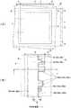
図1(A)は個片化直前の1つの半導体装置に着目して上面側からみた部分平面図であり、図1(B)は図1(A)に示した部分領域Aを拡大して示す部分拡大図である。なお、下側に位置する各配線層が具える同様の構成についても図2に対応させて符号を付してある。 FIG. 1A is a partial plan view from the upper surface side, focusing on one semiconductor device just before singulation, and FIG. 1B is an enlarged view of the partial region A shown in FIG. FIG. In addition, the same structure which each wiring layer located in the lower side is provided with the code | symbol corresponding to FIG.
図2は、図1(B)のI−I’一点鎖線で切断した切断面を示す部分断面概略図である。 FIG. 2 is a partial cross-sectional schematic view showing a cut surface taken along a dashed line I-I ′ of FIG.
図3は、特にシールリングに着目した図2と同様の部分断面概略図である。 FIG. 3 is a partial cross-sectional schematic view similar to FIG. 2 focusing particularly on the seal ring.
この発明の半導体装置は、基板と、この基板上に設けられていて、素子領域(アクティブ領域)を囲むシールリングを具えている。そして、この発明の半導体装置は、このシールリングの形状に特徴を有している。 The semiconductor device of the present invention includes a substrate and a seal ring which is provided on the substrate and surrounds an element region (active region). The semiconductor device according to the present invention is characterized by the shape of the seal ring.
この点につき、以下、順に説明する。 This point will be described below in order.
まず、図2に示すように、半導体装置10は、基板20を含んでいる。基板20は、好ましくは例えばシリコンウェハといった半導体基板である。 First, as shown in FIG. 2, the
基板20は、上面20a及びこの上面20aと対向する下面20bとを有している。この基板20には、個片化されたときに半導体装置10となるチップ領域11が設定されている。なお、この図示例では、個片化工程時に研削されるスクライブラインSLがチップ領域11の境界線となっている。 The
図1(A)に示すように、基板20には、トランジスタといった機能素子が設けられる、矩形状の素子領域12及びこの素子領域12を囲む周辺領域14が設定されている。 As shown in FIG. 1A, a
この基板20上には、複数の配線層、すなわちこの構成例では第1配線層40、第2配線層60及び第3配線層80と、これら複数の配線層を互いに離間する例えばこの構成例では第1から第6までの絶縁膜30、42、54、62、74及び82、すなわち複数層の層間絶縁膜とが設けられている。 On this
すなわち、基板20上に、第1絶縁膜30、第1配線層40、第3絶縁膜54、第2配線層60、第5絶縁膜74、及び第3配線層80が順次に階層的に積層されている階層構造が形成されている。また、第2絶縁膜42は、第1配線層40の階層に含まれており、第4絶縁膜62は、第2配線層60の階層に含まれており、さらに第6絶縁膜82は、第3配線層80の階層に含まれている。 That is, the first insulating
図1(A)及び(B)に示すように、この発明にかかるシールリング16は、素子領域12を囲む周辺領域14に設けられていて、素子領域12を囲むリング本体16aを有している。すなわち、リング本体16aは閉じた環状の形状としてある。この例ではリング本体16aの外形の輪郭は、素子領域12の形状に対応した好ましくは例えば四角形状となっている。このように、リング本体16aの延在形状は、素子領域12又はチップ領域11の形状に応じた任意好適な形状とすることができる。すなわち、素子領域12は、一体的な壁状に構成されるシールリング16により隙間なくその周囲を囲まれている。 As shown in FIGS. 1A and 1B, a
図1(B)に示すように、シールリング16は、さらに、リング本体16aと一体的に形成されている、複数の突出部16bを具えている。この突出部16bは、リング本体16aから素子領域12側に突出している。この図示例では、突出部16bの平面形状は、後述する製造方法、特にフォトリソグラフィ工程が許容する範囲内で、任意のサイズ、また任意の形状とすることができる。この図示例では、突出部16bは、1つの角隅を切り欠いた凹凸を有する四角形状、長方形状、台形状、サイズの異なるさらなる長方形状といった複数種類の形状を任意に組み合わせた形状としてある。また、これら各形状の部分の配置間隔、すなわち相互の離間距離についても後述する製造方法、特にフォトリソグラフィ工程が許容する範囲内で、任意好適なものとすることができる。すなわち、複数の突出部16bは、形状、サイズ、または隣接する突出部同士の離間距離のいずれかが同一であっても、または、形状、サイズ、及び隣接する突出部同士の離間距離が異なっていてもよい。As shown in FIG. 1B, the
なお、周辺領域14には、上述の複数の配線層それぞれを貫通するリング本体16a及び突出部16bが設けられている。以下、リング本体16a及び突出部16bを総称して、単にリング部とも称する。 The
図2に示す構成例では、シールリング16は、埋込み部と、この埋込み部の頂面を除く壁面に設けられているバリアメタルとを具えている。図2及び図3を参照してより具体的に説明すると、第1絶縁膜30を貫通してシールリング用第1埋込み部35が設けられている。第2絶縁膜42を貫通してシールリング用第1バリアメタル45Aが設けられているシールリング用第2埋込み部46Aが第1リング部48として設けられている。第3絶縁膜54及び第4絶縁膜62を貫通して、シールリング用第2バリアメタル65Aが設けられているシールリング用第3埋込み部66Aが第2リング部68として設けられている。さらに第5絶縁膜74及び第6絶縁膜82を貫通して第3バリアメタル85が設けられている第4埋込み部86が第3リング部88として設けられている。 In the configuration example shown in FIG. 2, the
このようにして、基板20の所要の領域と、第3配線層80の埋込み部86とは、その間に設けられた埋込み部35、46A、66Aとバリアメタル45A、65A、85を経て連続的に結合された状態となる。 In this manner, the required region of the
このようにリング部のリング本体16aは環状に設けられている、すなわちシールリング16は、これらリング部同士及びリング部と基板とを離間する絶縁膜を貫通してこれらを互いに接続する環状の埋込み部により構成されている。結果として、素子領域12は、一体的な壁状に構成されるシールリング16により隙間なくその周囲を囲まれる。 Thus, the ring
以下、このシールリング16につきさらに詳細に説明するが、以下の構成例の説明においては、各配線層40、60及び80に設けられている第1、第2及び第3リング部48、68及び88の特に突出部16bの形状をいずれも同一であるものとして説明する。しかしながら、この発明の半導体装置は同一形状の突出部16bに限定されず、各配線層ごとに異なる形状及び/又はサイズのリング本体16a及び突出部16bを有するリング部を設ける構成とすることができる。 Hereinafter, the
基板20の上面20a側には、詳細は省略するが例えば拡散層24により構成されるトランジスタ等からなる複数の機能素子が設けられている。さらに基板20には、例えばSTI(Shallow Trench Isolation)、LOCOS(Local Oxidation of Silicon)といった機能素子を電気的に分離する素子分離構造22が設けられている。 On the
これら拡散層24及び素子分離構造22上、すなわち基板20の上面20a上には、第1絶縁膜30が設けられている。 A first insulating
この第1絶縁膜30は、例えばシリコン酸化膜とすればよい。 The first insulating
第1絶縁膜30の素子領域12内には、この第1絶縁膜30を貫通して、この例では拡散層24として示す素子に至るコンタクトホール32が設けられている。 A
また、第1絶縁膜30の周辺領域14内には、この第1絶縁膜30を貫通して、基板上面20aに至るシールリング用第1溝33が設けられている。 Further, in the
このシールリング用第1溝33は、素子領域12を閉環状に囲んでいる。 The first
コンタクトホール32内にはこれを埋め込む埋込みコンタクト34が設けられている。埋込みコンタクト34は、例えばタングステン(W)といった従来公知の導電性材料により構成すればよい。 A buried
シールリング用第1溝33も同様に、例えばタングステンといった従来公知の導電性材料により埋め込んでシールリング用第1埋込み部35として構成すればよい。埋込みコンタクト34とシールリング用第1埋込み部35とは、好ましくは同一の材料により形成するのがよい。 Similarly, the seal ring
なお、第1絶縁膜30がシリコン酸化膜で形成されている場合には、シールリング用第1埋込み部35は、一続きに素子領域12を隙間なく囲む形状とする必要はなく、例えば埋込みコンタクト34と同様の複数の柱状の構造とし、複数の柱状体として構成されるシールリング用第1埋込み部35が素子領域12を囲む列柱状に配置される構成としてもよい。 In the case where the first insulating
第1絶縁膜30及びこの第1絶縁膜30から露出する埋込みコンタクト34及びシールリング用第1埋込み部35上には、第1拡散防止膜41が設けられている。この第1拡散防止膜41は、特に配線の材料として用いられる銅の拡散を防止するための膜である。 A first
第1拡散防止膜41は、例えばシリコン窒化膜、又はシリコンカーバイド(SiC)膜とすればよい。 The first
この第1拡散防止膜41上には第2絶縁膜42が積層されている。 A second insulating
第2絶縁膜42は、シリコン酸化膜と比較して、比誘電率の小さい低誘電率膜とするのがよい。具体的には、比誘電率(k)が好ましくは最大でも3.0である従来公知の低誘電率膜(Low−k膜)、例えばHSQ:二酸化ケイ素水素シルセスシオキサン(hydrogen silsesquioxane)、MSQ:メチルシルセスシオキサン(methyl silsesquioxane)、CDO(carbon doped oxide)といった材料或いはダウケミカル社製SiLK(登録商標)といったポリマー材料を材料とする膜とすればよい。 The second insulating
このとき、第2絶縁膜42の膜厚は、好ましくは100nmから5000nmの範囲内のいずれかの値とするのがよい。 At this time, the thickness of the second insulating
さらに第2絶縁膜42の表面上には、第1キャップ膜43が設けられている。キャップ膜とは、例えば高密度のシリコン酸化膜により構成される低誘電率膜を保護する機能を奏する膜である。 Further, a
第1溝部44は、第1キャップ膜43の表面から、第1キャップ膜43、第2絶縁膜42及び第1拡散防止膜41を貫通して、第1絶縁膜30の表面に至って設けられている。 The
この第1溝部44は、埋込みコンタクト34及びシールリング用第1埋込み部35の頂面を露出させて設けてある。 The
第1溝部44は、配線用第1溝44Bとシールリング用第2溝44Aとを含んでいる。配線用第1溝44Bは、素子領域12内の埋込みコンタクト34の直上に設けられてその頂面を露出させている。シールリング用第2溝44は、周辺領域14内のシールリング用第1埋込み部35の直上に設けられてその頂面を露出させている。 The
図1(B)にも示すように、このシールリング用第2溝44Aは、リング本体16aと上述した突出部16bの輪郭を画成する第1突出領域44Aaとを有している。 As shown in FIG. 1B, the second groove for
第1溝部44内の表面には、第1バリアメタル45が設けられている。すなわちシールリング用第1埋込み部35の頂面上を含むシールリング用第2溝44A内の表面には、シールリング用第1バリアメタル45Aが設けられている。また、埋込みコンタクト34の頂面上を含む配線用第1溝44B内の表面には配線用第1バリアメタル45Bが設けられている。 A
このシールリング用第1バリアメタル45Aは、シールリング用第2溝44Aの第1突出領域44Aaの輪郭に沿った、この例ではいわゆるつづら折れ形状の屈曲部45Aaを有している。 The
第1バリアメタル45としては、好ましくは例えばタンタル、窒化タンタル、タングステン、窒化タングステン、WSiN、窒化チタン及びTiSiNを含む群から選択される単層膜又は2層以上の積層膜とすればよい。 The
第1バリアメタル45の膜厚は、好ましくは例えば2nmから50nmの範囲内のいずれかの値とすればよいが、このバリアメタルの膜厚はいわゆるテクノロジーノードに対応した最適な膜厚とすればよい。 The film thickness of the
第1バリアメタル45上、すなわち、第1バリアメタル45に覆われた第1溝部44には、これを埋め込む、例えば銅又は銅合金からなる第2埋込み部46が設けられている。 On the
この第2埋込み部46は、第1配線層40の本質的な構成要素である。すなわち第2埋込み部46は、第1配線層40に含まれる複数の配線を構成する配線用第1埋込み部46Bとシールリング用第2埋込み部46Aとを含んでいる。 The second embedded
配線用第1埋込み部46Bは、配線用第1溝44Bを埋め込んで設けられている。また、シールリング用第2埋込み部46Aは、シールリング用第2溝44Aを埋め込んで設けられている。 The first wiring embedded
これら配線用第1埋込み部46B及びシールリング用第2埋込み部46Aの頂面は第1キャップ膜43の表面と実質的に同一高さとされている。 The top surfaces of the first embedded portion for wiring 46 </ b> B and the second embedded portion for
なお、図3にも示すように、このシールリング用第2埋込み部46Aと上述のシールリング用第1バリアメタル45Aとで上述した第1リング部48を構成している。 As shown in FIG. 3, the
第1キャップ膜43、第1バリアメタル45及び埋込み部46上には、第1拡散防止膜41と同様の構成を有する第2拡散防止膜52が設けられている。 On the
この第2拡散防止膜52上には第3絶縁膜54が積層されている。第3絶縁膜54は、既に説明した第2絶縁膜42と同様の低誘電率膜である。 A third insulating
さらに第3絶縁膜54上には、第1拡散防止膜41と同様の構成の第3拡散防止膜61が設けられている。 Further, a third
第3拡散防止膜61上には第4絶縁膜62が積層されている。第4絶縁膜62は、既に説明した第2絶縁膜42と同様の低誘電率膜である。 A fourth insulating
この第4絶縁膜62上には、第1キャップ膜43と同様の構成を有する第2キャップ膜63が設けられている。 A
これら第2拡散防止膜52、第3絶縁膜54、第3拡散防止膜61、第4絶縁膜62、及び第2キャップ膜63には、これらを貫通する第2溝部56が設けられている。 The second
この第2溝部56には、周辺領域14に設けられているシールリング用第3溝56Aと素子領域12に設けられている配線用第2溝56Bとが含まれる。 The
第2溝部56は、この発明の各配線層の形成工程に採用されるダマシン法を適用することを考慮して構成されている。ここでは特に上層配線層を形成する際に下層配線層に接続される埋込みヴィアを同時に埋め込んで形成するいわゆるデュアルダマシン法を採用した構成例につき説明する。 The
第2拡散防止膜52及び第3絶縁膜54には、これらを貫通して、シールリング用第2埋込み部46Aの頂面の一部分に至るシールリング用下部溝56Aa及び配線用第2埋込み部46Bの頂面の一部分に至る配線用下部ヴィアホール56Baが設けられている。シールリング用下部溝56Aaは周辺領域14に設けられている。また、配線用下部ヴィアホール56Baは素子領域12に設けられている。 The second
第3拡散防止膜61、第4絶縁膜62及び第2キャップ膜63には、これらを貫通し、下部溝56Aaよりも幅広のシールリング用上部溝56Ab及び下部ヴィアホール56Baの径よりも幅広の配線用上部溝56Bbが設けられている。シールリング用上部溝56Abは周辺領域14に設けられている。また、配線用上部溝56Bbは素子領域12に設けられている。 The third
すなわち、シールリング用第3溝56Aは、溝幅のみが異なる同一形状のシールリング用下部溝56Aaとシールリング用上部溝56Abとが上下に連通して構成されている。また、配線用第2溝56Bは、配線用下部ヴィアホール56Baと配線用上部溝56Bbが連通して構成されている。 That is, the third
このようにシールリング用第3溝56A及び配線用第2溝56Bは、溝同士又は溝とヴィアホールとを組み合わせた2段の構成とされている。 Thus, the seal ring
図1(B)にも示すように、このシールリング用第3溝56Aは、リング本体16aと上述した突出部16bとの輪郭を画成する第2突出領域56Acを有している。 As shown in FIG. 1B, the third groove for
第2溝部56内の表面には、既に説明した第1バリアメタル45と同様の構成の第2バリアメタル65が設けられている。すなわちシールリング用第2埋込み部46Aの頂面の一部分を含むシールリング用第3溝56A内の表面には、シールリング用第2バリアメタル65Aが設けられている。また、配線用第1埋込み部46Bの頂面の一部分上を含む配線用第2溝56B内の表面には配線用第2バリアメタル65Bが設けられている。 A
このシールリング用第2バリアメタル65Aは、シールリング用第3溝56Aの第2突出領域56Acの輪郭に沿った形状の屈曲部65Aaを有している。 The
第2バリアメタル65上、すなわち、第2バリアメタル65に覆われたシールリング用第3溝56A及び配線用第2溝56Bには、これらを埋め込む、例えば銅又は銅合金からなる第3埋込み部66が設けられている。 On the
この第3埋込み部66は、第2配線層60の本質的な構成要素である。すなわち第3埋込み部66は、第2配線層60に含まれる複数の配線を構成する配線用第2埋込み部66Bとシールリング用第3埋込み部66Aとを含んでいる。 The third embedded
配線用第2埋込み部66Bは、配線用第2溝56Bを埋め込んで設けられている。また、シールリング用第3埋込み部66Aは、シールリング用第3溝56Aを埋め込んで設けられている。 The wiring second embedded
これら配線用第2埋込み部66B及びシールリング用第3埋込み部66Aの頂面は第2キャップ膜63の表面と実質的に同一の高さとされている。 The top surfaces of the second embedded portion for wiring 66B and the third embedded portion for
なお、図3にも示すように、このシールリング用第3埋込み部66Aと上述のシールリング用第2バリアメタル65Aとで上述した第2リング部68を構成している。 As shown also in FIG. 3, the
この例では、シールリング用下部溝56Aaとシールリング用上部溝56Abとが連通して構成されているシールリング用第3溝56Aと、配線用下部ヴィアホール56Baと配線用上部溝56Bbとが連通して構成されている配線用第2溝56Bとを単一の工程で一体的な構成として埋め込むいわゆるデュアルダマシン法を採用した構成例を説明したが、例えばシールリング用下部溝56Aaとシールリング用上部溝56Abとを、それぞれ個別の工程で埋め込むシングルダマシン法により形成される、個別の埋込み部を接続する構成としてもよい。 In this example, the seal ring lower groove 56Aa and the seal ring upper groove 56Ab communicate with each other, the seal ring
第2キャップ膜63、第2バリアメタル65及び第3埋込み部66上には、第1拡散防止膜41と同様の構成を有する第4拡散防止膜72が設けられている。 On the
この第4拡散防止膜72上には第5絶縁膜74が積層されている。第5絶縁膜74は、既に説明した第2絶縁膜42と同様の低誘電率膜である。 A fifth insulating
さらに第5絶縁膜74上には、第1拡散防止膜41と同様の構成の第5拡散防止膜81が設けられている。 Further, a fifth
第5拡散防止膜81上には第6絶縁膜82が積層されている。第6絶縁膜82は、既に説明した第2絶縁膜42と同様の低誘電率膜である。 A sixth insulating
この第6絶縁膜82上には、第1キャップ膜43と同様の構成を有する第3キャップ膜83が設けられている。 A
これら第4拡散防止膜72、第5絶縁膜74、第5拡散防止膜81、第6絶縁膜82、及び第3キャップ膜83には、これらを貫通する第3溝部76が設けられている。 The fourth
第3溝部76及びこれを埋め込む後述する埋込み部については、第2溝部56及び第3埋込み部66の構成と何ら変わるところがないため、構成についてのみ説明する。 The
この第3溝部76は、周辺領域14に設けられている。すなわち、シールリング16の一部分を構成する溝部である。 The
第3溝部76は、第2溝部56と同様に、この発明の各配線層の形成工程に採用されるダマシン法を適用することを考慮して構成されている。 Similar to the
第4拡散防止膜72及び第5絶縁膜74には、これらを貫通して、シールリング用第3埋込み部66Aの頂面の一部分に至るシールリング用下部溝76Aが設けられている。シールリング用下部溝76Aは周辺領域14に設けられている。 The fourth
第5拡散防止膜81、第6絶縁膜82及び第3キャップ膜83には、これらを貫通し、下部溝76Aよりも幅広のシールリング用上部溝76Bが設けられている。シールリング用上部溝76Bは周辺領域14に設けられている。 The fifth
すなわち、第3溝部76は、溝幅のみが異なる同一形状のシールリング用下部溝76Aとシールリング用上部溝76Bとが上下に連通して構成されている。 That is, the
図1(B)にも示すように、この第3溝部76の特にシールリング用上部溝76Bは、リング本体16aと上述した突出部16bとの輪郭を画成する第3突出領域76Baを有している。 As shown in FIG. 1B, the seal groove
第3溝部76内の表面には、既に説明した第1バリアメタル45と同様の構成の第3バリアメタル85が設けられている。すなわちシールリング用第3埋込み部66Aの頂面の一部分を含む第3溝部76の表面には、シールリング用の第3バリアメタル85が設けられている。 A
この第3バリアメタル85は、第3溝部76の第3突出領域76Baの輪郭に沿った形状の屈曲部85Aを有している。 The
第3バリアメタル85上、すなわち、第3バリアメタル85に覆われた第3溝部76には、これらを埋め込む、例えば銅又は銅合金からなる第4埋込み部86が設けられている。 On the
この第4埋込み部86は、第3配線層80の本質的な構成要素である。 The fourth embedded
第4埋込み部86は、第3溝部76を埋め込んで設けられている。第4埋込み部86の頂面は第3キャップ膜83の表面と実質的に同一の高さとされている。 The fourth embedded
なお、図3にも示すように、この第4埋込み部86と上述の第3バリアメタル85とで上述した第3リング部88を構成している。 As shown in FIG. 3, the fourth embedded
この発明の半導体装置の構成例によれば、シールリングと、特にこのシールリングと接触する絶縁膜との接触面積を大幅に増加することができる。従って、例えばダマシンプロセスに必須のCMP工程により発生する応力が増加した接触面積に分散するため、特に低誘電率膜とシールリングとの界面における剥離の発生を効果的に防止することができる。 According to the configuration example of the semiconductor device of the present invention, the contact area between the seal ring and, in particular, the insulating film in contact with the seal ring can be greatly increased. Therefore, for example, stress generated by the CMP process essential to the damascene process is dispersed in the increased contact area, so that it is possible to effectively prevent the occurrence of peeling particularly at the interface between the low dielectric constant film and the seal ring.
(半導体装置の製造方法例)
以下、図を参照して、上述した構成を有するこの発明の半導体装置の製造方法につき説明する。(Example of semiconductor device manufacturing method)
A method for manufacturing a semiconductor device of the present invention having the above-described configuration will be described below with reference to the drawings.
図4(A)及び(B)は、製造途中で得られた構造体を図2と同じ位置で切断した切り口を示す模式図である。 4 (A) and 4 (B) are schematic views showing a cut surface obtained by cutting the structure obtained in the course of manufacture at the same position as FIG.
図5は、図4(B)から続く模式図である。 FIG. 5 is a schematic diagram continuing from FIG.
図6は、図5から続く模式図である。 FIG. 6 is a schematic diagram continuing from FIG.
図7は、図6から続く模式図である。 FIG. 7 is a schematic diagram continuing from FIG.
図4(A)に示すように、まず、好ましくは例えばシリコンウェハといった基板20を準備する。 As shown in FIG. 4A, first, a
基板20には、スクライブラインSLに沿って研削個片化したときに半導体装置となるチップ領域11を設定する。また、このチップ領域11内には、電気的にアクティブな素子領域12及びこの素子領域12を囲む周辺領域14を設定しておく。 On the
次いで、基板20に、素子を電気的に分離するための素子分離構造22を常法に従って形成する。 Next, an
既に説明したように、素子分離構造としては、例えばSTI(Shallow Trench Isolation)、LOCOS(Local Oxidation of Silicon)が想定されている。 As already described, for example, STI (Shallow Trench Isolation) and LOCOS (Local Oxidation of Silicon) are assumed as the element isolation structure.
次いで、基板20に、例えば拡散層24により構成されるトランジスタ等の複数の機能素子を形成する。この素子形成工程は、従来公知のイオン打ち込み工程及び拡散工程を任意好適な条件で実施すればよい。 Next, a plurality of functional elements such as transistors configured by the
これら拡散層24及び素子分離構造22上に、第1絶縁膜30を形成する。 A first insulating
この第1絶縁膜30は、既に説明したように例えばシリコン酸化膜が想定されている。第1絶縁膜30は、CVD法といった任意好適な条件での従来公知の成膜方法により形成すればよい。 As described above, for example, a silicon oxide film is assumed as the first insulating
次いで、第1絶縁膜30に、この第1絶縁膜30を貫通して、この例では素子領域12内の拡散層24として示す機能素子に至るコンタクトホール32を形成する。同時に、周辺領域14内である第1絶縁膜30には、この第1絶縁膜30を貫通して基板上面20aに至り、素子領域12を閉環状に囲んでいるシールリング用第1溝33を形成する。 Next, a
これらコンタクトホール32及びシールリング用第1溝33は、常法に従う任意好適な条件で、一連のレジスト塗布工程、ホトリソグラフィ工程によるレジストパターンの形成工程、かかるレジストパターンをマスクとして用いるエッチング工程により形成すればよい。 The
次に、コンタクトホール32を埋め込む埋込みコンタクト34を常法に従って形成する。また、同時にシールリング用第1溝33も、例えばタングステンといった従来公知の導電性材料により埋め込んでシールリング用第1埋込み部35とする。 Next, a buried
埋込みコンタクト34及びシールリング用第1埋込み部35は、例えばタングステン(W)といった従来公知の導電性材料を用いて形成すればよい。 The buried
埋込みコンタクト34及びシールリング用第1埋込み部35の形成工程は、コンタクトホール32及びシールリング用第1溝33をスパッタ法等の従来公知の方法に従って同時に埋め込む工程とするのがよい。さらにエッチバック工程を行って、埋込みコンタクト34及びシールリング用第1埋込み部35を形成すればよい。このエッチバック工程により埋込みコンタクト34及びシールリング用第1埋込み部35の頂面は、第1絶縁膜30の表面の高さとほぼ同一の高さとなる。 The step of forming the buried
次いで、第1絶縁膜30及びこの第1絶縁膜30から露出する埋込みコンタクト34及びシールリング用第1埋込み部35上に、第1拡散防止膜41を形成する。 Next, a first
第1拡散防止膜41は、例えばシリコン窒化膜、又はシリコンカーバイド(SiC)膜を従来公知のCVD法等により任意好適な条件で成膜することにより形成すればよい。 The first
さらにこの第1拡散防止膜41上に、第2絶縁膜42を積層する。 Further, a second insulating
第2絶縁膜42は、既に説明したように、比誘電率(k)が好ましくは最大でも3.0である従来公知の低誘電率膜(Low−k膜)、例えばHSQ(hydrogen silsesquioxane)、MSQ(methyl silsesquioxane)、CDO(carbon doped oxide)といった材料或いはダウケミカル社製SiLK(登録商標)といったポリマー材料を材料として成膜すればよい。 As described above, the second insulating
第2絶縁膜42の成膜工程は、選択された膜材料に応じた工程、例えば従来公知の塗布法、CVD法により形成すればよい。 The second insulating
次に、第2絶縁膜42の表面上に、第1キャップ膜43を積層する。キャップ膜としては、例えば高密度のシリコン酸化膜を形成するのがよい。 Next, the
この第1キャップ膜43は、具体的には高密度のシリコン酸化膜を従来公知のプラズマCVD法により任意好適な条件で成膜すればよい。 Specifically, the
次いで、第1溝部44を形成する。第1溝部44、すなわち第1突出領域44Aaを有しているシールリング用第2溝44A及び配線用第1溝44Bを、第1キャップ膜43の表面から、第1キャップ膜43、第2絶縁膜42及び第1拡散防止膜41を貫通して、第1絶縁膜30の表面に至るよう形成する。 Next, the
第1溝部44は、従来公知のホトリソグラフィ工程、及び第1キャップ膜43、第2絶縁膜42及び第1拡散防止膜41を構成する材料に応じた任意好適な条件でのエッチング工程により各膜をパターニングすることにより、所望のパターンとして形成すればよい。 The
次に、第1溝部44内の表面を覆う第1バリアメタル45を形成する。 Next, a
まず、露出面全面、すなわち第1キャップ膜43の表面及び形成された第1溝部44内、すなわち側壁、露出した第1絶縁膜30の表面、埋込みコンタクト34の頂面及びシールリング用第1埋込み部35の頂面上を覆う第1バリアメタル膜45Xを成膜する。 First, the entire exposed surface, that is, the surface of the
この第1バリアメタル膜45Xとしては、好ましくは例えばタンタル、窒化タンタル、タングステン、窒化タングステン、WSiN、窒化チタン及びTiSiNを含む群から選択される従来公知の材料を、これら材料に応じた任意好適な手法により成膜して単層膜又は2層以上の積層膜とすればよい。 As the first
第1バリアメタル膜45Xは、バリアメタルの膜厚はいわゆるテクノロジーノードに対応した最適な膜厚として形成すればよい。この膜厚は、好ましくは例えば2nmから50nmの範囲内のいずれかの値として形成すればよい。 The first
次に、第1バリアメタル膜45X上、すなわち、第1バリアメタル膜45Xに覆われている第1溝部44を例えば銅合金で埋め込み、かつ露出面全面を覆う第1配線膜46Xを成膜する。 Next, a
この第1配線膜46Xを銅合金膜として形成する工程は、例えば2段階の工程により行うのがよい。具体的には、まず、第1段階は、従来公知のPVD法により露出面全面に対し、銅合金の膜を好ましくは膜厚20nmから150nmの範囲内で堆積させる。次いで第2段階として、好ましくは従来公知の電解メッキ法、CVD法又は無電解メッキ法により、第1溝部44を埋め込む第1配線膜46Xを形成すればよい。 The step of forming the
次に、図4(B)に示すように、第1バリアメタル膜45X及び第1配線膜46Xを、第1キャップ膜43の表面が露出するまで、すなわち配線用第1埋込み部46B及びシールリング用第2埋込み部46Aの頂面は第1キャップ膜43の表面と実質的に同一高さとなるよう平坦に研削する。この研削工程によって、第1溝部44、すなわちシールリング用第2溝44A内の表面を覆っていて、シールリング用第2溝44Aの第1突出領域44Aaの輪郭に沿った形状の屈曲部45Aa(図1(B)参照。)を有しているシールリング用第1バリアメタル45A、配線用第1溝44B内の表面を覆う配線用第1バリアメタル45B、第1配線層40に含まれる複数の配線を構成する配線用第1埋込み部46B、及び第1突出部46Aaを有するシールリング用第2埋込み部46Aを完成させる。すなわち、第1バリアメタル45Aと第2埋込み部46Aとを有する第1リング部48が形成される(図3参照。)。 Next, as shown in FIG. 4B, the first
この研削工程は、任意好適な条件で行われる従来公知のCMP工程により行うのがよい。好適なCMP工程の条件を、一般的な技術水準として例示すると、研磨圧力を2.5psiから4.5psi程度の範囲とし、研磨パッドと研磨面との相対速度を60m/分から180m/分程度の範囲内のいずれかの値とする。 This grinding process is preferably performed by a conventionally known CMP process performed under any suitable conditions. Examples of suitable CMP process conditions as a general technical level include a polishing pressure in the range of about 2.5 psi to 4.5 psi, and a relative speed between the polishing pad and the polishing surface of about 60 m / min to about 180 m / min. Any value within the range.
シールリング用第1バリアメタル45Aは屈曲部45Aaを有している。従って、この屈曲部が存在する分だけ絶縁膜との接触面積を増加させることができる。よって、このCMP工程により発生する応力が増加した接触面積に分散するため、特に低誘電率膜と他の構造との界面における剥離の発生を効果的に防止することができる。 The
図4(B)に示すように、次いで、露出した第1キャップ膜43、第1バリアメタル45及び第2埋込み部46上に、既に説明した第1拡散防止膜41と同様の工程を実施して、第2拡散防止膜52を形成する。 Next, as shown in FIG. 4B, a process similar to that of the already described first
さらに、第2拡散防止膜52上に、既に説明した第2絶縁膜42と同様の工程を実施して、低誘電率膜である第3絶縁膜54を積層する。 Further, a third insulating
形成された第3絶縁膜54上に、第1拡散防止膜41と同様の工程を実施して、第3拡散防止膜61を積層する。 A third
次いで、第3拡散防止膜61上に、既に説明した第2絶縁膜42と同様の工程を実施して、低誘電率膜である第4絶縁膜62を積層する。 Next, a fourth insulating
さらに、第4絶縁膜62上に、既に説明した第1キャップ膜43と同様の工程を実施して、第2キャップ膜63を形成する。 Further, the
次いで、これら第2拡散防止膜52、第3絶縁膜54、第3拡散防止膜61、第4絶縁膜62、及び第2キャップ膜63に、これらを貫通する第2溝部56を形成する。 Next, a
第2溝部56は、従来公知のホトリソグラフィ工程、及び各積層膜を構成する材料に応じた任意好適な条件でのエッチング工程により各膜をパターニングすることにより、所望のパターンとして形成すればよい。 The
第2溝部56を形成するにあたり、まず、シールリング用前駆第3溝56AX及び配線用前駆第2溝56BXを形成する。 In forming the
シールリング用前駆第3溝56AXを、周辺領域14に形成する。このシールリング用前駆第3溝56AXの形成により、第2拡散防止膜52、第3絶縁膜54、第3拡散防止膜61、第4絶縁膜62、及び第2キャップ膜63を貫通してシールリング用第2埋込み部46Aの頂面の一部分が露出する。 A seal ring precursor
配線用前駆第2溝56BXは、素子領域12に、第2拡散防止膜52、第3絶縁膜54、第3拡散防止膜61、第4絶縁膜62、及び第2キャップ膜63を貫通させて配線用第1埋込み部46Bの頂面の一部分を露出させて形成する。なお、配線用前駆第2溝56BXは、この例では貫通孔として形成する。 The wiring precursor second groove 56BX penetrates the
図5(A)に示すように、形成されたシールリング用前駆第3溝56AX及び配線用前駆第2溝56BXそれぞれを含む部分領域に、第2キャップ膜63の表面から、この第2キャップ膜63、第4絶縁膜62及び第3拡散防止膜61を貫通して第3絶縁膜54の表面に至る、より幅広のシールリング用上部溝56Ab及び貫通孔として形成される配線用前駆第2溝56BXの径よりも幅広の配線用上部溝56Bbを形成する。 As shown in FIG. 5A, the
この工程により、第2拡散防止膜52及び第3絶縁膜54を貫通して残存するシールリング用前駆第3溝56AXは形成されたシールリング用上部溝56Abに連通するシールリング用下部溝56Aaとなり、残存する配線用前駆第2溝56BXは形成された配線用上部溝56Bbに連通する配線用下部ヴィアホール56Baとなる。 By this step, the sealring precursor third groove 56AX remaining through the second
ここまでの工程により、シールリング用前駆第3溝56AX及び配線用前駆第2溝56BXは、溝幅のみが異なる同一形状のシールリング用下部溝56Aaとシールリング用上部溝56Abとが上下に連通しているシールリング用第3溝56A、配線用下部ヴィアホール56Baと配線用上部溝56Bbとが連通している配線用第2溝56Bを含む第2溝部56として完成する。 Through the steps up to here, the seal ring precursor third groove 56AX and the wiring precursor second groove 56BX have the same shape of the seal ring lower groove 56Aa and the seal ring upper groove 56Ab communicated vertically. The
図5(A)及び(B)に示すように、シールリング用上部溝56Abは、上述した突出部16bの輪郭を画成する第2突出領域56Acを有するように形成される。 As shown in FIGS. 5A and 5B, the seal ring upper groove 56Ab is formed so as to have a second projecting region 56Ac that defines the contour of the projecting
なお、シールリング16の全幅は2μmから20μm程度の範囲内のいずれかの値とすることができる。 The total width of the
この第2突出領域56Acは、ホトリソグラフィ工程に使用される特に露光装置の光学系が許容する範囲内で、任意のサイズ、また任意の形状として形成される。図示例は、突出部16bは、凹凸を有する四角形状、長方形状、台形状、先の長方形とはサイズの異なる長方形状といった複数種類の形状を任意に組み合わせた例である。 The second projecting region 56Ac is formed in an arbitrary size and an arbitrary shape within a range allowed by an optical system of an exposure apparatus used in the photolithography process. In the illustrated example, the protruding
また、これら第2突出領域56Acの配置間隔、すなわち相互の離間距離についても、特にホトリソグラフィ工程に使用される露光装置の光学系が許容する範囲内で、任意好適なものとして形成すればよい。 Further, the arrangement interval of these second projecting regions 56Ac, that is, the distance between them may be arbitrarily formed as long as the optical system of the exposure apparatus used in the photolithography process allows.
第2突出領域56Acのサイズは、最小で、いわゆる最小ピッチの1/2程度とすることができる。一般的な技術水準を例示すると、例えば65nmノードの場合には200nm程度である。また例えば45nmノードの場合には130nm程度、例えば32nmノードの場合には90nm程度とすることができる。 The size of the second projecting region 56Ac is the smallest, and can be about ½ of the so-called minimum pitch. For example, in the case of a 65 nm node, the general technical level is about 200 nm. For example, in the case of a 45 nm node, it can be about 130 nm, for example, in the case of a 32 nm node, it can be about 90 nm.
次に、図6に示すように、露出面全面、すなわち第2キャップ膜63の表面及び第2溝部56内の表面を覆う第2バリアメタル膜65Xを形成する。第2バリアメタル膜65Xは、既に説明した第1バリアメタル膜45Xと同様の工程を実施して形成すればよい。 Next, as shown in FIG. 6, a second
次いで、第2バリアメタル膜65X上、すなわち、第2バリアメタル膜65Xに覆われている第2溝部56を例えば銅合金で埋め込み、かつ露出面全面を覆う第2配線膜66Xを成膜する。 Next, a
この第2配線膜66Xの形成工程は、第1配線膜46Xと同様の工程により形成すればよい。 The
次に、図7に示すように、第2バリアメタル膜65X及び第2配線膜66Xを、第2キャップ膜63の表面が露出するまで、すなわち配線用第3埋込み部66B及びシールリング用第3埋込み部66Aの頂面が第2キャップ膜63の表面と実質的に同一高さとなるよう平坦に研削する。この研削工程により、第2溝部56、すなわちシールリング用第3溝56A内の表面を覆っていて、シールリング用第3溝56Aの第2突出領域56Acの輪郭に沿った形状の屈曲部65Aaを有しているシールリング用第2バリアメタル65A、配線用第2溝56B内の表面を覆う配線用第2バリアメタル65B、第2配線層60に含まれる複数の配線を構成する配線用第3埋込み部66B、及び第2突出部66Aaを有するシールリング用第3埋込み部66Aを完成させる。すなわち、シールリング用第2バリアメタル65Aとシールリング用第3埋込み部66Aとを有する第2リング部68が得られる(図3参照。)。 Next, as shown in FIG. 7, the second
この研削工程は、既に説明した第1バリアメタル45の製造工程と同様に、任意好適な条件で行われる従来公知のCMP工程により行うのがよい。 This grinding process is preferably performed by a conventionally known CMP process performed under any suitable conditions, similarly to the manufacturing process of the
シールリング用第2バリアメタル65Aは屈曲部65Aaを有している。従って、屈曲部65Aaが存在する分だけ絶縁膜との接触面積を増加させることができる。よって、このCMP工程により発生する応力が増加した接触面積に分散するため、特に低誘電率膜と他の構造との界面における剥離の発生を効果的に防止することができる。 The
さらなる配線層を形成する場合には、既に説明した第2配線層60の製造工程と同様の工程を繰り返すことにより、第2配線層60の上側に積層されて、任意好適なパターンを有する配線及びシールリングを含む第3配線層80(図2参照。)、第4配線層といったさらなる配線層を形成することができる。 In the case of forming a further wiring layer, by repeating the same process as the manufacturing process of the
全配線層の形成終了後、スクライブラインSLに沿って、従来公知のダイシングブレード等を用いて研削を行うことで個片化工程を行う。これにより半導体装置10が切り出されて完成する。 After the formation of all the wiring layers, the singulation process is performed by grinding along the scribe line SL using a conventionally known dicing blade or the like. Thereby, the
(半導体装置の構成例2)
図8(A)を参照して、この発明の半導体装置の構成例2につき説明する。(Configuration Example 2 of Semiconductor Device)
A configuration example 2 of the semiconductor device of the present invention will be described with reference to FIG.
この例の半導体装置は、シールリングの突出部の形状及び配置に特徴を有している。なお、以下に説明するさらなる構成例の説明については、シールリングの構成以外の他の構成要素及び製造方法は、既に説明した構成例1と何ら変わるところがないため、これらの詳細な説明は省略する。 The semiconductor device of this example is characterized by the shape and arrangement of the protruding portion of the seal ring. In addition, about the description of the further structural example demonstrated below, since a component other than the structure of a seal ring and a manufacturing method do not change at all from the structural example 1 already demonstrated, these detailed description is abbreviate | omitted. .
図8(A)は個片化直前の1つの半導体装置に着目して上面側からみた部分平面図であり、図1(A)に示した部分領域Aを拡大して示す部分拡大図である。 FIG. 8A is a partial plan view seen from the upper surface side focusing on one semiconductor device just before singulation, and is a partial enlarged view showing the partial region A shown in FIG. 1A in an enlarged manner. .
図8(A)に示すように、この例のシールリング16は複数の突出部16bを具えている。 As shown in FIG. 8A, the
この例では、複数の突出部16bは、いずれも素子領域12側に突出した2つの角隅のうち一方を切り欠いた、凹凸を有する四角形状の平面形状としてある。これら複数の突出部16bは、シールリング16の延在方向に対して同一方向、すなわち周辺領域14から素子領域12に向かう方向であって、シールリング16の延在方向に直交する方向に並列配置されている。 In this example, each of the plurality of projecting
この例の複数の突出部16bは、いずれも同一形状、同一サイズ(突出長w2)であり、かつ隣接する突出部16b同士の離間距離Pを等間隔としてある。 The plurality of
この離間距離Pは、製造プロセス、特にホトリソグラフィ工程の解像限界により最小間隔が規定される。離間距離Pは、最小で、露光装置の光学系の解像限界により規定されるいわゆる最小ピッチとすることができる。 The minimum distance of the separation distance P is defined by the resolution limit of the manufacturing process, particularly the photolithography process. The separation distance P is a minimum and can be a so-called minimum pitch defined by the resolution limit of the optical system of the exposure apparatus.
このような構成とすれば、CMP工程において、シールリング16に加わる応力をより均一化することができる。従って、CMP工程時の局所的な応力の集中を防止することができるので、シールリング16とこれと接触する絶縁膜、特に低誘電率膜との境界面での剥離の発生をより効果的に防止することができる。 With such a configuration, the stress applied to the
(半導体装置の構成例3)
図8(B)を参照して、この発明の半導体装置の構成例3につき説明する。(Configuration Example 3 of Semiconductor Device)
A configuration example 3 of the semiconductor device of the present invention will be described with reference to FIG.
図8(B)は個片化直前の1つの半導体装置に着目して上面側からみた部分平面図であり、図1(A)に示した部分領域Aを拡大して示す部分拡大図である。 FIG. 8B is a partial plan view seen from the upper surface side, focusing on one semiconductor device just before singulation, and is a partially enlarged view showing the partial region A shown in FIG. .
図8(A)に示すように、この例のシールリング16は複数の突出部16bを具えている。 As shown in FIG. 8A, the
この例では、複数の突出部16bは、いずれも四角形状の平面形状としてある。これら複数の突出部16bは、シールリング16の延在方向に対して同一方向、すなわち周辺領域14から素子領域12に向かう方向であって、シールリング16の延在方向に直交する方向に櫛歯状に並列配置されている。 In this example, each of the plurality of
この例の複数の突出部16bは、いずれも同一形状、同一サイズ(突出長w2、突出幅w1)であり、かつ隣接する突出部16b同士の離間距離Pを等間隔としてある。 The plurality of projecting
この離間距離P及び突出長w2は、いずれも製造プロセス上、特にホトリソグラフィ工程の解像限界で許容される最小サイズ(最小ピッチ)としてある。 The separation distance P and the protrusion length w2 are both the minimum size (minimum pitch) allowed in the manufacturing process, particularly at the resolution limit of the photolithography process.
このような構成とすれば、既に説明した構成例1及び2で得られる効果に加えて、半導体装置10の周辺領域14、すなわち半導体装置10の電気的機能に寄与しない領域を最小とすることができる。すなわち、同一の機能を有する半導体装置であれば、半導体装置の平面的な面積をより減少させ、より小型化することができる。結果として、製造コストがより低減される。 With such a configuration, in addition to the effects obtained in the configuration examples 1 and 2 already described, the
既に説明したこの発明のシールリング16の構成例において、突出部16bを素子領域側12のみに設け、スクライブラインSL側は平面状とする例を説明した。In the configuration example of the
このようにすれば、個片化工程において、シールリングと絶縁膜との剥離を効果的に防止することができる。 In this way, the separation between the seal ring and the insulating film can be effectively prevented in the singulation process.
10:半導体装置
11:チップ領域
12:素子領域
14:周辺領域
16:シールリング(リング部)
16a:リング本体
16b:突出部
20:基板(半導体基板)
20a:上面
20b:下面
22:素子分離構造
24:拡散層
30:第1絶縁膜
32:コンタクトホール
33:シールリング用第1溝
34:埋込みコンタクト
35:シールリング用第1埋込み部
40:第1配線層
41:第1拡散防止膜
42:第2絶縁膜
43:第1キャップ膜
44:第1溝部
44A:シールリング用第2溝
44Aa:第1突出領域
44B:配線用第1溝
45X:第1バリアメタル膜
45:第1バリアメタル
45A:シールリング用第1バリアメタル
45Aa:屈曲部
45B:配線用第1バリアメタル
46:第2埋込み部
46X:第1配線膜
46A:シールリング用第2埋込み部
46Aa:第1突出部
46B:配線用第1埋込み部
48:第1リング部
52:第2拡散防止膜
54:第3絶縁膜
56:第2溝部
56A:シールリング用第3溝
56Aa:シールリング用下部溝
56Ab:シールリング用上部溝
56Ac:第2突出領域
56AX:シールリング用前駆第3溝
56B:配線用第2溝
56Ba:配線用下部ヴィアホール
56Bb:配線用上部溝
56BX:配線用前駆第2溝
60:第2配線層
61:第3拡散防止膜
62:第4絶縁膜
63:第2キャップ膜
65:第2バリアメタル
65A:シールリング用第2バリアメタル
65Aa:屈曲部
65B:配線用第2バリアメタル
65X:第2バリアメタル膜
66:第3埋込み部
66A:シールリング用第3埋込み部
66Aa:第2突出部
66B:配線用第2埋込み部
66X:第2配線膜
68:第2リング部
72:第4拡散防止膜
74:第5絶縁膜
76:第3溝部
76A:シールリング用下部溝
76B:シールリング用上部溝
76Ba:第3突出領域
80:第3配線層
81:第5拡散防止膜
82:第6絶縁膜
83:第3キャップ膜
85:第3バリアメタル
85A:屈曲部
86:第4埋込み部
88:第3リング部10: Semiconductor device 11: Chip region 12: Element region 14: Peripheral region 16: Seal ring (ring part)
16a: ring
20a: upper surface 20b: lower surface 22: element isolation structure 24: diffusion layer 30: first insulating film 32: contact hole 33: first groove for seal ring 34: buried contact 35: first buried portion 40 for seal ring: first Wiring layer 41: first diffusion preventing film 42: second insulating film 43: first cap film 44: first groove 44A: second groove 44Aa for sealing ring: first protruding region 44B: first groove 45X for wiring: first 1 barrier metal film 45: first barrier metal 45A: first barrier metal 45Aa for sealing ring: bent portion 45B: first barrier metal 46 for wiring: second embedded portion 46X: first wiring film 46A: second for sealing ring Embedded portion 46Aa: first protrusion 46B: first embedded portion for wiring 48: first ring portion 52: second diffusion prevention film 54: third insulating film 56: second groove portion 56A: for seal ring 3 groove 56Aa: seal ring lower groove 56Ab: seal ring upper groove 56Ac: second protruding region 56AX: seal ring precursor third groove 56B: wiring second groove 56Ba: wiring lower via hole 56Bb: wiring upper Groove 56BX: wiring precursor second groove 60: second wiring layer 61: third diffusion barrier film 62: fourth insulating film 63: second cap film 65: second barrier metal 65A: second barrier metal 65Aa for seal ring : Bent portion 65B: wiring second barrier metal 65X: second barrier metal film 66: third embedded portion 66A: seal ring third embedded portion 66Aa: second protrusion 66B: wiring second embedded portion 66X: second 2 wiring film 68: 2nd ring part 72: 4th diffusion prevention film 74: 5th insulating film 76: 3rd groove part 76A: Lower groove 76B for seal ring: Upper groove for seal ring 6Ba: 3rd protrusion area | region 80: 3rd wiring layer 81: 5th diffusion prevention film 82: 6th insulating film 83: 3rd cap film 85: 3rd barrier metal 85A: Bending part 86: 4th embedding part 88: 1st 3 rings
Claims (18)
Translated fromJapanese前記基板の上側に設けられている絶縁膜と、
前記絶縁膜を貫通するシールリング用溝を埋め込んで前記周辺領域に設けられているリング部を含むシールリングとを具え、
前記リング部は、前記絶縁膜を貫通する配線用溝を埋め込んで前記素子領域に設けられた銅を材料とする配線を含む配線層と同一層に設けられており、前記素子領域の周囲を囲む環状のリング本体、及び当該リング本体から前記素子領域側に突出する複数の突出部を有し、かつ前記リング本体の周辺領域側には突出部を有さず、
前記複数の突出部は、前記上面に沿った平面形状が凹凸を有する四角形状である突出部を含む
ことを特徴とする半導体装置。A substrate having an upper surface and a lower surface opposite to the upper surface, in which a functional region is provided and a peripheral region surrounding the device region is set;
An insulating film provided on the upper side of the substrate;
A seal ring including a ring portion embedded in the peripheral region by embedding a seal ring groove penetrating the insulating film;
The ring portion is provided in the same layer as a wiring layer including wiring made of copper provided in the element region by filling a wiring groove penetrating the insulating film, and surrounds the periphery of the element region. An annular ring main body, and a plurality of protrusions protruding from the ring main body toward the element region, and no protrusions on the peripheral region side of the ring main body;
The plurality of projecting portions include projecting portions whose planar shape along the upper surface is a quadrangular shape having irregularities.
上面及び当該上面と対向する下面を有していて、素子領域及び当該素子領域を囲む周辺領域が設定されている基板を準備する工程と、
前記素子領域の周囲を囲む環状のリング本体、及び当該リング本体から前記素子領域側に突出する複数の突出部を有するリング部であって、かつ前記リング本体の周辺領域側には突出部を有さない当該リング部を前記周辺領域に、かつ前記配線層と同一層に形成する配線層形成工程と、
複数の前記配線層同士及び前記基板の前記上面と最下層の前記配線層とを離間する前記層間絶縁膜を貫通する環状の埋込み部により各配線層に形成されている前記リング部同士を隙間なく互いに接続する工程と
を含み、
前記配線層形成工程において、前記複数の突出部が、前記上面に沿った平面形状が凹凸を有する四角形状である突出部を含むように、前記リング部を形成する
ことを特徴とする半導体装置の製造方法。In a method of manufacturing a semiconductor device comprising a multilayer wiring structure in which a plurality of wiring layers are stacked apart from each other by an interlayer insulating film,
Preparing a substrate having an upper surface and a lower surface opposite to the upper surface, the device region and a peripheral region surrounding the device region being set;
An annular ring body surrounding the periphery of the element region, and a ring portion having a plurality of protrusions protruding from the ring body toward the element region, and having a protrusion on the peripheral region side of the ring body. A wiring layer forming step of forming the ring portion in the peripheral region and in the same layer as the wiring layer;
A plurality of the wiring layers and the ring portions formed in each wiring layer by the annular embedded portion penetrating the interlayer insulating film that separates the upper surface and the lowermost wiring layer of the substrate from each other without gaps. Connecting to each other,
In the wiring layer forming step, the ring portion is formed so that the plurality of projecting portions include projecting portions whose planar shape along the upper surface is a quadrangular shape having irregularities. Production method.
Priority Applications (2)
| Application Number | Priority Date | Filing Date | Title |
|---|---|---|---|
| JP2006352801AJP4553892B2 (en) | 2006-12-27 | 2006-12-27 | Semiconductor device and manufacturing method thereof |
| US11/931,234US7737474B2 (en) | 2006-12-27 | 2007-10-31 | Semiconductor device with seal ring having protruding portions |
Applications Claiming Priority (1)
| Application Number | Priority Date | Filing Date | Title |
|---|---|---|---|
| JP2006352801AJP4553892B2 (en) | 2006-12-27 | 2006-12-27 | Semiconductor device and manufacturing method thereof |
Publications (2)
| Publication Number | Publication Date |
|---|---|
| JP2008166414A JP2008166414A (en) | 2008-07-17 |
| JP4553892B2true JP4553892B2 (en) | 2010-09-29 |
Family
ID=39582677
Family Applications (1)
| Application Number | Title | Priority Date | Filing Date |
|---|---|---|---|
| JP2006352801AExpired - Fee RelatedJP4553892B2 (en) | 2006-12-27 | 2006-12-27 | Semiconductor device and manufacturing method thereof |
Country Status (2)
| Country | Link |
|---|---|
| US (1) | US7737474B2 (en) |
| JP (1) | JP4553892B2 (en) |
Families Citing this family (4)
| Publication number | Priority date | Publication date | Assignee | Title |
|---|---|---|---|---|
| US7955952B2 (en)* | 2008-07-17 | 2011-06-07 | International Business Machines Corporation | Crackstop structures and methods of making same |
| JP5830843B2 (en)* | 2010-03-24 | 2015-12-09 | 富士通セミコンダクター株式会社 | Semiconductor wafer, manufacturing method thereof, and semiconductor chip |
| JP7448429B2 (en)* | 2020-06-26 | 2024-03-12 | 富士通セミコンダクターメモリソリューション株式会社 | Semiconductor device and semiconductor device manufacturing method |
| CN116631954A (en)* | 2022-02-11 | 2023-08-22 | 联华电子股份有限公司 | Die seal ring structure |
Family Cites Families (11)
| Publication number | Priority date | Publication date | Assignee | Title |
|---|---|---|---|---|
| US5834829A (en)* | 1996-09-05 | 1998-11-10 | International Business Machines Corporation | Energy relieving crack stop |
| JP3502288B2 (en) | 1999-03-19 | 2004-03-02 | 富士通株式会社 | Semiconductor device and manufacturing method thereof |
| JP4502173B2 (en)* | 2003-02-03 | 2010-07-14 | ルネサスエレクトロニクス株式会社 | Semiconductor device and manufacturing method thereof |
| JP3725527B2 (en)* | 2003-06-05 | 2005-12-14 | 松下電器産業株式会社 | Semiconductor device |
| JP2005129717A (en)* | 2003-10-23 | 2005-05-19 | Renesas Technology Corp | Semiconductor device |
| JP2005142262A (en)* | 2003-11-05 | 2005-06-02 | Toshiba Corp | Semiconductor device and manufacturing method of semiconductor device |
| JP3962402B2 (en)* | 2003-11-10 | 2007-08-22 | 松下電器産業株式会社 | Semiconductor device |
| CN1617312A (en)* | 2003-11-10 | 2005-05-18 | 松下电器产业株式会社 | Semiconductor device and manufacturing method thereof |
| JP4636839B2 (en)* | 2004-09-24 | 2011-02-23 | パナソニック株式会社 | Electronic devices |
| JP2006140404A (en) | 2004-11-15 | 2006-06-01 | Renesas Technology Corp | Semiconductor device |
| US7224069B2 (en)* | 2005-07-25 | 2007-05-29 | Taiwan Semiconductor Manufacturing Company, Ltd. | Dummy structures extending from seal ring into active circuit area of integrated circuit chip |
- 2006
- 2006-12-27JPJP2006352801Apatent/JP4553892B2/ennot_activeExpired - Fee Related
- 2007
- 2007-10-31USUS11/931,234patent/US7737474B2/ennot_activeExpired - Fee Related
Also Published As
| Publication number | Publication date |
|---|---|
| JP2008166414A (en) | 2008-07-17 |
| US20080157285A1 (en) | 2008-07-03 |
| US7737474B2 (en) | 2010-06-15 |
Similar Documents
| Publication | Publication Date | Title |
|---|---|---|
| US20200251429A1 (en) | Semiconductor device | |
| JP5106933B2 (en) | Semiconductor device | |
| CN100385627C (en) | Manufacturing method of semiconductor device, semiconductor wafer and semiconductor device | |
| JP5324822B2 (en) | Semiconductor device | |
| JP5021992B2 (en) | Semiconductor device and manufacturing method thereof | |
| KR20200052893A (en) | Diffusion barrier collar for interconnects | |
| CN102593076B (en) | Semiconductor device | |
| US7955952B2 (en) | Crackstop structures and methods of making same | |
| TWI236067B (en) | Semiconductor device | |
| JP2012209287A (en) | Semiconductor device and method of manufacturing semiconductor device | |
| US7675175B2 (en) | Semiconductor device having isolated pockets of insulation in conductive seal ring | |
| JP4553892B2 (en) | Semiconductor device and manufacturing method thereof | |
| JP5613272B2 (en) | Semiconductor device | |
| JP4609985B2 (en) | Semiconductor chip, method for manufacturing the same, and semiconductor device | |
| JP2005116788A (en) | Semiconductor device | |
| JP2006269519A (en) | Semiconductor device and manufacturing method thereof | |
| JP4007317B2 (en) | Semiconductor device and manufacturing method thereof | |
| TWI239070B (en) | Manufacture method of semiconductor device, semiconductor wafer, and semiconductor device | |
| JP2007053220A (en) | Manufacturing method of semiconductor device | |
| JP2009105148A (en) | Semiconductor device | |
| KR20040022627A (en) | Method for forming contact hole of a semiconductor |
Legal Events
| Date | Code | Title | Description |
|---|---|---|---|
| A621 | Written request for application examination | Free format text:JAPANESE INTERMEDIATE CODE: A621 Effective date:20080811 | |
| A711 | Notification of change in applicant | Free format text:JAPANESE INTERMEDIATE CODE: A712 Effective date:20081218 | |
| RD03 | Notification of appointment of power of attorney | Free format text:JAPANESE INTERMEDIATE CODE: A7423 Effective date:20090223 | |
| A977 | Report on retrieval | Free format text:JAPANESE INTERMEDIATE CODE: A971007 Effective date:20090311 | |
| A131 | Notification of reasons for refusal | Free format text:JAPANESE INTERMEDIATE CODE: A131 Effective date:20090317 | |
| A521 | Request for written amendment filed | Free format text:JAPANESE INTERMEDIATE CODE: A523 Effective date:20090515 | |
| A02 | Decision of refusal | Free format text:JAPANESE INTERMEDIATE CODE: A02 Effective date:20091006 | |
| A521 | Request for written amendment filed | Free format text:JAPANESE INTERMEDIATE CODE: A523 Effective date:20091228 | |
| A911 | Transfer to examiner for re-examination before appeal (zenchi) | Free format text:JAPANESE INTERMEDIATE CODE: A911 Effective date:20100126 | |
| A131 | Notification of reasons for refusal | Free format text:JAPANESE INTERMEDIATE CODE: A131 Effective date:20100330 | |
| A521 | Request for written amendment filed | Free format text:JAPANESE INTERMEDIATE CODE: A523 Effective date:20100531 | |
| TRDD | Decision of grant or rejection written | ||
| A01 | Written decision to grant a patent or to grant a registration (utility model) | Free format text:JAPANESE INTERMEDIATE CODE: A01 Effective date:20100622 | |
| A01 | Written decision to grant a patent or to grant a registration (utility model) | Free format text:JAPANESE INTERMEDIATE CODE: A01 | |
| A61 | First payment of annual fees (during grant procedure) | Free format text:JAPANESE INTERMEDIATE CODE: A61 Effective date:20100713 | |
| FPAY | Renewal fee payment (event date is renewal date of database) | Free format text:PAYMENT UNTIL: 20130723 Year of fee payment:3 | |
| R150 | Certificate of patent or registration of utility model | Free format text:JAPANESE INTERMEDIATE CODE: R150 | |
| S531 | Written request for registration of change of domicile | Free format text:JAPANESE INTERMEDIATE CODE: R313531 | |
| S533 | Written request for registration of change of name | Free format text:JAPANESE INTERMEDIATE CODE: R313533 | |
| R350 | Written notification of registration of transfer | Free format text:JAPANESE INTERMEDIATE CODE: R350 | |
| LAPS | Cancellation because of no payment of annual fees |