JP4549597B2 - Blade with functional balancing asymmetric portion for use with an ultrasonic surgical instrument - Google Patents
Blade with functional balancing asymmetric portion for use with an ultrasonic surgical instrumentDownload PDFInfo
- Publication number
- JP4549597B2 JP4549597B2JP2001527714AJP2001527714AJP4549597B2JP 4549597 B2JP4549597 B2JP 4549597B2JP 2001527714 AJP2001527714 AJP 2001527714AJP 2001527714 AJP2001527714 AJP 2001527714AJP 4549597 B2JP4549597 B2JP 4549597B2
- Authority
- JP
- Japan
- Prior art keywords
- blade
- ultrasonic
- edge portion
- effector
- curved
- Prior art date
- Legal status (The legal status is an assumption and is not a legal conclusion. Google has not performed a legal analysis and makes no representation as to the accuracy of the status listed.)
- Expired - Lifetime
Links
- 239000012636effectorSubstances0.000claimsdescription59
- 239000000463materialSubstances0.000claimsdescription27
- 230000033001locomotionEffects0.000claimsdescription22
- 238000005520cutting processMethods0.000claimsdescription17
- 238000000034methodMethods0.000claimsdescription11
- 238000006073displacement reactionMethods0.000claimsdescription9
- NINIDFKCEFEMDL-UHFFFAOYSA-NSulfurChemical compound[S]NINIDFKCEFEMDL-UHFFFAOYSA-N0.000claims1
- 229910052717sulfurInorganic materials0.000claims1
- 239000011593sulfurSubstances0.000claims1
- 238000007711solidificationMethods0.000description29
- 230000008023solidificationEffects0.000description29
- 230000015271coagulationEffects0.000description22
- 238000005345coagulationMethods0.000description22
- 238000013016dampingMethods0.000description22
- 230000007246mechanismEffects0.000description11
- 230000009471actionEffects0.000description8
- 210000000078clawAnatomy0.000description8
- 238000002604ultrasonographyMethods0.000description8
- 239000007787solidSubstances0.000description7
- 230000026683transductionEffects0.000description4
- 238000010361transductionMethods0.000description4
- 239000004697PolyetherimideSubstances0.000description3
- 239000000853adhesiveSubstances0.000description3
- 230000001070adhesive effectEffects0.000description3
- 230000005540biological transmissionEffects0.000description3
- 230000020169heat generationEffects0.000description3
- 230000006872improvementEffects0.000description3
- 229920001601polyetherimidePolymers0.000description3
- 229920001343polytetrafluoroethylenePolymers0.000description3
- 239000004810polytetrafluoroethyleneSubstances0.000description3
- 239000010935stainless steelSubstances0.000description3
- 229910001220stainless steelInorganic materials0.000description3
- 210000003813thumbAnatomy0.000description3
- 229910000838Al alloyInorganic materials0.000description2
- 239000004677NylonSubstances0.000description2
- QQONPFPTGQHPMA-UHFFFAOYSA-NPropeneChemical compoundCC=CQQONPFPTGQHPMA-UHFFFAOYSA-N0.000description2
- 229920006362Teflon®Polymers0.000description2
- 229910001069Ti alloyInorganic materials0.000description2
- 229910000883Ti6Al4VInorganic materials0.000description2
- 238000013459approachMethods0.000description2
- 238000013461designMethods0.000description2
- 230000000694effectsEffects0.000description2
- 230000023597hemostasisEffects0.000description2
- 238000001746injection mouldingMethods0.000description2
- 238000004519manufacturing processMethods0.000description2
- 238000005259measurementMethods0.000description2
- 229910052751metalInorganic materials0.000description2
- 239000002184metalSubstances0.000description2
- 229920001778nylonPolymers0.000description2
- 230000002093peripheral effectEffects0.000description2
- 239000004033plasticSubstances0.000description2
- 229920003023plasticPolymers0.000description2
- 239000004417polycarbonateSubstances0.000description2
- 229920000515polycarbonatePolymers0.000description2
- 229920001296polysiloxanePolymers0.000description2
- 238000003825pressingMethods0.000description2
- 238000001356surgical procedureMethods0.000description2
- 238000003466weldingMethods0.000description2
- ASXTVMFJPFZJMW-UHFFFAOYSA-NCCC1C(C2)C2CC1Chemical compoundCCC1C(C2)C2CC1ASXTVMFJPFZJMW-UHFFFAOYSA-N0.000description1
- 229920001651CyanoacrylatePolymers0.000description1
- 239000005977EthyleneSubstances0.000description1
- MWCLLHOVUTZFKS-UHFFFAOYSA-NMethyl cyanoacrylateChemical compoundCOC(=O)C(=C)C#NMWCLLHOVUTZFKS-UHFFFAOYSA-N0.000description1
- 229920000122acrylonitrile butadiene styrenePolymers0.000description1
- 239000004676acrylonitrile butadiene styreneSubstances0.000description1
- 238000005452bendingMethods0.000description1
- 239000008280bloodSubstances0.000description1
- 210000004369bloodAnatomy0.000description1
- 210000004204blood vesselAnatomy0.000description1
- 230000008859changeEffects0.000description1
- 238000006243chemical reactionMethods0.000description1
- 230000001112coagulating effectEffects0.000description1
- 239000003086colorantSubstances0.000description1
- 239000013078crystalSubstances0.000description1
- NKZSPGSOXYXWQA-UHFFFAOYSA-Ndioxido(oxo)titanium;lead(2+)Chemical compound[Pb+2].[O-][Ti]([O-])=ONKZSPGSOXYXWQA-UHFFFAOYSA-N0.000description1
- 238000011067equilibrationMethods0.000description1
- 238000001125extrusionMethods0.000description1
- 210000003811fingerAnatomy0.000description1
- 230000001771impaired effectEffects0.000description1
- 238000003780insertionMethods0.000description1
- 230000037431insertionEffects0.000description1
- 230000009545invasionEffects0.000description1
- 238000005304joiningMethods0.000description1
- 238000002357laparoscopic surgeryMethods0.000description1
- 238000003754machiningMethods0.000description1
- 238000002324minimally invasive surgeryMethods0.000description1
- 238000012986modificationMethods0.000description1
- 230000004048modificationEffects0.000description1
- 238000000465mouldingMethods0.000description1
- 230000000149penetrating effectEffects0.000description1
- 230000000737periodic effectEffects0.000description1
- 229920000642polymerPolymers0.000description1
- 239000002861polymer materialSubstances0.000description1
- -1polytetrafluoroethylenePolymers0.000description1
- 230000036316preloadEffects0.000description1
- 230000008569processEffects0.000description1
- 230000005855radiationEffects0.000description1
- 230000004044responseEffects0.000description1
- 230000000087stabilizing effectEffects0.000description1
- 230000001954sterilising effectEffects0.000description1
- 238000004659sterilization and disinfectionMethods0.000description1
- 238000006467substitution reactionMethods0.000description1
- 238000004381surface treatmentMethods0.000description1
- 238000010408sweepingMethods0.000description1
- 230000002463transducing effectEffects0.000description1
- 230000002792vascularEffects0.000description1
Images


Classifications
- A—HUMAN NECESSITIES
- A61—MEDICAL OR VETERINARY SCIENCE; HYGIENE
- A61B—DIAGNOSIS; SURGERY; IDENTIFICATION
- A61B17/00—Surgical instruments, devices or methods
- A61B17/32—Surgical cutting instruments
- A61B17/320068—Surgical cutting instruments using mechanical vibrations, e.g. ultrasonic
- A61B17/320092—Surgical cutting instruments using mechanical vibrations, e.g. ultrasonic with additional movable means for clamping or cutting tissue, e.g. with a pivoting jaw
- A—HUMAN NECESSITIES
- A61—MEDICAL OR VETERINARY SCIENCE; HYGIENE
- A61B—DIAGNOSIS; SURGERY; IDENTIFICATION
- A61B17/00—Surgical instruments, devices or methods
- A61B17/28—Surgical forceps
- A61B17/2812—Surgical forceps with a single pivotal connection
- A61B17/2816—Pivots
- A—HUMAN NECESSITIES
- A61—MEDICAL OR VETERINARY SCIENCE; HYGIENE
- A61B—DIAGNOSIS; SURGERY; IDENTIFICATION
- A61B17/00—Surgical instruments, devices or methods
- A61B17/28—Surgical forceps
- A61B17/2812—Surgical forceps with a single pivotal connection
- A61B17/282—Jaws
- A61B2017/2825—Inserts of different material in jaws
- A—HUMAN NECESSITIES
- A61—MEDICAL OR VETERINARY SCIENCE; HYGIENE
- A61B—DIAGNOSIS; SURGERY; IDENTIFICATION
- A61B17/00—Surgical instruments, devices or methods
- A61B17/28—Surgical forceps
- A61B17/29—Forceps for use in minimally invasive surgery
- A61B2017/2926—Details of heads or jaws
- A61B2017/2927—Details of heads or jaws the angular position of the head being adjustable with respect to the shaft
- A61B2017/2929—Details of heads or jaws the angular position of the head being adjustable with respect to the shaft with a head rotatable about the longitudinal axis of the shaft
- A—HUMAN NECESSITIES
- A61—MEDICAL OR VETERINARY SCIENCE; HYGIENE
- A61B—DIAGNOSIS; SURGERY; IDENTIFICATION
- A61B17/00—Surgical instruments, devices or methods
- A61B17/32—Surgical cutting instruments
- A61B17/320068—Surgical cutting instruments using mechanical vibrations, e.g. ultrasonic
- A61B2017/320072—Working tips with special features, e.g. extending parts
- A61B2017/320074—Working tips with special features, e.g. extending parts blade
- A61B2017/320075—Working tips with special features, e.g. extending parts blade single edge blade, e.g. for cutting
- A—HUMAN NECESSITIES
- A61—MEDICAL OR VETERINARY SCIENCE; HYGIENE
- A61B—DIAGNOSIS; SURGERY; IDENTIFICATION
- A61B17/00—Surgical instruments, devices or methods
- A61B17/32—Surgical cutting instruments
- A61B17/320068—Surgical cutting instruments using mechanical vibrations, e.g. ultrasonic
- A61B17/320092—Surgical cutting instruments using mechanical vibrations, e.g. ultrasonic with additional movable means for clamping or cutting tissue, e.g. with a pivoting jaw
- A61B2017/320093—Surgical cutting instruments using mechanical vibrations, e.g. ultrasonic with additional movable means for clamping or cutting tissue, e.g. with a pivoting jaw additional movable means performing cutting operation
- A—HUMAN NECESSITIES
- A61—MEDICAL OR VETERINARY SCIENCE; HYGIENE
- A61B—DIAGNOSIS; SURGERY; IDENTIFICATION
- A61B17/00—Surgical instruments, devices or methods
- A61B17/32—Surgical cutting instruments
- A61B17/320068—Surgical cutting instruments using mechanical vibrations, e.g. ultrasonic
- A61B17/320092—Surgical cutting instruments using mechanical vibrations, e.g. ultrasonic with additional movable means for clamping or cutting tissue, e.g. with a pivoting jaw
- A61B2017/320094—Surgical cutting instruments using mechanical vibrations, e.g. ultrasonic with additional movable means for clamping or cutting tissue, e.g. with a pivoting jaw additional movable means performing clamping operation
- A—HUMAN NECESSITIES
- A61—MEDICAL OR VETERINARY SCIENCE; HYGIENE
- A61B—DIAGNOSIS; SURGERY; IDENTIFICATION
- A61B17/00—Surgical instruments, devices or methods
- A61B17/32—Surgical cutting instruments
- A61B17/320068—Surgical cutting instruments using mechanical vibrations, e.g. ultrasonic
- A61B17/320092—Surgical cutting instruments using mechanical vibrations, e.g. ultrasonic with additional movable means for clamping or cutting tissue, e.g. with a pivoting jaw
- A61B2017/320095—Surgical cutting instruments using mechanical vibrations, e.g. ultrasonic with additional movable means for clamping or cutting tissue, e.g. with a pivoting jaw with sealing or cauterizing means
Landscapes
- Health & Medical Sciences (AREA)
- Surgery (AREA)
- Engineering & Computer Science (AREA)
- Life Sciences & Earth Sciences (AREA)
- Heart & Thoracic Surgery (AREA)
- Animal Behavior & Ethology (AREA)
- Mechanical Engineering (AREA)
- Biomedical Technology (AREA)
- Dentistry (AREA)
- Medical Informatics (AREA)
- Molecular Biology (AREA)
- Nuclear Medicine, Radiotherapy & Molecular Imaging (AREA)
- General Health & Medical Sciences (AREA)
- Public Health (AREA)
- Veterinary Medicine (AREA)
- Surgical Instruments (AREA)
- Milling, Broaching, Filing, Reaming, And Others (AREA)
- Dental Tools And Instruments Or Auxiliary Dental Instruments (AREA)
Description
Translated fromJapanese【0001】
発明の分野
本発明は一般に超音波外科器具に関し、特に、不所望な動作を最少にするために超音波外科器具と共に使用するための機能的な非対称部分を有する多機能的な湾曲状のブレードに関する。
【0002】
発明の背景
この特許出願は以下の同時係属の特許出願、すなわち、1997年10月10日に出願されている米国特許出願第08/948,625号、1997年10月10日に出願されている同第08/949,133号、1998年6月29日に出願されている同第09/106,686号、1999年6月21日に出願されている同第09/337,077号、同第09/412,557号、同第09/412,996号、および同第09/413,225号に関連しており、これらの文献は本明細書に参考文献として含まれる。
【0003】
中空コアおよび中実コアの各器具を含む超音波器具は多くの医療状態の安全で効果的な治療のために使用されている。超音波器具、特に中実コアの超音波器具はこれらが超音波周波数において外科エンド−エフェクターに伝達される機械的な振動の形態のエネルギーを用いて有機組織を切断および/または凝固するために使用できる点で有利である。超音波振動は、適当なエネルギー・レベルで有機組織に伝達されて適当なエンド−エフェクターを使用する場合に、組織を切断、切開、または焼灼するために使用できる。中実コア技法を利用している超音波器具はその超音波トランスデューサから導波管を介して外科エンド−エフェクターに伝達できる超音波エネルギーの量の理由により特に有利である。これらの器具は内視鏡または腹腔鏡による各処置を含む最少侵襲性の処置における使用に特に適しており、この場合のエンド−エフェクターはトロカールの中を通して外科部位に到達する。
【0004】
超音波振動は、例えば、器具のハンド・ピース内において1個以上の圧電変換素子または磁わい素子により構成できるトランスデューサを電気的に励起することにより外科エンド−エフェクターの中において誘発される。このトランスデューサ部分により発生される振動が当該トランスデューサ部分から外科エンド−エフェクターまで延在している超音波導波管を介して外科エンド−エフェクターに伝達される。これらの導波管およびエンド−エフェクターはトランスデューサと同一の振動数において共振するように設計されている。それゆえ、エンド−エフェクターをトランスデューサに取り付ける際に、全体のシステムの振動数がトランスデューサ自体の振動数と同一に保たれる。
【0005】
末端部分における長手方向の超音波振動の振幅dは以下のように与えられる共振振動数における単純な正弦波として機能する。
d=Asin(ωt) (式1)
この式において、
ω=周期的な周波数fの2π倍に等しい角周波数であり、
A=ゼロ−トゥ−ピーク振幅である。
また、長手方向の動作範囲はピーク−トゥ−ピーク(p−t−p)振幅として定められ、この値は上記正弦波の振幅の丁度2倍すなわち2Aである。
【0006】
中実コアの超音波外科器具は2種類の装置、すなわち、単一要素型のエンド−エフェクター装置および多数個要素型のエンド−エフェクターに分けることができる。単一要素のエンド−エフェクター装置は外科用メスおよびボール状凝固装置等の器具を含み、例えば、米国特許第5,263,957号を参照されたい。この米国特許第5,263,957号に開示されているような器具は相当に十分であることが知られているが、これらの用法ならびに別の超音波外科器具における用法において幾つかの制限がある。例えば、単一要素のエンド−エフェクター器具は組織が軟質であり緩やかに支持されている場合にブレードから組織に圧力を加える能力が制限されている。超音波エネルギーを組織に効果的に伝達するためには十分な圧力が必要である。このように組織を確実に捕らえることができなければ、超音波エネルギーの供給中に組織表面に対して完全に接着することができなくなり、不十分な止血および組織の結合の結果に到る。
【0007】
クランプ式凝固装置等の多数個要素型エンド−エフェクターの使用は超音波ブレードに対して組織を押し当てるための機構を含み、この機構により上記のような欠点が解消できる。超音波外科装置において有用であるとして開示されているクランプ機構がBalamuthに発行されている米国特許第3,636,943号および同第3,862,630号に記載されている。しかしながら、一般に、これらの特許に開示されているBalamuthの装置は十分な速度で凝固および切断せず、ブレードに対する接近がクランプにより遮られるのでクランプ無しの状態で切断/凝固のために使用できない点で融通性に欠けている。
【0008】
例えば、米国特許第5,322,055号および同第5,893,835号に開示されているような超音波クランプ式の凝固装置は組織、特に、緩やかに支持されているか全く支持されていない組織を切断/凝固するための改善された超音波外科器具を提供しており、この場合に、超音波ブレードは一定の圧縮力またはバイアス力を組織に加えるためのクランプと共に用いられており、これにより、比較的に速い組織の凝固および切断が行なえて、ブレード動作の減衰を比較的に少なくすることができる。
【0009】
既に本明細書に参考文献として含まれている米国特許出願第09/106,686号に記載されているような湾曲状の超音波器具の技法における改善は別の態様の湾曲状のクランプ式凝固装置における改善の必要性を示している。例えば、米国特許第5,873,873号は組織パッドを有するクランプ・アームを含むエンド−エフェクターを備えている超音波クランプ式凝固器具を記載している。この米国特許第5,873,873号に開示されている構成において、上記のクランプ・アームおよび組織パッドは直線状である。
【0010】
クランプ式凝固装置において使用されている超音波外科ブレードすなわちエンド−エフェクターの形状は器具における少なくとも4種類の重要な態様を定める。これらは(1)エンド−エフェクターの可視性およびその外科領域内における相対的な位置、(2)エンド−エフェクターの目的とされる組織への接近または進入の能力、(3)超音波エネルギーが切断および凝固のために組織に伝達される様式、および(4)組織が超音波的に不活性なエンド−エフェクターにより操作できる様式である。それゆえ、上記器具におけるこれら4種類の態様を最適化する改善された超音波クランプ式凝固装置を提供することが有利であると考えられる。
【0011】
しかしながら、超音波外科器具のブレードに各特徴部分が加えられるほど、その変化した形状および非対称の部分がブレードの平衡性を失わせて、ブレードが器具の長さに沿う長手方向とは異なる種々の方向に振動する傾向を有するようになる。既に本明細書に参考文献として含まれている米国特許出願第09/106,686号は平衡用の非対称部分を用いて機能的な各非対称部分の基端側におけるブレード部分の平衡化に対処している。この米国特許出願第09/106,686号は平衡用の非対称部分よりも基端側の各ブレードおよび導波管の部分の平衡化において著しく有効であることを立証しているが、一部の適用例において平衡化の作用の一部が非対称なブレードの機能的な部分において不所望になる場合が有り得る。
【0012】
それゆえ、器具の性能を最適化するためにブレードの機能的な領域内に平衡化された超音波外科器具用ブレードを備えることが望ましいと考えられる。本明細書において記載されているブレードはこのような要望に対処するために開発されている。
【0013】
発明の概要
本発明はシャー型の構成の多数の機能を最良に実行するためのエンド−エフェクター形状を組み合わせている超音波外科器具を開示する。このブレードの形状は湾曲状の形状を形成するために一定の距離だけ丸みを付けたカット・オフセット部分により特徴付けられている。この切断部分はブレード内に多数個の非平衡部分を生じる多数個の非対称部分を有する湾曲状の表面部分を形成している。この器具における曲面による非平衡性はその機能的な非対称部分よりも基端側の非機能的な非対称部分により補正される。また、ブレードの非対称な断面部分による非平衡性は機能的な非対称部分から除去される材料の容量および位置の適当な選択により補正される。本発明の実施形態の一例におけるブレードの形状は湾曲状で潜在的にテーパー状の形状を形成するために一定の距離だけ丸みを付けた2個のカット・オフセット部分により特徴付けられている。これら2個の切断部分は凹状の表面部分および凸状の表面部分を含む湾曲状の表面部分を形成している。これらの丸みを付けた切断部分の長さは上記の湾曲状の形状により誘発される横方向の移動の音響学的な平衡化において部分的に作用する。
【0014】
発明の詳細な説明
以下、本発明を本明細書に記載するように超音波器具との組み合わせにおいて説明する。この説明は単に例示的であり、本発明の範囲および適用方法を制限することを目的としていない。例えば、本発明は、米国特許第5,938,633号、同第5,935,144号、同第5,944,737号、同第5,322,055号、同第5,630,420号、および同第5,449,370号において記載されている装置を含む多数の超音波器具との組み合わせにおいて有用である。
【0015】
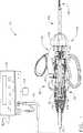
図1は超音波トランスデューサ82、ハンド・ピース・ハウジング20、および本発明によるクランプ式凝固装置120と共に超音波信号発生器15を備えている超音波システム10を示している図である。このクランプ式凝固装置120は切開式または腹腔鏡式の手術において使用可能である。超音波トランスデューサ82は「ランジュバァン・スタック(Langevin stack)」として知られており、一般にトランスダクション部分90、第1の共振器またはエンド−ベル92、および第2の共振器またはフォア−ベル94、および補助部品を備えている。この超音波トランスデューサ82は後に詳述するようにシステム波長の1/2の整数倍の長さ(nλ/2)であることが好ましい。音響組立体80は上記の超音波トランスデューサ82、取付部材36、速度トランスフォーマ64および表面部分95を備えている。
【0016】
エンド−ベル92の先端部はトランスダクション部分90の基端部に接続しており、フォア−ベル94の基端部はトランスダクション部分90の先端部に接続している。フォア−ベル94およびエンド−ベル92はトランスダクション部分90の厚さ、エンド−ベル92およびフォア−ベル94を製造するために使用されている材料の密度および弾性率、および超音波トランスデューサ82の共振振動数を含む多数の変数により決定される一定の長さを有している。フォア−ベル94はその基端部からその先端部にかけて内側にテーパー状にして速度トランスフォーマ64として超音波振動の振幅を増幅可能にすることができ、あるいは、増幅作用を有していなくてもよい。
【0017】
圧電変換素子100は、例えば、ジルコン酸−チタン酸鉛、メタ−ニオブ酸鉛、チタン酸鉛、またはその他の圧電変換性の結晶材料を含む任意の適当な材料により製造できる。正電極96、負電極98、および圧電変換素子100はそれぞれその中心を貫通している中ぐり穴を有している。さらに、正電極96および負電極98はそれぞれ電線102および電線104に電気的に連結されている。各電線102および電線104はケーブル25の中に包まれていて、超音波システム10における超音波信号発生器15に電気的に接続可能である。
【0018】
音響組立体80の超音波トランスデューサ82は超音波信号発生器15からの電気的信号を機械的なエネルギーに変換し、このエネルギーが超音波トランスデューサ82およびエンド−エフェクター180の超音波周波数における主に長手方向の振動動作を生じる。適当な発生器がオハイオ州、シンシナティーのEthicon Endo-Surgery社からモデル番号GEN01として入手可能である。この音響組立体80が励起すると、振動動作の定在波が当該音響組立体80の中に発生する。さらに、この音響組立体80に沿う任意点における振動動作の振幅はその振動動作を測定する音響組立体80に沿う場所により決まる。この振動動作の定在波における最小位置またはゼロ交叉位置は節部(node)(すなわち、動作が通常において最小である)として一般的に呼ばれており、この定在波における絶対値の最大位置またはピーク位置は一般に波腹部(anti-node)として呼ばれている。また、波腹部とこれに最も近い節部との間の距離は1/4波長(λ/4)である。
【0019】
各電線102および電線104は電気的な信号を超音波信号発生器15から正電極96および負電極98にそれぞれ伝達する。圧電変換素子100はフット・スイッチ118に応じて超音波信号発生器15から供給される電気的な信号により励起されて音響学的な定在波を音響組立体80の中に生じる。すなわち、この電気的な信号は各圧電変換素子100において繰り返し状態の小さな変位の形態で乱動を引き起こすことにより大きな圧縮力をこの材料の中に生じる。つまり、この繰り返し状態の小さな変位により各圧電変換素子100がその電圧勾配の軸に沿って連続的な様式で膨張および収縮することにより、超音波エネルギーの長手方向の波が生じる。この超音波エネルギーが音響組立体80を介してエンド−エフェクター180に伝達される。
【0020】
上記の音響組立体80がエンド−エフェクター180にエネルギーを供給するために、この音響組立体80における全ての部品が上記のクランプ式凝固装置120における超音波的に活性な各部分に音響学的に連結されている必要がある。例えば、超音波トランスデューサ82の先端部をスタッド50等のねじ付きの接続手段により超音波導波管179の基端部に表面部分95において音響学的に連結することが可能である。
【0021】
また、上記の音響組立体80における各部品はその任意の組立体の長さが1/2波長の整数倍(nλ/2)であるように音響学的に同調されていることが好ましく、この場合の波長λは所定の波長または音響組立体80の動作用の長手方向に沿う振動の駆動周波数fdであり、nは正の整数である。なお、上記の音響組立体80は各音響要素の任意の適当な配列構成を含むことが可能である。
【0022】
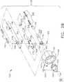
次に図2Aおよび図2Bにおいて、本発明による外科システム10におけるクランプ式凝固装置120が示されている。好ましくは、このクランプ式凝固装置120は1個のユニットとして上記の音響組立体80に対して着脱される。好ましくは、このクランプ式凝固装置120の基端部は図1に示されているように音響組立体80の先端側表面部分95に音響学的に連結されている。なお、このクランプ式凝固装置120が任意の適当な手段により音響組立体80に連結可能であることが認識されると考える。
【0023】
好ましくは、上記のクランプ凝固装置120は器具ハウジング130、および細長い部材150を備えている。この細長い部材150は以下に詳述するように器具ハウジング130に対して選択的に回転できる。器具ハウジング130は旋回式のハンドル部分136、および左側シュラウド134および右側シュラウド138にそれぞれ連結されている固定式のハンドル132Aおよびハンドル132Bを備えている。
【0024】
右側シュラウド138は左側シュラウド134においてスナップ嵌めすることに適合している。好ましくは、この右側シュラウド138は当該右側シュラウド138に形成されている内側に対向している複数のプロング70により左側シュラウド134に連結されている。これら複数のプロング70は左側シュラウド134の中に形成されている対応する各穴または孔140の中に係合するように配列されている。左側シュラウド134を右側シュラウド138に取り付ける際に、これらの間に、後に詳述するような指定機構255等の種々の部品に適合する一定のキャビティが形成される。
【0025】
上記のクランプ式凝固装置120における左側シュラウド134および右側シュラウド138はポリカーボネートにより製造されることが好ましい。なお、これらの構成部品は本発明の趣旨および範囲から逸脱することなく任意の適当な材料により作成することが可能であると考えられる。
【0026】
指定機構255は上記の器具ハウジング130におけるキャビティの中に配置されている。好ましくは、この指定機構255は内側チューブ170に連結または取り付けられていて、ハンドル部分136の移動を内側チューブ170の線形動作に変換してクランプ・アーム組立体300を開閉する。すなわち、旋回式のハンドル部分136が固定式のハンドル部分130の方向に移動すると、指定機構255が内側チューブ170を後方に摺動させてクランプ・アーム組立体300を閉じた状態に旋回させる。また、旋回式のハンドル部分136が上記と反対の方向に移動すると、指定機構255が内側チューブ170を上記と反対の方向、すなわち、前方に移動するように摺動して、クランプ・アーム組立体300をその開口した状態に旋回させる。
【0027】
上記の指定機構255は細長い部材150を器具ハウジング130に対してその長手軸の回りに回転可能にするためのラチェット機構も備えている。この細長い部材150の回転により、クランプ・アーム300が選択された所望の角度位置まで回転可能になる。上記の指定機構255は好ましくは管状カラー260およびヨーク280を備えている。
【0028】
上記の指定機構255の管状カラー260は好ましくは内側チューブ170の基端部上にスナップ嵌めされていて、反対側の開口部168の中にキー係合している。この管状カラー260は好ましくはポリエーテルイミドにより製造されている。なお、この管状カラー260は任意の適当な材料により構成することができる。
【0029】
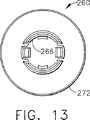
上記の管状カラー260は図11乃至図13にさらに詳細に示されている。好ましくは、この管状カラー260は拡大部分262、およびその中に貫通しているボア(中ぐり穴)266を有している。この拡大部分262は好ましくは管状カラー260の周縁部の周囲に形成されていて溝部268を形成しているリング272を備えている。この溝部268は複数のデテントまたは歯部269を有しており、これらの歯部269は上記の細長い部材150がその長手軸の回りに回転する時に当該細長い部材150を異なる回転位置に保持するために作用する。好ましくは、溝部268は12個のラチェット歯部を有していて、約30度の12個の等角度の増加分で上記の細長い部分を回転可能にしている。なお、上記の管状カラー260は任意数の歯状の部材を有することができる。また、これらの歯状の部材が本発明の範囲および趣旨から逸脱することなく管状カラー260の任意の適当な部分に配置可能であることが認識されると考える。
【0030】
次に図2A乃至図4に戻り、上記旋回式のハンドル部分136は親指用のループ142、第1の穴124、および第2の穴126を有している。ピボット・ピン153がハンドル部分136の第1の穴124の中に配置されていて、図3において矢印121により示されているような旋回を可能にしている。旋回式のハンドル部分136の親指用のループ142が器具ハウジング130から離間して矢印121の方向に移動すると、リンク128が前方方向の一定の力をヨーク280に加えることにより、ヨーク280が前方に移動する。リンク128はピン129により旋回式のハンドル部分136に接続されており、さらに、このリンク128はピン127により基部284に接続されている。
【0031】
次に図2Aに戻り、ヨーク280は一般に保持または支持部材282および基部284を有している。この支持部材282は好ましくは半円形であり、上記管状カラー260の歯部269に対して係合するために内側に延出している一対の対向している爪286を有している。なお、これらの爪286は本発明の趣旨および範囲から逸脱することなく管状カラー260の歯部269に対する係合のためにヨーク280の任意の適当な部分に配置可能であると考えられる。また、このヨーク280が任意数のラチェット・アームを有し得ることも認識されると考える。
【0032】
上記のヨーク280は図19乃至図22にさらに詳細に示されている。旋回式のハンドル部分136は好ましくはヨーク280の基部284におけるスロット147の中に部分的に配置されている。この基部284は基部開口部287、アクチュエータ移動停止部290、および基部ピン−ホール288を有している。上記のピボット・ピン153は基部開口部287の中を通して配置されている。ヨーク280における各爪286は管状カラー260を介して内側チューブ170に開口力を伝達し、これにより、クランプ・アーム組立体が開口する。
【0033】
上記のクランプ式凝固装置120におけるヨーク280は好ましくはポリカーボネートにより製造されている。また、このヨーク280はABS、ナイロン、またはポリエーテルイミド等の別のプラスチック材料を含む種々の材料により作成することも可能である。さらに、このヨーク280は本発明の趣旨および範囲から逸脱することなく任意の適当な材料により構成可能であると考えられる。
【0034】
図3および図4に示されているように、ヨーク280は旋回式のハンドル部分136が器具ハウジング130の方向に移動する時にクランプ・アーム組立体300に一定の閉鎖力を伝達する。アクチュエータ移動停止部290は旋回式のハンドル部分136のストロークの底部においてピボット・ピン153に接触することにより、この旋回式のハンドル部分136のさらなる移動、すなわち過剰移動を阻止する。ヨーク280の各爪286はワッシャー151、力制限スプリング155、およびカラー・キャップ152を介して管状カラー260に力を伝達する。カラー・キャップ152はワッシャー151および力制限スプリング155が拡大部分262よりも基端側の管状カラー260上に組立てられた後に管状カラー260に強固に取り付けられる。このカラー・キャップ152は図5および図6にさらに詳細に示されている。また、力制限スプリング155は図7および図8にさらに詳細に示されており、ワッシャー151は図9および図10にさらに詳細に示されている。ワッシャー151の厚さはクランプ式凝固装置120の設計または製造中に調節されて、力制限スプリング155の予荷重を変更することができる。カラー・キャップ152は超音波溶接により管状カラー260に取り付けられるが、圧入、スナップ嵌め、または接着剤による取り付けが可能である。
【0035】
図5乃至図10において、管状カラー260、ワッシャー151、力制限スプリング155、およびカラー・キャップ152は力制限用の特徴部分をクランプ・アーム組立体300に備えている。旋回式のハンドル部分136が器具ハウジング130に向かって移動すると、クランプ・アーム組立体300は超音波ブレード88に向かって回転する。超音波切断および止血の両方を行うために、クランプ・アーム組立体300の最大力を0.5ポンド乃至3.0ポンド(0.227kg乃至1.362kg)に制限することが望ましい。
【0036】
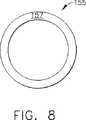
図5および図6はスプリング表面158を含むカラー・キャップ152を示している図である。図7および図8はキャップ表面部分156、ワッシャー表面部分157、および複数のスプリング要素159を含む力制限スプリング155を示している図である。この力制限スプリング155はそのスプリング要素159の形状によりウェーブ・スプリング(wave spring)として当該技術分野において説明されている。このようなウェーブ・スプリングを力制限スプリング155において使用することは、このスプリングが超音波外科器具の諸用途に良好に適合している小形の物理的寸法において高いばね率を示し、この場合に、その中心領域が超音波導波管179のために開口状態であるという理由により、有利である。力制限スプリング155はカラー・キャップ152のスプリング表面部分158とワッシャー151のスプリング面部165との間においてバイアス力を受けている。ワッシャー151はクランプ式凝固装置120(図2乃至図4参照)の組み立て後にヨーク280の各爪286に接触する爪面部167(図9および図10)を有している。
【0037】
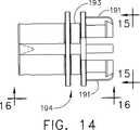
次に、図2A、図2Bおよび図14乃至図18において、回転ノブ190が上記の細長い部材150を回転するために当該細長い部材150に取り付けられていて、管状カラー260がヨーク280に対して回転するようになっている。この回転ノブ190はポリエーテルイミド、ナイロン等の別のプラスチック材料、またはその他の任意の適当な材料を含む種々の材料により作成することも可能である。
【0038】
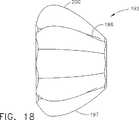
好ましくは、上記の回転ノブ190は拡大部分または外側ノブ192、内側ノブ194、およびこれらを貫通している軸方向のボア196を有している。内側ノブ194は外側ノブ192のキーウェイ189に協同的に取り付けるためのキー191を有している。外側ノブ192は交互に置かれている長手方向に沿う隆起部197および溝部198を有しており、これらは外科医による回転ノブ190および細長い部材150の配向を容易にする。この回転ノブ190の軸方向のボア196は細長い部材150の基端部上に適当に嵌合するように構成されている。
【0039】
内側ノブ194は器具ハウジング130の先端部における開口部139の中に延在している。この内側ノブ194は当該内側ノブ194を上記開口部139の中に回転可能に取り付けるためのチャンネル193を有している。さらに、上記の回転可能なノブ190の内側ノブ194は一対の対向している穴199を有している。これらの対向している各穴199は後に説明するような細長い部材150を貫通している通路195の一部分として整合されている。
【0040】
例えば、ピン163等の連結部材を上記通路195における対向している各穴199の中に配置できる。このピン163は、例えば、ハウジング130内のリブの間に捕捉するか、シリコーンまたはシアノアクリレート等の接着剤を含む任意の適当な手段により細長い部材150の通路195の中に保持できる。このピン163は細長い部材150を回転するために回転ノブ190から細長い部材150に回転トルクを供給することを可能にする。
【0041】
回転ノブ190を回転する場合に、管状カラー260の歯部269がヨーク280の対応する各爪286に係合して僅かに乗り上がる。これらの爪286が歯部269上に乗り上がると、ヨーク280の支持部材282が外側に偏向して各爪286が管状カラー260の歯部269の上を摺動して通過することを可能にする。
【0042】
実施形態の一例において、管状カラー260の歯部269は傾斜部または隆起部として構成されており、ヨーク280の各爪286はポスト部として構成されている。また、これらの管状カラー260の歯部269およびヨーク280の各爪286を逆にして、管状カラー260の歯部269をポスト部とし、ヨーク280の各爪286を傾斜部または隆起部とすることもできる。なお、上記の歯部269を細長い部材150の周縁部に一体に形成するか直接的に連結することも可能であると考えられる。さらに、上記の歯部269および各爪286は、本発明の趣旨および範囲から逸脱することなく、協同的な突出部分、隆起部分、カム面、ラチェット状の歯部、のこ歯部、隆起部、フランジ、または上記細長い部材150を選択的な角度位置に指定可能にするように協同作用するその他の類似手段にすることができることが認識されると考える。
【0043】
図2Bに示されているように、上記のクランプ式凝固装置120における細長い部材150は器具ハウジング130から延出している。図2B乃至図4に示されているように、細長い部材150は好ましくは外側部材または外側チューブ160、内側部材または内側チューブ170、および伝達部品または超音波導波管179を有している。
【0044】
上記の細長い部材150の外側チューブ160は好ましくはハブ162、管状部材164、およびこれらを貫通している長手方向の開口部または孔166を有している。また、この外側チューブ160は好ましくは実質的に円形の断面を有しており、ステンレス・スチールにより製造可能である。なお、この外側チューブ160が任意の適当な材料により構成可能であり、任意の適当な断面形状を有し得ることが認識されると考える。
【0045】
上記の外側チューブ160のハブ162は好ましくは管状部材164よりも大きい直径を有している。このハブ162はピン163を受容して当該ハブ162を回転ノブ190に対して連結可能にするための一対のチューブ穴161を有している。この結果、外側チューブ160は回転ノブ190が回転または回動する時に回転する。
【0046】
外側チューブ160のハブ162はさらに上記ハブ162の反対側の各面部にレンチ・フラット部169を有している。これらのレンチ・フラット部169は好ましくはハブ162の先端部の近くに形成されている。また、これらのレンチ・フラット部169はハブ162に対してトルク・レンチによりトルクを供給して超音波導波管179を音響組立体80のスタッド50に固定することを可能にする。例えば、本明細書に参考文献として含まれる米国特許第5,059,210号および同第5,057,119号はハンド・ピース組立体における取付装置に対して伝達部品を着脱するためのトルク・レンチを開示している。
【0047】
上記の外側チューブ160における管状部材164の先端部に、例えば、組織の把持、組織の切断等のような種々の作業を行うためのエンド−エフェクター180が配置されている。なお、このエンド−エフェクター180が任意の適当な構成に形成可能であることが考えられる。
【0048】
上記のエンド−エフェクター180およびその構成部品が図23乃至図33においてさらに詳細に示されている。このエンド−エフェクター180は一般に、例えば、組織を把持するため、またはブレード88に対して組織を押圧するための非振動性のクランプ・アーム組立体300を備えている。また、このエンド−エフェクター180は図23および図26においてクランプ開口状態で示されており、クランプ・アーム組立体300は好ましくは外側チューブ160の先端部に旋回可能に取り付けられている。
【0049】
先ず、図23乃至図26において、クランプ・アーム組立体300は好ましくはクランプ・アーム202、あご孔204、第1のポスト部206A、第2のポスト部206B、および組織パッド208を有している。クランプ・アーム202はピボット・ピン207Aおよびピボット・ピン207Bに対して旋回可能に取り付けられていて、親指用のループ142が図3において矢印121により示されている方向に移動する時に図3における矢印122の方向に回転する。旋回式のハンドル部分136を器具ハウジング130に向けて進行させることにより、クランプ・アーム202はピボット・ピン207Aおよびピボット・ピン207Bの回りに旋回して閉鎖状態になる。また、旋回式のハンドル部分136を後退して器具ハウジング130から離間させることにより、クランプ・アーム202が旋回して開口状態になる。
【0050】
クランプ・アーム202は超音波ブレード88とクランプ・アーム組立体300との間に組織を挟むために当該クランプ・アーム202に取り付けられている組織パッド208を有している。この組織パッド208は好ましくは高分子またはその他の柔軟な材料により形成されていて、クランプ・アーム202がその閉鎖状態にある時に超音波ブレード88に係合する。好ましくは、この組織パッド208は、例えば、ポリマー状のポリテトラフルオロエチレン(PTFE)に相当するE. I. Du Pont de Nemours and Companyの商標名であるTEFLON(R)(テフロン(R))のように、一定の低い摩擦係数を有しているが、組織の把持能力を示すために実質的に剛性である材料により形成されている。この組織パッド208は接着剤、好ましくは以下に説明するような機械的な固定構造によりクランプ・アーム202に取り付けることができる。
【0051】
図23、図26および、図28において示されているように、のこ歯部210が組織パッド208のクランプ表面部に形成されていて、超音波ブレード88の軸に対して垂直に延在して、組織をクランプ・アーム202と超音波ブレード88との間において滑らせることなく組織の把持、操作、凝固および切断を可能にしている。
【0052】
組織パッド208は図27乃至図29にさらに詳細に示されている。この組織パッド208はT字形状の突出部212、左側突出面部214、右側突出面部216、上面部218、および下面部219を有している。下面部219は既に説明したのこ歯部210を有している。さらに、組織パッド208は以下に説明するような組み立て中における挿入を容易にするためのベベル状の前端部209を有している。
【0053】
図26において、上記内側チューブ170における管状部材174の先端部は好ましくは当該先端部から延出しているフィンガー部またはフランジ部171を有している。このフランジ部171はクランプ・アーム202の第1のポスト部206Aおよび第2のポスト部206Bをそれぞれ受容するための開口部173Aおよび173B(図示せず)を有している。これにより、細長い部材150の内側チューブ170が軸方向に移動する時に、上記のフランジ部171がクランプ・アーム組立体300の第1のポスト部206Aおよび第2のポスト部206Bに係合しながら前方または後方に移動することによりクランプ・アーム202を開閉する。
【0054】
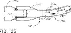
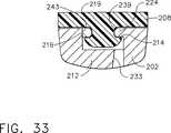
次に、図24、図25および図31乃至図33において、エンド−エフェクター180のクランプ・アーム202がさらに詳細に示されている。クランプ・アーム202はアーム上部228およびアーム下部230、ならびに、直線状部分235および湾曲状部分236を有している。直線状部分235は直線状のT字形スロット226を有している。また、湾曲状部分236は第1の上部穴231、第2の上部穴232、第3の上部穴233、第4の上部穴234、第1の下部切り欠き部241、第2の下部切り欠き部242、第3の下部切り欠き部243、第4の切り欠き部244、第1の棚部221、第2の棚部222、第3の棚部223、第4の棚部224、および第5の棚部225を有している。
【0055】
上記の穴231はアーム上部228からクランプ・アーム202を介して第2の棚部222まで延在している。また、上記の穴232はアーム上部228からクランプ・アーム202を介して第3の棚部223まで延在している。また、上記の穴233はアーム上部228からクランプ・アーム202を介して第4の棚部224まで延在している。さらに、上記の穴234はアーム上部228からクランプ・アーム202を介して第5の棚部225まで延在している。これらの各穴231乃至穴234および各棚部221乃至棚部225の配列構成によりクランプ・アーム202が上記の直線状部分235および湾曲状部分236の両方を備えることが可能になると共に、例えば、金属射出成形(MIM)等の方法により成形可能になる。クランプ・アーム202は上記のMIM法を利用することによりステンレス・スチールまたはその他の適当な金属により作成できる。
【0056】
図30および図31において、組織パッド208におけるT字形の突出部212はクランプ・アーム202のT字形スロット226の中に挿入可能である。クランプ・アーム202は、組織パッド208が、例えば、射出成形、機械加工、または押出成形等により直線状の部品として製造可能になるように設計されている。クランプ・アーム202においてその直線状のT字形スロット226の中に挿入されて湾曲状部分236の中に進行する時に、ベベル状の前端部209が組織パッド208の屈曲を容易にしてクランプ・アーム202の曲率に一致させる。さらに、各穴231乃至穴234および各棚部221乃至棚部225の配列構成により、クランプ・アーム202が組織パッド208を屈曲して保持することが可能になる。
【0057】
図32および図33はクランプ・アーム202が当該クランプ・アーム202の湾曲状部分236に対して一致している組織パッド208の屈曲状態を維持しながら組織パッド208を保持する方法を示している図である。図32に示されているように、第3の棚部223は右側突出面部216に接触して接触エッジ部238を形成しているが、左側の突出面部214はこの位置において支持されていない。一方、図33に示されている、先端側の位置においては、第4の棚部224が左側突出面部214に接触して接触エッジ部239を形成しているが、右側の突出面部216はこの位置において支持されていない。
【0058】
次に、図2に戻り、細長い部材150の内側チューブ170は外側チューブ160の開口部166の中に適当に嵌合している。この内側チューブ170は好ましくは内側ハブ172、管状部材174、外周溝176、一対の対向している開口部178、一対の対向している開口部168、およびこれらを貫通している長手方向の開口部または孔175を有している。この内側チューブ170は好ましくは実質的に円形の断面を有しており、ステンレス・スチールにより製造可能である。なお、この内側チューブ170が任意の適当な材料により構成可能であり、任意の適当な形状にできることが認識されると考える。
【0059】
上記の内側チューブ170における内側ハブ172は好ましくは上記の管状部材174よりも大きい直径を有している。また、この内側ハブ172における一対の対向している開口部178は内側ハブ172がピン163を受容可能にして、内側チューブ170および超音波導波管179が既に説明したように当該超音波導波管179をスタッド50に取り付けるためのトルクを伝達可能にしている。O−リング220は好ましくは内側ハブ172の外周溝176の中に配置されている。
【0060】
上記の細長い部材150における超音波導波管179は内側チューブ170の孔175の中に延在している。この超音波導波管179は好ましくは実質的に半柔軟性である。なお、この超音波導波管179が実質的に剛性であってもよく、また、柔軟性のワイヤ部材でもよいことが認識されると考える。これにより、超音波振動が超音波導波管179に沿って長手方向に伝達されて超音波ブレード88を振動させる。
【0061】
上記の超音波導波管179は、例えば、システム波長の1/2の整数倍(nλ/2)に実質的に等しい長さを有することができる。この超音波導波管179は好ましくはチタン合金(すなわち、Ti−6Al−4V)またはアルミニウム合金等の超音波エネルギーを効率的に伝搬する材料により構成されている中実コアの軸材により製造できる。なお、この超音波導波管179は任意の別の適当な材料により製造することも可能であることが考えられる。また、この超音波導波管179は当該技術分野において周知であるように上記の超音波ブレード88に伝達される機械的な振動を増幅することも可能である。
【0062】
図2に示すように、超音波導波管179は当該超音波導波管179の周縁部の周囲における種々の位置に配置されている1個以上の安定化用のシリコーン・リングまたは制振シース110(1個が示されている)を有することができる。この制振シース110は不所望な振動を制振して内側チューブ170からの超音波エネルギーを分離することにより、この超音波エネルギーを最大効率で超音波ブレード88の先端部まで長手方向に確実に伝達する。この減衰シース110は、例えば、本明細書に参考文献として含まれる米国特許出願第08/808,652号に記載されている減衰シースのように締り嵌めにより超音波導波管179に固定できる。
【0063】
さらに、図2において、超音波導波管179は一般に第1の部分182、第2の部分184、および第3の部分186を有している。この超音波導波管179の第1の部分182は当該超音波導波管179の基端部から先端側に延在している。この第1の部分182が実質的に連続的な一定の断面寸法を有している。
【0064】
上記第1の部分182は好ましくはその中を貫通している少なくとも1個の半径方向の穴188を有している。この導波管の穴188は超音波導波管179の軸に対して実質的に垂直に延在している。この導波管の穴188は好ましくは節部に配置されているが、超音波導波管179に沿う任意のその他の適当な位置に配置することも可能である。なお、この導波管の穴188が任意の適当な深さを有することができ、任意の適当な形状を有し得ることが認識されると考える。
【0065】
上記の第1の部分182における導波管の穴188はピン163を受容するために上記ハブ172において対向している各開口部178およびハブ162における外側チューブの各穴161に整合されている。ピン163は細長い部材150を回転するために回転トルクが回転ノブ190から超音波導波管179に加えられることを可能にする。細長い部材150における通路195は対向している各開口部178、外側チューブの各穴161、導波管の穴188、および対向している各穴199を含む。
【0066】
上記の超音波導波管179における第2の部分184は第1の部分182から先端側に延在している。この第2の部分184は実質的に連続的な一定の断面寸法を有している。この第2の部分184の直径は上記第1の部分182の直径よりも小さい。これにより、超音波エネルギーは超音波導波管179における第1の部分182から第2の部分184に伝達され、この第2の部分184において狭められている部分により当該部分を通過する超音波エネルギーの振幅が増幅される。
【0067】
さらに、上記の第3の部分186が上記第2の部分184の先端部から先端側に延在している。この第3の部分186は実質的に連続的な一定の断面寸法を有している。また、この第3の部分186はその長さに沿って変化している小さい直径を有することも可能である。この第3の部分は好ましくは当該第3の部分186の外周縁部の周囲に形成されているシール187を有している。これにより、超音波エネルギーは超音波導波管179における第2の部分184から上記第3の部分186の中に伝達され、この第3の部分186において狭められている部分により当該部分を通過する超音波エネルギーの振幅が増幅される。
【0068】
上記の第3の部分186はその外周部分に形成されている複数の溝部またはノッチ部(図示せず)を有することができる。これらの溝部は製造中において制振シース110を備え付けるための整合指示手段として作用するために超音波導波管179の各節部または当該超音波導波管179に沿う任意の別の適当な位置に配置することが可能である。
【0069】
さらに、図2において、上記外科器具150における制振シース110は超音波導波管179の少なくとも一部分を囲っている。この制振シース110は超音波導波管179の周囲に配置されて、動作中における超音波導波管179の横方向の側面から側面に到る振動を制振または制限することができる。この制振シース110は好ましくは超音波導波管179の第2の部分184の一部を囲っている。なお、この制振シース110が超音波導波管179における任意の適当な部分の周囲に配置可能であることも考えられる。また、この制振シース110は好ましくは横方向の振動における少なくとも1個の波腹部、さらに好ましくは横方向の振動における複数の波腹部において延在している。さらに、この制振シース110は好ましくは実質的に円形の断面を有している。なお、この制振シース110が超音波導波管179上に嵌合する任意の適当な形状を有することができ、任意の適当な長さを有し得ることが認識されると考える。
【0070】
制振シース110は好ましくは超音波導波管179に軽く接触して超音波導波管179からの不所望な超音波エネルギーを吸収する。この制振シース110は55,500Hzの長手方向の周波数ならびにそれ以上およびそれ以下の周波数に付随する不所望な横方向の振動を含む超音波導波管179の軸方向以外の振動の振幅を減少する。
【0071】
上記の制振シース110は超音波導波管179の軸方向の動作すなわち長手方向の振動によるエネルギーの消失を最少にするために、好ましくは一定の低摩擦係数を有する高分子材料により構成されている。この高分子材料は好ましくはフロウラ−エチレン・プロペン(floura-ethylene propene)(FEP)であり、この材料はガンマ放射線による滅菌処理における崩壊に対して耐性を有している。なお、上記の制振シース110が、例えば、PTFE等の任意の適当な材料により製造可能であることが認識されると考える。
【0072】
上記の制振シース110は好ましくはこれを貫通する開口部、および長手方向のスリット111を有している。この制振シース110のスリット111は制振シース110がいずれの端部からも超音波導波管179の上に組み合わせられることを可能にしている。なお、この制振シース110が当該制振シース110を超音波導波管179の上に嵌合可能にする任意の適当な構成を有し得ることが認識されると考える。例えば、この制振シース110はコイルとしてまたは螺旋状に形成することができ、あるいは長手方向および/または外周方向のスリットまたはスロットの種々のパターンを有することができる。さらに、この制振シース110がスリット111無しで製造可能であること、および超音波導波管179が制振シース110の中に嵌合するための2個以上の部品により製造可能であることも考えられる。
【0073】
上記の超音波導波管179が任意の適当な断面寸法を有し得ることが認識されると考える。例えば、この超音波導波管179は実質的に均一な断面を有していてもよく、また、この超音波導波管179は種々の部分においてテーパー状であってもよく、あるいはその全長にわたってテーパー状であってもよい。
【0074】
また、上記の超音波導波管179は当業界において周知のように当該超音波導波管179を介して超音波ブレード88に伝達される機械的な振動を増幅することもできる。さらに、この超音波導波管179は当該超音波導波管179に沿う長手方向の振動の利得を制御するための特徴部分および当該超音波導波管179をシステムの共振振動数に同調するための特徴部分を有することができる。
【0075】
上記の超音波導波管179における第3の部分186の基端部は好ましくは波腹部の近くにおいて内部のねじ付き接続手段により上記第2の部分184の先端部に連結することができる。なお、この第3の部分186が溶接接合等の任意の適当な手段により上記第2の部分184に取り付け可能であると考えられる。この第3の部分186は超音波ブレード88を含む。この超音波ブレード88は超音波導波管179から分離可能にすることができるが、この超音波ブレード88および超音波導波管179は単一ユニットとして形成されていることが好ましい。
【0076】
上記の超音波ブレード88はシステム波長の1/2の整数倍(nλ/2)に実質的に等しい長さを有することができる。また、この超音波ブレード88の先端部は当該先端部における最大の長手方向の偏位を行うために波腹部の近くに配置することができる。これにより、上記のトランスデューサ組立体が励起されると、超音波ブレード88の先端部は所定の振動周波数において、例えば、約10ミクロン乃至500ミクロンのピーク−トゥ−ピーク動作、好ましくは約30ミクロン乃至150ミクロンの範囲内で移動するように構成される。
【0077】
上記の超音波ブレード88は好ましくはチタン合金(すなわち、Ti−6Al−4V)またはアルミニウム合金等の超音波エネルギーを伝搬する材料により構成されている中実コアの軸材により作成されている。なお、この超音波ブレード88が任意の別の適当な材料により製造できることが認識されると考える。さらに、この超音波ブレード88がエネルギーの供給および所望の組織作用を改善するための表面処理を有し得ることも考えられる。例えば、この超音波ブレード88は凝固性および組織の切断能力を高めるため、および/または、組織および血液のエンド−エフェクターに対する付着性を減少するために、微細仕上げ、コーティング処理、めっき処理、エッチング処理、グリット・ブラスト仕上げ、粗面化またはスコア処理することができる。加えて、この超音波ブレード88はその諸特性を高めるために鋭利化または付形処理することができる。例えば、この超音波ブレード88はブレード形状、フック形状、またはボール形状にすることができる。
【0078】
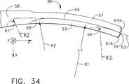
図34、図35および、図36に示すように、本発明による超音波ブレード88の形状は既存の装置よりもさらに均一にクランプした組織に超音波出力を供給する。エンド−エフェクター180はブレード末端部分の改善された可視性を提供するので、外科医はブレード88が切断または凝固されている構造を横切って延在していることを確認できる。このことは特に大血管の縁を確認する場合に重要である。また、この形状は生物学的な諸構造の湾曲部分にさらに似せることによりさらに改善された組織への接近能力も提供する。このブレード88は多数の組織作用、すなわち、クランプ状態の凝固、クランプ状態の切断、把持、背部切断、切開、スポット凝固、末端部分の侵入および末端部分のスコア処理等を行うように設計されている多数のエッジ部分および表面部分を備えている。
【0079】
ブレード88の最先端部分は接線63、すなわち、当該先端部分における湾曲部分に対して接している線に対して垂直な表面部分54を有している。また、2個のすみ肉状の特徴部分61Aおよび特徴部分61Bが各表面部分51,52および54を混合するために使用されており、これによりスポット凝固に利用できる鈍い先端部分が形成されている。また、ブレード88の上部は丸み付けまたは鈍化されていて、当該ブレード88とクランプ・アーム組立体300との間に組織をクランプするための広いエッジ部分または表面部分56を形成している。この表面部分56はクランプ状態での切断処理および凝固処理のために使用されると共に、ブレードの不活性時に組織を操作するためにも使用される。
【0080】
また、下面部はブレード88の底部に沿って狭いエッジ部すなわち鋭いエッジ部55を形成している球面状の切断部分53を有している。このような材料の切断は、例えば、半径R1の円弧状に球面端部のミルを掃引した後にブレード88の底面部58に上記の切断部分を混合するさらに狭い第2の半径R2によりこの切断部分を仕上げすることにより達成できる。上記の半径R1は好ましくは0.5インチ乃至2インチ(1.27cm乃至5.08cm)の範囲内、さらに好ましくは0.9インチ乃至1.1インチ(2.29cm乃至2.79cm)の範囲内、最も好ましくは約1.068インチ(2.713cm)である。また、上記の半径R2は好ましくは0.125インチ乃至0.5インチ(0.318cm乃至1.27cm)、最も好ましくは約0.25インチ(0.64cm)である。この第2の半径R2およびこれに対応するブレード88の底面部58との混合部分はこの混合部分の無い切断状態で停止する場合に比べてその球面状の切断部分の端部に集中する応力を減少する。上記の鋭いエッジ部55は脈管の少ない組織の中の切開および非クランプ状態の切断(背部切断)を容易にする。
【0081】
上記ブレード88の底面部58における球面状の切断部分53は鋭いエッジ部55を形成すると共にブレード88から最小量の材料を除去している。このブレード88の底部における球面状の切断部分53は以下に説明するように一定の角度αを有する鋭いエッジ部55を形成している。この角度αは、例えば、オハイオ州、シンシナティーのEthicon Endo-Surgery社により製造されているLCS-K5のような既存のシャー装置と同様にできる。しかしながら、本発明のブレード88はその一般的な供給力に関して上記の角度αの配向により既存の装置よりも速く切断することができる。既存のシャー装置の場合には、その各エッジ部が対称形であり、その供給力を均等に広げる。一方、本発明の場合の各エッジ部は非対称であって、このエッジ部の非対称性が組織の分離または切断における速度の高さを示す。すなわち、この非対称性は鈍化した形状を維持しながら大きな容量の材料を除去することなく超音波により活性化される時に効果的にさらに鋭いエッジ部を提供することにおいて重要である。また、この非対称形の角度ならびに上記ブレードの湾曲部分は僅かなフック状のまたは楔状の作用により背部切断中にそれ自体で組織に張力を加えるように作用する。
【0082】
超音波ブレード88の鋭いエッジ部55は、表面部分53と底面部58が球面状の切断部分53を受容した後に残された第2の表面部分57との交線により定められる。クランプ・アーム組立体300は、超音波ブレード88に対して旋回移動して当該クランプ・アーム組立体300と超音波ブレード88との間に組織をクランプするために外側チューブ160の先端部に旋回可能に取り付けられている。この結果、内側チューブ170の往復移動により、クランプ・アーム組立体300が円弧状に旋回して、垂直面181が定められる。鋭いエッジ部55における球面状の切断部分53の接線60は、図35に示されているように第2の表面部分57の接線62に対して一定の角度αを定めている。この角度αの二等分線59は、好ましくは上記の垂直面181内に存在せずに、角度βだけずれている。好ましくは、上記球面状の切断部分53の接線60は、垂直面181に対して約5度乃至50度の範囲内で存在している。最も好ましくは、この球面状の切断部分53の接線は、垂直面181から約38.8度で存在している。好ましくは、上記角度αは、約90度乃至150度の範囲内である。最も好ましくは、この角度αは、約121.6度である。
【0083】
図35Aにおいて、本発明の別の実施形態が非対称な狭いエッジ部を伴って示されている。鋭いエッジ部55Aにおける球面状の切断部分53Aの接線60Aは図35Aに示されているように第2の表面部分57Aの接線62Aに対して一定の角度αAを定めている。この角度αAの二等分線59Aは好ましくは垂直平面181A内に存在しておらず、一定の角度βAだけずれている。
【0084】
上記の超音波ブレード88の設計における湾曲状の形状はさらに組織をこのブレードに対してクランプした場合にこの組織に対するさらに均一な分布状態のエネルギー供給を生じる。このような均一なエネルギー供給はエンド−エフェクター180の長さに沿う一定の組織作用(熱的および横断面方向の作用)を達成するので望ましい。ブレード88における最先端の15ミリメートルの部分は作用部分であり、一定の組織作用を達成するために用いられる。後に詳述するように、上記湾曲状のシャー・ブレード88に沿う各場所に対応する変位ベクトルは、既存の器具に優る本発明の種々の改善により、図34および図35において示されているx−y平面に主として存在しているそれぞれの方向を有する。それゆえ、このブレード88の動作はクランプ・アーム組立体300からのクランプ力の方向に対して垂直な一定の平面(x−y平面)内に存在している。
【0085】
一般に、直線状の対称形の超音波ブレードは図34および図35におけるx軸で示される長手軸に沿って存在している末端部分の偏位を有する。また、横方向の動作はこの動作が内側チューブ170内における不所望な熱の発生を引き起こすために通常において望ましくない。そこで、既に本明細書に参考文献として含まれている米国特許出願第09/106,686号において記載されているような湾曲状のエンド−エフェクターを含む機能的な非対称形の部分を超音波ブレードに付加すると、この機能的な非対称形の部分が超音波導波管内に非平衡作用の部分を形成する。この非平衡部分が適正でない場合には、不所望な熱、ノイズ、および損なわれている組織作用が生じる。上記の米国特許出願第09/106,686号は平衡化用の非対称部分よりも基端側において平衡化されている超音波ブレードを提供する方法を教示しているが、そのエンド−エフェクターの先端部分は少なくとも2方向の軸における偏位を有している。そこで、このエンド−エフェクターが湾曲状のエンド−エフェクターのように単一平面の機能的な非対称部分を有していて、そのブレードがそれ以外において対称形であれば、その偏位はその最先端部分において一定の平面内に存在することになる。
【0086】
多くの場合において、任意の超音波ブレード88のz軸方向における偏位を最小にすることが望ましい。このz軸方向における超音波ブレード88の偏位はシステムを非効率的にして、不所望な発熱、出力損失、およびノイズ発生の可能性を生じる。エンド−エフェクター180におけるz軸方向の超音波ブレード88の偏位はこの超音波ブレード88とクランプ・アーム組立体300との間に存在している組織に対して当該超音波ブレード88による衝撃を与える。そこで、図34および図35に示されているx−y平面に対する超音波ブレード88の偏位を制限することが望ましい。このことは超音波ブレード88が衝撃を与えることなく当該超音波ブレード88とクランプ・アーム組立体300との間に存在している組織を擦ることを可能にし、これにより組織の発熱が最適化されて、最適な凝固処理が行える。このようなエンド−エフェクター180よりも基端側の部分および超音波ブレード88内の部分の両方におけるz軸方向の偏位を最小にすることは球面状の切断部分53の適当な選択により達成できる。
【0087】
しかしながら、図34乃至図36に示されているような超音波ブレード88を含む多数の機能的な非対称部分を有する超音波ブレード88を伴う超音波エンド−エフェクター180は適正に平衡化されていなければx,yおよびzの3個の全ての軸において末端部分の偏位を含む傾向を本質的に有している。例えば、図34に示されているような超音波ブレード88はその先端部においてy軸方向に湾曲している。この湾曲部分はエンド−エフェクター180よりも基端側において平衡化されているが、当該湾曲部分は超音波ブレード88がその活性化時にx軸およびy軸の両方の方向においてそれぞれの偏位を有するように作用する。また、上記の球面状の切断部分53を加えることによりさらに別の量の非対称部分が超音波ブレード88に加えられ、適正でない場合には全ての3個の軸において末端部分の偏位が生じて、超音波導波管179におけるz軸方向の非平衡作用も生じてその効率が低下する。
【0088】
そこで、超音波導波管179におけるz軸方向の偏位を最小にするために最適化された機能的な非対称部分を供給することにより、その機能的な非対称部分よりも基端側のz軸方向の末端部分における偏位を最小にすることが可能になり、改善された組織作用により効率を最大にできる。図34に示すように、球面状の切断部分53は最先端部から任意の位置まで超音波ブレード88内に基端側に延在することができる。例えば、図34は超音波ブレード88内に延在する球面状の切断部分53の場合の第1の位置66、第2の位置67、および第3の位置68を示している。
【0089】
以下の表1は、第3位置66、第2位置67、および、第1位置68として図34に示されているような超音波ブレード88のための可能な3つの球面状切断部分長さを示す。表1の横列は、超音波ブレード88へのカット長さに対応し、表1の縦列は、各軸に沿ったカット長さ毎のバランス状態および偏位に対応する。表1から分かるように、球面状カット部53を第1位置68に対応する長さにすることにより、機能的非対称部の近位側のz軸方向偏位が最小になる。機能的非対称部の近位側のz軸方向偏位が15%以下になるように超音波ブレード88を平衡化することが好ましい。さらには、機能的非対称部の近位側のz軸方向偏位が5%以下になるように超音波ブレード88を平衡化することがより好ましい。好ましくは、クランプ式凝固装置120は、(空気の負荷のみが掛る)空気中での作動時にバランスが保たれるように設計される。
【0090】
表1で、エンド−エフェクター88のクランプ器具の正規化された偏位率(%z)は、完全に閉じた位置のクランプ・アームに対して垂直な方向の偏位量を計測し、この偏位量を先端最大振動偏位量(先端一次振動偏位量(primary tip vibration excursion)とも呼ぶ)で割り算した後、被除数に100を掛けることにより算出される。先端一次振動偏位は、作動している超音波ブレード88の最も遠位の一点により形成される楕円または楕円体の主軸の大きさである。上記偏位の計測は、超音波外科システムの基本的な出力特性の測定および表明(Measurement and Declaration of the Basic Output Characteristics)と題するIEC国際規格61847においてさらに詳細に説明されており、参照により本明細書に組み込まれる。超音波ブレード88または超音波導波管179の正規化された偏位率(%x,%y,%z)は、先端二次振動偏位量(secondary tip vibration excursion)を計測し、この偏位量を先端一次振動偏位量で割り算した後、被除数に100を掛けることにより算出される。先端二次振動偏位は、作動している超音波ブレード88の最も遠位の一点により形成される楕円または楕円体の短軸の大きさまたは他の任意軸の大きさである。
【表1】
機能的非対称部を含むブレードによるTi6A14Vにより製造したR1の半径を有する0.946インチ(2.403cm)の長さのブレードにおいて一定範囲の平衡作用を示すための3種類の可能な長さ
次に、図1乃至図4において、上記のクランプ式凝固装置120を音響組立体80に対して着脱するための手順を以下に説明する。医者がクランプ式凝固装置120を使用する準備ができると、この医者はそのクランプ式凝固装置120を音響組立体80に単純に取り付ける。このクランプ式凝固装置120を音響組立体80に取り付けるためには、スタッド50の先端部を伝達部品すなわち超音波導波管179の基端部にねじにより接続する。その後、このクランプ式凝固装置120を慣用的なねじ締め方向に手動で回転して、スタッド50と超音波導波管179との間のねじ接合部分をインターロックする。
【0092】
超音波導波管179をスタッド50にねじにより接合した後に、例えば、トルク・レンチのような工具をクランプ式凝固装置120の細長い部材150の上に配置して超音波導波管179をスタッド50に対して締め付ける。この工具は外側チューブ160におけるハブ162のレンチ・フラット部分169に係合して超音波導波管179をスタッド50上に固定するように構成できる。この結果、ハブ162の回転により、超音波導波管179が所望且つ所定のトルクでスタッド50に対して固定されるまで細長い部材150が回転される。なお、上記のトルク・レンチがクランプ式凝固装置120の一部分として、または本明細書に参考文献として含まれる米国特許第5,776,155号に記載されているトルク・レンチのように、ハンド・ピース・ハウジング20の一部分として別に製造可能であることが考えられる。
【0093】
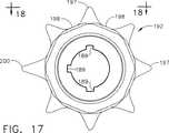
クランプ式凝固装置120を音響組立体80に取り付けた後に、外科医は回転ノブ190を回転して細長い部材150を所望の角度位置に調節することができる。回転ノブ190を回転している時に、管状カラー260の歯部269がヨーク280の各爪286の上を摺動して隣接するノッチ部または谷部の中に入る。この結果、外科医はエンド−エフェクター180を所望の配向に位置決めできる。回転ノブ190は器具ハウジング130とクランプ・アーム202との間の回転方向の関係を指定するための指定手段を組み込むことができる。図17および図18に示されているように、例えば、拡大された隆起部200を利用することにより、回転ノブ190における隆起部197の内の1個を器具ハウジング130に対するクランプ・アーム202の回転方向の位置を指定するために使用できる。なお、拡大された隆起部200の使用と同様に位置を指定するために、色、シンボル、表面模様等の使用を含む別の指定手段を回転ノブ190において用いることも可能であると考えられる。
【0094】
音響組立体80のスタッド50からクランプ式凝固装置120を分離するためには、この外科器具120の細長い部材150上に上記の工具を摺動してこれを反対方向、すなわち、超音波導波管179をスタッド50に対するねじ係合から解除する方向に回転することができる。この工具を回転すると、外側チューブ160のハブ162はトルクがピン163を介して超音波導波管179に加えられることを可能にして、比較的高い係合解除用のトルクが超音波導波管179をそのねじ係合解除の方向に回転するように加えられる。この結果、超音波導波管179はスタッド50から緩み離れる。このようにして超音波導波管179がスタッド50から取り外された後に、クランプ式凝固装置全体が放出可能になる。
【0095】
以上、本発明の好ましい実施形態を本明細書において図示し説明したが、当該技術分野における熟練者においては、これらの各実施形態が例示的な目的のみにより提供されていることが明らかになる。すなわち、この時点において、多数の変形、変更、および置換が本発明から逸脱することなく当該技術分野における熟練者において考え出されるようになる。従って、本発明は本明細書に記載する特許請求の範囲における趣旨および範囲のみにより制限されるべきであると考える。
本発明の新規な特徴は特に本明細書における特許請求の範囲において記載されている。しかしながら、本発明自体は、その構成および動作方法の両方について、そのさらに別の目的および利点と共に、以下の添付図面と共にその詳細な説明を参考にすることにより最良に理解できる。
【図面の簡単な説明】
【図1】 超音波発生器の側面図、超音波トランスデューサの断面図、および本発明によるクランプ式凝固装置の部分断面図を含む超音波外科システムを示している。
【図2A】 本発明によるクランプ式凝固装置の一部分の分解斜視図である。
【図2B】 本発明によるクランプ式凝固装置の一部分の分解斜視図である。
【図3】 開口状態で示されているクランプ・アーム組立体を伴う本発明によるクランプ式凝固装置の部分断面図である。
【図4】 閉鎖状態で示されているクランプ・アーム組立体を伴う本発明によるクランプ式凝固装置の部分断面図である。
【図5】 上記クランプ式凝固装置におけるカラー・キャップの側面図である。
【図6】 上記クランプ式凝固装置におけるカラー・キャップの正面図である。
【図7】 上記クランプ式凝固装置における力制限用スプリングの側面図である。
【図8】 上記クランプ式凝固装置における力制限用スプリングの正面図である。
【図9】 上記クランプ式凝固装置におけるワッシャーの側面図である。
【図10】 上記クランプ式凝固装置におけるワッシャーの正面図である。
【図11】 上記クランプ式凝固装置における管状カラーの側面図である。
【図12】 上記クランプ式凝固装置における管状カラーの後面図である。
【図13】 上記クランプ式凝固装置における管状カラーの正面図である。
【図14】 上記クランプ式凝固装置における内側ノブの側面図である。
【図15】 上記クランプ式凝固装置における内側ノブの正面図である。
【図16】 上記クランプ式凝固装置における内側ノブの下面図である。
【図17】 上記クランプ式凝固装置における外側ノブの後面図である。
【図18】 上記クランプ式凝固装置における外側ノブの上面図である。
【図19】 上記クランプ式凝固装置におけるヨークの上面図である。
【図20】 上記クランプ式凝固装置におけるヨークの側面図である。
【図21】 上記クランプ式凝固装置におけるヨークの正面図である。
【図22】 上記クランプ式凝固装置におけるヨークの斜視図である。
【図23】 上記クランプ式凝固装置におけるエンド−エフェクターの斜視図である。
【図24】 上記クランプ式凝固装置におけるクランプ・アームの上部斜視図である。
【図25】 上記クランプ式凝固装置におけるエンド−エフェクターの上面図である。
【図26】 クランプ・アームが開口状態である上記クランプ式凝固装置におけるエンド−エフェクターの側面図である。
【図27】 上記クランプ式凝固装置における組織パッドの上面図である。
【図28】 上記クランプ式凝固装置における組織パッドの側面図である。
【図29】 上記クランプ式凝固装置における組織パッドの正面図である。
【図30】 上記クランプ式凝固装置における組織パッドの斜視図である。
【図31】 上記クランプ式凝固装置におけるクランプ・アームの下部斜視図である。
【図32】 図31に示されているクランプ・アームの第1の断面図である。
【図33】 図31に示されているクランプ・アームの第2の断面図である。
【図34】 上記クランプ式凝固装置におけるブレードの下面図である。
【図35】 上記クランプ式凝固装置におけるブレードの断面図である。
【図35A】 上記クランプ式凝固装置の別の実施形態におけるブレードの断面図である。
【図36】 上記クランプ式凝固装置におけるエンド−エフェクターの斜視図である。
【符号の説明】
10 超音波システム
15 超音波信号発生器
20 ハンド・ピース・ハウジング
80 音響組立体
82 超音波トランスデューサ
120 クランプ式凝固装置
130 器具ハウジング
150 細長い部材
179 超音波導波管
180 エンド−エフェクター
300 クランプ・アーム組立体[0001]
FIELD OF THE INVENTION The present invention relates generally to ultrasonic surgical instruments, and in particular, a multifunctional curvature having a functional asymmetric portion for use with an ultrasonic surgical instrument to minimize undesired motion. Related to the blade.
[0002]
BACKGROUND OF THE INVENTION This patent application is a co-pending patent application: US patent application Ser. No. 08 / 948,625 filed Oct. 10, 1997, Oct. 10, 1997. No. 08 / 949,133, filed on Jun. 29, 1998 No. 09 / 106,686, No. 09/337, filed Jun. 21, 1999 No. 077, No. 09 / 412,557, No. 09 / 412,996, and No. 09 / 413,225, which are incorporated herein by reference.
[0003]
Ultrasound instruments, including hollow core and solid core instruments, are used for the safe and effective treatment of many medical conditions. Ultrasound instruments, particularly solid core ultrasound instruments, are used to cut and / or coagulate organic tissue using energy in the form of mechanical vibrations that are transmitted to the surgical end-effector at ultrasonic frequencies This is advantageous. Ultrasonic vibration can be used to cut, incise, or cauterize tissue when transmitted to organic tissue at an appropriate energy level and using an appropriate end-effector. Ultrasonic instruments that utilize solid core techniques are particularly advantageous because of the amount of ultrasonic energy that can be transmitted from the ultrasonic transducer through the waveguide to the surgical end-effector. These instruments are particularly suitable for use in minimally invasive procedures, including endoscopic or laparoscopic procedures, where the end-effector reaches the surgical site through the trocar.
[0004]
Ultrasonic vibrations are induced in the surgical end-effector by electrically exciting a transducer that can be comprised of, for example, one or more piezoelectric transducer elements or magnetostrictive elements in the instrument hand piece. Vibrations generated by the transducer portion are transmitted to the surgical end-effector via an ultrasonic waveguide that extends from the transducer portion to the surgical end-effector. These waveguides and end-effectors are designed to resonate at the same frequency as the transducer. Therefore, when the end-effector is attached to the transducer, the overall system frequency remains the same as the transducer itself.
[0005]
The amplitude d of the ultrasonic vibration in the longitudinal direction at the end portion functions as a simple sine wave at the resonance frequency given as follows.
d = Asin (ωt) (Formula 1)
In this formula:
ω = angular frequency equal to 2π times the periodic frequency f,
A = zero-to-peak amplitude.
The longitudinal operating range is defined as peak-to-peak (ptp) amplitude, which is exactly twice the amplitude of the sine wave, ie 2A.
[0006]
Solid core ultrasonic surgical instruments can be divided into two types of devices: single-element end-effector devices and multi-element end-effectors. Single element end-effector devices include instruments such as surgical scalpels and ball coagulators, see, eg, US Pat. No. 5,263,957. While instruments such as those disclosed in US Pat. No. 5,263,957 are known to be quite satisfactory, there are some limitations in their use as well as in other ultrasonic surgical instruments. is there. For example, single element end-effector devices have limited ability to apply pressure from the blade to the tissue when the tissue is soft and gently supported. Sufficient pressure is required to effectively transmit ultrasonic energy to the tissue. If the tissue cannot be reliably captured in this manner, it cannot be completely adhered to the tissue surface during the supply of ultrasonic energy, resulting in insufficient hemostasis and tissue bonding.
[0007]
The use of multi-element end-effectors, such as clamp coagulators, includes a mechanism for pressing tissue against an ultrasonic blade, which eliminates the disadvantages described above. Clamping mechanisms disclosed as useful in ultrasonic surgical devices are described in US Pat. Nos. 3,636,943 and 3,862,630 issued to Balamuth. In general, however, the Balamuth apparatus disclosed in these patents does not solidify and cut at a sufficient rate, and the approach to the blade is blocked by the clamp and cannot be used for cutting / coagulation without the clamp. Lack of flexibility.
[0008]
For example, ultrasonically clamped coagulation devices such as those disclosed in US Pat. Nos. 5,322,055 and 5,893,835 are gently supported or not supported at all. An improved ultrasonic surgical instrument for cutting / coagulating tissue is provided, where an ultrasonic blade is used in conjunction with a clamp to apply a constant compressive or biasing force to the tissue. Thus, relatively fast tissue coagulation and cutting can be achieved, and blade motion attenuation can be relatively reduced.
[0009]
An improvement in the technique of curved ultrasound instruments as described in US patent application Ser. No. 09 / 106,686, previously incorporated herein by reference, is another aspect of curved clamped coagulation. It shows the need for improvement in the device. For example, US Pat. No. 5,873,873 describes an ultrasonically clamped coagulation instrument that includes an end-effector that includes a clamp arm having a tissue pad. In the configuration disclosed in US Pat. No. 5,873,873, the clamp arm and tissue pad are straight.
[0010]
The shape of the ultrasonic surgical blade or end-effector used in the clamp coagulator defines at least four important aspects of the instrument. These are (1) the visibility of the end-effector and its relative position within the surgical field, (2) the ability of the end-effector to approach or enter the targeted tissue, and (3) the ultrasonic energy is cut off. And (4) the manner in which the tissue can be manipulated by an ultrasonically inert end-effector. Therefore, it would be advantageous to provide an improved ultrasonic clamp coagulator that optimizes these four aspects of the instrument.
[0011]
However, as each feature is added to the blade of an ultrasonic surgical instrument, its altered shape and asymmetrical portion cause the blade to lose balance, resulting in a variety of blades that differ from the longitudinal direction along the length of the instrument. It tends to vibrate in the direction. US patent application Ser. No. 09 / 106,686, previously incorporated herein by reference, addresses the balancing of the blade portion on the proximal side of each functional asymmetric portion using a balancing asymmetric portion. ing. Although this US patent application Ser. No. 09 / 106,686 has proven to be significantly effective in balancing each blade and waveguide section proximal to the asymmetric section for balancing, In applications, some of the balancing effects may be undesirable in the functional part of the asymmetric blade.
[0012]
Therefore, it would be desirable to have an ultrasonic surgical instrument blade balanced in the functional area of the blade to optimize instrument performance. The blades described herein have been developed to address such needs.
[0013]
SUMMARY OF THE INVENTION The present invention discloses an ultrasonic surgical instrument that combines end-effector shapes to best perform the numerous functions of a shear-type configuration. The blade shape is characterized by a cut-offset portion that is rounded a certain distance to form a curved shape. The cutting portion forms a curved surface portion having a number of asymmetric portions that result in a number of unbalanced portions in the blade. The non-equilibrium due to the curved surface in this device is corrected by the non-functional asymmetric part on the proximal side of the functional asymmetric part. Also, non-equilibrium due to the asymmetric cross-sectional portion of the blade is corrected by appropriate selection of the volume and location of material removed from the functional asymmetric portion. The shape of the blade in an example embodiment of the present invention is characterized by two cut-offset portions that are rounded a certain distance to form a curved and potentially tapered shape. These two cut portions form a curved surface portion including a concave surface portion and a convex surface portion. The length of these rounded cuts acts in part in the acoustical balancing of the lateral movement induced by the curved shape described above.
[0014]
Detailed Description of the Invention The present invention will now be described in combination with an ultrasonic instrument as described herein. This description is merely exemplary and is not intended to limit the scope and application of the present invention. For example, the present invention relates to US Pat. Nos. 5,938,633, 5,935,144, 5,944,737, 5,322,055, and 5,630,420. And in combination with a number of ultrasonic instruments including those described in US Pat. No. 5,449,370.
[0015]
FIG. 1 illustrates an
[0016]
The distal end portion of the
[0017]
The
[0018]
The
[0019]
Each
[0020]
In order for the
[0021]
Each component in the
[0022]
2A and 2B, a clamped
[0023]
Preferably, the
[0024]
The right shroud 138 is adapted to snap fit on the
[0025]
The
[0026]
The
[0027]
The
[0028]
The
[0029]
The
[0030]
Returning now to FIGS. 2A-4, the
[0031]
Returning now to FIG. 2A, the
[0032]
The
[0033]
The
[0034]
As shown in FIGS. 3 and 4, the
[0035]
5-10, the
[0036]
FIGS. 5 and 6 show the
[0037]
2A, 2B, and FIGS. 14-18, a
[0038]
Preferably, the
[0039]
[0040]
For example, a connecting member such as a
[0041]
When the
[0042]
In an example embodiment, the
[0043]
As shown in FIG. 2B, the
[0044]
The
[0045]
The
[0046]
The
[0047]
An end-
[0048]
The above end-
[0049]
23-26, the
[0050]
The
[0051]
As shown in FIGS. 23, 26, and 28, the
[0052]
[0053]
In FIG. 26, the distal end portion of the
[0054]
24, 25 and 31-33, the
[0055]
The
[0056]
In FIGS. 30 and 31, the T-shaped
[0057]
32 and 33 illustrate how the
[0058]
Returning now to FIG. 2, the
[0059]
The inner hub 172 in the
[0060]
The
[0061]
The
[0062]
As shown in FIG. 2, the
[0063]
Further, in FIG. 2, the
[0064]
The first portion 182 preferably has at least one
[0065]
The waveguide holes 188 in the first portion 182 are aligned with the opposing
[0066]
The
[0067]
Further, the
[0068]
The
[0069]
Further, in FIG. 2, the damping
[0070]
The damping
[0071]
The damping
[0072]
The damping
[0073]
It will be appreciated that the
[0074]
The
[0075]
The proximal end of the
[0076]
The
[0077]
The
[0078]
As shown in FIGS. 34, 35 and 36, the shape of the
[0079]
The most distal portion of the
[0080]
Further, the lower surface portion has a
[0081]
The
[0082]
The
[0083]
In FIG. 35A, another embodiment of the present invention is shown with an asymmetric narrow edge. The tangent 60A of the spherical cut portion 53A at the sharp edge portion 55A defines a certain angle αA with respect to the tangent 62A of the second surface portion 57A as shown in FIG. 35A. The bisector 59A of this angle αA is preferably not in the vertical plane 181A and is offset by a certain angle βA.
[0084]
The curved shape in the design of the
[0085]
In general, a linear symmetric ultrasonic blade has a distal portion deflection that lies along the longitudinal axis indicated by the x-axis in FIGS. Also, lateral movement is usually undesirable because this movement causes unwanted heat generation within the
[0086]
In many cases, it is desirable to minimize the deflection of any
[0087]
However, an ultrasonic end-
[0088]
Therefore, by supplying a functional asymmetric portion optimized to minimize the deviation in the z-axis direction in the
[0089]
Table 1 below shows the three possible spherical cut lengths for an
[0090]
In Table 1, the normalized deflection rate (% z) of the end-
[Table 1]
Three possible lengths to show a range of equilibration in a 0.946 inch (2.403 cm) long blade with R1 radius made by Ti6A14V with a blade containing a functional asymmetric part
Next, a procedure for attaching and detaching the clamp-
[0092]
After the
[0093]
After attaching the
[0094]
To separate the clamped
[0095]
While preferred embodiments of the present invention have been illustrated and described herein, it will be apparent to those skilled in the art that these embodiments are provided for illustrative purposes only. That is, at this point, numerous variations, modifications, and substitutions will occur to those skilled in the art without departing from the invention. Accordingly, the invention is to be considered limited only by the spirit and scope of the appended claims.
The novel features of the invention are set forth with particularity in the appended claims. However, the present invention itself, together with further objects and advantages thereof, may be best understood by reference to the detailed description taken in conjunction with the following accompanying drawings, both as to its configuration and method of operation.
[Brief description of the drawings]
FIG. 1 illustrates an ultrasonic surgical system including a side view of an ultrasonic generator, a cross-sectional view of an ultrasonic transducer, and a partial cross-sectional view of a clamped coagulator according to the present invention.
FIG. 2A is an exploded perspective view of a portion of a clamped coagulator according to the present invention.
FIG. 2B is an exploded perspective view of a portion of the clamped coagulator according to the present invention.
FIG. 3 is a partial cross-sectional view of a clamp coagulator according to the present invention with a clamp arm assembly shown in an open state.
FIG. 4 is a partial cross-sectional view of a clamp coagulator according to the present invention with a clamp arm assembly shown in a closed state.
FIG. 5 is a side view of a color cap in the clamp type solidification apparatus.
FIG. 6 is a front view of a color cap in the clamp type solidification apparatus.
FIG. 7 is a side view of a force limiting spring in the clamp type solidification apparatus.
FIG. 8 is a front view of a force limiting spring in the clamp type solidification apparatus.
FIG. 9 is a side view of a washer in the clamp type solidification apparatus.
FIG. 10 is a front view of a washer in the clamp-type solidification device.
FIG. 11 is a side view of a tubular collar in the clamp type coagulation apparatus.
FIG. 12 is a rear view of the tubular collar in the clamp type coagulator.
FIG. 13 is a front view of a tubular collar in the clamp-type solidification device.
FIG. 14 is a side view of an inner knob in the clamp-type solidification device.
FIG. 15 is a front view of an inner knob in the clamp-type solidification device.
FIG. 16 is a bottom view of the inner knob in the clamp-type solidification device.
FIG. 17 is a rear view of the outer knob in the clamp-type solidification device.
FIG. 18 is a top view of an outer knob in the clamp-type solidification device.
FIG. 19 is a top view of a yoke in the clamp type solidification apparatus.
FIG. 20 is a side view of a yoke in the clamp type solidification apparatus.
FIG. 21 is a front view of a yoke in the clamp-type solidification device.
FIG. 22 is a perspective view of a yoke in the clamp type solidification apparatus.
FIG. 23 is a perspective view of an end-effector in the clamp type coagulation apparatus.
FIG. 24 is a top perspective view of a clamp arm in the clamp-type solidification device.
FIG. 25 is a top view of an end-effector in the clamp type coagulation apparatus.
FIG. 26 is a side view of the end-effector in the clamp type coagulation apparatus in which the clamp arm is in an open state.
FIG. 27 is a top view of a tissue pad in the clamp type coagulation apparatus.
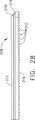
FIG. 28 is a side view of a tissue pad in the clamp type coagulation apparatus.
FIG. 29 is a front view of a tissue pad in the clamp type coagulation apparatus.
FIG. 30 is a perspective view of a tissue pad in the clamp type coagulation apparatus.
FIG. 31 is a lower perspective view of a clamp arm in the clamp type solidification apparatus.
32 is a first cross-sectional view of the clamp arm shown in FIG. 31. FIG.
33 is a second cross-sectional view of the clamp arm shown in FIG. 31. FIG.
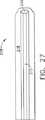
FIG. 34 is a bottom view of a blade in the clamp type solidification apparatus.
FIG. 35 is a cross-sectional view of a blade in the clamp type solidification apparatus.
FIG. 35A is a cross-sectional view of a blade in another embodiment of the clamp-type solidification device.
FIG. 36 is a perspective view of an end-effector in the clamp type coagulation apparatus.
[Explanation of symbols]
DESCRIPTION OF
Claims (16)
Translated fromJapaneseアクチュエータを有するハウジングと、
前記ハウジングに連結している基端部と先端部とを有する外側チューブを備えており、当該外側チューブが長手軸を定めており、さらに、
前記外側チューブの中に往復動可能に配置されている作動要素を備えており、当該作動要素が前記アクチュエータに操作可能に接続されており、さらに、
前記外側チューブの中に配置されている超音波導波管を備えており、当該超音波導波管が前記外側チューブの先端部から先端側に延在して非対称垂直面を定めている湾曲状のエンド−エフェクターを有しており、
前記エンド−エフェクターが広いエッジ部分および狭いエッジ部分を含み、広いエッジ部分が第1平行表面および第2平行表面により定められ、当該狭いエッジ部分が第1表面および第2表面の交線により定められていて、前記第1表面が凹面状であって前記第1平行表面と交差すると共に前記エンド−エフェクターの基端側に延在していて当該第1表面の長さを定め、前記第2表面が凸面状であって前記第2平行表面と交差しており、さらに、
前記外側チューブの先端部に旋回可能に取り付けられているクランプ・アームを備えており、このクランプ・アームが当該クランプ・アームと前記エンド−エフェクターの広いエッジ部分との間に組織をクランプするためにエンド−エフェクターに対して旋回移動を行い、当該旋回移動が水平軸の回りに生じて、前記クランプ・アームの旋回移動における円弧が前記垂直面内に定められており、当該垂直面が前記長手軸および前記水平軸の両方に対して直交している垂直軸を有しており、前記クランプ・アームが前記作動要素に操作可能に接続していて、当該作動要素の往復移動により前記クランプ・アームが前記垂直面に沿って旋回し、
前記第1表面の前記長さが前記エンド−エフェクターの偏位を前記垂直面内において最小にするように当該導波管を平衡化する超音波クランプ式凝固装置。In the ultrasonic clamp type coagulator,
A housing having an actuator;
Includes an outer tube havinga proximal portionand a distal portion that is connected to said housing, said outertube has established along hand shaft, further,
An actuating element that is reciprocally disposed in the outer tube, the actuating element being operably connected to the actuator; and
Includes an ultrasonic waveguide is positioned within said outer tube, curved in which the ultrasonic waveguide are setasymmetric vertical plane extending distally from the distal end of said outer tube End-effector
The end-effectorincludes a wide edge portion and a narrow edge portion, the wide edge portion is defined by afirst parallel surface and a second parallel surface, and the narrow edge portion is defined bya line of intersection of the firstsurface and the secondsurface. It has been, the said end with the firstsurface intersects the firstparallel surface a concave - they extendproximally effector defines a lengthof the firstsurface, the secondsurface Is convex and intersects the secondparallel surface ;
A clamp arm pivotally attached to the distal end of the outer tube, the clamp arm for clamping tissue between the clamp arm and the wide edge portion of the end-effector end - perform pivotal movement relative to the effector, the pivotal movementis caused around thehorizontal axis and the arc is defined within the verticalplane in the pivotal movement of the clamp arm, the verticalplane is the longitudinal has axial andvertical axesthat are orthogonal to both the horizontal axis and the clamp arm is not operatively connected to said actuating element, the clamping by the reciprocal movement of the actuating element arm pivots along said verticalplane,
The previousSulfur butterfly of the firstsurface end - effector excursions ultrasonic clamp coagulator apparatus for balancing the waveguide so as to minimize in said verticalplane.
基端部と、
先端部と、
第1平行表面および第2平行表面により定められた広いエッジ部分と、
狭いエッジ部分を備えており、当該狭いエッジ部分が第1表面および第2表面の交線により定められていて、前記第1表面が凹面状であって前記第1平行表面と交差すると共に前記先端部から前記基端部に向かって前記ブレードの基端側に延在していて、当該第1表面の長さを定め、前記第2表面が凸面状であって前記第2平行表面と交差しており、
前記ブレードが湾曲状であって非対称垂直面を定めている超音波外科器具用のブレード。In blades for ultrasonic surgical instruments,
A proximal end;
The tip,
A wide edge portion defined by the firstparallel surface and the secondparallel surface ;
A narrow edge portion that is defined by a line of intersection of the firstsurface and the secondsurface , wherein the firstsurface is concave and intersects the firstparallel surface and the tip Extending from the part towardthe base end side of the blade, definingthe length of the firstsurface , the secondsurface being convex and intersecting the secondparallel surface. And
A blade for an ultrasonic surgical instrument, wherein the blade is curved and defines anasymmetric vertical plane .
基端部と、
先端部と、
第1表面および第2表面の間に配置された広いエッジ部分と、
狭いエッジ部分を備えており、当該狭いエッジ部分が第1湾曲面および第2湾曲面の交線により定められていて、前記第1湾曲面が、前記交線から当該第1湾曲面が前記第1表面と交差する位置まで凹面状であると共に、前記先端部から前記基端部に向かって前記ブレードの基端側に延在していて、当該第1湾曲面の長さを定め、前記第2湾曲面が、前記交線から当該第2湾曲面が前記第2表面と交差する位置まで凸面状であり、
前記ブレードが湾曲状であって非対称垂直面を定めているブレード。In blades for ultrasonic surgical instruments,
A proximal end;
The tip,
A wide edge portion disposed between the firstsurface and the secondsurface ;
Has a narrow edge portion, the narrow edges are not defined by the line of intersection of the firstcurved surface and secondcurved surface, the firstcurved surface, the firstcurved surface from the line of intersection is the first A concave surface up to a position intersecting onesurface, and extending from the distal end towardthe proximal end of the blade towardthe proximal end of the blade, determining a length of the firstcurved surface , 2curved surfaces are convex from the intersecting line to a position where the secondcurved surface intersects the secondsurface ;
A blade that is curved and defines anasymmetric vertical plane .
(A)不所望なブレード偏位の最大の許容可能な量を選択するステップと、
(B)前記ブレードの長さに沿って当該ブレードの一部分から一定量の材料を除去することにより当該ブレードに機能的な非対称部分を加えるステップを含み、前記機能的な非対称部分の長さが前記ステップ(A)において確認された不所望な偏位の許容可能な量を満足し、
前記ブレードが湾曲状であって非対称垂直面を定めると共に、第1平行表面および第2平行表面により定められた広いエッジ部分と、狭いエッジ部分を備えており、
前記ステップ(B)において、前記機能的な非対称部分が前記狭いエッジ部分であり、当該狭いエッジ部分が第1表面および第2表面の交線により定められていて、前記第1表面が凹面状であって前記第1平行表面と交差し、前記第2表面が凸面状であって前記第2平行表面と交差しており、
前記第1表面が前記ブレードの先端部から基端部に向かって当該ブレードの基端側に延在していて、前記機能的な非対称部分の前記長さを定める方法。In a method of equilibrating an ultrasonic blade,
(A)selecting a maximum acceptable amount of undesired blade deflections,
(B) comprises thestep of adding a functional asymmetries to the blade by removing an amount of material from a portion of the bladeof the blade along the length, the lengthof the functional asymmetries said Satisfying an acceptable amount of undesired excursions identified instep (A),
The blade is curved and defines anasymmetric vertical surface , and includes a wide edge portion defined by the firstparallel surface and the secondparallel surface, and a narrow edge portion;
In thestep (B), the functional asymmetric portion is the narrow edge portion, the narrow edge portion is defined by a line of intersection of the firstsurface and the secondsurface , and the firstsurface is concave. And intersects the firstparallel surface , the secondsurface is convex and intersects the secondparallel surface ,
Wherein said firstsurface is not extendproximally of the blade toward the proximal end from the distal end portion of the blade definesthe length of the functional asymmetries.
Applications Claiming Priority (3)
| Application Number | Priority Date | Filing Date | Title |
|---|---|---|---|
| US09/412,257US6325811B1 (en) | 1999-10-05 | 1999-10-05 | Blades with functional balance asymmetries for use with ultrasonic surgical instruments |
| US09/412,257 | 1999-10-05 | ||
| PCT/US2000/024652WO2001024713A1 (en) | 1999-10-05 | 2000-09-08 | Blades with functional balance asymmetries for use with ultrasonic surgical instruments |
Related Child Applications (1)
| Application Number | Title | Priority Date | Filing Date |
|---|---|---|---|
| JP2007237090ADivisionJP4675947B2 (en) | 1999-10-05 | 2007-09-12 | Blade with functional balancing asymmetric portion for use with an ultrasonic surgical instrument |
Publications (3)
| Publication Number | Publication Date |
|---|---|
| JP2003510158A JP2003510158A (en) | 2003-03-18 |
| JP2003510158A5 JP2003510158A5 (en) | 2009-11-19 |
| JP4549597B2true JP4549597B2 (en) | 2010-09-22 |
Family
ID=23632283
Family Applications (2)
| Application Number | Title | Priority Date | Filing Date |
|---|---|---|---|
| JP2001527714AExpired - LifetimeJP4549597B2 (en) | 1999-10-05 | 2000-09-08 | Blade with functional balancing asymmetric portion for use with an ultrasonic surgical instrument |
| JP2007237090AExpired - LifetimeJP4675947B2 (en) | 1999-10-05 | 2007-09-12 | Blade with functional balancing asymmetric portion for use with an ultrasonic surgical instrument |
Family Applications After (1)
| Application Number | Title | Priority Date | Filing Date |
|---|---|---|---|
| JP2007237090AExpired - LifetimeJP4675947B2 (en) | 1999-10-05 | 2007-09-12 | Blade with functional balancing asymmetric portion for use with an ultrasonic surgical instrument |
Country Status (8)
| Country | Link |
|---|---|
| US (8) | US6325811B1 (en) |
| EP (4) | EP1223870B1 (en) |
| JP (2) | JP4549597B2 (en) |
| AU (1) | AU783032B2 (en) |
| CA (1) | CA2385942C (en) |
| DE (1) | DE60043350D1 (en) |
| ES (2) | ES2562665T3 (en) |
| WO (1) | WO2001024713A1 (en) |
Families Citing this family (1073)
| Publication number | Priority date | Publication date | Assignee | Title |
|---|---|---|---|---|
| US6454781B1 (en)* | 1999-05-26 | 2002-09-24 | Ethicon Endo-Surgery, Inc. | Feedback control in an ultrasonic surgical instrument for improved tissue effects |
| US6325811B1 (en) | 1999-10-05 | 2001-12-04 | Ethicon Endo-Surgery, Inc. | Blades with functional balance asymmetries for use with ultrasonic surgical instruments |
| JP4233742B2 (en)* | 1999-10-05 | 2009-03-04 | エシコン・エンド−サージェリィ・インコーポレイテッド | Connecting curved clamp arms and tissue pads used with ultrasonic surgical instruments |
| US8398666B2 (en)* | 2000-05-16 | 2013-03-19 | Teleflex Medical Incorporated | Penetrating tip for trocar assembly |
| US6752815B2 (en)* | 2001-01-31 | 2004-06-22 | Ethicon Endo-Surgery, Inc. | Method and waveguides for changing the direction of longitudinal vibrations |
| US20080214967A1 (en)* | 2004-02-17 | 2008-09-04 | Ernest Aranyi | Ultrasonic surgical instrument |
| US20040054364A1 (en)* | 2002-02-08 | 2004-03-18 | Ernest Aranyi | Ultrasonic surgical instrument |
| EP2000106B1 (en) | 2001-02-08 | 2010-06-09 | Tyco Healthcare Group Lp | Ultrasonic surgical instrument |
| US20040097911A1 (en)* | 2001-02-13 | 2004-05-20 | Olympus Optical Co., Ltd. | Ultrasonic operating apparartus and tool for changing tip thereof |
| US8348880B2 (en)* | 2001-04-04 | 2013-01-08 | Ethicon Endo-Surgery, Inc. | Ultrasonic surgical instrument incorporating fluid management |
| US20020165577A1 (en)* | 2001-05-04 | 2002-11-07 | Ethicon Endo-Surgery, Inc. | Easily detachable ultrasonic clamping device |
| US11229472B2 (en) | 2001-06-12 | 2022-01-25 | Cilag Gmbh International | Modular battery powered handheld surgical instrument with multiple magnetic position sensors |
| WO2003013374A1 (en)* | 2001-08-06 | 2003-02-20 | Penn State Research Foundation | Multifunctional tool and method for minimally invasive surgery |
| CA2463083C (en) | 2001-10-11 | 2010-03-30 | Tyco Healthcare Group Lp | Long ultrasonic cutting blade formed of laminated smaller blades |
| CA2466031C (en) | 2001-11-07 | 2012-04-10 | Ethicon Endo-Surgery, Inc. | An ultrasonic clamp coagulator apparatus having an improved clamping end-effector |
| US20030212332A1 (en)* | 2002-05-13 | 2003-11-13 | Paul Fenton | Disposable ultrasonic soft tissue cutting and coagulation systems |
| US20030212392A1 (en)* | 2002-05-13 | 2003-11-13 | Paul Fenton | Ultrasonic soft tissue cutting and coagulation systems having a curvilinear blade member and clamp |
| US20030212422A1 (en)* | 2002-05-13 | 2003-11-13 | Paul Fenton | Ultrasonic soft tissue cutting and coagulation systems with movable vibrating probe and fixed receiving clamp |
| US20030212331A1 (en)* | 2002-05-13 | 2003-11-13 | Paul Fenton | Ultrasonic soft tissue cutting and coagulation systems having multiple superposed vibrational modes |
| ATE528046T1 (en)* | 2002-06-04 | 2011-10-15 | Sound Surgical Technologies Llc | ULTRASONIC DEVICE FOR TISSUE COAGULATION |
| DE10320412A1 (en)* | 2003-05-07 | 2004-11-25 | Berchtold Holding Gmbh | Ultrasonic surgical scissor shank incorporates groove limited at both ends for insertion of a removable clamping block |
| US8012136B2 (en) | 2003-05-20 | 2011-09-06 | Optimyst Systems, Inc. | Ophthalmic fluid delivery device and method of operation |
| CA2526362C (en) | 2003-05-20 | 2012-10-09 | James F. Collins | Ophthalmic drug delivery system |
| US9060770B2 (en) | 2003-05-20 | 2015-06-23 | Ethicon Endo-Surgery, Inc. | Robotically-driven surgical instrument with E-beam driver |
| US20070084897A1 (en) | 2003-05-20 | 2007-04-19 | Shelton Frederick E Iv | Articulating surgical stapling instrument incorporating a two-piece e-beam firing mechanism |
| US8100824B2 (en) | 2003-05-23 | 2012-01-24 | Intuitive Surgical Operations, Inc. | Tool with articulation lock |
| US8182417B2 (en) | 2004-11-24 | 2012-05-22 | Intuitive Surgical Operations, Inc. | Articulating mechanism components and system for easy assembly and disassembly |
| US8562640B2 (en) | 2007-04-16 | 2013-10-22 | Intuitive Surgical Operations, Inc. | Tool with multi-state ratcheted end effector |
| US7090637B2 (en) | 2003-05-23 | 2006-08-15 | Novare Surgical Systems, Inc. | Articulating mechanism for remote manipulation of a surgical or diagnostic tool |
| US7410483B2 (en) | 2003-05-23 | 2008-08-12 | Novare Surgical Systems, Inc. | Hand-actuated device for remote manipulation of a grasping tool |
| CA2529740C (en) | 2003-06-17 | 2013-12-24 | Ethicon Endo-Surgery, Inc. | Hand activated ultrasonic instrument |
| EP1635717B1 (en)* | 2003-06-20 | 2010-02-17 | Interventional & Surgical Innovations, LLC | A device for grasping and/or severing |
| EP1680028B1 (en) | 2003-10-17 | 2012-01-25 | Tyco Healthcare Group LP | Surgical stapling device |
| US7163548B2 (en)* | 2003-11-05 | 2007-01-16 | Ethicon Endo-Surgery, Inc | Ultrasonic surgical blade and instrument having a gain step |
| JP4262631B2 (en)* | 2004-01-13 | 2009-05-13 | オリンパス株式会社 | Ultrasonic treatment device |
| US7297141B2 (en)* | 2004-01-20 | 2007-11-20 | Ethicon Endo-Surgery, Inc. | Method for accessing an operative space |
| US7585290B2 (en)* | 2004-01-20 | 2009-09-08 | Ethicon Endo-Surgery, Inc. | Medical device for providing access |
| US8182501B2 (en)* | 2004-02-27 | 2012-05-22 | Ethicon Endo-Surgery, Inc. | Ultrasonic surgical shears and method for sealing a blood vessel using same |
| US20050192611A1 (en)* | 2004-02-27 | 2005-09-01 | Houser Kevin L. | Ultrasonic surgical instrument, shears and tissue pad, method for sealing a blood vessel and method for transecting patient tissue |
| CA2557649C (en)* | 2004-02-27 | 2011-10-04 | Ethicon Endo-Surgery Inc. | Ultrasonic surgical shears and tissue pad for same |
| US20050192610A1 (en)* | 2004-02-27 | 2005-09-01 | Houser Kevin L. | Ultrasonic surgical shears and tissue pad for same |
| US20050234484A1 (en)* | 2004-02-27 | 2005-10-20 | Houser Kevin L | Ultrasonic surgical blade having transverse and longitudinal vibration |
| JP4249064B2 (en)* | 2004-03-10 | 2009-04-02 | オリンパス株式会社 | Endoscope |
| CN1951000B (en) | 2004-05-21 | 2011-08-31 | 守屋正 | Ultrasonic motor |
| US7828808B2 (en) | 2004-06-07 | 2010-11-09 | Novare Surgical Systems, Inc. | Link systems and articulation mechanisms for remote manipulation of surgical or diagnostic tools |
| US7678117B2 (en) | 2004-06-07 | 2010-03-16 | Novare Surgical Systems, Inc. | Articulating mechanism with flex-hinged links |
| EP1755461B1 (en) | 2004-06-16 | 2014-01-01 | Smith & Nephew, Inc. | Suture passing device |
| US11890012B2 (en) | 2004-07-28 | 2024-02-06 | Cilag Gmbh International | Staple cartridge comprising cartridge body and attached support |
| US8215531B2 (en) | 2004-07-28 | 2012-07-10 | Ethicon Endo-Surgery, Inc. | Surgical stapling instrument having a medical substance dispenser |
| US9072535B2 (en) | 2011-05-27 | 2015-07-07 | Ethicon Endo-Surgery, Inc. | Surgical stapling instruments with rotatable staple deployment arrangements |
| US11998198B2 (en) | 2004-07-28 | 2024-06-04 | Cilag Gmbh International | Surgical stapling instrument incorporating a two-piece E-beam firing mechanism |
| JP4300169B2 (en)* | 2004-09-10 | 2009-07-22 | アロカ株式会社 | Ultrasound surgical device |
| US20060079879A1 (en)* | 2004-10-08 | 2006-04-13 | Faller Craig N | Actuation mechanism for use with an ultrasonic surgical instrument |
| US7479148B2 (en)* | 2004-11-08 | 2009-01-20 | Crescendo Technologies, Llc | Ultrasonic shear with asymmetrical motion |
| US9700334B2 (en) | 2004-11-23 | 2017-07-11 | Intuitive Surgical Operations, Inc. | Articulating mechanisms and link systems with torque transmission in remote manipulation of instruments and tools |
| US7785252B2 (en) | 2004-11-23 | 2010-08-31 | Novare Surgical Systems, Inc. | Articulating sheath for flexible instruments |
| US8628534B2 (en)* | 2005-02-02 | 2014-01-14 | DePuy Synthes Products, LLC | Ultrasonic cutting device |
| US7473223B2 (en)* | 2005-02-07 | 2009-01-06 | Peter Edward Fetzer | Push-button activated grasper for surgical retractor |
| GB2423931B (en)* | 2005-03-03 | 2009-08-26 | Michael John Radley Young | Ultrasonic cutting tool |
| US20060211943A1 (en)* | 2005-03-15 | 2006-09-21 | Crescendo Technologies, Llc | Ultrasonic blade with terminal end balance features |
| US20070016236A1 (en)* | 2005-07-18 | 2007-01-18 | Crescendo Technologies, Llc | Balanced ultrasonic curved blade |
| US10159482B2 (en) | 2005-08-31 | 2018-12-25 | Ethicon Llc | Fastener cartridge assembly comprising a fixed anvil and different staple heights |
| US11246590B2 (en) | 2005-08-31 | 2022-02-15 | Cilag Gmbh International | Staple cartridge including staple drivers having different unfired heights |
| US7934630B2 (en) | 2005-08-31 | 2011-05-03 | Ethicon Endo-Surgery, Inc. | Staple cartridges for forming staples having differing formed staple heights |
| US9237891B2 (en) | 2005-08-31 | 2016-01-19 | Ethicon Endo-Surgery, Inc. | Robotically-controlled surgical stapling devices that produce formed staples having different lengths |
| US11484312B2 (en) | 2005-08-31 | 2022-11-01 | Cilag Gmbh International | Staple cartridge comprising a staple driver arrangement |
| US7669746B2 (en) | 2005-08-31 | 2010-03-02 | Ethicon Endo-Surgery, Inc. | Staple cartridges for forming staples having differing formed staple heights |
| US8152825B2 (en)* | 2005-10-14 | 2012-04-10 | Ethicon Endo-Surgery, Inc. | Medical ultrasound system and handpiece and methods for making and tuning |
| US20070191713A1 (en)* | 2005-10-14 | 2007-08-16 | Eichmann Stephen E | Ultrasonic device for cutting and coagulating |
| AU2016238977B2 (en)* | 2005-10-14 | 2019-03-14 | Ethicon Endo-Surgery, Inc. | Ultrasonic device for cutting and coagulating |
| US20070106317A1 (en) | 2005-11-09 | 2007-05-10 | Shelton Frederick E Iv | Hydraulically and electrically actuated articulation joints for surgical instruments |
| US8246642B2 (en)* | 2005-12-01 | 2012-08-21 | Ethicon Endo-Surgery, Inc. | Ultrasonic medical instrument and medical instrument connection assembly |
| US20070138723A1 (en)* | 2005-12-19 | 2007-06-21 | Hsu Chin L | Clamping device having replaceable clamping members |
| US20070149881A1 (en)* | 2005-12-22 | 2007-06-28 | Rabin Barry H | Ultrasonically Powered Medical Devices and Systems, and Methods and Uses Thereof |
| US20070167965A1 (en)* | 2006-01-05 | 2007-07-19 | Ethicon Endo-Surgery, Inc. | Ultrasonic medical instrument |
| US7621930B2 (en)* | 2006-01-20 | 2009-11-24 | Ethicon Endo-Surgery, Inc. | Ultrasound medical instrument having a medical ultrasonic blade |
| US20070173872A1 (en)* | 2006-01-23 | 2007-07-26 | Ethicon Endo-Surgery, Inc. | Surgical instrument for cutting and coagulating patient tissue |
| US8186555B2 (en) | 2006-01-31 | 2012-05-29 | Ethicon Endo-Surgery, Inc. | Motor-driven surgical cutting and fastening instrument with mechanical closure system |
| US8820603B2 (en) | 2006-01-31 | 2014-09-02 | Ethicon Endo-Surgery, Inc. | Accessing data stored in a memory of a surgical instrument |
| US11224427B2 (en) | 2006-01-31 | 2022-01-18 | Cilag Gmbh International | Surgical stapling system including a console and retraction assembly |
| US20120292367A1 (en) | 2006-01-31 | 2012-11-22 | Ethicon Endo-Surgery, Inc. | Robotically-controlled end effector |
| US8708213B2 (en) | 2006-01-31 | 2014-04-29 | Ethicon Endo-Surgery, Inc. | Surgical instrument having a feedback system |
| US20110024477A1 (en) | 2009-02-06 | 2011-02-03 | Hall Steven G | Driven Surgical Stapler Improvements |
| US7845537B2 (en) | 2006-01-31 | 2010-12-07 | Ethicon Endo-Surgery, Inc. | Surgical instrument having recording capabilities |
| US7753904B2 (en) | 2006-01-31 | 2010-07-13 | Ethicon Endo-Surgery, Inc. | Endoscopic surgical instrument with a handle that can articulate with respect to the shaft |
| US20110295295A1 (en) | 2006-01-31 | 2011-12-01 | Ethicon Endo-Surgery, Inc. | Robotically-controlled surgical instrument having recording capabilities |
| US11278279B2 (en) | 2006-01-31 | 2022-03-22 | Cilag Gmbh International | Surgical instrument assembly |
| US11793518B2 (en) | 2006-01-31 | 2023-10-24 | Cilag Gmbh International | Powered surgical instruments with firing system lockout arrangements |
| US20070191686A1 (en)* | 2006-02-13 | 2007-08-16 | Levahn Intellectual Property Holding Company, Llc | Method of making a surgical clamp |
| US7467128B2 (en)* | 2006-02-15 | 2008-12-16 | Microsoft Corporation | Maintenance of materialized outer-join views |
| US20070191712A1 (en)* | 2006-02-15 | 2007-08-16 | Ethicon Endo-Surgery, Inc. | Method for sealing a blood vessel, a medical system and a medical instrument |
| US7854735B2 (en)* | 2006-02-16 | 2010-12-21 | Ethicon Endo-Surgery, Inc. | Energy-based medical treatment system and method |
| US8992422B2 (en) | 2006-03-23 | 2015-03-31 | Ethicon Endo-Surgery, Inc. | Robotically-controlled endoscopic accessory channel |
| US9675375B2 (en) | 2006-03-29 | 2017-06-13 | Ethicon Llc | Ultrasonic surgical system and method |
| JP2007275291A (en)* | 2006-04-06 | 2007-10-25 | Olympus Medical Systems Corp | Ultrasonic treatment device |
| US8366727B2 (en) | 2006-06-01 | 2013-02-05 | Ethicon Endo-Surgery, Inc. | Tissue pad ultrasonic surgical instrument |
| US9561045B2 (en) | 2006-06-13 | 2017-02-07 | Intuitive Surgical Operations, Inc. | Tool with rotation lock |
| US8409244B2 (en)* | 2007-04-16 | 2013-04-02 | Intuitive Surgical Operations, Inc. | Tool with end effector force limiter |
| US7862554B2 (en)* | 2007-04-16 | 2011-01-04 | Intuitive Surgical Operations, Inc. | Articulating tool with improved tension member system |
| US8322455B2 (en) | 2006-06-27 | 2012-12-04 | Ethicon Endo-Surgery, Inc. | Manually driven surgical cutting and fastening instrument |
| US8403196B2 (en) | 2006-09-08 | 2013-03-26 | Covidien Lp | Dissection tip and introducer for surgical instrument |
| US8136711B2 (en) | 2006-09-08 | 2012-03-20 | Tyco Healthcare Group Lp | Dissection tip and introducer for surgical instrument |
| US10568652B2 (en) | 2006-09-29 | 2020-02-25 | Ethicon Llc | Surgical staples having attached drivers of different heights and stapling instruments for deploying the same |
| US11980366B2 (en) | 2006-10-03 | 2024-05-14 | Cilag Gmbh International | Surgical instrument |
| US20080147092A1 (en)* | 2006-10-23 | 2008-06-19 | Michael Rogge | Hybrid energy instrument combined with clip application capability |
| DE202006020278U1 (en)* | 2006-12-18 | 2008-04-30 | Söring GmbH | Surgical instrument |
| US8652120B2 (en) | 2007-01-10 | 2014-02-18 | Ethicon Endo-Surgery, Inc. | Surgical instrument with wireless communication between control unit and sensor transponders |
| US8632535B2 (en) | 2007-01-10 | 2014-01-21 | Ethicon Endo-Surgery, Inc. | Interlock and surgical instrument including same |
| US11291441B2 (en) | 2007-01-10 | 2022-04-05 | Cilag Gmbh International | Surgical instrument with wireless communication between control unit and remote sensor |
| US8684253B2 (en) | 2007-01-10 | 2014-04-01 | Ethicon Endo-Surgery, Inc. | Surgical instrument with wireless communication between a control unit of a robotic system and remote sensor |
| US11039836B2 (en) | 2007-01-11 | 2021-06-22 | Cilag Gmbh International | Staple cartridge for use with a surgical stapling instrument |
| US20080169333A1 (en) | 2007-01-11 | 2008-07-17 | Shelton Frederick E | Surgical stapler end effector with tapered distal end |
| JP5165696B2 (en)* | 2007-01-16 | 2013-03-21 | エシコン・エンド−サージェリィ・インコーポレイテッド | Ultrasonic device for cutting and coagulation |
| US7673782B2 (en) | 2007-03-15 | 2010-03-09 | Ethicon Endo-Surgery, Inc. | Surgical stapling instrument having a releasable buttress material |
| US8911460B2 (en) | 2007-03-22 | 2014-12-16 | Ethicon Endo-Surgery, Inc. | Ultrasonic surgical instruments |
| US8142461B2 (en) | 2007-03-22 | 2012-03-27 | Ethicon Endo-Surgery, Inc. | Surgical instruments |
| CN101674780B (en)* | 2007-03-22 | 2012-05-23 | 伊西康内外科公司 | Ultrasonic surgical instrument blades |
| US8226675B2 (en) | 2007-03-22 | 2012-07-24 | Ethicon Endo-Surgery, Inc. | Surgical instruments |
| US20080234709A1 (en) | 2007-03-22 | 2008-09-25 | Houser Kevin L | Ultrasonic surgical instrument and cartilage and bone shaping blades therefor |
| US8057498B2 (en) | 2007-11-30 | 2011-11-15 | Ethicon Endo-Surgery, Inc. | Ultrasonic surgical instrument blades |
| US8790285B2 (en)* | 2007-05-18 | 2014-07-29 | Weil Institute of Critical Care Medicine | Enhanced chest compressor |
| USD767353S1 (en) | 2007-05-22 | 2016-09-27 | Ethicon Endo-Surgery, Llc | Torque wrench for ultrasonic instrument |
| US20080294051A1 (en)* | 2007-05-25 | 2008-11-27 | Machiko Koshigoe | Ultrasonic operating apparatus |
| US9271751B2 (en) | 2007-05-29 | 2016-03-01 | Ethicon Endo-Surgery, Llc | Ultrasonic surgical system |
| US8931682B2 (en) | 2007-06-04 | 2015-01-13 | Ethicon Endo-Surgery, Inc. | Robotically-controlled shaft based rotary drive systems for surgical instruments |
| US11564682B2 (en) | 2007-06-04 | 2023-01-31 | Cilag Gmbh International | Surgical stapler device |
| US20090069830A1 (en)* | 2007-06-07 | 2009-03-12 | Piezo Resonance Innovations, Inc. | Eye surgical tool |
| US7753245B2 (en) | 2007-06-22 | 2010-07-13 | Ethicon Endo-Surgery, Inc. | Surgical stapling instruments |
| US11849941B2 (en) | 2007-06-29 | 2023-12-26 | Cilag Gmbh International | Staple cartridge having staple cavities extending at a transverse angle relative to a longitudinal cartridge axis |
| US8882791B2 (en) | 2007-07-27 | 2014-11-11 | Ethicon Endo-Surgery, Inc. | Ultrasonic surgical instruments |
| US8348967B2 (en) | 2007-07-27 | 2013-01-08 | Ethicon Endo-Surgery, Inc. | Ultrasonic surgical instruments |
| US8523889B2 (en) | 2007-07-27 | 2013-09-03 | Ethicon Endo-Surgery, Inc. | Ultrasonic end effectors with increased active length |
| JP5474783B2 (en)* | 2007-07-27 | 2014-04-16 | エシコン・エンド−サージェリィ・インコーポレイテッド | Ultrasonic surgical instrument |
| US8257377B2 (en) | 2007-07-27 | 2012-09-04 | Ethicon Endo-Surgery, Inc. | Multiple end effectors ultrasonic surgical instruments |
| US8808319B2 (en) | 2007-07-27 | 2014-08-19 | Ethicon Endo-Surgery, Inc. | Surgical instruments |
| US8430898B2 (en) | 2007-07-31 | 2013-04-30 | Ethicon Endo-Surgery, Inc. | Ultrasonic surgical instruments |
| US8252012B2 (en) | 2007-07-31 | 2012-08-28 | Ethicon Endo-Surgery, Inc. | Ultrasonic surgical instrument with modulator |
| US8512365B2 (en) | 2007-07-31 | 2013-08-20 | Ethicon Endo-Surgery, Inc. | Surgical instruments |
| US9044261B2 (en) | 2007-07-31 | 2015-06-02 | Ethicon Endo-Surgery, Inc. | Temperature controlled ultrasonic surgical instruments |
| USD594983S1 (en) | 2007-10-05 | 2009-06-23 | Ethicon Endo-Surgery, Inc. | Handle assembly for surgical instrument |
| EP2217157A2 (en) | 2007-10-05 | 2010-08-18 | Ethicon Endo-Surgery, Inc. | Ergonomic surgical instruments |
| CA2702075C (en)* | 2007-10-10 | 2016-06-28 | Ethicon Endo-Surgery, Inc. | Ultrasonic device for cutting and coagulating |
| US10010339B2 (en) | 2007-11-30 | 2018-07-03 | Ethicon Llc | Ultrasonic surgical blades |
| US7901423B2 (en) | 2007-11-30 | 2011-03-08 | Ethicon Endo-Surgery, Inc. | Folded ultrasonic end effectors with increased active length |
| US8663262B2 (en) | 2007-12-03 | 2014-03-04 | Covidien Ag | Battery assembly for battery-powered surgical instruments |
| US9314261B2 (en) | 2007-12-03 | 2016-04-19 | Covidien Ag | Battery-powered hand-held ultrasonic surgical cautery cutting device |
| US8334468B2 (en) | 2008-11-06 | 2012-12-18 | Covidien Ag | Method of switching a cordless hand-held ultrasonic cautery cutting device |
| US20090143800A1 (en) | 2007-12-03 | 2009-06-04 | Derek Dee Deville | Cordless Hand-Held Ultrasonic Cautery Cutting Device |
| US9107690B2 (en) | 2007-12-03 | 2015-08-18 | Covidien Ag | Battery-powered hand-held ultrasonic surgical cautery cutting device |
| US8061014B2 (en) | 2007-12-03 | 2011-11-22 | Covidien Ag | Method of assembling a cordless hand-held ultrasonic cautery cutting device |
| US8425545B2 (en) | 2007-12-03 | 2013-04-23 | Covidien Ag | Cordless hand-held ultrasonic cautery cutting device and method |
| US9017355B2 (en) | 2007-12-03 | 2015-04-28 | Covidien Ag | Battery-powered hand-held ultrasonic surgical cautery cutting device |
| US7869307B2 (en) | 2008-01-25 | 2011-01-11 | Olympus Medical Systems Corp. | Ultrasonic transmission member |
| US8573465B2 (en) | 2008-02-14 | 2013-11-05 | Ethicon Endo-Surgery, Inc. | Robotically-controlled surgical end effector system with rotary actuated closure systems |
| JP5410110B2 (en) | 2008-02-14 | 2014-02-05 | エシコン・エンド−サージェリィ・インコーポレイテッド | Surgical cutting / fixing instrument with RF electrode |
| US8758391B2 (en) | 2008-02-14 | 2014-06-24 | Ethicon Endo-Surgery, Inc. | Interchangeable tools for surgical instruments |
| US8636736B2 (en) | 2008-02-14 | 2014-01-28 | Ethicon Endo-Surgery, Inc. | Motorized surgical cutting and fastening instrument |
| US9179912B2 (en) | 2008-02-14 | 2015-11-10 | Ethicon Endo-Surgery, Inc. | Robotically-controlled motorized surgical cutting and fastening instrument |
| US7819298B2 (en) | 2008-02-14 | 2010-10-26 | Ethicon Endo-Surgery, Inc. | Surgical stapling apparatus with control features operable with one hand |
| US11986183B2 (en) | 2008-02-14 | 2024-05-21 | Cilag Gmbh International | Surgical cutting and fastening instrument comprising a plurality of sensors to measure an electrical parameter |
| US7866527B2 (en) | 2008-02-14 | 2011-01-11 | Ethicon Endo-Surgery, Inc. | Surgical stapling apparatus with interlockable firing system |
| US9585657B2 (en) | 2008-02-15 | 2017-03-07 | Ethicon Endo-Surgery, Llc | Actuator for releasing a layer of material from a surgical end effector |
| US8398673B2 (en)* | 2008-02-15 | 2013-03-19 | Surgical Innovations V.O.F. | Surgical instrument for grasping and cutting tissue |
| ES2442241T3 (en) | 2008-03-31 | 2014-02-10 | Applied Medical Resources Corporation | Electrosurgical system with a switching mechanism |
| US8226665B2 (en)* | 2008-04-04 | 2012-07-24 | Tyco Healthcare Group Lp | Ultrasonic needle driver |
| WO2009132072A2 (en)* | 2008-04-22 | 2009-10-29 | Ethicon Endo-Surgery, Inc. | Methods and devices for dissecting tissue |
| JP2011518026A (en)* | 2008-04-22 | 2011-06-23 | エシコン・エンド−サージェリィ・インコーポレイテッド | Method and apparatus for providing direction to a surgical tool |
| US9247953B2 (en) | 2008-08-01 | 2016-02-02 | Syntheon, Llc | Medical ultrasonic cauterization and cutting device and method |
| US9089360B2 (en) | 2008-08-06 | 2015-07-28 | Ethicon Endo-Surgery, Inc. | Devices and techniques for cutting and coagulating tissue |
| US8058771B2 (en) | 2008-08-06 | 2011-11-15 | Ethicon Endo-Surgery, Inc. | Ultrasonic device for cutting and coagulating with stepped output |
| US8465475B2 (en) | 2008-08-18 | 2013-06-18 | Intuitive Surgical Operations, Inc. | Instrument with multiple articulation locks |
| US20100063527A1 (en)* | 2008-09-05 | 2010-03-11 | Beaupre Jean Michael | Tissue pad |
| WO2010030850A2 (en)* | 2008-09-12 | 2010-03-18 | Ethicon Endo-Surgery, Inc. | Ultrasonic device for fingertip control |
| US9107688B2 (en) | 2008-09-12 | 2015-08-18 | Ethicon Endo-Surgery, Inc. | Activation feature for surgical instrument with pencil grip |
| US9386983B2 (en) | 2008-09-23 | 2016-07-12 | Ethicon Endo-Surgery, Llc | Robotically-controlled motorized surgical instrument |
| US8210411B2 (en) | 2008-09-23 | 2012-07-03 | Ethicon Endo-Surgery, Inc. | Motor-driven surgical cutting instrument |
| US9005230B2 (en) | 2008-09-23 | 2015-04-14 | Ethicon Endo-Surgery, Inc. | Motorized surgical instrument |
| US11648005B2 (en) | 2008-09-23 | 2023-05-16 | Cilag Gmbh International | Robotically-controlled motorized surgical instrument with an end effector |
| US20100331873A1 (en) | 2009-06-30 | 2010-12-30 | Dannaher William D | Ultrasonic device for cutting and coagulating |
| US8608045B2 (en) | 2008-10-10 | 2013-12-17 | Ethicon Endo-Sugery, Inc. | Powered surgical cutting and stapling apparatus with manually retractable firing system |
| CN101744653B (en)* | 2008-12-04 | 2012-06-13 | 林运男 | Surgical shearing device for endoscopic surgery |
| US8517239B2 (en) | 2009-02-05 | 2013-08-27 | Ethicon Endo-Surgery, Inc. | Surgical stapling instrument comprising a magnetic element driver |
| RU2525225C2 (en) | 2009-02-06 | 2014-08-10 | Этикон Эндо-Серджери, Инк. | Improvement of drive surgical suturing instrument |
| US9700339B2 (en) | 2009-05-20 | 2017-07-11 | Ethicon Endo-Surgery, Inc. | Coupling arrangements and methods for attaching tools to ultrasonic surgical instruments |
| US20100298743A1 (en)* | 2009-05-20 | 2010-11-25 | Ethicon Endo-Surgery, Inc. | Thermally-activated coupling arrangements and methods for attaching tools to ultrasonic surgical instruments |
| US8650728B2 (en) | 2009-06-24 | 2014-02-18 | Ethicon Endo-Surgery, Inc. | Method of assembling a transducer for a surgical instrument |
| US8623040B2 (en) | 2009-07-01 | 2014-01-07 | Alcon Research, Ltd. | Phacoemulsification hook tip |
| CN102497827B (en) | 2009-07-15 | 2016-06-01 | 伊西康内外科公司 | Electrosurgical generator for ultrasonic surgical instrument |
| US8663220B2 (en) | 2009-07-15 | 2014-03-04 | Ethicon Endo-Surgery, Inc. | Ultrasonic surgical instruments |
| US9017326B2 (en) | 2009-07-15 | 2015-04-28 | Ethicon Endo-Surgery, Inc. | Impedance monitoring apparatus, system, and method for ultrasonic surgical instruments |
| US8461744B2 (en) | 2009-07-15 | 2013-06-11 | Ethicon Endo-Surgery, Inc. | Rotating transducer mount for ultrasonic surgical instruments |
| US20110022078A1 (en) | 2009-07-23 | 2011-01-27 | Cameron Dale Hinman | Articulating mechanism |
| US20110196418A1 (en)* | 2009-07-28 | 2011-08-11 | Salvatore Castro | Flexible medical instruments |
| CA2770743C (en) | 2009-08-14 | 2018-05-01 | Ethicon Endo-Surgery, Inc. | Ultrasonic surgical apparatus and silicon waveguide and methods for use thereof |
| US9737735B2 (en) | 2009-08-14 | 2017-08-22 | Ethicon Llc | Ultrasonic surgical apparatus with silicon waveguide |
| US9649120B1 (en) | 2009-08-18 | 2017-05-16 | University Of South Florida | Minimally invasive surgery platform attachment apparatus |
| US8207651B2 (en) | 2009-09-16 | 2012-06-26 | Tyco Healthcare Group Lp | Low energy or minimum disturbance method for measuring frequency response functions of ultrasonic surgical devices in determining optimum operating point |
| US8112871B2 (en) | 2009-09-28 | 2012-02-14 | Tyco Healthcare Group Lp | Method for manufacturing electrosurgical seal plates |
| US10441345B2 (en) | 2009-10-09 | 2019-10-15 | Ethicon Llc | Surgical generator for ultrasonic and electrosurgical devices |
| US9168054B2 (en) | 2009-10-09 | 2015-10-27 | Ethicon Endo-Surgery, Inc. | Surgical generator for ultrasonic and electrosurgical devices |
| US9295485B2 (en) | 2009-10-09 | 2016-03-29 | Ethicon Endo-Surgery, Inc. | Loader for exchanging end effectors in vivo |
| US9050093B2 (en) | 2009-10-09 | 2015-06-09 | Ethicon Endo-Surgery, Inc. | Surgical generator for ultrasonic and electrosurgical devices |
| US11090104B2 (en) | 2009-10-09 | 2021-08-17 | Cilag Gmbh International | Surgical generator for ultrasonic and electrosurgical devices |
| US10172669B2 (en) | 2009-10-09 | 2019-01-08 | Ethicon Llc | Surgical instrument comprising an energy trigger lockout |
| EP2485662B1 (en) | 2009-10-09 | 2015-09-09 | Applied Medical Resources Corporation | Single port instruments |
| USRE47996E1 (en) | 2009-10-09 | 2020-05-19 | Ethicon Llc | Surgical generator for ultrasonic and electrosurgical devices |
| US20120259325A1 (en)* | 2009-10-09 | 2012-10-11 | Houser Kevin L | Laparoscopic Instrument with Attachable Energy End Effector |
| DE202009014310U1 (en) | 2009-10-22 | 2010-03-04 | Thomas Tontarra Grundstücksverwaltungs GmbH & Co. KG | Surgical instrument |
| USD700328S1 (en)* | 2009-11-20 | 2014-02-25 | Thomas Tontarra | Surgical rongeur |
| US8851354B2 (en) | 2009-12-24 | 2014-10-07 | Ethicon Endo-Surgery, Inc. | Surgical cutting instrument that analyzes tissue thickness |
| US8220688B2 (en) | 2009-12-24 | 2012-07-17 | Ethicon Endo-Surgery, Inc. | Motor-driven surgical cutting instrument with electric actuator directional control assembly |
| US8858553B2 (en)* | 2010-01-29 | 2014-10-14 | Covidien Lp | Dielectric jaw insert for electrosurgical end effector |
| US8382782B2 (en) | 2010-02-11 | 2013-02-26 | Ethicon Endo-Surgery, Inc. | Ultrasonic surgical instruments with partially rotating blade and fixed pad arrangement |
| US8323302B2 (en) | 2010-02-11 | 2012-12-04 | Ethicon Endo-Surgery, Inc. | Methods of using ultrasonically powered surgical instruments with rotatable cutting implements |
| US8531064B2 (en) | 2010-02-11 | 2013-09-10 | Ethicon Endo-Surgery, Inc. | Ultrasonically powered surgical instruments with rotating cutting implement |
| US8419759B2 (en) | 2010-02-11 | 2013-04-16 | Ethicon Endo-Surgery, Inc. | Ultrasonic surgical instrument with comb-like tissue trimming device |
| US8486096B2 (en) | 2010-02-11 | 2013-07-16 | Ethicon Endo-Surgery, Inc. | Dual purpose surgical instrument for cutting and coagulating tissue |
| US8579928B2 (en) | 2010-02-11 | 2013-11-12 | Ethicon Endo-Surgery, Inc. | Outer sheath and blade arrangements for ultrasonic surgical instruments |
| US8469981B2 (en) | 2010-02-11 | 2013-06-25 | Ethicon Endo-Surgery, Inc. | Rotatable cutting implement arrangements for ultrasonic surgical instruments |
| US8951272B2 (en) | 2010-02-11 | 2015-02-10 | Ethicon Endo-Surgery, Inc. | Seal arrangements for ultrasonically powered surgical instruments |
| US8961547B2 (en) | 2010-02-11 | 2015-02-24 | Ethicon Endo-Surgery, Inc. | Ultrasonic surgical instruments with moving cutting implement |
| US9259234B2 (en) | 2010-02-11 | 2016-02-16 | Ethicon Endo-Surgery, Llc | Ultrasonic surgical instruments with rotatable blade and hollow sheath arrangements |
| USD648434S1 (en)* | 2010-05-07 | 2011-11-08 | Karl Storz Gmbh & Co. Kg | Forceps inserts for laparoscopic Procedures |
| GB2480498A (en) | 2010-05-21 | 2011-11-23 | Ethicon Endo Surgery Inc | Medical device comprising RF circuitry |
| US10154923B2 (en) | 2010-07-15 | 2018-12-18 | Eyenovia, Inc. | Drop generating device |
| EA201390121A8 (en) | 2010-07-15 | 2014-02-28 | Коринтиан Офтэлмик, Инк. | METHOD AND SYSTEM FOR PERFORMING REMOTE TREATMENT AND CONTROL |
| WO2012009706A1 (en) | 2010-07-15 | 2012-01-19 | Corinthian Ophthalmic, Inc. | Drop generating device |
| EA201390120A3 (en) | 2010-07-15 | 2013-09-30 | Коринтиан Офтэлмик, Инк. | DELIVERY OF OPHTHALMIC MEDICINES |
| US8795327B2 (en) | 2010-07-22 | 2014-08-05 | Ethicon Endo-Surgery, Inc. | Electrosurgical instrument with separate closure and cutting members |
| US9192431B2 (en) | 2010-07-23 | 2015-11-24 | Ethicon Endo-Surgery, Inc. | Electrosurgical cutting and sealing instrument |
| US8783543B2 (en) | 2010-07-30 | 2014-07-22 | Ethicon Endo-Surgery, Inc. | Tissue acquisition arrangements and methods for surgical stapling devices |
| US10258505B2 (en) | 2010-09-17 | 2019-04-16 | Alcon Research, Ltd. | Balanced phacoemulsification tip |
| US9629814B2 (en) | 2010-09-30 | 2017-04-25 | Ethicon Endo-Surgery, Llc | Tissue thickness compensator configured to redistribute compressive forces |
| US9386988B2 (en) | 2010-09-30 | 2016-07-12 | Ethicon End-Surgery, LLC | Retainer assembly including a tissue thickness compensator |
| US10945731B2 (en) | 2010-09-30 | 2021-03-16 | Ethicon Llc | Tissue thickness compensator comprising controlled release and expansion |
| US12213666B2 (en) | 2010-09-30 | 2025-02-04 | Cilag Gmbh International | Tissue thickness compensator comprising layers |
| US11812965B2 (en) | 2010-09-30 | 2023-11-14 | Cilag Gmbh International | Layer of material for a surgical end effector |
| US9788834B2 (en) | 2010-09-30 | 2017-10-17 | Ethicon Llc | Layer comprising deployable attachment members |
| US11925354B2 (en) | 2010-09-30 | 2024-03-12 | Cilag Gmbh International | Staple cartridge comprising staples positioned within a compressible portion thereof |
| US9016542B2 (en) | 2010-09-30 | 2015-04-28 | Ethicon Endo-Surgery, Inc. | Staple cartridge comprising compressible distortion resistant components |
| US9351730B2 (en) | 2011-04-29 | 2016-05-31 | Ethicon Endo-Surgery, Llc | Tissue thickness compensator comprising channels |
| US11298125B2 (en) | 2010-09-30 | 2022-04-12 | Cilag Gmbh International | Tissue stapler having a thickness compensator |
| AU2011308509B8 (en) | 2010-10-01 | 2015-04-02 | Applied Medical Resources Corporation | Electrosurgical instrument |
| US8888809B2 (en) | 2010-10-01 | 2014-11-18 | Ethicon Endo-Surgery, Inc. | Surgical instrument with jaw member |
| US8979890B2 (en) | 2010-10-01 | 2015-03-17 | Ethicon Endo-Surgery, Inc. | Surgical instrument with jaw member |
| US8695866B2 (en) | 2010-10-01 | 2014-04-15 | Ethicon Endo-Surgery, Inc. | Surgical instrument having a power control circuit |
| US9308013B2 (en) | 2010-11-03 | 2016-04-12 | Gyrus Ent, L.L.C. | Surgical tool with sheath |
| US10959769B2 (en) | 2010-11-05 | 2021-03-30 | Ethicon Llc | Surgical instrument with slip ring assembly to power ultrasonic transducer |
| US9247986B2 (en) | 2010-11-05 | 2016-02-02 | Ethicon Endo-Surgery, Llc | Surgical instrument with ultrasonic transducer having integral switches |
| US10085792B2 (en) | 2010-11-05 | 2018-10-02 | Ethicon Llc | Surgical instrument with motorized attachment feature |
| US9526921B2 (en) | 2010-11-05 | 2016-12-27 | Ethicon Endo-Surgery, Llc | User feedback through end effector of surgical instrument |
| US9072523B2 (en) | 2010-11-05 | 2015-07-07 | Ethicon Endo-Surgery, Inc. | Medical device with feature for sterile acceptance of non-sterile reusable component |
| US9597143B2 (en) | 2010-11-05 | 2017-03-21 | Ethicon Endo-Surgery, Llc | Sterile medical instrument charging device |
| US20120116265A1 (en) | 2010-11-05 | 2012-05-10 | Houser Kevin L | Surgical instrument with charging devices |
| US9011471B2 (en) | 2010-11-05 | 2015-04-21 | Ethicon Endo-Surgery, Inc. | Surgical instrument with pivoting coupling to modular shaft and end effector |
| JP6054298B2 (en) | 2010-11-05 | 2016-12-27 | エシコン・エンド−サージェリィ・インコーポレイテッドEthicon Endo−Surgery,Inc. | Surgical instrument with modular end effector |
| US9421062B2 (en) | 2010-11-05 | 2016-08-23 | Ethicon Endo-Surgery, Llc | Surgical instrument shaft with resiliently biased coupling to handpiece |
| US10881448B2 (en) | 2010-11-05 | 2021-01-05 | Ethicon Llc | Cam driven coupling between ultrasonic transducer and waveguide in surgical instrument |
| US9649150B2 (en) | 2010-11-05 | 2017-05-16 | Ethicon Endo-Surgery, Llc | Selective activation of electronic components in medical device |
| US9782215B2 (en) | 2010-11-05 | 2017-10-10 | Ethicon Endo-Surgery, Llc | Surgical instrument with ultrasonic transducer having integral switches |
| US9161803B2 (en) | 2010-11-05 | 2015-10-20 | Ethicon Endo-Surgery, Inc. | Motor driven electrosurgical device with mechanical and electrical feedback |
| US9039720B2 (en) | 2010-11-05 | 2015-05-26 | Ethicon Endo-Surgery, Inc. | Surgical instrument with ratcheting rotatable shaft |
| US9089338B2 (en) | 2010-11-05 | 2015-07-28 | Ethicon Endo-Surgery, Inc. | Medical device packaging with window for insertion of reusable component |
| CA2816877A1 (en) | 2010-11-05 | 2012-05-10 | Ethicon Endo-Surgery, Inc. | Surgical instrument with modular clamp pad |
| US9381058B2 (en) | 2010-11-05 | 2016-07-05 | Ethicon Endo-Surgery, Llc | Recharge system for medical devices |
| US10660695B2 (en) | 2010-11-05 | 2020-05-26 | Ethicon Llc | Sterile medical instrument charging device |
| EP2635207B1 (en) | 2010-11-05 | 2018-01-17 | Ethicon LLC | Medical device usage data processing |
| US9375255B2 (en) | 2010-11-05 | 2016-06-28 | Ethicon Endo-Surgery, Llc | Surgical instrument handpiece with resiliently biased coupling to modular shaft and end effector |
| US9017849B2 (en) | 2010-11-05 | 2015-04-28 | Ethicon Endo-Surgery, Inc. | Power source management for medical device |
| US9017851B2 (en) | 2010-11-05 | 2015-04-28 | Ethicon Endo-Surgery, Inc. | Sterile housing for non-sterile medical device component |
| US20120116381A1 (en) | 2010-11-05 | 2012-05-10 | Houser Kevin L | Surgical instrument with charging station and wireless communication |
| EP2635216B1 (en) | 2010-11-05 | 2021-09-01 | Cilag GmbH International | User feedback through handpiece of surgical instrument |
| US9510895B2 (en) | 2010-11-05 | 2016-12-06 | Ethicon Endo-Surgery, Llc | Surgical instrument with modular shaft and end effector |
| US9000720B2 (en) | 2010-11-05 | 2015-04-07 | Ethicon Endo-Surgery, Inc. | Medical device packaging with charging interface |
| US9782214B2 (en) | 2010-11-05 | 2017-10-10 | Ethicon Llc | Surgical instrument with sensor and powered control |
| US20120172907A1 (en)* | 2010-12-30 | 2012-07-05 | Kimberly-Clark, Inc. | Tissue Removal Apparatus |
| CN103747752B (en)* | 2011-03-24 | 2017-04-26 | 伊西康内外科公司 | Energy-based scissor device |
| US8968293B2 (en) | 2011-04-12 | 2015-03-03 | Covidien Lp | Systems and methods for calibrating power measurements in an electrosurgical generator |
| CN103596510A (en)* | 2011-04-28 | 2014-02-19 | 伊西康内外科公司 | Ultrasonic device for cutting and coagulation |
| AU2012250197B2 (en) | 2011-04-29 | 2017-08-10 | Ethicon Endo-Surgery, Inc. | Staple cartridge comprising staples positioned within a compressible portion thereof |
| CN102258393B (en)* | 2011-05-06 | 2014-09-10 | 潘文胜 | Multifunctional endoscopic minimally invasive hoe scaler |
| US9161771B2 (en) | 2011-05-13 | 2015-10-20 | Intuitive Surgical Operations Inc. | Medical instrument with snake wrist structure |
| US8444664B2 (en)* | 2011-05-16 | 2013-05-21 | Covidien Lp | Medical ultrasound instrument with articulated jaws |
| US11207064B2 (en) | 2011-05-27 | 2021-12-28 | Cilag Gmbh International | Automated end effector component reloading system for use with a robotic system |
| US9259265B2 (en) | 2011-07-22 | 2016-02-16 | Ethicon Endo-Surgery, Llc | Surgical instruments for tensioning tissue |
| USD700967S1 (en) | 2011-08-23 | 2014-03-11 | Covidien Ag | Handle for portable surgical device |
| DE102011114584B3 (en) | 2011-09-30 | 2012-05-31 | Carl Zeiss Meditec Ag | Ophthalmosurgical control device for use in ophthalmosurgical system, comprises frequency generator, where frequency generator includes frequency module arranged to generate oscillation signal with frequency |
| CN103957831A (en)* | 2011-09-30 | 2014-07-30 | 伊西康内外科公司 | Laparoscopic instrument with attachable energy end effector |
| US9050125B2 (en) | 2011-10-10 | 2015-06-09 | Ethicon Endo-Surgery, Inc. | Ultrasonic surgical instrument with modular end effector |
| US8734476B2 (en) | 2011-10-13 | 2014-05-27 | Ethicon Endo-Surgery, Inc. | Coupling for slip ring assembly and ultrasonic transducer in surgical instrument |
| US10085762B2 (en) | 2011-10-21 | 2018-10-02 | Ethicon Llc | Ultrasonic device for cutting and coagulating |
| US9333025B2 (en) | 2011-10-24 | 2016-05-10 | Ethicon Endo-Surgery, Llc | Battery initialization clip |
| USD687549S1 (en) | 2011-10-24 | 2013-08-06 | Ethicon Endo-Surgery, Inc. | Surgical instrument |
| US8662745B2 (en) | 2011-11-11 | 2014-03-04 | Covidien Lp | Methods of measuring conditions of an ultrasonic instrument |
| CN104487028A (en) | 2011-12-12 | 2015-04-01 | 艾诺维亚股份有限公司 | High modulus polymeric ejector mechanism, ejector device, and methods of use |
| US9351753B2 (en) | 2012-01-30 | 2016-05-31 | Covidien Lp | Ultrasonic medical instrument with a curved waveguide |
| WO2013119545A1 (en) | 2012-02-10 | 2013-08-15 | Ethicon-Endo Surgery, Inc. | Robotically controlled surgical instrument |
| US9044230B2 (en) | 2012-02-13 | 2015-06-02 | Ethicon Endo-Surgery, Inc. | Surgical cutting and fastening instrument with apparatus for determining cartridge and firing motion status |
| AU2013200917A1 (en) | 2012-03-22 | 2013-10-10 | Ethicon Endo-Surgery, Inc. | Activation feature for surgical instrument with pencil grip |
| JP6224070B2 (en) | 2012-03-28 | 2017-11-01 | エシコン・エンド−サージェリィ・インコーポレイテッドEthicon Endo−Surgery,Inc. | Retainer assembly including tissue thickness compensator |
| BR112014024098B1 (en) | 2012-03-28 | 2021-05-25 | Ethicon Endo-Surgery, Inc. | staple cartridge |
| MX358135B (en) | 2012-03-28 | 2018-08-06 | Ethicon Endo Surgery Inc | Tissue thickness compensator comprising a plurality of layers. |
| US9226766B2 (en) | 2012-04-09 | 2016-01-05 | Ethicon Endo-Surgery, Inc. | Serial communication protocol for medical device |
| US9439668B2 (en) | 2012-04-09 | 2016-09-13 | Ethicon Endo-Surgery, Llc | Switch arrangements for ultrasonic surgical instruments |
| US9241731B2 (en) | 2012-04-09 | 2016-01-26 | Ethicon Endo-Surgery, Inc. | Rotatable electrical connection for ultrasonic surgical instruments |
| US9237921B2 (en) | 2012-04-09 | 2016-01-19 | Ethicon Endo-Surgery, Inc. | Devices and techniques for cutting and coagulating tissue |
| US9724118B2 (en) | 2012-04-09 | 2017-08-08 | Ethicon Endo-Surgery, Llc | Techniques for cutting and coagulating tissue for ultrasonic surgical instruments |
| US10238416B2 (en) | 2012-04-30 | 2019-03-26 | Ethicon Llc | Ultrasonic device for cutting and coagulating |
| US11871901B2 (en) | 2012-05-20 | 2024-01-16 | Cilag Gmbh International | Method for situational awareness for surgical network or surgical network connected device capable of adjusting function based on a sensed situation or usage |
| US9101358B2 (en) | 2012-06-15 | 2015-08-11 | Ethicon Endo-Surgery, Inc. | Articulatable surgical instrument comprising a firing drive |
| US20140005705A1 (en) | 2012-06-29 | 2014-01-02 | Ethicon Endo-Surgery, Inc. | Surgical instruments with articulating shafts |
| US20140005718A1 (en) | 2012-06-28 | 2014-01-02 | Ethicon Endo-Surgery, Inc. | Multi-functional powered surgical device with external dissection features |
| US9289256B2 (en) | 2012-06-28 | 2016-03-22 | Ethicon Endo-Surgery, Llc | Surgical end effectors having angled tissue-contacting surfaces |
| US12383267B2 (en) | 2012-06-28 | 2025-08-12 | Cilag Gmbh International | Robotically powered surgical device with manually-actuatable reversing system |
| US20140001231A1 (en) | 2012-06-28 | 2014-01-02 | Ethicon Endo-Surgery, Inc. | Firing system lockout arrangements for surgical instruments |
| US11278284B2 (en) | 2012-06-28 | 2022-03-22 | Cilag Gmbh International | Rotary drive arrangements for surgical instruments |
| JP6290201B2 (en) | 2012-06-28 | 2018-03-07 | エシコン・エンド−サージェリィ・インコーポレイテッドEthicon Endo−Surgery,Inc. | Lockout for empty clip cartridge |
| US9282974B2 (en) | 2012-06-28 | 2016-03-15 | Ethicon Endo-Surgery, Llc | Empty clip cartridge lockout |
| US9408606B2 (en) | 2012-06-28 | 2016-08-09 | Ethicon Endo-Surgery, Llc | Robotically powered surgical device with manually-actuatable reversing system |
| BR112014032776B1 (en) | 2012-06-28 | 2021-09-08 | Ethicon Endo-Surgery, Inc | SURGICAL INSTRUMENT SYSTEM AND SURGICAL KIT FOR USE WITH A SURGICAL INSTRUMENT SYSTEM |
| US9393037B2 (en) | 2012-06-29 | 2016-07-19 | Ethicon Endo-Surgery, Llc | Surgical instruments with articulating shafts |
| US9198714B2 (en) | 2012-06-29 | 2015-12-01 | Ethicon Endo-Surgery, Inc. | Haptic feedback devices for surgical robot |
| US20140005702A1 (en) | 2012-06-29 | 2014-01-02 | Ethicon Endo-Surgery, Inc. | Ultrasonic surgical instruments with distally positioned transducers |
| US9226767B2 (en) | 2012-06-29 | 2016-01-05 | Ethicon Endo-Surgery, Inc. | Closed feedback control for electrosurgical device |
| US9820768B2 (en) | 2012-06-29 | 2017-11-21 | Ethicon Llc | Ultrasonic surgical instruments with control mechanisms |
| US9326788B2 (en) | 2012-06-29 | 2016-05-03 | Ethicon Endo-Surgery, Llc | Lockout mechanism for use with robotic electrosurgical device |
| US9351754B2 (en) | 2012-06-29 | 2016-05-31 | Ethicon Endo-Surgery, Llc | Ultrasonic surgical instruments with distally positioned jaw assemblies |
| US9283045B2 (en) | 2012-06-29 | 2016-03-15 | Ethicon Endo-Surgery, Llc | Surgical instruments with fluid management system |
| US9408622B2 (en) | 2012-06-29 | 2016-08-09 | Ethicon Endo-Surgery, Llc | Surgical instruments with articulating shafts |
| US9125681B2 (en) | 2012-09-26 | 2015-09-08 | Ethicon Endo-Surgery, Inc. | Detachable end effector and loader |
| EP2900158B1 (en) | 2012-09-28 | 2020-04-15 | Ethicon LLC | Multi-function bi-polar forceps |
| US10201365B2 (en) | 2012-10-22 | 2019-02-12 | Ethicon Llc | Surgeon feedback sensing and display methods |
| US9095367B2 (en) | 2012-10-22 | 2015-08-04 | Ethicon Endo-Surgery, Inc. | Flexible harmonic waveguides/blades for surgical instruments |
| US20140135804A1 (en) | 2012-11-15 | 2014-05-15 | Ethicon Endo-Surgery, Inc. | Ultrasonic and electrosurgical devices |
| US9848900B2 (en) | 2012-12-07 | 2017-12-26 | Ethicon Llc | Ultrasonic surgical blade |
| US9398905B2 (en) | 2012-12-13 | 2016-07-26 | Ethicon Endo-Surgery, Llc | Circular needle applier with offset needle and carrier tracks |
| US20140207124A1 (en) | 2013-01-23 | 2014-07-24 | Ethicon Endo-Surgery, Inc. | Surgical instrument with selectable integral or external power source |
| US9451937B2 (en) | 2013-02-27 | 2016-09-27 | Ethicon Endo-Surgery, Llc | Percutaneous instrument with collet locking mechanisms |
| RU2672520C2 (en) | 2013-03-01 | 2018-11-15 | Этикон Эндо-Серджери, Инк. | Hingedly turnable surgical instruments with conducting ways for signal transfer |
| BR112015021082B1 (en) | 2013-03-01 | 2022-05-10 | Ethicon Endo-Surgery, Inc | surgical instrument |
| US9936951B2 (en) | 2013-03-12 | 2018-04-10 | Covidien Lp | Interchangeable tip reload |
| US9314308B2 (en) | 2013-03-13 | 2016-04-19 | Ethicon Endo-Surgery, Llc | Robotic ultrasonic surgical device with articulating end effector |
| US9629629B2 (en) | 2013-03-14 | 2017-04-25 | Ethicon Endo-Surgey, LLC | Control systems for surgical instruments |
| US10226273B2 (en) | 2013-03-14 | 2019-03-12 | Ethicon Llc | Mechanical fasteners for use with surgical energy devices |
| US9808244B2 (en) | 2013-03-14 | 2017-11-07 | Ethicon Llc | Sensor arrangements for absolute positioning system for surgical instruments |
| US9314254B2 (en)* | 2013-03-15 | 2016-04-19 | DePuy Synthes Products, Inc. | Methods and devices for removing a spinal disc |
| US9241728B2 (en) | 2013-03-15 | 2016-01-26 | Ethicon Endo-Surgery, Inc. | Surgical instrument with multiple clamping mechanisms |
| US9895161B2 (en) | 2013-03-15 | 2018-02-20 | Ethicon Llc | Ultrasonic surgical shears with clamping feature |
| BR112015026109B1 (en) | 2013-04-16 | 2022-02-22 | Ethicon Endo-Surgery, Inc | surgical instrument |
| US9826976B2 (en) | 2013-04-16 | 2017-11-28 | Ethicon Llc | Motor driven surgical instruments with lockable dual drive shafts |
| BR112016003391B1 (en) | 2013-08-23 | 2021-12-28 | Ethicon Endo-Surgery, Llc | SURGICAL STAPLER |
| MX369362B (en) | 2013-08-23 | 2019-11-06 | Ethicon Endo Surgery Llc | Firing member retraction devices for powered surgical instruments. |
| US9775609B2 (en) | 2013-08-23 | 2017-10-03 | Ethicon Llc | Tamper proof circuit for surgical instrument battery pack |
| US9814514B2 (en) | 2013-09-13 | 2017-11-14 | Ethicon Llc | Electrosurgical (RF) medical instruments for cutting and coagulating tissue |
| US10172636B2 (en) | 2013-09-17 | 2019-01-08 | Ethicon Llc | Articulation features for ultrasonic surgical instrument |
| USD735855S1 (en)* | 2013-09-18 | 2015-08-04 | Ethicon Endo-Surgery, Inc. | Torque wrench for a surgical instrument |
| US20150080925A1 (en) | 2013-09-19 | 2015-03-19 | Ethicon Endo-Surgery, Inc. | Alignment features for ultrasonic surgical instrument |
| US10231747B2 (en) | 2013-09-20 | 2019-03-19 | Ethicon Llc | Transducer features for ultrasonic surgical instrument |
| US9918736B2 (en)* | 2013-09-25 | 2018-03-20 | Covidien Lp | Ultrasonic dissector and sealer |
| WO2015069189A1 (en)* | 2013-11-07 | 2015-05-14 | Nanyang Technological University | An ocular surgical device |
| US9265926B2 (en) | 2013-11-08 | 2016-02-23 | Ethicon Endo-Surgery, Llc | Electrosurgical devices |
| US9861381B2 (en) | 2013-11-12 | 2018-01-09 | Ethicon Llc | Removable battery casing for surgical instrument |
| US9901358B2 (en) | 2013-11-15 | 2018-02-27 | Ethicon Llc | Ultrasonic surgical instrument with integral blade cleaning feature |
| US9907600B2 (en) | 2013-11-15 | 2018-03-06 | Ethicon Llc | Ultrasonic anastomosis instrument with piezoelectric sealing head |
| US9913655B2 (en) | 2013-11-18 | 2018-03-13 | Ethicon Llc | Surgical instrument with active element and suction cage |
| US9763688B2 (en) | 2013-11-20 | 2017-09-19 | Ethicon Llc | Ultrasonic surgical instrument with features for forming bubbles to enhance cavitation |
| US9949785B2 (en) | 2013-11-21 | 2018-04-24 | Ethicon Llc | Ultrasonic surgical instrument with electrosurgical feature |
| US10226271B2 (en) | 2013-11-22 | 2019-03-12 | Ethicon Llc | Methods and features for coupling ultrasonic surgical instrument components together |
| US10368892B2 (en) | 2013-11-22 | 2019-08-06 | Ethicon Llc | Features for coupling surgical instrument shaft assembly with instrument body |
| WO2015081038A1 (en) | 2013-11-26 | 2015-06-04 | Ethicon Endo-Surgery, Inc. | Features to apply fluid to an ultrasonic blade of a surgical instrument |
| USD749730S1 (en) | 2013-11-26 | 2016-02-16 | Ethicon Endo-Surgery, Llc | Blade for ultrasonic surgical instrument |
| US9943325B2 (en) | 2013-11-26 | 2018-04-17 | Ethicon Llc | Handpiece and blade configurations for ultrasonic surgical instrument |
| WO2015088012A1 (en)* | 2013-12-13 | 2015-06-18 | オリンパス株式会社 | Treatment instrument and treatment system |
| GB2521229A (en) | 2013-12-16 | 2015-06-17 | Ethicon Endo Surgery Inc | Medical device |
| GB2521228A (en) | 2013-12-16 | 2015-06-17 | Ethicon Endo Surgery Inc | Medical device |
| US9724120B2 (en) | 2013-12-17 | 2017-08-08 | Ethicon Endo-Surgery, Llc | Clamp arm features for ultrasonic surgical instrument |
| US9743946B2 (en) | 2013-12-17 | 2017-08-29 | Ethicon Llc | Rotation features for ultrasonic surgical instrument |
| US9763674B2 (en) | 2013-12-26 | 2017-09-19 | Ethicon Llc | Ultrasonic bone cutting instrument |
| US9700341B2 (en) | 2013-12-26 | 2017-07-11 | Ethicon Llc | Loading features for ultrasonic surgical instrument |
| US9539020B2 (en) | 2013-12-27 | 2017-01-10 | Ethicon Endo-Surgery, Llc | Coupling features for ultrasonic surgical instrument |
| US9795436B2 (en) | 2014-01-07 | 2017-10-24 | Ethicon Llc | Harvesting energy from a surgical generator |
| WO2015106118A1 (en) | 2014-01-09 | 2015-07-16 | Sonitec Llc | Systems and methods using ultrasound for treatment |
| US9700312B2 (en) | 2014-01-28 | 2017-07-11 | Covidien Lp | Surgical apparatus |
| US9936952B2 (en) | 2014-02-03 | 2018-04-10 | Covidien Lp | Introducer assembly for a surgical fastener applying apparatus |
| US9962161B2 (en) | 2014-02-12 | 2018-05-08 | Ethicon Llc | Deliverable surgical instrument |
| US10010340B2 (en) | 2014-02-28 | 2018-07-03 | Ethicon Llc | Ultrasonic surgical instrument with removable handle assembly |
| WO2015129944A1 (en)* | 2014-02-28 | 2015-09-03 | 김응국 | Ultrasonic surgery apparatus, gripping member provided on jaw thereof, and method for producing gripping member |
| US10349967B2 (en) | 2014-02-28 | 2019-07-16 | Ethicon Llc | Ultrasonic surgical instrument with removable handle assembly |
| US9554854B2 (en) | 2014-03-18 | 2017-01-31 | Ethicon Endo-Surgery, Llc | Detecting short circuits in electrosurgical medical devices |
| US9675374B2 (en) | 2014-03-24 | 2017-06-13 | Ethicon Llc | Ultrasonic forceps |
| US20150272580A1 (en) | 2014-03-26 | 2015-10-01 | Ethicon Endo-Surgery, Inc. | Verification of number of battery exchanges/procedure count |
| US10004497B2 (en) | 2014-03-26 | 2018-06-26 | Ethicon Llc | Interface systems for use with surgical instruments |
| US10013049B2 (en) | 2014-03-26 | 2018-07-03 | Ethicon Llc | Power management through sleep options of segmented circuit and wake up control |
| US12232723B2 (en) | 2014-03-26 | 2025-02-25 | Cilag Gmbh International | Systems and methods for controlling a segmented circuit |
| BR112016021943B1 (en) | 2014-03-26 | 2022-06-14 | Ethicon Endo-Surgery, Llc | SURGICAL INSTRUMENT FOR USE BY AN OPERATOR IN A SURGICAL PROCEDURE |
| US10092310B2 (en) | 2014-03-27 | 2018-10-09 | Ethicon Llc | Electrosurgical devices |
| US10463421B2 (en) | 2014-03-27 | 2019-11-05 | Ethicon Llc | Two stage trigger, clamp and cut bipolar vessel sealer |
| US9737355B2 (en) | 2014-03-31 | 2017-08-22 | Ethicon Llc | Controlling impedance rise in electrosurgical medical devices |
| US9913680B2 (en) | 2014-04-15 | 2018-03-13 | Ethicon Llc | Software algorithms for electrosurgical instruments |
| US20150297225A1 (en) | 2014-04-16 | 2015-10-22 | Ethicon Endo-Surgery, Inc. | Fastener cartridges including extensions having different configurations |
| CN106456176B (en) | 2014-04-16 | 2019-06-28 | 伊西康内外科有限责任公司 | Fastener Cartridge Including Extensions With Different Configurations |
| US10327764B2 (en) | 2014-09-26 | 2019-06-25 | Ethicon Llc | Method for creating a flexible staple line |
| CN106456159B (en) | 2014-04-16 | 2019-03-08 | 伊西康内外科有限责任公司 | Fastener Cartridge Assembly and Nail Retainer Cover Arrangement |
| BR112016023825B1 (en) | 2014-04-16 | 2022-08-02 | Ethicon Endo-Surgery, Llc | STAPLE CARTRIDGE FOR USE WITH A SURGICAL STAPLER AND STAPLE CARTRIDGE FOR USE WITH A SURGICAL INSTRUMENT |
| US10470768B2 (en) | 2014-04-16 | 2019-11-12 | Ethicon Llc | Fastener cartridge including a layer attached thereto |
| US10667835B2 (en) | 2014-04-22 | 2020-06-02 | Ethicon Llc | Ultrasonic surgical instrument with end effector having restricted articulation |
| US10258363B2 (en) | 2014-04-22 | 2019-04-16 | Ethicon Llc | Method of operating an articulating ultrasonic surgical instrument |
| US20150313628A1 (en)* | 2014-05-02 | 2015-11-05 | Covidien Lp | Electrosurgical instruments including end-effector assembly configured to provide mechanical cutting action on tissue |
| WO2015176074A2 (en) | 2014-05-16 | 2015-11-19 | Applied Medical Resources Corporation | Electrosurgical system |
| JP6735272B2 (en) | 2014-05-30 | 2020-08-05 | アプライド メディカル リソーシーズ コーポレイション | Electrosurgical sealing and incision system |
| US9700333B2 (en) | 2014-06-30 | 2017-07-11 | Ethicon Llc | Surgical instrument with variable tissue compression |
| US9750521B2 (en) | 2014-07-22 | 2017-09-05 | Ethicon Llc | Ultrasonic blade overmold |
| US10285724B2 (en) | 2014-07-31 | 2019-05-14 | Ethicon Llc | Actuation mechanisms and load adjustment assemblies for surgical instruments |
| KR102509324B1 (en)* | 2014-08-15 | 2023-03-10 | 바이탈리텍 인터내셔널, 아이엔씨. | Surgical clamp insert with direction indicator |
| BR112017004361B1 (en) | 2014-09-05 | 2023-04-11 | Ethicon Llc | ELECTRONIC SYSTEM FOR A SURGICAL INSTRUMENT |
| US10135242B2 (en) | 2014-09-05 | 2018-11-20 | Ethicon Llc | Smart cartridge wake up operation and data retention |
| US11311294B2 (en) | 2014-09-05 | 2022-04-26 | Cilag Gmbh International | Powered medical device including measurement of closure state of jaws |
| US9901360B2 (en) | 2014-09-17 | 2018-02-27 | Ethicon Llc | Ultrasonic surgical instrument with retractable integral clamp arm |
| US10058346B2 (en) | 2014-09-17 | 2018-08-28 | Ethicon Llc | Ultrasonic surgical instrument with removable clamp arm |
| US10105142B2 (en) | 2014-09-18 | 2018-10-23 | Ethicon Llc | Surgical stapler with plurality of cutting elements |
| CN107427300B (en) | 2014-09-26 | 2020-12-04 | 伊西康有限责任公司 | Surgical suture buttresses and auxiliary materials |
| US11523821B2 (en) | 2014-09-26 | 2022-12-13 | Cilag Gmbh International | Method for creating a flexible staple line |
| US10076325B2 (en) | 2014-10-13 | 2018-09-18 | Ethicon Llc | Surgical stapling apparatus comprising a tissue stop |
| US9907565B2 (en) | 2014-10-15 | 2018-03-06 | Eithicon LLC | Activation features for ultrasonic surgical instrument |
| US9924944B2 (en) | 2014-10-16 | 2018-03-27 | Ethicon Llc | Staple cartridge comprising an adjunct material |
| US10517594B2 (en) | 2014-10-29 | 2019-12-31 | Ethicon Llc | Cartridge assemblies for surgical staplers |
| US10136938B2 (en) | 2014-10-29 | 2018-11-27 | Ethicon Llc | Electrosurgical instrument with sensor |
| US11141153B2 (en) | 2014-10-29 | 2021-10-12 | Cilag Gmbh International | Staple cartridges comprising driver arrangements |
| US11504192B2 (en) | 2014-10-30 | 2022-11-22 | Cilag Gmbh International | Method of hub communication with surgical instrument systems |
| US9844376B2 (en) | 2014-11-06 | 2017-12-19 | Ethicon Llc | Staple cartridge comprising a releasable adjunct material |
| USD761961S1 (en) | 2014-11-07 | 2016-07-19 | Karl Storz Gmbh & Co. Kg | Forceps insert for laparoscopic procedures |
| WO2016080303A1 (en) | 2014-11-21 | 2016-05-26 | オリンパス株式会社 | Surgical treatment instrument |
| US10004529B2 (en) | 2014-11-25 | 2018-06-26 | Ethicon Llc | Features to drive fluid toward an ultrasonic blade of a surgical instrument |
| US10433863B2 (en) | 2014-11-25 | 2019-10-08 | Ethicon Llc | Ultrasonic surgical instrument with blade cooling through retraction |
| US10206705B2 (en) | 2014-11-25 | 2019-02-19 | Ethicon Llc | Features for communication of fluid through shaft assembly of ultrasonic surgical instrument |
| US10639092B2 (en) | 2014-12-08 | 2020-05-05 | Ethicon Llc | Electrode configurations for surgical instruments |
| US10736636B2 (en) | 2014-12-10 | 2020-08-11 | Ethicon Llc | Articulatable surgical instrument system |
| MX389118B (en) | 2014-12-18 | 2025-03-20 | Ethicon Llc | SURGICAL INSTRUMENT WITH AN ANVIL THAT CAN BE SELECTIVELY MOVED ON A DISCRETE, NON-MOBILE AXIS RELATIVE TO A STAPLE CARTRIDGE. |
| US9987000B2 (en) | 2014-12-18 | 2018-06-05 | Ethicon Llc | Surgical instrument assembly comprising a flexible articulation system |
| US9844375B2 (en) | 2014-12-18 | 2017-12-19 | Ethicon Llc | Drive arrangements for articulatable surgical instruments |
| US10085748B2 (en) | 2014-12-18 | 2018-10-02 | Ethicon Llc | Locking arrangements for detachable shaft assemblies with articulatable surgical end effectors |
| US9943309B2 (en) | 2014-12-18 | 2018-04-17 | Ethicon Llc | Surgical instruments with articulatable end effectors and movable firing beam support arrangements |
| US9844374B2 (en) | 2014-12-18 | 2017-12-19 | Ethicon Llc | Surgical instrument systems comprising an articulatable end effector and means for adjusting the firing stroke of a firing member |
| US10327796B2 (en) | 2014-12-19 | 2019-06-25 | Ethicon Llc | Ultrasonic surgical instrument with dual modes |
| US10159524B2 (en) | 2014-12-22 | 2018-12-25 | Ethicon Llc | High power battery powered RF amplifier topology |
| KR102545505B1 (en) | 2014-12-23 | 2023-06-20 | 어플라이드 메디컬 리소시스 코포레이션 | Bipolar Electrosurgical Sealers and Dividers |
| USD748259S1 (en) | 2014-12-29 | 2016-01-26 | Applied Medical Resources Corporation | Electrosurgical instrument |
| US10537667B2 (en)* | 2015-01-28 | 2020-01-21 | Ethicon Llc | High temperature material for use in medical devices |
| US10245095B2 (en) | 2015-02-06 | 2019-04-02 | Ethicon Llc | Electrosurgical instrument with rotation and articulation mechanisms |
| US11154301B2 (en) | 2015-02-27 | 2021-10-26 | Cilag Gmbh International | Modular stapling assembly |
| KR101712482B1 (en)* | 2015-03-04 | 2017-03-07 | 이메드 주식회사 | Ultrasonic Wave Surgery Apparatus Having Slanting Tissue Pad |
| US9901342B2 (en) | 2015-03-06 | 2018-02-27 | Ethicon Endo-Surgery, Llc | Signal and power communication system positioned on a rotatable shaft |
| JP2020121162A (en) | 2015-03-06 | 2020-08-13 | エシコン エルエルシーEthicon LLC | Time dependent evaluation of sensor data to determine stability element, creep element and viscoelastic element of measurement |
| US10548504B2 (en) | 2015-03-06 | 2020-02-04 | Ethicon Llc | Overlaid multi sensor radio frequency (RF) electrode system to measure tissue compression |
| US10441279B2 (en) | 2015-03-06 | 2019-10-15 | Ethicon Llc | Multiple level thresholds to modify operation of powered surgical instruments |
| US9924961B2 (en) | 2015-03-06 | 2018-03-27 | Ethicon Endo-Surgery, Llc | Interactive feedback system for powered surgical instruments |
| US9808246B2 (en) | 2015-03-06 | 2017-11-07 | Ethicon Endo-Surgery, Llc | Method of operating a powered surgical instrument |
| US10617412B2 (en) | 2015-03-06 | 2020-04-14 | Ethicon Llc | System for detecting the mis-insertion of a staple cartridge into a surgical stapler |
| US10687806B2 (en) | 2015-03-06 | 2020-06-23 | Ethicon Llc | Adaptive tissue compression techniques to adjust closure rates for multiple tissue types |
| US10245033B2 (en) | 2015-03-06 | 2019-04-02 | Ethicon Llc | Surgical instrument comprising a lockable battery housing |
| US9993248B2 (en) | 2015-03-06 | 2018-06-12 | Ethicon Endo-Surgery, Llc | Smart sensors with local signal processing |
| US10342602B2 (en) | 2015-03-17 | 2019-07-09 | Ethicon Llc | Managing tissue treatment |
| US10321950B2 (en) | 2015-03-17 | 2019-06-18 | Ethicon Llc | Managing tissue treatment |
| US10595929B2 (en) | 2015-03-24 | 2020-03-24 | Ethicon Llc | Surgical instruments with firing system overload protection mechanisms |
| US10433844B2 (en) | 2015-03-31 | 2019-10-08 | Ethicon Llc | Surgical instrument with selectively disengageable threaded drive systems |
| US10314638B2 (en) | 2015-04-07 | 2019-06-11 | Ethicon Llc | Articulating radio frequency (RF) tissue seal with articulating state sensing |
| WO2016163450A1 (en)* | 2015-04-10 | 2016-10-13 | オリンパス株式会社 | Medical device |
| US10029125B2 (en) | 2015-04-16 | 2018-07-24 | Ethicon Llc | Ultrasonic surgical instrument with articulation joint having integral stiffening members |
| US10226274B2 (en) | 2015-04-16 | 2019-03-12 | Ethicon Llc | Ultrasonic surgical instrument with articulation joint having plurality of locking positions |
| US10034683B2 (en) | 2015-04-16 | 2018-07-31 | Ethicon Llc | Ultrasonic surgical instrument with rigidizing articulation drive members |
| US10342567B2 (en) | 2015-04-16 | 2019-07-09 | Ethicon Llc | Ultrasonic surgical instrument with opposing thread drive for end effector articulation |
| US10111698B2 (en) | 2015-04-16 | 2018-10-30 | Ethicon Llc | Surgical instrument with rotatable shaft having plurality of locking positions |
| US20160302819A1 (en) | 2015-04-16 | 2016-10-20 | Ethicon Endo-Surgery, Llc | Ultrasonic surgical instrument with articulating end effector having a curved blade |
| US20160302818A1 (en) | 2015-04-16 | 2016-10-20 | Ethicon Endo-Surgery, Llc | Ultrasonic surgical instrument with movable rigidizing member |
| US10034684B2 (en) | 2015-06-15 | 2018-07-31 | Ethicon Llc | Apparatus and method for dissecting and coagulating tissue |
| USD789535S1 (en) | 2015-06-17 | 2017-06-13 | Karl Storz Gmbh & Co. Kg | Shaft instrument for shaving tissue |
| US11020140B2 (en)* | 2015-06-17 | 2021-06-01 | Cilag Gmbh International | Ultrasonic surgical blade for use with ultrasonic surgical instruments |
| USD791321S1 (en) | 2015-06-17 | 2017-07-04 | Karl Storz Gmbh & Co. Kg | Shaft instrument for shaving tissue |
| US11141213B2 (en) | 2015-06-30 | 2021-10-12 | Cilag Gmbh International | Surgical instrument with user adaptable techniques |
| US11051873B2 (en) | 2015-06-30 | 2021-07-06 | Cilag Gmbh International | Surgical system with user adaptable techniques employing multiple energy modalities based on tissue parameters |
| US11129669B2 (en) | 2015-06-30 | 2021-09-28 | Cilag Gmbh International | Surgical system with user adaptable techniques based on tissue type |
| US10898256B2 (en) | 2015-06-30 | 2021-01-26 | Ethicon Llc | Surgical system with user adaptable techniques based on tissue impedance |
| US10034704B2 (en) | 2015-06-30 | 2018-07-31 | Ethicon Llc | Surgical instrument with user adaptable algorithms |
| US10357303B2 (en) | 2015-06-30 | 2019-07-23 | Ethicon Llc | Translatable outer tube for sealing using shielded lap chole dissector |
| US10154852B2 (en) | 2015-07-01 | 2018-12-18 | Ethicon Llc | Ultrasonic surgical blade with improved cutting and coagulation features |
| WO2017027745A1 (en) | 2015-08-11 | 2017-02-16 | Reach Surgical, Inc. | Double hook ultrasonic surgical blade |
| EP3718494B1 (en) | 2015-08-12 | 2022-11-16 | Reach Surgical, Inc. | Curved ultrasonic surgical blade |
| US10835249B2 (en) | 2015-08-17 | 2020-11-17 | Ethicon Llc | Implantable layers for a surgical instrument |
| US10321930B2 (en) | 2015-08-24 | 2019-06-18 | Ethicon Llc | Activation features for ultrasonic surgical instrument |
| US10130383B2 (en) | 2015-08-25 | 2018-11-20 | Ethicon Llc | Ultrasonic surgical instrument with rotatable actuation levers and mechanical lockout |
| US10413314B2 (en) | 2015-08-26 | 2019-09-17 | Ethicon Llc | Ultrasonic surgical instrument with activation member pair and slidable cover |
| US10426506B2 (en) | 2015-08-26 | 2019-10-01 | Ethicon Llc | Ultrasonic surgical instrument with multi-grip activation and power selection |
| US10507033B2 (en) | 2015-08-26 | 2019-12-17 | Ethicon Llc | Ultrasonic surgical instrument with replaceable clamp pad |
| US10258361B2 (en) | 2015-08-26 | 2019-04-16 | Ethicon Llc | Ultrasonic surgical instrument with slidable flexing activation member |
| US10456157B2 (en) | 2015-08-26 | 2019-10-29 | Ethicon Llc | Ultrasonic surgical instrument clamp arm with snap-on clamp pad |
| US10238386B2 (en) | 2015-09-23 | 2019-03-26 | Ethicon Llc | Surgical stapler having motor control based on an electrical parameter related to a motor current |
| US10105139B2 (en) | 2015-09-23 | 2018-10-23 | Ethicon Llc | Surgical stapler having downstream current-based motor control |
| US10299878B2 (en) | 2015-09-25 | 2019-05-28 | Ethicon Llc | Implantable adjunct systems for determining adjunct skew |
| US10194973B2 (en) | 2015-09-30 | 2019-02-05 | Ethicon Llc | Generator for digitally generating electrical signal waveforms for electrosurgical and ultrasonic surgical instruments |
| US10478188B2 (en) | 2015-09-30 | 2019-11-19 | Ethicon Llc | Implantable layer comprising a constricted configuration |
| US10433846B2 (en) | 2015-09-30 | 2019-10-08 | Ethicon Llc | Compressible adjunct with crossing spacer fibers |
| US11890015B2 (en) | 2015-09-30 | 2024-02-06 | Cilag Gmbh International | Compressible adjunct with crossing spacer fibers |
| US10980539B2 (en) | 2015-09-30 | 2021-04-20 | Ethicon Llc | Implantable adjunct comprising bonded layers |
| US10327797B2 (en) | 2015-10-16 | 2019-06-25 | Ethicon Llc | Ultrasonic surgical instrument with removable shaft assembly portion |
| US10959771B2 (en) | 2015-10-16 | 2021-03-30 | Ethicon Llc | Suction and irrigation sealing grasper |
| US10595930B2 (en) | 2015-10-16 | 2020-03-24 | Ethicon Llc | Electrode wiping surgical device |
| US11020200B2 (en) | 2015-10-19 | 2021-06-01 | Ethicon Llc | Surgical instrument with dual mode end effector and compound lever with detents |
| US10507035B2 (en) | 2015-10-20 | 2019-12-17 | Ethicon Llc | Surgical instrument providing ultrasonic tissue emulsification and ultrasonic shearing |
| US10028765B2 (en) | 2015-10-30 | 2018-07-24 | Ethicon Llc | Ultrasonic surgical instrument clamp arm with proximal nodal pad |
| US10639059B2 (en) | 2015-11-25 | 2020-05-05 | Ethicon Llc | Restricted usage features for surgical instrument |
| WO2017094257A1 (en)* | 2015-11-30 | 2017-06-08 | ソニー株式会社 | Handheld tool for endoscopic surgery |
| US20170164972A1 (en) | 2015-12-10 | 2017-06-15 | Ethicon Endo-Surgery, Llc | End effector for instrument with ultrasonic and electrosurgical features |
| US20170164997A1 (en) | 2015-12-10 | 2017-06-15 | Ethicon Endo-Surgery, Llc | Method of treating tissue using end effector with ultrasonic and electrosurgical features |
| US10660692B2 (en) | 2015-12-10 | 2020-05-26 | Ethicon Llc | End effector for instrument with ultrasonic blade and bipolar clamp arm |
| US10470790B2 (en) | 2015-12-16 | 2019-11-12 | Ethicon Llc | Surgical instrument with selector |
| US10238413B2 (en) | 2015-12-16 | 2019-03-26 | Ethicon Llc | Surgical instrument with multi-function button |
| US10492885B2 (en) | 2015-12-17 | 2019-12-03 | Ethicon Llc | Ultrasonic surgical instrument with cleaning port |
| US20170172614A1 (en) | 2015-12-17 | 2017-06-22 | Ethicon Endo-Surgery, Llc | Surgical instrument with multi-functioning trigger |
| US10368957B2 (en) | 2015-12-21 | 2019-08-06 | Ethicon Llc | Ultrasonic surgical instrument with blade cleaning feature |
| US10231749B2 (en) | 2015-12-21 | 2019-03-19 | Ethicon Llc | Ultrasonic surgical instrument with blade replacement features |
| US10368894B2 (en) | 2015-12-21 | 2019-08-06 | Ethicon Llc | Surgical instrument with variable clamping force |
| US10314607B2 (en) | 2015-12-21 | 2019-06-11 | Ethicon Llc | Ultrasonic surgical instrument with tubular acoustic waveguide segment |
| US10743901B2 (en) | 2015-12-29 | 2020-08-18 | Ethicon Llc | Snap fit clamp pad for ultrasonic surgical instrument |
| US10265068B2 (en) | 2015-12-30 | 2019-04-23 | Ethicon Llc | Surgical instruments with separable motors and motor control circuits |
| US10179022B2 (en) | 2015-12-30 | 2019-01-15 | Ethicon Llc | Jaw position impedance limiter for electrosurgical instrument |
| US10470791B2 (en) | 2015-12-30 | 2019-11-12 | Ethicon Llc | Surgical instrument with staged application of electrosurgical and ultrasonic energy |
| US10368865B2 (en) | 2015-12-30 | 2019-08-06 | Ethicon Llc | Mechanisms for compensating for drivetrain failure in powered surgical instruments |
| US10959806B2 (en) | 2015-12-30 | 2021-03-30 | Ethicon Llc | Energized medical device with reusable handle |
| US10292704B2 (en) | 2015-12-30 | 2019-05-21 | Ethicon Llc | Mechanisms for compensating for battery pack failure in powered surgical instruments |
| US10575892B2 (en) | 2015-12-31 | 2020-03-03 | Ethicon Llc | Adapter for electrical surgical instruments |
| US12193698B2 (en) | 2016-01-15 | 2025-01-14 | Cilag Gmbh International | Method for self-diagnosing operation of a control switch in a surgical instrument system |
| US11051840B2 (en) | 2016-01-15 | 2021-07-06 | Ethicon Llc | Modular battery powered handheld surgical instrument with reusable asymmetric handle housing |
| US10716615B2 (en) | 2016-01-15 | 2020-07-21 | Ethicon Llc | Modular battery powered handheld surgical instrument with curved end effectors having asymmetric engagement between jaw and blade |
| US11229471B2 (en) | 2016-01-15 | 2022-01-25 | Cilag Gmbh International | Modular battery powered handheld surgical instrument with selective application of energy based on tissue characterization |
| US11129670B2 (en) | 2016-01-15 | 2021-09-28 | Cilag Gmbh International | Modular battery powered handheld surgical instrument with selective application of energy based on button displacement, intensity, or local tissue characterization |
| US10413291B2 (en) | 2016-02-09 | 2019-09-17 | Ethicon Llc | Surgical instrument articulation mechanism with slotted secondary constraint |
| BR112018016098B1 (en) | 2016-02-09 | 2023-02-23 | Ethicon Llc | SURGICAL INSTRUMENT |
| US11213293B2 (en) | 2016-02-09 | 2022-01-04 | Cilag Gmbh International | Articulatable surgical instruments with single articulation link arrangements |
| US10448948B2 (en) | 2016-02-12 | 2019-10-22 | Ethicon Llc | Mechanisms for compensating for drivetrain failure in powered surgical instruments |
| US11224426B2 (en) | 2016-02-12 | 2022-01-18 | Cilag Gmbh International | Mechanisms for compensating for drivetrain failure in powered surgical instruments |
| US10555769B2 (en) | 2016-02-22 | 2020-02-11 | Ethicon Llc | Flexible circuits for electrosurgical instrument |
| US10459740B2 (en) | 2016-03-04 | 2019-10-29 | Ethicon Llc | System and method to establish current setpoint for ultrasonic transducer |
| US10492819B2 (en) | 2016-04-01 | 2019-12-03 | Ethicon Llc | Surgical instrument with dual mode articulation drive |
| US10175096B2 (en) | 2016-04-01 | 2019-01-08 | Ethicon Llc | System and method to enable re-use of surgical instrument |
| US10617413B2 (en) | 2016-04-01 | 2020-04-14 | Ethicon Llc | Closure system arrangements for surgical cutting and stapling devices with separate and distinct firing shafts |
| US10743850B2 (en) | 2016-04-04 | 2020-08-18 | Ethicon Llc | Surgical instrument with locking articulation drive wheel |
| US10507034B2 (en) | 2016-04-04 | 2019-12-17 | Ethicon Llc | Surgical instrument with motorized articulation drive in shaft rotation knob |
| US10575836B2 (en) | 2016-04-04 | 2020-03-03 | Ethicon Llc | Surgical instrument with selectively locked articulation assembly |
| US10405876B2 (en) | 2016-04-05 | 2019-09-10 | Ethicon Llc | Articulation joint for surgical instrument |
| US10433864B2 (en) | 2016-04-13 | 2019-10-08 | Ethicon Llc | Ultrasonic surgical instrument with sliding blade sheath |
| US10828028B2 (en) | 2016-04-15 | 2020-11-10 | Ethicon Llc | Surgical instrument with multiple program responses during a firing motion |
| US10492783B2 (en) | 2016-04-15 | 2019-12-03 | Ethicon, Llc | Surgical instrument with improved stop/start control during a firing motion |
| US11179150B2 (en) | 2016-04-15 | 2021-11-23 | Cilag Gmbh International | Systems and methods for controlling a surgical stapling and cutting instrument |
| US10456137B2 (en) | 2016-04-15 | 2019-10-29 | Ethicon Llc | Staple formation detection mechanisms |
| US11607239B2 (en) | 2016-04-15 | 2023-03-21 | Cilag Gmbh International | Systems and methods for controlling a surgical stapling and cutting instrument |
| US10335145B2 (en) | 2016-04-15 | 2019-07-02 | Ethicon Llc | Modular surgical instrument with configurable operating mode |
| US10357247B2 (en) | 2016-04-15 | 2019-07-23 | Ethicon Llc | Surgical instrument with multiple program responses during a firing motion |
| US10426467B2 (en) | 2016-04-15 | 2019-10-01 | Ethicon Llc | Surgical instrument with detection sensors |
| US11317917B2 (en) | 2016-04-18 | 2022-05-03 | Cilag Gmbh International | Surgical stapling system comprising a lockable firing assembly |
| US10363037B2 (en) | 2016-04-18 | 2019-07-30 | Ethicon Llc | Surgical instrument system comprising a magnetic lockout |
| US20170296173A1 (en) | 2016-04-18 | 2017-10-19 | Ethicon Endo-Surgery, Llc | Method for operating a surgical instrument |
| US10286424B2 (en) | 2016-04-26 | 2019-05-14 | Ethicon Llc | Ultrasonic cleaning of surgical instrument |
| US10987156B2 (en) | 2016-04-29 | 2021-04-27 | Ethicon Llc | Electrosurgical instrument with electrically conductive gap setting member and electrically insulative tissue engaging members |
| US10172684B2 (en) | 2016-04-29 | 2019-01-08 | Ethicon Llc | Lifecycle monitoring features for surgical instrument |
| US10485607B2 (en) | 2016-04-29 | 2019-11-26 | Ethicon Llc | Jaw structure with distal closure for electrosurgical instruments |
| US10646269B2 (en) | 2016-04-29 | 2020-05-12 | Ethicon Llc | Non-linear jaw gap for electrosurgical instruments |
| US10856934B2 (en) | 2016-04-29 | 2020-12-08 | Ethicon Llc | Electrosurgical instrument with electrically conductive gap setting and tissue engaging members |
| US10702329B2 (en) | 2016-04-29 | 2020-07-07 | Ethicon Llc | Jaw structure with distal post for electrosurgical instruments |
| US10456193B2 (en) | 2016-05-03 | 2019-10-29 | Ethicon Llc | Medical device with a bilateral jaw configuration for nerve stimulation |
| US10368898B2 (en) | 2016-05-05 | 2019-08-06 | Covidien Lp | Ultrasonic surgical instrument |
| US10543013B2 (en) | 2016-05-19 | 2020-01-28 | Ethicon Llc | Passive dissection features for ultrasonic surgical instrument |
| US10624667B2 (en) | 2016-05-20 | 2020-04-21 | Ethicon Llc | System and method to track usage of surgical instrument |
| US10555748B2 (en) | 2016-05-25 | 2020-02-11 | Ethicon Llc | Features and methods to control delivery of cooling fluid to end effector of ultrasonic surgical instrument |
| US10660663B2 (en) | 2016-05-25 | 2020-05-26 | Ethicon Llc | Ultrasonic surgical instrument blade with heat reduction feature |
| US10702296B2 (en) | 2016-05-25 | 2020-07-07 | Ethicon Llc | Ultrasonic surgical instrument with cooling conduit |
| WO2017203628A1 (en)* | 2016-05-25 | 2017-11-30 | オリンパス株式会社 | Gripping treatment instrument |
| US10543014B2 (en) | 2016-07-01 | 2020-01-28 | Ethicon Llc | Ultrasonic surgical instrument with clamp arm deflection feature |
| US9962183B2 (en)* | 2016-07-11 | 2018-05-08 | David Wuchinich | Ultrasonic torsional tissue dissection utilizing subaltern modes of longitudinal-torsional resonators |
| US10245064B2 (en) | 2016-07-12 | 2019-04-02 | Ethicon Llc | Ultrasonic surgical instrument with piezoelectric central lumen transducer |
| US10258362B2 (en) | 2016-07-12 | 2019-04-16 | Ethicon Llc | Ultrasonic surgical instrument with AD HOC formed blade |
| US10893883B2 (en) | 2016-07-13 | 2021-01-19 | Ethicon Llc | Ultrasonic assembly for use with ultrasonic surgical instruments |
| WO2018011918A1 (en)* | 2016-07-13 | 2018-01-18 | オリンパス株式会社 | Grasping and treating device |
| US10842522B2 (en) | 2016-07-15 | 2020-11-24 | Ethicon Llc | Ultrasonic surgical instruments having offset blades |
| US10376305B2 (en) | 2016-08-05 | 2019-08-13 | Ethicon Llc | Methods and systems for advanced harmonic energy |
| US10285723B2 (en) | 2016-08-09 | 2019-05-14 | Ethicon Llc | Ultrasonic surgical blade with improved heel portion |
| USD847990S1 (en) | 2016-08-16 | 2019-05-07 | Ethicon Llc | Surgical instrument |
| US10500000B2 (en) | 2016-08-16 | 2019-12-10 | Ethicon Llc | Surgical tool with manual control of end effector jaws |
| JP6639683B2 (en)* | 2016-08-23 | 2020-02-05 | オリンパス株式会社 | Surgical treatment tools |
| US10555750B2 (en) | 2016-08-25 | 2020-02-11 | Ethicon Llc | Ultrasonic surgical instrument with replaceable blade having identification feature |
| US10736649B2 (en) | 2016-08-25 | 2020-08-11 | Ethicon Llc | Electrical and thermal connections for ultrasonic transducer |
| US10952759B2 (en) | 2016-08-25 | 2021-03-23 | Ethicon Llc | Tissue loading of a surgical instrument |
| US10751117B2 (en) | 2016-09-23 | 2020-08-25 | Ethicon Llc | Electrosurgical instrument with fluid diverter |
| JP7349360B2 (en)* | 2016-10-26 | 2023-09-22 | レ ソルシオン メディカール サウンドバイト インコーポレイテッド | Catheter device for sending mechanical waves |
| US11602364B2 (en) | 2016-11-16 | 2023-03-14 | Cilag Gmbh International | Surgical instrument with removable end effector components |
| US10603064B2 (en) | 2016-11-28 | 2020-03-31 | Ethicon Llc | Ultrasonic transducer |
| US11266430B2 (en) | 2016-11-29 | 2022-03-08 | Cilag Gmbh International | End effector control and calibration |
| US10646300B2 (en) | 2016-12-14 | 2020-05-12 | Ethicon Llc | Ultrasonic surgical instrument with transducer locking feature |
| US10575917B2 (en) | 2016-12-14 | 2020-03-03 | Ethicon Llc | Ultrasonic surgical instrument with integral torque wrench and transverse engagement |
| US10603129B2 (en) | 2016-12-14 | 2020-03-31 | Ethicon Llc | Ultrasonic surgical instrument with integral torque wrench and longitudinal engagement |
| US10660722B2 (en) | 2016-12-14 | 2020-05-26 | Ethicon Llc | Ultrasonic surgical instrument with integral shaft assembly torque wrench |
| US9833256B1 (en) | 2016-12-14 | 2017-12-05 | Ethicon Endo-Surgery, Llc | Ultrasonic surgical instrument with transducer slip joint |
| US11090048B2 (en) | 2016-12-21 | 2021-08-17 | Cilag Gmbh International | Method for resetting a fuse of a surgical instrument shaft |
| US11134942B2 (en) | 2016-12-21 | 2021-10-05 | Cilag Gmbh International | Surgical stapling instruments and staple-forming anvils |
| JP6983893B2 (en) | 2016-12-21 | 2021-12-17 | エシコン エルエルシーEthicon LLC | Lockout configuration for surgical end effectors and replaceable tool assemblies |
| US11419606B2 (en) | 2016-12-21 | 2022-08-23 | Cilag Gmbh International | Shaft assembly comprising a clutch configured to adapt the output of a rotary firing member to two different systems |
| US10758229B2 (en) | 2016-12-21 | 2020-09-01 | Ethicon Llc | Surgical instrument comprising improved jaw control |
| US10695055B2 (en) | 2016-12-21 | 2020-06-30 | Ethicon Llc | Firing assembly comprising a lockout |
| US10582928B2 (en) | 2016-12-21 | 2020-03-10 | Ethicon Llc | Articulation lock arrangements for locking an end effector in an articulated position in response to actuation of a jaw closure system |
| US10485543B2 (en) | 2016-12-21 | 2019-11-26 | Ethicon Llc | Anvil having a knife slot width |
| US10980536B2 (en) | 2016-12-21 | 2021-04-20 | Ethicon Llc | No-cartridge and spent cartridge lockout arrangements for surgical staplers |
| US10568625B2 (en) | 2016-12-21 | 2020-02-25 | Ethicon Llc | Staple cartridges and arrangements of staples and staple cavities therein |
| US10813638B2 (en) | 2016-12-21 | 2020-10-27 | Ethicon Llc | Surgical end effectors with expandable tissue stop arrangements |
| CN110087565A (en) | 2016-12-21 | 2019-08-02 | 爱惜康有限责任公司 | Surgical stapling system |
| US10542982B2 (en) | 2016-12-21 | 2020-01-28 | Ethicon Llc | Shaft assembly comprising first and second articulation lockouts |
| US20180168615A1 (en) | 2016-12-21 | 2018-06-21 | Ethicon Endo-Surgery, Llc | Method of deforming staples from two different types of staple cartridges with the same surgical stapling instrument |
| JP2020501815A (en) | 2016-12-21 | 2020-01-23 | エシコン エルエルシーEthicon LLC | Surgical stapling system |
| JP7010956B2 (en) | 2016-12-21 | 2022-01-26 | エシコン エルエルシー | How to staple tissue |
| JP7010957B2 (en) | 2016-12-21 | 2022-01-26 | エシコン エルエルシー | Shaft assembly with lockout |
| US10973516B2 (en) | 2016-12-21 | 2021-04-13 | Ethicon Llc | Surgical end effectors and adaptable firing members therefor |
| US10898186B2 (en) | 2016-12-21 | 2021-01-26 | Ethicon Llc | Staple forming pocket arrangements comprising primary sidewalls and pocket sidewalls |
| MX2019007295A (en) | 2016-12-21 | 2019-10-15 | Ethicon Llc | Surgical instrument system comprising an end effector lockout and a firing assembly lockout. |
| US20180168625A1 (en) | 2016-12-21 | 2018-06-21 | Ethicon Endo-Surgery, Llc | Surgical stapling instruments with smart staple cartridges |
| WO2018134908A1 (en)* | 2017-01-18 | 2018-07-26 | オリンパス株式会社 | Treatment tool |
| US11033325B2 (en) | 2017-02-16 | 2021-06-15 | Cilag Gmbh International | Electrosurgical instrument with telescoping suction port and debris cleaner |
| US10799284B2 (en) | 2017-03-15 | 2020-10-13 | Ethicon Llc | Electrosurgical instrument with textured jaws |
| GB201705171D0 (en)* | 2017-03-30 | 2017-05-17 | Creo Medical Ltd | Elecrosurgical instrument |
| US11497546B2 (en) | 2017-03-31 | 2022-11-15 | Cilag Gmbh International | Area ratios of patterned coatings on RF electrodes to reduce sticking |
| US11357387B2 (en)* | 2017-04-19 | 2022-06-14 | Hoya Corporation | Endoscope tip attachment device |
| US11266455B2 (en) | 2017-05-22 | 2022-03-08 | Cilag Gmbh International | Combination ultrasonic and electrosurgical instrument with a production clamp force based ultrasonic seal process and related methods |
| US11058472B2 (en) | 2017-05-22 | 2021-07-13 | Cilag Gmbh International | Combination ultrasonic and electrosurgical instrument having clamp arm electrode |
| US10571435B2 (en) | 2017-06-08 | 2020-02-25 | Covidien Lp | Systems and methods for digital control of ultrasonic devices |
| CA3066408A1 (en) | 2017-06-10 | 2018-12-13 | Eyenovia, Inc. | Methods and devices for handling a fluid and delivering the fluid to the eye |
| US10980537B2 (en) | 2017-06-20 | 2021-04-20 | Ethicon Llc | Closed loop feedback control of motor velocity of a surgical stapling and cutting instrument based on measured time over a specified number of shaft rotations |
| US10779820B2 (en) | 2017-06-20 | 2020-09-22 | Ethicon Llc | Systems and methods for controlling motor speed according to user input for a surgical instrument |
| USD879809S1 (en) | 2017-06-20 | 2020-03-31 | Ethicon Llc | Display panel with changeable graphical user interface |
| US11517325B2 (en) | 2017-06-20 | 2022-12-06 | Cilag Gmbh International | Closed loop feedback control of motor velocity of a surgical stapling and cutting instrument based on measured displacement distance traveled over a specified time interval |
| US10888321B2 (en) | 2017-06-20 | 2021-01-12 | Ethicon Llc | Systems and methods for controlling velocity of a displacement member of a surgical stapling and cutting instrument |
| US10646220B2 (en) | 2017-06-20 | 2020-05-12 | Ethicon Llc | Systems and methods for controlling displacement member velocity for a surgical instrument |
| US10881399B2 (en) | 2017-06-20 | 2021-01-05 | Ethicon Llc | Techniques for adaptive control of motor velocity of a surgical stapling and cutting instrument |
| US11382638B2 (en) | 2017-06-20 | 2022-07-12 | Cilag Gmbh International | Closed loop feedback control of motor velocity of a surgical stapling and cutting instrument based on measured time over a specified displacement distance |
| US10307170B2 (en) | 2017-06-20 | 2019-06-04 | Ethicon Llc | Method for closed loop control of motor velocity of a surgical stapling and cutting instrument |
| US10624633B2 (en) | 2017-06-20 | 2020-04-21 | Ethicon Llc | Systems and methods for controlling motor velocity of a surgical stapling and cutting instrument |
| US11653914B2 (en) | 2017-06-20 | 2023-05-23 | Cilag Gmbh International | Systems and methods for controlling motor velocity of a surgical stapling and cutting instrument according to articulation angle of end effector |
| USD890784S1 (en) | 2017-06-20 | 2020-07-21 | Ethicon Llc | Display panel with changeable graphical user interface |
| US10813639B2 (en) | 2017-06-20 | 2020-10-27 | Ethicon Llc | Closed loop feedback control of motor velocity of a surgical stapling and cutting instrument based on system conditions |
| US11090046B2 (en) | 2017-06-20 | 2021-08-17 | Cilag Gmbh International | Systems and methods for controlling displacement member motion of a surgical stapling and cutting instrument |
| US10881396B2 (en) | 2017-06-20 | 2021-01-05 | Ethicon Llc | Surgical instrument with variable duration trigger arrangement |
| US11071554B2 (en) | 2017-06-20 | 2021-07-27 | Cilag Gmbh International | Closed loop feedback control of motor velocity of a surgical stapling and cutting instrument based on magnitude of velocity error measurements |
| USD879808S1 (en) | 2017-06-20 | 2020-03-31 | Ethicon Llc | Display panel with graphical user interface |
| US10772629B2 (en) | 2017-06-27 | 2020-09-15 | Ethicon Llc | Surgical anvil arrangements |
| US11266405B2 (en) | 2017-06-27 | 2022-03-08 | Cilag Gmbh International | Surgical anvil manufacturing methods |
| US10856869B2 (en) | 2017-06-27 | 2020-12-08 | Ethicon Llc | Surgical anvil arrangements |
| US11324503B2 (en) | 2017-06-27 | 2022-05-10 | Cilag Gmbh International | Surgical firing member arrangements |
| US10993716B2 (en) | 2017-06-27 | 2021-05-04 | Ethicon Llc | Surgical anvil arrangements |
| US11090049B2 (en) | 2017-06-27 | 2021-08-17 | Cilag Gmbh International | Staple forming pocket arrangements |
| USD869655S1 (en) | 2017-06-28 | 2019-12-10 | Ethicon Llc | Surgical fastener cartridge |
| US10765427B2 (en) | 2017-06-28 | 2020-09-08 | Ethicon Llc | Method for articulating a surgical instrument |
| US10758232B2 (en) | 2017-06-28 | 2020-09-01 | Ethicon Llc | Surgical instrument with positive jaw opening features |
| US11484310B2 (en) | 2017-06-28 | 2022-11-01 | Cilag Gmbh International | Surgical instrument comprising a shaft including a closure tube profile |
| US10603117B2 (en) | 2017-06-28 | 2020-03-31 | Ethicon Llc | Articulation state detection mechanisms |
| US11259805B2 (en) | 2017-06-28 | 2022-03-01 | Cilag Gmbh International | Surgical instrument comprising firing member supports |
| US10716614B2 (en) | 2017-06-28 | 2020-07-21 | Ethicon Llc | Surgical shaft assemblies with slip ring assemblies with increased contact pressure |
| USD906355S1 (en) | 2017-06-28 | 2020-12-29 | Ethicon Llc | Display screen or portion thereof with a graphical user interface for a surgical instrument |
| US11246592B2 (en) | 2017-06-28 | 2022-02-15 | Cilag Gmbh International | Surgical instrument comprising an articulation system lockable to a frame |
| US10903685B2 (en) | 2017-06-28 | 2021-01-26 | Ethicon Llc | Surgical shaft assemblies with slip ring assemblies forming capacitive channels |
| US11564686B2 (en) | 2017-06-28 | 2023-01-31 | Cilag Gmbh International | Surgical shaft assemblies with flexible interfaces |
| EP3420947B1 (en) | 2017-06-28 | 2022-05-25 | Cilag GmbH International | Surgical instrument comprising selectively actuatable rotatable couplers |
| US10898183B2 (en) | 2017-06-29 | 2021-01-26 | Ethicon Llc | Robotic surgical instrument with closed loop feedback techniques for advancement of closure member during firing |
| US11007022B2 (en) | 2017-06-29 | 2021-05-18 | Ethicon Llc | Closed loop velocity control techniques based on sensed tissue parameters for robotic surgical instrument |
| US10932772B2 (en) | 2017-06-29 | 2021-03-02 | Ethicon Llc | Methods for closed loop velocity control for robotic surgical instrument |
| US10820920B2 (en) | 2017-07-05 | 2020-11-03 | Ethicon Llc | Reusable ultrasonic medical devices and methods of their use |
| US10478211B2 (en) | 2017-07-07 | 2019-11-19 | Ethicon Llc | Features to promote removal of debris from within ultrasonic surgical instrument |
| US10709470B2 (en) | 2017-07-10 | 2020-07-14 | Ethicon Llc | Features to couple acoustic drivetrain components in ultrasonic surgical instrument |
| US10813662B2 (en) | 2017-07-10 | 2020-10-27 | Ethicon Llc | Acoustic drivetrain with external collar at nodal position |
| JP6828162B2 (en)* | 2017-07-21 | 2021-02-10 | オリンパス株式会社 | Blade of ultrasonic treatment tool and ultrasonic treatment tool |
| US10561436B2 (en) | 2017-07-31 | 2020-02-18 | Ethicon Llc | Surgical instrument use indicator |
| US20190038308A1 (en)* | 2017-08-02 | 2019-02-07 | Covidien Lp | Jaw members for surgical instruments and surgical instruments incorporating the same |
| US11304695B2 (en) | 2017-08-03 | 2022-04-19 | Cilag Gmbh International | Surgical system shaft interconnection |
| US11944300B2 (en) | 2017-08-03 | 2024-04-02 | Cilag Gmbh International | Method for operating a surgical system bailout |
| US11471155B2 (en) | 2017-08-03 | 2022-10-18 | Cilag Gmbh International | Surgical system bailout |
| US11974742B2 (en) | 2017-08-03 | 2024-05-07 | Cilag Gmbh International | Surgical system comprising an articulation bailout |
| US10881403B2 (en) | 2017-08-29 | 2021-01-05 | Ethicon Llc | Endocutter control system |
| US10898219B2 (en) | 2017-08-29 | 2021-01-26 | Ethicon Llc | Electrically-powered surgical systems for cutting and welding solid organs |
| US10905421B2 (en) | 2017-08-29 | 2021-02-02 | Ethicon Llc | Electrically-powered surgical box staplers |
| CN111093537A (en) | 2017-08-29 | 2020-05-01 | 爱惜康有限责任公司 | Motorized surgical system for cutting and welding solid organs |
| US10905493B2 (en) | 2017-08-29 | 2021-02-02 | Ethicon Llc | Methods, systems, and devices for controlling electrosurgical tools |
| US10772677B2 (en) | 2017-08-29 | 2020-09-15 | Ethicon Llc | Electrically-powered surgical systems |
| US10925682B2 (en) | 2017-08-29 | 2021-02-23 | Ethicon Llc | Electrically-powered surgical systems employing variable compression during treatment |
| US10912581B2 (en) | 2017-08-29 | 2021-02-09 | Ethicon Llc | Electrically-powered surgical systems with articulation-compensated ultrasonic energy delivery |
| US10485527B2 (en) | 2017-08-29 | 2019-11-26 | Ethicon Llc | Control system for clip applier |
| US10470758B2 (en) | 2017-08-29 | 2019-11-12 | Ethicon Llc | Suturing device |
| US11504126B2 (en) | 2017-08-29 | 2022-11-22 | Cilag Gmbh International | Control system for clip applier |
| US10675082B2 (en) | 2017-08-29 | 2020-06-09 | Ethicon Llc | Control of surgical field irrigation by electrosurgical tool |
| US10856928B2 (en) | 2017-08-29 | 2020-12-08 | Ethicon Llc | Electrically-powered surgical systems |
| US10912567B2 (en) | 2017-08-29 | 2021-02-09 | Ethicon Llc | Circular stapler |
| US11013528B2 (en) | 2017-08-29 | 2021-05-25 | Ethicon Llc | Electrically-powered surgical systems providing fine clamping control during energy delivery |
| US10548601B2 (en) | 2017-08-29 | 2020-02-04 | Ethicon Llc | Control system for clip applier |
| US10932808B2 (en) | 2017-08-29 | 2021-03-02 | Ethicon Llc | Methods, systems, and devices for controlling electrosurgical tools |
| US10925602B2 (en) | 2017-08-29 | 2021-02-23 | Ethicon Llc | Endocutter control system |
| US10905417B2 (en) | 2017-08-29 | 2021-02-02 | Ethicon Llc | Circular stapler |
| US11160602B2 (en) | 2017-08-29 | 2021-11-02 | Cilag Gmbh International | Control of surgical field irrigation |
| US10888370B2 (en) | 2017-08-29 | 2021-01-12 | Ethicon Llc | Methods, systems, and devices for controlling electrosurgical tools |
| US10743903B2 (en) | 2017-08-30 | 2020-08-18 | Ethicon Llc | Ultrasonic surgical instrument with pre-assembled acoustic assembly |
| US11134975B2 (en) | 2017-08-31 | 2021-10-05 | Cilag Gmbh International | Apparatus and method to control operation of surgical instrument based on audible feedback |
| USD907648S1 (en) | 2017-09-29 | 2021-01-12 | Ethicon Llc | Display screen or portion thereof with animated graphical user interface |
| US11033323B2 (en) | 2017-09-29 | 2021-06-15 | Cilag Gmbh International | Systems and methods for managing fluid and suction in electrosurgical systems |
| USD907647S1 (en) | 2017-09-29 | 2021-01-12 | Ethicon Llc | Display screen or portion thereof with animated graphical user interface |
| US11399829B2 (en) | 2017-09-29 | 2022-08-02 | Cilag Gmbh International | Systems and methods of initiating a power shutdown mode for a surgical instrument |
| US11484358B2 (en) | 2017-09-29 | 2022-11-01 | Cilag Gmbh International | Flexible electrosurgical instrument |
| US11490951B2 (en) | 2017-09-29 | 2022-11-08 | Cilag Gmbh International | Saline contact with electrodes |
| USD917500S1 (en) | 2017-09-29 | 2021-04-27 | Ethicon Llc | Display screen or portion thereof with graphical user interface |
| US10743872B2 (en) | 2017-09-29 | 2020-08-18 | Ethicon Llc | System and methods for controlling a display of a surgical instrument |
| US10765429B2 (en) | 2017-09-29 | 2020-09-08 | Ethicon Llc | Systems and methods for providing alerts according to the operational state of a surgical instrument |
| CN107595368B (en)* | 2017-10-19 | 2024-04-30 | 以诺康医疗科技(苏州)有限公司 | Ultrasonic surgical tool bit, cutter bar and ultrasonic surgical knife |
| US11510741B2 (en) | 2017-10-30 | 2022-11-29 | Cilag Gmbh International | Method for producing a surgical instrument comprising a smart electrical system |
| US11925373B2 (en) | 2017-10-30 | 2024-03-12 | Cilag Gmbh International | Surgical suturing instrument comprising a non-circular needle |
| US11291510B2 (en) | 2017-10-30 | 2022-04-05 | Cilag Gmbh International | Method of hub communication with surgical instrument systems |
| US11317919B2 (en) | 2017-10-30 | 2022-05-03 | Cilag Gmbh International | Clip applier comprising a clip crimping system |
| US11311342B2 (en) | 2017-10-30 | 2022-04-26 | Cilag Gmbh International | Method for communicating with surgical instrument systems |
| US11564756B2 (en) | 2017-10-30 | 2023-01-31 | Cilag Gmbh International | Method of hub communication with surgical instrument systems |
| US11134944B2 (en) | 2017-10-30 | 2021-10-05 | Cilag Gmbh International | Surgical stapler knife motion controls |
| US11229436B2 (en) | 2017-10-30 | 2022-01-25 | Cilag Gmbh International | Surgical system comprising a surgical tool and a surgical hub |
| US11026687B2 (en) | 2017-10-30 | 2021-06-08 | Cilag Gmbh International | Clip applier comprising clip advancing systems |
| US11090075B2 (en) | 2017-10-30 | 2021-08-17 | Cilag Gmbh International | Articulation features for surgical end effector |
| US11801098B2 (en) | 2017-10-30 | 2023-10-31 | Cilag Gmbh International | Method of hub communication with surgical instrument systems |
| US11911045B2 (en) | 2017-10-30 | 2024-02-27 | Cllag GmbH International | Method for operating a powered articulating multi-clip applier |
| US10842490B2 (en) | 2017-10-31 | 2020-11-24 | Ethicon Llc | Cartridge body design with force reduction based on firing completion |
| US10779903B2 (en) | 2017-10-31 | 2020-09-22 | Ethicon Llc | Positive shaft rotation lock activated by jaw closure |
| US11071543B2 (en) | 2017-12-15 | 2021-07-27 | Cilag Gmbh International | Surgical end effectors with clamping assemblies configured to increase jaw aperture ranges |
| US10779826B2 (en) | 2017-12-15 | 2020-09-22 | Ethicon Llc | Methods of operating surgical end effectors |
| US10828033B2 (en) | 2017-12-15 | 2020-11-10 | Ethicon Llc | Handheld electromechanical surgical instruments with improved motor control arrangements for positioning components of an adapter coupled thereto |
| US10779825B2 (en) | 2017-12-15 | 2020-09-22 | Ethicon Llc | Adapters with end effector position sensing and control arrangements for use in connection with electromechanical surgical instruments |
| US10687813B2 (en) | 2017-12-15 | 2020-06-23 | Ethicon Llc | Adapters with firing stroke sensing arrangements for use in connection with electromechanical surgical instruments |
| US10869666B2 (en) | 2017-12-15 | 2020-12-22 | Ethicon Llc | Adapters with control systems for controlling multiple motors of an electromechanical surgical instrument |
| US11006955B2 (en) | 2017-12-15 | 2021-05-18 | Ethicon Llc | End effectors with positive jaw opening features for use with adapters for electromechanical surgical instruments |
| US11033267B2 (en) | 2017-12-15 | 2021-06-15 | Ethicon Llc | Systems and methods of controlling a clamping member firing rate of a surgical instrument |
| US10966718B2 (en) | 2017-12-15 | 2021-04-06 | Ethicon Llc | Dynamic clamping assemblies with improved wear characteristics for use in connection with electromechanical surgical instruments |
| US10743875B2 (en) | 2017-12-15 | 2020-08-18 | Ethicon Llc | Surgical end effectors with jaw stiffener arrangements configured to permit monitoring of firing member |
| US11197670B2 (en) | 2017-12-15 | 2021-12-14 | Cilag Gmbh International | Surgical end effectors with pivotal jaws configured to touch at their respective distal ends when fully closed |
| US10743874B2 (en) | 2017-12-15 | 2020-08-18 | Ethicon Llc | Sealed adapters for use with electromechanical surgical instruments |
| US10716565B2 (en) | 2017-12-19 | 2020-07-21 | Ethicon Llc | Surgical instruments with dual articulation drivers |
| US11020112B2 (en) | 2017-12-19 | 2021-06-01 | Ethicon Llc | Surgical tools configured for interchangeable use with different controller interfaces |
| US10835330B2 (en) | 2017-12-19 | 2020-11-17 | Ethicon Llc | Method for determining the position of a rotatable jaw of a surgical instrument attachment assembly |
| US11045270B2 (en) | 2017-12-19 | 2021-06-29 | Cilag Gmbh International | Robotic attachment comprising exterior drive actuator |
| US10729509B2 (en) | 2017-12-19 | 2020-08-04 | Ethicon Llc | Surgical instrument comprising closure and firing locking mechanism |
| USD910847S1 (en) | 2017-12-19 | 2021-02-16 | Ethicon Llc | Surgical instrument assembly |
| US12336705B2 (en) | 2017-12-21 | 2025-06-24 | Cilag Gmbh International | Continuous use self-propelled stapling instrument |
| US11311290B2 (en) | 2017-12-21 | 2022-04-26 | Cilag Gmbh International | Surgical instrument comprising an end effector dampener |
| US11129680B2 (en) | 2017-12-21 | 2021-09-28 | Cilag Gmbh International | Surgical instrument comprising a projector |
| US11179151B2 (en) | 2017-12-21 | 2021-11-23 | Cilag Gmbh International | Surgical instrument comprising a display |
| US11076853B2 (en) | 2017-12-21 | 2021-08-03 | Cilag Gmbh International | Systems and methods of displaying a knife position during transection for a surgical instrument |
| US11559308B2 (en) | 2017-12-28 | 2023-01-24 | Cilag Gmbh International | Method for smart energy device infrastructure |
| WO2019133144A1 (en) | 2017-12-28 | 2019-07-04 | Ethicon Llc | Detection and escalation of security responses of surgical instruments to increasing severity threats |
| US11576677B2 (en) | 2017-12-28 | 2023-02-14 | Cilag Gmbh International | Method of hub communication, processing, display, and cloud analytics |
| US11291495B2 (en) | 2017-12-28 | 2022-04-05 | Cilag Gmbh International | Interruption of energy due to inadvertent capacitive coupling |
| US11896322B2 (en) | 2017-12-28 | 2024-02-13 | Cilag Gmbh International | Sensing the patient position and contact utilizing the mono-polar return pad electrode to provide situational awareness to the hub |
| US10898622B2 (en) | 2017-12-28 | 2021-01-26 | Ethicon Llc | Surgical evacuation system with a communication circuit for communication between a filter and a smoke evacuation device |
| US20190206569A1 (en) | 2017-12-28 | 2019-07-04 | Ethicon Llc | Method of cloud based data analytics for use with the hub |
| US11419667B2 (en) | 2017-12-28 | 2022-08-23 | Cilag Gmbh International | Ultrasonic energy device which varies pressure applied by clamp arm to provide threshold control pressure at a cut progression location |
| US11857152B2 (en) | 2017-12-28 | 2024-01-02 | Cilag Gmbh International | Surgical hub spatial awareness to determine devices in operating theater |
| US10932872B2 (en) | 2017-12-28 | 2021-03-02 | Ethicon Llc | Cloud-based medical analytics for linking of local usage trends with the resource acquisition behaviors of larger data set |
| US11132462B2 (en) | 2017-12-28 | 2021-09-28 | Cilag Gmbh International | Data stripping method to interrogate patient records and create anonymized record |
| US11903601B2 (en) | 2017-12-28 | 2024-02-20 | Cilag Gmbh International | Surgical instrument comprising a plurality of drive systems |
| US10849697B2 (en) | 2017-12-28 | 2020-12-01 | Ethicon Llc | Cloud interface for coupled surgical devices |
| US20190201039A1 (en) | 2017-12-28 | 2019-07-04 | Ethicon Llc | Situational awareness of electrosurgical systems |
| US12127729B2 (en) | 2017-12-28 | 2024-10-29 | Cilag Gmbh International | Method for smoke evacuation for surgical hub |
| US11284936B2 (en) | 2017-12-28 | 2022-03-29 | Cilag Gmbh International | Surgical instrument having a flexible electrode |
| US11464559B2 (en) | 2017-12-28 | 2022-10-11 | Cilag Gmbh International | Estimating state of ultrasonic end effector and control system therefor |
| US11056244B2 (en) | 2017-12-28 | 2021-07-06 | Cilag Gmbh International | Automated data scaling, alignment, and organizing based on predefined parameters within surgical networks |
| US12062442B2 (en) | 2017-12-28 | 2024-08-13 | Cilag Gmbh International | Method for operating surgical instrument systems |
| US11446052B2 (en) | 2017-12-28 | 2022-09-20 | Cilag Gmbh International | Variation of radio frequency and ultrasonic power level in cooperation with varying clamp arm pressure to achieve predefined heat flux or power applied to tissue |
| US11160605B2 (en) | 2017-12-28 | 2021-11-02 | Cilag Gmbh International | Surgical evacuation sensing and motor control |
| US11257589B2 (en) | 2017-12-28 | 2022-02-22 | Cilag Gmbh International | Real-time analysis of comprehensive cost of all instrumentation used in surgery utilizing data fluidity to track instruments through stocking and in-house processes |
| US11304720B2 (en) | 2017-12-28 | 2022-04-19 | Cilag Gmbh International | Activation of energy devices |
| US11969216B2 (en) | 2017-12-28 | 2024-04-30 | Cilag Gmbh International | Surgical network recommendations from real time analysis of procedure variables against a baseline highlighting differences from the optimal solution |
| US11013563B2 (en) | 2017-12-28 | 2021-05-25 | Ethicon Llc | Drive arrangements for robot-assisted surgical platforms |
| US11273001B2 (en) | 2017-12-28 | 2022-03-15 | Cilag Gmbh International | Surgical hub and modular device response adjustment based on situational awareness |
| US11109866B2 (en) | 2017-12-28 | 2021-09-07 | Cilag Gmbh International | Method for circular stapler control algorithm adjustment based on situational awareness |
| US11744604B2 (en) | 2017-12-28 | 2023-09-05 | Cilag Gmbh International | Surgical instrument with a hardware-only control circuit |
| US11969142B2 (en) | 2017-12-28 | 2024-04-30 | Cilag Gmbh International | Method of compressing tissue within a stapling device and simultaneously displaying the location of the tissue within the jaws |
| US11529187B2 (en) | 2017-12-28 | 2022-12-20 | Cilag Gmbh International | Surgical evacuation sensor arrangements |
| US11696760B2 (en) | 2017-12-28 | 2023-07-11 | Cilag Gmbh International | Safety systems for smart powered surgical stapling |
| US11364075B2 (en) | 2017-12-28 | 2022-06-21 | Cilag Gmbh International | Radio frequency energy device for delivering combined electrical signals |
| US11324557B2 (en) | 2017-12-28 | 2022-05-10 | Cilag Gmbh International | Surgical instrument with a sensing array |
| US11832840B2 (en) | 2017-12-28 | 2023-12-05 | Cilag Gmbh International | Surgical instrument having a flexible circuit |
| US11786251B2 (en) | 2017-12-28 | 2023-10-17 | Cilag Gmbh International | Method for adaptive control schemes for surgical network control and interaction |
| US11432885B2 (en) | 2017-12-28 | 2022-09-06 | Cilag Gmbh International | Sensing arrangements for robot-assisted surgical platforms |
| US11311306B2 (en) | 2017-12-28 | 2022-04-26 | Cilag Gmbh International | Surgical systems for detecting end effector tissue distribution irregularities |
| US11147607B2 (en) | 2017-12-28 | 2021-10-19 | Cilag Gmbh International | Bipolar combination device that automatically adjusts pressure based on energy modality |
| US11559307B2 (en) | 2017-12-28 | 2023-01-24 | Cilag Gmbh International | Method of robotic hub communication, detection, and control |
| US11304763B2 (en) | 2017-12-28 | 2022-04-19 | Cilag Gmbh International | Image capturing of the areas outside the abdomen to improve placement and control of a surgical device in use |
| US11202570B2 (en) | 2017-12-28 | 2021-12-21 | Cilag Gmbh International | Communication hub and storage device for storing parameters and status of a surgical device to be shared with cloud based analytics systems |
| US11376002B2 (en) | 2017-12-28 | 2022-07-05 | Cilag Gmbh International | Surgical instrument cartridge sensor assemblies |
| US11786245B2 (en) | 2017-12-28 | 2023-10-17 | Cilag Gmbh International | Surgical systems with prioritized data transmission capabilities |
| US11234756B2 (en) | 2017-12-28 | 2022-02-01 | Cilag Gmbh International | Powered surgical tool with predefined adjustable control algorithm for controlling end effector parameter |
| US11100631B2 (en) | 2017-12-28 | 2021-08-24 | Cilag Gmbh International | Use of laser light and red-green-blue coloration to determine properties of back scattered light |
| US11602393B2 (en) | 2017-12-28 | 2023-03-14 | Cilag Gmbh International | Surgical evacuation sensing and generator control |
| US12376855B2 (en) | 2017-12-28 | 2025-08-05 | Cilag Gmbh International | Safety systems for smart powered surgical stapling |
| US10918310B2 (en) | 2018-01-03 | 2021-02-16 | Biosense Webster (Israel) Ltd. | Fast anatomical mapping (FAM) using volume filling |
| US11612444B2 (en) | 2017-12-28 | 2023-03-28 | Cilag Gmbh International | Adjustment of a surgical device function based on situational awareness |
| US11896443B2 (en) | 2017-12-28 | 2024-02-13 | Cilag Gmbh International | Control of a surgical system through a surgical barrier |
| US11423007B2 (en) | 2017-12-28 | 2022-08-23 | Cilag Gmbh International | Adjustment of device control programs based on stratified contextual data in addition to the data |
| US11278281B2 (en) | 2017-12-28 | 2022-03-22 | Cilag Gmbh International | Interactive surgical system |
| US11818052B2 (en) | 2017-12-28 | 2023-11-14 | Cilag Gmbh International | Surgical network determination of prioritization of communication, interaction, or processing based on system or device needs |
| US11096693B2 (en) | 2017-12-28 | 2021-08-24 | Cilag Gmbh International | Adjustment of staple height of at least one row of staples based on the sensed tissue thickness or force in closing |
| US11571234B2 (en) | 2017-12-28 | 2023-02-07 | Cilag Gmbh International | Temperature control of ultrasonic end effector and control system therefor |
| US11051876B2 (en) | 2017-12-28 | 2021-07-06 | Cilag Gmbh International | Surgical evacuation flow paths |
| US11998193B2 (en) | 2017-12-28 | 2024-06-04 | Cilag Gmbh International | Method for usage of the shroud as an aspect of sensing or controlling a powered surgical device, and a control algorithm to adjust its default operation |
| US12396806B2 (en) | 2017-12-28 | 2025-08-26 | Cilag Gmbh International | Adjustment of a surgical device function based on situational awareness |
| US20190201142A1 (en) | 2017-12-28 | 2019-07-04 | Ethicon Llc | Automatic tool adjustments for robot-assisted surgical platforms |
| US11410259B2 (en) | 2017-12-28 | 2022-08-09 | Cilag Gmbh International | Adaptive control program updates for surgical devices |
| US11832899B2 (en) | 2017-12-28 | 2023-12-05 | Cilag Gmbh International | Surgical systems with autonomously adjustable control programs |
| US11069012B2 (en) | 2017-12-28 | 2021-07-20 | Cilag Gmbh International | Interactive surgical systems with condition handling of devices and data capabilities |
| US11179208B2 (en) | 2017-12-28 | 2021-11-23 | Cilag Gmbh International | Cloud-based medical analytics for security and authentication trends and reactive measures |
| US11419630B2 (en) | 2017-12-28 | 2022-08-23 | Cilag Gmbh International | Surgical system distributed processing |
| US11678881B2 (en) | 2017-12-28 | 2023-06-20 | Cilag Gmbh International | Spatial awareness of surgical hubs in operating rooms |
| US11253315B2 (en) | 2017-12-28 | 2022-02-22 | Cilag Gmbh International | Increasing radio frequency to create pad-less monopolar loop |
| US11076921B2 (en) | 2017-12-28 | 2021-08-03 | Cilag Gmbh International | Adaptive control program updates for surgical hubs |
| US11308075B2 (en) | 2017-12-28 | 2022-04-19 | Cilag Gmbh International | Surgical network, instrument, and cloud responses based on validation of received dataset and authentication of its source and integrity |
| US10755813B2 (en) | 2017-12-28 | 2020-08-25 | Ethicon Llc | Communication of smoke evacuation system parameters to hub or cloud in smoke evacuation module for interactive surgical platform |
| US10966791B2 (en) | 2017-12-28 | 2021-04-06 | Ethicon Llc | Cloud-based medical analytics for medical facility segmented individualization of instrument function |
| US11464535B2 (en) | 2017-12-28 | 2022-10-11 | Cilag Gmbh International | Detection of end effector emersion in liquid |
| US20190201112A1 (en) | 2017-12-28 | 2019-07-04 | Ethicon Llc | Computer implemented interactive surgical systems |
| US11389164B2 (en) | 2017-12-28 | 2022-07-19 | Cilag Gmbh International | Method of using reinforced flexible circuits with multiple sensors to optimize performance of radio frequency devices |
| US11666331B2 (en) | 2017-12-28 | 2023-06-06 | Cilag Gmbh International | Systems for detecting proximity of surgical end effector to cancerous tissue |
| US10758310B2 (en) | 2017-12-28 | 2020-09-01 | Ethicon Llc | Wireless pairing of a surgical device with another device within a sterile surgical field based on the usage and situational awareness of devices |
| US11540855B2 (en) | 2017-12-28 | 2023-01-03 | Cilag Gmbh International | Controlling activation of an ultrasonic surgical instrument according to the presence of tissue |
| US11266468B2 (en) | 2017-12-28 | 2022-03-08 | Cilag Gmbh International | Cooperative utilization of data derived from secondary sources by intelligent surgical hubs |
| US11589888B2 (en) | 2017-12-28 | 2023-02-28 | Cilag Gmbh International | Method for controlling smart energy devices |
| US11026751B2 (en) | 2017-12-28 | 2021-06-08 | Cilag Gmbh International | Display of alignment of staple cartridge to prior linear staple line |
| US11317937B2 (en) | 2018-03-08 | 2022-05-03 | Cilag Gmbh International | Determining the state of an ultrasonic end effector |
| US11179175B2 (en) | 2017-12-28 | 2021-11-23 | Cilag Gmbh International | Controlling an ultrasonic surgical instrument according to tissue location |
| US11166772B2 (en) | 2017-12-28 | 2021-11-09 | Cilag Gmbh International | Surgical hub coordination of control and communication of operating room devices |
| US20190201090A1 (en) | 2017-12-28 | 2019-07-04 | Ethicon Llc | Capacitive coupled return path pad with separable array elements |
| US11659023B2 (en) | 2017-12-28 | 2023-05-23 | Cilag Gmbh International | Method of hub communication |
| US11304699B2 (en) | 2017-12-28 | 2022-04-19 | Cilag Gmbh International | Method for adaptive control schemes for surgical network control and interaction |
| US11937769B2 (en) | 2017-12-28 | 2024-03-26 | Cilag Gmbh International | Method of hub communication, processing, storage and display |
| US10987178B2 (en) | 2017-12-28 | 2021-04-27 | Ethicon Llc | Surgical hub control arrangements |
| US11424027B2 (en) | 2017-12-28 | 2022-08-23 | Cilag Gmbh International | Method for operating surgical instrument systems |
| US11304745B2 (en) | 2017-12-28 | 2022-04-19 | Cilag Gmbh International | Surgical evacuation sensing and display |
| US10892899B2 (en) | 2017-12-28 | 2021-01-12 | Ethicon Llc | Self describing data packets generated at an issuing instrument |
| US10944728B2 (en) | 2017-12-28 | 2021-03-09 | Ethicon Llc | Interactive surgical systems with encrypted communication capabilities |
| US11864728B2 (en) | 2017-12-28 | 2024-01-09 | Cilag Gmbh International | Characterization of tissue irregularities through the use of mono-chromatic light refractivity |
| US10943454B2 (en) | 2017-12-28 | 2021-03-09 | Ethicon Llc | Detection and escalation of security responses of surgical instruments to increasing severity threats |
| US12096916B2 (en) | 2017-12-28 | 2024-09-24 | Cilag Gmbh International | Method of sensing particulate from smoke evacuated from a patient, adjusting the pump speed based on the sensed information, and communicating the functional parameters of the system to the hub |
| US10892995B2 (en) | 2017-12-28 | 2021-01-12 | Ethicon Llc | Surgical network determination of prioritization of communication, interaction, or processing based on system or device needs |
| US11633237B2 (en) | 2017-12-28 | 2023-04-25 | Cilag Gmbh International | Usage and technique analysis of surgeon / staff performance against a baseline to optimize device utilization and performance for both current and future procedures |
| US11246617B2 (en) | 2018-01-29 | 2022-02-15 | Covidien Lp | Compact ultrasonic transducer and ultrasonic surgical instrument including the same |
| US11246621B2 (en) | 2018-01-29 | 2022-02-15 | Covidien Lp | Ultrasonic transducers and ultrasonic surgical instruments including the same |
| US11259832B2 (en) | 2018-01-29 | 2022-03-01 | Covidien Lp | Ultrasonic horn for an ultrasonic surgical instrument, ultrasonic surgical instrument including the same, and method of manufacturing an ultrasonic horn |
| US11229449B2 (en) | 2018-02-05 | 2022-01-25 | Covidien Lp | Ultrasonic horn, ultrasonic transducer assembly, and ultrasonic surgical instrument including the same |
| US10582944B2 (en) | 2018-02-23 | 2020-03-10 | Covidien Lp | Ultrasonic surgical instrument with torque assist feature |
| US11160600B2 (en)* | 2018-03-01 | 2021-11-02 | Covidien Lp | Monopolar return electrode grasper with return electrode monitoring |
| US12303159B2 (en) | 2018-03-08 | 2025-05-20 | Cilag Gmbh International | Methods for estimating and controlling state of ultrasonic end effector |
| US11259830B2 (en) | 2018-03-08 | 2022-03-01 | Cilag Gmbh International | Methods for controlling temperature in ultrasonic device |
| US11986233B2 (en) | 2018-03-08 | 2024-05-21 | Cilag Gmbh International | Adjustment of complex impedance to compensate for lost power in an articulating ultrasonic device |
| US11534196B2 (en) | 2018-03-08 | 2022-12-27 | Cilag Gmbh International | Using spectroscopy to determine device use state in combo instrument |
| US11278280B2 (en) | 2018-03-28 | 2022-03-22 | Cilag Gmbh International | Surgical instrument comprising a jaw closure lockout |
| US11213294B2 (en) | 2018-03-28 | 2022-01-04 | Cilag Gmbh International | Surgical instrument comprising co-operating lockout features |
| US11471156B2 (en) | 2018-03-28 | 2022-10-18 | Cilag Gmbh International | Surgical stapling devices with improved rotary driven closure systems |
| US10973520B2 (en) | 2018-03-28 | 2021-04-13 | Ethicon Llc | Surgical staple cartridge with firing member driven camming assembly that has an onboard tissue cutting feature |
| US11096688B2 (en) | 2018-03-28 | 2021-08-24 | Cilag Gmbh International | Rotary driven firing members with different anvil and channel engagement features |
| US11589865B2 (en) | 2018-03-28 | 2023-02-28 | Cilag Gmbh International | Methods for controlling a powered surgical stapler that has separate rotary closure and firing systems |
| US11090047B2 (en) | 2018-03-28 | 2021-08-17 | Cilag Gmbh International | Surgical instrument comprising an adaptive control system |
| US11207067B2 (en) | 2018-03-28 | 2021-12-28 | Cilag Gmbh International | Surgical stapling device with separate rotary driven closure and firing systems and firing member that engages both jaws while firing |
| US11219453B2 (en) | 2018-03-28 | 2022-01-11 | Cilag Gmbh International | Surgical stapling devices with cartridge compatible closure and firing lockout arrangements |
| US11076881B2 (en) | 2018-04-12 | 2021-08-03 | Cilag Gmbh International | Electrical lockout for ultrasonic surgical instrument |
| US11160578B2 (en) | 2018-04-12 | 2021-11-02 | Cilag Gmbh International | Mechanical lockout for ultrasonic surgical instrument |
| US11051841B2 (en) | 2018-04-12 | 2021-07-06 | Ethicon Llc | Mechanical lockout for ultrasonic surgical instrument |
| US10945755B2 (en) | 2018-04-12 | 2021-03-16 | Ethicon Llc | Mechanical lockout for ultrasonic surgical instrument |
| JP1627914S (en)* | 2018-05-03 | 2019-04-01 | ||
| US11045192B2 (en) | 2018-08-20 | 2021-06-29 | Cilag Gmbh International | Fabricating techniques for surgical stapler anvils |
| US11039834B2 (en) | 2018-08-20 | 2021-06-22 | Cilag Gmbh International | Surgical stapler anvils with staple directing protrusions and tissue stability features |
| US10842492B2 (en) | 2018-08-20 | 2020-11-24 | Ethicon Llc | Powered articulatable surgical instruments with clutching and locking arrangements for linking an articulation drive system to a firing drive system |
| US10856870B2 (en) | 2018-08-20 | 2020-12-08 | Ethicon Llc | Switching arrangements for motor powered articulatable surgical instruments |
| US10779821B2 (en) | 2018-08-20 | 2020-09-22 | Ethicon Llc | Surgical stapler anvils with tissue stop features configured to avoid tissue pinch |
| US20200054321A1 (en) | 2018-08-20 | 2020-02-20 | Ethicon Llc | Surgical instruments with progressive jaw closure arrangements |
| USD914878S1 (en) | 2018-08-20 | 2021-03-30 | Ethicon Llc | Surgical instrument anvil |
| US11324501B2 (en) | 2018-08-20 | 2022-05-10 | Cilag Gmbh International | Surgical stapling devices with improved closure members |
| US11207065B2 (en) | 2018-08-20 | 2021-12-28 | Cilag Gmbh International | Method for fabricating surgical stapler anvils |
| US10912559B2 (en) | 2018-08-20 | 2021-02-09 | Ethicon Llc | Reinforced deformable anvil tip for surgical stapler anvil |
| US11291440B2 (en) | 2018-08-20 | 2022-04-05 | Cilag Gmbh International | Method for operating a powered articulatable surgical instrument |
| US11253256B2 (en) | 2018-08-20 | 2022-02-22 | Cilag Gmbh International | Articulatable motor powered surgical instruments with dedicated articulation motor arrangements |
| US11083458B2 (en) | 2018-08-20 | 2021-08-10 | Cilag Gmbh International | Powered surgical instruments with clutching arrangements to convert linear drive motions to rotary drive motions |
| JP7610777B2 (en) | 2018-09-05 | 2025-01-09 | アプライド メディカル リソーシーズ コーポレイション | Electrosurgical Generator Control System |
| US11504165B1 (en) | 2018-10-22 | 2022-11-22 | Advance Research System, Llc | Asymmetric clamp with ultrasonic tissue removal capability |
| USD888951S1 (en)* | 2018-11-15 | 2020-06-30 | Ethicon Llc | Pair of bipolar electrosurgical jaws |
| US11696796B2 (en) | 2018-11-16 | 2023-07-11 | Applied Medical Resources Corporation | Electrosurgical system |
| US11141777B2 (en)* | 2018-12-31 | 2021-10-12 | Cilag Gmbh International | Multi-piece jaw assembly for surgical clip applier |
| US11357503B2 (en) | 2019-02-19 | 2022-06-14 | Cilag Gmbh International | Staple cartridge retainers with frangible retention features and methods of using same |
| US11317915B2 (en) | 2019-02-19 | 2022-05-03 | Cilag Gmbh International | Universal cartridge based key feature that unlocks multiple lockout arrangements in different surgical staplers |
| US11369377B2 (en) | 2019-02-19 | 2022-06-28 | Cilag Gmbh International | Surgical stapling assembly with cartridge based retainer configured to unlock a firing lockout |
| US11331100B2 (en) | 2019-02-19 | 2022-05-17 | Cilag Gmbh International | Staple cartridge retainer system with authentication keys |
| US11464511B2 (en) | 2019-02-19 | 2022-10-11 | Cilag Gmbh International | Surgical staple cartridges with movable authentication key arrangements |
| US11172929B2 (en) | 2019-03-25 | 2021-11-16 | Cilag Gmbh International | Articulation drive arrangements for surgical systems |
| US11696761B2 (en) | 2019-03-25 | 2023-07-11 | Cilag Gmbh International | Firing drive arrangements for surgical systems |
| US11147551B2 (en) | 2019-03-25 | 2021-10-19 | Cilag Gmbh International | Firing drive arrangements for surgical systems |
| US11147553B2 (en) | 2019-03-25 | 2021-10-19 | Cilag Gmbh International | Firing drive arrangements for surgical systems |
| US11350960B2 (en) | 2019-04-30 | 2022-06-07 | Cilag Gmbh International | Dual sterilization and temperature based sterilization detection |
| US11179177B2 (en) | 2019-04-30 | 2021-11-23 | Cilag Gmbh International | Ultrasonic blade and clamp arm matching design |
| US11903581B2 (en) | 2019-04-30 | 2024-02-20 | Cilag Gmbh International | Methods for stapling tissue using a surgical instrument |
| US11253254B2 (en) | 2019-04-30 | 2022-02-22 | Cilag Gmbh International | Shaft rotation actuator on a surgical instrument |
| US11426251B2 (en) | 2019-04-30 | 2022-08-30 | Cilag Gmbh International | Articulation directional lights on a surgical instrument |
| US11452528B2 (en) | 2019-04-30 | 2022-09-27 | Cilag Gmbh International | Articulation actuators for a surgical instrument |
| US11432816B2 (en) | 2019-04-30 | 2022-09-06 | Cilag Gmbh International | Articulation pin for a surgical instrument |
| US11471157B2 (en) | 2019-04-30 | 2022-10-18 | Cilag Gmbh International | Articulation control mapping for a surgical instrument |
| US11123095B2 (en) | 2019-04-30 | 2021-09-21 | Cilag Gmbh International | Blade grounding mechanisms and alternative pin designs |
| US11202650B2 (en) | 2019-04-30 | 2021-12-21 | Cilag Gmbh International | Blade cooling gas/fluid storage |
| US11648009B2 (en) | 2019-04-30 | 2023-05-16 | Cilag Gmbh International | Rotatable jaw tip for a surgical instrument |
| CN110074845B (en)* | 2019-05-16 | 2024-02-23 | 天津瑞奇外科器械股份有限公司 | Pressure equalization structure of ultrasonic knife head |
| USD964564S1 (en) | 2019-06-25 | 2022-09-20 | Cilag Gmbh International | Surgical staple cartridge retainer with a closure system authentication key |
| USD952144S1 (en) | 2019-06-25 | 2022-05-17 | Cilag Gmbh International | Surgical staple cartridge retainer with firing system authentication key |
| USD950728S1 (en) | 2019-06-25 | 2022-05-03 | Cilag Gmbh International | Surgical staple cartridge |
| US11376098B2 (en) | 2019-06-28 | 2022-07-05 | Cilag Gmbh International | Surgical instrument system comprising an RFID system |
| US11291451B2 (en) | 2019-06-28 | 2022-04-05 | Cilag Gmbh International | Surgical instrument with battery compatibility verification functionality |
| US11219455B2 (en) | 2019-06-28 | 2022-01-11 | Cilag Gmbh International | Surgical instrument including a lockout key |
| US11399837B2 (en) | 2019-06-28 | 2022-08-02 | Cilag Gmbh International | Mechanisms for motor control adjustments of a motorized surgical instrument |
| US11478241B2 (en) | 2019-06-28 | 2022-10-25 | Cilag Gmbh International | Staple cartridge including projections |
| US11298127B2 (en) | 2019-06-28 | 2022-04-12 | Cilag GmbH Interational | Surgical stapling system having a lockout mechanism for an incompatible cartridge |
| US11497492B2 (en) | 2019-06-28 | 2022-11-15 | Cilag Gmbh International | Surgical instrument including an articulation lock |
| US11241235B2 (en) | 2019-06-28 | 2022-02-08 | Cilag Gmbh International | Method of using multiple RFID chips with a surgical assembly |
| US11627959B2 (en) | 2019-06-28 | 2023-04-18 | Cilag Gmbh International | Surgical instruments including manual and powered system lockouts |
| US11638587B2 (en) | 2019-06-28 | 2023-05-02 | Cilag Gmbh International | RFID identification systems for surgical instruments |
| US12004740B2 (en) | 2019-06-28 | 2024-06-11 | Cilag Gmbh International | Surgical stapling system having an information decryption protocol |
| US11660163B2 (en) | 2019-06-28 | 2023-05-30 | Cilag Gmbh International | Surgical system with RFID tags for updating motor assembly parameters |
| US11523822B2 (en) | 2019-06-28 | 2022-12-13 | Cilag Gmbh International | Battery pack including a circuit interrupter |
| US11553971B2 (en) | 2019-06-28 | 2023-01-17 | Cilag Gmbh International | Surgical RFID assemblies for display and communication |
| US11426167B2 (en) | 2019-06-28 | 2022-08-30 | Cilag Gmbh International | Mechanisms for proper anvil attachment surgical stapling head assembly |
| US11771419B2 (en) | 2019-06-28 | 2023-10-03 | Cilag Gmbh International | Packaging for a replaceable component of a surgical stapling system |
| US11246678B2 (en) | 2019-06-28 | 2022-02-15 | Cilag Gmbh International | Surgical stapling system having a frangible RFID tag |
| US11259803B2 (en) | 2019-06-28 | 2022-03-01 | Cilag Gmbh International | Surgical stapling system having an information encryption protocol |
| US11051807B2 (en) | 2019-06-28 | 2021-07-06 | Cilag Gmbh International | Packaging assembly including a particulate trap |
| US11224497B2 (en) | 2019-06-28 | 2022-01-18 | Cilag Gmbh International | Surgical systems with multiple RFID tags |
| US11464601B2 (en) | 2019-06-28 | 2022-10-11 | Cilag Gmbh International | Surgical instrument comprising an RFID system for tracking a movable component |
| US11298132B2 (en) | 2019-06-28 | 2022-04-12 | Cilag GmbH Inlernational | Staple cartridge including a honeycomb extension |
| US11684434B2 (en) | 2019-06-28 | 2023-06-27 | Cilag Gmbh International | Surgical RFID assemblies for instrument operational setting control |
| US11478268B2 (en) | 2019-08-16 | 2022-10-25 | Covidien Lp | Jaw members for surgical instruments and surgical instruments incorporating the same |
| US11471181B2 (en) | 2019-08-30 | 2022-10-18 | Cilag Gmbh International | Ultrasonic surgical instrument with axisymmetric clamping |
| US11457945B2 (en) | 2019-08-30 | 2022-10-04 | Cilag Gmbh International | Ultrasonic blade and clamp arm alignment features |
| EP4140420B1 (en) | 2019-08-30 | 2025-04-02 | Cilag GmbH International | Ultrasonic surgical instrument with a multi-planar articulating shaft assembly |
| US11690642B2 (en) | 2019-08-30 | 2023-07-04 | Cilag Gmbh International | Ultrasonic surgical instrument with a multi-planar articulating shaft assembly |
| US11612409B2 (en) | 2019-08-30 | 2023-03-28 | Cilag Gmbh International | Ultrasonic transducer alignment of an articulating ultrasonic surgical instrument |
| US11712261B2 (en) | 2019-08-30 | 2023-08-01 | Cilag Gmbh International | Rotatable linear actuation mechanism |
| US12023065B2 (en) | 2019-09-03 | 2024-07-02 | Covidien Lp | Bi-stable spring-latch connector for ultrasonic surgical instruments |
| US11666357B2 (en) | 2019-09-16 | 2023-06-06 | Covidien Lp | Enclosure for electronics of a surgical instrument |
| US11857283B2 (en) | 2019-11-05 | 2024-01-02 | Cilag Gmbh International | Articulation joint with helical lumen |
| CA3164288A1 (en) | 2019-12-11 | 2021-06-17 | Eyenovia, Inc. | Systems and devices for delivering fluids to the eye and methods of use |
| US11911032B2 (en) | 2019-12-19 | 2024-02-27 | Cilag Gmbh International | Staple cartridge comprising a seating cam |
| US11529139B2 (en) | 2019-12-19 | 2022-12-20 | Cilag Gmbh International | Motor driven surgical instrument |
| US11931033B2 (en) | 2019-12-19 | 2024-03-19 | Cilag Gmbh International | Staple cartridge comprising a latch lockout |
| US11304696B2 (en) | 2019-12-19 | 2022-04-19 | Cilag Gmbh International | Surgical instrument comprising a powered articulation system |
| US11607219B2 (en) | 2019-12-19 | 2023-03-21 | Cilag Gmbh International | Staple cartridge comprising a detachable tissue cutting knife |
| US11234698B2 (en) | 2019-12-19 | 2022-02-01 | Cilag Gmbh International | Stapling system comprising a clamp lockout and a firing lockout |
| US11701111B2 (en) | 2019-12-19 | 2023-07-18 | Cilag Gmbh International | Method for operating a surgical stapling instrument |
| US11291447B2 (en) | 2019-12-19 | 2022-04-05 | Cilag Gmbh International | Stapling instrument comprising independent jaw closing and staple firing systems |
| US11504122B2 (en) | 2019-12-19 | 2022-11-22 | Cilag Gmbh International | Surgical instrument comprising a nested firing member |
| US11576672B2 (en) | 2019-12-19 | 2023-02-14 | Cilag Gmbh International | Surgical instrument comprising a closure system including a closure member and an opening member driven by a drive screw |
| US11844520B2 (en) | 2019-12-19 | 2023-12-19 | Cilag Gmbh International | Staple cartridge comprising driver retention members |
| US11559304B2 (en) | 2019-12-19 | 2023-01-24 | Cilag Gmbh International | Surgical instrument comprising a rapid closure mechanism |
| US11464512B2 (en) | 2019-12-19 | 2022-10-11 | Cilag Gmbh International | Staple cartridge comprising a curved deck surface |
| US12035913B2 (en) | 2019-12-19 | 2024-07-16 | Cilag Gmbh International | Staple cartridge comprising a deployable knife |
| US11529137B2 (en) | 2019-12-19 | 2022-12-20 | Cilag Gmbh International | Staple cartridge comprising driver retention members |
| US11446029B2 (en) | 2019-12-19 | 2022-09-20 | Cilag Gmbh International | Staple cartridge comprising projections extending from a curved deck surface |
| US20210196357A1 (en) | 2019-12-30 | 2021-07-01 | Ethicon Llc | Electrosurgical instrument with asynchronous energizing electrodes |
| US11696776B2 (en) | 2019-12-30 | 2023-07-11 | Cilag Gmbh International | Articulatable surgical instrument |
| US20210196362A1 (en) | 2019-12-30 | 2021-07-01 | Ethicon Llc | Electrosurgical end effectors with thermally insulative and thermally conductive portions |
| US11452525B2 (en) | 2019-12-30 | 2022-09-27 | Cilag Gmbh International | Surgical instrument comprising an adjustment system |
| US12262937B2 (en) | 2019-12-30 | 2025-04-01 | Cilag Gmbh International | User interface for surgical instrument with combination energy modality end-effector |
| US11911063B2 (en) | 2019-12-30 | 2024-02-27 | Cilag Gmbh International | Techniques for detecting ultrasonic blade to electrode contact and reducing power to ultrasonic blade |
| US12343063B2 (en) | 2019-12-30 | 2025-07-01 | Cilag Gmbh International | Multi-layer clamp arm pad for enhanced versatility and performance of a surgical device |
| US11684412B2 (en) | 2019-12-30 | 2023-06-27 | Cilag Gmbh International | Surgical instrument with rotatable and articulatable surgical end effector |
| US11660089B2 (en) | 2019-12-30 | 2023-05-30 | Cilag Gmbh International | Surgical instrument comprising a sensing system |
| US11779329B2 (en) | 2019-12-30 | 2023-10-10 | Cilag Gmbh International | Surgical instrument comprising a flex circuit including a sensor system |
| US11779387B2 (en) | 2019-12-30 | 2023-10-10 | Cilag Gmbh International | Clamp arm jaw to minimize tissue sticking and improve tissue control |
| US12114912B2 (en) | 2019-12-30 | 2024-10-15 | Cilag Gmbh International | Non-biased deflectable electrode to minimize contact between ultrasonic blade and electrode |
| US12064109B2 (en) | 2019-12-30 | 2024-08-20 | Cilag Gmbh International | Surgical instrument comprising a feedback control circuit |
| US12053224B2 (en) | 2019-12-30 | 2024-08-06 | Cilag Gmbh International | Variation in electrode parameters and deflectable electrode to modify energy density and tissue interaction |
| US11944366B2 (en) | 2019-12-30 | 2024-04-02 | Cilag Gmbh International | Asymmetric segmented ultrasonic support pad for cooperative engagement with a movable RF electrode |
| US11786294B2 (en) | 2019-12-30 | 2023-10-17 | Cilag Gmbh International | Control program for modular combination energy device |
| US12023086B2 (en) | 2019-12-30 | 2024-07-02 | Cilag Gmbh International | Electrosurgical instrument for delivering blended energy modalities to tissue |
| US12082808B2 (en) | 2019-12-30 | 2024-09-10 | Cilag Gmbh International | Surgical instrument comprising a control system responsive to software configurations |
| US11812957B2 (en) | 2019-12-30 | 2023-11-14 | Cilag Gmbh International | Surgical instrument comprising a signal interference resolution system |
| US12336747B2 (en) | 2019-12-30 | 2025-06-24 | Cilag Gmbh International | Method of operating a combination ultrasonic / bipolar RF surgical device with a combination energy modality end-effector |
| US11786291B2 (en) | 2019-12-30 | 2023-10-17 | Cilag Gmbh International | Deflectable support of RF energy electrode with respect to opposing ultrasonic blade |
| US11986201B2 (en) | 2019-12-30 | 2024-05-21 | Cilag Gmbh International | Method for operating a surgical instrument |
| US11937863B2 (en) | 2019-12-30 | 2024-03-26 | Cilag Gmbh International | Deflectable electrode with variable compression bias along the length of the deflectable electrode |
| US11950797B2 (en) | 2019-12-30 | 2024-04-09 | Cilag Gmbh International | Deflectable electrode with higher distal bias relative to proximal bias |
| US12076006B2 (en) | 2019-12-30 | 2024-09-03 | Cilag Gmbh International | Surgical instrument comprising an orientation detection system |
| US11937866B2 (en) | 2019-12-30 | 2024-03-26 | Cilag Gmbh International | Method for an electrosurgical procedure |
| CN113057715B (en)* | 2020-01-02 | 2023-04-21 | 上海逸思医疗科技股份有限公司 | A detachable device |
| US12004769B2 (en) | 2020-05-20 | 2024-06-11 | Covidien Lp | Ultrasonic transducer assembly for an ultrasonic surgical instrument |
| USD967421S1 (en) | 2020-06-02 | 2022-10-18 | Cilag Gmbh International | Staple cartridge |
| USD975850S1 (en) | 2020-06-02 | 2023-01-17 | Cilag Gmbh International | Staple cartridge |
| USD975851S1 (en) | 2020-06-02 | 2023-01-17 | Cilag Gmbh International | Staple cartridge |
| USD975278S1 (en) | 2020-06-02 | 2023-01-10 | Cilag Gmbh International | Staple cartridge |
| USD966512S1 (en) | 2020-06-02 | 2022-10-11 | Cilag Gmbh International | Staple cartridge |
| USD974560S1 (en) | 2020-06-02 | 2023-01-03 | Cilag Gmbh International | Staple cartridge |
| USD976401S1 (en) | 2020-06-02 | 2023-01-24 | Cilag Gmbh International | Staple cartridge |
| US11871925B2 (en) | 2020-07-28 | 2024-01-16 | Cilag Gmbh International | Surgical instruments with dual spherical articulation joint arrangements |
| US20220117623A1 (en) | 2020-10-15 | 2022-04-21 | Covidien Lp | Ultrasonic surgical instrument |
| USD1013170S1 (en) | 2020-10-29 | 2024-01-30 | Cilag Gmbh International | Surgical instrument assembly |
| US11717289B2 (en) | 2020-10-29 | 2023-08-08 | Cilag Gmbh International | Surgical instrument comprising an indicator which indicates that an articulation drive is actuatable |
| US11452526B2 (en) | 2020-10-29 | 2022-09-27 | Cilag Gmbh International | Surgical instrument comprising a staged voltage regulation start-up system |
| US11779330B2 (en) | 2020-10-29 | 2023-10-10 | Cilag Gmbh International | Surgical instrument comprising a jaw alignment system |
| US11534259B2 (en) | 2020-10-29 | 2022-12-27 | Cilag Gmbh International | Surgical instrument comprising an articulation indicator |
| US12053175B2 (en) | 2020-10-29 | 2024-08-06 | Cilag Gmbh International | Surgical instrument comprising a stowed closure actuator stop |
| US11617577B2 (en) | 2020-10-29 | 2023-04-04 | Cilag Gmbh International | Surgical instrument comprising a sensor configured to sense whether an articulation drive of the surgical instrument is actuatable |
| US11896217B2 (en) | 2020-10-29 | 2024-02-13 | Cilag Gmbh International | Surgical instrument comprising an articulation lock |
| US11844518B2 (en) | 2020-10-29 | 2023-12-19 | Cilag Gmbh International | Method for operating a surgical instrument |
| US11931025B2 (en) | 2020-10-29 | 2024-03-19 | Cilag Gmbh International | Surgical instrument comprising a releasable closure drive lock |
| US11517390B2 (en) | 2020-10-29 | 2022-12-06 | Cilag Gmbh International | Surgical instrument comprising a limited travel switch |
| USD980425S1 (en) | 2020-10-29 | 2023-03-07 | Cilag Gmbh International | Surgical instrument assembly |
| US11737751B2 (en) | 2020-12-02 | 2023-08-29 | Cilag Gmbh International | Devices and methods of managing energy dissipated within sterile barriers of surgical instrument housings |
| US11653915B2 (en) | 2020-12-02 | 2023-05-23 | Cilag Gmbh International | Surgical instruments with sled location detection and adjustment features |
| US11944296B2 (en) | 2020-12-02 | 2024-04-02 | Cilag Gmbh International | Powered surgical instruments with external connectors |
| US11849943B2 (en) | 2020-12-02 | 2023-12-26 | Cilag Gmbh International | Surgical instrument with cartridge release mechanisms |
| US11678882B2 (en) | 2020-12-02 | 2023-06-20 | Cilag Gmbh International | Surgical instruments with interactive features to remedy incidental sled movements |
| US11627960B2 (en) | 2020-12-02 | 2023-04-18 | Cilag Gmbh International | Powered surgical instruments with smart reload with separately attachable exteriorly mounted wiring connections |
| US11653920B2 (en) | 2020-12-02 | 2023-05-23 | Cilag Gmbh International | Powered surgical instruments with communication interfaces through sterile barrier |
| US11890010B2 (en) | 2020-12-02 | 2024-02-06 | Cllag GmbH International | Dual-sided reinforced reload for surgical instruments |
| US11744581B2 (en) | 2020-12-02 | 2023-09-05 | Cilag Gmbh International | Powered surgical instruments with multi-phase tissue treatment |
| US11730473B2 (en) | 2021-02-26 | 2023-08-22 | Cilag Gmbh International | Monitoring of manufacturing life-cycle |
| US11793514B2 (en) | 2021-02-26 | 2023-10-24 | Cilag Gmbh International | Staple cartridge comprising sensor array which may be embedded in cartridge body |
| US11701113B2 (en) | 2021-02-26 | 2023-07-18 | Cilag Gmbh International | Stapling instrument comprising a separate power antenna and a data transfer antenna |
| US11925349B2 (en) | 2021-02-26 | 2024-03-12 | Cilag Gmbh International | Adjustment to transfer parameters to improve available power |
| US12108951B2 (en) | 2021-02-26 | 2024-10-08 | Cilag Gmbh International | Staple cartridge comprising a sensing array and a temperature control system |
| US11980362B2 (en) | 2021-02-26 | 2024-05-14 | Cilag Gmbh International | Surgical instrument system comprising a power transfer coil |
| US12324580B2 (en) | 2021-02-26 | 2025-06-10 | Cilag Gmbh International | Method of powering and communicating with a staple cartridge |
| US11744583B2 (en) | 2021-02-26 | 2023-09-05 | Cilag Gmbh International | Distal communication array to tune frequency of RF systems |
| US11950777B2 (en) | 2021-02-26 | 2024-04-09 | Cilag Gmbh International | Staple cartridge comprising an information access control system |
| US11812964B2 (en) | 2021-02-26 | 2023-11-14 | Cilag Gmbh International | Staple cartridge comprising a power management circuit |
| US11751869B2 (en) | 2021-02-26 | 2023-09-12 | Cilag Gmbh International | Monitoring of multiple sensors over time to detect moving characteristics of tissue |
| US11696757B2 (en) | 2021-02-26 | 2023-07-11 | Cilag Gmbh International | Monitoring of internal systems to detect and track cartridge motion status |
| US11749877B2 (en) | 2021-02-26 | 2023-09-05 | Cilag Gmbh International | Stapling instrument comprising a signal antenna |
| US11950779B2 (en) | 2021-02-26 | 2024-04-09 | Cilag Gmbh International | Method of powering and communicating with a staple cartridge |
| US11723657B2 (en) | 2021-02-26 | 2023-08-15 | Cilag Gmbh International | Adjustable communication based on available bandwidth and power capacity |
| US11826012B2 (en) | 2021-03-22 | 2023-11-28 | Cilag Gmbh International | Stapling instrument comprising a pulsed motor-driven firing rack |
| US11806011B2 (en) | 2021-03-22 | 2023-11-07 | Cilag Gmbh International | Stapling instrument comprising tissue compression systems |
| US11826042B2 (en) | 2021-03-22 | 2023-11-28 | Cilag Gmbh International | Surgical instrument comprising a firing drive including a selectable leverage mechanism |
| US11717291B2 (en) | 2021-03-22 | 2023-08-08 | Cilag Gmbh International | Staple cartridge comprising staples configured to apply different tissue compression |
| US11759202B2 (en) | 2021-03-22 | 2023-09-19 | Cilag Gmbh International | Staple cartridge comprising an implantable layer |
| US11723658B2 (en) | 2021-03-22 | 2023-08-15 | Cilag Gmbh International | Staple cartridge comprising a firing lockout |
| US11737749B2 (en) | 2021-03-22 | 2023-08-29 | Cilag Gmbh International | Surgical stapling instrument comprising a retraction system |
| US12102323B2 (en) | 2021-03-24 | 2024-10-01 | Cilag Gmbh International | Rotary-driven surgical stapling assembly comprising a floatable component |
| US11786239B2 (en) | 2021-03-24 | 2023-10-17 | Cilag Gmbh International | Surgical instrument articulation joint arrangements comprising multiple moving linkage features |
| US11896219B2 (en) | 2021-03-24 | 2024-02-13 | Cilag Gmbh International | Mating features between drivers and underside of a cartridge deck |
| US11849945B2 (en) | 2021-03-24 | 2023-12-26 | Cilag Gmbh International | Rotary-driven surgical stapling assembly comprising eccentrically driven firing member |
| US11944336B2 (en) | 2021-03-24 | 2024-04-02 | Cilag Gmbh International | Joint arrangements for multi-planar alignment and support of operational drive shafts in articulatable surgical instruments |
| US11786243B2 (en) | 2021-03-24 | 2023-10-17 | Cilag Gmbh International | Firing members having flexible portions for adapting to a load during a surgical firing stroke |
| US11832816B2 (en) | 2021-03-24 | 2023-12-05 | Cilag Gmbh International | Surgical stapling assembly comprising nonplanar staples and planar staples |
| US11857183B2 (en) | 2021-03-24 | 2024-01-02 | Cilag Gmbh International | Stapling assembly components having metal substrates and plastic bodies |
| US11849944B2 (en) | 2021-03-24 | 2023-12-26 | Cilag Gmbh International | Drivers for fastener cartridge assemblies having rotary drive screws |
| US11793516B2 (en) | 2021-03-24 | 2023-10-24 | Cilag Gmbh International | Surgical staple cartridge comprising longitudinal support beam |
| US11896218B2 (en) | 2021-03-24 | 2024-02-13 | Cilag Gmbh International | Method of using a powered stapling device |
| US11744603B2 (en) | 2021-03-24 | 2023-09-05 | Cilag Gmbh International | Multi-axis pivot joints for surgical instruments and methods for manufacturing same |
| US11903582B2 (en) | 2021-03-24 | 2024-02-20 | Cilag Gmbh International | Leveraging surfaces for cartridge installation |
| CN115211934A (en)* | 2021-04-16 | 2022-10-21 | 上海逸思医疗科技股份有限公司 | A kind of ultrasonic surgical instrument and processing and assembling method |
| US11826047B2 (en) | 2021-05-28 | 2023-11-28 | Cilag Gmbh International | Stapling instrument comprising jaw mounts |
| US12426912B2 (en) | 2021-06-17 | 2025-09-30 | Covidien Lp | Surgical instruments, systems, and methods for frequency dithering control functionality |
| US11717312B2 (en) | 2021-10-01 | 2023-08-08 | Covidien Lp | Surgical system including blade visualization markings |
| US11980363B2 (en) | 2021-10-18 | 2024-05-14 | Cilag Gmbh International | Row-to-row staple array variations |
| US11877745B2 (en) | 2021-10-18 | 2024-01-23 | Cilag Gmbh International | Surgical stapling assembly having longitudinally-repeating staple leg clusters |
| US12239317B2 (en) | 2021-10-18 | 2025-03-04 | Cilag Gmbh International | Anvil comprising an arrangement of forming pockets proximal to tissue stop |
| US11957337B2 (en) | 2021-10-18 | 2024-04-16 | Cilag Gmbh International | Surgical stapling assembly with offset ramped drive surfaces |
| US11937816B2 (en) | 2021-10-28 | 2024-03-26 | Cilag Gmbh International | Electrical lead arrangements for surgical instruments |
| US12432790B2 (en) | 2021-10-28 | 2025-09-30 | Cilag Gmbh International | Method and device for transmitting UART communications over a security short range wireless communication |
| US12089841B2 (en) | 2021-10-28 | 2024-09-17 | Cilag CmbH International | Staple cartridge identification systems |
| US11957342B2 (en) | 2021-11-01 | 2024-04-16 | Cilag Gmbh International | Devices, systems, and methods for detecting tissue and foreign objects during a surgical operation |
| US20240366255A1 (en) | 2023-05-04 | 2024-11-07 | Cilag Gmbh International | Distal node grounding features for acoustic waveguide |
| WO2025017464A1 (en) | 2023-07-17 | 2025-01-23 | Cilag Gmbh International | Clamp arm of surgical instrument with adjustable coupling stability and related methods |
| US20250228584A1 (en) | 2023-07-17 | 2025-07-17 | Cilag Gmbh International | Surgical instrument with elastomeric distal pipe and related methods |
| EP4572689A1 (en) | 2023-07-17 | 2025-06-25 | Cilag GmbH International | Surgical instrument with clamp arm and pivot shaft hinge coupling |
| WO2025017462A1 (en) | 2023-07-17 | 2025-01-23 | Cilag Gmbh International | Surgical instrument with integrated tissue stop |
Family Cites Families (106)
| Publication number | Priority date | Publication date | Assignee | Title |
|---|---|---|---|---|
| US345794A (en)* | 1886-07-20 | Device for securing scarf-pins | ||
| US339419A (en)* | 1886-04-06 | Hollow ware | ||
| NL106732C (en)* | 1955-03-08 | |||
| US3053124A (en)* | 1959-11-16 | 1962-09-11 | Cavitron Ultrasonics Inc | Ultrasonic welding |
| US3404677A (en)* | 1965-07-08 | 1968-10-08 | Henry A. Springer | Biopsy and tissue removing device |
| US3433226A (en) | 1965-07-21 | 1969-03-18 | Aeroprojects Inc | Vibratory catheterization apparatus and method of using |
| US3526219A (en) | 1967-07-21 | 1970-09-01 | Ultrasonic Systems | Method and apparatus for ultrasonically removing tissue from a biological organism |
| US3636943A (en) | 1967-10-27 | 1972-01-25 | Ultrasonic Systems | Ultrasonic cauterization |
| US3830240A (en)* | 1972-07-02 | 1974-08-20 | Blackstone Corp | Method and apparatus for disintegration of urinary calculi |
| US3861391A (en)* | 1972-07-02 | 1975-01-21 | Blackstone Corp | Apparatus for disintegration of urinary calculi |
| SU452338A1 (en)* | 1973-05-18 | 1974-12-05 | Предприятие П/Я А-3959 | Work tool for ultrasonic separation of biological tissue |
| US4016882A (en)* | 1975-03-05 | 1977-04-12 | Cavitron Corporation | Neurosonic aspirator and method |
| US3990452A (en)* | 1975-06-13 | 1976-11-09 | Fibra-Sonics, Inc. | Medical machine for performing surgery and treating using ultrasonic energy |
| US4169984A (en)* | 1976-11-30 | 1979-10-02 | Contract Systems Associates, Inc. | Ultrasonic probe |
| DD203229B3 (en) | 1982-01-19 | 1992-12-24 | Univ Chemnitz Tech | ULTRASOUND KNIFE |
| DD203299A1 (en) | 1982-02-26 | 1983-10-19 | Horst Kramer | GIANT GAS RECEIVING AND DUST PROTECTION |
| US4526571A (en)* | 1982-10-15 | 1985-07-02 | Cooper Lasersonics, Inc. | Curved ultrasonic surgical aspirator |
| US4522206A (en)* | 1983-01-26 | 1985-06-11 | Dyonics, Inc. | Surgical instrument |
| DK165662C (en)* | 1985-04-15 | 1993-05-24 | Sven Karl Lennart Goof | TOOLS, PARTS USED FOR CLEANING DENTAL CHANNELS, AND THEIR DRIVES |
| US4634419A (en)* | 1985-12-13 | 1987-01-06 | Cooper Lasersonics, Inc. | Angulated ultrasonic surgical handpieces and method for their production |
| US5047043A (en)* | 1986-03-11 | 1991-09-10 | Olympus Optical Co., Ltd. | Resecting device for living organism tissue utilizing ultrasonic vibrations |
| JPS62211054A (en)* | 1986-03-11 | 1987-09-17 | オリンパス光学工業株式会社 | Apparatus for incising tissue of living body |
| JPS62268549A (en)* | 1986-05-15 | 1987-11-21 | 住友ベークライト株式会社 | Handpiece |
| JPS62268547A (en)* | 1986-05-15 | 1987-11-21 | オリンパス光学工業株式会社 | Ultrasonic crushing apparatus |
| US4911161A (en)* | 1987-04-29 | 1990-03-27 | Noetix, Inc. | Capsulectomy cutting apparatus |
| SE458821B (en)* | 1987-09-04 | 1989-05-16 | Swedemed Ab | ULTRASOUND KNIFE |
| JP2592487B2 (en)* | 1988-03-14 | 1997-03-19 | オリンパス光学工業株式会社 | Surgical resection forceps |
| US4920954A (en)* | 1988-08-05 | 1990-05-01 | Sonic Needle Corporation | Ultrasonic device for applying cavitation forces |
| US5318570A (en)* | 1989-01-31 | 1994-06-07 | Advanced Osseous Technologies, Inc. | Ultrasonic tool |
| US5324297A (en)* | 1989-01-31 | 1994-06-28 | Advanced Osseous Technologies, Inc. | Ultrasonic tool connector |
| US5019083A (en)* | 1989-01-31 | 1991-05-28 | Advanced Osseous Technologies, Inc. | Implanting and removal of orthopedic prostheses |
| US5413578A (en)* | 1989-03-14 | 1995-05-09 | Zahedi; Amir | Device for removing a bone cement tube |
| US5118102A (en)* | 1989-04-19 | 1992-06-02 | Bahill Andrew T | Bat selector |
| US5180363A (en)* | 1989-04-27 | 1993-01-19 | Sumitomo Bakelite Company Company Limited | Operation device |
| US5047008A (en) | 1989-10-27 | 1991-09-10 | Storz Instrument Company | Vitrectomy probe |
| US5059210A (en) | 1989-12-12 | 1991-10-22 | Ultracision Inc. | Apparatus and methods for attaching and detaching an ultrasonic actuated blade/coupler and an acoustical mount therefor |
| US5057119A (en) | 1989-12-12 | 1991-10-15 | Ultracision Inc. | Apparatus and methods for attaching and detaching an ultrasonic actuated blade/coupler and an acoustical mount therefor |
| US5263957A (en) | 1990-03-12 | 1993-11-23 | Ultracision Inc. | Ultrasonic scalpel blade and methods of application |
| JPH0546428Y2 (en)* | 1990-05-11 | 1993-12-06 | ||
| CA2042006C (en) | 1990-05-11 | 1995-08-29 | Morito Idemoto | Surgical ultrasonic horn |
| WO1991017716A1 (en)* | 1990-05-17 | 1991-11-28 | Sumitomo Bakelite Company Limited | Surgical instrument |
| US5509922A (en)* | 1990-10-05 | 1996-04-23 | United States Surgical Corporation | Endoscopic surgical instrument |
| US5489292A (en)* | 1990-10-05 | 1996-02-06 | United States Surgical Corporation | Endoscopic surgical instrument with grip enhancing means |
| US5248296A (en)* | 1990-12-24 | 1993-09-28 | Sonic Needle Corporation | Ultrasonic device having wire sheath |
| US5222937A (en)* | 1991-01-11 | 1993-06-29 | Olympus Optical Co., Ltd. | Ultrasonic treatment apparatus |
| US5480379A (en)* | 1991-05-22 | 1996-01-02 | La Rosa; Antonio | Ultrasonic dissector and detacher for atherosclerotic plaque and method of using same |
| US5221282A (en)* | 1991-05-29 | 1993-06-22 | Sonokinetics Group | Tapered tip ultrasonic aspirator |
| USD344799S (en)* | 1991-06-11 | 1994-03-01 | Advanced Osseous Technologies, Inc. | Ultrasonic cutting tool for medical use |
| USD339419S (en)* | 1991-06-11 | 1993-09-14 | Advanced Osseous Technologies, Inc. | Ultrasonic gouge |
| USD345794S (en)* | 1991-06-11 | 1994-04-05 | Advanced Osseous Technologies, Inc. | An ultrasonic cutting tool for medical use |
| US5324299A (en)* | 1992-02-03 | 1994-06-28 | Ultracision, Inc. | Ultrasonic scalpel blade and methods of application |
| US5695510A (en)* | 1992-02-20 | 1997-12-09 | Hood; Larry L. | Ultrasonic knife |
| US5397293A (en)* | 1992-11-25 | 1995-03-14 | Misonix, Inc. | Ultrasonic device with sheath and transverse motion damping |
| US5283981A (en)* | 1993-01-21 | 1994-02-08 | Dana Corporation | Cam feed unit for a machine tool |
| US5322055B1 (en)* | 1993-01-27 | 1997-10-14 | Ultracision Inc | Clamp coagulator/cutting system for ultrasonic surgical instruments |
| US5312329A (en)* | 1993-04-07 | 1994-05-17 | Valleylab Inc. | Piezo ultrasonic and electrosurgical handpiece |
| US5346502A (en)* | 1993-04-15 | 1994-09-13 | Ultracision, Inc. | Laparoscopic ultrasonic surgical instrument and methods for manufacturing the instruments |
| US5449370A (en) | 1993-05-12 | 1995-09-12 | Ethicon, Inc. | Blunt tipped ultrasonic trocar |
| US5653724A (en) | 1993-08-18 | 1997-08-05 | Imonti; Maurice M. | Angled phacoemulsifier tip |
| US5417654A (en)* | 1994-02-02 | 1995-05-23 | Alcon Laboratories, Inc. | Elongated curved cavitation-generating tip for disintegrating tissue |
| US5531597A (en) | 1994-06-30 | 1996-07-02 | Dentsply Research & Development Corp. | Transducer activated tool tip |
| US6056735A (en)* | 1996-04-04 | 2000-05-02 | Olympus Optical Co., Ltd. | Ultrasound treatment system |
| JP3709226B2 (en)* | 1995-11-10 | 2005-10-26 | オリンパス株式会社 | Ultrasonic coagulation and incision device |
| US5630420A (en) | 1995-09-29 | 1997-05-20 | Ethicon Endo-Surgery, Inc. | Ultrasonic instrument for surgical applications |
| US5669922A (en) | 1996-02-20 | 1997-09-23 | Hood; Larry | Ultrasonically driven blade with a radial hook that defines a circular recess |
| US5746756A (en)* | 1996-06-03 | 1998-05-05 | Ethicon Endo-Surgery, Inc. | Internal ultrasonic tip amplifier |
| US6129735A (en)* | 1996-06-21 | 2000-10-10 | Olympus Optical Co., Ltd. | Ultrasonic treatment appliance |
| JP3274826B2 (en)* | 1997-10-15 | 2002-04-15 | オリンパス光学工業株式会社 | Ultrasonic treatment tool |
| CA2213948C (en)* | 1996-09-19 | 2006-06-06 | United States Surgical Corporation | Ultrasonic dissector |
| US6036667A (en)* | 1996-10-04 | 2000-03-14 | United States Surgical Corporation | Ultrasonic dissection and coagulation system |
| US5676649A (en) | 1996-10-04 | 1997-10-14 | Alcon Laboratories, Inc. | Phacoemulsification cutting tip |
| AU4603697A (en) | 1996-10-04 | 1998-04-24 | United States Surgical Corporation | Ultrasonic dissection and coagulation system |
| US6013046A (en)* | 1996-10-16 | 2000-01-11 | Surgin Surgical Instrumentation, Inc. | Sleeve shielded needles for phaco-emulsification devices |
| US6051010A (en) | 1996-12-23 | 2000-04-18 | Ethicon Endo-Surgery, Inc. | Methods and devices for joining transmission components |
| US5776155A (en) | 1996-12-23 | 1998-07-07 | Ethicon Endo-Surgery, Inc. | Methods and devices for attaching and detaching transmission components |
| JP3499414B2 (en) | 1996-12-24 | 2004-02-23 | 株式会社神戸製鋼所 | Twin screw kneader |
| US5944737A (en) | 1997-10-10 | 1999-08-31 | Ethicon Endo-Surgery, Inc. | Ultrasonic clamp coagulator apparatus having improved waveguide support member |
| US5938633A (en)* | 1997-07-09 | 1999-08-17 | Ethicon Endo-Surgery, Inc. | Ultrasonic surgical devices |
| US6024750A (en)* | 1997-08-14 | 2000-02-15 | United States Surgical | Ultrasonic curved blade |
| JP3766520B2 (en)* | 1997-10-06 | 2006-04-12 | オリンパス株式会社 | Vascular anastomosis device |
| US5954736A (en)* | 1997-10-10 | 1999-09-21 | Ethicon Endo-Surgery, Inc. | Coagulator apparatus having indexed rotational positioning |
| US5980510A (en)* | 1997-10-10 | 1999-11-09 | Ethicon Endo-Surgery, Inc. | Ultrasonic clamp coagulator apparatus having improved clamp arm pivot mount |
| US5873873A (en) | 1997-10-10 | 1999-02-23 | Ethicon Endo-Surgery, Inc. | Ultrasonic clamp coagulator apparatus having improved clamp mechanism |
| US6068647A (en)* | 1997-10-10 | 2000-05-30 | Ethicon Endo-Surgery, Inc. | Ultrasonic clamp coagulator apparatus having improved clamp arm tissue pad |
| US5947984A (en)* | 1997-10-10 | 1999-09-07 | Ethicon Endo-Surger, Inc. | Ultrasonic clamp coagulator apparatus having force limiting clamping mechanism |
| US5893835A (en) | 1997-10-10 | 1999-04-13 | Ethicon Endo-Surgery, Inc. | Ultrasonic clamp coagulator apparatus having dual rotational positioning |
| JP4343434B2 (en)* | 1998-01-19 | 2009-10-14 | ヤング、マイケル・ジョン・ラドリー | Ultrasonic cutting tools |
| US5935144A (en) | 1998-04-09 | 1999-08-10 | Ethicon Endo-Surgery, Inc. | Double sealed acoustic isolation members for ultrasonic |
| US5897523A (en)* | 1998-04-13 | 1999-04-27 | Ethicon Endo-Surgery, Inc. | Articulating ultrasonic surgical instrument |
| US6660017B2 (en)* | 1998-06-29 | 2003-12-09 | Ethicon Endo-Surgery, Inc. | Balanced ultrasonic blade including a singular balance asymmetry |
| CA2276316C (en)* | 1998-06-29 | 2008-02-12 | Ethicon Endo-Surgery, Inc. | Method of balancing asymmetric ultrasonic surgical blades |
| CA2276313C (en)* | 1998-06-29 | 2008-01-29 | Ethicon Endo-Surgery, Inc. | Balanced ultrasonic blade including a plurality of balance asymmetries |
| US6309400B2 (en)* | 1998-06-29 | 2001-10-30 | Ethicon Endo-Surgery, Inc. | Curved ultrasonic blade having a trapezoidal cross section |
| US6454781B1 (en)* | 1999-05-26 | 2002-09-24 | Ethicon Endo-Surgery, Inc. | Feedback control in an ultrasonic surgical instrument for improved tissue effects |
| US6117152A (en) | 1999-06-18 | 2000-09-12 | Ethicon Endo-Surgery, Inc. | Multi-function ultrasonic surgical instrument |
| US6214023B1 (en) | 1999-06-21 | 2001-04-10 | Ethicon Endo-Surgery, Inc. | Ultrasonic surgical instrument with removable clamp arm |
| US6254623B1 (en)* | 1999-06-30 | 2001-07-03 | Ethicon Endo-Surgery, Inc. | Ultrasonic clamp coagulator surgical instrument with improved blade geometry |
| US6458142B1 (en) | 1999-10-05 | 2002-10-01 | Ethicon Endo-Surgery, Inc. | Force limiting mechanism for an ultrasonic surgical instrument |
| US6432118B1 (en)* | 1999-10-05 | 2002-08-13 | Ethicon Endo-Surgery, Inc. | Multifunctional curved blade for use with an ultrasonic surgical instrument |
| US6325811B1 (en) | 1999-10-05 | 2001-12-04 | Ethicon Endo-Surgery, Inc. | Blades with functional balance asymmetries for use with ultrasonic surgical instruments |
| US6423082B1 (en)* | 2000-03-31 | 2002-07-23 | Ethicon Endo-Surgery, Inc. | Ultrasonic surgical blade with improved cutting and coagulation features |
| US6752815B2 (en)* | 2001-01-31 | 2004-06-22 | Ethicon Endo-Surgery, Inc. | Method and waveguides for changing the direction of longitudinal vibrations |
| US8348880B2 (en)* | 2001-04-04 | 2013-01-08 | Ethicon Endo-Surgery, Inc. | Ultrasonic surgical instrument incorporating fluid management |
| US20050234484A1 (en)* | 2004-02-27 | 2005-10-20 | Houser Kevin L | Ultrasonic surgical blade having transverse and longitudinal vibration |
| US20060211943A1 (en)* | 2005-03-15 | 2006-09-21 | Crescendo Technologies, Llc | Ultrasonic blade with terminal end balance features |
| US20090270891A1 (en)* | 2008-04-18 | 2009-10-29 | Jean Michael Beaupre | Balanced ultrasonic curved blade |
- 1999
- 1999-10-05USUS09/412,257patent/US6325811B1/ennot_activeExpired - Lifetime
- 2000
- 2000-09-08EPEP00961666Apatent/EP1223870B1/ennot_activeExpired - Lifetime
- 2000-09-08EPEP07075628.3Apatent/EP1839598B1/ennot_activeExpired - Lifetime
- 2000-09-08EPEP10178865.1Apatent/EP2322106B1/ennot_activeExpired - Lifetime
- 2000-09-08CACA002385942Apatent/CA2385942C/ennot_activeExpired - Lifetime
- 2000-09-08ESES07075628.3Tpatent/ES2562665T3/ennot_activeExpired - Lifetime
- 2000-09-08AUAU73586/00Apatent/AU783032B2/ennot_activeExpired
- 2000-09-08WOPCT/US2000/024652patent/WO2001024713A1/enactiveIP Right Grant
- 2000-09-08EPEP07075626Apatent/EP1839597A3/ennot_activeWithdrawn
- 2000-09-08ESES00961666Tpatent/ES2334557T3/ennot_activeExpired - Lifetime
- 2000-09-08JPJP2001527714Apatent/JP4549597B2/ennot_activeExpired - Lifetime
- 2000-09-08DEDE60043350Tpatent/DE60043350D1/ennot_activeExpired - Lifetime
- 2001
- 2001-04-04USUS09/825,652patent/US20020002378A1/ennot_activeAbandoned
- 2001-04-04USUS09/826,070patent/US20010025184A1/ennot_activeAbandoned
- 2001-09-20USUS09/957,174patent/US6773444B2/ennot_activeExpired - Lifetime
- 2002
- 2002-01-14USUS10/047,601patent/US6976969B2/ennot_activeExpired - Lifetime
- 2005
- 2005-08-17USUS11/205,802patent/US8241312B2/ennot_activeExpired - Fee Related
- 2007
- 2007-09-12JPJP2007237090Apatent/JP4675947B2/ennot_activeExpired - Lifetime
- 2012
- 2012-06-28USUS13/535,481patent/US8814895B2/ennot_activeExpired - Fee Related
- 2014
- 2014-08-25USUS14/467,332patent/US9427250B2/ennot_activeExpired - Fee Related
Also Published As
| Publication number | Publication date |
|---|---|
| JP4675947B2 (en) | 2011-04-27 |
| AU783032B2 (en) | 2005-09-15 |
| DE60043350D1 (en) | 2009-12-31 |
| ES2562665T3 (en) | 2016-03-07 |
| US20120330338A1 (en) | 2012-12-27 |
| US20020002378A1 (en) | 2002-01-03 |
| AU7358600A (en) | 2001-05-10 |
| US8241312B2 (en) | 2012-08-14 |
| JP2003510158A (en) | 2003-03-18 |
| US6976969B2 (en) | 2005-12-20 |
| EP2322106A3 (en) | 2012-03-28 |
| ES2334557T3 (en) | 2010-03-12 |
| US6773444B2 (en) | 2004-08-10 |
| US20010025184A1 (en) | 2001-09-27 |
| EP1839597A2 (en) | 2007-10-03 |
| CA2385942A1 (en) | 2001-04-12 |
| EP1839598B1 (en) | 2015-11-18 |
| US20020128645A1 (en) | 2002-09-12 |
| EP1839597A3 (en) | 2009-05-06 |
| EP1839598A3 (en) | 2009-05-06 |
| US6325811B1 (en) | 2001-12-04 |
| US8814895B2 (en) | 2014-08-26 |
| US20140364884A1 (en) | 2014-12-11 |
| EP1839598A2 (en) | 2007-10-03 |
| US20060084963A1 (en) | 2006-04-20 |
| US9427250B2 (en) | 2016-08-30 |
| US20020143355A1 (en) | 2002-10-03 |
| EP1223870A4 (en) | 2004-09-15 |
| EP2322106B1 (en) | 2022-01-12 |
| WO2001024713A1 (en) | 2001-04-12 |
| CA2385942C (en) | 2009-06-23 |
| EP1223870A1 (en) | 2002-07-24 |
| EP1223870B1 (en) | 2009-11-18 |
| EP2322106A2 (en) | 2011-05-18 |
| JP2008036446A (en) | 2008-02-21 |
Similar Documents
| Publication | Publication Date | Title |
|---|---|---|
| JP4549597B2 (en) | Blade with functional balancing asymmetric portion for use with an ultrasonic surgical instrument | |
| JP4493893B2 (en) | Multifunctional curved blade for use with ultrasonic surgical instruments | |
| US6458142B1 (en) | Force limiting mechanism for an ultrasonic surgical instrument | |
| US6958070B2 (en) | Curved clamp arm tissue pad attachment for use with ultrasonic surgical instruments | |
| US20040199194A1 (en) | Curved clamp arm tissue pad attachment for use with ultrasonic surgical instruments | |
| CA2621094C (en) | Blades with functional balance asymmetries for use with ultrasonic surgical instruments | |
| AU2005203456B2 (en) | Blades with functional balance asymmetries for use with ultrasonic surgical instruments |
Legal Events
| Date | Code | Title | Description |
|---|---|---|---|
| A521 | Request for written amendment filed | Free format text:JAPANESE INTERMEDIATE CODE: A523 Effective date:20070906 | |
| A621 | Written request for application examination | Free format text:JAPANESE INTERMEDIATE CODE: A621 Effective date:20070906 | |
| RD04 | Notification of resignation of power of attorney | Free format text:JAPANESE INTERMEDIATE CODE: A7424 Effective date:20071122 | |
| A521 | Request for written amendment filed | Free format text:JAPANESE INTERMEDIATE CODE: A523 Effective date:20080109 | |
| A977 | Report on retrieval | Free format text:JAPANESE INTERMEDIATE CODE: A971007 Effective date:20080407 | |
| A131 | Notification of reasons for refusal | Free format text:JAPANESE INTERMEDIATE CODE: A131 Effective date:20080415 | |
| A601 | Written request for extension of time | Free format text:JAPANESE INTERMEDIATE CODE: A601 Effective date:20080715 | |
| A602 | Written permission of extension of time | Free format text:JAPANESE INTERMEDIATE CODE: A602 Effective date:20080723 | |
| A521 | Request for written amendment filed | Free format text:JAPANESE INTERMEDIATE CODE: A523 Effective date:20081009 | |
| A524 | Written submission of copy of amendment under article 19 pct | Free format text:JAPANESE INTERMEDIATE CODE: A524 Effective date:20081009 | |
| A131 | Notification of reasons for refusal | Free format text:JAPANESE INTERMEDIATE CODE: A131 Effective date:20090421 | |
| A601 | Written request for extension of time | Free format text:JAPANESE INTERMEDIATE CODE: A601 Effective date:20090721 | |
| A602 | Written permission of extension of time | Free format text:JAPANESE INTERMEDIATE CODE: A602 Effective date:20090728 | |
| A601 | Written request for extension of time | Free format text:JAPANESE INTERMEDIATE CODE: A601 Effective date:20090821 | |
| A602 | Written permission of extension of time | Free format text:JAPANESE INTERMEDIATE CODE: A602 Effective date:20090828 | |
| A521 | Request for written amendment filed | Free format text:JAPANESE INTERMEDIATE CODE: A523 Effective date:20090924 | |
| A524 | Written submission of copy of amendment under article 19 pct | Free format text:JAPANESE INTERMEDIATE CODE: A524 Effective date:20090924 | |
| A131 | Notification of reasons for refusal | Free format text:JAPANESE INTERMEDIATE CODE: A131 Effective date:20100309 | |
| A521 | Request for written amendment filed | Free format text:JAPANESE INTERMEDIATE CODE: A523 Effective date:20100326 | |
| TRDD | Decision of grant or rejection written | ||
| A01 | Written decision to grant a patent or to grant a registration (utility model) | Free format text:JAPANESE INTERMEDIATE CODE: A01 Effective date:20100608 | |
| A01 | Written decision to grant a patent or to grant a registration (utility model) | Free format text:JAPANESE INTERMEDIATE CODE: A01 | |
| A61 | First payment of annual fees (during grant procedure) | Free format text:JAPANESE INTERMEDIATE CODE: A61 Effective date:20100707 | |
| R150 | Certificate of patent or registration of utility model | Ref document number:4549597 Country of ref document:JP Free format text:JAPANESE INTERMEDIATE CODE: R150 Free format text:JAPANESE INTERMEDIATE CODE: R150 | |
| FPAY | Renewal fee payment (event date is renewal date of database) | Free format text:PAYMENT UNTIL: 20130716 Year of fee payment:3 | |
| R250 | Receipt of annual fees | Free format text:JAPANESE INTERMEDIATE CODE: R250 | |
| R250 | Receipt of annual fees | Free format text:JAPANESE INTERMEDIATE CODE: R250 | |
| R250 | Receipt of annual fees | Free format text:JAPANESE INTERMEDIATE CODE: R250 | |
| R250 | Receipt of annual fees | Free format text:JAPANESE INTERMEDIATE CODE: R250 | |
| R250 | Receipt of annual fees | Free format text:JAPANESE INTERMEDIATE CODE: R250 | |
| R250 | Receipt of annual fees | Free format text:JAPANESE INTERMEDIATE CODE: R250 | |
| R250 | Receipt of annual fees | Free format text:JAPANESE INTERMEDIATE CODE: R250 | |
| R250 | Receipt of annual fees | Free format text:JAPANESE INTERMEDIATE CODE: R250 | |
| EXPY | Cancellation because of completion of term |