JP4549493B2 - Upper nozzle manufacturing method - Google Patents
Upper nozzle manufacturing methodDownload PDFInfo
- Publication number
- JP4549493B2 JP4549493B2JP2000174388AJP2000174388AJP4549493B2JP 4549493 B2JP4549493 B2JP 4549493B2JP 2000174388 AJP2000174388 AJP 2000174388AJP 2000174388 AJP2000174388 AJP 2000174388AJP 4549493 B2JP4549493 B2JP 4549493B2
- Authority
- JP
- Japan
- Prior art keywords
- enclosure
- top plate
- cutting
- plate
- material block
- Prior art date
- Legal status (The legal status is an assumption and is not a legal conclusion. Google has not performed a legal analysis and makes no representation as to the accuracy of the status listed.)
- Expired - Lifetime
Links
Images


Classifications
- Y—GENERAL TAGGING OF NEW TECHNOLOGICAL DEVELOPMENTS; GENERAL TAGGING OF CROSS-SECTIONAL TECHNOLOGIES SPANNING OVER SEVERAL SECTIONS OF THE IPC; TECHNICAL SUBJECTS COVERED BY FORMER USPC CROSS-REFERENCE ART COLLECTIONS [XRACs] AND DIGESTS
- Y02—TECHNOLOGIES OR APPLICATIONS FOR MITIGATION OR ADAPTATION AGAINST CLIMATE CHANGE
- Y02E—REDUCTION OF GREENHOUSE GAS [GHG] EMISSIONS, RELATED TO ENERGY GENERATION, TRANSMISSION OR DISTRIBUTION
- Y02E30/00—Energy generation of nuclear origin
- Y02E30/30—Nuclear fission reactors
Landscapes
- Fuel-Injection Apparatus (AREA)
- Laser Beam Processing (AREA)
Description
Translated fromJapanese【0001】
【発明の属する技術分野】
本発明は、原子炉に使用される核燃料集合体に組み込まれる上部ノズルの製造方法に関するものである。
【0002】
【従来の技術】
従来、例えば加圧水型の原子炉に使用される核燃料集合体は、上部ノズルと下部ノズルの間に複数の支持格子が所定間隔で配設され、計装用管及び複数の制御棒案内管が各支持格子と上部ノズル及び下部ノズルにそれぞれ固定され、更に各支持格子の格子空間に多数の燃料棒が挿入されて保持されている。
上部ノズルは略四角形板状をなすアダプタプレートと、アダプタープレートの四辺を囲う4枚の側壁で構成されたエンクロージャと、トッププレートとを有していて、トッププレートの上部の四つの角部には各一対のパッド部とクランプ部とが形成されている。このような上部ノズルを製造するには、アダプタープレート、エンクロージャ、トッププレート、パッド部及びクランプ部をそれぞれ溶接で接合するようにしていた。
しかしながらこのようにして得られた上部ノズルは溶接箇所が多いために、それぞれ溶接部の健全性を確認する試験が必要であり煩雑であった。また鋳造法等による一体成形では寸法精度の要求に難点があり、また鋳造品欠陥が発生したりする問題があった。
【0003】
【発明が解決しようとする課題】
これに対して特開平3−255390号公報では、アダプタプレートを下側部品とし、その他の部品を上側部品として予め成形し、或いはエンクロージャの中央部で水平方向に二分割して上側部品及び下側部品として予め成形して、両者を溶接で接合するようにしたものが提案されている。このように製作すれば溶接が上側部品と下側部品の接合部一箇所で済むために製造が容易で溶接の健全性を確認するための試験も簡単であった。
しかしながら、このような上部ノズルの製造方法においては、上側部品を切削などの機械加工で製造する場合、トッププレートの内面がエンクロージャの内面よりも内側に突出して段差が設けられているために、パッド部やクランプ部を加工する工程と段差を加工する工程とで工作機械に対して上側部品を上下反転してそれぞれセッティングしなければならず煩雑で手間がかかるという欠点があった。また上側部品の上下を加工するためにセッティングをし直すことで加工精度が低下するという欠点もあった。
【0004】
本発明は、このような実情に鑑みて、機械加工が容易で加工精度の高い上部ノズルの製造方法を提供することを目的とする。
【0005】
【課題を解決するための手段】
本発明による上部ノズルの製造方法は、機械加工によってそれぞれ成形された、トッププレート及びパッド部及びクランプ部を有する上部部品とアダプタプレート及びエンクロージャを有する下部部品とをトッププレートとエンクロージャで溶接して一体化してなる上部ノズルの製造方法において、上部部品のトッププレートは下部部品のエンクロージャとの接合部の内面がエンクロージャの内面より突出して段差が設けられており、該段差の部分で分割して2部品とし、素材ブロックを切削加工して下部部品を削り出す切削加工に際して、素材ブロックを1回セッティングした状態で上方からアダプタプレート及びエンクロージャを一体形状として切削加工すると共に、別の素材ブロックを切削加工して上部部品を削り出す切削加工に際して、別の素材ブロックを1回セッティングした状態で上方から略角柱状で断面四角形の枠板でなるトッププレート及び各一対のパッド部及びクランプ部を一体形状として切削加工するようにしたことを特徴とする。
下部部品と上部部品とはトッププレートとエンクロージャとで2分割することで、厚みの大きいトッププレートと厚みの小さいエンクロージャとで分割された状態でそれぞれ成形されることになり、そのために各部品の機械加工に際して、下部部品及び上部部品とも各1回のセッティングで素材ブロックの片側のみを加工して完全に成形でき、1回のセッティング状態で一気に加工できるから各部品及び部分の加工精度が高い。
【0006】
またトッププレートはエンクロージャとの接合部の内面がエンクロージャの内面より突出して段差が設けられていてもよい。
段差の上下を切削加工すると両側でそれぞれ切削するために2回セッティングする必要があるが、本発明では段差の部分で分割して2部品としたから上部及び下部品に段差は生じないために、それぞれ片側からのみ切削加工すればよく加工のためのセッティングも各1回で済む。
【0007】
【発明の実施の形態】
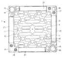
以下、本発明の実施の形態を図1乃至図4により説明する。図1は実施の形態による上部ノズルの平面図、図2は上部ノズルの側面図、図3は上部ノズルの中央縦断面図、図4は上部ノズルの上部部品と下部部品を分離した状態の斜視図である。
本発明の実施の形態による上部ノズル1は下部部品3と上部部品5をそれぞれ切削工具による機械加工によって予め別個に成形して、溶接によって接合して構成されている。
下部部品3は略四角形板状、例えば正方形板状のアダプタプレート7の四辺をなす側部に4枚の側板9…即ちエンクロージャが一体形成されて構成され、各側板9はアダプタプレート7の側部から上方に直角に起立して薄板状に形成されている。またアダプタプレート7は長穴形状のスロット10と制御棒クラスタ等の非核燃料炉心構成品を挿入するための穴11等が多数穿孔され、これらのスロット10や穴11等を冷却水等の冷却流体がスムーズに通過できるようになっている。
【0008】
また上部部品5は略四角形枠状、例えば正方形枠状のトッププレート13とその上面の4つの角部に突出形成された平面視略L字型の各一対のパッド部15,15及びクランプ部17,17とが設けられている。パッド部15はトッププレート13の一方の対角方向に対向配置され、案内ピン穴16が穿孔されている。
クランプ部17はトッププレート13の他方の対角方向に対向配置され、複数のホール18が穿孔されている。
また上部部品5と下部部品3とは図2及び図3に示すようにトッププレート13の下面13aと側板9の上端9aとで接合されて溶接部20を以て溶接されて一体化されており、溶接状態でトッププレート13と側板9とは好ましくは外面が同一平面状に形成されている。しかもトッププレート13の各辺をなす枠板13Aは側板9よりも厚みが大きく、そのために内面側ではトッププレート13と側板9との間に段差19が形成されている。換言すれば内面では側板9の面から枠板13Aが内側に突出しているともいえる。
トッププレート13の上部には各枠板13A上に各クランプ部17からパッド部15に向けて上方に傾斜する板状のスプリング21…が装着されている。
【0009】
本実施の形態による上部ノズル1は上述の構成を備えており、次に上部ノズル1の組立方法について説明する。
まずスチール等からなる正方形板状または直方体形状の図示しない素材ブロックをエンドミルやドリルやTスロットカッタ等の各種転削工具で切削加工して、アダプタプレート7が四枚の側板9…で囲われた形状を有する下部部品3を一体形状として削り出す。工作機械による切削加工に際して、素材ブロックを1回セッティングした状態で一方(上方)からアダプタプレート7及び側板9…を全て切削加工できる。
同様に別の素材ブロックを切削加工して四角枠形状をなすトッププレート13の上面角部に各一対のパッド部15、15及びクランプ部17,17を有する上部部品5を一体形状として削り出す。この場合も、工作機械による切削加工に際して、素材ブロックを1回セッティングした状態で一方(上方)から略角柱状の枠板13Aでなるトッププレート13及び各一対のパッド部15、15及びクランプ部17,17を切削加工できる。
【0010】
次に上部ノズル1の組立手順について説明すると、二分割状態で予め製造された下部部品3及び上部部品5を図4に示すように対向させて下部部品3の側板9の上端9aを上部部品5のトッププレート13の各枠板13Aの下面13aに当接させ、各側板9と枠板13Aの両外面が同一平面状になるように位置決めして接合部を溶接すればよい。
【0011】
上述のように本実施の形態によれば、下部部品3と上部部品5とはトッププレート13と側板9とで分離して各部品を構成することとしたから、各部品の機械加工に際して、下部部品3及び上部部品5とも各1回のセッティングで素材ブロックの片側のみから加工して成形できるため、製造工程が少なくて製造コストが低廉になる。しかも各部品3,5についてセッティングし直すことなくそれぞれ1回のセッティングで一気に加工できるから各部品及び部分の寸法精度及び加工精度が高い。また加工工数が双方の部品に配分され、複数台の工作機械で機械加工する場合、並行して加工できて効率的であり機械稼働率が良く、この点でも製造コストを低廉にすることができる。
これに対して上述の従来技術によれば、アダプタプレートを下側部品として残りを上側部品とした場合や、エンクロ−ジャの中央で分割して上側及び下側部品とした場合でも、上側部品を機械加工する際に、トッププレートの上側のパッド部やクランク部を切削する場合とトッププレートの枠板及び側板の一部の段差を切削する場合とで上面及び下面をそれぞれ加工するから2回セッティングする必要があり、これによって加工精度が低下するという欠点が生じる。
【0012】
【発明の効果】
以上説明したように、本発明に係る上部ノズルの製造方法は、機械加工によってそれぞれ成形された、トッププレート及びパッド部及びクランプ部を有する上部部品とアダプタプレート及びエンクロージャを有する下部部品とをトッププレートとエンクロージャで溶接して一体化してなるから、各部品の機械加工に際して、下部部品及び上部部品とも各1回のセッティングで素材ブロックの片側のみから加工して完全に成形でき、セッティングし直すことなく一気に加工できるから製造工程が少なくて製造コストが低廉で加工精度が高い。また加工工数が双方の部品に配分され、複数台の工作機械で機械加工する場合、並行して加工できて効率的であり機械稼働率が良く、この点でも製造コストを低廉にすることができる。
【0013】
またトッププレートはエンクロージャとの接合部の内面がエンクロージャの内面より突出して段差が設けられているから、段差の上下を切削加工すると両側でそれぞれ切削するために2回セッティングする必要があるが、段差の部分で分割して2部品としたためにそれぞれ片側からのみ切削加工すればよく加工のためのセッティングも各1回で済む。
【図面の簡単な説明】
【図1】 本発明の実施の形態による上部ノズルの平面図である。
【図2】 上部ノズルの側面図である。
【図3】 上部ノズルの中央縦断面図である。
【図4】 上部ノズルの上部部品と下部部品の分解斜視図である。
【符号の説明】
1 上部ノズル
3 下部部品
5 上部部品
7 アダプタプレート
9 側板(エンクロージャ)
13 トッププレート
13A 枠板
19 段差
20 溶接部[0001]
BACKGROUND OF THE INVENTION
The present invention relates to amethod of manufacturing an upper nozzle incorporated in a nuclear fuel assembly used in a nuclear reactor.
[0002]
[Prior art]
Conventionally, for example, a nuclear fuel assembly used in a pressurized water nuclear reactor has a plurality of support grids arranged at predetermined intervals between an upper nozzle and a lower nozzle, and an instrument tube and a plurality of control rod guide tubes are supported by each. A plurality of fuel rods are inserted and held in the lattice space of each support lattice, fixed to the lattice, the upper nozzle, and the lower nozzle, respectively.
The upper nozzle has an adapter plate having a substantially rectangular plate shape, an enclosure composed of four side walls surrounding the four sides of the adapter plate, and a top plate. At the upper four corners of the top plate, Each pair of pad portions and clamp portions are formed. In order to manufacture such an upper nozzle, the adapter plate, the enclosure, the top plate, the pad portion, and the clamp portion are each joined by welding.
However, since the upper nozzle obtained in this way has many welded portions, a test for confirming the soundness of each welded portion is necessary and complicated. In addition, there is a problem in the requirement of dimensional accuracy in the integral molding by a casting method or the like, and there is a problem that a defect of a cast product occurs.
[0003]
[Problems to be solved by the invention]
On the other hand, in Japanese Patent Laid-Open No. 3-255390, the adapter plate is used as the lower part and the other parts are pre-formed as the upper part, or divided into two in the horizontal direction at the central part of the enclosure. There have been proposed parts that are pre-formed as parts and joined together by welding. If manufactured in this manner, welding is only required at one joint between the upper part and the lower part, so that the manufacture is easy and the test for confirming the soundness of the welding is also simple.
However, in such a method for manufacturing the upper nozzle, when the upper part is manufactured by machining such as cutting, the inner surface of the top plate protrudes inward from the inner surface of the enclosure, so that a step is provided. There is a drawback in that the upper part has to be set upside down with respect to the machine tool in the process of machining the part and the clamp part and the process of machining the step, which is complicated and troublesome. In addition, there is a drawback that the machining accuracy is lowered by re-setting for machining the upper and lower parts of the upper part.
[0004]
The present invention has been made in view of such circumstances, and an object of the present invention is to provide amethod of manufacturing an upper nozzle that is easy to machine and has high machining accuracy.
[0005]
[Means for Solving the Problems]
The method of manufacturing the upper nozzle according to the present invention is such that an upper part having a top plate, a pad part and a clamp part, and a lower part having an adapter plate and an enclosure, which are respectively formed by machining, are welded together by the top plate and the enclosure. in the manufacturing method of theupper portion nozzlesing turned into,the upper parttop plate is provided with a stepped protruding from the inner surface of the inner surface of the joint enclosure with the lower part of the enclosure is divided in portions of the stepped When cuttingthe material block intotwo parts and cutting the lower part, the adapter plate and the enclosure are cut from the upper side with the material block set once, and another material block is cut. When cutting the upper part by machining And characterized in that as cutting integrally form the top plate and each pair pad portion and the clamping portion comprising a frame plateof rectangular cross section with a substantially prismatic from above while setting one another material block To do.
By dividing the lower part and the upper part into two parts by the top plate and the enclosure, each part is molded in a state of being divided by the top plate having a large thickness and the enclosure having a small thickness. At the time of processing, only one side of the material block can be processed by one setting for each of the lower part and the upper part, and can be completely formed in one setting state. Therefore, the processing accuracy of each part and part is high.
[0006]
The top plate may be provided with a step so that the inner surface of the joint with the enclosure protrudes from the inner surface of the enclosure.
When cutting the top and bottom of the step, it is necessary to set twice to cut each side, but in the present invention, since it is divided into two parts at the step part, there is no step in the upper and lower parts, Each of them only needs to be cut from one side, and the setting for the machining can be done only once.
[0007]
DETAILED DESCRIPTION OF THE INVENTION
Embodiments of the present invention will be described below with reference to FIGS. 1 is a plan view of an upper nozzle according to an embodiment, FIG. 2 is a side view of the upper nozzle, FIG. 3 is a central longitudinal sectional view of the upper nozzle, and FIG. 4 is a perspective view of the upper nozzle separated from the upper and lower parts. FIG.
The upper nozzle 1 according to the embodiment of the present invention is configured by separately forming a
The
[0008]
The upper part 5 has a substantially quadrangular frame shape, for example, a square frame-shaped
The
2 and 3, the upper part 5 and the
On top of the
[0009]
The upper nozzle 1 according to the present embodiment has the above-described configuration. Next, a method for assembling the upper nozzle 1 will be described.
First, a material block (not shown) having a square plate shape or a rectangular parallelepiped shape made of steel or the like is cut with various rolling tools such as an end mill, a drill, a T slot cutter, etc., and the
Similarly, another material block is cut and the upper part 5 having a pair of
[0010]
Next, the assembly procedure of the upper nozzle 1 will be described. The
[0011]
As described above, according to the present embodiment, the
On the other hand, according to the above-mentioned prior art, even when the adapter plate is the lower part and the rest is the upper part, or when the upper part and the lower part are divided at the center of the enclosure, When machining, the upper and lower surfaces are machined each time when cutting the upper pad and crank parts of the top plate and when cutting the top plate frame and part of the side plate. This has the disadvantage of reducing the machining accuracy.
[0012]
【The invention's effect】
As described above, themethod for manufacturing an upper nozzle according to the present invention includes a top plate having a top plate, a pad part, and a clamp part, and an adapter plate and a lower part having an enclosure, which are formed by machining. Since it is welded and integrated in the enclosure, when machining each part, the lower part and the upper part can be processed from only one side of the material block with one setting each and completely molded, without re-setting Since it can be processed at once, there are few manufacturing processes, manufacturing costs are low, and processing accuracy is high. In addition, when the machining man-hours are distributed to both parts and machined by multiple machine tools, they can be machined in parallel and are efficient, and the machine operating rate is good. In this respect as well, the manufacturing cost can be reduced. .
[0013]
In addition, the top plate has a step with the inner surface of the joint with the enclosure protruding from the inner surface of the enclosure, so if you cut the top and bottom of the step, you need to set it twice to cut each side. Since these parts are divided into two parts, it is only necessary to perform cutting from one side of each part, and the setting for the machining can be done only once.
[Brief description of the drawings]
FIG. 1 is a plan view of an upper nozzle according to an embodiment of the present invention.
FIG. 2 is a side view of an upper nozzle.
FIG. 3 is a central longitudinal sectional view of an upper nozzle.
FIG. 4 is an exploded perspective view of an upper part and a lower part of the upper nozzle.
[Explanation of symbols]
1
13
Claims (1)
Translated fromJapanese前記上部部品のトッププレートは前記下部部品のエンクロージャとの接合部の内面が前記エンクロージャの内面より突出して段差が設けられており、該段差の部分で分割して2部品とし、
素材ブロックを切削加工して下部部品を削り出す切削加工に際して、素材ブロックを1回セッティングした状態で上方からアダプタプレート及びエンクロージャを一体形状として切削加工すると共に、
別の素材ブロックを切削加工して上部部品を削り出す切削加工に際して、別の素材ブロックを1回セッティングした状態で上方から略角柱状で断面四角形の枠板でなるトッププレート及びパッド部及びクランプ部を一体形状として切削加工するようにした
ことを特徴とする上部ノズルの製造方法。Machined molded respectively by the manufacture ofthe upper part nozzle and the lower parting and integrated by welding at the top plate and the enclosure having an upper part and the adapter plate and the enclosure having a top plate and a pad portion and a clamping portion In the method
The top plate of the upper part has a step provided so that the inner surface of the joint with the enclosure of the lower part protrudes from the inner surface of the enclosure, and is divided into two parts by the step part.
Upon cutting the cut out the lower part by cutting the material block, the cutting integrally shapethe adapter plate andenclosure from above while setting once material block,
When cutting another material block and cutting the upper part, the top plate, pad portion, and clamp portionare formed froma frame plate having a substantially rectangular column shapeand a rectangular cross section from above with another material block set once. A method of manufacturing an upper nozzle, characterized in that cutting is performed as an integral shape.
Priority Applications (1)
| Application Number | Priority Date | Filing Date | Title |
|---|---|---|---|
| JP2000174388AJP4549493B2 (en) | 2000-06-09 | 2000-06-09 | Upper nozzle manufacturing method |
Applications Claiming Priority (1)
| Application Number | Priority Date | Filing Date | Title |
|---|---|---|---|
| JP2000174388AJP4549493B2 (en) | 2000-06-09 | 2000-06-09 | Upper nozzle manufacturing method |
Publications (2)
| Publication Number | Publication Date |
|---|---|
| JP2001349974A JP2001349974A (en) | 2001-12-21 |
| JP4549493B2true JP4549493B2 (en) | 2010-09-22 |
Family
ID=18676439
Family Applications (1)
| Application Number | Title | Priority Date | Filing Date |
|---|---|---|---|
| JP2000174388AExpired - LifetimeJP4549493B2 (en) | 2000-06-09 | 2000-06-09 | Upper nozzle manufacturing method |
Country Status (1)
| Country | Link |
|---|---|
| JP (1) | JP4549493B2 (en) |
Families Citing this family (3)
| Publication number | Priority date | Publication date | Assignee | Title |
|---|---|---|---|---|
| KR101859524B1 (en) | 2017-01-16 | 2018-05-23 | 한전원자력연료 주식회사 | Top nozzle provided with waved plate for nuclear fuel assembly |
| CN108907609B (en)* | 2017-12-27 | 2019-09-17 | 中核北方核燃料元件有限公司 | A kind of nuclear fuel assembly upper tube seat machining process and clamp for machining |
| CN108922642B (en)* | 2017-12-27 | 2019-09-17 | 中核北方核燃料元件有限公司 | A kind of ringed nucleus upper pipe seat of fuel component machining process and clamp for machining |
Family Cites Families (2)
| Publication number | Priority date | Publication date | Assignee | Title |
|---|---|---|---|---|
| JPH03255390A (en)* | 1990-03-05 | 1991-11-14 | Nuclear Fuel Ind Ltd | Upper nozzle for nuclear fuel assembly |
| FR2714762B1 (en)* | 1993-12-30 | 1996-03-15 | Framatome Sa | Fuel assembly of a nuclear reactor cooled by light water. |
- 2000
- 2000-06-09JPJP2000174388Apatent/JP4549493B2/ennot_activeExpired - Lifetime
Also Published As
| Publication number | Publication date |
|---|---|
| JP2001349974A (en) | 2001-12-21 |
Similar Documents
| Publication | Publication Date | Title |
|---|---|---|
| JP3722258B2 (en) | Punching device for punching, punch for punching, and method for manufacturing punch for punching | |
| JP6764036B2 (en) | Manufacturing method of battery module housing and battery module housing to which electromagnetic pulse bonding technology is applied | |
| JP6036555B2 (en) | Press mold | |
| US7918008B2 (en) | Method of manufacturing column and bed of machine tool | |
| JPH03205590A (en) | Filter plate associated with lower connector of fuel rod cluster in atomic reactor | |
| JP4549493B2 (en) | Upper nozzle manufacturing method | |
| JPH029551B2 (en) | ||
| KR101144069B1 (en) | Pencil support grid for nuclear fuel assembly and corresponding assembly | |
| JP2954151B1 (en) | Cask basket | |
| KR100598048B1 (en) | Composite press mold for manufacturing yoke of optical pickup device | |
| JP3170896U (en) | Laser processing jig | |
| JP3408380B2 (en) | Appearance inspection jig | |
| GB2062208A (en) | Plate heat exchanger | |
| KR101794091B1 (en) | Jig for processing graphite and method for processing graphite using the same | |
| CN218855930U (en) | Laser cutting clamp for titanium alloy stringer parts | |
| KR101937011B1 (en) | supporting device for mold | |
| CN221493852U (en) | Assembled flexible solder blanking die | |
| JP2573470Y2 (en) | Grating shearing machine | |
| JPH09271989A (en) | Manufacture of grating beam | |
| JPH067932A (en) | Manufacture of grating | |
| JPS6329617B2 (en) | ||
| JPH03255390A (en) | Upper nozzle for nuclear fuel assembly | |
| JP2002214377A (en) | Foreign matter trapping device for boiling water nuclear fuel assemblies | |
| KR20220167651A (en) | Jig for working multi faces of product | |
| JPH01178408A (en) | How to divide printed wiring boards |
Legal Events
| Date | Code | Title | Description |
|---|---|---|---|
| A621 | Written request for application examination | Free format text:JAPANESE INTERMEDIATE CODE: A621 Effective date:20070515 | |
| A977 | Report on retrieval | Free format text:JAPANESE INTERMEDIATE CODE: A971007 Effective date:20090205 | |
| A711 | Notification of change in applicant | Free format text:JAPANESE INTERMEDIATE CODE: A711 Effective date:20090605 | |
| A521 | Request for written amendment filed | Free format text:JAPANESE INTERMEDIATE CODE: A821 Effective date:20090605 | |
| A131 | Notification of reasons for refusal | Free format text:JAPANESE INTERMEDIATE CODE: A131 Effective date:20090721 | |
| A521 | Request for written amendment filed | Free format text:JAPANESE INTERMEDIATE CODE: A523 Effective date:20090917 | |
| A131 | Notification of reasons for refusal | Free format text:JAPANESE INTERMEDIATE CODE: A131 Effective date:20091201 | |
| A521 | Request for written amendment filed | Free format text:JAPANESE INTERMEDIATE CODE: A523 Effective date:20100201 | |
| TRDD | Decision of grant or rejection written | ||
| A01 | Written decision to grant a patent or to grant a registration (utility model) | Free format text:JAPANESE INTERMEDIATE CODE: A01 Effective date:20100629 | |
| A01 | Written decision to grant a patent or to grant a registration (utility model) | Free format text:JAPANESE INTERMEDIATE CODE: A01 | |
| A61 | First payment of annual fees (during grant procedure) | Free format text:JAPANESE INTERMEDIATE CODE: A61 Effective date:20100707 | |
| R150 | Certificate of patent or registration of utility model | Free format text:JAPANESE INTERMEDIATE CODE: R150 Ref document number:4549493 Country of ref document:JP Free format text:JAPANESE INTERMEDIATE CODE: R150 | |
| FPAY | Renewal fee payment (event date is renewal date of database) | Free format text:PAYMENT UNTIL: 20130716 Year of fee payment:3 | |
| R250 | Receipt of annual fees | Free format text:JAPANESE INTERMEDIATE CODE: R250 | |
| R250 | Receipt of annual fees | Free format text:JAPANESE INTERMEDIATE CODE: R250 | |
| R250 | Receipt of annual fees | Free format text:JAPANESE INTERMEDIATE CODE: R250 | |
| R250 | Receipt of annual fees | Free format text:JAPANESE INTERMEDIATE CODE: R250 | |
| R250 | Receipt of annual fees | Free format text:JAPANESE INTERMEDIATE CODE: R250 | |
| R250 | Receipt of annual fees | Free format text:JAPANESE INTERMEDIATE CODE: R250 | |
| R250 | Receipt of annual fees | Free format text:JAPANESE INTERMEDIATE CODE: R250 | |
| EXPY | Cancellation because of completion of term |