JP4547040B1 - Display image switching device and display image switching method - Google Patents
Display image switching device and display image switching methodDownload PDFInfo
- Publication number
- JP4547040B1 JP4547040B1JP2010044182AJP2010044182AJP4547040B1JP 4547040 B1JP4547040 B1JP 4547040B1JP 2010044182 AJP2010044182 AJP 2010044182AJP 2010044182 AJP2010044182 AJP 2010044182AJP 4547040 B1JP4547040 B1JP 4547040B1
- Authority
- JP
- Japan
- Prior art keywords
- camera
- image
- moving
- image information
- displayed
- Prior art date
- Legal status (The legal status is an assumption and is not a legal conclusion. Google has not performed a legal analysis and makes no representation as to the accuracy of the status listed.)
- Expired - Fee Related
Links
Images


Classifications
- H—ELECTRICITY
- H04—ELECTRIC COMMUNICATION TECHNIQUE
- H04N—PICTORIAL COMMUNICATION, e.g. TELEVISION
- H04N7/00—Television systems
- H04N7/18—Closed-circuit television [CCTV] systems, i.e. systems in which the video signal is not broadcast
- H04N7/181—Closed-circuit television [CCTV] systems, i.e. systems in which the video signal is not broadcast for receiving images from a plurality of remote sources
- H—ELECTRICITY
- H04—ELECTRIC COMMUNICATION TECHNIQUE
- H04N—PICTORIAL COMMUNICATION, e.g. TELEVISION
- H04N23/00—Cameras or camera modules comprising electronic image sensors; Control thereof
- H04N23/90—Arrangement of cameras or camera modules, e.g. multiple cameras in TV studios or sports stadiums
Landscapes
- Engineering & Computer Science (AREA)
- Multimedia (AREA)
- Signal Processing (AREA)
- Closed-Circuit Television Systems (AREA)
- Studio Devices (AREA)
Abstract
Translated fromJapaneseDescription
Translated fromJapanese本発明は、装着型カメラ等の移動カメラを複数用いて撮像された表示画像を切り替える表示画像切替装置及び表示画像切替方法に関する。The present invention relates to a display image switching device and a displayimage switching method for switching display images captured using a plurality of mobile cameras such as wearable cameras.
従来、金融機関の金庫、企業の重要機密の保管場所、銀行、ATM(automated teller machine)が設置されているコンビニエンス・ストア等の各種店舗では、設置した監視カメラが撮像した監視対象の動画像、静止画像を用いてセキュリティを維持している。 Conventionally, in various stores such as financial institution safes, corporate sensitive storage locations, banks, and convenience stores where ATMs (automated teller machines) are installed, moving images of surveillance objects captured by the installed surveillance cameras, Security is maintained using still images.
このような据置型のカメラを用いた撮像システムとして、特許文献1に開示の技術が知られている。特許文献1には、図1に示すように、各種店舗などを示す平面マップ上にカメラの位置、向き及び撮像範囲を示すカメラアイコンを表示し、表示されたカメラアイコンをユーザが選択すると、選択されたカメラによって撮像された画像を平面マップと並べて表示する技術が開示されている。 As an imaging system using such a stationary camera, a technique disclosed in
このような据置型のカメラを用いた防犯システムでは、カメラの撮像方向によっては監視対象者の人相、身長、服装等を十分に撮像できず、監視対象者の情報を十分に収集することができない。また、据置型のカメラを設置することが困難な屋外などのオープンスペースでは使用できない。このため、近年では、特許文献2に示すように、警備員、社員、店舗の店員等の身体(頭部、胸ポケット等)に装着型カメラを装着して、防犯場所を警備させ、警備した際に撮像した画像を用いて、不審者の監視を行うことが考えられている。 In such a crime prevention system using a stationary camera, depending on the imaging direction of the camera, it is not possible to sufficiently capture the human phase, height, clothes, etc. of the monitoring target person, and it is possible to collect sufficient information on the monitoring target person Can not. In addition, it cannot be used in open spaces such as outdoors where it is difficult to install a stationary camera. For this reason, in recent years, as shown in
また、特許文献3に開示された技術は、複数の移動型カメラを連携させ広範囲な領域を監視する場合に、移動型カメラの位置と撮影方向を管理することで同一の対象を撮影する複数の移動型カメラを抽出すると共に、複数の移動型カメラが撮影した対象を表示する、といった技術である。これにより、最も撮影状況のよいカメラから求めた位置情報をカメラ間で共有できるので、対象の追跡が容易になる。 In addition, the technique disclosed in
さらに、特許文献4に開示された技術は、ユーザの見たい地点を指定すると、その地点を一番早く撮影できるカメラを選択する、といった技術である。これにより、管理者は複数カメラが存在しても簡易な方法で見たい対象や地点を見ることができる。 Furthermore, the technique disclosed in Patent Document 4 is a technique in which, when a point that a user wants to see is specified, a camera that can photograph the point first is selected. Thereby, even if there are a plurality of cameras, the administrator can see a target or a point to be viewed with a simple method.
上述した特許文献2に開示された技術では、広範な領域を監視する場合、オペレータが複数の装着型カメラを制御して、監視領域又は監視対象を切り替えることが考えられる。しかしながら、複数のカメラから特定のカメラを選択する方法や、選択したカメラの撮像画像を切り替える方法について開示されておらず、そのような実現方法が不明である。 In the technique disclosed in
また、上述した特許文献1に開示された技術において、据置型カメラを装着型カメラに置き換えることは容易に考えられる。しかしながら、カメラアイコンが平面マップ上を自由に動くことになり、カメラの位置及び向きを考慮しながら、カメラを選択しなければならず、オペレータの負担が増大する。また、平面マップ上でカメラを選択し、選択したカメラの撮像画像を見るため、平面マップと撮像画像との間で視線移動が多くなり、この点においてもオペレータの負担が増大する。 In the technique disclosed in
また、特許文献3には、管理センターにおいて、平面マップ上にカメラの位置がマッピングされていることと、各カメラの映像を表示することは開示されているが、複数のカメラ画像から特定の画像を選択することや、選択したカメラ画像を切り替える方法についてついては開示されていない。
さらに、特許文献4に開示された技術では、監視者が地点を選択することと、選択された地点を一番早く撮影できるカメラを抽出することは開示されているが、監視者は対象や地点を選択した状態から対象を別の角度で見たいと考えた際には再度全体マップから地点や方向を選択する必要があり、簡易な手段で他のカメラへ切り替える方法は開示されていない。 Furthermore, in the technique disclosed in Patent Document 4, it is disclosed that the supervisor selects a spot and that a camera that can photograph the selected spot the earliest is extracted. When the user wants to view the object at a different angle from the state of selecting, it is necessary to select a point or direction from the entire map again, and a method for switching to another camera by simple means is not disclosed.
本発明の目的は、移動を伴う複数のカメラから特定のカメラを選択する際、直感的で分かりやすい選択方法を提供することで、オペレータの負担を軽減する表示画像切替装置及び表示画像切替方法を提供することである。An object of the present invention is to provide a display image switching device and a displayimage switching method that reduce an operator's burden by providing an intuitive and easy-to-understand selection method when a specific camera is selected from a plurality of cameras with movement. Is to provide.
本発明の表示画像切替装置の一つの態様は、複数の移動カメラのうち、第1の移動カメラによって撮像された画像を表示させる画像選択手段と、前記表示された画像の中から対象を選択する対象選択手段と、前記複数の移動カメラから、前記対象選択手段によって選択された前記対象を撮影する移動カメラを、第2の移動カメラとして抽出するカメラ抽出手段と、前記第2の移動カメラの前記表示された画像上での位置を算出するカメラ位置算出手段と、前記第2の移動カメラの位置を示し選択可能なカメラ位置画像情報を生成するカメラ位置画像情報生成手段と、を具備し、前記カメラ位置画像情報生成手段は、前記カメラ位置画像情報を前記画像選択手段で選択されている画像と関連付けて表示し、前記画像選択手段は、前記カメラ位置画像情報が選択された場合、第2の移動カメラによって撮影された画像を表示する。One embodiment of the display image switching apparatus of the present invention,among the plurality of mobile camera,selects an image selection means for displaying the image captured by the firstmoving camera,the subject from among the displayed image A target selecting means; a camera extracting means for extracting a moving camera that captures the target selected by the target selecting means from the plurality of moving cameras as a second moving camera; and the second moving camera. Camera position calculating means for calculating a position on the displayed image; and camera position image information generating means for generatingselectable camera position image informationindicating the position of the second moving camera, and camera position image information generating means, the camera position image informationdisplayed in association with the image selected by the image selectingunit, said image selection means, the camera position If the image information is selected, it displays the image taken by the second moving camera.
本発明の表示画像切替方法の一つの態様は、複数の移動カメラのうち、第1の移動カメラによって撮像された画像を表示させる画像選択ステップと、前記表示された画像の中から対象を選択する対象選択ステップと、前記複数の移動カメラから、選択された前記対象を撮影している移動カメラを第2の移動カメラとして抽出するカメラ抽出ステップと、前記第2の移動カメラの位置を算出するカメラ位置算出ステップと、前記第2の移動カメラの位置を示し選択可能なカメラ位置画像情報を生成するカメラ位置画像情報生成ステップと、を具備し、前記カメラ位置画像情報生成ステップは、前記カメラ位置画像情報を前記画像選択ステップで選択されている画像と関連付けて表示し、前記画像選択ステップは、前記カメラ位置画像情報が選択された場合、第2の移動カメラによって撮影された画像を表示する。One aspect of the displayimage switching method of the present invention isan image selection step of displaying an image captured by a first moving camera among aplurality of moving cameras, and selecting a target from the displayed images. A target selection step; a camera extraction step of extracting, from the plurality of moving cameras, a moving camera that is photographing the selected target as a second moving camera; and a camera that calculates the position of the second moving camera A position calculating step; and a camera position image information generating step for generating selectable camera position image information indicating the position of the second moving camera, wherein the camera position image information generating step includes: Information is displayed in association with the image selected in the image selection step, and the image selection step is selected by the camera position image information. If it is, it displays the image taken by the second moving camera.
本発明によれば、移動を伴う複数のカメラから特定のカメラを、直感的で分かりやすく選択できるので、オペレータの負担を軽減することができる。 According to the present invention, since a specific camera can be selected intuitively and easily from a plurality of cameras accompanying movement, the burden on the operator can be reduced.
以下、本発明の実施の形態について、図面を参照して詳細に説明する。 Hereinafter, embodiments of the present invention will be described in detail with reference to the drawings.
本発明の装着型カメラは、例えば、イベント会場、展示会会場、駅構内、金融機関の金庫、企業の重要機密の保管場所、銀行、百貨店、コンビニエンス・ストア等の各種店舗や会場を警備する複数の撮像者(警備員、社員、店舗の店員等)の身体(頭部、胸ポケット等)に装着されて用いられる。特に据置型カメラの設置が困難な屋外イベント会場などのオープンスペースで有用である。 The wearable camera of the present invention can be used to guard various stores and venues such as event venues, exhibition venues, station premises, financial institution safes, important corporate confidential storage locations, banks, department stores, and convenience stores. Used on the body (head, chest pocket, etc.) of the photographer (security guard, employee, store clerk, etc.). This is especially useful in open spaces such as outdoor event venues where it is difficult to install stationary cameras.
なお、装着型カメラは必ずしも人に装着される必要はなく、人が持ち運びしながら撮像したり、自律走行可能なロボットに取り付けられたりしてもよい。すなわち、装着型カメラは移動カメラと言い換えることができる。 The wearable camera is not necessarily worn by a person, and may be taken while being carried by a person or attached to a robot capable of autonomous running. That is, the wearable camera can be rephrased as a moving camera.
(実施の形態1)
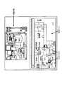
図2は、本発明の実施の形態1に係る監視システムの概要を説明する概念図である。ここでは、複数の装着型カメラ(以下、単に「カメラ」という)によって撮像された画像等が集中管理され、例えば、警備室等において監視員などのオペレータが視認する監視画面に表示される様子を例に説明する。各カメラにはID(カメラID)が付与されている。図2において、監視画面10の右側には、各種店舗などの監視領域を示す平面マップ11が表示され、警備員に装着されたカメラの位置及びカメラの視野が警備員を示す警備員アイコンと共に平面マップ11上に表示される。図2では、それぞれカメラID=2,5,6,7,8のカメラが存在している。(Embodiment 1)
FIG. 2 is a conceptual diagram illustrating an overview of the monitoring system according to
一方、監視画面10の左側には、オペレータが選択したカメラによって撮像されたカメラ画像12が表示される。図2では、楕円表示した領域に撮像画像を表示するが、楕円表示に限らず、円形表示でも、方形表示でもよい。 On the other hand, on the left side of the monitoring screen 10, a camera image 12 captured by the camera selected by the operator is displayed. In FIG. 2, the captured image is displayed in the oval display area, but is not limited to the oval display, and may be a circular display or a square display.
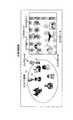
図2(a)は、カメラID=8のカメラによって撮像された画像が監視画面10の左側のカメラ画像12に表示されており、オペレータがある対象13(ここでは、枠で囲んだ人物)をポインタ14を用いて選択している様子を示している。 In FIG. 2A, an image captured by a camera with camera ID = 8 is displayed on the camera image 12 on the left side of the monitoring screen 10, and an object 13 (here, a person surrounded by a frame) is shown by an operator. A state of selection using the
本監視システムは、オペレータがある対象を選択すると、選択された対象を撮像しているカメラを抽出し、抽出したカメラが存在することを示すアイコンを、当該カメラを装着した警備員の近くに表示する。この様子を図2(b)に示す。ここでは、カメラID=2を表すカメラアイコン15をカメラ画像12に表示された警備員16の近くに表示する。このとき、撮像画像の表示領域に入らないカメラが抽出された場合、撮像画像の表示領域外に警備員を示す人物アイコンとカメラアイコンとを表示する。図2(b)では、カメラID=5を表すカメラアイコン17と警備員を示す人物アイコン18とを表示し、カメラID=6を表すカメラアイコン19と警備員を示す人物アイコン20とを表示する。このような表示をすることにより、オペレータは選択可能なカメラが監視空間内のどこにあるか直感的に理解することができる。 When the operator selects a target, the monitoring system extracts a camera that captures the selected target, and displays an icon indicating that the extracted camera is present near the security guard wearing the camera. To do. This is shown in FIG. Here, a
また、警備員を示す人物アイコンとカメラアイコンとを表示す際、人物アイコンの大きさをカメラID=8のカメラと当該警備員との距離に応じて変えてもよく、この距離が近ければ人物アイコンを大きく表示し、この距離が遠ければ人物アイコンを小さく表示する。なお、カメラ画像12の表示領域に入るか否かにかかわらず、カメラアイコンの表示についても、同様に距離に応じて大きさを変えてもよい。 Further, when displaying a person icon and a camera icon indicating a security guard, the size of the person icon may be changed according to the distance between the camera with camera ID = 8 and the security guard. The icon is displayed in a large size, and if the distance is long, the person icon is displayed in a small size. Regardless of whether or not the display area of the camera image 12 is entered, the size of the display of the camera icon may be similarly changed according to the distance.
また、カメラの撮像方向が分かるように人物アイコン又はカメラアイコンを表示してもよい。例えば、カメラの撮像方向を示す矢印を表示したり、方向別に複数のアイコンを用意しておいて、撮像方向に応じてアイコンを変更したりすることにより、アイコン表示されているカメラの撮像方向を視覚的に認識することができる。また、カメラアイコンにカメラIDの情報を重畳して表示してもよい。 Further, a person icon or a camera icon may be displayed so that the imaging direction of the camera can be understood. For example, by displaying an arrow indicating the imaging direction of the camera, or by preparing a plurality of icons for each direction and changing the icon according to the imaging direction, the imaging direction of the camera indicated by the icon is displayed. Can be visually recognized. Further, the camera ID information may be superimposed on the camera icon.
なお、撮像画像に映っている警備員であっても、その警備員のカメラが選択された対象を撮像していない場合は抽出されず、カメラアイコンは表示しない。すなわち、図2(b)では、カメラID=7のカメラは抽出されていないので、このカメラを装着した警備員21はカメラ画像12に映っているがカメラアイコンは表示しない。 Note that even a security guard appearing in a captured image is not extracted and the camera icon is not displayed if the security guard's camera does not capture the selected target. That is, in FIG. 2B, since the camera with the camera ID = 7 has not been extracted, the
図2(b)において、オペレータが監視画面左側のカメラ画像12においてカメラID=5のカメラアイコン17を選択すると、監視画面左側のカメラ画像12がカメラID=5のカメラ画像12に切り替わる。撮像画像が切り替わった様子を図2(c)に示す。このとき、図2(a)において選択された対象が選択された状態を継続し、対象を撮像しているカメラのアイコンを表示してもよいし、選択を解除して対象を再度選択できる状態にしてもよい。 In FIG. 2B, when the operator selects the
これにより、オペレータは監視画面10を見ながら、アイコンを選択するという直感的で分かりやすい簡単な操作で見たいカメラを直感的に切り替えることができる。また、カメラの切り替えに際して平面マップ11を参照する必要がないため、視線移動によるオペレータの負担を軽減し、オペレータの興味ある対象を連続的に表示することができる。さらに、対象の監視に適したカメラのみをアイコン表示するため、カメラを切り替えることができ、操作性の向上を図ることができる。特に、興味のある対象を様々な角度から監視する場合に有効である。 As a result, the operator can intuitively switch the camera he / she wants to see with an easy and intuitive operation of selecting an icon while viewing the monitoring screen 10. In addition, since it is not necessary to refer to the planar map 11 when switching cameras, it is possible to reduce the burden on the operator due to line-of-sight movement and to continuously display objects of interest to the operator. Furthermore, since only icons suitable for target monitoring are displayed as icons, the cameras can be switched, and operability can be improved. This is particularly effective when monitoring an object of interest from various angles.
なお、従来技術で示したように、監視画面10右側の平面マップ11上の警備員アイコンをオペレータがポインタ14を用いて指定することにより、監視画面10左側のカメラ画像12を切り替えるようにしてもよい。 As shown in the prior art, the camera image 12 on the left side of the monitoring screen 10 may be switched by the operator specifying the guard icon on the plane map 11 on the right side of the monitoring screen 10 using the
図3は本発明の実施の形態1に係る監視システム100の構成を示すブロック図である。以下、図3を参照しながら監視システム100の各部構成について説明する。 FIG. 3 is a block diagram showing the configuration of the
カメラ101は、実空間での自カメラの位置と、自カメラが向いている撮像方向とを測位して位置情報及び方向情報として取得する。位置情報の取得は、例えば、GPS(Global Positioning System)又は無線タグを用いて行われる。また、方向情報の取得は、例えば、ジャイロ、地磁気センサ又は位置が既知のランドマークを用いて行われる。また、カメラ101は、レンズを介して入射する被写体光を光電変換して撮像信号にするCMOS又はCCD等の撮像素子を有し、撮像した画像を所定の処理を施して画像データに加工する。また、カメラ101には、それぞれ異なるカメラIDが付与されている。さらに、カメラ101は、取得した画像データ及びカメラIDを無線通信によって画像管理サーバ102に送信し、カメラID、位置情報及び方向情報を無線通信によって位置管理サーバ103に送信する。なお、カメラ101のレンズの光軸方向をカメラの撮像方向とする。 The
画像管理サーバ102は、カメラ101から送信されたカメラIDと画像データを受信及び蓄積し、カメラごとの画像データをカメラIDと対応付けて管理し、蓄積した画像データを必要に応じて画像選択部106に出力する。 The
位置管理サーバ103は、カメラ101から送信されたカメラID、位置情報及び方向情報を受信及び蓄積し、カメラごとの位置情報及び方向情報をカメラIDと対応付けて管理し、蓄積した位置情報及び方向情報を必要に応じてカメラ抽出部108及びカメラ位置算出部109に出力する。 The
表示画像切替部104は、カメラ選択部105、画像選択部106、対象選択部107、カメラ抽出部108、カメラ位置算出部109、カメラアイコン配置部110を有する。 The display image switching unit 104 includes a
カメラ選択部105は、カメラ101によって撮像された画像(図2(a)では監視画面10左側に表示されたカメラ画像12)に重ねて表示されたカメラアイコンをオペレータが選択したり、後述する表示部111に表示された平面マップ(図2に示した監視画面10右側に表示された画像)上に示されるアイコンをオペレータが選択したりすると、どのカメラが選択されたかを示すカメラ選択情報(例えば、カメラID)を画像選択部106に出力する。ここで、カメラ101によって撮像された画像に重ねて表示されたカメラアイコンをオペレータが選択する処理として次のような処理が考えられる。すなわち、オペレータがマウスなどのポインタを用いて画面上の座標を入力すると、カメラ選択部105は、入力された座標に対応するアイコンと、そのアイコンに対応するカメラIDとを後述するカメラアイコン配置部110から求めることが考えられる。また、表示部111に表示された平面マップ上に示されるカメラをオペレータが選択する処理として、具体的には、平面マップ上で選択されたカメラの位置情報に対応するカメラIDを図示せぬ信号線を介して位置管理サーバ103から取得することが考えられる。 The
画像選択部106は、カメラ選択部105から出力されたカメラ選択情報に基づいて、対応するカメラ101の画像データを画像管理サーバ102から読み出し、読み出した画像データを対象選択部107及び表示部111に出力する。また、画像選択部106は、カメラ選択部105から出力されたカメラ選択情報を対象選択部107に出力する。 Based on the camera selection information output from the
対象選択部107は、カメラ選択部105が選択したカメラ101によって撮像された画像内に存在する人物、物体などの対象をオペレータが選択すると、画像選択部106から出力された画像データに基づいて、選択された対象を示す対象選択情報を生成してカメラ抽出部108に出力する。また、対象選択部107は、カメラ選択部105が選択したカメラ101のカメラIDを取得し、カメラ抽出部108に出力する。なお、対象選択情報は、オペレータが選択した対象の画面上の座標である。 When the operator selects a target such as a person or an object existing in the image captured by the
カメラ抽出部108は、対象選択部107から出力された対象選択情報及び画像データ、カメラ選択部105が選択したカメラ101のカメラID及び位置管理サーバ103から取得したカメラの位置情報及び方向情報に基づいて、対象を撮像しているカメラ101を抽出し、抽出したカメラ101のカメラIDをカメラ位置算出部109に出力する。なお、具体的なカメラ抽出処理については後述する。 The
カメラ位置算出部109は、カメラ抽出部108から出力されたカメラIDに対応する位置情報を位置管理サーバ103から読み出し、読み出した位置情報を用いて、表示部111に表示されている画像上での位置を算出する。算出された画像上での位置(座標)はカメラIDと共にカメラアイコン配置部110に出力される。 The camera
カメラアイコン配置部110は、カメラアイコンとカメラIDとを対応付けて管理し、カメラ位置算出部109によって算出された画像上での位置の近くにカメラアイコンを配置する。なお、カメラ位置算出部109及びカメラアイコン配置部110は、抽出されたカメラの位置を示す画像情報を生成するカメラ位置画像情報生成手段として機能する。 The camera
表示部111は、画像選択部106によって選択された画像にカメラアイコン配置部110によって配置されたカメラアイコンを重ねて表示する。なお、表示部111は、図2に示した監視画面10を表示する。 The
このようにして表示されたカメラアイコンは、撮像者である警備員の移動に伴って、画面上を移動するものとする。すなわち、処理を一定のタイミングで更新することによって、カメラ101の位置とアイコンの位置とがリンクし、カメラアイコンがカメラ101の動きに連動するようになる。また、警備員の移動により、抽出されたカメラが選択された対象を撮像しなくなった場合には、カメラアイコンは画面上から消去されるようになる。 The camera icon displayed in this manner is assumed to move on the screen in accordance with the movement of the guard who is the photographer. That is, by updating the process at a certain timing, the position of the
図4は、図3に示したカメラ抽出部108におけるカメラ抽出処理の手順を示すフロー図である。図4に示すステップS1において、カメラ抽出部108は、対象選択部107によって選択された対象の、表示部111に表示されている画像上における位置(対象選択情報)を取得する。 FIG. 4 is a flowchart showing a procedure of camera extraction processing in the
ステップS2では、カメラ抽出部108は、ステップS1において取得した対象の画像上の位置を用いて、対象の実空間における位置を算出する。 In step S2, the
ステップS3では、カメラ抽出部108は、位置管理サーバ103に蓄積されている全カメラ101の位置情報及び方向情報を取得する。 In step S <b> 3, the
ステップS4では、ステップS3において取得した全カメラ101の位置情報及び方向情報を用いて、カメラ抽出部108は、全カメラ101のうち、カメラ及び対象間の直線と当該カメラの光軸とがなす角度が一定の範囲内の全てのカメラを抽出する。このとき、一定の範囲=画角であれば、対象を撮像しているカメラが抽出される。また、一定の範囲<画角であれば、対象を画面の中心付近で撮像しているカメラが抽出される。これは、カメラの撮像範囲の端に対象が位置すると、表示された対象が見づらかったり、レンズの歪みによって対象が見づらく表示されたりすることが考えられるため、一定の範囲をさらに限定することにより、画面の中央付近で対象を撮像しているカメラを抽出し、監視に適した画像を得るようにした。 In step S4, using the position information and direction information of all the
また、カメラ及び対象の距離が一定の範囲内のカメラを抽出するという条件を付加してもよい。この条件を付加することにより、対象との距離が遠いカメラが抽出されることを回避することができ、近い距離から鮮明に対象を撮像しているカメラだけを抽出することができる。 Moreover, you may add the conditions that the camera and distance of an object extract the camera in a fixed range. By adding this condition, it is possible to avoid the extraction of a camera that is far from the object, and it is possible to extract only the camera that is capturing the object clearly from a short distance.
ステップS5では、ステップS4において抽出されたカメラ101のカメラIDをカメラ位置算出部109に出力する。 In step S5, the camera ID of the
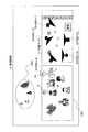
ここで、上記ステップS2における対象の実空間における位置算出方法について説明する。対象の実空間上の位置はある基準(ここでは、選択されているカメラ101)に対する方向と距離によって求まる。よって、まず、対象の方向の求め方について説明する。 Here, the position calculation method in the real space of the object in step S2 will be described. The position of the target in real space is determined by the direction and distance with respect to a certain reference (here, the selected camera 101). Therefore, first, how to obtain the target direction will be described.
図5に示すように、選択されているカメラ101の位置をO、画像内における光軸との交点をA、オペレータによって選択された対象の位置をT、予め位置が知られているランドマークの位置をLとする。カメラ101は、搭載されたジャイロを用いて、光軸OAの実空間での方向を取得することができ、その値を極座標系の2つの偏角を用いて(θ、φ)とする。 As shown in FIG. 5, the position of the selected
ここで、カメラ101のレンズ特性に基づいて、図6に示すような、画像内における座標(画像内座標)と、光軸を始線とする偏角とが対応付けられている場合、対象の画像内座標が分かると、∠AOTが一意に分かる。例えば、対象の画像内座標が(a0,b0)であるとすると、∠AOTは(θ0,φ0)と分かる。Here, based on the lens characteristics of the
よって、カメラ101の位置Oから対象までのベクトルOTの実空間での方向は、光軸OAの実空間での方向に∠AOTを加えた(θ+θ0,φ+φ0)と求めることができる。Therefore, the direction in the real space of the vector OT from the position O of the
ここで、対象の画像内座標として、画像内の対象を含む最小の方形の枠を配置し、配置した方形枠の一つの頂点の座標を用いたり、対象の輝度分布から最も明るい点などの特徴点における座標を用いたりすることが考えられる。要は、対象を表す任意の一点の座標であればよい。 Here, as the coordinates in the target image, the smallest square frame including the target in the image is placed, and the coordinates of one vertex of the placed rectangular frame are used, or the features such as the brightest point from the target luminance distribution It is conceivable to use coordinates at points. In short, the coordinates of an arbitrary point representing the target may be used.
また、カメラ101がジャイロを搭載しないなど、ジャイロを用いない場合における対象の方向の求め方について説明する。例えば、画像上に予め実空間での位置が知られているランドマークが存在する場合、このランドマークを用いて対象の方向を求めることもできる。具体的には、ランドマークの実空間での位置を絶対座標(X1,Y1,Z1)とし、カメラ101の実空間での位置を絶対座標(X0,Y0,Z0)とすると、極座標の変換式を用いて線分OLの実空間での方向は以下のように求められる。
そして、ランドマークの画像内座標(a1,b1)から光軸との偏角∠LOAは図6より(θ1,φ1)と分かるので、光軸OAの実空間での方向は以下のように求められる。
よって、ジャイロを用いた場合と同様に、カメラ101から対象までの方向ベクトルOTを求めることができる。なお、ランドマークの画像内座標は、上述した対象の画像内座標の求め方と同様とする。 Therefore, the direction vector OT from the
次に、カメラ101と対象との距離の算出方法について説明する。対象の実空間での大きさが分かっていれば、カメラ101のレンズ特性に基づいて、図7に示すような、画像内における対象の領域サイズと、対象までの距離とが対応付けられている場合、対象の画像内における領域サイズが分かると、対象までの距離が一意に分かる。なお、対象の画像内の領域サイズとして、画像内の対象を含む最小の方形の枠を配置し、配置した方形枠の幅及び高さによって表すことが考えられる。 Next, a method for calculating the distance between the
この対応付けは、対象が人物であるとして、実験やカメラ特性からの計算などで予め求めておけばよい。対象が人物以外の物体や動物の場合でも、その一般的な大きさをもとにした画像内の対象の領域サイズと対象までの距離との対応付けをとることができる。 This association may be obtained in advance by experiments or calculations from camera characteristics, assuming that the target is a person. Even when the target is an object other than a person or an animal, it is possible to associate the target area size in the image with the distance to the target based on the general size.
ここで、例えば、図8に示すように、対象の画像内における領域サイズが(幅、高さ)=(a_i,b_i)とすると、図7に示す表から対象までの距離がr_iと分かる。 Here, for example, as shown in FIG. 8, if the region size in the target image is (width, height) = (a_i, b_i), the distance from the table shown in FIG. 7 to the target is known as r_i.
このように、カメラ101に対する対象の方向及び距離を求めることにより、対象の実空間での位置を特定することができ、カメラ抽出部108は、求めた対象の実空間での位置を用いて、対象を撮像しているカメラ101を抽出する。 Thus, by obtaining the direction and distance of the object with respect to the
なお、カメラ位置算出部109におけるカメラ位置算出処理については、カメラ抽出処理のステップS1、ステップS2を逆に行えばよい。具体的には、抽出されたカメラと撮像しているカメラの実空間上の位置から、撮像しているカメラから抽出されたカメラへの方向を求める。次に、図6に示す対応表からその方向に対応する画像内座標を求めることができる。 Regarding the camera position calculation process in the camera
カメラ抽出部108の処理ステップS1からステップS4では、位置情報を用いてカメラIDを抽出したが、カメラ抽出部108のカメラ抽出処理に画像認識を用いることもできる。選択された対象の特徴情報を、画像認識を用いて計算し、画像管理サーバ102が保持する他カメラの画像中に、選択された対象と同じ特徴情報を含むか否かを判定する。特徴情報を含む画像を撮像しているカメラは、選択された対象を撮像しているカメラであると判定することができる。この方法は、カメラの位置情報や撮像方向の測位精度が悪い場合に用いか、または、カメラの位置情報及び方向情報と併用するとよい。 In processing steps S1 to S4 of the
このように実施の形態1によれば、複数の装着型カメラのうち、選択された装着型カメラによって撮像され、画面に表示された画像においてオペレータが対象を選択すると、選択された対象を撮像している他の装着型カメラを抽出し、抽出された装着型カメラの画像上の位置にカメラアイコンを表示し、表示されたカメラアイコンを選択すると、選択されたカメラアイコンに対応する装着型カメラによる撮像画像を画面に表示する。 As described above, according to the first embodiment, when the operator selects a target in the image captured by the selected wearable camera among the plurality of wearable cameras and displayed on the screen, the selected target is captured. The other wearable camera is extracted, a camera icon is displayed at the position on the extracted wearable camera image, and when the displayed camera icon is selected, the wearable camera corresponding to the selected camera icon is selected. The captured image is displayed on the screen.
これにより、オペレータは監視画面を見ながら、アイコンを選択するという直感的で分かりやすい簡単な操作で見たいカメラを直感的に切り替えることができる。また、カメラの切り替えに際して平面マップを参照する必要がないため、視線移動によるオペレータの負担を軽減し、オペレータの興味ある対象を連続的に表示することができる。さらに、対象の監視に適したカメラのみをアイコン表示するため、カメラを切り替えることができ、操作性の向上を図ることができる。 As a result, the operator can intuitively switch the camera he / she wants to see while selecting the icon while viewing the monitoring screen. In addition, since it is not necessary to refer to the plane map when switching the camera, it is possible to reduce the burden on the operator due to the movement of the line of sight and to continuously display objects of interest to the operator. Furthermore, since only icons suitable for target monitoring are displayed as icons, the cameras can be switched, and operability can be improved.
なお、本実施の形態では、監視画面に平面マップを表示するものとして説明したが、本発明はこれに限らず、平面マップを表示せず、選択されたカメラによる撮像画像を監視画面に表示するようにしてもよい。 In the present embodiment, the planar map is displayed on the monitoring screen. However, the present invention is not limited to this, and the captured image from the selected camera is displayed on the monitoring screen without displaying the planar map. You may do it.
また、本実施の形態では、抽出されたカメラをカメラアイコンによって明示するものとして説明したが、本発明はこれに限らず、抽出されたカメラを明示するアイコンであればよく、さらには、アイコンを表示する代わりに、抽出されたカメラを装着する警備員の表示色を反転させるなど表示色を変更してカメラを明示するようにしてもよい。要は、抽出されたカメラを選択可能に監視画面に表示できればよい。 In the present embodiment, the extracted camera is described as being clearly indicated by the camera icon. However, the present invention is not limited to this, and any icon that clearly indicates the extracted camera may be used. Instead of displaying, the camera may be clearly indicated by changing the display color, such as inverting the display color of the security guard wearing the extracted camera. In short, it is only necessary that the extracted camera can be displayed on the monitoring screen in a selectable manner.
(実施の形態2)
実施の形態1では、オペレータが選択した対象を撮像しているカメラのカメラアイコンを表示する場合について説明したが、本実施の形態では、カメラを抽出する条件として監視画面の左側に表示されているカメラ画像中に撮像されているカメラを抽出することとし、抽出されたカメラアイコンを表示する場合について説明する。(Embodiment 2)
In the first embodiment, the case where the camera icon of the camera that captures the target selected by the operator is displayed has been described. In the present embodiment, the camera is displayed on the left side of the monitoring screen as a condition for extracting the camera. A case will be described in which a camera imaged in a camera image is extracted and the extracted camera icon is displayed.
図9は、本発明の実施の形態2に係る監視システムの概要を説明する概念図である。この例では、カメラID=8のカメラ画像が現在表示されており、このカメラID=8のカメラの撮像範囲にはカメラID=2とカメラID=7のカメラが含まれている。また、カメラID=2を表すカメラアイコン15がカメラ画像12に表示された警備員16の近くに表示され、カメラID=7を表すカメラアイコン22がカメラ画像12に表示された警備員21の近くに表示されている。ここで、カメラID=2又はカメラID=7のカメラアイコンをオペレータが選択すると、監視画面左側のカメラ画像12は選択されたカメラIDのカメラ画像に切り替わる。 FIG. 9 is a conceptual diagram illustrating an overview of a monitoring system according to
図10は、本発明の実施の形態2に係る監視システム200の構成を示すブロック図である。ただし、図10において、実施の形態1の図3と共通する部分には、図3と同一の符号を付し、重複する説明は省略する。図10が図3と異なる点は、対象選択部107を削除し、カメラ抽出部108をカメラ抽出部201に変更した点である。 FIG. 10 is a block diagram showing the configuration of the
カメラ抽出部201は、カメラ選択部105から現在表示されているカメラ画像のカメラIDを取得し、取得したカメラIDに対応するカメラ101の位置情報及び方向情報を位置管理サーバ103から取得する。また、カメラ抽出部201は、位置管理サーバ103に蓄積されている全カメラ101の位置情報及び方向情報を取得し、現在表示されている画像を撮像しているカメラ101の位置情報及び方向情報と、全カメラ101の位置情報及び方向情報とに基づいて、現在表示されている画像を撮像しているカメラ101の撮像範囲に含まれる他のカメラ101を抽出する。 The
なお、監視システム200は、現在表示されている撮像画像の画像処理を行い、カメラ101を装着する警備員を画像認識で抽出し、該当位置にカメラアイコンを表示してもよい。 The
このように実施の形態2によれば、複数の装着型カメラのうち、画面に表示された画像に含まれる他の装着型カメラを抽出し、抽出された装着型カメラの画像上の位置にカメラアイコンを表示することにより、簡単な操作で監視画像を切り替えることができ、操作性の向上を図ることができる。 As described above, according to the second embodiment, among the plurality of wearable cameras, another wearable camera included in the image displayed on the screen is extracted, and the camera is positioned on the extracted image of the wearable camera. By displaying the icon, the monitoring image can be switched by a simple operation, and the operability can be improved.
(実施の形態3)
上述の実施の形態1、2では全てのカメラが装着型カメラである場合の例を示しが、本発明は、全てのカメラが装着型カメラでなく一部に据置型カメラがある場合でも有効である。本実施の形態では、その場合の例について説明する。(Embodiment 3)
In the first and second embodiments described above, an example is shown in which all cameras are wearable cameras. However, the present invention is effective even when all cameras are not wearable cameras and some have stationary cameras. is there. In this embodiment, an example in that case will be described.
本実施の形態では、実施の形態2におけるカメラID=7のカメラが据置型の場合について説明する。 In this embodiment, a case where the camera with camera ID = 7 in the second embodiment is a stationary type will be described.
図11は、本発明の実施の形態3に係る監視システムの概要を説明する概念図である。この例では、カメラID=8のカメラ画像が現在表示されており、このカメラID=8のカメラの撮像範囲にはカメラID=2の装着型カメラとカメラID=7の据置型カメラが含まれている。また、カメラID=2に対応する移動型カメラであることを示すカメラアイコン15(丸型のアイコン)がカメラ画像12に表示された警備員16の近くに表示され、カメラID=7に対応する据置型カメラを表すカメラアイコン22(四角型のアイコン)がカメラ画像12に表示された監視カメラ21の近くに表示されている。 FIG. 11 is a conceptual diagram illustrating an overview of a monitoring system according to
オペレータは、これらのアイコンを参照することで、装着型カメラか据置型カメラかを区別して認識できる。 The operator can distinguish and recognize whether the camera is a wearable camera or a stationary camera by referring to these icons.
ここで、カメラID=2又はカメラID=7のカメラアイコンをオペレータが選択すると、監視画面左側のカメラ画像12は選択されたカメラIDのカメラ画像に切り替わる。 When the operator selects a camera icon with camera ID = 2 or camera ID = 7, the camera image 12 on the left side of the monitoring screen is switched to the camera image with the selected camera ID.
図12は、本発明の実施の形態3に係る監視システム300の構成を示すブロック図である。ただし、図12において、実施の形態2の図10と共通する部分には、図10と同一の符号を付し、重複する説明は省略する。図12が図10と異なる点は、カメラ101として、装着型カメラ301と据置型カメラ302の2種類がある点、位置管理サーバ103を位置管理サーバ303に、カメラアイコン配置部110をカメラアイコン配置部304に変更した点である。 FIG. 12 is a block diagram showing a configuration of
位置管理サーバ303は、カメラ101から送信されたカメラID、位置情報及び方向情報に加えて、カメラ101が装着型カメラ301か据置型カメラ302であるかのカメラ種別情報を管理する。カメラアイコン配置部304は、位置管理サーバ303の管理するカメラ種別情報に基づいて、カメラのアイコンの種類を決定する。 The
なお、カメラ抽出部201が、装着型カメラのみを抽出する、据置型カメラのみを抽出する、といったカメラの種類に応じた抽出条件を設定できるようにしてもよい。 Note that the
(実施の形態4)
上述の実施の形態3では、抽出されたカメラに装着型カメラと据置型カメラの両方があった場合について説明したが、本実施の形態では、現在選択されているカメラが据置型カメラである場合の例を示すことで、据置型カメラと装着型カメラの特性の違いを考慮した表示方法について説明する。(Embodiment 4)
In the above-described third embodiment, the case where both the wearable camera and the stationary camera are included in the extracted camera has been described. However, in the present embodiment, the currently selected camera is a stationary camera. A display method that takes into account the difference in characteristics between the stationary camera and the wearable camera will be described.
本実施の形態では、実施の形態2におけるカメラID=7、8のカメラが据置型の場合について説明する。 In the present embodiment, a case will be described in which the cameras with
図13及び図14は、本発明の実施の形態4に係る監視システムの概要を説明する概念図である。この例では、カメラID=8の据置型カメラのカメラ画像が現在表示されている。この中で、カメラID=2のカメラは装着型カメラであり、カメラID=7のカメラは据置型カメラである。その他の表示内容は実施の形態2と同様である。 13 and 14 are conceptual diagrams illustrating an overview of the monitoring system according to Embodiment 4 of the present invention. In this example, a camera image of a stationary camera with camera ID = 8 is currently displayed. Among these, the camera with camera ID = 2 is a wearable camera, and the camera with camera ID = 7 is a stationary camera. Other display contents are the same as those in the second embodiment.
カメラID=7の据置型カメラのアイコン22を選択すると、図13に示すように、監視画面上の領域1301がカメラID=7の据置型カメラの映像に変更される。 When the
ここで、カメラID=2の装着型カメラのアイコン15を選択すると、図14に示すように、監視画面上の領域1401にカメラID=2の装着型カメラの映像がいままで表示されていたカメラID=8の据置型カメラの映像1301と並んで表示される。 Here, when the
図15は、本発明の実施の形態4に係る監視システム400の構成を示すブロック図である。ただし、図15において、実施の形態3の図12と共通する部分には、図12と同一の符号を付し、重複する説明は省略する。図15が図12と異なる点は、画像選択部106を画像選択部401に変更した点である。 FIG. 15 is a block diagram showing a configuration of
画像選択部401は、選択されたカメラが装着型カメラ301か据置型カメラ302かによって表示形態を変える。具体的には、据置型カメラ302が選択された場合には映像を切り替え(図13)、装着型カメラ301が選択された場合には表示していた据置型カメラ映像1301と並んで装着型カメラ映像1401を表示する(図14)。 The
これにより、据置型カメラによる広域的な監視と、装着型カメラによる詳細な監視とを同時に実現することが可能となる。 As a result, it is possible to simultaneously realize wide-area monitoring with a stationary camera and detailed monitoring with a wearable camera.
(他の実施の形態)
なお、上述の実施の形態1〜4では、本発明をハードウェアで構成する場合を例にとって説明したが、本発明をソフトウェアで実現することも可能である。例えば、本発明に係る表示方法のアルゴリズムをプログラム言語によって記述し、このプログラムをメモリに記憶しておいて情報処理手段によって実行させることにより、本発明に係る装置と同様の機能を実現することができる。(Other embodiments)
In the first to fourth embodiments, the case where the present invention is configured by hardware has been described as an example. However, the present invention can also be realized by software. For example, a function similar to that of the apparatus according to the present invention can be realized by describing an algorithm of the display method according to the present invention in a program language, storing the program in a memory, and causing the information processing means to execute the program. it can.
さらには、半導体技術の進歩または派生する別技術によりLSIに置き換わる集積回路化の技術が登場すれば、当然、その技術を用いて機能ブロックの集積化を行ってもよい。 Further, if integrated circuit technology comes out to replace LSI's as a result of the advancement of semiconductor technology or a derivative other technology, it is naturally also possible to carry out function block integration using this technology.
本発明にかかる表示画像切替装置及び表示画像切替方法は、移動を伴う複数の装着型カメラから特定のカメラを選択する際、オペレータの関心ある対象を撮像している装着型カメラを選択可能に監視画面上に表示することにより、オペレータの負担を軽減する効果を有し、例えば、防犯システム、監視システム等に適用できる。The display image switching device and the displayimage switching method according to the present invention can select a wearable camera that captures an object of interest of an operator when selecting a specific camera from a plurality of wearable cameras with movement. By displaying on the screen, it has an effect of reducing the burden on the operator, and can be applied to, for example, a crime prevention system, a monitoring system and the like.
100、200、300、400 監視システム
101 カメラ
102 画像管理サーバ
103、303 位置管理サーバ
104 表示画像切替部
105 カメラ選択部
106、401 画像選択部
107 対象選択部
108、201 カメラ抽出部
109 カメラ位置算出部
110、304 カメラアイコン配置部
111 表示部
301 装着型カメラ
302 据置型カメラ100, 200, 300, 400
Claims (10)
Translated fromJapanese前記表示された画像の中から対象を選択する対象選択手段と、
前記複数の移動カメラから、前記対象選択手段によって選択された前記対象を撮影する移動カメラを、第2の移動カメラとして抽出するカメラ抽出手段と、
前記第2の移動カメラの前記表示された画像上での位置を算出するカメラ位置算出手段と、
前記第2の移動カメラの位置を示し選択可能なカメラ位置画像情報を生成するカメラ位置画像情報生成手段と、
を具備し、
前記カメラ位置画像情報生成手段は、前記カメラ位置画像情報を前記画像選択手段で選択されている画像と関連付けて表示し、
前記画像選択手段は、前記カメラ位置画像情報が選択された場合、前記第2の移動カメラによって撮影された画像を表示する、
表示画像切替装置。Among the plurality of mobile camera, an image selection means for displaying the image captured by the firstmoving camera,
Object selection means for selecting an object from the displayed images;
Camera extracting means for extracting, as a second moving camera, a moving camera that captures the object selected by the object selecting means from the plurality of moving cameras;
Camera position calculating means for calculating a position of the second moving camera on the displayed image;
Camera position image information generating means for generatingselectable camera position image informationindicating the position of the second moving camera ;
Comprising
The camera position image information generation means displays the camera position image information in association with the image selected by the image selection means,
The image selection means displays an image taken by the second moving camera when the camera position image information is selected.
Display image switching device.
請求項1に記載の表示画像切替装置。The camera extraction means calculates the position of the selected target in real space, and among the plurality ofmoving cameras, the position of themoving camera in real space and the optical axis direction are determined in the real space of the target. Amoving camera satisfying a predetermined relationship with the position is extracted as the secondmoving camera;
The display image switching device according to claim1 .
請求項2に記載の表示画像切替装置。The camera extraction means isa constantin which an angle formed by themoving camera and the object isset to a value less than an angle of view of themoving camera with respect to an optical axis direction of eachmoving camera among the plurality ofmoving cameras. Amoving camera within an angle is extracted as the secondmoving camera;
The display image switching device according to claim2 .
請求項2に記載の表示画像切替装置。Said camera extraction means, among the plurality ofmoving cameras, the distance between the object to extract amoving camera within a predetermined distance as the secondmoving camera,
The display image switching device according to claim2 .
請求項1から請求項4のいずれか一項に記載の表示画像切替装置。It said camera extraction means extracts amoving camera that captures an image including the feature value of the subject by calculating the feature value, calculated in the image of the object selected as the secondmoving camera,
The display image switching device according toany one of claims 1 to 4 .
請求項1から請求項5のいずれか一項に記載の表示画像切替装置。The camera position image information generating meanschanges the type of the camera position image information when the second camera is located outside the captured image of the first moving camera.
The display image switching device accordingto any one of claims 1 to 5 .
請求項1から請求項6のいずれか一項に記載の表示画像切替装置。The camera position image information generating means, changing the size ofthe camera position image information representative of the second moving camera according to the distancebetween the saidsecondmoving camerafirstmoving camera,
The display image switching device accordingto any one of claims 1 to 6 .
請求項1から請求項7のいずれか一項に記載の表示画像切替装置。The camera position image information generating means changes the type of thecamera position image information according to the shooting direction of the secondmoving camera viewed from the firstmoving camera.
The display image switching device according toany one of claims 1 to 7 .
前記表示された画像の中から対象を選択する対象選択ステップと、
前記複数の移動カメラから、選択された前記対象を撮影している移動カメラを第2の移動カメラとして抽出するカメラ抽出ステップと、
前記第2の移動カメラの位置を算出するカメラ位置算出ステップと、
前記第2の移動カメラの位置を示し選択可能なカメラ位置画像情報を生成するカメラ位置画像情報生成ステップと、
を具備し、
前記カメラ位置画像情報生成ステップは、前記カメラ位置画像情報を前記画像選択ステップで選択されている画像と関連付けて表示し、
前記画像選択ステップは、前記カメラ位置画像情報が選択された場合、前記第2の移動カメラによって撮影された画像を表示する、
表示画像切替方法。An image selection step of displaying an image captured by the first moving camera among the plurality of moving cameras;
An object selection step of selecting an object from the displayed images;
A camera extracting step of extracting, from the plurality of moving cameras, a moving camera that captures the selected object as a second moving camera;
A camera position calculating step for calculating a position of the second moving camera;
A camera position image information generating step for generating selectable camera position image information indicating the position of the second moving camera;
Comprising
The camera position image information generation step displays the camera position image information in association with the image selected in the image selection step,
The image selection step displays an image captured by the second moving camera when the camera position image information is selected.
Displayimage switching method.
複数の移動カメラのうち、第1の移動カメラによって撮像された画像を表示させる画像選択ステップと、
前記表示された画像の中から対象を選択する対象選択ステップと、
前記複数の移動カメラから、選択された前記対象を撮影している移動カメラを第2の移動カメラとして抽出するカメラ抽出ステップと、
前記第2の移動カメラの位置を算出するカメラ位置算出ステップと、
前記第2の移動カメラの位置を示し選択可能なカメラ位置画像情報を生成するカメラ位置画像情報生成ステップと、
を実行させる表示画像切替プログラムであって、
前記カメラ位置画像情報生成ステップは、前記カメラ位置画像情報を前記画像選択ステップで選択されている画像と関連付けて表示するものであり、
前記画像選択ステップは、前記カメラ位置画像情報が選択された場合、前記第2の移動カメラによって撮影された画像を表示するものである、
表示画像切替プログラム。
On the computer,
An image selection step of displaying an image captured by the first moving camera among the plurality of moving cameras;
An object selection step of selecting an object from the displayed images;
A camera extracting step of extracting, from the plurality of moving cameras, a moving camera that captures the selected object as a second moving camera;
A camera position calculating step for calculating a position of the second moving camera;
A camera position image information generating step for generating selectable camera position image information indicating the position of the second moving camera;
A display image switching program for executing
In the camera position image information generation step, the camera position image information is displayed in association with the image selected in the image selection step,
In the image selection step, when the camera position image information is selected, an image captured by the second moving camera is displayed.
Display image switching program.
Priority Applications (4)
| Application Number | Priority Date | Filing Date | Title |
|---|---|---|---|
| JP2010044182AJP4547040B1 (en) | 2009-10-27 | 2010-03-01 | Display image switching device and display image switching method |
| EP10826302.1AEP2495970B1 (en) | 2009-10-27 | 2010-10-21 | Display image switching device and display method |
| PCT/JP2010/006245WO2011052165A1 (en) | 2009-10-27 | 2010-10-21 | Display image switching device and display method |
| US13/503,763US10264220B2 (en) | 2009-10-27 | 2010-10-21 | Display image switching device and display method |
Applications Claiming Priority (3)
| Application Number | Priority Date | Filing Date | Title |
|---|---|---|---|
| JP2009246954 | 2009-10-27 | ||
| JP2009246954 | 2009-10-27 | ||
| JP2010044182AJP4547040B1 (en) | 2009-10-27 | 2010-03-01 | Display image switching device and display image switching method |
Publications (2)
| Publication Number | Publication Date |
|---|---|
| JP4547040B1true JP4547040B1 (en) | 2010-09-22 |
| JP2012156571A JP2012156571A (en) | 2012-08-16 |
Family
ID=42978686
Family Applications (1)
| Application Number | Title | Priority Date | Filing Date |
|---|---|---|---|
| JP2010044182AExpired - Fee RelatedJP4547040B1 (en) | 2009-10-27 | 2010-03-01 | Display image switching device and display image switching method |
Country Status (4)
| Country | Link |
|---|---|
| US (1) | US10264220B2 (en) |
| EP (1) | EP2495970B1 (en) |
| JP (1) | JP4547040B1 (en) |
| WO (1) | WO2011052165A1 (en) |
Families Citing this family (47)
| Publication number | Priority date | Publication date | Assignee | Title |
|---|---|---|---|---|
| US8193909B1 (en)* | 2010-11-15 | 2012-06-05 | Intergraph Technologies Company | System and method for camera control in a surveillance system |
| WO2012096166A1 (en) | 2011-01-11 | 2012-07-19 | パナソニック株式会社 | Image capturing system, camera control device for use therein, image capturing method, camera control method, and computer program |
| JP5678324B2 (en) | 2011-02-10 | 2015-03-04 | パナソニックIpマネジメント株式会社 | Display device, computer program, and display method |
| JP6149400B2 (en)* | 2012-12-28 | 2017-06-21 | キヤノンマーケティングジャパン株式会社 | Information processing apparatus, information processing system, control method thereof, and program |
| JP6249202B2 (en)* | 2013-05-10 | 2017-12-20 | ソニー株式会社 | Image display device, image display method, and program |
| US10360907B2 (en) | 2014-01-14 | 2019-07-23 | Toyota Motor Engineering & Manufacturing North America, Inc. | Smart necklace with stereo vision and onboard processing |
| US9629774B2 (en) | 2014-01-14 | 2017-04-25 | Toyota Motor Engineering & Manufacturing North America, Inc. | Smart necklace with stereo vision and onboard processing |
| US9578307B2 (en) | 2014-01-14 | 2017-02-21 | Toyota Motor Engineering & Manufacturing North America, Inc. | Smart necklace with stereo vision and onboard processing |
| US9915545B2 (en) | 2014-01-14 | 2018-03-13 | Toyota Motor Engineering & Manufacturing North America, Inc. | Smart necklace with stereo vision and onboard processing |
| US10024679B2 (en) | 2014-01-14 | 2018-07-17 | Toyota Motor Engineering & Manufacturing North America, Inc. | Smart necklace with stereo vision and onboard processing |
| US10248856B2 (en) | 2014-01-14 | 2019-04-02 | Toyota Motor Engineering & Manufacturing North America, Inc. | Smart necklace with stereo vision and onboard processing |
| JP6597609B2 (en) | 2014-06-30 | 2019-10-30 | 日本電気株式会社 | Image processing apparatus, monitoring system, image processing method, and program |
| US10024667B2 (en) | 2014-08-01 | 2018-07-17 | Toyota Motor Engineering & Manufacturing North America, Inc. | Wearable earpiece for providing social and environmental awareness |
| US10250813B2 (en)* | 2014-09-03 | 2019-04-02 | Fuji Xerox Co., Ltd. | Methods and systems for sharing views |
| US10024678B2 (en) | 2014-09-17 | 2018-07-17 | Toyota Motor Engineering & Manufacturing North America, Inc. | Wearable clip for providing social and environmental awareness |
| US9922236B2 (en) | 2014-09-17 | 2018-03-20 | Toyota Motor Engineering & Manufacturing North America, Inc. | Wearable eyeglasses for providing social and environmental awareness |
| USD768024S1 (en) | 2014-09-22 | 2016-10-04 | Toyota Motor Engineering & Manufacturing North America, Inc. | Necklace with a built in guidance device |
| US9661283B2 (en) | 2014-12-24 | 2017-05-23 | Panasonic Intellectual Property Management Co., Ltd. | Wearable camera |
| JP5849195B1 (en)* | 2014-12-26 | 2016-01-27 | パナソニックIpマネジメント株式会社 | Wearable camera system and imaging method |
| US9576460B2 (en) | 2015-01-21 | 2017-02-21 | Toyota Motor Engineering & Manufacturing North America, Inc. | Wearable smart device for hazard detection and warning based on image and audio data |
| US10490102B2 (en) | 2015-02-10 | 2019-11-26 | Toyota Motor Engineering & Manufacturing North America, Inc. | System and method for braille assistance |
| JP6639091B2 (en)* | 2015-02-12 | 2020-02-05 | キヤノン株式会社 | Display control device and display control method |
| US9586318B2 (en) | 2015-02-27 | 2017-03-07 | Toyota Motor Engineering & Manufacturing North America, Inc. | Modular robot with smart device |
| US9811752B2 (en) | 2015-03-10 | 2017-11-07 | Toyota Motor Engineering & Manufacturing North America, Inc. | Wearable smart device and method for redundant object identification |
| US9677901B2 (en) | 2015-03-10 | 2017-06-13 | Toyota Motor Engineering & Manufacturing North America, Inc. | System and method for providing navigation instructions at optimal times |
| US9972216B2 (en) | 2015-03-20 | 2018-05-15 | Toyota Motor Engineering & Manufacturing North America, Inc. | System and method for storing and playback of information for blind users |
| SG10201505251XA (en)* | 2015-07-02 | 2017-02-27 | Nec Asia Pacific Pte Ltd | Surveillance System With Fixed Camera And Temporary Cameras |
| EP3116212B1 (en) | 2015-07-06 | 2023-04-19 | Nokia Technologies Oy | Transition from display of first camera information to display of second camera information |
| US9898039B2 (en) | 2015-08-03 | 2018-02-20 | Toyota Motor Engineering & Manufacturing North America, Inc. | Modular smart necklace |
| WO2017038160A1 (en)* | 2015-09-01 | 2017-03-09 | 日本電気株式会社 | Monitoring information generation device, imaging direction estimation device, monitoring information generation method, imaging direction estimation method, and program |
| US10728495B2 (en) | 2015-12-28 | 2020-07-28 | Nec Corporation | Video transmission apparatus, video transmission method, and program |
| US10024680B2 (en) | 2016-03-11 | 2018-07-17 | Toyota Motor Engineering & Manufacturing North America, Inc. | Step based guidance system |
| US9958275B2 (en) | 2016-05-31 | 2018-05-01 | Toyota Motor Engineering & Manufacturing North America, Inc. | System and method for wearable smart device communications |
| US10561519B2 (en) | 2016-07-20 | 2020-02-18 | Toyota Motor Engineering & Manufacturing North America, Inc. | Wearable computing device having a curved back to reduce pressure on vertebrae |
| US10432851B2 (en) | 2016-10-28 | 2019-10-01 | Toyota Motor Engineering & Manufacturing North America, Inc. | Wearable computing device for detecting photography |
| US10012505B2 (en) | 2016-11-11 | 2018-07-03 | Toyota Motor Engineering & Manufacturing North America, Inc. | Wearable system for providing walking directions |
| US10521669B2 (en) | 2016-11-14 | 2019-12-31 | Toyota Motor Engineering & Manufacturing North America, Inc. | System and method for providing guidance or feedback to a user |
| JP6612724B2 (en)* | 2016-12-09 | 2019-11-27 | 株式会社日立ビルシステム | Video surveillance system and surveillance video display method |
| US10172760B2 (en) | 2017-01-19 | 2019-01-08 | Jennifer Hendrix | Responsive route guidance and identification system |
| JP6877173B2 (en)* | 2017-02-20 | 2021-05-26 | セコム株式会社 | Monitoring support device and monitoring system |
| GB2563087A (en)* | 2017-06-04 | 2018-12-05 | Lynch Paul | Methods, systems and devices for image acquisition |
| JP6881193B2 (en)* | 2017-09-28 | 2021-06-02 | 沖電気工業株式会社 | Information processing device, information processing method, program, display control device, display control method, program and information processing system |
| WO2020202756A1 (en)* | 2019-03-29 | 2020-10-08 | ソニー株式会社 | Information processing device, information processing method, and program |
| JP7307887B2 (en)* | 2020-01-31 | 2023-07-13 | 日本電気株式会社 | Information processing device, information processing method and program |
| WO2022220065A1 (en)* | 2021-04-14 | 2022-10-20 | キヤノン株式会社 | Imaging device, control method, and program |
| US12348906B2 (en)* | 2022-11-21 | 2025-07-01 | Fusus, LLC | Emergency dispatch system with video security camera feeds augmented by 360-degree static images |
| WO2024262085A1 (en)* | 2023-06-19 | 2024-12-26 | パナソニックIpマネジメント株式会社 | Information processing method, information processing device, and program |
Citations (6)
| Publication number | Priority date | Publication date | Assignee | Title |
|---|---|---|---|---|
| JP2001008194A (en)* | 1999-06-18 | 2001-01-12 | Hitachi Ltd | Monitoring system |
| JP2002152713A (en)* | 2000-11-10 | 2002-05-24 | Sony Corp | Apparatus and method for processing object information |
| JP2004056664A (en)* | 2002-07-23 | 2004-02-19 | Ntt Data Corp | Cooperative photography system |
| JP2007523545A (en)* | 2004-02-19 | 2007-08-16 | セーフカム ピーティーワイ. リミテッド | Camera system |
| JP2008244946A (en)* | 2007-03-28 | 2008-10-09 | Sony Corp | Image display apparatus, image display control method, program, and monitoring camera system |
| JP2009060201A (en)* | 2007-08-30 | 2009-03-19 | Panasonic Corp | Multi-screen monitoring system |
Family Cites Families (7)
| Publication number | Priority date | Publication date | Assignee | Title |
|---|---|---|---|---|
| JP3679620B2 (en) | 1998-09-03 | 2005-08-03 | キヤノン株式会社 | Imaging device remote control device, imaging system, and imaging device remote control method |
| JP4209535B2 (en) | 1999-04-16 | 2009-01-14 | パナソニック株式会社 | Camera control device |
| CA2706695C (en)* | 2006-12-04 | 2019-04-30 | Lynx System Developers, Inc. | Autonomous systems and methods for still and moving picture production |
| CA2699544A1 (en)* | 2007-09-23 | 2009-03-26 | Honeywell International Inc. | Dynamic tracking of intruders across a plurality of associated video screens |
| JP2009246954A (en) | 2008-02-22 | 2009-10-22 | Nec Tokin Corp | Earphone device |
| US8270767B2 (en)* | 2008-04-16 | 2012-09-18 | Johnson Controls Technology Company | Systems and methods for providing immersive displays of video camera information from a plurality of cameras |
| JP2010044182A (en) | 2008-08-12 | 2010-02-25 | Seiko Epson Corp | Method for manufacturing electro-optical apparatus, electro-optical apparatus and electronic device |
- 2010
- 2010-03-01JPJP2010044182Apatent/JP4547040B1/ennot_activeExpired - Fee Related
- 2010-10-21WOPCT/JP2010/006245patent/WO2011052165A1/enactiveApplication Filing
- 2010-10-21EPEP10826302.1Apatent/EP2495970B1/ennot_activeNot-in-force
- 2010-10-21USUS13/503,763patent/US10264220B2/enactiveActive
Patent Citations (6)
| Publication number | Priority date | Publication date | Assignee | Title |
|---|---|---|---|---|
| JP2001008194A (en)* | 1999-06-18 | 2001-01-12 | Hitachi Ltd | Monitoring system |
| JP2002152713A (en)* | 2000-11-10 | 2002-05-24 | Sony Corp | Apparatus and method for processing object information |
| JP2004056664A (en)* | 2002-07-23 | 2004-02-19 | Ntt Data Corp | Cooperative photography system |
| JP2007523545A (en)* | 2004-02-19 | 2007-08-16 | セーフカム ピーティーワイ. リミテッド | Camera system |
| JP2008244946A (en)* | 2007-03-28 | 2008-10-09 | Sony Corp | Image display apparatus, image display control method, program, and monitoring camera system |
| JP2009060201A (en)* | 2007-08-30 | 2009-03-19 | Panasonic Corp | Multi-screen monitoring system |
Also Published As
| Publication number | Publication date |
|---|---|
| JP2012156571A (en) | 2012-08-16 |
| US10264220B2 (en) | 2019-04-16 |
| EP2495970B1 (en) | 2015-06-24 |
| EP2495970A1 (en) | 2012-09-05 |
| US20120206607A1 (en) | 2012-08-16 |
| WO2011052165A1 (en) | 2011-05-05 |
| EP2495970A4 (en) | 2013-04-17 |
Similar Documents
| Publication | Publication Date | Title |
|---|---|---|
| JP4547040B1 (en) | Display image switching device and display image switching method | |
| US9836886B2 (en) | Client terminal and server to determine an overhead view image | |
| US20170337743A1 (en) | System and method for referencing a displaying device relative to a surveying instrument | |
| JP2017200208A5 (en) | Imaging apparatus, information acquisition system, information search server, and program | |
| JP6226538B2 (en) | Display control apparatus, display control method, and program | |
| JP5571498B2 (en) | Ambient information search device and ambient information search method | |
| US10298858B2 (en) | Methods to combine radiation-based temperature sensor and inertial sensor and/or camera output in a handheld/mobile device | |
| JP5456175B2 (en) | Video surveillance device | |
| JP2017162103A (en) | Inspection work support system, inspection work support method, inspection work support program | |
| CN105493086A (en) | Surveillance device and method for displaying a surveillance area | |
| JP6624800B2 (en) | Image processing apparatus, image processing method, and image processing system | |
| JP5714960B2 (en) | Monitoring range detector | |
| JP5677055B2 (en) | Surveillance video display device | |
| JP6450890B2 (en) | Image providing system, image providing method, and program | |
| JP5786411B2 (en) | Information processing system, search device, and program | |
| JP2019009562A (en) | Surveillance video display system, surveillance video display device, surveillance information management server, and surveillance video display method | |
| JP2018032991A (en) | Image display apparatus, image display method, and computer program for image display | |
| WO2020045092A1 (en) | Information processing device, information processing method, and program | |
| JP5634925B2 (en) | Maintenance information display device, maintenance information display method, and program | |
| JP6689492B2 (en) | Terminal device, data processing system and program | |
| JP2012227717A (en) | Display device, display program, and display method | |
| KR101810673B1 (en) | Method for determining information related to filming location and apparatus for performing the method | |
| JP2015197429A (en) | Image processing apparatus, imaging apparatus, image processing method, and program | |
| JP2025060274A (en) | Item search device and item management system | |
| WO2025094962A1 (en) | Information processing method, information processing device, and information processing program |
Legal Events
| Date | Code | Title | Description |
|---|---|---|---|
| TRDD | Decision of grant or rejection written | ||
| A01 | Written decision to grant a patent or to grant a registration (utility model) | Free format text:JAPANESE INTERMEDIATE CODE: A01 Effective date:20100622 | |
| A01 | Written decision to grant a patent or to grant a registration (utility model) | Free format text:JAPANESE INTERMEDIATE CODE: A01 | |
| A61 | First payment of annual fees (during grant procedure) | Free format text:JAPANESE INTERMEDIATE CODE: A61 Effective date:20100702 | |
| FPAY | Renewal fee payment (event date is renewal date of database) | Free format text:PAYMENT UNTIL: 20130709 Year of fee payment:3 | |
| R150 | Certificate of patent or registration of utility model | Ref document number:4547040 Country of ref document:JP Free format text:JAPANESE INTERMEDIATE CODE: R150 Free format text:JAPANESE INTERMEDIATE CODE: R150 | |
| S111 | Request for change of ownership or part of ownership | Free format text:JAPANESE INTERMEDIATE CODE: R313111 | |
| R350 | Written notification of registration of transfer | Free format text:JAPANESE INTERMEDIATE CODE: R350 | |
| R250 | Receipt of annual fees | Free format text:JAPANESE INTERMEDIATE CODE: R250 | |
| R250 | Receipt of annual fees | Free format text:JAPANESE INTERMEDIATE CODE: R250 | |
| S531 | Written request for registration of change of domicile | Free format text:JAPANESE INTERMEDIATE CODE: R313531 | |
| S533 | Written request for registration of change of name | Free format text:JAPANESE INTERMEDIATE CODE: R313533 | |
| R350 | Written notification of registration of transfer | Free format text:JAPANESE INTERMEDIATE CODE: R350 | |
| LAPS | Cancellation because of no payment of annual fees |