JP4544989B2 - Microarray for performing hybridization reaction of multiple samples on single microarray and method therefor - Google Patents
Microarray for performing hybridization reaction of multiple samples on single microarray and method thereforDownload PDFInfo
- Publication number
- JP4544989B2 JP4544989B2JP2004508254AJP2004508254AJP4544989B2JP 4544989 B2JP4544989 B2JP 4544989B2JP 2004508254 AJP2004508254 AJP 2004508254AJP 2004508254 AJP2004508254 AJP 2004508254AJP 4544989 B2JP4544989 B2JP 4544989B2
- Authority
- JP
- Japan
- Prior art keywords
- microarray
- compartment
- detection block
- feature
- detection
- Prior art date
- Legal status (The legal status is an assumption and is not a legal conclusion. Google has not performed a legal analysis and makes no representation as to the accuracy of the status listed.)
- Expired - Fee Related
Links
- 238000002493microarrayMethods0.000titleclaimsabstractdescription66
- 238000000034methodMethods0.000titleclaimsabstractdescription19
- 238000009396hybridizationMethods0.000titleclaimsdescription21
- 238000006243chemical reactionMethods0.000titleclaimsdescription4
- 239000000523sampleSubstances0.000claimsabstractdescription52
- 238000001514detection methodMethods0.000claimsdescription73
- 230000004888barrier functionEffects0.000claimsdescription10
- 238000002474experimental methodMethods0.000claimsdescription9
- 238000004891communicationMethods0.000claimsdescription4
- 239000012530fluidSubstances0.000claimsdescription4
- 108091033319polynucleotideProteins0.000claimsdescription2
- 102000040430polynucleotideHuman genes0.000claimsdescription2
- 239000002157polynucleotideSubstances0.000claimsdescription2
- 229920001184polypeptidePolymers0.000claimsdescription2
- 108090000765processed proteins & peptidesProteins0.000claimsdescription2
- 102000004196processed proteins & peptidesHuman genes0.000claimsdescription2
- 239000000758substrateSubstances0.000claims6
- 238000004519manufacturing processMethods0.000claims1
- 238000004458analytical methodMethods0.000abstractdescription2
- 238000000018DNA microarrayMethods0.000description5
- 238000003556assayMethods0.000description5
- 108020004414DNAProteins0.000description4
- 239000013641positive controlSubstances0.000description4
- 238000003491arrayMethods0.000description2
- 238000013480data collectionMethods0.000description2
- 238000005516engineering processMethods0.000description2
- 239000013642negative controlSubstances0.000description2
- 108700028369AllelesProteins0.000description1
- 108020004711Nucleic Acid ProbesProteins0.000description1
- 108091028043Nucleic acid sequenceProteins0.000description1
- 239000013614RNA sampleSubstances0.000description1
- 230000009286beneficial effectEffects0.000description1
- 230000015572biosynthetic processEffects0.000description1
- 238000012864cross contaminationMethods0.000description1
- 238000013075data extractionMethods0.000description1
- 238000011161developmentMethods0.000description1
- 230000014509gene expressionEffects0.000description1
- 239000006101laboratory sampleSubstances0.000description1
- 238000013507mappingMethods0.000description1
- 238000012986modificationMethods0.000description1
- 230000004048modificationEffects0.000description1
- 230000035772mutationEffects0.000description1
- 239000002853nucleic acid probeSubstances0.000description1
- 239000002773nucleotideSubstances0.000description1
- 125000003729nucleotide groupChemical group0.000description1
- 238000011160researchMethods0.000description1
- 238000012360testing methodMethods0.000description1
- 230000000007visual effectEffects0.000description1
Images

Classifications
- C—CHEMISTRY; METALLURGY
- C12—BIOCHEMISTRY; BEER; SPIRITS; WINE; VINEGAR; MICROBIOLOGY; ENZYMOLOGY; MUTATION OR GENETIC ENGINEERING
- C12Q—MEASURING OR TESTING PROCESSES INVOLVING ENZYMES, NUCLEIC ACIDS OR MICROORGANISMS; COMPOSITIONS OR TEST PAPERS THEREFOR; PROCESSES OF PREPARING SUCH COMPOSITIONS; CONDITION-RESPONSIVE CONTROL IN MICROBIOLOGICAL OR ENZYMOLOGICAL PROCESSES
- C12Q1/00—Measuring or testing processes involving enzymes, nucleic acids or microorganisms; Compositions therefor; Processes of preparing such compositions
- C12Q1/68—Measuring or testing processes involving enzymes, nucleic acids or microorganisms; Compositions therefor; Processes of preparing such compositions involving nucleic acids
- C12Q1/6813—Hybridisation assays
- C12Q1/6834—Enzymatic or biochemical coupling of nucleic acids to a solid phase
- C12Q1/6837—Enzymatic or biochemical coupling of nucleic acids to a solid phase using probe arrays or probe chips
- B—PERFORMING OPERATIONS; TRANSPORTING
- B01—PHYSICAL OR CHEMICAL PROCESSES OR APPARATUS IN GENERAL
- B01J—CHEMICAL OR PHYSICAL PROCESSES, e.g. CATALYSIS OR COLLOID CHEMISTRY; THEIR RELEVANT APPARATUS
- B01J19/00—Chemical, physical or physico-chemical processes in general; Their relevant apparatus
- B01J19/0046—Sequential or parallel reactions, e.g. for the synthesis of polypeptides or polynucleotides; Apparatus and devices for combinatorial chemistry or for making molecular arrays
- B—PERFORMING OPERATIONS; TRANSPORTING
- B01—PHYSICAL OR CHEMICAL PROCESSES OR APPARATUS IN GENERAL
- B01J—CHEMICAL OR PHYSICAL PROCESSES, e.g. CATALYSIS OR COLLOID CHEMISTRY; THEIR RELEVANT APPARATUS
- B01J2219/00—Chemical, physical or physico-chemical processes in general; Their relevant apparatus
- B01J2219/00274—Sequential or parallel reactions; Apparatus and devices for combinatorial chemistry or for making arrays; Chemical library technology
- B01J2219/00277—Apparatus
- B01J2219/00279—Features relating to reactor vessels
- B01J2219/00306—Reactor vessels in a multiple arrangement
- B01J2219/00313—Reactor vessels in a multiple arrangement the reactor vessels being formed by arrays of wells in blocks
- B01J2219/00315—Microtiter plates
- B01J2219/00317—Microwell devices, i.e. having large numbers of wells
- B—PERFORMING OPERATIONS; TRANSPORTING
- B01—PHYSICAL OR CHEMICAL PROCESSES OR APPARATUS IN GENERAL
- B01J—CHEMICAL OR PHYSICAL PROCESSES, e.g. CATALYSIS OR COLLOID CHEMISTRY; THEIR RELEVANT APPARATUS
- B01J2219/00—Chemical, physical or physico-chemical processes in general; Their relevant apparatus
- B01J2219/00274—Sequential or parallel reactions; Apparatus and devices for combinatorial chemistry or for making arrays; Chemical library technology
- B01J2219/00277—Apparatus
- B01J2219/00497—Features relating to the solid phase supports
- B01J2219/00527—Sheets
- B01J2219/00529—DNA chips
- B—PERFORMING OPERATIONS; TRANSPORTING
- B01—PHYSICAL OR CHEMICAL PROCESSES OR APPARATUS IN GENERAL
- B01J—CHEMICAL OR PHYSICAL PROCESSES, e.g. CATALYSIS OR COLLOID CHEMISTRY; THEIR RELEVANT APPARATUS
- B01J2219/00—Chemical, physical or physico-chemical processes in general; Their relevant apparatus
- B01J2219/00274—Sequential or parallel reactions; Apparatus and devices for combinatorial chemistry or for making arrays; Chemical library technology
- B01J2219/00277—Apparatus
- B01J2219/0054—Means for coding or tagging the apparatus or the reagents
- B—PERFORMING OPERATIONS; TRANSPORTING
- B01—PHYSICAL OR CHEMICAL PROCESSES OR APPARATUS IN GENERAL
- B01J—CHEMICAL OR PHYSICAL PROCESSES, e.g. CATALYSIS OR COLLOID CHEMISTRY; THEIR RELEVANT APPARATUS
- B01J2219/00—Chemical, physical or physico-chemical processes in general; Their relevant apparatus
- B01J2219/00274—Sequential or parallel reactions; Apparatus and devices for combinatorial chemistry or for making arrays; Chemical library technology
- B01J2219/00583—Features relative to the processes being carried out
- B01J2219/00603—Making arrays on substantially continuous surfaces
- B01J2219/00605—Making arrays on substantially continuous surfaces the compounds being directly bound or immobilised to solid supports
- B01J2219/00614—Delimitation of the attachment areas
- B01J2219/00621—Delimitation of the attachment areas by physical means, e.g. trenches, raised areas
- B—PERFORMING OPERATIONS; TRANSPORTING
- B01—PHYSICAL OR CHEMICAL PROCESSES OR APPARATUS IN GENERAL
- B01J—CHEMICAL OR PHYSICAL PROCESSES, e.g. CATALYSIS OR COLLOID CHEMISTRY; THEIR RELEVANT APPARATUS
- B01J2219/00—Chemical, physical or physico-chemical processes in general; Their relevant apparatus
- B01J2219/00274—Sequential or parallel reactions; Apparatus and devices for combinatorial chemistry or for making arrays; Chemical library technology
- B01J2219/00583—Features relative to the processes being carried out
- B01J2219/00603—Making arrays on substantially continuous surfaces
- B01J2219/00659—Two-dimensional arrays
- B01J2219/00662—Two-dimensional arrays within two-dimensional arrays
- B—PERFORMING OPERATIONS; TRANSPORTING
- B01—PHYSICAL OR CHEMICAL PROCESSES OR APPARATUS IN GENERAL
- B01J—CHEMICAL OR PHYSICAL PROCESSES, e.g. CATALYSIS OR COLLOID CHEMISTRY; THEIR RELEVANT APPARATUS
- B01J2219/00—Chemical, physical or physico-chemical processes in general; Their relevant apparatus
- B01J2219/00274—Sequential or parallel reactions; Apparatus and devices for combinatorial chemistry or for making arrays; Chemical library technology
- B01J2219/0068—Means for controlling the apparatus of the process
- B01J2219/00698—Measurement and control of process parameters
- B—PERFORMING OPERATIONS; TRANSPORTING
- B01—PHYSICAL OR CHEMICAL PROCESSES OR APPARATUS IN GENERAL
- B01J—CHEMICAL OR PHYSICAL PROCESSES, e.g. CATALYSIS OR COLLOID CHEMISTRY; THEIR RELEVANT APPARATUS
- B01J2219/00—Chemical, physical or physico-chemical processes in general; Their relevant apparatus
- B01J2219/00274—Sequential or parallel reactions; Apparatus and devices for combinatorial chemistry or for making arrays; Chemical library technology
- B01J2219/00718—Type of compounds synthesised
- B01J2219/0072—Organic compounds
- B01J2219/00722—Nucleotides
- B—PERFORMING OPERATIONS; TRANSPORTING
- B01—PHYSICAL OR CHEMICAL PROCESSES OR APPARATUS IN GENERAL
- B01J—CHEMICAL OR PHYSICAL PROCESSES, e.g. CATALYSIS OR COLLOID CHEMISTRY; THEIR RELEVANT APPARATUS
- B01J2219/00—Chemical, physical or physico-chemical processes in general; Their relevant apparatus
- B01J2219/00274—Sequential or parallel reactions; Apparatus and devices for combinatorial chemistry or for making arrays; Chemical library technology
- B01J2219/00718—Type of compounds synthesised
- B01J2219/0072—Organic compounds
- B01J2219/00725—Peptides
- C—CHEMISTRY; METALLURGY
- C40—COMBINATORIAL TECHNOLOGY
- C40B—COMBINATORIAL CHEMISTRY; LIBRARIES, e.g. CHEMICAL LIBRARIES
- C40B40/00—Libraries per se, e.g. arrays, mixtures
- C40B40/04—Libraries containing only organic compounds
- C40B40/06—Libraries containing nucleotides or polynucleotides, or derivatives thereof
- C—CHEMISTRY; METALLURGY
- C40—COMBINATORIAL TECHNOLOGY
- C40B—COMBINATORIAL CHEMISTRY; LIBRARIES, e.g. CHEMICAL LIBRARIES
- C40B40/00—Libraries per se, e.g. arrays, mixtures
- C40B40/04—Libraries containing only organic compounds
- C40B40/10—Libraries containing peptides or polypeptides, or derivatives thereof
- C—CHEMISTRY; METALLURGY
- C40—COMBINATORIAL TECHNOLOGY
- C40B—COMBINATORIAL CHEMISTRY; LIBRARIES, e.g. CHEMICAL LIBRARIES
- C40B60/00—Apparatus specially adapted for use in combinatorial chemistry or with libraries
- C40B60/14—Apparatus specially adapted for use in combinatorial chemistry or with libraries for creating libraries
- C—CHEMISTRY; METALLURGY
- C40—COMBINATORIAL TECHNOLOGY
- C40B—COMBINATORIAL CHEMISTRY; LIBRARIES, e.g. CHEMICAL LIBRARIES
- C40B70/00—Tags or labels specially adapted for combinatorial chemistry or libraries, e.g. fluorescent tags or bar codes
- Y—GENERAL TAGGING OF NEW TECHNOLOGICAL DEVELOPMENTS; GENERAL TAGGING OF CROSS-SECTIONAL TECHNOLOGIES SPANNING OVER SEVERAL SECTIONS OF THE IPC; TECHNICAL SUBJECTS COVERED BY FORMER USPC CROSS-REFERENCE ART COLLECTIONS [XRACs] AND DIGESTS
- Y10—TECHNICAL SUBJECTS COVERED BY FORMER USPC
- Y10S—TECHNICAL SUBJECTS COVERED BY FORMER USPC CROSS-REFERENCE ART COLLECTIONS [XRACs] AND DIGESTS
- Y10S977/00—Nanotechnology
- Y10S977/70—Nanostructure
- Y10S977/788—Of specified organic or carbon-based composition
- Y10S977/789—Of specified organic or carbon-based composition in array format
- Y10S977/79—Of specified organic or carbon-based composition in array format with heterogeneous nanostructures
- Y10S977/791—Molecular array
- Y10S977/792—Nucleic acid array, e.g. human genome array
Landscapes
- Chemical & Material Sciences (AREA)
- Organic Chemistry (AREA)
- Life Sciences & Earth Sciences (AREA)
- Health & Medical Sciences (AREA)
- Wood Science & Technology (AREA)
- Proteomics, Peptides & Aminoacids (AREA)
- Zoology (AREA)
- Engineering & Computer Science (AREA)
- Immunology (AREA)
- Biochemistry (AREA)
- Microbiology (AREA)
- Molecular Biology (AREA)
- Analytical Chemistry (AREA)
- Biotechnology (AREA)
- Physics & Mathematics (AREA)
- Biophysics (AREA)
- Bioinformatics & Cheminformatics (AREA)
- General Engineering & Computer Science (AREA)
- General Health & Medical Sciences (AREA)
- Genetics & Genomics (AREA)
- Chemical Kinetics & Catalysis (AREA)
- Measuring Or Testing Involving Enzymes Or Micro-Organisms (AREA)
- Apparatus Associated With Microorganisms And Enzymes (AREA)
- Time-Division Multiplex Systems (AREA)
Abstract
Description
Translated fromJapanese(関連出願に対する相互参照)
本出願は、2002年5月24日に出願された米国仮特許出願番号第60/383,559に基づく優先権を主張するものである。
(連邦政府後援による研究又は開発に関する陳述)
適用はない。(Cross-reference to related applications)
This application claims priority based on US Provisional Patent Application No. 60 / 383,559, filed May 24, 2002.
(Statement of research or development sponsored by the federal government)
Not applicable.
DNAマイクロアレイ技術の出現は、典型的には数平方センチメートルである顕微鏡スライドの表面上の非常に小さい区域において、数十万のDNAシーケンス又はプローブのアレイを作ることを可能にした。例えば、本明細書において全体を引用によりここに組み入れるPCT特許公表番号WO99/42813,92/10092及び90/15070、及び米国特許番号第5,143,854号を参照されたい。DNAマイクロアレイベースの検定は、通常、DNA又はRNA試料をマイクロアレイにハイブリダイズして、このマイクロアレイを走査してハイブリダイゼーションを検出することを含む。マイクロアレイ内のプローブは、「特徴」(feature)と呼ばれる同様なプローブ区域に組織化される。実験用DNA又はRNAをマイクロアレイ上のプローブにハイブリダイズして、どの特徴に実験用DNA又はRNAがハイブリダイズされたかを検出することにより、相対的に単純な工程である単一の工程において、実験用DNA又はRNAについての多くの情報を得ることが可能になる。この能力を用いて、DNAマイクロアレイ技術が、遺伝子の発現及び発見、突然変異の検出、対立遺伝子及び進化シーケンスの比較、ゲノムマッピングなどのような分野に適用されている。 The advent of DNA microarray technology has made it possible to make arrays of hundreds of thousands of DNA sequences or probes in a very small area on the surface of a microscope slide, typically several square centimeters. See, for example, PCT patent publication numbers WO 99/42813, 92/10092 and 90/15070, and US Pat. No. 5,143,854, which are incorporated herein by reference in their entirety. DNA microarray-based assays typically involve hybridizing a DNA or RNA sample to the microarray and scanning the microarray to detect hybridization. Probes within the microarray are organized into similar probe areas called “features”. Experiment in a single, relatively simple process by hybridizing experimental DNA or RNA to probes on a microarray and detecting to which feature the experimental DNA or RNA is hybridized It is possible to obtain a lot of information about DNA or RNA for use. With this capability, DNA microarray technology has been applied in areas such as gene expression and discovery, mutation detection, allele and evolutionary sequence comparison, genome mapping, and the like.
最先端のDNAマイクロアレイは、各々が独特なプローブを含む数十万の特徴に対応することができる。実際、この容量は、マイクロアレイの全容量よりはるかに少ないプローブを含むハイブリダイゼーション検定を含む多数の一般的な有用な実験のニーズを超えるものである。したがって、幾つかのマイクロアレイは、一組の特徴がマイクロアレイ区域にわたり何度も繰り返されるように構成され、特徴の各々の組は、多数のデータ収集実験が並行して行われるように、最終的には別々の実験用試料に曝される。この概念は、アレイのアレイと考えることができる。このことを行うためには、多数の試料に対して同時に用いることができるDNAマイクロアレイを作ることが望ましい。これを機能させるためには、マイクロアレイの異なる区域に意図される試料間での相互汚染を阻止する措置をとらなくてはいけない。現在、この目的のために作られたマイクロアレイ(例えば、米国特許番号第5,874,219号)は、物理的なウェルを用いて、プローブの組を異なる試料に対して分離させ、ウェル壁を対応するプローブの組と整合させて、各々のウェルが正しいプローブを含むようにしなければならない。しかしながら、ウェル壁を対応するプローブの組と整合させることは、必ずしも達成するのに容易なことではなく、位置ずれは、不正確な結果をもたらすことになる。 State-of-the-art DNA microarrays can accommodate hundreds of thousands of features, each containing unique probes. In fact, this volume exceeds the needs of many common useful experiments, including hybridization assays involving much less probe than the total volume of the microarray. Thus, several microarrays are configured such that a set of features is repeated over and over the microarray area, and each set of features is ultimately arranged so that multiple data collection experiments are performed in parallel. Are exposed to separate laboratory samples. This concept can be thought of as an array of arrays. To do this, it is desirable to make a DNA microarray that can be used simultaneously on a large number of samples. For this to work, steps must be taken to prevent cross-contamination between samples intended for different areas of the microarray. Currently, microarrays made for this purpose (eg, US Pat. No. 5,874,219) use physical wells to separate probe sets for different samples, and to separate well walls. Matching with the corresponding set of probes, each well must contain the correct probe. However, aligning the well walls with the corresponding set of probes is not always easy to achieve, and misalignment will give inaccurate results.
本発明は、ウェル壁を対応するプローブの組と整合する必要のない、多数の試料分析のためのマイクロアレイを提供する。このことは、連続する同一の検出ブロック(各々の検出ブロックが関心のあるプローブの組を含む)を含むマイクロアレイ、及び任意の4つの隣接する検出ブロックが連結するコーナ点を識別する信号を与えることにより達成される。さらに、マイクロアレイ上のプローブを分離するのに用いられる各々のウェルは、検出ブロックより、すべての寸法において、わずかに大きい。このような構成により、ウェル壁が検出ブロックと整合しない場合でも、各々のウェルは、依然として、完全な検出ブロックのすべてのプローブを含み、ウェルにおけるプローブの同一性は、さらに該ウェルに含まれているコーナ点を参照することにより求めることができる。 The present invention provides a microarray for multiple sample analysis that does not require the well walls to be aligned with corresponding probe sets. This gives a signal that identifies the microarray that contains successive identical detection blocks (each detection block contains a set of probes of interest) and the corner points where any four adjacent detection blocks connect. Is achieved. Furthermore, each well used to separate the probes on the microarray is slightly larger in all dimensions than the detection block. With such a configuration, even if the well wall does not align with the detection block, each well still contains all the probes of the complete detection block, and the identity of the probe in the well is further included in the well It can be obtained by referring to existing corner points.
本発明のマイクロアレイは、マイクロアレイ上の分子の種類によって限定されるものではない。例えば、マイクロアレイは、ポリヌクレオチドマイクロアレイであっても、ポリペプチドマイクロアレイであっても、他の種類の分子のマイクロアレイであってもよい。本発明のマイクロアレイを作り、これを用いる方法もまた、本発明の範囲内にある。 The microarray of the present invention is not limited by the type of molecules on the microarray. For example, the microarray may be a polynucleotide microarray, a polypeptide microarray, or a microarray of other types of molecules. Methods for making and using the microarrays of the invention are also within the scope of the invention.
本発明の意図は、ウェルのような物理的な障壁をマイクロアレイ区域と位置合わせする際の問題を克服して、マイクロアレイを、単一マイクロアレイ上で、多数の並行したハイブリダイゼーション法を行うように用いるのを可能にすることである。実際、本発明の理念は、ウェルのような物理的な障壁をマイクロアレイ上の特徴又は特徴区域と位置合わせすることに対するあらゆる試みに完全に先んずるものである。むしろ、ウェル又は障壁は、どのような所定の位置合わせもなしでマイクロアレイ上に置かれる。ただ、マイクロアレイの大きさに関連する適当なウェルの大きさを選択することにより、必要なデータを収集できることを確実にする。本発明の裏にある概念は、特徴区域に対する障壁又はウェルの関係を、実験前に、該ウェルを物理的にマイクロアレイと整合させるのを試みることによってではなく、ハイブリッドデータの分析により、ハイブリダイゼーションデータ収集後に定義することである。この技術は、ハイブリダイゼーション前に物理的に行われた整合ではなく、ハイブリダイゼーションからのデータによりソフトウェアにおいて行われた整合として考えることができる。 The intent of the present invention is to use the microarray to perform multiple parallel hybridization methods on a single microarray, overcoming the problems of aligning physical barriers such as wells with microarray areas. Is to make it possible. Indeed, the idea of the present invention is completely ahead of any attempt to align a physical barrier such as a well with a feature or feature area on a microarray. Rather, the wells or barriers are placed on the microarray without any predetermined alignment. However, it is ensured that the necessary data can be collected by selecting the appropriate well size relative to the size of the microarray. The concept behind the present invention is that the hybridization data is analyzed by analyzing the hybrid data, rather than by attempting to physically align the wells with the microarray prior to the experiment. It is to define after collection. This technique can be thought of as a match made in software with data from the hybridization, not a match made physically prior to hybridization.
この概念を理解するためには、幾つかの用語が役に立つ。ここでも、特徴は、同様のシーケンスをもつ多数の核酸プローブがすべて固定された、マイクロアレイ上の物理的な区域である。本発明の目的のためには、検出ブロックは、実験用試料によりプローブされるべき関心のある特徴の1つの完全な組を含む顕微鏡スライド上の区域である。したがって、実験において264の特徴(8×8の特徴の組)を用いる場合には、検出ブロックは、関心のある264の特徴の完全な組を含む8×8の特徴区域の1つを意味することになる。検出ブロックの大きさは、任意の数の特徴とすることができ、マイクロアレイ上には1つより多い検出ブロックがあってよい。「連続する検出ブロック」とは、境界を共有する互いに隣接する検出ブロックを意味する。この概念の裏にある理念は、検出ブロックがマイクロアレイにわたりマップされるように、検出ブロックがマイクロアレイ上に、互いに隣接する繰り返される単位で製造されるということである。検出ブロックが方形又は長方形である場合には、各々の検出ブロック及び3つの隣接する検出ブロックは、該検出ブロックの各コーナにおいて、頂点を共有する。この頂点は、ここではコーナと呼ばれる。「同一の検出ブロック」とは、各々の検出ブロック内の関心のある特徴におけるプローブが同一性及び配置において同一であることを意味する。「同一のブロック」という用語は、或る検定に対して関心のあるプローブに関して定義される。例えば、対応する位置における特定の検定に対して関心のあるものではない異なるプローブを含む2つの検出ブロックは、これらが別の形で同一のブロックとみなされる場合には、同一のブロックと考えられる。検出ブロックは、さらに、ブランク位置を含むことができる(プローブに利用可能ではあるが、プローブはないままにされた位置)。検出ブロックは、さらに、対照に指定された特徴であるか、又は、基準整合目的のために指定された特徴を含むことができる。検出ブロックは、これがマイクロアレイ区域において繰り返されることが可能である限り、任意の望ましい数の特徴を含むことができる。検出ブロックは、方形又は長方形である必要はないが、マイクロアレイ上の整合、及びここで想定される基準境界の検出の両方を可能にするどのような幾何学的形状であってもよい。 To understand this concept, several terms are useful. Again, the feature is the physical area on the microarray where a large number of nucleic acid probes with similar sequences are all immobilized. For the purposes of the present invention, a detection block is an area on a microscope slide that contains one complete set of features of interest to be probed by an experimental sample. Thus, if 264 features (8 × 8 feature set) are used in the experiment, the detection block means one of the 8 × 8 feature areas containing the complete set of 264 features of interest. It will be. The size of the detection block can be any number of features, and there can be more than one detection block on the microarray. “Consecutive detection blocks” mean detection blocks adjacent to each other sharing a boundary. The idea behind this concept is that the detection blocks are manufactured on the microarray in repeated units adjacent to each other so that the detection blocks are mapped across the microarray. If the detection block is square or rectangular, each detection block and three adjacent detection blocks share a vertex at each corner of the detection block. This apex is here called the corner. “Identical detection block” means that the probes in the feature of interest within each detection block are identical in identity and placement. The term “identical block” is defined with respect to a probe of interest for a certain assay. For example, two detection blocks containing different probes that are not of interest for a particular test at the corresponding location are considered the same block if they are otherwise considered the same block . The detection block can further include a blank position (a position that is available for the probe but left without the probe). The detection block may further include features designated as controls or features designated for reference matching purposes. The detection block can include any desired number of features as long as this can be repeated in the microarray area. The detection block need not be square or rectangular, but can be any geometric shape that allows both alignment on the microarray and detection of the reference boundary envisioned herein.
ここで述べられる技術を用いることにより、本発明のマイクロアレイ上の特徴の組は、物理的な障壁によって、他の特徴から最終的に区画分けされる。このように形成された区画は、ウェルとも呼ばれる。各々のウェルは、すべての寸法において検出ブロックより、少なくとも、わずかに大きく、1つのウェルにおけるハイブリダイゼーション反応が別のウェルにおけるハイブリダイゼーション反応と干渉しないように、ハイブリダイゼーション工程中は、他のウェルと流体連通状態にない。プローブが区画分けされる正確な方法は、本発明には重要ではない。本発明の目的のためには、各ウェルの形状は問題ではなく、一様であっても多様であってもよい。ウェルの形状が検出ブロックの形状に近ければ近いほど、より多くのウェルを所定のスライドに形成できる。 Using the techniques described herein, the feature set on the microarray of the present invention is ultimately partitioned from other features by physical barriers. The compartment formed in this way is also called a well. Each well is at least slightly larger than the detection block in all dimensions during the hybridization process so that the hybridization reaction in one well does not interfere with the hybridization reaction in another well. Not in fluid communication. The exact manner in which the probes are partitioned is not critical to the present invention. For the purposes of the present invention, the shape of each well is not a problem and may be uniform or varied. The closer the shape of the well is to the shape of the detection block, the more wells can be formed on a given slide.
前述のように、本発明により与えられるマイクロアレイの利点は、物理的な障壁を検出ブロックと物理的に整合させなくてよいことである。ウェルがマイクロアレイ上のどこに配置されていても、このウェルが、すべての寸法において、検出ブロックよりわずかに大きい限りは、検出ブロックを形成する特徴の完全な組と、4つの隣接する検出ブロックが交差するコーナ点とを含む。ウェルにおける特徴の完全な組の相対位置が、別のウェルにおけるそれとは異なっていることがあるとしても、特徴の同一性及びウェルにおける検出ブロックの位置は、最初に、該ウェルに含まれるコーナ点を突き止めることにより、常に求めることができる。検出ブロックがマイクロアレイ上の連続グリッドに形成される限り、及びウェルが該検出ブロックより十分に大きい限りは、該ウェルの内側区域は、必然的に、4つの検出ブロックが集合する少なくとも1つのコーナを含むことになる。ここでの理念は、各々のウェルにおける試料に対して完全なデータの組を生成するために、検出ブロックが、コーナを取り囲む特徴からの、特徴の完全なデータの組を組み合わせることにより生成されることである。したがって、データ収集目的のためには、特徴の仮想検出ブロックは、マイクロアレイを配置したときに設計された物理的な検出ブロックを用いるのではなく、コーナを取り囲む特徴から生成される。 As mentioned above, an advantage of the microarray provided by the present invention is that the physical barrier does not have to be physically aligned with the detection block. No matter where the well is located on the microarray, as long as this well is slightly larger than the detection block in all dimensions, the full set of features that form the detection block and four adjacent detection blocks intersect. Including corner points. Even if the relative position of a complete set of features in a well may be different from that in another well, the identity of the feature and the location of the detection block in the well are first determined by the corner points contained in the well. It is always possible to find it. As long as the detection block is formed in a continuous grid on the microarray, and as long as the well is sufficiently larger than the detection block, the inner area of the well will necessarily have at least one corner where the four detection blocks assemble. Will be included. The philosophy here is that the detection block is generated by combining the complete data set of features from the features surrounding the corners in order to generate a complete data set for the sample in each well That is. Thus, for data collection purposes, the feature's virtual detection block is generated from the features surrounding the corner, rather than using the physical detection block designed when the microarray was placed.
コーナは、典型的には、蛍光走査により、ハイブリダイゼーション工程の出力が読み込まれたときに、このように検出される。コーナ点を識別することができる多くの技術があり、これらのいずれをも本発明に用いることができる。例えば、1つ又はそれ以上の正の制御プローブをマイクロアレイ上に配置された特徴に印刷して、コーナ点を識別することができる。1つの簡単な方法は、相互交差点がコーナ点と一致するように、正の制御プローブを用いて、対照又は基準特徴を物理的な相互形成に構成することである。コーナを識別するのに用いることができる視覚パターンを生成するのに用いることができる負の制御及び正の制御の組み合わせを用いることにより、任意の数の他の変形を容易に想定することができる。 Corners are thus detected in this way when the output of the hybridization step is read, typically by fluorescence scanning. There are many techniques that can identify corner points, any of which can be used in the present invention. For example, one or more positive control probes can be printed on features placed on the microarray to identify corner points. One simple method is to use a positive control probe to configure the control or reference features into physical mutual formation so that the crossing points coincide with the corner points. By using a combination of negative and positive controls that can be used to generate visual patterns that can be used to identify corners, any number of other variations can be easily envisioned. .
コーナが検出されると、残りのハイブリダイゼーションデータを再構成して、コーナを取り囲む特徴からのデータを用いることにより、検出ブロックにおける完全なデータの組を生成することができる。コーナに対する各々の特徴位置を用いて、どのプローブがどの特徴にあるかを識別することができる。この工程は、ソフトウェアにおいて特徴位置を再構成して、検出ブロック全体を再び組み立てるものと考えることができる。 Once a corner is detected, the remaining hybridization data can be reconstructed and data from features surrounding the corner can be used to generate a complete data set in the detection block. Each feature location with respect to a corner can be used to identify which probe is in which feature. This step can be thought of as reconstructing the feature locations in software and reassembling the entire detection block.
本発明は、ハイブリダイゼーション検定が、同じ相対的に小さい数のプローブで多数の試料を分析するように用いられる適用例において最も有益である。以下に説明されるのは、こうした適用例における本発明の好ましいマイクロアレイの実施形態である。 The present invention is most beneficial in applications where hybridization assays are used to analyze large numbers of samples with the same relatively small number of probes. Described below are preferred microarray embodiments of the present invention in such applications.
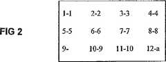
図1に示される本実施形態においては、マイクロアレイは、ブロックA、B、C、D、E以下同様と表示が付された64の同一のブロックを含む。円1及び2は、マイクロアレイ(図1)上の2つのウェルを表す(図1)。図2は、同一の検出ブロックのどの1つが同様に見えるかの例である。この単純化された例においては、ブロック内には、12の利用可能な特徴位置があり、ハイブリダイゼーション検定においてデータが求められる関心のある特徴の数は10であり、対照又は基準のために2つの特徴が残る。図2に示される各々の数の組における第1の数はブロックの特徴位置を定義し、第2の数は各々のプローブに指定される数を定義する。関心のある10のプローブは、プローブ1ないし10と表示が付され、それぞれ、特徴位置1から8、10、及び11に配置される。特徴位置9における特徴にはどのようなプローブも構成されておらず、したがって、これはブランク位置又は負の制御である。特徴位置12における特徴は、ハイブリダイゼーションに対しては関心のあるのもではないが、実験用試料の中にスパイクされたヌクレオチドにハイブリダイズされるプローブ、すなわち正の制御を含有する。図1におけるマイクロアレイのすべての繰り返される検出ブロックは、対応する位置1から12において、同じ構成の特徴を有する。 In the present embodiment shown in FIG. 1, the microarray includes 64 identical blocks labeled as blocks A, B, C, D, E and so on.
図1及び図3は、完全なブロックにおける情報が、隣接するブロックからの部分的な情報をとることにより、どのように再構成されるかを示す。図1においては、ウェル1は完全な検出ブロックAを含み、したがって、1つのブロックからのすべての情報を含む。ウェル1におけるハイブリダイゼーションからの情報は、コーナを求めることにより読み込まれ、該コーナの位置から検出ブロックA全体がウェル1にあることが理解され、次いで、単純にデータを検出ブロックから読み込む。 1 and 3 show how the information in a complete block is reconstructed by taking partial information from adjacent blocks. In FIG. 1, well 1 contains a complete detection block A and thus contains all the information from one block. Information from the hybridization in
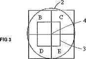
しかしながら、ウェル2は、如何なる単一の全体的な検出ブロックも含まない。しかしながら、ウェル2に囲まれたブロックBないしEの部分に含まれる情報を互いに統合することにより取得することができる全体的なブロックからの情報を含む。第1に、検出ブロックB、C、D、及びEの交差点におけるコーナが突き止められる。この単純な例においては、コーナは、暗い特徴(検出ブロックCの特徴9)に隣接する明るくされた特徴(ブロックBの特徴位置12)を探すことにより突き止めることができる。コーナの検出により、検出ブロックと同じ大きさのデータ抽出グリッド3をウェル2の内側に想定することができる(図3)。グリッドは、このように配置されるため、4つのブロックが互いに連結するコーナ点4がグリッド内に含まれる。次いで、グリッド内のすべての特徴からのデータを読み込んで、検出ブロック上で表わされるデータの組に組み立てることができる。 However, well 2 does not contain any single overall detection block. However, it includes information from the entire block that can be obtained by integrating the information contained in the portions of blocks B to E surrounded by the
データの組においては、暗い特徴の隣に明るくされた特徴の他の例がある傾向があるため、この単純な例におけるコーナを検出するのに用いられる方法は取るに足らないものであり、誤解を受けやすい。この例は、原理を示すものに過ぎない。実際の実施においては、データの組における特徴の数、及び対照又は基準の構成は、コーナの明白な検出を可能にするように、必要に応じて綿密にしてよい。さらに、幾つかの特徴は、ウェルにおいて何度も現れるため、他の特徴、さらにグリッド3の外側にある特徴の冗長な読み込み及び比較を用いてコーナを見出し、検出ブロックが正確に読み込まれていることを確実にすることができる。 The method used to detect corners in this simple example is trivial and misunderstood because in data sets there is a tendency to have other examples of brightened features next to dark features. It is easy to receive. This example is merely illustrative of the principle. In actual implementation, the number of features in the data set, and the configuration of the control or reference may be elaborated as needed to allow unambiguous detection of corners. In addition, some features appear many times in the well, so the corners are found using redundant readings and comparisons of other features and features outside the
上述の情報を互いに統合するマイクロアレイ及びその方法を考慮して、本発明のマイクロアレイを作り、これを用いて多数の試料を分析することは、十分に当業者の能力内にある。 Given the microarrays and methods that integrate the above information with each other, it is well within the ability of one skilled in the art to make a microarray of the invention and use it to analyze multiple samples.
明細書に述べられた本発明の例及び実施形態は、例示的なものであり、本発明を限定することを意図するものではない。本発明は、特許請求の範囲内にある例及び実施形態のすべての修正形態を包含する。 The examples and embodiments of the invention set forth in the specification are illustrative and are not intended to limit the invention. The present invention includes all modifications of the examples and embodiments within the scope of the claims.
Claims (11)
Translated fromJapanese検出ブロックを明確に識別するための少なくとも1つの信号であって、各特徴が前記少なくとも1つの信号に対して確認可能な位置を有する、前記信号、及び、
形状を有し、かつ検出ブロックよりも大きい、少なくとも第1の区画及び第2の区画を前記基板上に規定する物理的な障壁であって、各区画は、(1)各判別可能なプローブを含有する特徴の組の少なくとも1つであって、各区画中の特徴は少なくとも2つの判別可能なプローブを含有する特徴の組の員である、前記特徴と、(2)前記検出ブロックを明確に識別するための少なくとも1つの信号とを含み、前記少なくとも第1の区画と第2の区画とは互いに流体連通状態にない、前記物理的な障壁、を含むことを特徴とするマイクロアレイ。A microarray substrate comprising a plurality of identical detection blocks in a repeat unit adjacent to each other, each detection block comprising a set of features containing identically arranged distinguishable probes;
At least one signal for unambiguously identifying a detection block, wherein each feature has a position that is ascertainable with respect to the at least one signal; and
A physical barrier defining at least a first compartment and a second compartment on the substrate having a shape and larger than a detection block, wherein each compartment comprises: (1) each distinguishable probe;It is at least one of the set of features contained, characterized in each compartmentRu pairs membered derfeature that contains at least twodistinguishableprobe,and the feature,the(2) thedetection block clearand at least one signalfor identifying thesaidat least first not in fluid communication with each other and thecompartment and the second compartment, microarray which comprises the physical barrier.
互いに隣接する繰返し単位中の複数の同一の検出ブロックを含むマイクロアレイ基板を提供する工程であって、各々の検出ブロックは、同一に配置された判別可能なプローブを含有する特徴の組を含む、前記工程と、
検出ブロックを明確に識別するための少なくとも1つの信号を提供する工程であって、各特徴が前記少なくとも1つの信号に対して確認可能な位置を有する、前記工程と、
前記基板上に、形状を有し、かつ検出ブロックよりも大きい、少なくとも第1の区画及び第2の区画を規定する物理的な障壁を位置決めする工程であって、各区画は、各判別可能なプローブを含有する特徴の組の少なくとも1つであって、各区画中の特徴は少なくとも2つの判別可能なプローブを含有する特徴の組の員である、前記特徴と、前記検出ブロックを明確に識別するための少なくとも1つの信号とを含み、前記少なくとも第1の区画と第2の区画とは互いに流体連通状態にない、前記工程と、
を含むことを特徴とする方法。A method of making a microarray according to claim 1, comprising:
Providing a microarray substrate comprising a plurality of identical detection blocks in adjacent repeat units, each detection block comprising a set of features containing identically arranged distinguishable probes, Process,
Providing at least one signal for unambiguously identifying a detection block, wherein each feature has a position that is verifiable with respect to the at least one signal;
On the substrate has a shape, and larger than the detection block, comprising the steps of: positioning a physical barrier that defines at least a first compartment and a second compartment, each compartment iscapable respective discriminatedIt is at least one of the set of features containing probes, characterized in each compartmentRu pairs membered derfeature that contains at least twodistinguishable probesclearly and the feature,the detection block At least one signalfor identification, wherein theat least first and second compartments are not in fluid communication with each other;
A method comprising the steps of:
互いに隣接する繰返し単位中の複数の同一の検出ブロックを含むマイクロアレイ基板を提供する工程であって、各々の検出ブロックは、同一に配置された判別可能なプローブを含有する特徴の組を含む、前記工程と、
検出ブロックを明確に識別するための少なくとも1つの信号を提供する工程であって、各特徴が前記少なくとも1つの信号に対して確認可能な位置を有する、前記工程と、
前記基板上に、形状を有し、かつ検出ブロックよりも大きい、少なくとも第1の区画及び第2の区画を規定する物理的な障壁を位置決めする工程であって、各区画は、各判別可能なプローブを含有する特徴の組の少なくとも1つであって、各区画中の特徴は少なくとも2つの判別可能なプローブを含有する特徴の組の員である、前記特徴と、前記検出ブロックを明確に識別するための少なくとも1つの信号とを含み、前記少なくとも第1の区画と第2の区画とは互いに流体連通状態にない、前記工程と、
試料を前記区画に配置する工程と、
ハイブリダイゼーション実験を行う工程と、
前記ハイブリダイゼーション実験からデータを取得する工程と、
前記ハイブリダイゼーション実験からのデータから、特徴の完全な組を含む仮想検出ブロックを構成する工程と、
を含むことを特徴とする方法。A method for performing multiple hybridization experiments in parallel on a single microarray,
Providing a microarray substrate comprising a plurality of identical detection blocks in adjacent repeat units, each detection block comprising a set of features containing identically arranged distinguishable probes, Process,
Providing at least one signal for unambiguously identifying a detection block, wherein each feature has a position that is verifiable with respect to the at least one signal;
On the substrate has a shape, and larger than the detection block, comprising the steps of: positioning a physical barrier that defines at least a first compartment and a second compartment, each compartment iscapable respective discriminatedIt is at least one of the set of features containing probes, characterized in each compartmentRu pairs membered derfeature that contains at least twodistinguishable probesclearly and the feature,the detection block At least one signalfor identification, wherein theat least first and second compartments are not in fluid communication with each other;
Placing a sample in the compartment;
Performing a hybridization experiment;
Obtaining data from the hybridization experiment;
Constructing a virtual detection block containing a complete set of features from the data from the hybridization experiment;
A method comprising the steps of:
請求項1に記載のマイクロアレイを準備する工程と、
1つの試料を1つの区画内のプローブにハイブリダイズする工程と、
別の試料を別の区画内のプローブにハイブリダイズする工程と、
を含む方法。A method for performing a plurality of hybridization reactions on a plurality of samples on a single microarray,
Preparing the microarray of claim 1;
Hybridizing one sample to a probe in one compartment;
Hybridizing another sample to a probe in another compartment;
Including methods.
Applications Claiming Priority (2)
| Application Number | Priority Date | Filing Date | Title |
|---|---|---|---|
| US38355902P | 2002-05-24 | 2002-05-24 | |
| PCT/US2003/016429WO2003100012A2 (en) | 2002-05-24 | 2003-05-23 | Microarrays and method for running hybridization reaction for multiple samples on a single microarray |
Publications (2)
| Publication Number | Publication Date |
|---|---|
| JP2005527829A JP2005527829A (en) | 2005-09-15 |
| JP4544989B2true JP4544989B2 (en) | 2010-09-15 |
Family
ID=29584580
Family Applications (1)
| Application Number | Title | Priority Date | Filing Date |
|---|---|---|---|
| JP2004508254AExpired - Fee RelatedJP4544989B2 (en) | 2002-05-24 | 2003-05-23 | Microarray for performing hybridization reaction of multiple samples on single microarray and method therefor |
Country Status (8)
| Country | Link |
|---|---|
| US (1) | US7888106B2 (en) |
| EP (1) | EP1546378B1 (en) |
| JP (1) | JP4544989B2 (en) |
| AT (1) | ATE513923T1 (en) |
| AU (1) | AU2003241607B2 (en) |
| CA (1) | CA2487093A1 (en) |
| IS (1) | IS7611A (en) |
| WO (1) | WO2003100012A2 (en) |
Families Citing this family (76)
| Publication number | Priority date | Publication date | Assignee | Title |
|---|---|---|---|---|
| US7563600B2 (en)* | 2002-09-12 | 2009-07-21 | Combimatrix Corporation | Microarray synthesis and assembly of gene-length polynucleotides |
| CA2557841A1 (en) | 2004-02-27 | 2005-09-09 | President And Fellows Of Harvard College | Polony fluorescent in situ sequencing beads |
| EP2290068A3 (en) | 2004-05-28 | 2012-01-04 | Asuragen, Inc. | Methods and compositions involving microRNA |
| US20060073486A1 (en)* | 2004-10-01 | 2006-04-06 | Sana Theodore R | Multiple array substrates and methods for using the same |
| EP2284265B1 (en) | 2004-11-12 | 2015-01-07 | Asuragen, Inc. | Methods and compositions involving miRNA and miRNA inhibitor molecules |
| WO2008027558A2 (en) | 2006-08-31 | 2008-03-06 | Codon Devices, Inc. | Iterative nucleic acid assembly using activation of vector-encoded traits |
| EP2145001A2 (en) | 2006-09-19 | 2010-01-20 | Asuragen, Inc. | Mir-15, mir-26, mir -31,mir -145, mir-147, mir-188, mir-215, mir-216 mir-331, mmu-mir-292-3p regulated genes and pathways as targets for therapeutic intervention |
| EP2487240B1 (en) | 2006-09-19 | 2016-11-16 | Interpace Diagnostics, LLC | Micrornas differentially expressed in pancreatic diseases and uses thereof |
| WO2009036332A1 (en) | 2007-09-14 | 2009-03-19 | Asuragen, Inc. | Micrornas differentially expressed in cervical cancer and uses thereof |
| EP2990487A1 (en) | 2008-05-08 | 2016-03-02 | Asuragen, INC. | Compositions and methods related to mirna modulation of neovascularization or angiogenesis |
| WO2010025310A2 (en) | 2008-08-27 | 2010-03-04 | Westend Asset Clearinghouse Company, Llc | Methods and devices for high fidelity polynucleotide synthesis |
| US10207240B2 (en) | 2009-11-03 | 2019-02-19 | Gen9, Inc. | Methods and microfluidic devices for the manipulation of droplets in high fidelity polynucleotide assembly |
| ES2574055T3 (en) | 2009-11-25 | 2016-06-14 | Gen9, Inc. | Methods and apparatus for error reduction in chip-based DNA |
| WO2011066185A1 (en) | 2009-11-25 | 2011-06-03 | Gen9, Inc. | Microfluidic devices and methods for gene synthesis |
| WO2011085075A2 (en) | 2010-01-07 | 2011-07-14 | Gen9, Inc. | Assembly of high fidelity polynucleotides |
| US8716467B2 (en) | 2010-03-03 | 2014-05-06 | Gen9, Inc. | Methods and devices for nucleic acid synthesis |
| ES2631458T3 (en) | 2010-03-04 | 2017-08-31 | Interna Technologies B.V. | MRNA molecule defined by its source and its therapeutic uses in cancer associated with EMT |
| WO2011143556A1 (en) | 2010-05-13 | 2011-11-17 | Gen9, Inc. | Methods for nucleotide sequencing and high fidelity polynucleotide synthesis |
| US9187777B2 (en) | 2010-05-28 | 2015-11-17 | Gen9, Inc. | Methods and devices for in situ nucleic acid synthesis |
| NZ719520A (en) | 2010-07-06 | 2017-07-28 | Int Tech Bv | Mirna and its diagnostic and therapeutic uses in diseases or conditions associated with melanoma, or in diseases or conditions associated with activated braf pathway |
| EP4039363A1 (en) | 2010-11-12 | 2022-08-10 | Gen9, Inc. | Protein arrays and methods of using and making the same |
| EP3360963B1 (en) | 2010-11-12 | 2019-11-06 | Gen9, Inc. | Methods and devices for nucleic acids synthesis |
| EP2640851A2 (en) | 2010-11-17 | 2013-09-25 | Asuragen, Inc. | Mirnas as biomarkers for distinguishing benign from malignant thyroid neoplasms |
| EP2474617A1 (en) | 2011-01-11 | 2012-07-11 | InteRNA Technologies BV | Mir for treating neo-angiogenesis |
| CA2828532A1 (en) | 2011-02-28 | 2012-11-22 | University Of Iowa Research Foundation | Anti-mullerian hormone changes in pregnancy and prediction of adverse pregnancy outcomes and gender |
| CN107881166A (en) | 2011-06-15 | 2018-04-06 | Gen9股份有限公司 | The method of preparative body outer clone |
| US9752176B2 (en) | 2011-06-15 | 2017-09-05 | Ginkgo Bioworks, Inc. | Methods for preparative in vitro cloning |
| IL280334B2 (en) | 2011-08-26 | 2023-09-01 | Gen9 Inc | Compositions and methods for high fidelity assembly of nucleic acids |
| US9644241B2 (en) | 2011-09-13 | 2017-05-09 | Interpace Diagnostics, Llc | Methods and compositions involving miR-135B for distinguishing pancreatic cancer from benign pancreatic disease |
| JP2014531908A (en) | 2011-10-14 | 2014-12-04 | プレジデント アンド フェローズ オブ ハーバード カレッジ | Sequencing by structural assembly |
| WO2013063519A1 (en) | 2011-10-26 | 2013-05-02 | Asuragen, Inc. | Methods and compositions involving mirna expression levels for distinguishing pancreatic cysts |
| US20130142728A1 (en) | 2011-10-27 | 2013-06-06 | Asuragen, Inc. | Mirnas as diagnostic biomarkers to distinguish benign from malignant thyroid tumors |
| US9150853B2 (en) | 2012-03-21 | 2015-10-06 | Gen9, Inc. | Methods for screening proteins using DNA encoded chemical libraries as templates for enzyme catalysis |
| AU2013251701A1 (en) | 2012-04-24 | 2014-10-30 | Gen9, Inc. | Methods for sorting nucleic acids and multiplexed preparative in vitro cloning |
| US9914967B2 (en) | 2012-06-05 | 2018-03-13 | President And Fellows Of Harvard College | Spatial sequencing of nucleic acids using DNA origami probes |
| CA2877823A1 (en) | 2012-06-25 | 2014-01-03 | Gen9, Inc. | Methods for nucleic acid assembly and high throughput sequencing |
| US20150152499A1 (en) | 2012-07-03 | 2015-06-04 | Interna Technologies B.V. | Diagnostic portfolio and its uses |
| CN108875312A (en) | 2012-07-19 | 2018-11-23 | 哈佛大学校长及研究员协会 | Utilize the method for nucleic acid storage information |
| WO2014055117A1 (en) | 2012-10-04 | 2014-04-10 | Asuragen, Inc. | Diagnostic mirnas for differential diagnosis of incidental pancreatic cystic lesions |
| US9476089B2 (en) | 2012-10-18 | 2016-10-25 | President And Fellows Of Harvard College | Methods of making oligonucleotide probes |
| EP3578666A1 (en) | 2013-03-12 | 2019-12-11 | President and Fellows of Harvard College | Method of generating a three-dimensional nucleic acid containing matrix |
| WO2014145612A1 (en) | 2013-03-15 | 2014-09-18 | Ajay Goel | Tissue and blood-based mirna biomarkers for the diagnosis, prognosis and metastasis-predictive potential in colorectal cancer |
| EP2971149B1 (en) | 2013-03-15 | 2018-05-09 | Baylor Research Institute | Ulcerative colitis (uc)-associated colorectal neoplasia markers |
| ES2935257T3 (en) | 2013-03-15 | 2023-03-03 | Univ Chicago | Methods and Compositions Related to T Cell Activity |
| KR102423377B1 (en) | 2013-08-05 | 2022-07-25 | 트위스트 바이오사이언스 코포레이션 | De novo synthesized gene libraries |
| US10669304B2 (en) | 2015-02-04 | 2020-06-02 | Twist Bioscience Corporation | Methods and devices for de novo oligonucleic acid assembly |
| CA2975855A1 (en) | 2015-02-04 | 2016-08-11 | Twist Bioscience Corporation | Compositions and methods for synthetic gene assembly |
| CN107429216B (en) | 2015-02-10 | 2023-01-24 | 美国亚德诺半导体公司 | Device and method for detecting molecules and binding energy |
| US9981239B2 (en) | 2015-04-21 | 2018-05-29 | Twist Bioscience Corporation | Devices and methods for oligonucleic acid library synthesis |
| CA2998169A1 (en) | 2015-09-18 | 2017-03-23 | Twist Bioscience Corporation | Oligonucleic acid variant libraries and synthesis thereof |
| KR102794025B1 (en) | 2015-09-22 | 2025-04-09 | 트위스트 바이오사이언스 코포레이션 | Flexible substrates for nucleic acid synthesis |
| EP3384077A4 (en) | 2015-12-01 | 2019-05-08 | Twist Bioscience Corporation | FUNCTIONALIZED SURFACES AND THEIR PREPARATION |
| US10444179B2 (en) | 2016-08-10 | 2019-10-15 | Multerra Bio, Inc. | Apparatuses and methods for detecting molecules and binding energy |
| US9816988B1 (en) | 2016-08-10 | 2017-11-14 | Multerra Bio, Inc. | Apparatuses and methods for detecting molecules and binding energy |
| SG11201901563UA (en) | 2016-08-22 | 2019-03-28 | Twist Bioscience Corp | De novo synthesized nucleic acid libraries |
| US10417457B2 (en) | 2016-09-21 | 2019-09-17 | Twist Bioscience Corporation | Nucleic acid based data storage |
| EA201991262A1 (en) | 2016-12-16 | 2020-04-07 | Твист Байосайенс Корпорейшн | LIBRARIES OF OPTIONS OF IMMUNOLOGICAL SYNAPSIS AND THEIR SYNTHESIS |
| CN110892485B (en) | 2017-02-22 | 2024-03-22 | 特韦斯特生物科学公司 | Nucleic acid-based data storage |
| CA3056388A1 (en) | 2017-03-15 | 2018-09-20 | Twist Bioscience Corporation | Variant libraries of the immunological synapse and synthesis thereof |
| IL271205B2 (en) | 2017-06-12 | 2025-02-01 | Twist Bioscience Corp | Methods for seamless nucleic acid assembly |
| WO2018231864A1 (en) | 2017-06-12 | 2018-12-20 | Twist Bioscience Corporation | Methods for seamless nucleic acid assembly |
| US11407837B2 (en) | 2017-09-11 | 2022-08-09 | Twist Bioscience Corporation | GPCR binding proteins and synthesis thereof |
| KR102637566B1 (en) | 2017-10-20 | 2024-02-16 | 트위스트 바이오사이언스 코포레이션 | Heated nanowells for polynucleotide synthesis |
| WO2019086603A1 (en) | 2017-11-03 | 2019-05-09 | Interna Technologies B.V. | Mirna molecule, equivalent, antagomir, or source thereof for treating and/or diagnosing a condition and/or a disease associated with neuronal deficiency or for neuronal (re)generation |
| EP3714053A4 (en) | 2017-11-22 | 2021-11-24 | The University of Chicago | CHEMICAL PROBE DEPENDENT EVALUATION OF PROTEINACTIVITY AND USE OF IT |
| SG11202006460SA (en) | 2018-01-04 | 2020-08-28 | Twist Bioscience Corp | Dna-based digital information storage |
| EP3814497A4 (en) | 2018-05-18 | 2022-03-02 | Twist Bioscience Corporation | POLYNUCLEOTIDES, REAGENTS, AND METHODS FOR NUCLEIC ACID HYBRIDIZATION |
| CN119708086A (en) | 2018-12-26 | 2025-03-28 | 特韦斯特生物科学公司 | Highly accurate de novo polynucleotide synthesis |
| CN113785057A (en) | 2019-02-26 | 2021-12-10 | 特韦斯特生物科学公司 | Variant nucleic acid libraries for antibody optimization |
| US11492727B2 (en) | 2019-02-26 | 2022-11-08 | Twist Bioscience Corporation | Variant nucleic acid libraries for GLP1 receptor |
| WO2020206285A1 (en) | 2019-04-05 | 2020-10-08 | Board Of Regents, The University Of Texas System | Methods and applications for cell barcoding |
| WO2020210521A2 (en) | 2019-04-12 | 2020-10-15 | The Regents Of The University Of California | Compositions and methods for increasing muscle mass and oxidative metabolism |
| WO2020257612A1 (en) | 2019-06-21 | 2020-12-24 | Twist Bioscience Corporation | Barcode-based nucleic acid sequence assembly |
| WO2021061842A1 (en) | 2019-09-23 | 2021-04-01 | Twist Bioscience Corporation | Variant nucleic acid libraries for single domain antibodies |
| WO2021061829A1 (en) | 2019-09-23 | 2021-04-01 | Twist Bioscience Corporation | Variant nucleic acid libraries for crth2 |
| WO2024028794A1 (en) | 2022-08-02 | 2024-02-08 | Temple Therapeutics BV | Methods for treating endometrial and ovarian hyperproliferative disorders |
Family Cites Families (7)
| Publication number | Priority date | Publication date | Assignee | Title |
|---|---|---|---|---|
| US5545531A (en)* | 1995-06-07 | 1996-08-13 | Affymax Technologies N.V. | Methods for making a device for concurrently processing multiple biological chip assays |
| US6300063B1 (en)* | 1995-11-29 | 2001-10-09 | Affymetrix, Inc. | Polymorphism detection |
| CA2389358C (en)* | 1996-12-31 | 2008-07-15 | Genometrix Incorporated | Multiplexed molecular analysis apparatus and method |
| US6232066B1 (en)* | 1997-12-19 | 2001-05-15 | Neogen, Inc. | High throughput assay system |
| FR2784189B3 (en)* | 1998-10-05 | 2000-11-03 | Commissariat Energie Atomique | BIOCHIP AND DEVICE FOR READING A BIOCHIP COMPRISING A PLURALITY OF MOLECULAR RECOGNITION AREAS |
| JP2000346847A (en)* | 1999-03-30 | 2000-12-15 | Fuji Photo Film Co Ltd | Method and device for detecting organism-derived material |
| US6699665B1 (en)* | 2000-11-08 | 2004-03-02 | Surface Logix, Inc. | Multiple array system for integrating bioarrays |
- 2003
- 2003-05-23JPJP2004508254Apatent/JP4544989B2/ennot_activeExpired - Fee Related
- 2003-05-23CACA002487093Apatent/CA2487093A1/ennot_activeAbandoned
- 2003-05-23AUAU2003241607Apatent/AU2003241607B2/ennot_activeCeased
- 2003-05-23EPEP03731356Apatent/EP1546378B1/ennot_activeExpired - Lifetime
- 2003-05-23USUS10/444,307patent/US7888106B2/ennot_activeExpired - Fee Related
- 2003-05-23ATAT03731356Tpatent/ATE513923T1/ennot_activeIP Right Cessation
- 2003-05-23WOPCT/US2003/016429patent/WO2003100012A2/enactiveApplication Filing
- 2004
- 2004-12-22ISIS7611Apatent/IS7611A/enunknown
Also Published As
| Publication number | Publication date |
|---|---|
| JP2005527829A (en) | 2005-09-15 |
| US20040009520A1 (en) | 2004-01-15 |
| IS7611A (en) | 2004-12-22 |
| EP1546378A4 (en) | 2006-07-26 |
| EP1546378B1 (en) | 2011-06-22 |
| AU2003241607B2 (en) | 2007-09-06 |
| US7888106B2 (en) | 2011-02-15 |
| CA2487093A1 (en) | 2003-12-04 |
| ATE513923T1 (en) | 2011-07-15 |
| WO2003100012A3 (en) | 2004-09-16 |
| WO2003100012A2 (en) | 2003-12-04 |
| AU2003241607A1 (en) | 2003-12-12 |
| EP1546378A2 (en) | 2005-06-29 |
Similar Documents
| Publication | Publication Date | Title |
|---|---|---|
| JP4544989B2 (en) | Microarray for performing hybridization reaction of multiple samples on single microarray and method therefor | |
| Moffitt et al. | The emerging landscape of spatial profiling technologies | |
| Bressan et al. | The dawn of spatial omics | |
| US20220333192A1 (en) | Methods and devices for spatial assessment of rna quality | |
| EP2132332B1 (en) | Measurement of an insoluble analyte in a sample | |
| US20060287833A1 (en) | Method and system for sequencing nucleic acid molecules using sequencing by hybridization and comparison with decoration patterns | |
| WO2003046223A1 (en) | Microarrays with visible pattern detection | |
| Deng et al. | Microtechnologies for single-cell and spatial multi-omics | |
| US11989265B2 (en) | Intensity extraction from oligonucleotide clusters for base calling | |
| Chen et al. | Mapping gene expression in the spatial dimension | |
| US8283158B2 (en) | Method and apparatus for performing multiple simultaneous manipulations of biomolecules in a two dimensional array | |
| Katsuma et al. | Genome medicine promised by microarray technology | |
| WO2023159028A1 (en) | Systems and methods for spatial analysis of analytes using fiducial alignment | |
| US20030156136A1 (en) | Method and system for visualization of results of feature extraction from molecular array data | |
| US20040241670A1 (en) | Method and system for partitioning pixels in a scanned image of a microarray into a set of feature pixels and a set of background pixels | |
| Tian et al. | Moving genomics into tissues | |
| EP4590849A1 (en) | Spatially resolved cellular profiling | |
| US20050049797A1 (en) | Method and system for displacement-vector-based detection of zone misalignment in microarray data | |
| US20250264330A1 (en) | Method and Apparatus for Assigning a Specific Reagent to a Reaction Space | |
| EP4497831A1 (en) | Analysis array and method for analysing a biological sample | |
| US12367263B2 (en) | Intensity extraction for feature values in base calling | |
| US20040241669A1 (en) | Optimized feature-characteristic determination used for extracting feature data from microarray data | |
| US6544777B1 (en) | Non-cognate hybridization system (NCHS) | |
| US20050226535A1 (en) | Method and system for rectilinearizing an image of a microarray having a non-rectilinear feature arrangement | |
| WO2025059045A1 (en) | Systems and methods for determining linkage of sequence reads on a flow cell |
Legal Events
| Date | Code | Title | Description |
|---|---|---|---|
| A621 | Written request for application examination | Free format text:JAPANESE INTERMEDIATE CODE: A621 Effective date:20060414 | |
| A977 | Report on retrieval | Free format text:JAPANESE INTERMEDIATE CODE: A971007 Effective date:20090130 | |
| A131 | Notification of reasons for refusal | Free format text:JAPANESE INTERMEDIATE CODE: A131 Effective date:20090302 | |
| A521 | Request for written amendment filed | Free format text:JAPANESE INTERMEDIATE CODE: A523 Effective date:20090601 | |
| A131 | Notification of reasons for refusal | Free format text:JAPANESE INTERMEDIATE CODE: A131 Effective date:20090721 | |
| A521 | Request for written amendment filed | Free format text:JAPANESE INTERMEDIATE CODE: A523 Effective date:20091021 | |
| TRDD | Decision of grant or rejection written | ||
| A01 | Written decision to grant a patent or to grant a registration (utility model) | Free format text:JAPANESE INTERMEDIATE CODE: A01 Effective date:20100531 | |
| A01 | Written decision to grant a patent or to grant a registration (utility model) | Free format text:JAPANESE INTERMEDIATE CODE: A01 | |
| A61 | First payment of annual fees (during grant procedure) | Free format text:JAPANESE INTERMEDIATE CODE: A61 Effective date:20100629 | |
| FPAY | Renewal fee payment (event date is renewal date of database) | Free format text:PAYMENT UNTIL: 20130709 Year of fee payment:3 | |
| R150 | Certificate of patent or registration of utility model | Free format text:JAPANESE INTERMEDIATE CODE: R150 | |
| R250 | Receipt of annual fees | Free format text:JAPANESE INTERMEDIATE CODE: R250 | |
| LAPS | Cancellation because of no payment of annual fees |